


INSTALLATION INSTRUCTIONS
SINGLE P ACKAGE
AIR CONDITIONERS
MODELS
P1124A2 P1224A1
P1130A2 P1230A1
P1136A2 P1236A1
P1142A3 P1242A1
P1148A2 P1248A2
P1060A1
Bard Manufacturing Company
Bryan, Ohio 43506
Since 1914 . . . Moving ahead just as planned
Manual : 2100-353C
Supersedes: 2100-353B
File: Volume II Tab 10
Date: 01-09-03
© Copyright 2003

CONTENTS
Getting Other Informations and Publications
General Instructions
Important ................................................................ 2
Shipping Damage .................................................... 2
General ................................................................ 2
Field Installed Heater Packages (Optional) ............. 2
Installation
Location ................................................................ 9
Typical Installations ................................................. 9
Condensate Drain Trap ......................................... 14
Air Filters .............................................................. 14
Wiring – Main Power ............................................. 15
Wiring – 24V Low Voltage Control Circuit ............. 15
Transformer Taps................................................... 15
Thermostats........................................................... 15
Figures
Figure 1 Unit Dimensions...................................... 8
Figure 2 Slab Mounting at Ground Level ............ 10
Figure 3 Airflow and Service Access
Clearances............................................ 10
Figure 4 Roof Top Application ..............................11
Figure 5 Elevated Mounting Platforms .................11
Figure 6 Prefabricated Rood Curb
Specifications........................................ 12
Figure 7 Field Fabricated Curbing....................... 13
Figure 8 Condensate Drain Trap......................... 14
Figure 9 Low Voltage Wiring ............................... 16
Figure 10 Fan Blade Setting ................................. 19
Figure 11 Brazing Diagram ................................... 20
Start Up and Operation
Three Phase Scroll Compressor Start Up
Information............................................................. 17
Sequence of Operation.......................................... 17
Start Up Notes ....................................................... 17
Indoor Blower Motor .............................................. 17
Compressor Control Module.................................. 17
Adjustments........................................................... 18
Service and Troubleshooting
Service Hints ......................................................... 19
Pressure Service Ports .......................................... 19
Refrigerant Charge ................................................ 19
Fan Blade Settings ................................................ 19
Suction and Discharge Tube Brazing .................... 20
Pressure Table....................................................... 14
Wiring Diagrams ............................................... 15-16
Troubleshooting ECM Blower Motors ............. 23-24
Tables
Table 1 Rated CFM & ESP .................................. 2
Table 2 Electrical Specifications .......................... 3
Table 2A Electrical Specifications .......................... 4
Table 2B Electrical Spedifications .......................... 5
Table 3 Option Field Installed Heater Packages . 6
Table 4 Electric Heater Table............................... 8
Table 5 Unit Dimensions...................................... 5
Table 6 Roof Curb Details ................................. 13
Table 7 Dimension for Figure 7.......................... 13
Table 8 Filter Requirements & Sizes ................. 14
Table 9 Thermostat Wire Size ........................... 15
Table 10 Wall Thermostat and Subbase
Combinations ........................................ 15
Table 11 Suction Line Temperatures ................... 19
Table 12 Fan Blade Setting Dimensions.............. 19
Table 13 Indoor Blower Performance .................. 20
Table 14 Pressure Table ...................................... 21
Table 14APressure Table ...................................... 22

Getting Other Information and Publications
These publications can help you install the air
conditioner or heat pump. You can usually find these at
your local library or purchase them directly from the
publisher. Be sure to consult current edition of each
standard.
National Electrical Code ...................... ANSI/NFPA 70
Standard for the Installation .............. ANSI/NFPA 90A
of Air Conditioning and
Ventilating Systems
Standard for Warm Air...................... ANSI/NFPA 90B
Heating and Air
Conditioning Systems
Load Calculation for............................ACCA Manual J
Residential Winter and
Summer Air Conditioning
FOR MORE INFORMATION, CONTACT
THESE PUBLISHERS:
ACCA Air Conditioning Contractors of America
1712 New Hampshire Ave. N.W.
Washington, DC 20009
Telephone: (202) 483-9370
Fax: (202) 234-4721
ANSI American National Standards Institute
11 West Street, 13th Floor
New York, NY 10036
Telephone: (212) 642-4900
Fax: (212) 302-1286
ASHRAE American Society of Heating, Refrigerating,
and Air Conditioning Engineers, Inc.
1791 Tullie Circle, N.E.
Atlanta, GA 30329-2305
Telephone: (404) 636-8400
Fax: (404) 321-5478
Duct Design for Residential .............. ACCA Manual D
Winter and Summer Air
Conditioning and Equipment Selection
NFPA National Fire Protection Association
Batterymarch Park
P.O. Box 9101
Quincy, MA 02269-9901
Telephone: (800) 344-3555
Fax: (617) 984-7057
Manual 2100-353
Page 1
GENERAL INSTRUCTIONS
IMPORTANT
The equipment covered in this manual is to be installed
by trained, experienced service and installation
technicians. All duct work, supply and return ducts,
must be properly sized for the design air flow
requirement of the equipment. ACCA is an excellent
guide to proper sizing. All duct work or portions
thereof not in the conditioned space should be properly
insulated in order to both conserve energy and prevent
condensation or moisture damage.
SHIPPING DAMAGE
Upon receipt of equipment, the carton should be
checked for external signs of shipping damage. If
damage is found, the receiving party must contact the
last carrier immediately, preferably in writing,
requesting inspection by the carrier’s agent.
GENERAL
The refrigerant system is completely assembled and
charged. All internal wiring is complete.
The unit is designed for use with or without duct work.
Flanges are provided for attaching the supply and return
ducts.
These instructions explain the recommended method to
install the air cooled self-contained unit and the
electrical wiring connections to the unit.
These instructions and any instructions packaged with
any separate equipment required to make up the entire
heat pump system should be carefully read before
beginning the installation. Note particularly “Starting
Procedure” and any tags and/or labels attached to the
equipment.
While these instructions are intended as a general
recommended guide, they do not supersede any national
and/or local codes in any way. Authorities having
jurisdiction should be consulted before the installation
is made.
FIELD INSTALLED HEATER PACKAGES
(OPTIONAL)
These packaged air conditions are manufactured
without supplementary electric heaters. Supplementary
heaters are available for simple, fast field installation.
A separate power circuit is required for the
supplementary heaters.
IMPORTANT: Refer to Table 1 when designing duct
work for maximum available static pressure with heater
installed.
Refer to data shown in Table 3 and 4 for proper
application information on all available heater
combinations and what units they can be used with. It
also shows the applicable circuit ampacities, fuse size,
and wire size for each heater combination.
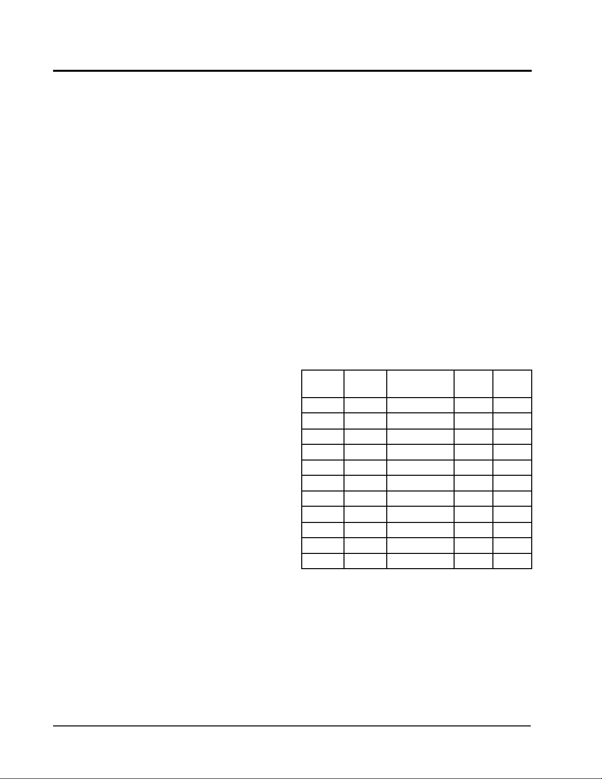
TABLE 1
RATED CFM AND EXTERNAL STATIC PRESSURE
(ESP)
ledoM
.oN
2A4211P008088-02702.005.0
1A4221P008
2A0311P52115721-020102.005.0
1A0321P0001
2A6311P05210041-051103.005.0
1A6321P0011
3A2411P00410451-062102.004.0
1A2421P0041
2A8411P05510071-004104.005.0
2A8421P0551
1A0601P00710781-035102.005.0
detaR
MFC
dednemmoceR
egnaRwolfriA
1etoN
1etoN
1etoN
1etoN
1etoN
detaR
PSE
01.005.0
51.005.0
51.005.0
02.005.0
02.005.0
PSE
.xaM
Manual 2100-353
Page 2
NOTE: ECM motors provide rated CFM up to 0.50 ESP

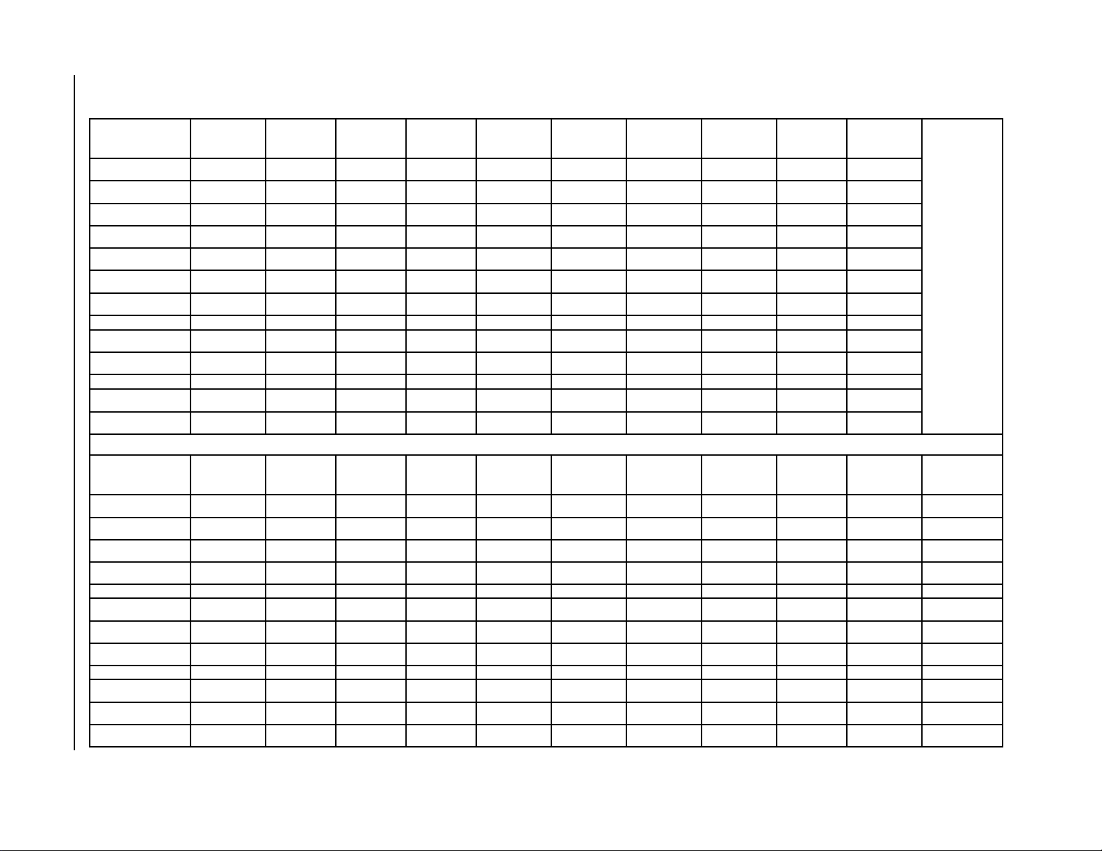
TABLE 2
ELECTRICAL SPECIFICATIONS
ledoM2A4211P2A0311P2A6311PB-1A6311PC-1A6311P3A2411P
–gnitaRcirtcelE
AtiucriC–zH06
1-06-802/0321-06-802/0321-06-802/0323-06-802/0323-06-0641-06-802/032
egnaRegatloVgnitarepO352-791352-791352-791352-781605-414352-791
yticapmAtiucriCmuminiM711252812192
CSCB3.016.3161116 5.81
*eziSeriWdleiF2101801418
eziSeriWdnuorG210101014101
**.xaM–esuFyaleD520304525154
802/032–spmAtinuatoT3.21/7.119.61/4.517.81/1.719.21/3.213.72.42/1.32
AtiucriC–rosserpmoC
epyTrosserpmoCllorcSllorcSllorcSllorcSllorcSllorcS
stloV802/032802/032802/032802/032064802/032
spmAdaoLdetaR0.9/4.86.31/1.214.51/8.316.9/0.99.45.81/0.71
spmAretoRkcoL65/655.27/5.2788/8877/7793401/401
resnednoCdnarotoMnaF
MPR/PH–rotoMnaF0901-5/15701-5/15701-5/15701-5/15701-5/15701-2/1
spmArotoMnaF2.16.16.16.10.15.2
MFC/.aiD–naF2491/"020042/"020012/"020002/"020002/"020582/"42
rotaropavEdnarotoM
MPR/PH–rotoMrewolB5701-3/15701-5/15701-5/15701-5/15701-5/15701-2/1
spmA–rotoMrewolB1.26.26.26.24.12.3
PSE&gnilooCMFC008
02.05211
@
02.00521
@
03.05721
@
03.05721
@
03.00041
@
).zo22R(egrahC454639393998
)sdnuop(thgieWgnippihS003013033033033093
@
02.0
Manual 2100-353
Page 3

TABLE 2A
ELECTRICAL SPECIFICATIONS
ledoM2A8411PB-2A8411PC-2A8411P1A0601PB-1A0601PC-1A0601P
–gnitaRcirtcelE
AtiucriC–zH06
1-06-802/0323-06-802/0323-06-0641-06-802/0323-06-0643-06-064
egnaRegatloVgnitarepO352-791352-781605-414352-791352-781605-414
yticapmAtiucriCmuminiM234221248241
CSCB5.027.41792219
*eziSeriWdleiF801218821
eziSeriWdnuorG010121010121
**.xaM–esuFyaleD055351065402
802/032–spmAtinuatoT2.62/2.421.91/9.718.87.33/9.037.32/7.122.11
AtiucriC–rosserpmoC
epyTrosserpmoCllorcSllorcSllorcSllorcSllorcSllorcS
stloV802/032802/032064802/032802/032064
spmAdaoLdetaR5.02/5.814.31/2.2162.82/2.5281/614.8
spmAretoRkcoL731/73119/1905961/961321/32126
resnednoCdnarotoMnaF
MPR/PH–rotoMnaF058-3/1058-3/1058-3/1058-3/1058-3/1058-3/1
spmArotoMnaF5.25.22.15.25.22.1
MFC/.aiD–naF0013/"420013/"420013/"420013/"420013/"420013/"42
rotaropavEdnarotoM
MPR/PH–rotoMrewolB5701-2/15701-2/15701-2/15701-2/15701-2/15701-2/1
spmA–rotoMrewolB2.32.36.12.32.36.1
PSE&gnilooCMFC0551
04.00551
@
04.00551
@
04.00071
@
02.00071
@
02.00071
@
02.0
@
).zo22R(egrahC 021021021
)sdnuop(thgieWgnippihS034034034524524524
Manual 2100-353
Page 4

TABLE 2B
ELECTRICAL SPECIFICATIONS
ledoM1A4221P1A0321P1A6321PB-1A6321P1A2421P2A8421PB-2A8421P
–gnitaRcirtcelE
AtiucriC–zH06
egnaRegatloVgnitarepO352-791352-791352-791352-781352-791352-791352-781
yticapmAtiucriCmuminiM
CSCB
*eziSeriWdleiF
eziSeriWdnuorG
**.xaM–esuFyaleD
802/032–spmAtinuatoT
AtiucriC–rosserpmoC
epyTrosserpmoCllorcSllorcSllorcSllorcSllorcSllorcSllorcS
stloV802/032802/032802/032802/032802/032802/032802/032
spmAdaoLdetaR
spmAretoRkcoL
resnednoCdnarotoMnaF
MPR/PH–rotoMnaF-5/19010 5701-5/15701-5/15701-5/1528-3/1528-3/1528-3/1
spmArotoMnaF2.16.16.16.15.25.25.2
MFC/.aiD–naF5791/"020042/"020012/"020012/"020092/"420532/"420532/"42
rotaropavEdnarotoM
MPR/PH–rotoMrewolBelbairaV3/1elbairaV2/1elbairaV2/1elbairaV2/1elbairaV2/1elbairaV2/1elbairaV2/1
spmA–rotoMrewolB2.27.23.33.33.45.45.4
PSE&gnilooCMFC008@ 01.00001@51.00011@51.051.0@00110041@02.00551@02.002.0@0551
).zo22R(egrahC3588201201811
)sdnuop(thgieWgnippihS003033043043014034034
1-06-802/0321-06-802/0321-06-802/0323-06-802/0321-06-802/0321-06-802/0323-06-802/032
71
3.01
21
21
52
4.21/8.11
0.9/4.8
65/65
12529103
5.312.619.0181
018 018
01010101
03045254
1.71/7.511.12/2.918.51/9.411.42/2.32
8.21/4.112.61/3.419.01/013.71/4.61
67/675.09/5.0977/77401/401
4332
128.21
68
0101
0553
72/5.527.91/4.91
02/5.817.21/4.21
731/73119/19
151151
Manual 2100-353
Page 5
Manual 2100-353
Page 6
TABLE 3
OPTIONAL FIELD INSTALLED HEATER PACKAGES
ONLY TO BE USED WITH THE MODELS INDICATED
egakcaPretaeH
ledoM
&stloV
esahP2A4211P1A4211P2A0311P1A0321P2A6321PC-1A6311PC-1A6311P1A6321PB-1A6321P
50A-BP3HE1-802/042SANS AN SAAANAN
80A-BP3HE1-802/042SANS AN SAAANAN
01A-BP3HE1-802/042SANSSSAAS AN
51A-BP3HE1-802/042ANANS AN SAAANAN
50A-CP3HE1-802/042ANSANS ANANANSAN
01A-CP3HE1-802/042ANSANANANANANANAN
nmulocsihT
knalbtfelsi
.yllanoitnetni
51A-CP3HE1-802/042ANANANS ANANANSAN
90B-BP3HE3-802/042AANA AN ASAANS
51B-BP3HE3-802/042ANANA AN ASA ANS
90C-BPHE3-084ANANA AN AASANAN
51C-BPHE3-084ANANA AN AASANAN
egakcaPretaeH
ledoM
&stloV
esahP3A2411P1A2421P2A8411PB-2A8411PC-2A8411P2A8421PB-2A8421P1A0601PB-1A0601PC-1A0601P
50A-BP5HE1-802/042 SSS A A S A S A A
01A-BP5HE1-802/042 SSS A A S A S A A
51A-BP5HE1-802/042 SSS A A S A S A A
02A-BP5HE1-802/042SANSA A ANANSA A
90B-BP5HE3-802/042 AAA S A A S A S A
51B-BP5HE3-802/042 AAA S A A S A S A
81B-BP5HE3-802/042AANASA ANANAS A
90C-CP5HE3-084AANAAS ANANAA S
51C-CP5HE3-084AANAAS ANANAA S
81C-CP5HE3-084AANAAS ANANAA S
S = Standard Application – Heater volts and phase same as basic unit A = Alternate Application – Heater volts and phase different from basic unit.
N = Not Approved
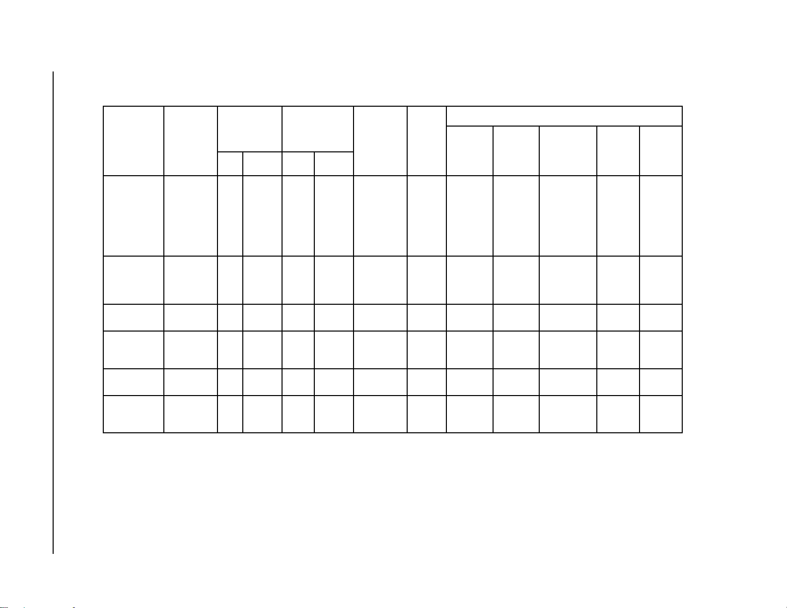
TABLE 4
OPTIONAL FIELD INSTALLED ELECTRIC HEATER TABLE
1
BtiucriC
2
revO.xaM
tnerruC
noitcetorP
52/03
04/54
05/06
07/08
52/03
05/06
07/08
52/03
05/06
07/08
001/011
52/03
04/05
52/03
04/05
05/06
51
52
51
52
03
dleiF
gniriW
01/01
01/01
8/6
4/4
01/01
8/6
4/4
01/01
8/6
4/4
3/2
01/01
8/8
01/01
8/8
8/6
41
01
41
01
01
3
dnuorG
rewoP
eriW
eziSWKHUTBWKHUTB
01
01
01
8
01
01
8
01
01
8
6
01
01
01
01
01
41
01
41
01
01
&WK.rtH
yticapaC
stloV042@
.gkPretaeH
.oNledoM
50A-BP3HE
80A-BP3HE
01A-BP3HE
51A-BP3HE
80A-CP3HE
01A-CP3HE
51A-CP3HE
50A-BP5HE
01A-BP5HE
51A-BP5HE
02A-BP5HE
90B-BP3HE
51B-BP3HE
90B-BP5HE
51B-BP5HE
81B-BP5HE
90C-BP3HE
51C-BP3HE
90C-BP5HE
51C-BP5HE
81C-BP5HE
stloVtinU
sesahP
1-802/042
5
1-802/042
8
1-802/042
01
1-802/042
51
1-802/042
5
1-802/042
01
1-802/042
51
1-802/042
5
1-802/042
01
1-802/042
51
1-802/042
02
3-802/042
9
3-802/042
51
3-802/042
9
3-802/042
51
3-802/042
81
3-084
3-084
3-084
3-084
3-084
9
51
9
51
81
001,71
003,72
001,43
002,15
001,71
001,43
002,15
001,71
001,43
002,15
002,86
007,03
002,15
007,03
002,15
004,16
007,03
002,15
007,03
002,15
004,16
&WK.rtH
yticapaC
stloV802@
V802/042
spmA.rtH
57.3
00.6
05.7
52.11
57.3
05.7
52.11
57.3
05.7
52.11
00.51
57.6
52.11
57.6
52.11
05.31
62.8
77.31
62.8
77.31
35.61
008,21
005,02
000,62
004,83
008,21
000,62
004,83
008,21
000,62
004,83
002,15
000,32
004,83
000,32
004,83
001,64
002,82
000,74
002,82
000,74
004,65
1.81/8.02
8.82/3.33
2.63/6.14
1.45/5.26
1.81/8.02
2.63/6.14
1.45/5.26
1.81/8.02
2.63/6.14
1.45/5.26
1.27/2.38
7.81/7.12
2.13/2.63
7.81/7.12
2.13/2.63
5.73/4.34
8.01
0.81
8.01
0.81
7.12
retaeH
lanretnI
sesuF
06/03
06/03
06/03
06/06
dleiF.oN
stiucriC
1
1
1
1
1
1
1
1
1
1
1
1
1
1
1
1
1
1
1
1
1
.niM
tiucriC
yticapmA
32/62
63/24
64/35
86/97
32/62
64/35
86/97
32/62
64/35
86/97
19/401
42/82
93/64
42/82
93/64
74/55
51
32
51
32
82
Manual 2100-353
Page 7
Time Delay fuses of “HACR” type circuit breakers must be used for 60 and smaller sizes. Standard fuses or circuit breakers are suitable for sizes
j
70 and larger. 480V circuit breakers are not “HACR” type.
Based on wire suitable for 75 degree C. Other wiring materials must be rated for marked “Minimum Circuit Ampacity” or greater.
k
Based upon Table 250-95 of N.E.C. 1993. See electric data for basic heat pump for Circuit A wiring specification requirements.
l
IMPORTANT: While this electrical data is presented as a guide, it is important to electrically connect properly sized fuses
and conductor wires in accordance with the National Electrical Code and all existing local codes.

FIGURE 1
DIMENSIONS OF UNITS
MIS-1305
TABLE 5
DIMENSIONS OF UNITS
)sehcnI(gninepOtcuD
ledoM
.oN
ABCJKLMDEFG
)sehcnI(snoisnemiDtenibaClanimoN
egrahcsiDriAnruteR
H
2A4211P
1A4221P
2A0311P
1A0321P
4/1-4261/3-848/1-838/1-628/1-261/961/933633418/7
2A6311P
1A6321P
3A2411P
1A2421P
2A8411P
4/1-130524623 4/3-261/9-7830183618/3-1
2A8421P
1A0601P
Manual 2100-353
Page 8

INSTALLATION
LOCATION
GENERAL
The unit must be located outside, or in a well ventilated
area. It must not be in the space being heated or cooled.
A sound absorbing material should be considered if the
unit is to be installed in such a position or location that
might cause transmission of sound or vibration to the
living area or adjacent buildings.
SLAB MOUNTING
In areas where winter temperatures DO NOT go below
32° F for periods over twelve hours, the unit may be
slab mounted at grade level. When installing unit at
grade level, install on a concrete slab at least four
inches above finished grade level. Slab should have a
slope tolerance away from the building structure of at
lease 1/4 inch per foot, while being level from side to
side. Place slab in a location where runoff water from
higher ground will not collect around unit. See
Figure 2.
A minimum of 18 inches should be provided between
the coil inlet and any building surfaces. Provide at least
four feet between coil outlet and any building wall,
fences or other vertical structures. Provide a minimum
of three feet clearance on the service access side of the
unit. See Figure 3.
ROOF MOUNTING
When a unit is installed in areas where low ambient
temperatures or strong winter winds exist, it should be
placed for prevailing winter winds are not in direct line
with the outdoor coil. If this is not possible, a wind
barrier should be constructed. Place barrier 24 inches
from the coil inlet side of the unit and in the direction
of prevailing winds. Size barrier at least the same
height and width as the unit. This may be necessary on
ground level installations, also. See Figure 4.
WINTER INSTALLA TION BELOW 32°F
In areas where winter conditions go below 32°F for
extended periods, the unit must be elevated above the
mounting surface to prevent snowfall or ice
accumulation from interfering with the operation of the
unit. A minimum of twelve inch elevation is
recommended, while greater elevation may be required
for areas of high snow accumulation. Poured concrete,
steel framework, brick, cement block, etc., can be
utilized to construct a suitable raised mounting
platform. See Figure 5.
TYPICAL INSTALLATIONS
1.
ROOF MOUNTED
sturdy base on the roof of the building. Return air
to the unit is brought through a single return grille
(grilles with built-in filters are best since they
enable easy access for filter changing). Return air
ducts are attached to the lower section of the front
panel. Supply air is brought from the unit to attic
duct work or to a furred down hall. Supply air duct
is attached to the top of the front panel.
CAUTION: All outdoor duct work must be
thoroughly insulated and weatherproofed. All
attic duct work must be thoroughly insulated.
Two inch thick insulation with suitable vapor
barrier is recommended for both outdoor and
attic runs.
In roof top installation, as in all installations, the air
conditioner must be level from side to side.
However, the unit should have a pitch along the
length to assure complete external drainage of
precipitation and of defrost condensate. See Figures
6 and 7, and Tables 6 and 7.
2.
CRAWL SPACE
space must be well insulated and provided with a
vapor barrier. In addition, the crawl space must be
thoroughly ventilated and provided with a good
vapor barrier as a ground cover. It is most desirable
to install the unit will be outdoors rather than inside
the crawl space, so that it will be readily accessible
for service.
3.
SLAB MOUNTED AT GROUND LEVEL
type installation is ideal for homes with a slab floor
construction where a roof mounted unit is not
desired. The supply and return duct work can be run
through a furred closet space.
4.
THROUGH THE WALL
requires a suitable framework to be fabricated
capable of withstanding the unit weight. Normally
the unit will be insulated so as to minimize supply
and return duct work.
– The unit is mounted on a
– Duct work installed in crawl
– This type installation
– This
Manual 2100-353
Page 9

FIGURE 2
SLAB MOUNTING AT GROUND LEVEL
(Above 32°F Outside Temperature)
FIGURE 3
AIRFLOW AND SERVICE ACCESS CLEARANCES
MIS-1184
Manual 2100-353
Page 10
MIS-1185

FIGURE 4
ROOF TOP APPLICATION
(May also be required for ground level installations)
MIS-1176
FIGURE 5
ELEVATED MOUNTING PLATFORMS
MIS-1183
Manual 2100-353
Page 11

Manual 2100-353
Page 12
FIGURE 6
PREFABRICATED ROOF CURB SPECIFICATIONS
HEAVY GAUGE GALVANIZED WITH WOOD NAILING STRIP, WELDED/LEAKPROOF
ONCE PIECE CONSTRUCTION – READY TO INSTALL
MIS-1177C

TABLE 6
ROOF CURB DETAILS
(Refer to Figure 7)
fooR
dooH
ledoMtinU
3A4211P
2A4221P
2A0311P
1A0321P
2A6311P
1A6321P
3A2411P
1A2421P
2A8411P
2A8421P
1A0601P
ledoM
63-EHR300-2409573.0852.0452.73573.83573.532452.42521.91881.8457.41521.8352.83
06-EHR400-2409573.28521.44521.14573.83573.534452.13521.910557.412452.83
fooR
bruC
ABCDEFGH IJKL
ledoM
sliateDbruCfooR
FIGURE 7
FIELD FABRICATED CURBING
MIS-1178A
j
A SEPARATE METAL FLASHING SHOULD BE
INSTALLED AROUND WOOD CURBING. CAULK
AND SEAL ALL JOINTS AND WEATHERPROOF.
TABLE 7
DIMENSION FOR X IN FIG. 7
ledoMtinU
dooHfooR
ledoM
noisnemiD
X
2A4211P
1A4221P
2A0311P
1A0321P
63-EHR14
2A6311P
1A6321P
3A2411P
1A2421P
2A8411P
06EHR8/7-44
2A8421P
1A0601P
Manual 2100-353
Page 13

5.
OTHER INSTALLATIONS
– Many other
installations are possible with the packaged air
conditioner. No matter what the installation, always
consider the following facts:
A. Insure that the discharge air is not obstructed in
any way so as to cause operation difficulties.
B. The indoor coil drain pan is equipped with a
coupling that must be piped through a
condensate drain trap to a suitable drain.
C. Always mount the unit is such a position that it
may be easily reached for servicing and
maintenance.
D. Insure that the unit is clear so that proper air
flow over the outdoor coil will be maintained.
If this unit is operated in cooling below a 65° outdoor
ambient temperature, the installation of low ambient
controls (CMA-6) to unit is required.
CONDENSATE DRAIN TRAP
It is very important to provide a trap in the condensate
drain line to allow a positive liquid seal in the line and
assure correct drainage from the coil condensate pan.
Install condensate drain trap shown in Figure 8. Use
drain connection size or larger. Do not operate unit
without trap. Unit must be level or slightly inclined
toward drain. With a trap installed on a unit located in
an unconditioned area, water in the trap may freeze. It
is recommended that the trap material be of a type that
will allow for expansion of water when it freezes.
AIR FILTERS
Air filters for the return air side of the system are not
provided as part of these models, and must be field
supplied and installed as part of the final installation.
Prior thought should be given to return air location and
placement of the air filter(s). The air filter(s) must be
of adequate size and readily accessible to the operator
of the equipment. Filters must be adequate in size and
properly maintained for proper operation. If this is not
done, excessive energy use, poor performance, and
multiple service problems will result. It is impossible to
oversize air filters. Generous sizing will result in
cleaner air and coils as well as lower operating costs
and extend the time between required changes. Table 8
shows minimum filter areas and recommended filter
sizes. Actual filter sizes can vary with the installation
due to single or multiple returns utilizing a filter/grille
arrangement or being placed immediately ahead of the
indoor coil face in the return air duct.
TABLE 8
FILTER REQUIREMENTS & SIZES
.oNledoMaerAretliFmuminiM
2A4211P
1A4221P
2A0311P
1A0321P
2A6311P
1A6321P
3A2411P
1A2421P
2A8411P
2A8421P
1A0601P
sehcnIerauqS264
)teeFerauqS12.3(
sehcnIerauqS806
)teeFerauqS26.4(
eziS
1x8/5-03x51
1x02x61)2(
NOTE: If roof hood accessory is to be used,
information on air filters may be found under
that heading in this manual. Air filters are
supplied as part of that package.
dednemmoceR
Manual 2100-353
Page 14
FIGURE 8
CONDENSATE DRAIN TRAP
MIS-136

AVremrofsnarTALFeguaGeriW
mumixaM
ecnatsiD
teeFnI
553.2
02
81
61
41
21
54
06
001
061
052
WIRING – MAIN POWER
Refer to the unit rating plate for wire sizing information
and maximum fuse size. Each outdoor unit is marked
with a “Minimum Circuit Ampacity”. This means that
the field wiring used must be sized to carry that amount
of current. If field installed heaters are added to the
basic unit, a second separate power supply circuit will
be required. The heater rating plate located adjacent to
the basic unit rating plate will show the appropriate
circuit ampacity fuse size, etc. (Also see “Electrical
Specifications” on pages 3, 4 and 5.) All models are
suitable for connection with copper wire only. These
instructions must be adhered to. Refer to the National
Electrical Code for complete current carrying capacity
data on the various insulation grades of wiring material.
The electrical specifications list fuse and wire sizes
(75°F copper) for all models including the most
commonly used heater sizes.
The unit rating plate lists a “Maximum Time Delay
Fuse” or “HACR” type circuit breaker that is to be used
with the equipment. The correct size must be used for
proper circuit protection and also to assure that there
will be no nuisance tripping due to the momentary high
starting current of the compressor.
WIRING – 24V LOW VOLTAGE CONTROL
CIRCUIT
Five (5) wires should be run from thermostat subbase to
the 24V terminal board in the unit. A five conductor,
18 gauge copper, color-coded thermostat cable is
recommended. The connection points are shown in
Figure 9.
TABLE 9
THERMOSTAT WIRE SIZE
TRANSFORMER TAPS
230/208V, 1 phase and 3 phase equipment employ dual
primary voltage transformers. All equipment leaves the
factory wired on 240V tap. For 208V operation,
reconnect from 240V to 208V tap. The acceptable
operating voltage range for the 240 and 208V taps are:
TAP RANGE
240 253 – 216
208 220 – 187
NOTE: The voltage should be measured at the field
power connection point in the unit and while
the unit is operating at full load (maximum
amperage operating condition).
THERMOSTATS
See specific wiring information for the different models, heater KWs, and voltages on unit and heating wiring
diagrams..
IMPORTANT NOTE: Only the thermostat and subbase combinations as shown above will work with this
TABLE 10
WALL THERMOSTAT AND SUBBASE COMBINATIONS
tatsomrehTesabbuSserutaeFtnanimoderP
220-3048
1113F78T
140-3048
9941C4308T
940-3048
083-39F1
340-3048
002MC
840-3048
3131C0048T
910-3048
0671C478T
equipment. The thermostat and subbase MUST be matched, and correct operation can be assured only
by proper selection and application of these parts.
300-3048
0221A935Q
——
——
——
——
210-4048
0671C476Q
,loocegats2,taehegats2
elbammargorPcinortcelE
yrucreM,loocegats1,taehegats1
otua-no:naFlooc-ffo-taeH:metsyS
yrucreM,loocegats1,taehegats1
otua-no:naFlooc-ffo-taeH:metsyS
yrucreM,loocegats1,taehegats1
noitcApanSotua-no:naFlooc-ffo-taeH:metsyS
yrucreM,loocegats1,taehegats1
otua-no:naFlooc-ffo-taeH:metsyS
elbammargorP-noNcinortcelE
yrucreM,loocegats1,taehegats1
otua-no:naFlooc-otua-taeH:metsyS
Manual 2100-353
Page 15

FIGURE 9
LOW VOLTAGE WIRING
Manual 2100-353
Page 16
MIS-1180

START UP AND OPERATION
THREE PHASE SCROLL COMPRESSOR
START UP INFORMATION
Scroll compressors, like several other types of
compressors, will only compress in one rotational
direction. Direction of rotation is not an issue with
single phase compressors since they will always start
and run in the proper direction.
However, three phase compressors will rotate in either
direction depending upon phasing of the power. Since
there is a 50-50 chance of connecting power in such a
way as to cause rotation in the reverse direction,
verification of proper rotation must be made.
Verification of proper rotation direction is made by
observing that suction pressure drops and discharge
pressure rises when the compressor is energized.
Reverse rotation also results in an elevated sound level
over that with correct rotation, as well as, substantially
reduced current draw compared to tabulated values.
Verification of proper rotation must be made at the
time the equipment is put into service. If improper
rotation is corrected at this time there will be no
negative impact on the durability of the compressor.
However, reverse operation for over one hour may have
a negative impact on the bearing due to oil pump out.
NOTE: If compressor is allowed to run in reverse
rotation for several minutes the compressor’s
internal protector will trip.
All three phase ZR*3 compressors are wired identically
internally. As a result, once the correct phasing is
determined for a specific system or installation,
connecting properly phased power leads to the same
Fusite terminals should maintain proper rotation
direction.
The direction of rotation of the motor may be changed
by reversing any two line connections to the unit.
SEQUENCE OF OPERATION
COOLING
in compressor contactor starting the compressor and
outdoor motor. The G (indoor motor) circuit is
automatically completed on any call for cooling
operation, or can be energized by manual fan switch on
subbase for constant air circulation.
HEATING
heating cycle energizing electric heat if so equipped.
– Circuit R-Y makes at thermostat pulling
– A circuit R-W1 is completed on each
START UP NOTES
For improved start up performance, wash the indoor
coil with dishwasher detergent.
INDOOR BLOWER MOTOR
Some models feature a variable speed (ECM) motor
providing high efficiency, low sound levels and soft
start capabilities. The motor is self adjusting to provide
the proper air flow rate at duct static pressures up to
0.50” WC without user adjustment or wiring changes.
On command from the wall thermostat the motor will
start slowly and ramp up to full speed over a period of
10- 15 seconds.
When the thermostat is satisfied the blower will operate
for approximately 1 minute, and then slow down and
stop.
COMPRESSOR CONTROL MODULE
The compressor control is an anti-short cycle/lockout
timer with high and low pressure switch monitoring and
alarm output.
ADJUSTABLE DELAY-ON-MAKE AND BREAK
TIMER
On a call for compressor operation the delay-on-make
period begins which will be 10% of the delay-on-break
setting. When the delay-on-make is complete and the
high pressure switch (and low pressure switch if
employed) is closed, the compressor contactor is
energized. Upon shutdown the delay-on-break timer
starts and prevents restart until the delay-on-break and
delay-on-make periods have expired.
HIGH PRESSURE SWITCH AND LOCKOUT
SEQUENCE (Standard Feature)
If the high pressure switch opens, the compressor
contactor will de-energize immediately. The lockout
timer will go into a soft lockout and stay in soft lockout
until the high pressure switch closes and the delay-onmake time has expired. If the high pressure switch
opens again in this same operating cycle the unit will go
into manual lockout condition and the alarm circuit will
energize. Recycling the wall thermostat resets the
manual lockout.
Manual 2100-353
Page 17

LOW PRESSURE SWITCH, BYPASS, AND
LOCKOUT SEQUENCE
NOTE: The low pressure switch is an optional control
and the bypass and lockout sequence are part
of the standard compressor control module.
If the low pressure switch opens for more that 120
seconds, the compressor contactor will de-energize and
go into a soft lockout. Regardless the state of the low
pressure switch, the contactor will reenergize after the
delay-on-make time delay has expired. If the low
pressure switch remains open or opens again for longer
than 120 seconds the unit will go into manual lockout
condition and the alarm circuit will energize. Recycling
the wall thermostat resets the manual lockout.
.
ALARM OUTPUT
Alarm terminal is output connection for applications
where alarm signal is desired. This terminal is powered
whenever compressor is locked out due to HPC or LPC
sequences as described.
NOTE: Both high and low pressure switch controls are
inherently automatic reset devices. The high
pressure switch and low pressure switch cut
out and cut in settings are fixed by specific air
conditioner or heat pump unit model. The
lockout features, both soft and manual, are a
function of the Compressor Control Module.
ADJUSTMENTS
ADJUSTABLE DELAY-ON-MAKE AND
DELAY-ON-BREAK TIMER
The potentiometer is used to select Delay-on-Break time
from 30 seconds to 5 minutes. Delay-on-Make (DOM)
timing on power-up and after power interruptions is
equal to 2 minutes plus 10% of Delay-on-Break (DOB)
setting:
0.5 minute (30 seconds) DOB = 123 second DOM
1.0 minute (60 seconds) DOB = 126 second DOM
2.0 minute (120 seconds) DOB = 132 second DOM
3.0 minute (160 seconds) DOB = 138 second DOM
4.0 minute (240 seconds) DOB = 144 second DOM
5.0 minute (300 seconds) DOB = 150 second DOM
Manual 2100-353
Page 18

SERVICE AND TROUBLESHOOTING
SERVICE HINTS
1. Caution homeowner to maintain clean air filters at
all times. Also, not to needlessly close off supply
and return air registers. This reduces air flow
through the system which shortens equipment
service life as well as increasing operating costs.
2. Check all power fuses or circuit breakers to be sure
that they are the correct rating.
3. Periodic cleaning of the outdoor coil to permit full
and unrestricted airflow circulation is essential.
PRESSURE SERVICE PORTS
High and low pressure service ports are installed on all
units so that the system operating pressures can be
observed. Pressure tables can be found later in this
manual covering all models on cooling cycle. It is
imperative to match the correct pressure table to the
unit by model number.
REFRIGERANT CHARGE
The correct system R-22 charge is shown on the unit
rating plate. Optimum unit performance will occur
with a refrigerant charge resulting in a suction line
temperature (6” from compressor) as shown in
Table 11.
FAN BLADE SETTINGS
Shown in Figure 10 are the correct fan blade setting
dimensions for proper air delivery across the outdoor
coil.
Any service work requiring removal or adjustment in
the fan and/or motor area will require that the
dimensions below be checked and blade adjusted in or
out on the motor shaft accordingly.
FIGURE 10
FAN BLADE SETTING
TABLE 11
SUCTION LINE TEMPERATURES
detaR
ledoM
2A4211P00885-6556-36
1A4221P00885-6556-36
2A0311P521185-6556-36
1A0321P000185-6556-36
2A6311P052195-7506-85
1A6321P001195-7506-85
3A2411P004195-7506-85
1A2421P004195-7506-85
2A8411P055175-4506-85
2A8421P055155-3585-65
1A0601P007194-7465-45
The above suction line temperatures are based upon
80°F dry bulb/67°F wet bulb (50% RH) temperature and
rated airflow across the evaporator during cooling cycle.
wolfriA
DO°59
erutarepmeT
DO°28
erutarepmeT
FAN BLADE SETTING DIMENSIONS
TABLE 12
ledoM"A"noisnemiD
2A4211P"00.1
1A4221P"00.1
2A0311P"57.
1A0321P"00.1
2A6311P"00.1
1A6321P"00.1
3A2411P"57.1
1A2421P"57.1
2A8411P"57.1
2A8421P"57.1
1A0601P"57.1
Manual 2100-353
Page 19

SUCTION AND DISCHARGE TUBE
BRAZING
Compliant Scroll compressors have copper plated steel
suction and discharge tubes. These tubes are far more
rugged and less prone to leaks than copper tubes used
on other compressors. Due to different thermal
properties of steel and copper, brazing procedures may
have to be changed from those commonly used.
•
To disconnect: heat joint Areas 2 and 3 slowly and
uniformly until braze material softens and the tube
can be pulled out of suction fitting. (See Figure 10.)
•
To connect:
– Recommended brazing materials: silfos with
minimum 5% silver or silver braze material with
flux.
BRAZING DIAGRAM
– Reinsert tube into fitting.
– Heat tube uniformly in Area 1 moving slowly to
Area 2. When joint reaches brazing
temperature, apply brazing material. (See
Figure 11)
– Heat joint uniformly around the circumference
to flow braze material completely around the
joint.
– Slowly move torch into Area 3 to draw braze
material into joint. (See Figure 11.)
– Do not overheat joint.
FIGURE 11
MIS-1179
TABLE 13
INDOOR BLOWER PERFOMANCE
nIPSE
H
O
2
0.0/5201069/05310121/56415731/05615261/05910291/05810581
1.0/539078/00310611/03410431/05515251/06810381/00810871
2.0/568008/04210011/58315921/53410041/08710571/52710071
3.0/538077/57115301/04310521/04310131/08610661/06615261
4.0/008537/0211089/57215811/03210121/08510551/08510451
5.0/057586/0501019/09110011/02110011/00510841/00515741
2A4211P2A0311P2A6311P3A2411P2A8411P1A0601P
/yrDteW/yrDteW/yrDteW/yrDteW/yrDteW/yrDteW
Manual 2100-353
Page 20

TABLE 14
PRESSURE TABLE
COOLING
ledoM
2A4211P
1A4221P
2A0311P
1A0321P
2A6311P
1A6321P
Air Temperature Entering Outdoor Coil Degrees F
riAnruteR
erutarepmeT
BD.ged57
BW.ged26
BD.ged08
BW.ged76
BD.ged58
BW.ged27
BD.ged57
BW.ged26
BD.ged08
BW.ged76
BD.ged58
BW.ged27
BD.ged57
BW.ged26
BD.ged08
BW.ged76
BD.ged58
BW.ged27
BD.ged57
BW.ged26
BD.ged08
BW.ged76
BD.ged58
BW.ged27
BD.ged57
BW.ged26
BD.ged08
BW.ged76
BD.ged58
BW.ged27
BD.ged57
BW.ged26
BD.ged08
BW.ged76
BD.ged58
BW.ged27
erusserP5708580959001501011511
ediSwoL
ediShgiH
ediSwoL
ediShgiH
ediSwoL
ediShgiH
ediSwoL
ediShgiH
ediSwoL
ediShgiH
ediSwoL
ediShgiH
ediSwoL
ediShgiH
ediSwoL
ediShgiH
ediSwoL
ediShgiH
ediSwoL
ediShgiH
ediSwoL
ediShgiH
ediSwoL
ediShgiH
ediSwoL
ediShgiH
ediSwoL
ediShgiH
ediSwoL
ediShgiH
ediSwoL
ediShgiH
ediSwoL
ediShgiH
ediSwoL
ediShgiH
07
912
57
422
18
232
47
881
97
391
28
002
37
002
57
502
48
212
27
991
77
402
08
112
76
591
27
002
77
702
17
902
67
412
97
122
47
022
97
522
58
332
57
302
08
802
38
512
57
912
08
522
68
332
37
312
87
812
18
622
17
512
67
022
28
822
37
522
87
132
18
932
77
422
28
032
88
832
77
712
28
322
58
132
67
432
18
042
78
842
47
722
97
332
28
142
37
922
87
532
48
342
57
242
08
842
38
752
97
432
48
042
09
842
97
332
48
932
78
742
77
452
28
062
88
962
57
342
08
942
38
852
57
942
08
552
68
462
67
852
18
562
48
472
08
842
68
452
29
362
97
942
58
552
88
462
97
172
48
872
09
782
77
852
28
562
58
472
77
362
28
072
88
972
87
572
38
282
68
292
28
852
88
562
49
472
08
562
68
272
98
282
08
882
58
592
19
503
87
572
3/8
282
68
292
87
282
48
092
09
003
97
392
48
003
78
113
38
672
98
382
69
392
18
282
78
982
09
992
18
703
68
513
29
623
97
392
48
003
78
113
97
203
58
013
19
123
97
013
58
813
88
923
48
392
09
003
79
113
28
992
88
703
19
813
28
723
78
533
49
743
97
013
58
813
88
923
08
713
68
523
29
633
08
923
68
733
98
943
58
613
19
423
89
533
38
713
98
523
29
633
38
243
88
153
59
363
08
033
68
833
98
053
18
633
78
543
49
753
18
643
78
553
09
763
(Continued on Page 22 in Table 14A)
Manual 2100-353
Page 21

COOLING
ledoM
3A2411P
1A2421P
2A8411P
2A8421P
1A0601P
TABLE 14A
PRESSURE TABLE
Air Temperature Entering Outdoor Coil Degrees F
riAnruteR
erutarepmeT
BD.ged57
BW.ged26
BD.ged08
BW.ged76
BD.ged58
BW.ged27
BD.ged57
BW.ged26
BD.ged08
BW.ged76
BD.ged58
BW.ged27
BD.ged57
BW.ged26
BD.ged08
BW.ged76
BD.ged58
BW.ged27
BD.ged57
BW.ged26
BD.ged08
BW.ged76
BD.ged58
BW.ged27
BD.ged57
BW.ged26
BD.ged08
BW.ged76
BD.ged58
BW.ged27
erusserP5708580959001501011511
ediSwoL
ediShgiH
ediSwoL
ediShgiH
ediSwoL
ediShgiH
ediSwoL
ediShgiH
ediSwoL
ediShgiH
ediSwoL
ediShgiH
ediSwoL
ediShgiH
ediSwoL
ediShgiH
ediSwoL
ediShgiH
ediSwoL
ediShgiH
ediSwoL
ediShgiH
ediSwoL
ediShgiH
ediSwoL
ediShgiH
ediSwoL
ediShgiH
ediSwoL
ediShgiH
07
802
57
312
18
022
07
291
57
791
87
402
37
302
87
802
38
512
07
002
57
502
87
212
56
412
96
912
47
722
27
322
77
922
38
732
27
602
77
112
08
812
47
812
97
222
58
032
27
512
77
022
08
822
66
032
17
632
67
442
57
932
08
542
68
452
47
022
97
622
28
432
57
132
18
732
78
542
37
032
87
632
18
442
86
742
27
352
87
262
77
452
28
162
88
072
67
632
18
242
48
052
67
642
28
252
88
162
57
742
08
352
38
262
96
462
47
172
97
082
87
172
48
872
0
882
87
252
38
852
68
762
87
462
38
862
78
372
77
362
28
072
58
972
07
482
67
982
18
692
97
882
58
592
19
503
97
862
58
572
88
582
97
872
48
582
19
592
97
182
48
882
78
892
27
992
77
703
38
813
08
503
69
313
29
423
08
682
68
392
98
303
08
492
68
203
29
313
97
892
58
603
88
713
47
813
97
623
58
733
18
423
78
233
49
443
18
403
78
213
09
323
18
213
78
023
39
133
18
713
78
523
09
633
57
633
08
543
68
753
28
243
88
153
59
363
28
323
88
133
19
343
28
033
88
833
49
053
38
633
98
543
29
753
67
553
28
463
88
773
Manual 2100-353
Page 22

TROUBLESHOOTING ECM BLOWER MOTORS
y
CAUTION
Disconnect power from unit before removing or replacing connectors, or servicing motor. Wait at
least 5 minutes after disconnection power before opening motor.
MOTPMYS ERUDECORP/ESUAC
.gnitratsnehwylthgilsskcorrotoM
tratst'nowrotoM
$
tnemevomoN
$
$
$
$
$
$
$
$
nuR kcehCerutisoM
MCIrofpu-tratslamronsisihT
rotomtarewopkcehC
tfahsthgitrofrotomkcehC
rotomta)CotRCAV42(egatlovwolkcehC
rotomta)C,R,W,Y,G(snoitcennocegatlovwolkcehC
ssenrahrotomnosrotcennocnisnipdetaesnurofkcehC
G-RneewtebrepmujyraropmetahtiwtseT
$
rewolbfoffodetset
$
$
erutsioMfoecnedivE
$
tneserpsierutsiom
$
ODT'NOD
$
$
"spoolpird"llatsni
$
tnemecalperrof
$
– sretlifcitatswol,ycneiciffehgihdnemmoceR
– naelcsretlifgnipeekdnemmoceR
– ,citatsmuminimrofkrowtcudngiseD
– krowtcuddnemmocerdnarofkooL
tratst'nowtub,skcorrotoM
gniebelihwnwoddnapusetallicsorotoM
tenibacforewolbysioN
)deeps(MFChgihta"sffup"ro"stnuH"
dnaderuccosahnoitcnuflamfoeruliafrotoM
revomriaedisnitneserperutsiomfoecnedivE
snoitcennocdnagniriw,slortnoc,rotomtuokcehC
rotomgnicalpererofebylhguoroht
;nitegt'nacretawosnwodsrotcennoctneirO
srebmunledomlortnocdnarotomdezirohtuaesU
:muminimaoterusserpcitatspeeK
trofmocmumixam
rassecenerehw,tnemevorpmi
.tnemecalperni,
$
$
$
$
$
– ,stcudnismaeshguorhtgniltsihwriarofkcehC
.slenaprostenibac
– noitamrofedtcud/tenibacrofkcehC
$
– noitcitserecudeR
– wolfriamumixamecudeR
$
$
$
$
$
$
$
mrofrepdnarotomecalpeR kcehCerutsioM
kcehCerutsioMmrofreP
snruterdetcirtseresU
tnuomrotomtnailpmocroesoolrofkcehC
tfahsnothgitsileehwrewolberusekaM
.tfahsnodaolonhtiwetallicsootrotomroflamronsitI
.cte,slenap,gnisuohrewolbesoolrofkcehC
?deepsrewolbhgihgnitaerccitatshgiH
?"gniffup"ecuderretlifrolenapgnivomerseoD
dabsirotomehtemussayllacitamotuA
snoitsopksolc'o4dna7evobasrotcennocetacoL
rehtonahtiwrebmunledomlortnocforotomenoecalpeR
)tnemecalperdezirohtuanasselnu(
H"2/1evahemoS.sretlifporderusserphgihesU
2
!pordO
Manual 2100-353
Page 23

MOTPMYS ERUDECORP/ESUAC
yllacitarresnurtubstratsrotoM
$
$
$
MFCtaeh
tnettimretnironwoddnapuseiraV
)deeps(MRChgihta"sffupro"stnuH"
$
$
$
snoitacilppa
$
$
$
$
roloocrofllacmetssysetipsedMFCwoltasyatS
$
$
mrofreP kcehCerutsioM
– noitcirtserecudeR
– wolfriamumixamecudeR
etelpmoc
"gas"ronoitairavrofegatlovenilkcehC
;rotomta)C,R,W,Y,G(snoitcennocegatlovwolkcehC
srotcennocssenrahrotomnisnipdetaesnu
deepselbairavni(dnammocMFCcitarrerof"kB"kcehC
?tatsomreht-slortnocmetsystuokcehC
?"gniffup"ecuderretlifrolenapgnivomerseoD
snoitcennocdnaseriw)tatsomreht(egatlovwolkcehC
siyaledlitnutiaw-edomyaladnitonsinafyfireV
rotomtadetcennocton/gnissim"R"
kcehctnemecalperlortnoc/rotommrofreP
$
$
MFChgihtasyatS
ffotuhst'nowrewolB
NOTPMYS ERUDECORP/ESUAC
esionevissecxE
$
esioNriA
ODT'NOD
$
$
srotcennoc
ylesiwtnempuqeehteziS
rotomgnitresnierofebnoitatneirokcehC
$
$
$
– etatsdilosrotatsomrehtdehctiwscairTrofkcehC
yaler
$
$
– ?ylreporpteswolfriasI
– ?nwodwolsotrewolbesuacretlifgnivomerseoD
retlifecalper/kcehC
– retlifporderusserpwolesU
– snoitcritsertcudtcerroc/kcehC
$
$
$
sgulpecroF
rotomtadetcennocton/gnissim"R"
etelpmocemityaledlitnutiaw-?edomyaladninafsI
?WroY,GotnislortnocmorfegakaeltnerruC
.esionrotomrotcud,tenibac,esionriasitifienimreteD
.yrssecenfiremotsucweivretnI
?deepsrewolbhgihgnitaerccitatshgiH
wolfriawolhtiwetasnepmocnehtmetsysezisrevO
sdrawkcabrotcennocrewopnigulP
$
$
$
$
$
$
Manual 2100-353
Page 24
ERUDECORPKCEHCERUTSIOM ERUDECORPKCEHCTROFMOC
"nwod"detneiroerasrotcennoC
?deggulpniardetsnednoC
noitidnocdegrahcrednurofkcehC
$
rotomrednu"poolpird"htiwsessenrahegnarrA
)yticapactnetalhcumoot(wolfriawolrofkcehC
$
$
$
$
$
tenibacdnastcudnrtuerniskaelgulpdnakcehC
sgnitteswolfriareporpkcehC
esiontsewolroferusserpcitatswoL
MFCnafsuounitnocwolteS
stinugniloocdeeps-2dnatatsidimuhesU
MFCetalugertahtMCIrofdengisedslortnocgninozesU
?noitacoldabnitatsomrehT
 Loading...