


INSTALLATION
SUPPORT
MATERIALS
LV1000-100 CONTROLLER
Part of the Bard Free Cooling Unit System
NOTE: LV1000 Controller is required for operation when multiple
FUSION-TEC
Bard Manufacturing Company, Inc.
Bryan, Ohio 43506
www.bardhvac.com
TM HR**AP wall-mount units are used.
Date: 4-18-17
Page 1 of 36

CONTENTS
SECTION 1: Installation Instructions ......................................................................................................... 5
List of Necessary Materials/Tools ........................................................................................................................ 6
LV1000 Controller Installation ............................................................................................................................ 7
System Start-Up ............................................................................................................................................. 20
SECTION 2: Service Instructions ............................................................................................................... 25
Alarms ........................................................................................................................................................... 26
Alarm Adjustment ..................................................................................................................................... 28
Humidifier Output .................................................................................................................................... 31
Control Operation ............................................................................................................................................ 32
Temperature Control ................................................................................................................................. 33
Humidity Control ...................................................................................................................................... 34
Fan Control .............................................................................................................................................. 35
Hour Counting .......................................................................................................................................... 35
Additional Programming .................................................................................................................................. 36
FIGURES AND TABLES
Figure 1.1 Typical LV1000 Component Location ........7
Figure 1.2 LV1000 Fused Power Supply Terminal ......8
Figure 1.3 Remote Indoor Sensor Installation ............9
Figure 1.4 Additional Remote Sensor Installation ....10
Figure 1.5 WIRING: Communication Wiring
(Daisy Chain Method) ............................12
Figure 1.6 WIRING: Communication Wiring
(Alternate Method) ................................12
Figure 1.7 Communication Wire Filter Placement ....13
Figure 1.8 WIRING: Communication Wiring:
Controller Termination ...........................14
Figure 1.9 WIRING: Communication Wiring:
1st Unit Termination .............................15
Figure 1.10 WIRING: Communication Wiring:
Additional Unit Termination ...................16
Figure 1.11 Controller Circuit Install ........................17
Figure 1.12 Controller Grounding Posts ....................17
Figure 1.13 WIRING: LV1000 Wiring Diagram...........19
Figure 1.14 LV1000 Display and Interface ................20
Figuer 1.15 Quck Menu Icons .................................21
Figure 1.16 Setting Controller Date and Time ............21
Figure 1.17 Configuring Indoor Humidity 1 Sensor ....21
Figure 1.18 Configuring Indoor Humidity 2 Sensor ....22
Figure 1.19 Configuring Indoor Humidity 3 Sensor ....22
Figure 1.20 Configuring Indoor Temp 1 Sensor ..........22
Figure 1.21 Configuring Indoor Temp 2 Sensor ..........23
Figure 1.22 Configuring Indoor Temp 3 Sensor ..........23
Figure 1.23 Entering Total Number of Units ..............23
Figure 1.24 Verifying Units .....................................24
Figure 2.1 Adjusting Alarm Setpoints .....................26
Figure 2.2 Changing Input Values ..........................28
Figure 2.3 Adjusting Units Running When
Generator Is Active ...............................29
Figure 2.4 Adjusting Economizers Running When
Generator Is Active ...............................29
Figure 2.5 Changing Output Values ........................30
Figure 2.6 Adjusting Setpoints ..............................32
Figure 2.7 Adjusting Unit Rotation Parameters ........34
Figure 2.8 Adjusting Setpoints ..............................35
Table 1.1 Terminal Block Index ...............................18
Table 2.1 Temperature and Humidity Sensors ...........26
Table 2.2 Cooling Staging .......................................33
Table 2.3 Heating Staging ......................................35
Page 2 of 36
GENERAL INFORMATION
Free Cooling Unit System
This Bard Free Cooling Unit system is composed of FUSION-TEC wall-mounted air conditioners matched with an
LV1000 first on/next on controller. The wall mounts are specifically engineered for telecom/motor control center
rooms.
NOTE: The LV1000 controller and FUSION-TEC wall-mount units are designed specifically to work together. The
LV1000 controller cannot run other Bard models or other brands of systems, nor can other controllers run
the FUSION-TEC wall-mount units. They are a complete system, and must be used together.
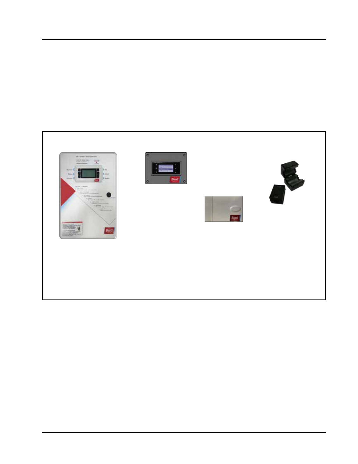
Controller
LV1000 controller and accessories included shown below.
LV1000 Series
TEC-EYETM Hand-Held
Diagnostic Tool
Bard P/N 8301-059
LV1000 Series
Programmable Logic
Controller
Remote Temperature/
Humidity Sensor*
(with 35' shielded cable)
Bard P/N 8403-079
* One remote temperature/humidity sensor and 35' of shielded cable are included with the LV1000 controller.
Up to two additional remote temperature/humidity sensors can be purchased and installed. Temperature-only
sensors (Bard P/N 8301-058) may be used instead of the additional temperature/humidity sensors, but will
also need to be purchased separately.
The equipment covered in this manual is to be installed
by trained, experienced service and installation
technicians.
These instructions should be carefully read before
beginning the installation. Note particularly any tags
and/or labels attached to the equipment.
While these instructions are intended as a general
recommended guide, they do not supersede any national
and/or local codes in any way. Authorities having
jurisdiction should be consulted before the installation is
made. See Additional Publications for information
on codes and standards.
Shipping Damage
Upon receipt of equipment, the cartons should be
checked for external signs of shipping damage. If
damage is found, the receiving party must contact
the last carrier immediately, preferably in writing,
requesting inspection by the carrier’s agent.
Additional Publications
These publications can help when installing the
furnace. They can usually be found at the local library
or purchased directly from the publisher. Be sure to
consult the current edition of each standard.
National Electrical Code ...................... ANSI/NFPA 70
Standard for the Installation of Air Conditioning
and Ventilating Systems ...................ANSI/NFPA 90A
Standard for Warm Air Heating
and Air Conditioning Systems ............ANSI/NFPA 90B
Communication
EMI Filters
Bard P/N 8301-055
Page 3 of 36
Load Calculation for Residential Winter
and Summer Air Conditioning ............. ACCA Manual J
Duct Design for Residential Winter and Summer
Air Conditioning and Equipment Selection
....................................................... ACCA Manual D
For more information, contact these publishers:
Air Conditioning Contractors of America (ACCA)
1712 New Hampshire Ave. N.W.
Washington, DC 20009
Telephone: (202) 483-9370 Fax: (202) 234-4721
American National Standards Institute (ANSI)
11 West Street, 13th Floor
New York, NY 10036
Telephone: (212) 642-4900 Fax: (212) 302-1286
American Society of Heating, Refrigeration and Air
Conditioning Engineers, Inc. (ASHRAE)
1791 Tullie Circle, N.E.
Atlanta, GA 30329-2305
Telephone: (404) 636-8400 Fax: (404) 321-5478
National Fire Protection Association (NFPA)
Batterymarch Park
P. O. Box 9101
Quincy, MA 02269-9901
Telephone: (800) 344-3555 Fax: (617) 984-7057
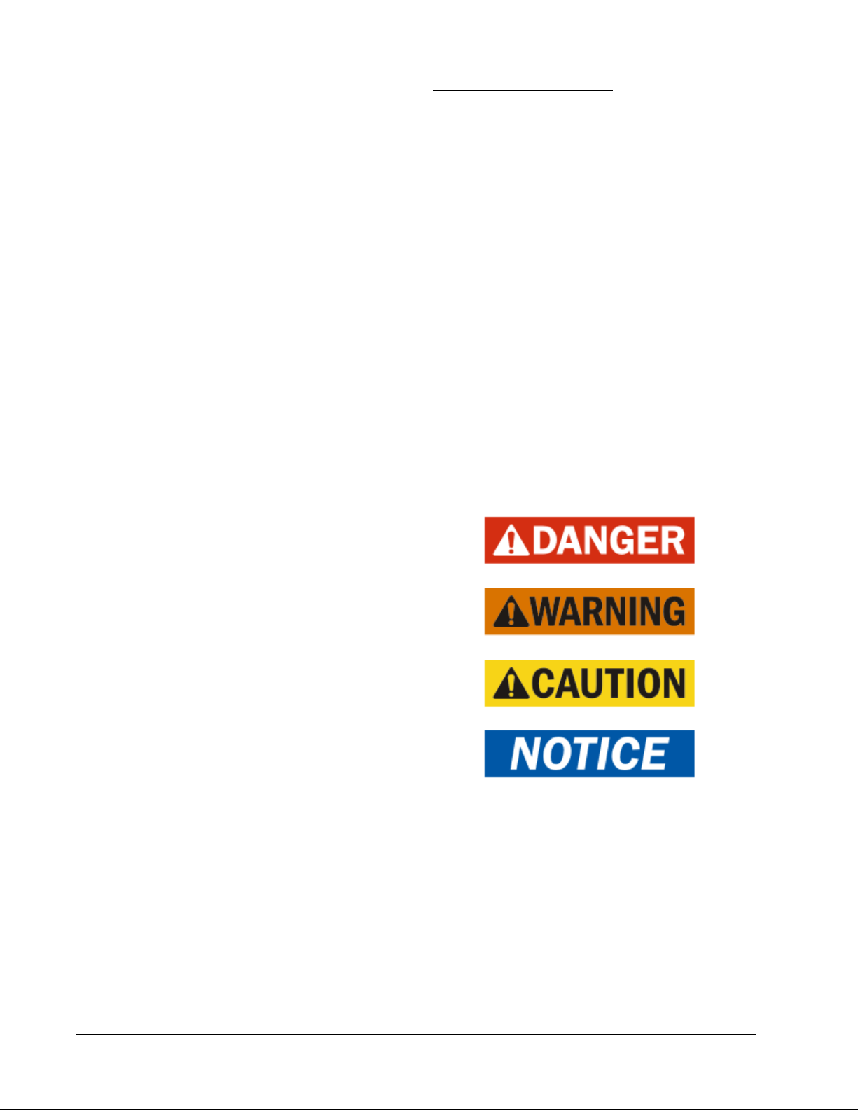
ANSI Z535.5 Definitions:
DANGER: Indicate[s] a hazardous situation which, if
not avoided, will result in death or serious injury. The
signal word “DANGER” is to be limited to the most
extreme situations. DANGER [signs] should not be used
for property damage hazards unless personal injury risk
appropriate to these levels is also involved.
WARNING: Indicate[s] a hazardous situation which,
if not avoided, could result in death or serious injury.
WARNING [signs] should not be used for property
damage hazards unless personal injury risk appropriate
to this level is also involved.
CAUTION: Indicate[s] a hazardous situation which, if
not avoided, could result in minor or moderate injury.
CAUTION [signs] without a safety alert symbol may be
used to alert against unsafe practices that can result in
property damage only.
NOTICE: [this header is] preferred to address practices
not related to personal injury. The safety alert symbol
shall not be used with this signal word. As an
alternative to “NOTICE” the word “CAUTION” without
the safety alert symbol may be used to indicate a
message not related to personal injury.
Page 4 of 36

SECTION 1:
INSTALLATION
INSTRUCTIONS
Page 5 of 36
LIST OF NECESSARY MATERIALS/TOOLS
Additional hardware and miscellaneous supplies are needed for installation. These items are field supplied and must
be sourced before installation. This list also includes tools needed for installation.
List of Materials/Tools
• Personal protective equipment/safety devices
• Miscellaneous hand and power tools and jobsite or
shop materials
• Electrical supplies:
- Circuit breaker for the shelter AC breaker
box (see unit electrical specifications for
requirements)
- 16 gauge minimum, 14 gauge maximum
power wire to connect controller to shelter
power source
- Communication wire: 2-wire, 18 gauge,
shielded with drain
- 5-wire, 18 gauge shielded cable with drain for
remote temperature and humidity sensors
- 18 gauge non-shielded wire for connecting
smoke detector, hydrogen detector and/or
generator, if applicable, to controller
-
- Miscellaneous electrical supplies including
- Fasteners appropriate for the shelter wall
CAT 6 Ethernet cable of field-determined length
(for remote communication, if applicable)
rigid/flexible conduit and fittings, 2" x 4"
junction boxes (one per temperature/humidity
sensor), wire connectors and supports
construction to attach the controller to the wall
The following is required and must be sourced prior
to installation of these units.
• One (1) 5A circuit breaker for the shelter DC
power plant (for the controller)
Circuit breakers for Emerson Network Power (ENP)
power plants (used in most telecomm shelters built
today) are available directly through the following
distributors:
• Emerson Network Power: 440.288.1122
• Master Electronics: 888.473.5297 or
www.onlinecomponents.com
Emerson Network Power (ENP) Part Number
• 5A circuit breaker: P/N 101598
Always confirm the application before ordering.
Page 6 of 36
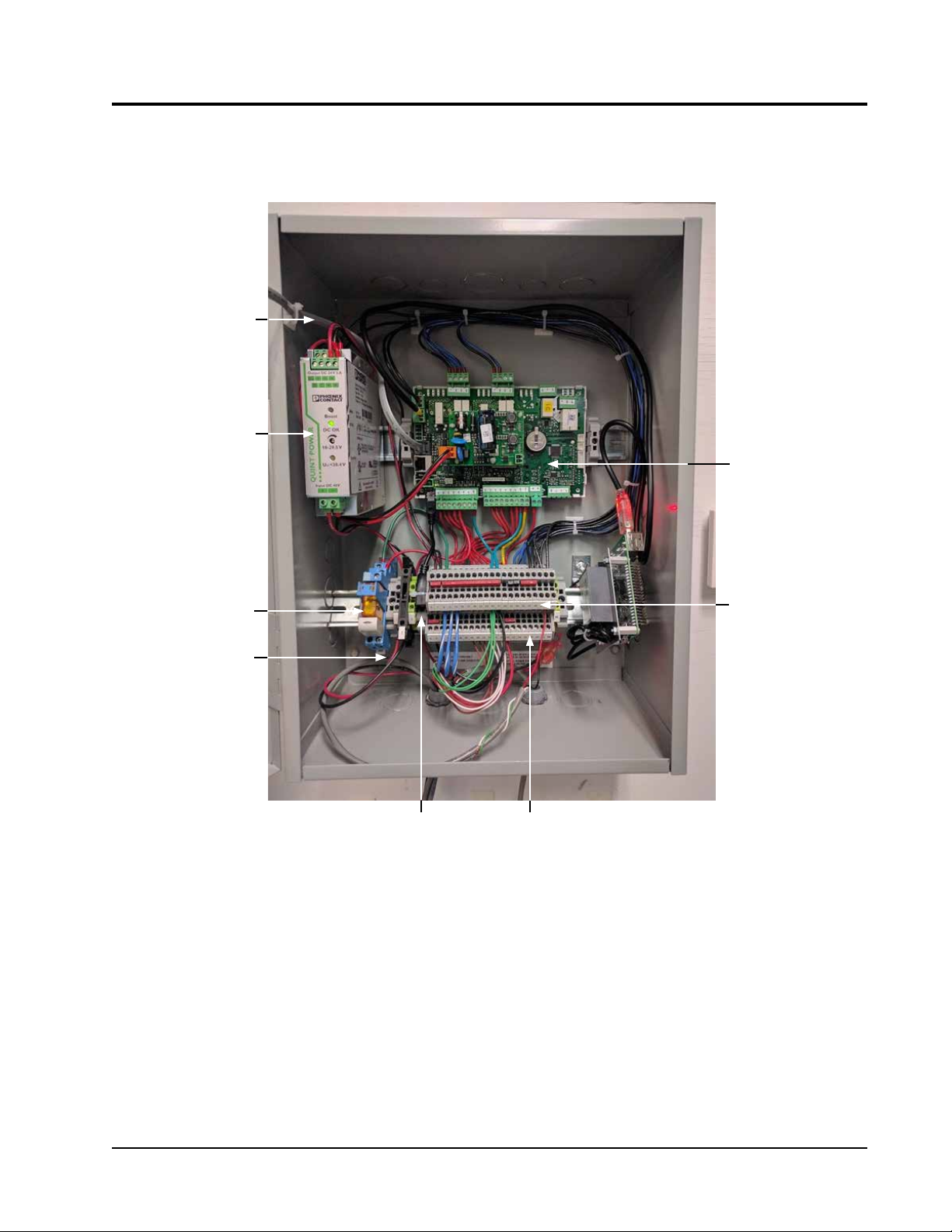
RJ11 Cable
to Display
-48VDC to 24V
Power Supply
LV1000 CONTROLLER INSTALLATION
FIGURE 1.1
Typical LV1000 Component Location
Control Board
Power Loss Relay
Power Supply
Connections
USB
Connection
Shelter Inputs
and Outputs
Terminal Block
Page 7 of 36
!
WARNING
Electrical shock hazard.
Disconnect VAC and VDC power supplies
before servicing.
Failure to do so could result in electric shock
or death.
LV1000 Controller
The LV1000 controller is part of the Free Cooling
Unit system by Bard. It is used to control up to four
(4) wall-mount air conditioners from one controller.
The microprocessor control provides an easy-to-read
interface with large LCD graphical display. It provides
control for redundancy for the structure and equal wear
on all units. The LV1000 controller is configured for
first on/next on sequence.
Conduit is recommended for all wiring. Route
communication wiring and power supply wiring in their
own separate conduits.
The LV1000 controller is not weatherproof and is
intended for use in weathertight structure.
1. Mounting the LV1000 Controller
Because the LV1000 controller utilizes a remote
temperature sensor as opposed to one located in the
controller box, the controller itself can be installed in
any indoor location that is suitable, preferably at eye
level. Four (4) mounting holes are provided for mounting
to the wall and holes for conduit connection are provided
in both the base, sides and top of the controller.
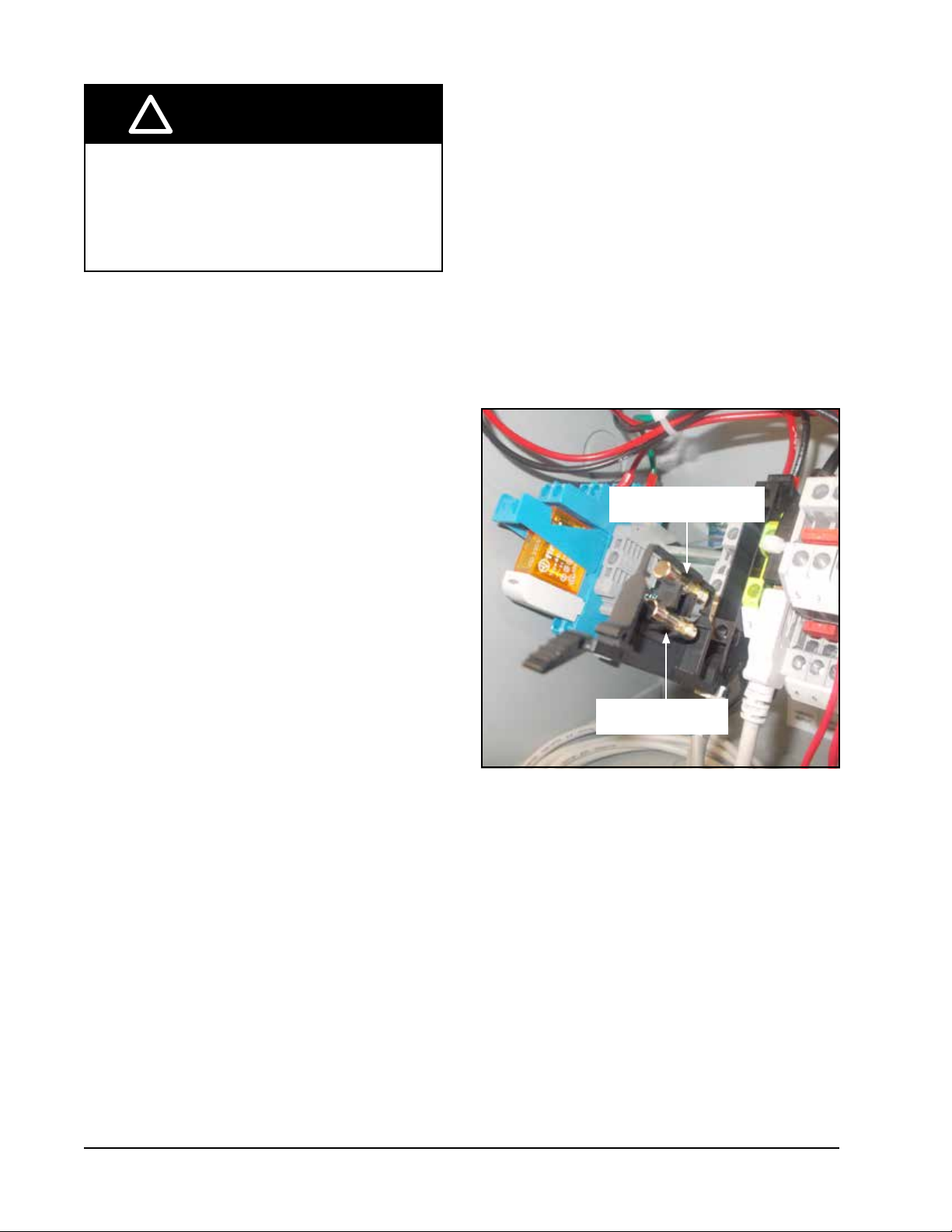
The LV1000 controller includes a fused power supply
terminal in the terminal block. Before connecting wires
to the terminal block, confirm that the fuse in the fuse
holder is in the proper position (active) as shown in
Figure 1.2.
FIGURE 1.2
LV1000 Fused Power Supply Terminal
Fuse in Active Position
Page 8 of 36
Shipping Position

2. Installing Remote Indoor Temperature/Humidity Sensor(s)
One remote indoor temperature/humidity sensor and 35' of 18 gauge shielded cable is included with the controller.
This sensor must be installed for proper operation. Mount the temperature/humidity sensor in a location least likely to
be affected by open doors, rack-mounted fans, radiant heat sources, etc. Location height should be approximately 60"
above the floor. The sensor should be installed on a 2" x 4" junction box to allow for control wire conduit (see Figure
1.3). Use shielded cable to connect to controller.
FIGURE 1.3
Remote Indoor Temperature/Humidity Sensor Installation
1. Connect wires from the 18 gauge shielded cable to terminals #24, #25, #18, #19 and #30.
TB#
Wire
Mark
Sensor Description
24 B6 NTC OUT Indoor Temperature 1
25 GND NTC OUT Ground
18 B2 OUT H Indoor Humidity 1 Signal: 0-1 VDC
19 GND M (G) Indoor Humidity 1 Common
30 +VDC + (G) Indoor Humidity 1 Power
4 5 7 8 9 10 11 12 13 14 15 16 17 18 19 20 21 22 23 24 25 26 27 28 29 30 31 32 33 34 35 36 37 38 39 40 41 42 43 44 45 466
2. Connect the other end of the shielded cable to the sensor
terminals. Be sure wires are connected to proper terminals
as shown in table above. Sensor jumpers need to be
positioned for 0-1 V. With sensor oriented as shown in
image to right, move both jumpers to left position (DP1 and
DP2 set to OFF).
This applies to all temperature/humidity sensors connected
to the LV controller.
Sensor is best mounted on a junction box, and it is
recommended that the cable be in conduit.
Jumper
DP1
DP2
Page 9 of 36
For proper operation, the remote indoor temperature/humidity sensor must be configured properly with the
controller. If only the single remote indoor temperature/humidity sensor supplied with the controller is installed,
the configuration setting is "0". This is the default setting. Up to two additional temperature and humidity sensors
can be purchased and installed. Alternately, temperature-only sensors can be purchased and installed instead of
the combination sensors. For information on remote indoor sensor configuration, see page 21.
Use shielded cable to
connect additional sensors to controller.
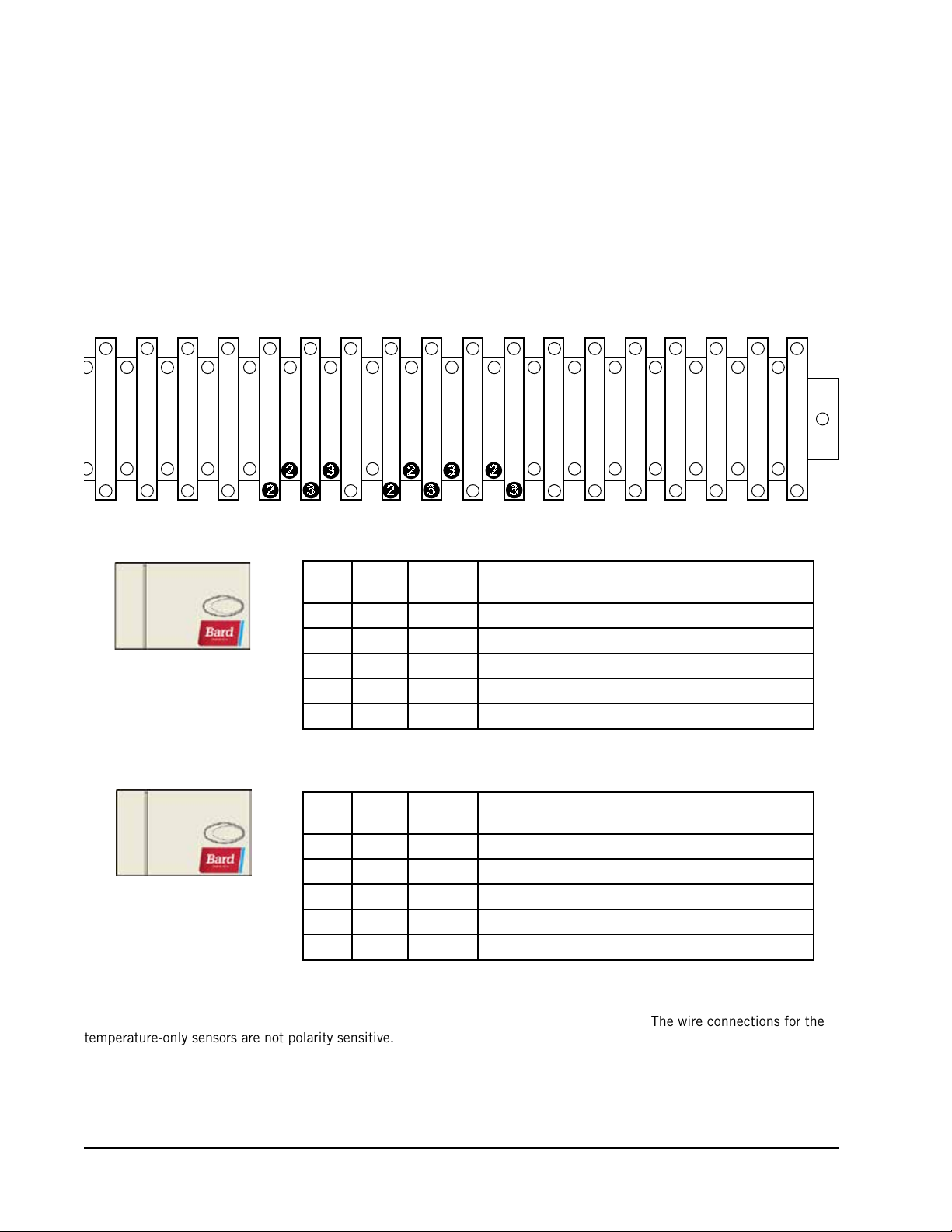
FIGURE 1.4
Additional Remote Temperature and Temperature/Humidity Sensor Installation
Up to two additional temperature/humidity sensors may be added. Be sure the sensors are connected to the proper
terminals on the terminal block and sensor as listed below. See page 9 for information on correct sensor jumper
position.
12 13 14 15 16 17 18 19 20 21 22 23 24 25 26 27 28 29 30 31 32 33 34 35 36 37 38 39 40 41 42 43 44 45 46
3 3
2
3
2
2
3
2
2
3
TB#
26 B7 NTC OUT Indoor Temperature 2
27 GND NTC OUT Ground
#2
Optional Remote
Temperature/Humidity Sensor
Terminals 26, 27, 20, 21 & 31
#3
Optional Remote
Temperature/Humidity Sensor
Terminals 28, 29, 22, 23 & 32
Temperature-only sensors can be used in place of the additional temperature/humidity sensors. #2 temperature-only sensor
will connect to TB# 26 and 27. #3 temperature-only sensor will connect to TB# 28 and 29. The wire connections for the
temperature-only sensors are not polarity sensitive.
20 B3 OUT H Indoor Humidity 2 Signal: 0-1 VDC
21 GND M (G) Indoor Humidity 2 Common
31 +VDC + (G) Indoor Humidity 2 Power
TB#
28 B8 NTC OUT Indoor Temperature 3
29 GND NTC OUT Ground
22 B4 OUT H Indoor Humidity 3 Signal: 0-1 VDC
23 GND M (G) Indoor Humidity 3 Common
32 +VDC + (G) Indoor Humidity 3 Power
Wire
Mark
Wire
Mark
Sensor Description
Sensor Description
Page 10 of 36
3. Additional LV1000 Connections
There are factory-installed jumpers across terminals #8 and #9 (smoke detector), #10 and #11 (hydrogen detector)
and #12 and #13 (generator run). Remove the factory-installed jumpers before connecting to the detectors and/or
generator (if applicable).
INPUTS
Smoke
Hydrogen
Generator
Anti-Theft
Power Loss
Humidifier
HVAC Fail
HVAC Maintenance
Anti-Theft
LV1000 Connections Sensor Connections
Wire Mark Terminal Terminal
DI1 8
GND 9 Ground
DI2 10 Hydrogen Detector Input
GND 11 Ground
DI3 12 Generator Run Input
GND 13 Ground
DI4 14 Anti-Theft Device
GND 15 Ground
Relay - A1 230VAC Power Loss Relay
Relay - A2 230VAC Power Loss Relay
wiring guideine in Figure x.x
Varies by sensor used. See general
Description
Smoke Detector Input
OUTPUTS
LV1000 Connections
Wire Mark Terminal Terminal
NO1 34
C1 35 Common
NO2 36 Alarm Relay – HVAC Fail
C1 37 Common
NO3 38
C1 39 Common
NO4 40 Alarm Relay – Anti-Theft
C2 41 Common
External
Connections
guideine in Figure x.x
Varies. See general wiring
Description
Humidifier Output
Alarm Relay –
HVAC Maintenance
Fieldbus 1*
Fieldbus 2*
Ground FB-2 (–) 46 Shield Shield for Daisy Chain
* Polarity Sensitive
COMMUNICATIONS
LV1000 Connections
Wire Mark Terminal Terminal
FB-1 (–) 42 1 Wall Unit Daisy Chain
FB-1 (+) 43 2 Wall Unit Daisy Chain
FB-2 (–) 44 – IPv6 SNMP Board
FB-2 (+) 45 + Ground
External
Connections
Description
Page 11 of 36

4. Communication Wiring
Connect the communication wiring from the wall-mount units to the controller in the manner shown in Figures 1.5,
1.6 or 1.7. The communication wire should be 2-wire, 18 gauge shielded cable with drain. Any color can be used.
Be sure to match "+" and "-" symbols on controller terminal blocks to prewired unit control terminal block (see
Figures 1.9 and 1.10 on pages 15 and 16). Attach communication wire filters as shown in Figures 1.5, 1.6 or 1.7.
Filters go inside the unit or controller box; they are shown out of unit for identification purposes only. Do not run
communication wiring in same conduit as supply wiring.
Route communication wiring and power supply wiring in
their own separate conduits.
FIGURE 1.5
Communication Wiring (Daisy Chain Method)
Wall-Mount Unit
Filter
Wall-Mount Unit
Filter
LV1000 Controller
In addition to the "daisy chain" method of connecting the communication wiring shown in Figure 1.5, the wall-mount
units can also be connected in the manner shown in Figure 1.6. If connecting wall-units this way, be sure to place
the communication wire filters in the positions shown in Figure 1.6. See Figure 1.7 for more information on the
correct placement of the communication wire filters depending on the wiring method used.
FIGURE 1.6
Communication Wiring (Alternate Method)
Wall-Mount Unit
Page 12 of 36
LV
Controller
Filter
Filter
Wall-Mount Unit

FIGURE 1.7
Placement of Communication Wire Filters (Daisy Chain and Alternate Methods)
Daisy Chain Wiring (up to four units)
Place filter here
LV1000
Place filter here
Place filter here
Unit 1 Unit 2 Unit 3 Unit 4
Alternate Wiring (up to four units)
Place filter here
LV1000*
Unit 1 Unit 2 Unit 3 Unit 4
* LV1000 can be in any position other than start and end
NOTE: Line filters can be on either the unit or controller, whichever device is on the end of the chain. No matter
how many units there are, the two end devices will only have ONE communication cable, whereas the
center devices will all have TWO (as shown above). Filters go inside the unit or controller; shown out of
unit above for identification only.
Page 13 of 36

The steps outlined on the following pages show how to connect the communication wiring using the daisy chain
- +
G
method shown in Figure 1.5. If using the alternate method (as shown in Figure 1.6), the connections to the
controller and each wall-mount unit will be the same but the filters need to be placed in the positions shown in
Figure 1.7.
FIGURE 1.8
Communication Wiring: Termination at the Controller
1. Using the field-provided shielded cable, make a small service loop after entering the controller and attach the provided
EMI filter at the intersection of the loop.
2. Connect one wire to terminal #44 (NEGATIVE), the other wire to terminal #45 (POSITIVE) and the drain wire to
ground terminal #46.
20 21 22 23 24 25 26 27 28 29 30 31 32 33 34 35 36 37 38 39 40 41 42 43 44 45 46
To Wall-Mount Unit 1
Control Board RS485
Page 14 of 36
NOTE: The drain only gets grounded one time,
anywhere in the chain.

FIGURE 1.9
Communication Wiring: Termination at the First Wall-Mount Unit
1 2 4 5 7 9 108 12 14 16 173 6
Unit 1 Terminal Block
13 15
11
– +
From LV1000
Controller
1. From the controller, extend the shielded cable through a separate conduit
and route to the provided terminal block next to the wall-mount control
board.
Note that the terminal block label is clearly marked “+” and “-”. These
connections are polarity-sensitive. Two-wire communication from control
board is prewired to terminal block. Make sure to match "+" and "-"
symbols on controller terminal block.
Wall-Mount Unit 1
2. Connect the wires matching the terminal
designations (+/-) of the controller
terminals. Leave the drain wire loose.
3. Connect another cable in a similar
fashion (“daisy chain”) to route in
conduit to the second wall-mount unit.
Connect both drain wires with wire nut.
1 2 4 5 7 9 108 12 14 16 173 6
– +
1 2 4 5 7 9 108 12 14 16 173 6
– +
13 15
Unit 1 Terminal Block
Unit 1 Terminal Block
11
From LV1000
Controller
13 15
11
From LV1000
Controller
To Wall-Mount Unit 2
Page 15 of 36

FIGURE 1.10
Communication Wiring: Termination at Additional Wall-Mount Units
1 2 4 5 7 9 108 12 14 16 173 6
Unit 2 Terminal Block
13 15
11
– +
From Wall-Mount
Unit 1
1. Route the cable from the first wall-mount unit to the
terminal block of the second wall-mount unit. If this is
the last unit to be connected, make a small service loop
and attach EMI filter as shown.
2. Connect the wires matching the terminal
designations (+/-) of the controller terminals.
Cap the loose drain with a wire nut or
electrical tape.
1 2 4 5 7 9 108 12 14 16 173 6
– +
Wall-Mount Unit 2
13 15
Unit 2 Terminal Block
11
From Wall-Mount
Unit 1
3. Continue daisy chaining units by connecting
"+" to "+", "-" to "-" and wire nutting drain
together until last unit which is capped with
a wire nut. Attach EMI filter as shown above
at last unit. Up to four wall-mount units can
be connected and controlled by one LV1000
controller.
Page 16 of 36

5. Supply Wiring
1 2 3 4 5 7 8 9 10 11 12 13 14 15 16 17 18 19 20 21 22 23 24 25 26 27 28 29 30 31 32 33 34 35 36 37 38 39 40 41 42 43 44 45 466
The LV1000 controller is powered by -48VDC from the shelter. A field-supplied 5 amp DC circuit breaker is required.
Field-supplied supply wiring should be minimum 16 gauge, maximum 14 gauge (see Figure 1.11). A reliable
earth ground must be connected in addition to any grounding from conduit. Grounding posts are included with the
controller for this purpose; install as shown in Figure 1.12. Failing to ground the controller box properly could result
in damage to the equipment.
FIGURE 1.11
LV1000-100 Controller Supply Wiring
The controller requires a separate -48VDC power supply, an additional 5-amp DC breaker (field supplied) and minimum 16
gauge supply wire.
-48VDC termination at controller: Bring the -48VDC power supply wires through conduit to the controller box. Land the
positive (+) 48VDC wire to terminal #1 and the negative (-) 48VDC wire to terminal #2.
NOTE: If the DC wiring is not terminated correctly on the specific polarity-indicated terminals of the
block, the controller will not activate and will not function. Verify polarity of connections and wait to
initialize controller until "system start up."
+
–
FIGURE 1.12
Controller Grounding Posts
A reliable earth ground must be connected in
addition to any grounding from conduit. Attach
earth ground to dedicated lugs on side of controller
box. Failing to ground the controller box properly
could result in damage to the equipment.
Page 17 of 36

TABLE 1.1
Terminal Block Index
TB#
10 DI2 Hydrogen Detector Input
11 GND Hydrogen Detector Common
12 DI3 Generator Run Input
13 GND Generator Run Common
14 DI4 Anti Theft Input
15 GND Anti Theft Common
16 - RESERVED FOR POWER LOSS INPUT
17 GND
18 B2 Humidity Sensor 1
19 GND Ground
20 B3 Humidity Sensor 2
21 GND Ground
22 B4 Humidity Sensor 3
23 GND Ground
Wire
Mark
1 48+ 48VDC +Input
2 48– 48VDC – Input
3 - Ground
4 - 24VDC +
5 - 24VDC –
6 24+ 24VDC +
7 24– 24VDC –
8 DI1 Smoke Detector Input
9 GND Smoke Detector Common
RESERVED FOR POWER LOSS INPUT –
COMMON
Description
TB#
24 B6 Temperature Sensor 1
25 GND Ground
26 B7 Temperature Sensor 2
27 GND Ground
28 B8 Temperature Sensor 3
29 GND Ground
30 VDC+ Sensor Power Distribution
31 VDC+ Sensor Power Distribution
32 VDC+ Sensor Power Distribution
33 VDC+ Sensor Power Distribution
34 NO1 Humidifier Output Relay
35 C1 Common
36 NO2 HVAC Fail
37 C1 Common
38 NO3 HVAC Maintenance
39 C1 Common
40 NO4 HVAC Anti Theft
41 C2 Common
42 FB1R- RS485 RX- / TX- (Fieldbus 1)
43 FB1R+ RS485 RX+ / TX+ (Fieldbus 1)
44 FB2R- RS485 RX- / TX- (Fieldbus 2)
45 FB2R+ RS485 RX+ / TX+ (Fieldbus 2)
46 - Ground Communication Shield
Wire
Mark
Description
Page 18 of 36

FIGURE 1.13
LV1000 Wiring Diagram
Page 19 of 36

SYSTEM START-UP
Before the Bard Free Cooling Unit system can be set up
for operation, each wall-mount unit must have already
been installed, given a unique address and had a run
test performed (see FUSION-TEC manual 2100-670).
After those procedures have been completed with each
unit, the system start-up can proceed.
The LV1000 controller will be used to set up the Bard
Free Cooling Unit system.
LV1000 Controller
The microprocessor control used in the FUSIONTEC wall-mount air conditioners allows for complete
control and monitoring through the use of the LV1000
controller.
The menu driven interface provides users the ability
to scroll through two menu levels: Quick Menu and
Main Menu. The menus permit the user to easily view,
control and configure the wall-mount unit system.
The controller is completely programmed at the factory;
the default setpoints and their ranges are easily
viewed and adjusted from the controller display. The
program and operating parameters are permanently
stored on FLASH-MEMORY in case of power failure.
The controller is designed to manage temperature and
humidity levels to a user-defined setpoint via control
output signals to the wall-mount air conditioning
system.
The TEC-EYETM diagnostic tool is shipped inside the
controller. See FUSION-TEC manual 2100-670 for
more information on using the TEC-EYETM.
LV1000 Menu Structure
Quick Menu
Data Log
Unit Information
Setpoints
Main Menu
System Configuration
Advanced System Configuration
I/O Configuration
On/Off
Alarm Logs
Settings
Logout
In addition to the menu structure above, there are also
Status and Alarm screens.
Interface Acronyms
MAT – Mixed air temperature
RAT – Return air temperature
SAT – Supply air temperature
OAT – Outdoor air temperature
OAH – Outdoor air humidity
Blower – Indoor Blower Status
Damper – Free cooling damper position status
ALARM KEY
MENU KEY
ESCAPE KEY
TEC-EYETM interface key functions are the same as above.
ALARM KEY
Allows viewing of active alarms
Silences audible alarms
Resets active alarms
MENU KEY
Allows entry to Main Menu
FIGURE 1.14
LV1000 Controller Display and Interface
ESCAPE KEY
Returns to previous menu level
Cancels a changed entry
UP KEY
Steps to next screen in the display
menu
Changes (increases) the value of a
modifiable field
UP KEY
ENTER KEY
DOWN KEY
ENTER KEY
Accepts current value of a
modifiable field
Advances cursor
DOWN KEY
Steps back to previous screen in
the display menu
Changes (decreases) the value of
a modifiable field
Page 20 of 36

C1 – Compressor activate status
H1 – Heater Stage 1 status
H2 – Heater Stage 2 status
ODP – Calculated outdoor dew point
FC – Free cooling status
RN – Component run time in minutes in last hour
ST – Number of start requests in last hour
Status Screen
The Status screen is the default start-up screen and
also the return screen after 5 minutes of no activity
TM
on both the LV1000 and the TEC-EYE
. The screen
can be accessed any time by pressing the ESCAPE key
repeatedly.
The Status screen on the LV1000 displays the current
date, time, indoor average temperatue and humidity,
lead unit and system status (see Figure 1.14).
Quick Menu
The Quick Menu is accessible from the Status screen
TM
on both the LV1000 and TEC-EYE
. Data Log, Unit
Information and Setpoints are available through the
Quick Menu. Pressing the UP or DOWN keys while on
the Status screen will change the Quick Menu icon
displayed (see Figure 1.15). Press the ENTER key
when the desired icon is displayed.
See page 36 for additional information on the three
Quick Menu options.
FIGURE 1.15
Quick Menu Icons
Data Log Unit Information
Setpoints
SYSTEM SET-UP
Use the LV controller to set-up the Bard Free Cooling
Unit system.
1. Set LV Controller Date and Time
1) Press MENU key to access the Main Menu
screen.
2) Press UP or DOWN keys and ENTER key to
enter USER password 2000.
3) Press the UP or DOWN keys to scroll to the
Settings; press ENTER key.
4) Press UP or DOWN keys to scroll to Date/Time
Change; press ENTER key.
5) Press ENTER key to scroll to the desired value
to be changed (see Figure 1.16).
6) Press UP or DOWN keys to change the value.
7) Press the ESCAPE key several times to return
to Main Menu screen.
FIGURE 1.16
Setting Controller Date and Time
2. Configure Sensors
The system will need to be configured for the
number of temperature and humidity sensors
installed. The system is shipped with one
combination temperature and humidity sensor.
Additional combination sensors may be purchased
or althernatively, temperature-only sensors may be
purchased instead. The LV is capable of utilizing
three temperature sensors and three humidity
sensors. The system will need to be configured for
the various configurations.
If necessary, the sensors could be calibrated at
this time too. For information on calibrating the
sensors, see page 36.
To enable/disable Indoor Humidity 1:
1) Press MENU key to go to the Main Menu
screen.
2) Press UP or DOWN keys and ENTER key to
enter USER password 2000.
3) Press UP or DOWN keys to scroll to IO Config;
press ENTER key.
4) Press UP or DOWN keys to scroll to Indoor
Humidity 1 (C3).
5) Press ENTER key to scroll to Enable (see
Figure 1.17).
6) Press UP or DOWN key to change value to ON
to enable sensor (or change value to OFF to
disable sensor).
FIGURE 1.17
Configuring Indoor Humidity 1 Sensor
Page 21 of 36

To enable/disable Indoor Humidity 2:
1) Press MENU key to go to the Main Menu
screen.
2) Press UP or DOWN keys and ENTER key to
enter USER password 2000.
3) Press UP or DOWN keys to scroll to IO Config;
press ENTER key.
4) Press UP or DOWN keys to scroll to Indoor
Humidity 2 (C4).
5) Press ENTER key to scroll to Enable (see
Figure 1.18).
6) Press UP or DOWN key to change value to ON
to enable sensor (or change value to OFF to
disable sensor).
FIGURE 1.18
Configuring Indoor Humidity 2 Sensor
FIGURE 1.19
Configuring Indoor Humidity 3 Sensor
To enable/disable Indoor Temperature 1:
1) Press MENU key to go to the Main Menu
screen.
2) Press UP or DOWN keys and ENTER key to
enter USER password 2000.
3) Press UP or DOWN keys to scroll to IO Config;
press ENTER key.
4) Press UP or DOWN keys to scroll to Indoor
Temperature 1 (C6).
5) Press ENTER key to scroll to Enable (see
Figure 1.20).
6) Press UP or DOWN key to change value to ON
to enable sensor (or change value to OFF to
disable sensor).
To enable/disable Indoor Humidity 3:
1) Press MENU key to go to the Main Menu
screen.
2) Press UP or DOWN keys and ENTER key to
enter USER password 2000.
3) Press UP or DOWN keys to scroll to IO Config;
press ENTER key.
4) Press UP or DOWN keys to scroll to Indoor
Humidity 3 (C5).
5) Press ENTER key to scroll to Enable (see
Figure 1.19).
6) Press UP or DOWN key to change value to ON
to enable sensor (or change value to OFF to
disable sensor).
FIGURE 1.20
Configuring Indoor Temperature 1 Sensor
To enable/disable Indoor Temperature 2:
1) Press MENU key to go to the Main Menu
screen.
2) Press UP or DOWN keys and ENTER key to
enter USER password 2000.
3) Press UP or DOWN keys to scroll to IO Config;
press ENTER key.
4) Press UP or DOWN keys to scroll to Indoor
Temperature 2 (C7).
5) Press ENTER key to scroll to Enable (see
Figure 1.21).
Page 22 of 36

6) Press UP or DOWN key to change value to ON
to enable sensor (or change value to OFF to
disable sensor).
FIGURE 1.21
Configuring Indoor Temperature 2 Sensor
To enable/disable Indoor Temperature 3:
1) Press MENU key to go to the Main Menu
screen.
2) Press UP or DOWN keys and ENTER key to
enter USER password 2000.
3) Press UP or DOWN keys to scroll to IO Config;
press ENTER key.
4) Press UP or DOWN keys to scroll to Indoor
Temperature 3 (C8).
5) Press ENTER key to scroll to Enable (see
Figure 1.22).
6) Press UP or DOWN key to change value to ON
to enable sensor (or change value to OFF to
disable sensor).
FIGURE 1.22
Configuring Indoor Temperature 3 Sensor
3. Enter Total Units
1) Press MENU key to go to the Main Menu
screen.
2) Press UP or DOWN keys and ENTER key to
enter USER password 2000.
3) Press UP or DOWN keys to scroll to Sys Config;
press ENTER key.
4) Press UP or DOWN keys to scroll to Unit Setup
(A1); press ENTER key.
5) Press ENTER key to scroll to Total Units (see
Figure 1.23).
6) Press UP or DOWN keys to adjust value to
correct number of units.
7) Press ENTER key to save value.
NOTE: The cooling and heating setpoints are also
displayed on the Unit Setup (A1) screen.
See Temperature Control (beginning on
page 32) for information on adjusting the
cooling and heating setpoints.
8) Press the ESCAPE key several times to return
to Main Menu screen.
FIGURE 1.23
Entering Total Number of Units
4. Verify Units Are Online
Once a unit is uniquely addressed, communication
can be verified at the LV controller.
With the correct number of units set at the LV
controller, each unit can be remotely viewed from
the controller information screen.
To view these screens:
1) Press
2) Press UP or DOWN key until the Quick Menu in
3) Press UP or DOWN keys to scroll through the
In addition to being able to remotely view the units,
an alarm will be generated on the LV controller for
units not communicating.
ESCAPE
(May need to be pressed more than once.)
the lower right corner of the screen displays the
Information icon ( ); press ENTER key.
information screens until the desired unit
information screen appears (see Figure 1.24 on
page 24).
key to view the Status screen.
Page 23 of 36

FIGURE 1.24
Verifying Units
5. Complete Installation
Once all the installation steps have been
completed, all alarms have been cleared and
system verification and run test results were
satisfactory, the installation can now be considered
“complete".
Additional programming information can be found
in the Service Instructions section of this manual.
Page 24 of 36

SECTION 2:
SERVICE
INSTRUCTIONS
Page 25 of 36

ALARMS
Quick Menu
Alarm Adjustment
Acknowledging/Clearing Alarms
Alarm conditions activate a red LED indicator that
backlights the ALARM function key. As an option, an
alarm condition may also be enunciated by an audible
alarm signal. An alarm is acknowledged by pressing the
ALARM key. This calls up alarm display screen(s) that
provide a text message detailing the alarm condition(s).
After an alarm condition is corrected, the alarm can be
cleared by pressing the ALARM key for 3 seconds.
Sensor Failure Alarms
The controller is capable of determining if a sensor has
failed. If the temperature or humidity measurement
is outside the following ranges, the controller will
consider the sensor as failed.
TABLE 2.1
Temperature and Humidity Sensors
Sensor Range
Indoor Temperature 1 -41°F to 303°F
Indoor Temperature 2 -41°F to 303°F
Indoor Temperature 3 -41°F to 303°F
Indoor Humidity 1 0-100%
Indoor Humidity 2 0-100%
Indoor Humidity 3 0-100%
Low Temperature Alarm
The LV will indicate a low temperature alarm when
any of the connected sensors that are enabled read a
value below the low temperature limit of 45°F. This
alarm does not use the average of the sensors like other
functions do.
To adjust the low temperature alarm setpoint:
1. Press MENU key to go to the Main Menu screen.
2. Use UP or DOWN keys and ENTER key to enter
USER password 2000.
3. Press UP or DOWN keys to scroll to Sys Config;
press ENTER key.
4. Press UP or DOWN keys to scroll to Alarm
Setpoints (A4).
5. Press ENTER key to scroll to Low Temp (see Figure
2.1).
6. Press UP or DOWN keys to adjust setpoint.
FIGURE 2.1
Adjusting Alarm Setpoints
The trigger type for the low temperature, high
temperature and high temperature 2 alarms can be
changed to reference the displayed average or the
lowest value (for low temperature alarm) and the
highest value (for high temperature alarms).
To adjust the low temperature alarm trigger type:
1. Press MENU key to go to the Main Menu screen.
2. Use UP or DOWN keys and ENTER key to enter
USER password 2000.
3. Press UP or DOWN keys to scroll to Sys Config;
press ENTER key.
4. Press UP or DOWN keys to scroll to Alarm
Setpoints (A4).
5. Press ENTER key to scroll to Trigger Type (see
Figure 2.1).
6. Press UP or DOWN keys to change from Hi/Low to
Average.
A delay of 10 seconds is applied to each alarm. This
can be adjusted by:
1. Press MENU key to go to the Main Menu screen.
2. Use UP or DOWN keys and ENTER key to enter
USER password 2000.
3. Press UP or DOWN keys to scroll to Sys Config;
press ENTER key.
4. Press UP or DOWN keys to scroll to Alarm
Setpoints (A4).
5. Press ENTER key to scroll to Alarm Delay (see
Figure 2.1).
6. Press UP or DOWN keys to adjust the delay.
High Temperature Alarm
The LV will indicate a high temperature alarm when
any of the connected sensors that are enabled read a
value above the high temperature limit of 85°F. This
alarm does not use the average of the sensors like other
functions do.
Page 26 of 36

To adjust the high temperature alarm setpoint:
1. Press MENU key to go to the Main Menu screen.
2. Use UP or DOWN keys and ENTER key to enter
USER password 2000.
3. Press UP or DOWN keys to scroll to Sys Config;
press ENTER key.
4. Press UP or DOWN keys to scroll to Alarm
Setpoints (A4).
5. Press ENTER key to scroll to High Temp (see
Figure 2.1).
6. Press UP or DOWN keys to adjust setpoint.
The trigger type for the low temperature, high
temperature and high temperature 2 alarms can be
changed to reference the displayed average or the
lowest value (for low temperature alarm) and the
highest value (for high temperature alarms).
To adjust the low temperature alarm trigger type:
1. Press MENU key to go to the Main Menu screen.
2. Use UP or DOWN keys and ENTER key to enter
USER password 2000.
3. Press UP or DOWN keys to scroll to Sys Config;
press ENTER key.
4. Press UP or DOWN keys to scroll to Alarm
Setpoints (A4).
5. Press ENTER key to scroll to Trigger Type (see
Figure 2.1).
6. Press UP or DOWN keys to change from Hi/Low to
Average.
A delay of 10 seconds is applied to each alarm. This
can be adjusted by:
1. Press MENU key to go to the Main Menu screen.
2. Use UP or DOWN keys and ENTER key to enter
USER password 2000.
3. Press UP or DOWN keys to scroll to Sys Config;
press ENTER key.
4. Press UP or DOWN keys to scroll to Alarm
Setpoints (A4).
5. Press ENTER key to scroll to Alarm Delay (see
Figure 2.1).
6. Press UP or DOWN keys to adjust the delay.
High Temperature 2 Alarm
The LV will indicate a high temperature 2 alarm when
any of the connected sensors that are enabled read a
value above the high temperature 2 limit of 90°F. This
alarm does not use the average of the sensors like other
functions do. In addition to the alarm being generated,
this event will put the system into emergency mode.
See emergency mode for more information.
To adjust the high temperature 2 alarm setpoint:
1. Press MENU key to go to the Main Menu screen.
2. Use UP or DOWN keys and ENTER key to enter
USER password 2000.
3. Press UP or DOWN keys to scroll to Sys Config;
press ENTER key.
4. Press UP or DOWN keys to scroll to Alarm
Setpoints (A4).
5. Press ENTER key to scroll to High Temp 2 (see
Figure 2.1).
6. Press UP or DOWN keys to adjust setpoint.
The trigger type for the low temperature, high
temperature and high temperature 2 alarms can be
changed to reference the displayed average or the
lowest value (for low temperature alarm) and the
highest value (for high temperature alarms).
To adjust the low temperature alarm trigger type:
1. Press MENU key to go to the Main Menu screen.
2. Use UP or DOWN keys and ENTER key to enter
USER password 2000.
3. Press UP or DOWN keys to scroll to Sys Config;
press ENTER key.
4. Press UP or DOWN keys to scroll to Alarm
Setpoints (A4).
5. Press ENTER key to scroll to Trigger Type (see
Figure 2.1).
6. Press UP or DOWN keys to change from Hi/Low to
Average.
A delay of 10 seconds is applied to each alarm. This
can be adjusted by:
1. Press MENU key to go to the Main Menu screen.
2. Use UP or DOWN keys and ENTER key to enter
USER password 2000.
3. Press UP or DOWN keys to scroll to Sys Config;
press ENTER key.
4. Press UP or DOWN keys to scroll to Alarm
Setpoints (A4).
5. Press ENTER key to scroll to Alarm Delay (see
Figure 2.1).
6. Press UP or DOWN keys to adjust the delay.
Smoke Alarm
The LV will indicate a smoke alarm when the smoke
detector input indicates there is smoke present in the
shelter. This input is enabled by default but comes
from the factory with a jumper. To utilize this input,
remove the jumper and connect the sensor in place
of the jumper. The alarm will communicate this
information to all of the wall units. The wall units will
be disabled so that no operations occur. See smoke
Page 27 of 36

alarm installation instructions for specific wiring
information. This alarm will automatically clear when
the smoke detector no longer indicates smoke is
present.
To change the smoke inputs:
1. Press MENU key to go to the Main Menu screen.
2. Use UP or DOWN keys and ENTER key to enter
USER password 2000.
3. Press UP or DOWN keys to scroll to IO Config;
press ENTER key.
4. Press UP or DOWN keys to scroll to Digital In
Config (C1).
5. Press ENTER key to scroll to the variable in the
table that intersects Smoke and Dir (see Figure
2.2).
6. Press UP or DOWN key to change direction.
7. Press ENTER key to save the value and move
cursor to variable in the table that intersects
Smoke and En.
8. Press UP or DOWN keys to change the value from
ON to OFF.
FIGURE 2.2
Changing Input Values
Hydrogen Alarm
The LV will indicate a hydrogen alarm when the
hydrogen detector indicates high levels of hydrogen
inside the shelter. This input is enabled by default
but comes with a factory-installed jumper. To utilize
this input, remove the jumper and connect the sensor
in place of the jumper. In addition to the alarm
being generated, this event will put the system into
emergency mode. See emergency mode for more
information. This alarm will automatically clear when
the hydrogen detector no longer indicates hydrogen is
present.
To change the smoke inputs:
1. Press MENU key to go to the Main Menu screen.
2. Use UP or DOWN keys and ENTER key to enter
USER password 2000.
3. Press UP or DOWN keys to scroll to IO Config;
press ENTER key.
4. Press UP or DOWN keys to scroll to Digital In
Config (C1).
5. Press ENTER key to scroll to the variable in the
table that intersects Hydro and Dir (see Figure
2.2).
6. Press UP or DOWN key to change direction.
7. Press ENTER key to save the value and move
cursor to variable in the table that intersects Hydro
and En.
9. Press UP or DOWN keys to change the value from
ON to OFF.
Generator Alarm
The LV will indicate a generator run alarm when the
generator run input indicates that the generator is
running. This input is enabled by default but comes
with a factory-installed jumper. To utilize this input,
remove the jumper and connect the generator in place
of the jumper.
To change the generator inputs:
1. Press MENU key to go to the Main Menu screen.
2. Use UP or DOWN keys and ENTER key to enter
USER password 2000.
3. Press UP or DOWN keys to scroll to IO Config;
press ENTER key.
4. Press UP or DOWN keys to scroll to Digital In
Config (C1).
5. Press ENTER key to scroll to the variable in the
table that intersects Gen and Dir (see Figure 2.2).
6. Press UP or DOWN key to change direction.
7. Press ENTER key to save the value and move
cursor to variable in the table that intersects Gen
and En.
8. Press UP or DOWN keys to change the value from
ON to OFF.
While the generator is running, the system will
only allow selected units to run. This selection is
customizable by the end user. This limitation is in
place to match the unit power requirements to the
shelter generator capacity.
The default for this setting is 1 unit is permitted to
run if 1, 2, or 3 is selected for the number of units
installed on the shelter. If the shelter is configured
for 4 units, the default will be 2 units. If a different
strategy is required, the end user can select which
units by address are allowed to run when the generator
run input is active.
Page 28 of 36

To change which units run when the generator run
input is active:
1. Press MENU key to go to the Main Menu screen.
2. Use UP or DOWN keys and ENTER key to enter
USER password 2000.
3. Press UP or DOWN keys to scroll to Adv System
Config; press ENTER key.
4. Press UP or DOWN keys to scroll to Unit Inhibit
(B3).
5. Press ENTER key to scroll to Unit 1 (see Figure
2.3).
6. Press UP or DOWN key to change Enabled on Gen
to Disabled on Gen.
7. Press ENTER key to save the value and move
cursor to Unit 2.
8. Press UP or DOWN keys and ENTER key to change
units to Disabled on Gen as needed.
FIGURE 2.3
Adjusting Units Running When Generator is Active
The system will also disable economizer operation
of all wall units when the generator is running. This
setting can be changed per wall unit by the end user
to allow the economizer to operate if the exhaust of the
generator is far enough away from the wall unit’s fresh
air intake.
To change which units can use the economizer when
the generator run input is active:
1. Press MENU key to go to the Main Menu screen.
2. Use UP or DOWN keys and ENTER key to enter
USER password 2000.
3. Press UP or DOWN keys to scroll to Adv System
Config; press ENTER key.
4. Press UP or DOWN keys to scroll to Econ Inhibit
(B2).
5. Press ENTER key to scroll to Unit 1 (see Figure
2.4).
6. Press UP or DOWN key to change Enabled on Gen
to Disabled on Gen.
7. Press ENTER key to save the value and move
cursor to Unit 2.
8. Press UP or DOWN keys and ENTER key to change
units to Disabled on Gen as needed.
This alarm will clear and operation will return to normal
when the generator run input no longer indicates the
generator is running.
FIGURE 2.4
Adjusting Economizers Running
When Generator is Active
Utility Power Loss Alarm
The LV will indicate a utility power loss alarm when
the power loss input indicates that utility power to the
shelter is not available. This can be accomplished in
two ways. The first way is with units equipped with the
inverter option; with these units, the wall unit controller
will detect a power loss and communicate the event
to the LV. The LV will then indicate a utility power loss
alarm. The second way is with wall units that do not
have the inverter option installed; with these units,
230v may be run into the LV enclosure and connected
to the power loss relay. When 230v is not present at the
power loss relay, the LV controller will indicate a utility
power loss alarm. When the power loss alarm is no
longer present from either the power loss relay in the LV
or the wall units, the alarm will automatically clear.
To change the power loss inputs:
1. Press MENU key to go to the Main Menu screen.
2. Use UP or DOWN keys and ENTER key to enter
USER password 2000.
3. Press UP or DOWN keys to scroll to IO Config;
press ENTER key.
4. Press UP or DOWN keys to scroll to Digital In
Config (C1).
5. Press ENTER key to scroll to the variable in the
table that intersects UtlPwr and Dir (see Figure
2.2).
6. Press UP or DOWN key to change direction.
7. Press ENTER key to save the value and move
cursor to variable in the table that intersects
UtlPwr and En.
Page 29 of 36

8. Press UP or DOWN keys to change the value from
OFF to ON.
HVAC Fail Alarm
The LV will monitor the wall units and if any of the
units communicate a high pressure or low pressure
event, each event will be displayed individually on the
LV. However, either of these alarms will open the alarm
relay for HVAC failure. This output is connected to the
NOC for remote notification. When all of these events
are no longer present, the alarm relay output will close
signaling there are no HVAC failure alarms.
The LV is will actuate a relay output when this alarm
occurs. The output is set up to open when an alarm
occurs by default. The direction of this alarm output
can be changed if required.
To change the direction of the HVAC fail alarm output:
1. Press MENU key to go to the Main Menu screen.
2. Use UP or DOWN keys and ENTER key to enter
USER password 2000.
3. Press UP or DOWN keys to scroll to IO Config;
press ENTER key.
4. Press UP or DOWN keys to scroll to Digital Out
Config (C2).
5. Press ENTER key to scroll to the variable in the
table that intersects HVACfail and Dir (see Figure
2.5).
6. Press UP or DOWN key to change direction.
FIGURE 2.5
Changing Output Values
Maintenance Alarm
The LV will monitor the wall units and if any of the
units communicate a dirty filter event or a dirty
condenser coil event, each of the alarms will be
displayed individually on the LV. However, either
of these alarms will trigger the alarm relay for
maintenance to open, which is connected to the NOC
for remote notification. When all of these events are
no longer present, the alarm relay output will close
signaling there are no HVAC maintenance alarms.
The LV is will actuate a relay output when this alarm
occurs. The output is set up to open when an alarm
occurs by default. The direction of this alarm output
can be changed if required.
To change the direction of the maintenance alarm
output:
1. Press MENU key to go to the Main Menu screen.
2. Use UP or DOWN keys and ENTER key to enter
USER password 2000.
3. Press UP or DOWN keys to scroll to IO Config;
press ENTER key.
4. Press UP or DOWN keys to scroll to Digital Out
Config (C2).
5. Press ENTER key to scroll to the variable in the
table that intersects HVACmaint and Dir (see
Figure 2.5).
6. Press UP or DOWN key to change direction.
Anti-Theft Alarm
The LV will indicate a theft alarm when the Bard Guard
anti-theft controller indicates an alarm to the antitheft input on the LV. This alarm will open an alarm
relay output to the NOC for remote notification. When
the input no longer indicates a theft, the alarm will
automatically clear and the alarm relay will return to its
normal state.
The LV is will actuate a relay output when this alarm
occurs. The output is set up to open when an alarm
occurs by default. The direction of this alarm output
can be changed if required. To change the output:
To change the anti-theft alarm inputs:
1. Press MENU key to go to the Main Menu screen.
2. Use UP or DOWN keys and ENTER key to enter
USER password 2000.
3. Press UP or DOWN keys to scroll to IO Config;
press ENTER key.
4. Press UP or DOWN keys to scroll to Digital In
Config (C1).
5. Press ENTER key to scroll to the variable in the
table that intersects Theft and Dir (see Figure 2.2
on page 28).
6. Press UP or DOWN key to change direction.
7. Press ENTER key to save the value and move
cursor to variable in the table that intersects Theft
and En.
8. Press UP or DOWN key to change the value from
OFF to ON.
Page 30 of 36

Humidifier Output
The LV has the option to control a humidifier through
a relay output. The output will close when a humidity
call from the LV is active and open when the call is
no longer present. The output can be configured to
operate in reverse where the contacts will open when a
humidity call is present and close when the call is no
longer present.
To change the direction of the humidifier output:
1. Press MENU key to go to the Main Menu screen.
2. Use UP or DOWN keys and ENTER key to enter
USER password 2000.
3. Press UP or DOWN keys to scroll to IO Config;
press ENTER key.
4. Press UP or DOWN keys to scroll to Digital Out
Config (C2).
5. Press ENTER key to scroll to the variable in the
table that intersects Hum and Dir (see Figure 2.5).
6. Press UP or DOWN key to change direction.
Page 31 of 36

CONTROL OPERATION
Temperature Control
Control Value Averaging
The system requires one temperature and humidity
sensor (included with LV) to operate. It allows a total
of three temperatures and three humidity sensors to
be connected to the LV for better representation of
what is happening in the shelter. When more than one
sensor is used, the value is averaged and then used for
temperature control operations and humidity control
operations.
Comfort Mode
The LV has a feature that allows a temporary override
of the temperature control settings. When “comfort
mode” is activated, the system will control to 72°F.
The system will stay in this mode for 60 minutes
and is intended to provide a more comfortable space
for a technician during a service call or scheduled
maintenance.
Emergency Mode
When the high temperature alarm 2 or the hydrogen
input indicate an alarm, the system will enter
emergency mode. The LV will communicate to each
wall unit that emergency mode is active. The wall units
will the override the damper position to 100% open
and turn the blower on. These two items will stay in
this state until both the high temperature alarm 2 and
the hydrogen detector are no longer in an alarm state.
Cooling
When the wall units are connected to the LV, the
economizer and compressor are commanded off and
on by the LV. This allows the supervisory controller to
consider the most effective and efficient order to bring
cooling functions on using all of the available equipment
installed on the shelter. At the same time the LV will be
able match the load requirements of the shelter.
To adjust the cooling setpoint:
1. Press MENU key to go to the Main Menu screen.
2. Press UP or DOWN keys and ENTER key to enter
USER password 2000.
3. Press UP or DOWN keys to scroll to Sys Config;
press ENTER key.
4. Press UP or DOWN keys to scroll to Unit Setup
(A1); press ENTER key.
5. Press ENTER key to scroll to Cooling (see Figure
2.6).
6. Press UP or DOWN keys to adjust value.
7. Press ENTER key to save.
8. Press the ESCAPE key several times to return to
Main Menu screen.
FIGURE 2.6
Adjusting Setpoints
The LV monitors the space temperature and compares
the value to the space cooling setpoint. The system will
compare how far above or below the space temperature
is when compared to the cooling setpoint. The LV will
also consider how long the shelter temperature has
been above or below the setpoint. Using these two
considerations, the controller will generate a cooling
demand. The cooling demand is a value between 0 and
100%. 0% represents no cooling demand and 100%
representing full cooling demand.
The system will consider all of the available cooling
stages and distribute the number of stages across
the cooling demand range. As the demand rises, the
system will stage on equipment every 2 minutes. As the
demand lowers, the system will stage off equipment
every 2 minutes.
The system will stage the equipment on in the order
shown in Table 2.2.
The system is also capable of rotating the order
in which the units are brought on. This is done to
distribute the equipment run time to each unit. This
prevents one unit from providing all of the cooling for
the shelter and shorting the lifespan of the wall unit.
The system is set to switch the unit staging order
every 7 days from the factory. This timeframe can be
changed if desired by the end user. In addition to the
time-based auto rotation, the system can be manually
rotated on site for troubleshooting purposes.
To view the lead unit, turn the rotation on/off, change
the number of days between rotations or manually
rotate the units:
1. Press MENU key to go to the Main Menu screen.
2. Press UP or DOWN keys and ENTER key to enter
USER password 2000.
3. Press UP or DOWN keys to scroll to Sys Config;
press ENTER key.
4. Press UP or DOWN keys to scroll to Unit Rotation
(A2); press ENTER key.
Page 32 of 36

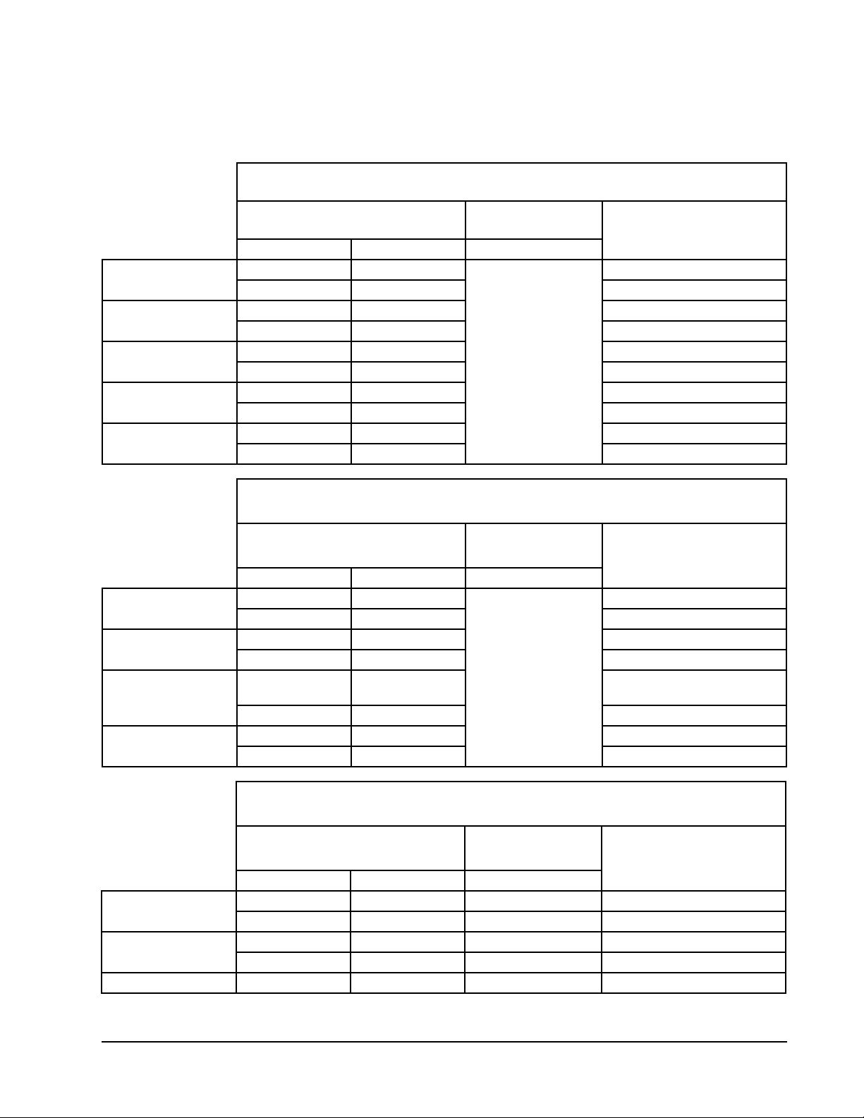
TABLE 2.2
Cooling Staging
1 Unit
Order Freecooling Available Freecooling Not Available
1 Unit 1 Freecooling Unit 1 Compressor Stage 1
2 Unit 1 Compressor Stage 1 Unit 1 Compressor Stage 2
3 Unit 1 Compressor Stage 2 --
2 Units
Order Freecooling Available Freecooling Not Available
1 Unit 1 Freecooling Unit 1 Compressor Stage 1
2 Unit 2 Freecooling Unit 1 Compressor Stage 2
3 Unit 1 Compressor Stage 1 Unit 2 Compressor Stage 1
4 Unit 1 Compressor Stage 2 Unit 2 Compressor Stage 2
5 Unit 2 Compressor Stage 1
6 Unit 2 Compressor Stage 2
--
3 Units
Order Freecooling Available Freecooling Not Available
1 Unit 1 Freecooling Unit 1 Compressor Stage 1
2 Unit 2 Freecooling Unit 1 Compressor Stage 2
3 Unit 3 Freecooling Unit 2 Compressor Stage 1
4 Unit 1 Compressor Stage 1 Unit 2 Compressor Stage 2
5 Unit 1 Compressor Stage 2 Unit 3 Compressor Stage 1
6 Unit 2 Compressor Stage 1 Unit 3 Compressor Stage 2
7 Unit 2 Compressor Stage 2
--8 Unit 3 Compressor Stage 1
9 Unit 3 Compressor Stage 2
4 Units
Order Freecooling Available Freecooling Not Available
1 Unit 1 Freecooling Unit 1 Compressor Stage 1
2 Unit 2 Freecooling Unit 1 Compressor Stage 2
3 Unit 3 Freecooling Unit 2 Compressor Stage 1
4 Unit 4 Freecooling Unit 2 Compressor Stage 2
5 Unit 1 Compressor Stage 1 Unit 3 Compressor Stage 1
6 Unit 1 Compressor Stage 2 Unit 3 Compressor Stage 2
7 Unit 2 Compressor Stage 1 Unit 4 Compressor Stage 1
8 Unit 2 Compressor Stage 2 Unit 4 Compressor Stage 2
9 Unit 3 Compressor Stage 1
10 Unit 3 Compressor Stage 2
11 Unit 4 Compressor Stage 1
12 Unit 4 Compressor Stage 2
--
Page 33 of 36

5. Press ENTER key to scroll to Time Based (see
Figure 2.7).
6. Press UP or DOWN key to change the value from
ON to OFF.
7. Press ENTER key to save the value and move
cursor to Num. of Days.
8. Press UP or DOWN keys to change the value.
9. Press ENTER key to save the value and move
cursor to Manual Rotate.
10. Press UP or DOWN key to change the value from
OFF to ON.
11. Press ENTER key to save.
FIGURE 2.7
Adjusting Unit Rotation Parameters
Heating
When the wall units are connected to the LV, the heat
strips are commanded off and on by the LV. This allows
the supervisory controller to match the required load
of the shelter using all of the available equipment
installed on the shelter.
To adjust the heating setpoint:
1. Press MENU key to go to the Main Menu screen.
2. Press UP or DOWN keys and ENTER key to enter
USER password 2000.
3. Press UP or DOWN keys to scroll to Sys Config;
press ENTER key.
4. Press UP or DOWN keys to scroll to Unit Setup
(A1); press ENTER key.
5. Press ENTER key to scroll to Heating (see Figure
2.6 on page 34).
6. Press UP or DOWN keys to adjust value.
7. Press ENTER key to save.
8. Press the ESCAPE key several times to return to
Main Menu screen.
The LV monitors the space temperature and compares
the value to the space heating setpoint. The system will
compare how far above or below the space temperature
is when compared to the heating setpoint. The LV will
also consider how long the shelter temperature has
been above or below the setpoint. Using these two
considerations, the controller will generate a heating
demand. The heating demand is a value between 0 and
100%. 0% represents no heating demand and 100%
representing full heating demand.
The system will consider all of the available heating
stages and distribute the number of stages across
the heating demand range. As the demand rises, the
system will stage on equipment every 2 minutes. As the
demand lowers, the system will stage off equipment
every 2 minutes.
The system will stage the equipment on in the order
shown in Table 2.3.
The system is also capable of rotating the order
in which the units are brought on. This is done to
distribute the equipment run time to each unit. This
prevents one unit from providing all of the heating
for the shelter and shortening the lifespan of the wall
unit. The system is set to switch the unit staging order
every 7 days from the factory. This timeframe can be
changed if desired by the end user. In addition to the
time-based auto rotation, the system can be manually
rotated on site for troubleshooting purposes.
To view the lead unit, turn the rotation on/off, change
the number of days between rotations or manually
rotate the units:
1. Press MENU key to go to the Main Menu screen.
2. Press UP or DOWN keys and ENTER key to enter
USER password 2000.
3. Press UP or DOWN keys to scroll to Sys Config;
press ENTER key.
4. Press UP or DOWN keys to scroll to Unit Rotation
(A2); press ENTER key.
5. Press ENTER key to scroll to Time Based (see
Figure 2.7).
6. Press UP or DOWN key to change the value from
ON to OFF.
7. Press ENTER key to save the value and move
cursor to Num. of Days.
8. Press UP or DOWN keys to change the value.
9. Press ENTER key to save the value and move
cursor to Manual Rotate.
10. Press UP or DOWN key to change the value from
OFF to ON.
11. Press ENTER key to save.
Humidity Control
The LV will monitor the indoor humidity of the space
and compare the value to the indoor humidity lower
and upper setpoints.
Page 34 of 36

TABLE 2.3
Heating Staging
1 Unit
Order Heat Method
1 Unit 1 Heat Strip
2 Units
Order Heat Method
1 Unit 1 Heat Strip
2 Unit 2 Heat Strip
3 Units
Order Heat Method
1 Unit 1 Heat Strip
2 Unit 2 Heat Strip
3 Unit 3 Heat Strip
4 Units
Order Freecooling Available
1 Unit 1 Heat Strip
2 Unit 2 Heat Strip
3 Unit 3 Heat Strip
4 Unit 4 Heat Strip
Humidification
When the humidity is below the lower setpoint of 20%
RH and a humidifier output is configured, the shelter
will begin to humidify using the relay output to control
a third party humidifier.
To change the number of humidifiers, type and
setpoint:
1. Press MENU key to go to the Main Menu screen.
2. Press UP or DOWN keys and ENTER key to enter
USER password 2000.
3. Press UP or DOWN keys to scroll to Sys Config;
press ENTER key.
4. Press UP or DOWN keys to scroll to Unit Setup
(A3); press ENTER key.
5. Press ENTER key to scroll to Humidifiers (see
Figure 2.8).
6. Press UP or DOWN keys to adjust value.
7. Press ENTER key to scroll to Humidifier Type.
8. Press UP or DOWN keys to adjust value.
9. Press ENTER key to scroll to Humidifier Setpoint
Humidity.
10. Press UP or DOWN keys to adjust value.
11. Press the ESCAPE key several times to return to
Main Menu screen.
FIGURE 2.8
Adjusting Setpoints
Dehumidification
The system will take several actions to limit the indoor
humidity level. At 70% RH, the economizer will be
disabled to prevent outdoor air from being used to cool
the shelter which may have a high moisture content.
This mode will remain active until the shelter humidity
level is below 60% RH. The system will switch from
high sensible to standard mode when the indoor
humidity is above 75% RH which will slow the blower
down to remove more moisture. This mode will remain
active until the shelter humidity level is below 65%.
If the shelter reaches 80% RH, the system will switch
the units into dehumidification mode. This mode will
cool the shelter down to the heating setpoint and
the compressor will turn off. Then the heat strip will
activate and heat it back up to the cooling setpoint,
then turn off. This will continue until the indoor
humidity level is below 70% RH.
Fan Control
The LV has the option to change the continuous blower
setting of the units connected to it. The options are All,
Lead and None. If the option is set to All, then all of
the units connected will run the blower continuously.
If the option is set to Lead, only the unit in the lead
position will run the blower continuously. If the option
is set to None, then none of the units will run the
blower continuously. When continuous blower doesn’t
apply to a unit, it will cycle the blower based on
heating or cooling calls.
Hour Counting
The LV will keep track of the heating and cooling
method run times for last hour. In addition to how long
an item was on, it will also track how many times a
method started.
Page 35 of 36

ADDITIONAL PROGRAMMING
LV1000 Menus/Screens
Main Menu
Press the MENU key from any screen to return to the
Main Menu. Press the UP or DOWN keys to scroll
through the available menus. When the desired menu
is highlighted, press the ENTER key to access that
menu. Press the ESCAPE key or MENU key to return to
the Status screen from the Main Menu.
Status Screen
The Status screen is the default start-up screen and
also the return screen after 5 minutes of no activity.
The screen can be accessed any time by pressing the
ESCAPE key repeatedly. The LV1000 Status screen
displays the current date, time, unit displayed, zone
and unit status.
Quick Menu
The Quick Menu is available on the Status screen. Use
UP or DOWN keys while on the Status screen to scroll
between the three Quick Menu options; press ENTER
key.
Data Log
The data log displays the record number, time of alarm
event, date of alarm event, description of alarm event
and whether the entry is the beginning or end of event.
The data log will have as many screens as events
occurred.
Info
Info displays wall unit status for each wall-mount unit
connected to controller, last hour tracking (shelter), last
hour tracking (for each wall-mount unit connected, last
hour averages (zone temperatures, OA temperature and
OA humidity) and additional LV1000 information.
Setpoints
Setpoints allows setting and enabling of comfort mode.
Calibrating Sensors
1. Press MENU key to go to the Main Menu screen.
2. Use UP or DOWN keys and ENTER key to enter
USER password 2000.
3. Press UP or DOWN keys to scroll to I/O Config;
press ENTER key.
4. Press UP or DOWN keys to scroll to sensor to be
adjusted.
5. Press ENTER key to scroll to Offset.
6. Press UP or DOWN keys to add or subtract to the
sensor offset value.
7. Press ENTER key to save.
Changing to Celsius
1. Press MENU key to go to the Main Menu screen.
2. Use UP or DOWN keys and ENTER key to enter
USER password 2000.
3. Press UP or DOWN keys to scroll to Sys Config;
press ENTER key.
4. Press UP or DOWN keys to scroll to Unit Setup
(A1).
5. Press ENTER key to scroll to UOM.
6. Press UP and DOWN keys to change value to SI.
Page 36 of 36
 Loading...