

Page 1

SERVICE AND INSTALLATION
INSTRUCTIONS
WITH REPLACEMENT PARTS LIST
LC6000-200 CONTROLLER
Part of the Bard Cooling System
NOTE: LC6000-200 controller is required for operation when
multiple MULTI-TEC
MEGA-TECTM wall-mount units are used.
Additional information regarding the installation and setup
of the LC6000-200 controller and software is included in
the system installation instructions located inside the wallmount unit control panel.
Bard Manufacturing Company, Inc.
Bryan, Ohio 43506
www.bardhvac.com
®, FUSION-TEC® WR Series and/or
Manual : 2100-669F
Supersedes: 2100-669E
Date: 3-18-19
Page 1 of 37
Page 2

CONTENTS
LC6000 Controller Installation ................................... 5
LC6000 Controller .................................................. 6
Mounting the LC6000 Controller ....................... 6
Supply Wiring .................................................. 7
Installing Remote Indoor Temperature/Humidity
Sensor(s) ......................................................... 8
Emergency Off, Emergency Vent and Generator
Run Connections ............................................ 11
Communication Wiring .................................... 12
Installing Outdoor Temperature/Humidity Sensor ..
10
Alarms .................................................................15
Alarm Adjustment ...............................................15
Acknowledging/Clearing Alarms ......................15
Low Temperature Alarm .................................15
High Temperature Alarm ................................15
High Temperature 2 Alarm .............................16
Emergency Off Alarm .................................... 16
Generator Alarm ...........................................17
Emergency Vent Alarm ..................................18
Zone Unit Alarm ........................................... 18
Humidity Alarm ............................................19
Control Operation .............................................21
Temperature Control ............................................21
Indoor Temperature Averaging ........................21
Comfort Mode ..............................................21
Staging ............................................................21
FIFO (First In First Out) .................................21
LIFO (Last In First Out) ................................. 21
Demand Staging ...........................................21
Staging Delay ...............................................22
Maximum Number of Units Running...............22
Rotation ......................................................22
Demand .......................................................23
Humidity Control .................................................23
Dehumidification ..........................................23
Humidification .............................................24
Enabling Humidifier ...............................24
Continuous Blower ..............................................25
Continuous Blower Custom Configuration ........ 25
Additional Information ....................................26
LC6000 Menus/Screens ......................................26
Main Menu ..................................................26
Status Screen ..............................................26
Quick Menu .................................................26
Alarm Log .............................................26
Info ......................................................26
Setpoints ..............................................26
Menu Screens and Password Levels ................27
Additional Programming ......................................27
Changing to Celsius ......................................27
Configuring Number of Units .........................27
Calibrating Sensors .......................................28
Clearing Alarm Logs ...................................... 28
Configuring Free Cooling ...............................28
Enabling High Sensible Operation .................. 28
Troubleshooting ................................................30
8403-079 Remote Indoor Temp/Humidity Sensor ..30
8301-090 Outdoor Temp/Humidity Sensor ............33
LC6000 Replacement Parts List ......................37
FIGURES AND TABLES
Figure 1
Figure 2 LC6000 Fused Power Supply Terminals ....6
Figure 3 LC6000 Controller Supply Wiring .............7
Figure 4 Controller Grounding Posts ......................7
Figure 5 Remote Indoor Temperature/Humidity
Sensor Installation .................................. 8
Figure 6
Figure 7 Remote Outdoor Temperature/Humidity
Sensor Installation ................................ 10
Figure 8 Emergency Off, Emergency Vent and
Generator Run Connections ...................11
Figure 9 Communication Wiring: Termination at
the Controller ....................................... 12
Figure 10 Communication Wiring (Daisy Chain) ......13
Figure 11 Communication Wiring (Alt. Method) ......13
Figure 12 Placement of Communication Filters ......14
Figure 13 Adjust Alarm Setpoints .........................15
Figure 14 Adjust Alarm Remote Notification Relay
Output Direction ................................... 15
Figure 15 Adjust Emergency Off, Emergency Vent
or Generator Alarm Input Direction .........16
Figure 16 Adjust Alarm Remote Notification Relay
Output Direction ................................... 17
Figure 17 Adjust Units Running When Generator
Is Active ..............................................17
Figure 18 Adjust Zone Alarm Configuration ............19
Figure 19 Adjust Humidity Alarm Setpoints ...........20
Figure 20 Change Indoor Temperature Averaging
Type ....................................................21
Figure 21 Adjust Staging Settings .........................22
Figure 22 Staging Maximum Number of Units
Running ..............................................22
Figure 23 Rotation ..............................................23
Figure 24 Humidity Control Setpoints ....................24
Figure 25 Dehumidification Types .........................24
Figure 26 Enabling Humidifier ..............................24
Figure 27 Continuous Blower Status ......................25
Figure 28
Figure 29 MULTI-TEC Unit Info Screen .................26
Figure 30
Figure 31 MEGA-TEC Unit Info Screen ..................26
Figure 32 Changing to Celsius ..............................27
Figure 33 Clearing LC6000 Alarm Logs .................28
Figure 34 Configuring Free Cooling .......................28
Figure 35 Enabling High Sensible Operation ..........29
Figure 36 8403-079 Sensor .................................30
Figure 37 8301-090 Sensor .................................33
Figure 38 LC6000-200 Wiring Diagram .................36
Table 1 LC6000 Passwords (Defaults) ................27
Table 2 LC6000 Status Messages ......................27
Table 3 8403-079 Sensor: Temp/Resistance.......31
Table 4 8403-079 Sensor: Voltage/Humidity ......32
Table 5 8301-090 Sensor: Temp/Resistance.......33
Table 6 LC6000-200 Terminal Block Index ........34
Table 7
Typical LC6000-200 Component Location ..
Additional Remote Sensor Installation .......
Continuous Blower Custom Configuration ..
FUSION-TEC WR Series Unit Info Screen ..
LC6000-200 to Sensor Connection Index ..
5
9
25
26
35
Manual 2100-669F
Page 2 of 37
Page 3
GENERAL INFORMATION
Cooling System
This Bard cooling system is composed of MULTI-TEC, FUSION-TEC WR Series and/or MEGA-TEC wall-mounted
air conditioners matched with an LC6000 controller or Bard th-Tune stand-alone controller (th-Tune can only be
used with MULTI-TEC units). If only one wall-mounted air conditioner is being used, it can be matched with either
the LC6000 or a th-Tune stand-alone controller (if applicable). If more than one wall-mount unit is installed, the
LC6000 controller must be matched with the air conditioning units. The wall-mount units are specifically engineered
for equipment cooling applications.
NOTE: The LC6000 controller and MULTI-TEC, FUSION-TEC WR Series and MEGA-TEC wall-mount units are
designed specifically to work together. The controller cannot run other brands of systems, nor can other
controllers run the MULTI-TEC, FUSION-TEC WR Series or MEGA-TEC wall-mount units. They are a
complete system, and must be used together.
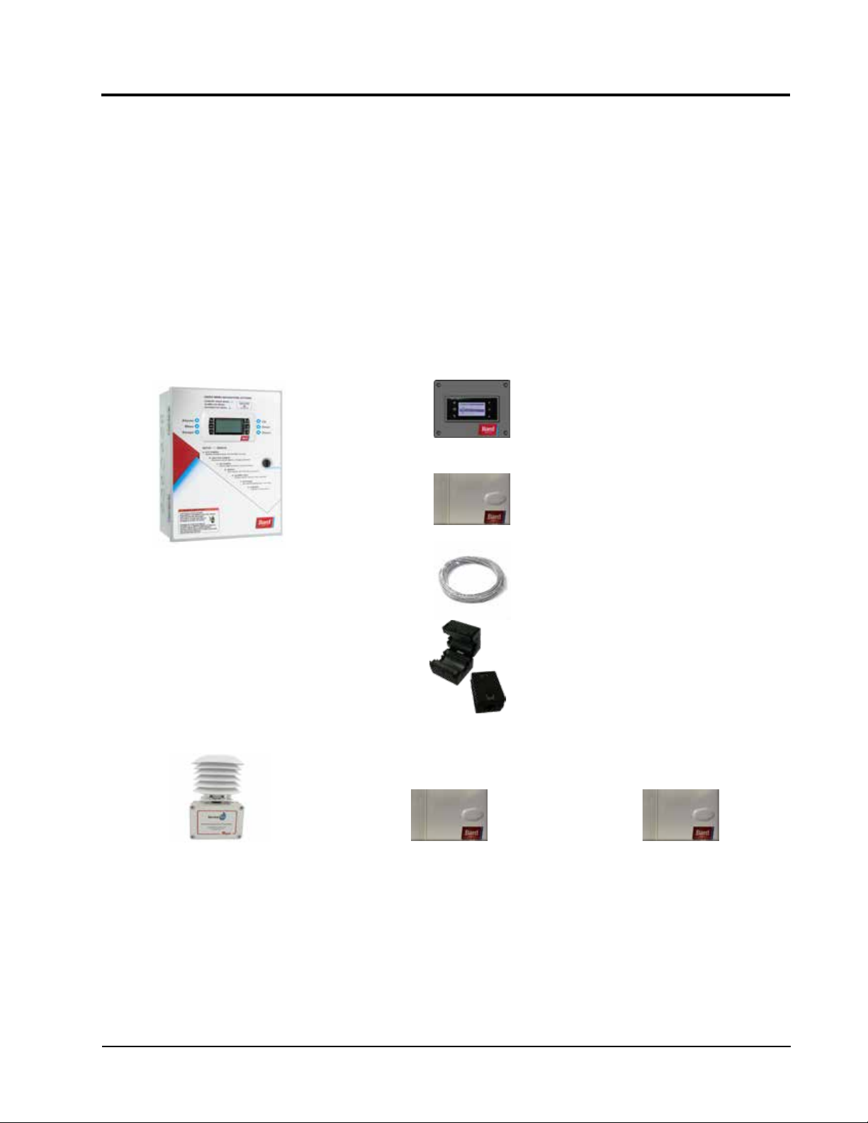
LC6000-200 Series Controller and Accessories Included with Controller
(1) TEC-EYETM Hand-Held Diagnostic Tool
Bard P/N 8301-059
(1) LC6000 Programmable Logic
Controller
Outside Air
Temperature/Humidity Sensor
Bard P/N 8301-090
+
Optional Sensors:
Remote
Temperature/Humidity Sensor
Bard P/N 8403-079
(1) Remote Temperature/Humidity Sensor1
Bard P/N 8403-079
(1) 35' 5-Wire 18 Gauge Shielded Cable
(2) Communication EMI Filters
Bard P/N 8301-055
1
Temperature Only Sensor
Remote
Bard P/N 8301-058
1
One remote temperature/humidity sensor is included with the LC6000 controller. If the site in which the LC6000
controller will be used has more than one zone (maximum three zones per LC6000), additional remote temperature/
humidity sensors (one sensor per zone) will need to be purchased and installed in the additional zones. One
additional temperature-only sensor (Bard P/N 8301-058) may also be used in Zone 1 but will also need to be
purchased separately. Additional temperature/humidity sensors require field-supplied 5-wire 18 gauge shielded
cable. Temperature-only sensors require field-supplied 2-wire 18 gauge shielded cable.
Manual 2100-669F
Page 3 of 37
Page 4
The equipment covered in this manual is to be installed
by factory trained and certified, experienced service and
installation technicians.
These instructions should be carefully read before
beginning the installation. Note particularly any tags
and/or labels attached to the equipment.
While these instructions are intended as a general
recommended guide, they do not supersede any national
and/or local codes in any way. Authorities having
jurisdiction should be consulted before the installation is
made. See Additional Publications for information
on codes and standards.
Shipping Damage
Upon receipt of equipment, the cartons should be
checked for external signs of shipping damage. If
damage is found, the receiving party must contact
the last carrier immediately, preferably in writing,
requesting inspection by the carrier’s agent.
Additional Publications
These publications can help when installing the air
conditioner. They can usually be found at the local
library or purchased directly from the publisher. Be
sure to consult the current edition of each standard.
ANSI Z535.5 Definitions:
DANGER: Indicate[s] a hazardous situation which, if
not avoided, will result in death or serious injury. The
signal word “DANGER” is to be limited to the most
extreme situations. DANGER [signs] should not be used
for property damage hazards unless personal injury risk
appropriate to these levels is also involved.
WARNING: Indicate[s] a hazardous situation which,
if not avoided, could result in death or serious injury.
WARNING [signs] should not be used for property
damage hazards unless personal injury risk appropriate
to this level is also involved.
CAUTION: Indicate[s] a hazardous situation which, if
not avoided, could result in minor or moderate injury.
CAUTION [signs] without a safety alert symbol may be
used to alert against unsafe practices that can result in
property damage only.
NOTICE: [this header is] preferred to address practices
not related to personal injury. The safety alert symbol
shall not be used with this signal word. As an
alternative to “NOTICE” the word “CAUTION” without
the safety alert symbol may be used to indicate a
message not related to personal injury.
National Electrical Code ...................... ANSI/NFPA 70
Standard for the Installation of Air Conditioning
and Ventilating Systems ...................ANSI/NFPA 90A
Standard for Warm Air Heating
and Air Conditioning Systems ............ANSI/NFPA 90B
Load Calculation for Residential Winter
and Summer Air Conditioning ............. ACCA Manual J
Duct Design for Residential Winter and Summer
Air Conditioning and Equipment Selection
....................................................... ACCA Manual D
For more information, contact these publishers:
Air Conditioning Contractors of America (ACCA)
1712 New Hampshire Ave. N.W.
Washington, DC 20009
Telephone: (202) 483-9370 Fax: (202) 234-4721
American National Standards Institute (ANSI)
11 West Street, 13th Floor
New York, NY 10036
Telephone: (212) 642-4900 Fax: (212) 302-1286
American Society of Heating, Refrigeration and Air
Conditioning Engineers, Inc. (ASHRAE)
1791 Tullie Circle, N.E.
Atlanta, GA 30329-2305
Telephone: (404) 636-8400 Fax: (404) 321-5478
National Fire Protection Association (NFPA)
Batterymarch Park
P. O. Box 9101
Quincy, MA 02269-9901
Telephone: (800) 344-3555 Fax: (617) 984-7057
NOTICE
It is important to check the software version
during installation to ensure that the latest
version has been installed. Current software
versions, change log and installation
instructions are available on the Bard website at
http://www.bardhvac.com/software-download/
Manual 2100-669F
Page 4 of 37
Page 5
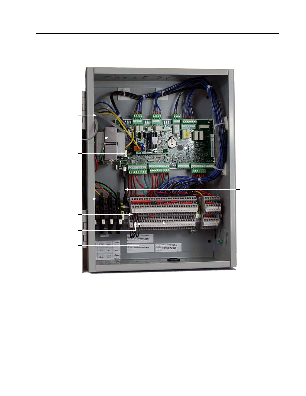
RJ11 Cable
to Display
Transformer
LC6000 CONTROLLER INSTALLATION
FIGURE 1
Typical LC6000-200 Component Location
Ethernet Cable
Connection
Four Fused
Power Supply
Terminals
Emergency Off
Alarm Jumper
Emergency Vent
Alarm Jumper
Generator Run
Alarm Jumper
Control Board
USB Male A
to Micro Male
B Cable
Terminal Block
Manual 2100-669F
Page 5 of 37
Page 6
!
WARNING
Electrical shock hazard.
Disconnect VAC power supplies before
servicing.
Failure to do so could result in electric shock
or death.
IMPORTANT: When working with circuit board
components,
an anti-static wrist strap to prevent static
electricity shorts to electronic controls.
Bard recommends the use of
LC6000 Controller
The LC6000 controller is part of this air conditioning
system. It is used to control up to 14 wall-mount air
conditioners from one controller. The microprocessor
control provides an easy-to-read interface with
large LCD graphical display. It provides control for
redundancy for the structure and equal wear on all
units.
Conduit is recommended for all wiring. Route
communication wiring and power supply wiring in their
own separate conduits.
The LC6000 controller is not weatherproof and is
intended for use in a weathertight structure.
IMPORTANT: When connecting this product from a
remote location, ensure that the network
connection is secure and reliable.
Mounting the LC6000 Controller
The dimensions of the LC controller are 16" x 12" x 6".
Because the LC6000 controller utilizes a remote
temperature sensor as opposed to one located in the
controller box, the controller itself can be installed in
any indoor location that is suitable, preferably at eye
level. Four (4) mounting holes are provided for mounting
to the wall and holes for conduit connections are provided
in the base, sides and top of the controller.
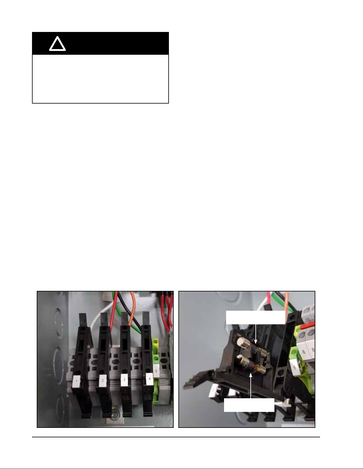
The LC6000 controller includes four fused power
supply terminals in the terminal block. Before
connecting wires to the terminal block, confirm that the
fuse in each of the four fuse holders is in the proper
position (active) as shown in Figure 2.
Manual 2100-669F
Page 6 of 37
FIGURE 2
LC6000 Fused Power Supply Terminals
Fuse in Active Position
Shipping Position
Page 7
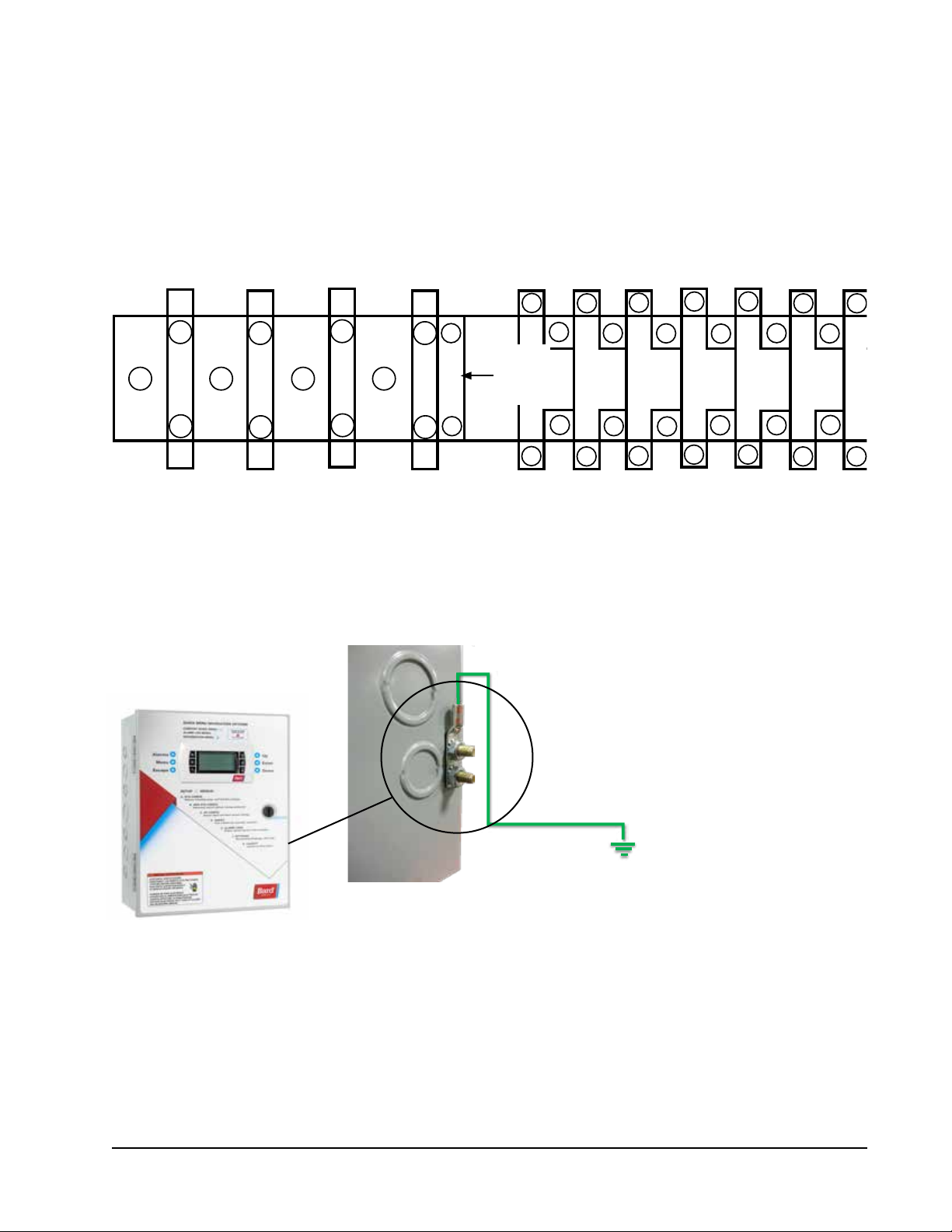
Supply Wiring
19
21
25
23
18
20
22 24
The LC6000 controller is powered by 120, 208 or 240 volts from the shelter. Field-supplied supply wiring should
be minimum 16 gauge, maximum 14 gauge (see Figure 3). A reliable earth ground must be connected in addition
to any grounding from conduit. Grounding bolts and nuts are included with the controller for this purpose; a 2 hole
grounding lug must be field supplied. Install as shown in Figure 4. Failing to ground the controller box properly could
result in damage to the equipment.
FIGURE 3
LC6000 Controller Supply Wiring
Power
1
2
3
4
5
Input
6
Ground
9
8 10 12
7
11 13
14
15
16
17
120
VAC
Input
(L1)
208V
VAC
Input
(L1)
240V
VAC
Input
(L1)
Power
Input
Common
(L2 or N)
FIGURE 4
Controller Grounding Posts
A reliable earth ground must be connected in
addition to any grounding from conduit. Attach
earth ground to side of controller box using bolts
and nuts supplied with controller and fieldsupplied 2 hole grounding lug. Failing to ground
the controller box properly could result in damage
to the equipment.
Manual 2100-669F
Page 7 of 37
Page 8
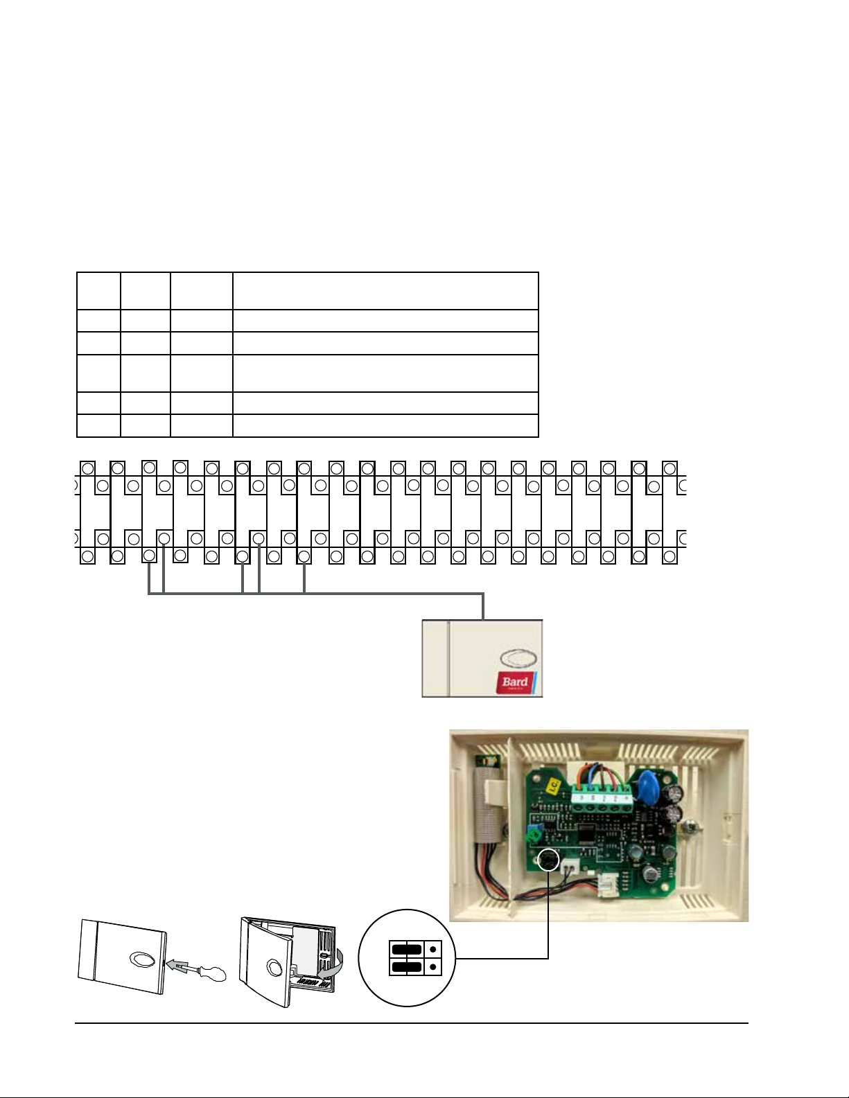
Installing Remote Indoor Temperature/Humidity Sensor(s)
47 51
49 53
55
59
57
60
48
50 52
54
56
58
One remote indoor temperature/humidity sensor and 35' of 18 gauge 5-conductor shielded cable is included with the
controller. This sensor must be installed for proper operation. Mount the temperature/humidity sensor in a location
least likely to be affected by open doors, rack-mounted fans, radiant heat sources, etc. Locating the sensor between
both return grilles is often the best location, but every installation is unique. Location height should be approximately
60" above the floor. The sensor should be installed on a 2" x 4" junction box to allow for control wire conduit. Use
shielded cable to connect to controller.
FIGURE 5
Remote Indoor Temperature/Humidity Sensor Installation
1. Connect wires from the 18 gauge shielded cable to terminals #12, #13, #18, #19 and #22.
TB#
Wire
Mark
Sensor Description
18 B6 NTC OUT Indoor Remote Sensor (Zone 1)
19 GND NTC OUT Ground
12 B2 OUT H Remote Indoor Humidity Sensor: 0-1 VDC (Zone 1)
13 GND M (GO) Ground
22 +VDC + (G) Power for B2
212523
11 13
9
8 10 12
14
16 18
15
17
19
20
22 24
26
27
28
29
30 32 34 36
313533
37
40
39 4341 45
38
42 44
46
2. Connect the other end of the shielded cable to the sensor
terminals. Be sure wires are connected to proper terminals
as shown in table above.
Sensor jumpers need to be positioned for 0-1 V. With sensor
oriented as shown in image to right, move both jumpers
to left position (DP1 and DP2 set to OFF). This applies
to all temperature/humidity sensors connected to the LC
controller.
Sensor is best mounted on a junction box, and it is
recommended that the cable be in conduit.
Jumper
DP1
DP2
Manual 2100-669F
Page 8 of 37
Page 9
For proper operation, the remote indoor temperature/humidity sensor (and any additional sensors) must be
configured properly with the controller as shown in Step 2 on page 8. An additional remote indoor temperature-
only sensor can be purchased and installed in Zone 1. If the site in which the LC6000 controller will be used has
more than one zone (maximum three zones per LC6000), additional remote temperature/humidity sensors (one per
zone) will need to be purchased and installed in the additional zones. All installed sensors must be enabled in the
controller menu (see Configure Sensors in system installation instructions included with the wall-mount unit).
FIGURE 6
Additional Remote Temperature and Temperature/Humidity Sensor Installation
One additional temperature sensor can be added to Zone 1 and additional temperature/humidity sensors may be
added to Zones 2 and 3 (one per zone). Be sure the sensors are connected to the proper terminals on the terminal
block and sensor as listed below.
Zone 1:
Optional Remote
Temperature Sensor
Terminals 20 & 21*
Zone 2:
Optional Remote
Temperature/Humidity Sensor
Terminals 26, 27, 14, 15 & 23
IMPORTANT: Note jumper
position in Figure 14
Zone 3:
Optional Remote
Temperature/Humidity Sensor
Terminals 28, 29, 16, 17 & 24
IMPORTANT: Note jumper
position in Figure 14
TB#
20 B7 Indoor Remote Sensor (Zone 1 – optional)
21 GND Ground
* The two wire connections for the optional remote temperature sensor
are not polarity sensitive.
TB#
26 B8 NTC OUT Indoor Remote Sensor (Zone 2)
27 GND NTC OUT Ground
14 B3 OUT H Remote Indoor Humidity Sensor: 0-1 VDC (Zone 2)
15 GND M (GO) Ground
23 +VDC + (G) Power for B3
TB#
28 B9 NTC OUT Indoor Remote Sensor (Zone 3)
29 GND NTC OUT Ground
16 B4 OUT H Remote Indoor Humidity Sensor: 0-1 VDC (Zone 3)
17 GND M (GO) Ground
24 +VDC + (G) Power for B4
Wire
Mark
Wire
Mark
Wire
Mark
Description
Sensor Description
Sensor Description
Zones 2 and 3 can also use temperature-only sensors in place of the temperature/humidity sensors. Zone 2 will connect
to TB# 26 and 27. Zone 3 will connect to TB# 28 and 29. The wire connections for the temperature-only sensors are not
polarity sensitive.
Manual 2100-669F
Page 9 of 37
Page 10
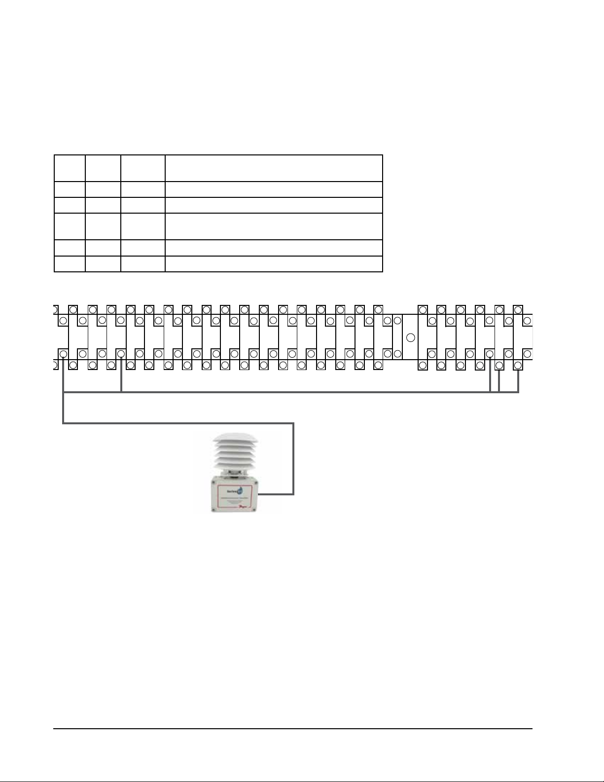
Installing Optional Outdoor Temperature/Humidity Sensor
One optional outdoor temperature/humidity sensor (8301-090) can be installed. Follow the manufacturer's mounting
instructions. Use 18 gauge 5-conductor shielded cable to connect to controller.
FIGURE 7
Remote Outdoor Temperature/Humidity Sensor Installation
1. Connect wires from the 18 gauge shielded cable to terminals #65, #66, #67, #70 and #71.
TB#
Wire
Mark
Sensor Description
70 B12 4 Remote Outdoor Temperature Sensor
71 ND 5 Ground
67 B11 1 Remote Outdoor Humidity Sensor: 0-10 VDC
66 GND 3 Ground
65 +VDC 2 +VDC
28
25
26
27
29
30 32 34 36
313533
37
40
38
39 4341 45
42 44
47 51
46 48
49 53
50 52
54
55
56
57
58
59
60
62
61 65
64 66
63
68
67
70
69
72
71
2. Connect the other end of the shielded cable to the sensor terminals. Be sure wires are connected to proper terminals
as shown in table above.
Manual 2100-669F
Page 10 of 37
Page 11

Emergency Off, Emergency Ventilation and Generator Run Connections
27
29
31
33
26
28
30 32 34 36
The LC6000-200 controller is shipped with emergency off, emergency ventilation and generator run contacts. There
are factory-installed jumpers across terminals #6 and #7 (emergency off), #8 and #9 (emergency ventilation) and
#10 and #11 (generator run). Remove the factory-installed jumpers before making the connections.
FIGURE 8
LC6000-200 Series Connection for Emergency Off, Emergency Ventilation and Generator Run (If Applicable)
3
4
5
7
6
9
8 10 12
11 13
14
Generator Run*
Emergency Ventilation*
Emergency Off*
* Normally closed (NC) contacts required.
By default:
Closed = No Alarm
Open = Alarm
17
16 18
15
19
20
21
23
22 24
25
Manual 2100-669F
Page 11 of 37
Page 12
- +
G
63
61 65
67
62
64 66
68
Communication Wiring
The steps outlined on the following pages show how to connect the communication wiring to the LC controller.
Communication wire connections to the wall-mount unit vary with the different units. See the system installation
instructions included with the wall-mount unit for information on connecting the communication wiring to the wallmount unit(s).
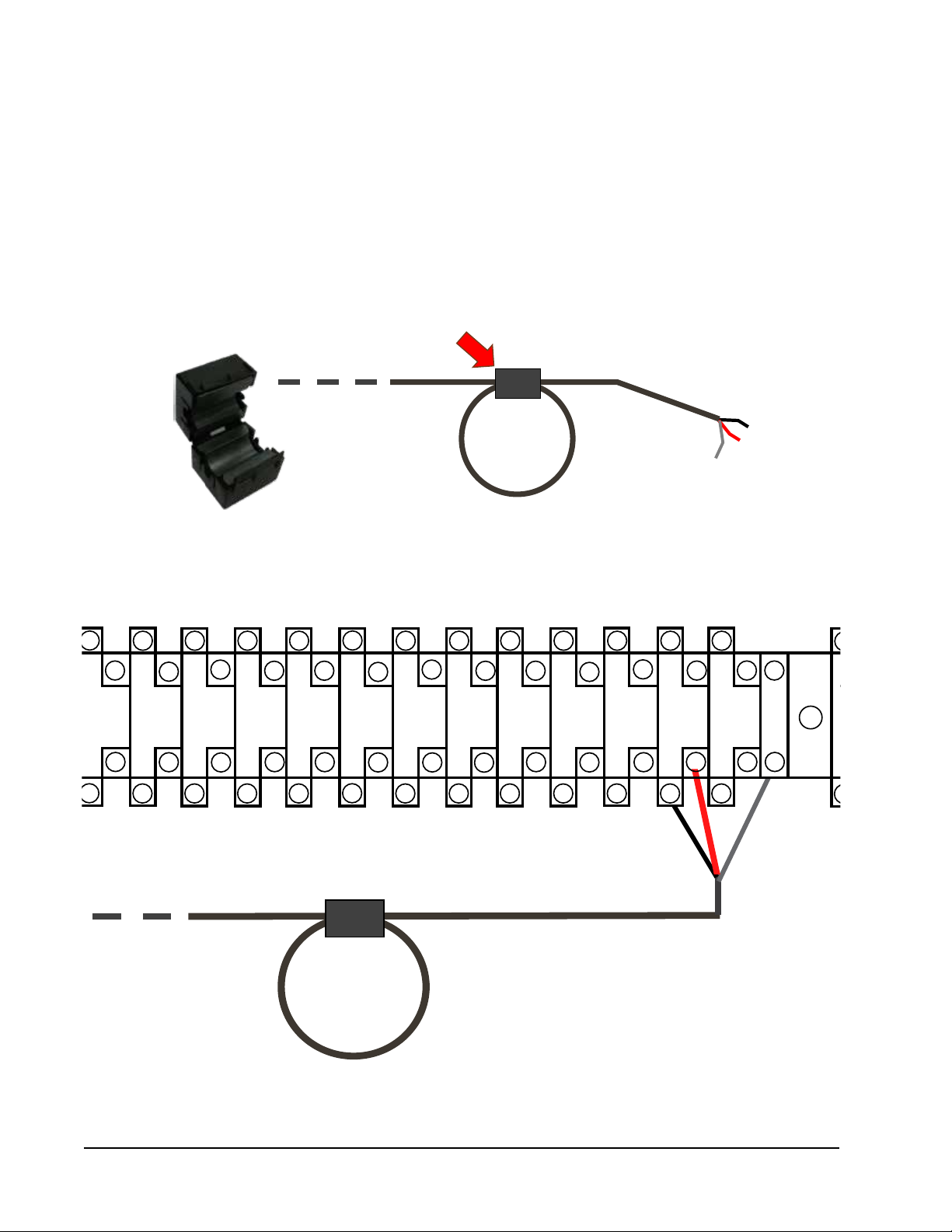
FIGURE 9
Communication Wiring: Termination at the Controller
1. Using the field-provided shielded cable, make a small service loop after entering the controller and attach the provided
EMI filter at the intersection of the loop.
2. Connect one wire to terminal #56 (negative), the other wire to terminal #57 (positive) and the drain wire to ground
terminal #60.
36
37
38
40
39 4341 45
42 44
47 51
46 48
49 53
50 52
54
55
56
57
58
59
60
35
+
–
To Wall-Mount Unit 1
Manual 2100-669F
Page 12 of 37
Page 13

Connect the communication wiring from the controller to the wall-mount units in the manner shown in Figures 10,
11 or 12. The daisy chain does not need to follow the addressing order. The communication wire should be 2-wire,
18 gauge shielded cable with drain. Any color can be used. Be sure to match "+" and "-" symbols on controller
terminal blocks to prewired unit control terminal block. Attach communication wire filters as shown in Figures 10,
11 or 12. Do not run communication wiring in same conduit as supply wiring.
Route communication wiring and
power supply wiring in their own separate conduits.
The wall-mount units may not look the same as those depicted in the figures but these directions apply to all
units connected to the LC6000-200 controller.
FIGURE 10
Communication Wiring (Daisy Chain Method)
Filter
Filter
Wall-Mount Unit Wall-Mount Unit
LC6000 Controller
In addition to the "daisy chain" method of connecting the communication wiring shown in Figure 10, the wall-mount
units can also be connected in the manner shown in Figure 11. If connecting wall-units this way, be sure to place
the communication wire filters in the positions shown in Figure 11. See Figure 12 on page 14 for more information
on the correct placement of the communication wire filters depending on the wiring method used.
FIGURE 11
Communication Wiring (Alternate Method)
Wall-Mount Unit
LC
Controller
Filter
Filter
Wall-Mount Unit
Manual 2100-669F
Page 13 of 37
Page 14

FIGURE 12
Placement of Communication Wire Filters (Daisy Chain and Alternate Methods)
Place filter here
Place filter here
(end unit)
LC6000
Daisy Chain Wiring
Unit 1 Unit 2 Unit 3 Unit 4 Unit 5
Alternate Wiring
LC6000*
Place filter here
(end unit)
... up to 14 units
Place filter here
(end unit)
Unit 1 Unit 2
Unit 3 Unit 4 Unit 5
... up to 14 units
* LC6000 can be in any position other than start and end
NOTE: Line filters can be on either the unit or controller, whichever device is on the end of the chain. No matter
how many units there are, the two end devices will only have ONE communication cable, whereas the
center devices will all have TWO (as shown above). Maximum two wires in each terminal. Filters go inside
the unit or controller; shown out of unit above for identification only.
Manual 2100-669F
Page 14 of 37
Page 15

ALARMS
NOTE: Screenshots shown in this manual reflect
default settings (when applicable).
Alarm Adjustment
Acknowledging/Clearing Alarms
Alarm conditions activate a red LED indicator that
backlights the ALARM function key. As an option, an
alarm condition may also be enunciated by an audible
alarm signal. An alarm is acknowledged by pressing the
ALARM key. This calls up alarm display screen(s) that
provide a text message detailing the alarm condition(s).
After an alarm condition is corrected, the alarm can be
cleared by pressing the ALARM key for 3 seconds.
Low Temperature Alarm
If the lowest temperature sensor value in a zone is
below the low temperature setpoint, an alarm will be
generated for that zone. Additionally, a relay output will
be actuated from the LC controller to provide remote
notification of the event.
NOTE: This alarm is per zone. If each zone is meant to
operate within the same alarm parameters, each
zone will need to be set accordingly.
To adjust the low temperature alarm setpoint:
1. Press MENU key to go to the Main Menu screen.
2. Use UP or DOWN keys and ENTER key to enter
USER password 2000.
3. Press UP or DOWN keys to scroll to Sys Config;
press ENTER key.
4. Press UP or DOWN keys to scroll to Zone 1, Zone 2
or Zone 3; press ENTER key.
5. Press UP or DOWN keys to scroll to Alarm
Setpoints A2-9 (Zone 1), Alarm Setpoints A3-9
(Zone 2) or Alarm Setpoints A4-9 (Zone 3).
6. Press ENTER key to scroll to the variable labeled
Low Temp (see Figure 13).
7. Press UP or DOWN keys to adjust setpoint.
FIGURE 13
Adjust Alarm Setpoints
To change the direction of the remote notification relay
output:
1. Press MENU key to go to the Main Menu screen.
2. Use UP or DOWN keys and ENTER key to enter
USER password 2000.
3. Press UP or DOWN keys to scroll to IO Config;
press ENTER key.
4. Press UP or DOWN keys to scroll to Digital Out
Config C3.
Press ENTER key to scroll to the variable in the table
5.
that intersects LoTemp and Dir (see Figure 14).
6. Press UP or DOWN key to change direction.
The low temperature notification relay has dry contacts.
The Dir, direction, is the position of the relay without
a low temperature event. NO is normally open; NC is
normally closed.
When the Val (value) is OFF, the relay is not in an alarm
condition. When the Val (value) is ON, the relay is in
an alarm condition. The relay connections for the low
indoor temperature alarm are on the LC6000 terminal
block; see Table 6 on page 34 for terminal block index.
FIGURE 14
Adjust Alarm Remote Notification
Relay Output Direction
High Temperature Alarm
If the highest temperature sensor value in a zone is
above the high temperature setpoint, an alarm will be
generated for that zone. When this alarm is present,
emergency cooling in this zone will become active.
There are two high temperature alarm setpoints. This
is the first and there is no remote notification for this
alarm.
NOTE: This alarm is per zone. If each zone is meant to
operate within the same alarm parameters, each
zone will need to be set accordingly.
To adjust the high temperature alarm setpoint:
1. Press MENU key to go to the Main Menu screen.
Manual 2100-669F
Page 15 of 37
Page 16

2. Use UP or DOWN keys and ENTER key to enter
USER password 2000.
3. Press UP or DOWN keys to scroll to Sys Config;
press ENTER key.
4. Press UP or DOWN keys to scroll to Zone 1, Zone 2
or Zone 3; press ENTER key.
5. Press UP or DOWN keys to scroll to Alarm
Setpoints A2-8 (Zone 1), Alarm Setpoints A3-8
(Zone 2) or Alarm Setpoints A4-8 (Zone 3).
6. Press ENTER key to scroll to the variable labeled
High Temp (see Figure 13).
7. Press UP or DOWN keys to adjust setpoint.
High Temperature 2 Alarm
If the highest temperature sensor value in a zone is
above the high temperature 2 setpoint, an alarm will
be generated for that zone. When this alarm is present,
the units will emergency cool in this zone. Additionally,
a relay output will be actuated from the LC to provide
remote notification of the event.
NOTE: This alarm is per zone. If each zone is meant to
operate within the same alarm parameters, each
zone will need to be set accordingly.
To adjust the high temperature 2 alarm setpoint:
1. Press MENU key to go to the Main Menu screen.
2. Use UP or DOWN keys and ENTER key to enter
USER password 2000.
3. Press UP or DOWN keys to scroll to Sys Config;
press ENTER key.
4. Press UP or DOWN keys to scroll to Zone 1, Zone 2
or Zone 3; press ENTER key.
5. Press UP or DOWN keys to scroll to Alarm
Setpoints A2-9 (Zone 1), Alarm Setpoints A3-9
(Zone 2) or Alarm Setpoints A4-9 (Zone 3).
6. Press ENTER key to scroll to the variable labeled
High Temp 2 (see Figure 13).
7. Press UP or DOWN keys to adjust setpoint.
To change the direction of the remote notification relay
output:
1. Press MENU key to go to the Main Menu screen.
2. Use UP or DOWN keys and ENTER key to enter
USER password 2000.
3. Press UP or DOWN keys to scroll to IO Config;
press ENTER key.
4. Press UP or DOWN keys to scroll to Digital Out
Config C3.
Press ENTER key to scroll to the variable in the
5.
table that intersects HiTemp and Dir (see Figure
14).
6. Press UP or DOWN key to change direction.
When the Val (value) is OFF, the relay is not in an
alarm condition. When the Val (value) is ON, the relay
is in an alarm condition. The relay connections for the
high indoor temperature 2 alarm are on the LC6000
terminal block; see Table 6 on page 34 for terminal
block index.
Emergency Off Alarm
If the LC gets an input from a smoke detector or similar
device, an alarm will be generated and all units will be
shut down. Additionally, a relay output will be actuated
from the LC to provide remote notification of the event.
The emergency off input can be configured to accept
either normally open or normally closed inputs. The
controller is defaulted to normally open and a jumper is
placed across the terminals of the input (#6 and #7).
When this jumper is removed, the alarm will become
active.
To change the direction of the emergency off input:
1. Press MENU key to go to the Main Menu screen.
2. Use UP or DOWN keys and ENTER key to enter
USER password 2000.
3. Press UP or DOWN keys to scroll to IO Config;
press ENTER key.
4. Press UP or DOWN keys to scroll to Digital In
Config C1.
Press ENTER key to scroll to the variable in the
5.
table that intersects EM Off and Dir (see Figure 15).
6. Press UP or DOWN key to change direction.
Emergency Off (EM Off) Dir (direction) is the position
of the smoke detector contacts in the event of smoke.
NO is normally open; NC is normally closed.
EM Off En (enable) allows the LC controller to monitor
the smoke detector when set to ON. When set to OFF,
the LC controller ignores the smoke detector.
EM Off Val (value) of ON indicates a smoke event. A
Val (value) of OFF indicates no smoke event.
Smoke detector connections (emergency off input) are
on the LC6000 terminal block; see Table 6 on page 34
for terminal block index.
FIGURE 15
Adjust Emergency Off, Emergency Vent or
Generator Alarm Input Direction
Manual 2100-669F
Page 16 of 37
Page 17

To change the direction of the remote notification relay
output:
1. Press MENU key to go to the Main Menu screen.
2. Use UP or DOWN keys and ENTER key to enter
USER password 2000.
3. Press UP or DOWN keys to scroll to IO Config;
press ENTER key.
4. Press UP or DOWN keys to scroll to Digital Out
Config C2.
Press ENTER key to scroll to the variable in the table
5.
that intersects EMG Off and Dir (see Figure 16).
6. Press UP or DOWN key to change direction.
The smoke alarm notification relay has dry contacts.
The Dir (direction) is the position of the relay without
a smoke event. NO is normally open; NC is normally
closed.
When the Val (value) is ON, the relay is in an alarm
condition. The relay connections (smoke alarm) are on
the LC6000 terminal block; see Table 6 on page 34 for
terminal block index.
FIGURE 16
Adjust Alarm Remote Notification Relay
Output Direction
Generator Alarm
If the LC detects a generator running event (through a
digital input), an alarm will be generated. Additionally,
a relay output will be actuated from the LC to provide
remote notification of the event. The end user will be
able to configure which units are permitted to run during
this event. Default will be to not allow any units to run.
The generator alarm input can be configured to accept
either normally open or normally closed inputs. The
controller is defaulted to normally open and a jumper
is placed across the terminals of the input (#10 and
#11). When this jumper is removed, the alarm will
become active.
To change the direction of the generator input:
1. Press MENU key to go to the Main Menu screen.
2. Use UP or DOWN keys and ENTER key to enter
USER password 2000.
3. Press UP or DOWN keys to scroll to IO Config;
press ENTER key.
4. Press UP or DOWN keys to scroll to Digital In
Config C1.
5. Press ENTER key to scroll to the variable in the
table that intersects Gen and Dir (see Figure 15).
6. Press UP or DOWN key to change direction.
Gen Dir (direction) is the position of the generator
input contacts in the event of a need for generator
operation. NO is normally open; NC is normally closed.
Gen En (enable) allows the LC controller to monitor
the generator input contacts when set to ON. When set
to OFF, the LC controller ignores the generator input
contacts.
Gen Val (value) of ON indicates the generator is in
operation. A Val (value) of OFF indicates the generator
is not operating.
Generator connections (generator run input) are on the
LC6000 terminal block; see Table 6 on page 34 for
terminal block index.
While the generator is running, the system will
only allow selected units to run. This selection is
customizable by the end user. This limitation is in
place to match the unit power requirements to the
shelter generator capacity.
The default is to not allow any units to run during a
generator event. This can be adjusted to allow specific
units to run during a generator event.
To change which units run when the generator run
input is active:
1. Press MENU key to go to the Main Menu screen.
2. Use UP or DOWN keys and ENTER key to enter
TECHNICIAN password 1313.
3. Press UP or DOWN keys to scroll to Adv System
Config; press ENTER key.
4. Press UP or DOWN keys to scroll to Generator
Disable B13. This screen displays units 1-6 (as
applicable).
5. Press ENTER key to scroll to 01 (see Figure 17).
FIGURE 17
Adjust Units Running When Generator Is Active
Manual 2100-669F
Page 17 of 37
Page 18

6. Press UP or DOWN key to change Disable to
Enable.
7. Press ENTER key to save the value and move
cursor to 04.
8. Press UP or DOWN keys and ENTER key to change
units to Enable as needed.
9. Press ENTER key to scroll back to top line.
The Generator Disable B13 screen displays units 1-6.
To enable/disable units 7-14, press UP or DOWN
keys to scroll to Generator Disable B14 and follow the
directions provided above.
To change the direction of the remote notification relay
output:
1. Press MENU key to go to the Main Menu screen.
2. Use UP or DOWN keys and ENTER key to enter
USER password 2000.
3. Press UP or DOWN keys to scroll to IO Config;
press ENTER key.
4. Press UP or DOWN keys to scroll to Digital Out
Config C2.
5. Press ENTER key to scroll to the variable in the
table that intersects Gen and Dir (see Figure 16 on
page 17).
6. Press UP or DOWN key to change direction.
The generator alarm notification relay has dry contacts.
The Dir (direction) is the position of the relay without
generator operation. NO is normally open; NC is
normally closed.
When the Val (value) is ON, the relay is in an alarm
condition. The relay connections (generator alarm) are
on the LC6000 terminal block; see Table 6 on page 34
for terminal block index.
Emergency Vent Alarm
If the emergency vent terminals are activated by a
hydrogen detector or similar device, an alarm will
be generated and the wall units will all be put into
emergency ventilation by the LC. Additionally, a relay
output will be actuated from the LC to provide remote
notification of the event. The end user will be able to
configure which zones ventilate during this event.
Units with economizers will operate in emergency vent
mode. The dampers will open at 100% and the blower
will come on at full speed until the alarm is reset.
Units without economizers located in the same zone
will only bring on the blower at full speed.
The emergency vent alarm input can be configured to
accept either normally open or normally closed inputs.
The controller is defaulted to normally open and a
jumper is placed across the terminals of the input (#8
and #9). When this jumper is removed, the alarm will
become active.
To change the direction of the emergency vent input:
1. Press MENU key to go to the Main Menu screen.
2. Use UP or DOWN keys and ENTER key to enter
USER password 2000.
3. Press UP or DOWN keys to scroll to IO Config;
press ENTER key.
4. Press UP or DOWN keys to scroll to Digital In
Config C1.
5. Press ENTER key to scroll to the variable in the
table that intersects EM Vent and Dir (see Figure
15 on page 16).
6. Press UP or DOWN key to change direction.
Emergency Vent (EM Vent) Dir (direction) is the
position of the emergency vent contacts in the event
of hydrogen being sensed. NO is normally open; NC is
normally closed.
EM Vent En (enable) allows the LC controller to monitor
the hydrogen detector when set to ON. When set to
OFF, the LC controller ignores the hydrogen detector.
EM Vent Val (value) of ON indicates a hydrogen event.
A Val (value) of OFF indicates no hydrogen event.
Emergency vent connections (hydrogen detector input)
are on the LC6000 terminal block; see Table 6 on page
34 for terminal block index.
To change the direction of the remote notification relay
output:
1. Press MENU key to go to the Main Menu screen.
2. Use UP or DOWN keys and ENTER key to enter
USER password 2000.
3. Press UP or DOWN keys to scroll to IO Config;
press ENTER key.
4. Press UP or DOWN keys to scroll to Digital Out
Config C2.
Press ENTER key to scroll to the variable in the
5.
table that intersects EMG Vent and Dir (see Figure
16 on page 17).
6. Press UP or DOWN key to change direction.
The emergency vent alarm notification relay has dry
contacts. The Dir (direction) is the position of the relay
without a hydrogen event. NO is normally open; NC is
normally closed.
When the Val (value) is ON, the relay is in an alarm
condition. The relay connections (emergency vent
alarm) are on the LC6000 terminal block; see Table 6
on page 34 for terminal block index.
Zone Unit Alarm
By default, if any of the units communicate a high
pressure or low pressure alarm to the LC, the LC will
actuate a relay output to provide remote notification
of the event. A relay output will be actuated from the
Manual 2100-669F
Page 18 of 37
Page 19

LC to provide remote notification of the event for each
zone.
To change the direction of the remote notification relay
output:
1. Press MENU key to go to the Main Menu screen.
2. Use UP or DOWN keys and ENTER key to enter
USER password 2000.
3. Press UP or DOWN keys to scroll to IO Config;
press ENTER key.
4. Press UP or DOWN keys to scroll to Digital Out
Config C3.
5. Press ENTER key to scroll to the variable in the
table that intersects Z1Alm and Dir, Z2Alm and
Dir, or Z3Alm and Dir (see Figure 14 on page 15).
6. Press UP or DOWN key to change direction.
When the direction is set to NO, the relay output will
be closed when the alarm is active and open when
not active. When the direction is set to NC, the relay
output will be open when alarm is active and closed
when not active.
The zone alarms can be configured to actuate based on
15 alarms communicated from each wall unit. These
items can be selected for each zone.
To select which wall unit alarms actuate zone alarms:
1. Press MENU key to go to the Main Menu screen.
2. Use UP or DOWN keys and ENTER key to enter
TECHNICIAN password 1313.
3. Press UP or DOWN keys to scroll to Adv Sys
Config; press ENTER key.
4. Press UP or DOWN keys to scroll to Zone Alarm
Config B4, Zone Alarm Config B5 and Zone Alarm
Config B6. The 15 alarms are divided between
these three screens.
5. Press ENTER key to scroll to the variable in the
table that intersects with each alarm and zone
number (see Figure 18).
6. Press UP or DOWN key to change value (N or Y).
If a value of Y is entered, the wall unit alarm will
trigger the zone alarm relay output. If a value of N
is entered, the wall unit alarm will not trigger the
zone alarm relay output.
NOTE: By default, only 'no temperature sensors' and
high and low pressure actuate the alarms.
NOTE: Power Loss group is also affected by
communication loss.
NOTE: If no temperature sensors are detected by the
controller for a given zone, that zone alarm
output will be actuated. This is nonconfigurable.
FIGURE 18
Adjust Zone Alarm Configuration
Humidity Alarm
When the LC detects a high indoor humidity or low
indoor humidity event in a selected zone (through an
analog input from a remote sensor), an alarm will be
generated. Additionally, a relay output will be actuated
from the LC to provide remote notification of the event.
The end user can configure the alarm to be actuated
when the measurement is high, low or both high and low.
To adjust the humidity alarm setpoints:
1. Press MENU key to go to the Main Menu screen.
2. Use UP or DOWN keys and ENTER key to enter
USER password 2000.
3. Press UP or DOWN keys to scroll to Sys Config;
press ENTER key.
4. Press UP or DOWN keys to scroll to Zone 1, Zone
2 or Zone 3; press ENTER key.
5. Press UP or DOWN keys to scroll to Alarm
Setpoints A2-10 (Zone 1), Alarm Setpoints A3-10
(Zone 2) or Alarm Setpoints A4-10 (Zone 3).
Manual 2100-669F
Page 19 of 37
Page 20

6. Press ENTER key to scroll to Low Humidity, High
Humidity or Alarm Delay (delay in seconds from
the time the alarm is sensed until the alarm is
displayed). See Figure 19.
7. Press UP and DOWN keys to adjust setpoints or
delay.
FIGURE 19
Adjust Humidity Alarm Setpoints
To adjust the direction of the remote notification relay
output:
1. Press MENU key to go to the Main Menu screen.
2. Use UP or DOWN keys and ENTER key to enter
USER password 2000.
3. Press UP or DOWN keys to scroll to IO Config;
press ENTER key.
4. Press UP or DOWN keys to scroll to Digital Out
Config C3.
5. Press ENTER key to scroll to the variable in the
table that intersects HumAl and Dir (see Figure 14
on page 15).
6. Press UP or DOWN key to change direction.
When the direction is set to NO, the relay output will
be closed when the alarm is active and open when not
active. When the direction is set to NC, the relay output
will be open when alarm is active and closed when not
active.
Manual 2100-669F
Page 20 of 37
Page 21

CONTROL OPERATION
NOTE: Screenshots shown in this manual reflect
default settings (when applicable).
Temperature Control
Indoor Temperature Averaging
The LC has the ability to average all of the zone
temperature sensors connected to the LC and the
return air temperature sensors connected to the wallmount unit, use only the zone temperature sensors, or
use the LC sensors and any unit which has its blower
run continuously. This can be set differently for each
zone. This value will then be used as a zone indoor
temperature for the LC and wall-mount unit control
functions.
There are three possible sensor averaging selections:
• LC Only
This configuration only averages the zone
temperature sensors connected to the LC and
enabled within the specific zone.
• Blower On
This configuration averages any temperature
sensors connected to the LC that are enabled and
the return air temperature sensor of any wallmount unit set to run in continuous blower within
the specific zone.
• All Sensors
This configuration averages the zone temperature
sensors connected to the LC that are enabled and
all the return air temperature sensors of all wallmount units within the specific zone, regardless of
blower operation.
To change the indoor temperature averaging type:
1. Press MENU key to go to the Main Menu screen.
2. Use UP or DOWN keys and ENTER key to enter
USER password 2000.
3. Press UP or DOWN keys to scroll to Sys Config;
press ENTER key.
4. Press UP or DOWN keys to scroll to Zone 1, Zone
2 or Zone 3; press ENTER key.
5. Press UP or DOWN keys to scroll to Zone Temp A2-
11 (Zone 1), Zone Temp A3-11 (Zone 2) or Zone
Temp A4-11 (Zone 3).
6. Press ENTER key to scroll to Selection (see Figure
20).
7. Press UP and DOWN keys to adjust.
FIGURE 20
Change Indoor Temperature Averaging Type
Comfort Mode
If comfort mode is activated, all of the zone setpoints
will be set to 72°F for cooling and 70°F (comfort
setpoint -2) for heating. This setpoint will be active for
60 minutes.
To enable comfort mode:
1. Press UP or DOWN key while on the Status screen
to select Setpoints ( ) from the Quick Menu
options; press ENTER key.
2. Press ENTER key to scroll to Comfort Mode.
3. Press UP or DOWN keys to change the duration of
comfort mode.
4. Press ENTER key to scroll to Comfort Setpoint.
5. Press UP and DOWN keys to change the cooling
setpoint for comfort mode.
6. Press ENTER key to scroll to Comfort Enable.
7. Press UP or DOWN key to change value from OFF
to ON; press ENTER key.
The system is now in comfort mode and will cool or heat
to the comfort setpoint for the 60-minute duration.
Staging
Each zone is capable of three different staging
methods.
FIFO (First in First Out)
The unit that is first in rotation will be the first one
turned off.
LIFO (Last in First Out)
The unit that is last in rotation will be the first one
turned off.
Demand Staging
While in cooling operation, the unit with the highest
return temperature will be brought on first. The unit
with the lowest return temperature will be turned off
first. While in heating mode, the unit with the lowest
Manual 2100-669F
Page 21 of 37
Page 22

return air temperature will be brought on first and the
unit with the highest return temperature will be turned
off first.
To change the staging method type:
1. Press MENU key to go to the Main Menu screen.
2. Use UP or DOWN keys and ENTER key to enter
USER password 2000.
3. Press UP or DOWN keys to scroll to Sys Config;
press ENTER key.
4. Press UP or DOWN keys to scroll to Zone 1, Zone 2
or Zone 3; press ENTER key.
5. Press UP or DOWN keys to scroll to Staging A2-5
(Zone 1), A3-5 (Zone 2) or A4-5 (Zone 3).
6. Press ENTER key to scroll to the variable labeled
Type (see Figure 21).
7. Press UP or DOWN keys to adjust.
FIGURE 21
Adjust Staging Settings
Maximum Number of Units Running
The maximum number of units that will be staged
on can be configured for each zone. The number is
defaulted at the total number of units capable so that
they are fully utilized by default. This is configurable
for economizer, cooling and heating independently.
To adjust the maximum number of units running:
1. Press MENU key to go to the Main Menu screen.
2. Use UP or DOWN keys and ENTER key to enter
USER password 2000.
3. Press UP or DOWN keys to scroll to Sys Config;
press ENTER key.
4. Press UP or DOWN keys to scroll to Zone 1, Zone 2
or Zone 3; press ENTER key.
5. Press UP or DOWN keys to scroll to Staging A2-6
(Zone 1), Staging A3-6 (Zone 2) or Staging A4-6
(Zone 3).
6. Press ENTER key to scroll to the variable for
Freecooling, Cooling or Heating (see Figure 22).
7. Press UP or DOWN keys to adjust number of units.
FIGURE 22
Staging Maximum Number of Units Running
Staging Delay
A delay on and off can be set for economizer (FC),
cooling (CL) and heating (HT) independently for each
zone. This will limit how fast the units can be staged
on or off.
To adjust the on and off delay times:
1. Press MENU key to go to the Main Menu screen.
2. Use UP or DOWN keys and ENTER key to enter
USER password 2000.
3. Press UP or DOWN keys to scroll to Sys Config;
press ENTER key.
4. Press UP or DOWN keys to scroll to Zone 1, Zone 2
or Zone 3; press ENTER key.
5. Press UP or DOWN keys to scroll to Staging A2-5
(Zone 1), Staging A3-5 (Zone 2) or Staging A4-5
(Zone 3).
6. Press ENTER key to scroll to the variable in the
table that intersects FC, CL or HT and Delay On or
Delay Off (see Figure 21).
7. Press UP or DOWN keys to adjust.
Rotation
The units in each zone can be rotated based on
a configurable number of days (1-7). The time is
defaulted to 7 days. In addition to time based, a
manual rotation can be triggered for troubleshooting.
To change the rotation variables:
1. Press MENU key to go to the Main Menu screen.
2. Use UP or DOWN keys and ENTER key to enter
USER password 2000.
3. Press UP or DOWN keys to scroll to Sys Config;
press ENTER key.
4. Press UP or DOWN keys to scroll to Zone 1, Zone 2
or Zone 3; press ENTER key.
5. Press UP or DOWN keys to scroll to Rotation A2-7
(Zone 1), Rotation A3-7 (Zone 2) or Rotation A4-7
(Zone 3).
Manual 2100-669F
Page 22 of 37
Page 23

6. Press ENTER key to scroll to Time Based (see
Figure 23). The changeover time is 12 am.
7. Press UP or DOWN key to change ON to OFF.
8. Press ENTER key to scroll to Num. of Days.
9. Press UP or DOWN keys to adjust the number of
days.
10. Press ENTER key to scroll to Manual.
11. Press UP or DOWN key to change OFF to ON.
FIGURE 23
Rotation
Demand
The system will compare the zone temperature
(determined by zone averaging selection) to the
zone cooling and heating setpoint. A demand will be
calculated to determine how many units are required.
For cooling, the zone temperature will be compared
to the cooling setpoint. The controller will calculate a
demand based on how far above the setpoint and how
long it has been above the setpoint. The demand value
(0-100%) will then be split and applied to free cooling
and cooling separately shown as two demands both
ranged 0-100% applied to all of the available cooling
methods for that zone. For example, if the demand is
at 50% and there are 10 available stages of cooling in
that zone, there would be 5 stages active (50% x 10
= 5). The system will prioritize free cooling stages over
compressor stages. Adding to the example, if 5 of the
10 stages for cooling are economizer, 5 units would
be running economizer and no compressors running.
The demand is calculated for the cooling application.
However, for display purposes, the demand is split
so that the user can see demand separately for free
cooling and compressor.
For heating, the zone temperature will be compared
to the heating setpoint. The controller will calculate a
demand based on how far below the setpoint and how
long it has been below the setpoint. The demand value
0-100% will the be applied to all of the available stages
of heating in that zone. For example, if the demand is
at 50% and there are 5 available stages of heating in
that zone, there would be 2 stages active (50% x 5 =
2.5 and a half of a stage cannot be turned on).
Humidity Control
The LC can be configured to control up to three
humidifiers (field supplied) with relay outputs and
up to 14 units equipped with dehumidification. The
indoor humidity level for each zone is compared to the
dehumidification setpoint and humidification setpoint
for each zone.
Dehumidification
The LC6000 controller will monitor the indoor relative
humidity of each zone and compare the value to
three setpoints for each zone. The three setpoints
will be described as dehumidification off, passive
dehumidification and active dehumidification. The
default value for these setpoints will be 60% RH, 70%
RH and 80% RH, respectively.
When the humidity level inside the shelter falls to the
dehumidification off setpoint, the system will stop
attempting to dehumidify the space.
When the humidity level rises to the passive
dehumidification setpoint, all units with economizers
will disable the use of economizers for cooling calls.
This will act as passive dehumidification by forcing the
use of compressor for space cooling. Availability for
passive dehumidification will be determined by model
number. All units with economizers will be considered.
When the humidity level rises to the active
dehumidification setpoint, the controller will activate
staged dehumidification. The controller will then
calculate a dehumidification demand based on how
far above the setpoint and how long the RH level
has been above the setpoint. The demand will then
utilize all of the units with active dehumidification
capabilities to reduce the indoor humidity level. The
units will be staged on based on the existing cooling
rotation for the units in the zone up to an optional
maximum number of units running value. Availability
for active dehumidification will be determined by
model number. Units with concurrent electric reheat
or mechanical dehumidification will be considered.
NOTE: Only one type of dehumidification unit will
be considered depending upon configuration of the
LC6000 controller. Unit capability is determined by the
model number.
To change the dehumidification setpoints:
1. Press MENU key to go to the Main Menu screen.
2. Use UP or DOWN keys and ENTER key to enter
USER password 2000.
3. Press UP or DOWN keys to scroll to Sys Config;
press ENTER key.
4. Press UP or DOWN keys to scroll to Zone 1, Zone 2
or Zone 3; press ENTER key.
5. Press UP or DOWN keys to scroll to Setpoints A2-2
(Zone 1), Setpoints A3-2 (Zone 2) or Setpoints
A4-2 (Zone 3).
Manual 2100-669F
Page 23 of 37
Page 24

6. Press ENTER key to scroll to Dehumidification Off,
Passive On or Active On (see Figure 24).
7. Press UP and DOWN keys to change
dehumidification setpoints to desired values.
FIGURE 24
Humidity Control Setpoints
In addition to the setpoint configuration for
dehumidification, each zone must be configured for the
type of active dehumidification.
To change the dehumidification type:
1. Press MENU key to go to the Main Menu screen.
2. Use UP or DOWN keys and ENTER key to enter
USER password 2000.
3. Press UP or DOWN keys to scroll to Sys Config;
press ENTER key.
4. Press UP or DOWN keys to scroll to Zone 1, Zone 2
or Zone 3; press ENTER key.
5. Press UP or DOWN keys to scroll to Setpoints A2-3
(Zone 1), Setpoints A3-3 (Zone 2) or Setpoints
A4-3 (Zone 3).
6. Press ENTER key to scroll to Type (see Figure 25).
7. Press UP and DOWN keys to change to desired
value. Dehumidification type choices are None,
Electric Reheat, Mechanical Reheat or Cycling
Reheat. The units in the zone being configured will
need to have the capability of the setting being
selected (see unit model number).
FIGURE 25
Dehumidification Types
Humidification
If the humidity level is below 45% RH (Humidification
Setpoint), the LC will enable humidification for
that zone. Once the humidity level rises to 55%
RH (humidification setpoint plus 10% RH), the
humidification for that zone will be disabled.
NOTE: Humidifiers are field supplied.
To change the humidification setpoint:
1. Press MENU key to go to the Main Menu screen.
2. Use UP or DOWN keys and ENTER key to enter
USER password 2000.
3. Press UP or DOWN keys to scroll to Sys Config;
press ENTER key.
4. Press UP or DOWN keys to scroll to Zone 1, Zone 2
or Zone 3; press ENTER key.
5. Press UP or DOWN keys to scroll to Setpoints A2-2
(Zone 1), Setpoints A3-2 (Zone 2) or Setpoints
A4-2 (Zone 3).
6. Press ENTER key to scroll to Humidification (see
Figure 24).
7. Press UP and DOWN keys to change humidification
setpoint to desired value.
Enabling Humidifier
1. Press MENU key to go to the Main Menu screen.
2. Use UP or DOWN keys and ENTER key to enter
USER password 2000.
3. Press UP or DOWN keys to scroll to Sys Config;
press ENTER key.
4. Press UP or DOWN keys to scroll to General; press
ENTER key.
5. Press ENTER key to scroll to Humidifiers (see
Figure 26).
6. Press UP or DOWN keys to change value to NONE,
Zone 1, Z1 & Z2 or Z1, Z2, & Z3.
7. Press ENTER to scroll to Humidifier Type.
8. Press UP or DOWN keys to change value to Relay
from Comm.
FIGURE 26
Enabling Humidifier
Manual 2100-669F
Page 24 of 37
Page 25

Continuous Blower
The LC will has the option in each zone to operate in
continous blower. The options are None, Lead, All and
Custom. When None is selected, continuous blower
will be disabled on all units in that zone. When Lead is
selected, only the lead unit will have continuous blower
activated. When All is selected, continuous blower will
be enabled on all units in that zone. When Custom is
selected, only units specifically commanded on by the
end user will run in that zone.
Precedence for continuous blower will be given to
the LC or stand-alone controller in instances where
communication with LC is lost.
To change the continuous blower status of each zone:
1. Press MENU key to go to the Main Menu screen.
2. Use UP or DOWN keys and ENTER key to enter
USER password 2000.
3. Press UP or DOWN keys to scroll to Sys Config;
press ENTER key.
4. Press UP or DOWN keys to scroll to Zone 1, Zone 2
or Zone 3; press ENTER key.
5. Press UP or DOWN keys to scroll to Cont. Blower
A2-8 (Zone 1), Cont. Blower A3-8 (Zone 2) or
Cont. Blower A4-8 (Zone 3).
6. Press ENTER key to scroll to Selection (see Figure
27).
7. Press UP and DOWN keys to change to desired
choice.
4. Press UP or DOWN keys to scroll to Cont. Blower
Cust. B10, Cont. Blower Cust. B11 or Cont. Blower
Cust. B12. The wall-mount units are divided
between these three screens.
5. Press ENTER key to scroll to the variable in the
Enable column that represents the desired wall
mount unit (see Figure 28).
6. Press UP or DOWN key to change value from No
to Yes (to enable that unit for continuous blower)
or Yes to No (to disable that unit for continuous
blower).
7. Press ENTER key to save.
FIGURE 28
Continuous Blower
FIGURE 27
Continuous Blower
Continuous Blower Custom Configuration
When Custom is selected, only unit specifically
commanded on by the end user will run in that zone.
To select the units to run in continuous blower:
1. Press MENU key to go to the Main Menu screen.
2. Use UP or DOWN keys and ENTER key to enter
TECHNICIAN password 1313.
3. Press UP or DOWN keys to scroll to Adv Sys
Config; press ENTER key.
Manual 2100-669F
Page 25 of 37
Page 26

ADDITIONAL INFORMATION
LC6000 Menus/Screens
Main Menu
Press the MENU key from any screen to return to the
Main Menu. Press the UP or DOWN keys to scroll
through the available menus. When the desired menu
is highlighted, press the ENTER key to access that
menu. Press the ESCAPE key or MENU key to return to
the Status screen from the Main Menu.
Status Screen
The Status screen is the default start-up screen and
also the return screen after 5 minutes of no activity.
The screen can be accessed any time by pressing the
ESCAPE button repeatedly. The LC6000 Status screen
displays the current date, time, unit displayed, zone
and system status.
Quick Menu
The Quick Menu is available on the Status screen. Use
UP or DOWN keys while on the Status screen to scroll
between the three Quick Menu options; press ENTER
key.
Alarm Log
The alarm log displays the record number, time of
alarm event, date of alarm event, description of alarm
event and whether the entry is the beginning or end
of event. The alarm log will have as many screens as
events occurred.
Info
The information menu groups all information by unit
address. The LC6000 controller is capable of operating
MULTI-TEC, FUSION-TEC WR Series and MEGATEC wall-mount units. The screens will automatically
show the relevant information for each unit. For
example, the FUSION-TEC WR Series and MEGATEC wall-mount units are equipped with a supply air
temperature sensor while the MULTI-TEC units are not.
The supply temperature measurement will only show
when displaying information from a FUSION-TEC WR
Series or MEGA-TEC wall-mount unit. Additionally,
FUSION-TEC WR Series units are equipped with an
electronic expansion valve (EEV). When connected to
a FUSION-TEC WR Series unit, an additional screen
will show pressures and temperatures affecting the
air conditioning system. MEGA-TEC wall-mount units
are equipped with two electronic expansion valves
with additional screens that show pressures and
temperatures for each EEV.
The last of the wall-mount unit’s information screens
will display the model number, serial number and
software version of the unit (see Figures 29, 30 and
31). This information is very important and could be
needed when referencing technical documentation
online or contacting Bard Technical Services.
FIGURE 29
MULTI-TEC Unit Information Screen
FIGURE 30
FUSION-TEC WR Series Unit Information Screen
FIGURE 31
MEGA-TEC Unit Information Screen
Setpoints
Setpoints allows setting and enabling of comfort mode.
Manual 2100-669F
Page 26 of 37
Page 27

Menu Screens and Password Levels
A System Config
General: User (2000)
Zone 1: User (2000)
Zone 2: User (2000)
Zone 3: User (2000)
B Adv Sys Config: Technician (1313)
C I-O Config: Technician (1313)
D On/Off: User (2000)
E Alarm Logs: User (2000)
F Settings
Date/Time: Technician (1313)
Language: User (2000)
Network Config: Technician (1313)
Serial Ports: Technician (1313)
Initialization
Clear Logs: User (2000)
System Default: Engineer (9254)
Restart: User (2000)
Parameter Config: Engineer (9254)
Alarm Export: User (2000)
Logout: Used to log out of the current password level.
G
Entering back into the menu requires a password.
Additional Programming
Changing to Celsius
1. Press MENU key to go to the Main Menu screen.
2. Use UP or DOWN keys and ENTER key to enter
USER password 2000.
3. Press UP or DOWN keys to scroll to Sys Config;
press ENTER key.
4. Press UP or DOWN keys to scroll to General
Settings (A1-1); press enter key.
5. Press ENTER key to scroll to UOM (see Figure 32).
6. Press UP and DOWN keys to change value to SI.
FIGURE 32
Changing to Celsius
TABLE 1
LC6000 Passwords (Defaults)
User 2000
Technician 1313
Engineer 9254
Use UP or DOWN keys and ENTER key to enter password
TABLE 2
LC6000 Status Messages
Message Description
On The system is on
Off by Alarm
Off by BMS
Off by Keypad
Emergency
Cooling
The system has a major fault and is
disabled
The system has been disabled by
network supervisor
The system has been turned off by
local user
The system has detected a high
temperature alarm and one or more
zones are emergency cooling
Configuring Number of Units
The LC is capable of operating up to 14 wall-mount
units in up to 3 zones. This includes MULTI-TEC,
FUSION-TEC WR Series and MEGA-TEC units. Add all
units up for total number of units. Example: If there
are three MULTI-TEC units in Zone 1, two FUSION-TEC
WR units in Zone 2 and one MEGA-TEC unit in Zone 3,
the total number of units should be set to 6.
To configure the total number of units:
1. Press MENU key to go to the Main Menu screen.
2. Press UP or DOWN keys and ENTER key to enter
USER password 2000.
3. Press UP or DOWN keys to scroll to Sys Config;
press ENTER key.
4. Press UP or DOWN keys to scroll to General
Settings (A1-1); press enter key.
5. Press ENTER key to scroll to Total Units (see
Figure 32).
6. Press UP or DOWN keys to adjust value to correct
number of units.
7. Press ENTER key to save value.
Emergency Vent
The system has detected hydrogen
and one or more zones are in
emergency ventilation
Manual 2100-669F
Page 27 of 37
Page 28

Calibrating Sensors
1. Press MENU key to go to the Main Menu screen.
2. Use UP or DOWN keys and ENTER key to enter
USER password 2000.
3. Press UP or DOWN keys to scroll to I/O Config;
press ENTER key.
4. Press UP or DOWN keys to scroll to sensor to be
adjusted.
5. Press ENTER key to scroll to Offset.
6. Press UP or DOWN keys to add or subtract to the
sensor offset value.
7. Press ENTER key to save.
Clearing Alarm Logs
1. Press MENU key to go to the Main Menu screen.
2. Use UP or DOWN keys and ENTER key to enter
USER password 2000.
3. Press UP or DOWN keys to scroll to Settings; press
ENTER key.
4. Press UP or DOWN keys to scroll to Initialization;
press ENTER key.
5. Press ENTER key to scroll to Delete Alarm Logs?
(see Figure 33).
6. Press UP or DOWN key to change value to YES;
press ENTER key.
in the respective zone will operate. These settings will
be communicated to the wall units while connected to
the LC6000 to ensure all units operate the same.
To make changes to the free cooling settings:
1. Press MENU key to go to the Main Menu screen.
2. Use UP or DOWN keys and ENTER key to enter
USER password 2000.
3. Press UP or DOWN keys to scroll to Sys Config;
press ENTER key.
4. Press UP or DOWN keys to scroll to Zone 1, Zone 2
or Zone 3; press ENTER key.
5. Press UP or DOWN keys to scroll to Zone FC
Settings A2-4 (Zone 1), Zone FC Settings A3-4
(Zone 2) or Zone FC Settings A4-4 (Zone 3).
6. Press ENTER key to scroll to Type, Enable Temp,
Enable Hum or Enable Dewp (see Figure 34).
7. Press UP and DOWN keys to adjust free cooling
values.
FIGURE 34
Configuring Free Cooling
FIGURE 33
Clearing LC6000 Alarm Logs
Configuring Free Cooling
Each zone can be configured to operate the
economizers with different considerations. For more
information on the economizer enable setpoints, please
reference the most recent version of the corresponding
wall-mount unit service manual. For MULTI-TEC, see
Service Manual 2100-665. For FUSION-TEC WR
Series, see Service Manual 2100-688. For MEGA-TEC,
see Service Manual 2100-671.
The type of consideration can be changed to none,
drybulb, temperature and humidity, or enthalpy. The
temperature, humidity and dewpoint parameters can be
changed to affect at what conditions the economizers
Enabling High Sensible Operation
The LC6000 has the option to operate the wall units in
a high sensible mode that will adjust blower speeds to
enhance the sensible cooling capacity of the units. This
option is not enabled by default and will automatically
turn off when the indoor humidity raises to the passive
dehumidification setpoint. High sensible operation will
resume once the indoor humidity has lowered to the
dehumidification off setpoint.
NOTE:
To enable high sensible operation:
1. Press MENU key to go to the Main Menu screen.
2. Use UP or DOWN keys and ENTER key to enter
3. Press UP or DOWN keys to scroll to Sys Config;
4. Press UP or DOWN keys to scroll to Zone 1, Zone 2
This mode available only on the FUSION-TEC WR
Series and MEGA-TEC wall-mount units. It is not
available on the MULTI-TEC wall-mount units.
USER password 2000.
press ENTER key.
or Zone 3; press ENTER key.
Manual 2100-669F
Page 28 of 37
Page 29

5. Press UP or DOWN keys to scroll to Blower Profile
A2-12 (Zone 1), Blower Profile A3-12 (Zone 2) or
Blower Profile A4-12 (Zone 3).
6. Press ENTER key to scroll to Enable (see Figure
35).
7. Press UP or DOWN key to change value to YES;
press ENTER key.
FIGURE 35
Enabling High Sensible Operation
Manual 2100-669F
Page 29 of 37
Page 30

TROUBLESHOOTING
8403-079 Remote Indoor Temperature/Humidity Sensor
Troubleshooting the temperature/humidity sensor is necessary if the temperature or humidity reading for a zone is
inaccurate. Always start sensor troubleshooting by verifying connections at the sensor board and at the LC6000
terminal blocks. Improper connection will cause inaccurate readings. Next, verify continuity at both ends of wires
running between the sensor and the LC6000. A severed or damaged wire will cause inaccurate readings. As a last
step, verify voltage and resistance at the sensor and the LC6000 terminal block per the Tables 3 and 4. If the sensor
is found to be malfunctioning, replace the sensor.
FIGURE 36
8403-079 Sensor
DP1
DP2
0-1VDC Jumper Position
Sensor
Terminals
M(G0) - +(G)
M(G0) - OUT H
NTC OUT -
NTC OUT
Supplies power to the sensor
Supplies signal for zone humidity
(see Voltage/Humidity chart on page 22)
Supplies signal for zone temperature
(see Temperature/Resistance chart on
Description
12VDC +/–
0-1VDC
Ohm
page 21)
NOTE: Sensor jumper must be positioned for 0-1 V as shown above for sensor to function properly.
Manual 2100-669F
Page 30 of 37
Page 31

TABLE 3
8403-079 Sensor: Temperature/Resistance
Temperature Resistance
C F KΩ
-18 0 61.52
-17 1 58.66
-16 3 55.95
-15 5 53.39
-14 7 50.96
-13 9 48.65
-12 10 46.48
-11 12 44.41
-10 14 42.25
-9 16 40.56
-8 18 38.76
-7 19 37.05
-6 21 35.43
-5 23 33.89
-4 25 32.43
-3 27 31.04
-2 28 29.72
-1 30 28.47
Temperature Resistance
C F KΩ
0 32 27.28
1 34 26.13
2 36 25.03
3 37 23.99
4 39 22.99
5 41 22.05
6 43 21.15
7 45 20.29
8 46 19.40
9 48 18.70
10 50 17.96
11 52 17.24
12 54 16.55
13 55 15.90
14 57 15.28
15 59 14.68
16 61 14.12
17 63 13.57
Temperature Resistance
C F KΩ
18 64 13.06
19 66 12.56
20 68 12.09
21 70 11.63
22 72 11.20
23 73 10.78
24 75 10.38
25 77 10.00
26 79 9.63
27 81 9.28
28 82 8.94
29 84 8.62
30 86 8.31
31 88 8.01
32 90 7.72
33 91 7.45
34 93 7.19
35 95 6.94
Temperature Resistance
C F KΩ
36 97 6.69
37 99 6.46
38 100 6.24
39 102 6.03
40 104 5.82
41 106 5.63
42 108 5.43
43 109 5.25
44 111 5.08
45 113 4.91
46 115 4.74
47 117 4.59
48 118 4.44
49 120 4.30
50 122 4.16
51 124 4.02
52 126 3.90
Manual 2100-669F
Page 31 of 37
Page 32

TABLE 4
8403-079 Sensor: Voltage/Humidity
Voltage
DC
1 100
0.99 99
0.98 98
0.97 97
0.96 96
0.95 95
0.94 94
0.93 93
0.92 92
0.91 91
0.90 90
0.89 89
0.88 88
0.87 87
0.86 86
0.85 85
0.84 84
0.83 83
0.82 82
0.81 81
0.79 79
0.78 78
0.77 77
0.76 76
0.75 75
RH%
Voltage
DC
0.74 74
0.73 73
0.72 72
0.71 71
0.70 70
0.69 69
0.68 68
0.67 67
0.66 66
0.65 65
0.64 64
0.63 63
0.62 62
0.61 61
0.60 60
0.59 59
0.58 58
0.57 57
0.56 56
0.55 55
0.54 54
0.53 53
0.52 52
0.51 51
0.50 50
RH%
Voltage
DC
0.49 49
0.48 48
0.47 47
0.46 46
0.45 45
0.44 44
0.43 43
0.42 42
0.41 41
0.40 40
0.39 39
0.38 38
0.37 37
0.36 36
0.35 35
0.34 34
0.33 33
0.32 32
0.31 31
0.30 30
0.29 29
0.28 28
0.27 27
0.26 26
0.25 25
RH%
Voltage
DC
0.24 24
0.23 23
0.22 22
0.21 21
0.20 20
0.19 19
0.18 18
0.17 17
0.16 16
0.15 15
0.14 14
0.13 13
0.12 12
0.11 11
0.10 10
0.09 9
0.08 8
0.07 7
0.06 6
0.05 5
0.04 4
0.03 3
0.02 2
0.01 1
0.00 0
RH%
Manual 2100-669F
Page 32 of 37
Page 33

8301-090 Outdoor Temperature/Humidity Sensor
Troubleshooting the temperature/humidity sensor is necessary if the temperature or humidity reading is inaccurate.
Always start sensor troubleshooting by verifying connections at the sensor board and at the LC6000 terminal blocks.
Improper connection will cause inaccurate readings. Next, verify continuity at both ends of wires running between
the sensor and the LC6000. A severed or damaged wire will cause inaccurate readings. As a last step, verify voltage
and resistance at the sensor and the LC6000 terminal block per the provided table. If the sensor is found to be
malfunctioning, replace the sensor.
FIGURE 37
8301-090 Sensor
Temperature Resistance
C F Ω
-32 -25.6 151,200
-31 -23.8 142,900
-30 -22.0 135,200
-29 -20.2 127,900
-28 -18.4 121,100
-27 -16.6 114,600
-26 -14.8 108,600
-25 -13.0 102,900
-24 -11.2 97,490
-23 -9.4 92,420
-22 -7.6 87,650
-21 -5.8 83,150
-20 -4.0 78,910
-19 -2.2 74,910
-18 -0.4 71,130
-17 1.4 67,570
-16 3.2 64,200
-15 5.0 61,020
-14 6.8 58,010
-13 8.6 55,170
-12 10.4 52,490
-11 12.2 49,950
Sensor
Terminal
1 Remote Outdoor Humidity Sensor: 0-10 VDC
2 +VDC
3 Ground
4 Remote Outdoor Temperature Sensor
5 Ground
TABLE 5
8301-090 Sensor: Temperature/Resistance
Temperature Resistance
C F Ω
-10 14.0 47,540
-9 15.8 45,270
-8 17.6 43,110
-7 19.4 41,080
-6 21.2 39,140
-5 23.0 37,310
-4 24.8 35,580
-3 26.6 33,930
-2 28.4 32,370
-1 30.2 30,890
0 32.0 29,490
1 33.8 28,160
2 35.6 26,890
3 37.4 25,690
4 39.2 24,540
5 41.0 23,460
6 42.8 22,430
7 44.6 21,440
8 46.4 20,510
9 48.2 19,620
10 50.0 18,780
11 51.8 17,980
Temperature Resistance
C F Ω
12 53.6 17,210
13 55.4 16,480
14 57.2 15,790
15 59.0 15,130
16 60.8 14,500
17 62.6 13,900
18 64.4 13,330
19 66.2 12,780
20 68.0 12,260
21 69.8 11,770
22 71.6 11,290
23 73.4 10,840
24 75.2 10,410
25 77.0 10,000
26 78.8 9602
27 80.6 9226
28 82.4 8866
29 84.2 8522
30 86.0 8194
31 87.8 7879
32 89.6 7579
33 91.4 7291
Description
Temperature Resistance
C F Ω
34 93.2 7016
35 95.0 6752
36 96.8 6500
37 98.6 6258
38 100.4 6027
39 102.2 5805
40 104.0 5592
41 105.8 5389
42 107.6 5194
43 109.4 5007
44 111.2 4827
45 113.0 4655
46 114.8 4490
47 116.6 4331
48 118.4 4179
49 120.2 4033
50 122.0 3893
51 123.8 3758
52 125.6 3629
Manual 2100-669F
Page 33 of 37
Page 34

TABLE 6
LC6000-200 Terminal Block Index
TB#
Wire
Mark
1 - 120 VAC Input
2 - 208 VAC Input
3 - 230 VAC Input
4 - Power Input Common
5 - Power Input Ground
6 DI1 Emergency Off Input
7 GND Emergency Off Common
8 DI2 Emergency Vent Input
9 GND Emergency Vent Common
10 DI3 Generator Run Input
11 GND Generator Run Common
12 B2 Zone 1 Indoor Remote Humidity Sensor
13 GND Ground
14 B3 Zone 2 Indoor Remote Humidity Sensor
15 GND Ground
16 B4 Zone 3 Indoor Remote Humidity Sensor
17 GND Ground
18 B6 Zone 1 Indoor Temperature Sensor
19 GND Ground
20 B7 Zone 1 Indoor Remote Temperature Sensor
21 GND Ground
22 VDC+ Power for B2 (Z1 Humidity)
23 VDC+ Power for B3 (Z2 Humidity)
24 VDC+ Power for B4 (Z3 Humidity)
25 VDC+ Power for B10 (Pressure)
26 B8 Zone 2 Indoor Remote Temperature Sensor
27 GND Ground
28 B9 Zone 3 Indoor Remote Temperature Sensor
29 GND Ground
30 B10 Indoor Space Pressure
31 GND Ground
32 NO1 Humidifier 1
33 C1 Common
34 NO2 Humidifier 2
35 C1 Common
36 NO3 Humidifier 3
37 C1 Common
38 NO4 Emergency Off Alarm
Description
TB#
Wire
Mark
39 C2 Common
40 NO5 Emergency Vent Alarm
41 C2 Common
42 NO6 Generator Run Alarm
43 C2 Common
44 NO7 Indoor Humidity Alarm
45 C7 Common
46 NO8 High Indoor Temperature Alarm
47 C8 Common
48 NO9 Low Indoor Temperature Alarm
49 C8 Common
50 NO10 Zone 1 Unit Alarm
51 C8 Common
52 NO11 Zone 2 Unit Alarm
53 C8 Common
54 NO12 Zone 3 Unit Alarm
55 C8 Common
56 FB1R-
57 FB1R+
58 FB2R- RS485 RX- / TX- (Fieldbus 2)
59 FB2R+ RS485 RX+ / TX- (Fieldbus 2)
60
61
24 VAC+
62
63
24 VAC+
64
24 VAC-
65
24 VAC+
66
24 VAC-
67 B11 Signal for Outdoor Humidity Sensor
68
24 VAC+
69 D14 Bard Guard Alarm Signal
70 B12 Signal for Outdoor Temperature Sensor
71 GND Ground for Outdoor Temperature Sensor
72 GND Ground for Bard Guard Alarm Signal
73 G Orange Power Connector
74
24 VAC+
75 G0 Orange Power Connector
76
24 VAC-
RS485 RX- / TX- (Fieldbus 1)
UNIT CONNECTION
RS485 RX+ / TX- (Fieldbus 1)
UNIT CONNECTION
--
Power Input Ground
24 VAC Supply
--
Not Used
24 VAC Supply
24 VAC Ground
24 VAC Supply for Outdoor Humidity Sensor
24 VAC Ground for Outdoor Humidity Sensor
24 VAC Supply
24 VAC Supply
24 VAC Ground
Description
Manual 2100-669F
Page 34 of 37
Page 35

TABLE 7
LC6000-200 to Sensor Connection Index
LC6000
TB# Wire Mark
12 B2 8403-079 (Indoor Temp/Hum) OUT H Zone 1 Indoor Remote Humidity Sensor
13 GND 8403-079 (Indoor Temp/Hum) M (GO) Ground
14 B3 8403-079 (Indoor Temp/Hum) OUT H Zone 2 Indoor Remote Humidity Sensor
15 GND 8403-079 (Indoor Temp/Hum) M (GO) Ground
16 B4 8403-079 (Indoor Temp/Hum) OUT H Zone 3 Indoor Remote Humidity Sensor
17 GND 8403-079 (Indoor Temp/Hum) M (GO) Ground
18 B6 8403-079 (Indoor Temp/Hum) NTC OUT Zone 1 Indoor Temperature Sensor
19 GND 8403-079 (Indoor Temp/Hum) NTC OUT Ground
20 B7 8301-058 (Indoor Temp Only) NTC OUT Zone 1 Indoor Remote Temperature Sensor
21 GND 8301-058 (Indoor Temp Only) NTC OUT Ground
22 VDC+ 8403-079 (Indoor Temp/Hum) + (G) Power for B2 (Z1 Humidity)
23 VDC+ 8403-079 (Indoor Temp/Hum) + (G) Power for B3 (Z2 Humidity)
24 VDC+ 8403-079 (Indoor Temp/Hum) + (G) Power for B4 (Z3 Humidity)
26 B8 8403-079 (Indoor Temp/Hum) NTC OUT Zone 2 Indoor Remote Temperature Sensor
27 GND 8403-079 (Indoor Temp/Hum) NTC OUT Ground
Sensor Terminal Description
28 B9 8403-079 (Indoor Temp/Hum) NTC OUT Zone 3 Indoor Remote Temperature Sensor
29 GND 8403-079 (Indoor Temp/Hum) NTC OUT Ground
65
66
67 B11
69 D14 Bard Guard 14 Bard Guard Alarm Signal
70 B12
71 GND
72 GND Bard Guard 15 Ground for Bard Guard Alarm Signal
24 VAC+ 8301-090 (Outdoor Temp/Hum) 2
24 VAC- 8301-090 (Outdoor Temp/Hum)
8301-090 (Outdoor Temp/Hum)
8301-090 (Outdoor Temp/Hum)
8301-090 (Outdoor Temp/Hum)
24 VAC Supply for Outdoor Humidity Sensor
3
1 Signal for Outdoor Humidity Sensor
4 Signal for Outdoor Temperature Sensor
5 Ground for Outdoor Temperature Sensor
24 VAC Ground for Outdoor Humidity Sensor
Manual 2100-669F
Page 35 of 37
Page 36

FIGURE 38
LC6000-200 Wiring Diagram
120V IN
(L1) 120V IN
208V IN
(L1) 208V IN
230V IN
(L1) 230V IN
(L2 OR N) COMMON IN
COMMON IN
POWER GND
SMK
JUMPER
HYD
JUMPER
GEN
JUMPER
UNIT
MODBUS
CONNECTORS
GROUND
LC6000
TERMINAL BLOCK
4321
5
GND
6 7 8 9 10 11 12 13 14 1516 17 18 19 20 21 22 23 24 2526 27 28 29 30 3132 33 34 35 36 3738 39 40 41 42 4344 45 46 47 48 4950 51 52 53 54 5556 57 58 59
60
62 61 64 63
66 65
68 67
70 69
72 71
WHITE
RED
ORANGE
BLACK
GREEN
RED
GREEN
BLK/RED
RED
RED
GREEN
ORANGE/BLK
ORANGE
BROWN/BLK
BROWN
EMPTY
RED
RED
RED
GREEN
DI1RED
DI2RED
DI3
B2RED
B3RED
B4RED
B6RED
B7RED
B8RED
B9
B10
NO1BLUE/BLK
NO2BLUE/BLK
NO3BLUE/BLK
C1BLACK
NO4BLUE/BLK
NO5BLUE/BLK
NO6BLUE/BLK
C2BLACK
NO7BLUE/BLK
C7BLACK
NO8BLUE/BLK
NO9BLUE/BLK
NO10BLUE/BLK
NO11BLUE/BLK
NO12BLUE/BLK
C8BLACK
+Vdc
1-RX-TX-
1-RX+TX+
2-RX-TX-
2-RX+TX+
G 24 VAC TB74YELLOW
G0 24 VAC T B76BLUE
B11
B12
DI4
TB 61
TB 64
74 73 76 75
YELLOW
G
BLUE
G0
120V/208V/230VAC
TRANSFORMER
24VAC
YELLOW
BLUE
TB 6
TB 8
TB 10
TB 69
GND
TB 12
TB 14
TB 16
TB 18
TB 20
GND
TB 26
TB 28
TB 30
TB 67
TB 70
GND
TB74
TB76
G0
24VAC
INPUT
TO
BOARD
PLC BOARD
TB 59
TB 58
TB 57
TB 56
RX+T X+
RX+ T
RX-T X-
RX-TX-
GND
G
ND
X+
G
TB 37
TB 32
TB 34
TB 36
TB 43
TB 38
TB 40
TB 42
TB 44
TB 45
TB 55
TB 46
TB 48
TB 50
TB 52
TB 54
NOTE:
Wire indexes are identified such that
even numbered index numbers are on
the lower wire entries of the terminal
block and odd numbered index
numbers are on the top wire entries.
Since terminal block 60 is a ground
block, terminal blocks 61 thru 72
shift while still maintaining the same
top and bottom configuration.
Manual 2100-669F
Page 36 of 37
Page 37

LC6000 REPLACEMENT PARTS LIST
3
1
2
9
7
8
Dwg. No. Part No. Description
1 8407-074 Transformer X
2
8301-076-001 UPC3-LC6000 1.1.0
3 8301-053 pGDEvolution Panel Display X
4 8607-052 Grounded Terminal Block 2
5 8614-059 1.0 Amp Fuse 4
6 8607-039 Fused Terminal Block 4
7 8607-057 Terminal Block Double Level 54
8 8611-144 End Clamp (for Din Rail) 6
9 8301-075 USB Micro Cable Female to Male X
NS 8301-055 EMI Ferrite Filter 2
NS 8403-079 Remote Temperature/Humidity Sensor X
NS 8301-058
NS 8301-090
NS 8301-059 TEC-EYE (Service Tool), 5' Telephone Cable X
Replacement part will have a letter attached to the end of the part number to designate software version (Example: 8301-076-
001A). A software upgrade of all PLCs onsite (units and controllers) should accompany any PLC replacement. Latest revisions of
software, change log and instructions are available on the Bard website at http://www.bardhvac.com/software-download/
uPC3 PLC board digital output ratings. Type: A (SPST) with a rating of AC 230V 3(1)A 100k cycles, 250 Vac FLA 1A, LRA
6A Definite Purpose 30k cycles, 250 Vac, 3A resistive, 50k cycles, C300 pilot duty, 30k cycles. (EN60730-1, UL60730)
Batteries for the control boards are field supplied. Supplier part number is BR2032.
Optional NS – Not Shown
Remote Temperature Sensor
Outdoor Temperature/Humidity Sensor
56
4
X
X
X
Manual 2100-669F
Page 37 of 37
 Loading...