

Page 1

INSTALLATION INSTRUCTIONS
WALL-MOUNTED PACKAGED
AIR CONDITIONER
Models:
K36A2-A
K36A2-N
K36L2-A
K36L2-N
K42A2-A
K42A2-N
K42L2-A
K42L2-N
K48A2-A
K48A2-N
K48L2-A
K48L2-N
K60A2-A
K60A2-N
K60L2-A
K60L2-N
Bard Manufacturing Company, Inc.
Bryan, Ohio 43506
www.bardhvac.com
Manual: 2100-628
Supersedes: NEW
Date: 12-1-14
Page 1 of 24
Page 2

Contents
Getting Other Information and Publications 3
Wall Mount General Information .........................4
Wall Mount Model Nomenclature ........................... 4
Shipping Damage ................................................. 4
General ............................................................... 4
Duct Work ........................................................... 5
Filters ................................................................. 5
Condensate Drain ................................................ 5
Installation ............................................................... 6
Wall Mounting Information .................................... 6
Mounting the Unit ................................................ 6
Clearances Required ............................................. 6
Minimum Clearances ............................................ 6
Wiring – Main Power ........................................... 12
Wiring – Low Voltage Wiring ................................. 12
Humidity Control Option ..................................... 13
Figures
Figure 1 Unit Dimensions ................................... 7
Figure 2
Figure 3 Electric Heat Clearance ......................... 9
Figure 4 Wall Mounting Instructions .................. 10
Figure 5 Wall Mounting Instructions .................. 10
Figure 6 Common Wall Mounting Installations .... 11
Figure 7 Thermostat Connections ...................... 14
Figure 8 MV4001K-B Controller Connections ...... 15
Figure 9 Fan Blade Setting ............................... 19
Figure 10 Motor High Voltage Connections ........... 20
Figure 11 Motor Low Voltage Connections ............ 21
Mounting Instructions – K36, 42, 48, 60
...... 8
Start Up ................................................................... 16
General ............................................................. 16
Topping Off System Charge ................................. 16
Safety Practices ................................................. 16
Important Installer Note ...................................... 17
High Pressure Switch .......................................... 17
Three Phase Scroll Compressor ............................ 17
Phase Monitor .................................................... 17
Condenser Fan Operation .................................... 17
Service Hints ..................................................... 17
Sequence of Operation ........................................ 18
Compressor Control Module ................................. 18
Adjustments ...................................................... 18
Pressure Service Ports ........................................ 18
Service ..................................................................... 19
Fan Blade Setting Dimensions ............................. 19
R-410A Refrigerant Charge ................................. 19
Removal of Fan Shroud ....................................... 19
Troubleshooting Constant Torque ECM Motors ....... 19
Tables
Table 1 Low Voltage Connections DDC Control ... 12
Table 2 Wall Thermostat .................................. 12
Table 3 Thermostat Wire SIze .......................... 12
Table 4 Fan Blade Dimension .......................... 19
Table 5 Cooling Pressure Table ......................... 22
Table 6 Electric Specifications ......................... 23
Table 7 Recommended Airflow ......................... 24
Table 8 Indoor Blower Performance .................. 24
Table 9 Maximum ESP Electric Heat Only ......... 24
Table 10 Electric Heat ...................................... 24
Manual 2100-628
Page 2 of 24
Page 3

GETTING OTHER INFORMATION AND PUBLICATIONS
These publications can help you install the air
conditioner or heat pump. You can usually find these
at your local library or purchase them directly from the
publisher. Be sure to consult current edition of each
standard.
National Electrical Code ...................... ANSI/NFPA 70
Standard for the Installation ..............ANSI/NFPA 90A
of Air Conditioning and Ventilating Systems
Standard for Warm Air .......................ANSI/NFPA 90B
Heating and Air Conditioning Systems
Load Calculation for ......................... ACCA Manual J
Residential Winter and Summer Air Conditioning
Duct Design for Residential ............... ACCA Manual D
Winter and Summer Air Conditioning and Equipment
Selection
FOR MORE INFORMATION, CONTACT
THESE PUBLISHERS:
ACCA Air Conditioning Contractors of America
1712 New Hampshire Ave. N.W.
Washington, DC 20009
Telephone: (202) 483-9370
Fax: (202) 234-4721
ANSI American National Standards Institute
11 West Street, 13th Floor
New York, NY 10036
Telephone: (212) 642-4900
Fax: (212) 302-1286
ASHRAE American Society of Heating, Refrigeration
and Air Conditioning Engineers, Inc.
1791 Tullie Circle, N.E.
Atlanta, GA 30329-2305
Telephone: (404) 636-8400
Fax: (404) 321-5478
NFPA National Fire Protection Association
Batterymarch Park
P.O. Box 9101
Quincy, MA 02269-9901
Telephone: (800) 344-3555
Fax: (617) 984-7057
Manual 2100628
Page 3 of 24
Page 4
WALL-MOUNT GENERAL INFORMATION
AIR CONDITIONER WALL-MOUNT MODEL NOMENCLATURE
K 42 A 2 – A 05 N P X X X J
MODEL SERIES
CAPACITY
36 – 3 Ton
42 – 3½ Ton
48 – 4 Ton
60 – 5 Ton
A – Right Hand Air Conditioner
L – Left Hand Air Conditioner
REVISION
VOLTS & PHASE
A – 230/208/60/1
N – 400/60/3
VENTILATION OPTIONS
N – No vent, no vent exhaust,
solid service door
KW
0Z
05 (1 PH)
06 (3 PH)
SHIPPING DAMAGE
Upon receipt of equipment, the carton should be
checked for external signs of shipping damage. If
damage is found, the receiving party must contact
the last carrier immediately, preferably in writing,
requesting inspection by the carrier’s agent.
GENERAL
The equipment covered in this manual is to be installed
by trained, experienced service and installation
technicians.
This appliance is not intended for use by persons
(including children) with reduced physical, sensory
or mental capabilities, or lack of experience and
knowledge, unless they have been given supervision or
instruction concerning use of the appliance by a person
responsible for their safety.
Children should be supervised to ensure that they do
not play with the appliance.
The refrigerant system is completely assembled and
charged. All internal wiring is complete.
The unit is designed for use with or without duct work.
Flanges are provided for attaching the supply and
return ducts.
CONTROL
J – Low Ambient Control
and Alarm Relay (Standard)
COIL OPTIONS
COLOR OPTIONS
X – Beige (Standard)
1 – White
S – Stainless
CONTROL PANEL COVER
X – Desert Duty Door (Standard)
M – Moderate Duty Door (Rev 2 Cover)
FILTER OPTIONS
P – 2" Pleated MERV 8
1 – Standard
3 – Phenolic Coated Evaporator
and Condenser
These instructions explain the recommended method
to install the air cooled self-contained unit and the
electrical wiring connections to the unit.
These instructions and any instructions packaged with
any separate equipment required to make up the entire
air conditioning system should be carefully read before
beginning the installation. Note particularly “Starting
Procedure” and any tags and/or labels attached to the
equipment.
While these instructions are intended as a general
recommended guide, they do not supersede any
national and/or local codes in any way. Authorities
having jurisdiction should be consulted before the
installation is made. See Page 3 for information on
codes and standards.
Size of unit for a proposed installation should be based
on heat loss calculation made according to methods of
Air Conditioning Contractors of America (ACCA). The
air duct should be installed in accordance with the
Standards of the National Fire Protection Association
for the Installation of Air Conditioning and Ventilating
Systems of Other Than Residence Type, NFPA No.
90A, and Residence Type Warm Air Heating and Air
Conditioning Systems, NFPA No. 90B. Where local
regulations are at a variance with instructions, installer
should adhere to local codes.
Manual 2100-628
Page 4 of 24
Page 5

DUCT WORK
All duct work, supply and return, must be properly
sized for the design airflow requirement of the
equipment. Air Conditioning Contractors of America
(ACCA) is an excellent guide to proper sizing. All duct
work or portions thereof not in the conditioned space
should be properly insulated in order to both conserve
energy and prevent condensation or moisture damage.
Refer to Table 9 Maximum ESP of Operation – Electric
Heat Only on page 24.
Any grille that meets with 5/8 inch louver criteria may
be used. It is recommended that Bard Return Air
Grille Kit RG5 or RFG5 be installed when no return
duct is used. Contact distributor or factory for ordering
information. If using a return air filter grille, filters
must be of sufficient size to allow a maximum velocity
of 400 fpm.
NOTE: If no return air duct is used, applicable
installation codes may limit this cabinet to installation
only in a single story structure.
Design the duct work according to methods given by
the Air Conditioning Contractors of America (ACCA).
When duct runs through unheated spaces, it should be
insulated with a minimum of one inch of insulation.
Use insulation with a vapor barrier on the outside of the
insulation. Flexible joints should be used to connect the
duct work to the equipment in order to keep the noise
transmission to a minimum.
All models covered by this installation instructions
require a 1/4 inch clearance to combustible material
for the first three feet of duct attached to the outlet air
frame is required. See Wall Mounting Instructions and
Figures 2 and 3 on pages 8 and 9 for further details.
Ducts through the walls must be insulated and all joints
taped or sealed to prevent air or moisture entering the
wall cavity.
Some installations may not require any return air duct.
A metallic return air grille is required with installations
not requiring a return air duct. The spacing between
louvers on the grille shall not be larger than 5/8 inch.
FILTERS
A 2-inch pleated filter is standard with each unit. The
filter slides into position making it easy to service. This
filter can be serviced from the outside by removing the
filter access panel.
CONDENSATE DRAIN
A plastic drain hose extends from the drain pan at
the top of the unit down to the unit base. There are
openings in the unit base for the drain hose to pass
through. In the event the drain hose is connected to
a drain system of some type, it must be an open or
vented type system to assure proper drainage.
Manual 2100628
Page 5 of 24
Page 6
INSTALLATION
WALL MOUNTING INFORMATION
1. Two holes for the supply and return air openings
must be cut through the wall as shown in Figure 2
on page 8.
2. On wood frame walls, the wall construction must be
strong and rigid enough to carry the weight of the
unit without transmitting any unit vibration.
3. Concrete block walls must be thoroughly inspected
to insure that they are capable of carrying the
weight of the installed unit.
MOUNTING THE UNIT
1. These units are secured by wall mounting brackets
which secure the unit to the outside wall surface at
both sides. A bottom mounting bracket, attached
to skid for shipping, is provided for ease of
installation, but is not required.
2. The unit itself is suitable for 0 inch clearance,
but the supply air duct flange and the first 3 feet
of supply air duct require a minimum of 1/4 inch
clearance to combustible material. However, it is
generally recommended that a 1 inch clearance is
used for ease of installation and maintaining the
required clearance to combustible material. See
Figure 2 on page 8 for details on opening sizes.
3. Locate and mark lag bolt locations and bottom
mounting bracket location. See Figure 2.
4. Mount bottom mounting bracket.
WARNING
Failure to provide the 1/4 inch clearance
between the supply duct and a combustible
surface for the rst 3 feet of duct can result in
re causing damage, injury or death.
6. Position unit in opening and secure with 5/16 lag
bolts; use 7/8 inch diameter flat washers on the lag
bolts.
7. Secure rain flashing to wall and caulk across entire
length of top. See Figure 2.
8. For additional mounting rigidity, the return air
and supply air frames or collars can be drilled
and screwed or welded to the structural wall itself
(depending upon wall construction). Be sure to
observe required clearance if combustible wall.
9. On side-by-side installations, maintain a minimum
of 20 inches clearance on right side to allow access
to control panel and heat strips, and to allow proper
airflow to the outdoor coil. Additional clearance
may be required to meet local or national codes.
5. Hook top rain flashing, attached to front-right of
supply flange for shipping, under back bend of top.
Clearances Required for Service Access and
Adequate Condenser Airflow
LEFT
MODELS
K36A, K42A, K48A, K60A 20" 20" 10'
K36L, K42L, K48L, K60L 20" 20" 10'
NOTE: For side by side installation of two (2) K**A models there
must be 20" between units. This can be reduced to 15" by using
a K**L model (left side compressor and controls) for the left unit
and K**A (right side compressor and controls) for right unit.
See specification S3498.
Manual 2100-628
Page 6 of 24
SIDE
RIGHT
SIDE
DISCHARGE
SIDE
Minimum Clearances Required to
Combustible Materials
MODELS
K36A, L/K42A, L
K48A, L/K60A, L
SUPPLY AIR DUCT
FIRST THREE FEET
1/4" 0"
CABINET
Page 7
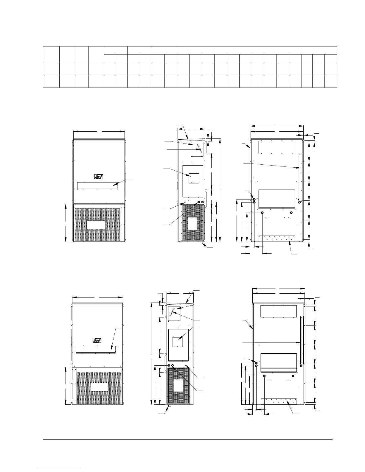
FIGURE 1
Dimensions of Basic Unit for Architectural and Installation Requirements (Nominal)
Width
Depth
Model
(W)
K36A/L
42.075 22.432 84.875 9.88 29.88 15.88 29.88 43.88 13.56 31.66 30.00 32.68 26.94 34.69 32.43 3.37 43.00 23.88 10.00 1.44 16.00 1.88
K42A/L
K48A/L
42.075 22.432 93.000 9.88 29.88 15.88
K60A/L
Height
(D)
All dimensions are in inches. Dimensional drawings are not to scale.
K**A
RIGHT
HAND
UNIT
G
Condenser
Air Outlet
Supply Return
(H)
A B C B E F G I J K L M N O P Q R S T
29.88 43.88
W
ELECTRIC HEAT
C. BREAKER/
DISCONNECT
ACCESS PANEL
(LOCKABLE)
Filter
Access Panel
LOW VOLTAGE
ELECTRICAL
ENTRANCE
HIGH VOLTAGE
ELECTRICAL
ENTRANCE
13.56 37.00 30.00 40.81
BUILT IN
RAIN HOOD
4° PITCH
HEATER
ACCESS
PANEL
Cond.
Air
Inlet
A
I
C
K
35.06
42.81 40.56 3.37 43.00 31.00 10.00 1.44 16.00 10.00
2.13 D
Side Wall
Mounting
Brackets
(Built In)
Top Rain
Flashing
Shipping
Location
Optional
H
Electrical
Entrances
J
L
M
P
E
O
.44
SUPPLY AIR OPENING
RETURN AIR
OPENING
R
S
S
S
S
S
K**L
LEFT
HAND
UNIT
3/4" I.D.
DRAIN HOSE
W
FILTER
ACCESS PANEL
G
Condenser
Air Outlet
FRONT VIEW
2.13
H
3/4" I.D.
DRAIN HOSE
A
I
C
J
K
D
Cond.
Air
Inlet
SIDE VIEW
BUILT IN
RAIN HOOD
4° PITCH
HEATER
ACCESS
PANEL
ELECTRIC HEAT
C. BREAKER/
DISCONNECT
ACCESS PANEL
(LOCKABLE)
LOW VOLTAGE
ELECTRICAL
ENTRANCE
HIGH VOLTAGE
ELECTRICAL
ENTRANCE
Side Wall
Mounting
Brackets
(Built In)
Top Rain
Flashing
Shipping
Location
Optional
Electrical
Entrances
N
L
M
P
N
Q
Back ViewSide ViewFront View
Q
E
O
SUPPLY AIR OPENING
RETURN AIR
OPENING
BACK VIEW
BOTTOM
INSTALLATION
BRACKET
.44
BOTTOM
INSTALLATION
BRACKET
T
MIS-3666 A
R
S
S
S
S
S
T
MIS-3665 A
Manual 2100628
Page 7 of 24
Page 8
D
16"
16"
16"
16"
16"
1
7
8
"
6
1
2
" 6
1
2
"
2
1
8
"
7
8
"
1"
3"
4"
Typ.
4"
Typ.
6
1
2
"
30"
E
16"
A CC
3
1
8
"
B
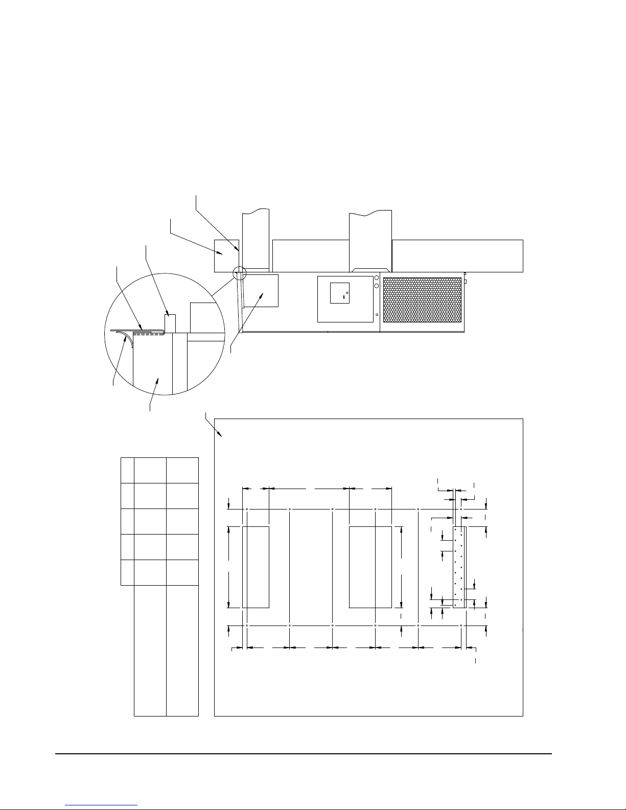
Wall Opening and Hole Location View
RETURN AIR
1
REQUIRED DIMENSIONS TO MAINTAIN
1/4" MIN. CLEARANCE FROM
COMBUSTIBLE MATERIALS
REQUIRED DIMENSIONS TO MAINTAIN
29
DUCT
COMBUSTIBLE MATERIALS
A B C DE
30 1/2
10 1/2
6 1/4 1 1/4 29 3/4
32 12 5 1/2
2
NOTES:
WALL STRUCTURE
1
SUPPLY AIR
IT IS RECOMMENDED THAT A BEAD OF
OPENING
Right Side View
RAIN FLASHING
SILICONE CAULKING BE PLACED BEHIND
RECOMMENDED 1" CLEARANCE FROM
THE SIDE MOUNTING FLANGES AND UNDER
TOP FLASHING AT TIME OF INSTALLATION.
TOP.
PANEL
HEATER ACCESS
FOUR SIDES OF SUPPLY
AIR DUCT IS REQUIRED
FROM COMBUSTABLE
WALL
1/4" CLEARANCE ON ALL
MATERIALS
Supply Opening
FOAM AIR SEAL
SUPPLIED
SEAL WITH BEAD
OF CAULKING ALONG
ENTIRE LENGTH OF
TOP
1
Return Opening
MIS-416 E
Dimension is 21" on 95" tall units.
2
Dimension is 10" on T48H1 & T60H1.
2
Dimension is 6" on T48H1 & T60H1.
3
3
FIGURE 2
Manual 2100-628
Page 8 of 24
MOUNTING INSTRUCTIONS
K36A2, K36L2, K42A2, K42L2, K48A2, K48L2, K60A2, K60L2
Page 9

FIGURE 3
ELECTRIC HEAT CLEARANCE
K36A2, K36L2, K42A2, K42L2, K48A2, K48L2, K60A2, K60L2
NOTE 1: SIDE SECTION VIEW OF SUPPLY AIR DUCT
FOR WALL MOUNTED UNIT SHOWING 1/4 INCH
CLEARANCE TO COMBUSTIBLE SURFACES.
WARNING
A minimum of 1/4 inch clearance must be maintained between
the supply air duct and combustible materials. This is required for
the rst 3 feet of ducting.
It is important to insure that the 1/4 inch minimum spacing is
maintained at all points.
Failure to do this could result in overheating the combustible
material and may result in a re causing damage, injury or death.
Manual 2100628
Page 9 of 24
Page 10

FIGURE 4
DUCT
OPENING
RETURN AIR
SUPPLY AIR
WOOD FRAME WALL INSTALLATION
OPENING
WALL BEFORE
MOUNT ON UNIT
OPENING
BEFORE INSTALLATION
BOTTOM MOUNTING
CONCRETE BLOCK WALL INSTALLATION
BRACKET. MOUNT ON
OPENING
WOOD OR STEEL SIDING
OPENING
INSTALLING UNIT.
RETURN AIR
WALL STRUCTURE
RETURN AIR
SUPPLY AIR
FACTORY SUPPLIED
RAIN FLASHING.
SUPPLY AIR
MIS-548 A
SIDE VIEW
I
A
C
K
E + 1.000
B
1.000
SUPPLY DUCT
OVER FRAME
INTERIOR FINISHED WALL
ALL AROUND DUCT
FRAMING MATERIAL
EXTERIOR FINISH WALL
OPENING
FOR ACTUAL DIMENSIONS.
2 x 4'S, 2 x 6'S &/OR
STRUCTURAL STEEL
ATTACH TO TOP
1.000" CLEARANCE
1.000" CLEARANCE
PLATE OF WALL
C
SEE UNIT DIMENSIONS, FIGURE 2,
OPENING
RETURN DUCT
2 x 6
ATTACH TO BOTTOM
OVER FRAME
PLATE OF WALL
L
THIS STRUCTURAL MEMBER
LOCATED TO MATCH STUD
SPACING FOR REST OF WALL.
A SECOND MEMBER MAY BE
REQUIRED FOR SOME WALLS.
MIS-549 B
ALL AROUND DUCT
WALL MOUNTING INSTRUCTIONS
FIGURE 5
WALL MOUNTING INSTRUCTIONS
Manual 2100-628
Page 10 of 24
Page 11

FIGURE 6
LOWERED
RAISED FLOOR
RAFTERS
SUPPLY AIR
CEILING SURFACE
WALL SLEEVE
RETURN AIR
CLOSET WALL
GRILLE
FLASHING
RETURN AIR
FLASHING
SUPPLY DUCT MAYBE LOCATED IN AN ATTIC
OR BELOW CEILING RAFTERS AS SHOWN
SUPPLY DUCT MAY BE LOCATED IN AN ATTIC
SURFACE
RAFTERS
FINISHED CEILING
SUPPLY AIR DUCT
WALL
OPENING W/ GRILLE
SUPPLY DUCT MAYBE LOCATED IN AN ATTIC
OR BELOW CEILING RAFTERS AS SHOWN
CEILING
RAIN
RETURN AIR
SLEEVE
WALL
SUPPLY AIR DUCT
RAFTERS
RAFTERS
RETURN AIR
OPENING W/ GRILLE
RAIN
FALSE WALL INSTALLATION
DUCTED SUPPLY
GRILLE
OUTSIDE
SPACE
FALSE WALL
RETURN AIR GRILLE
OUTSIDE
OR BELOW CEILING RAFTERS AS SHOWN
FINISHED CEILING SURFACE
RAIN
FLASHING
RAIN
FLASHING
RETURN AT UNITNO DUCT
WALL
SUPPLY AIR DUCT
CLOSET INSTALLATION
RETURN AIR
FINISHED
FINISHED CEILING SURFACE
MIS-550 B
FREE AIR FLOW
OUTSIDE
WALL
OUTSIDE
WALL
SUPPLY AIR DUCT
W/ GRILLE
COMMON WALL MOUNTING INSTALLATIONS
Manual 2100628
Page 11 of 24
Page 12

WIRING – MAIN POWER
Refer to the unit rating plate for wire sizing information
and maximum fuse or circuit breaker size. Each
outdoor unit is marked with a “Minimum Circuit
Ampacity”. This means that the field wiring used must
be sized to carry that amount of current. Depending
on the installed KW of electric heat, there may be
two field power circuits required. If this is the case,
the unit serial plate will so indicate. All models are
suitable only for connection with copper wire. Each
unit and/or wiring diagram will be marked “Use Copper
Conductors Only”. These instructions must be adhered
to. Refer to the National Electrical Code (NEC) for
complete current carrying capacity data on the various
insulation grades of wiring material. All wiring must
conform to NEC and all local codes.
The electrical data lists fuse and wire sizes (75° C
copper) for all models including the most commonly
used heater sizes. Also shown are the number of field
power circuits required for the various models with
heaters.
The unit rating plate lists a “Maximum Time Delay
Relay Fuse” or circuit breaker that is to be used with
the equipment. The correct size must be used for
proper circuit protection and also to assure that there
will be no nuisance tripping due to the momentary high
starting current of the compressor motor.
The disconnect access door on this unit may be locked
to prevent unauthorized access to the disconnect. To
convert for the locking capability, bend the tab located
in the bottom left-hand corner of the disconnect
opening under the disconnect access panel straight
out. This tab will now line up with the slot in the door.
When shut, a padlock may be placed through the hole
in the tab preventing entry.
See “Start Up” section (page 17) for important
information on three phase scroll compressor start ups.
See Table 6 on page 23 for Electrical Specifications.
WIRING – LOW VOLTAGE WIRING
All 230/208V 1 phase equipment has dual primary
voltage transformers. All equipment leaves the factory
wired on 240V tap. For 208V operation, reconnect
from 240V to 208V tap. The acceptable operating
voltage range for the 240 and 208V taps are:
240 253 – 216
208 220 – 187
NOTE: The voltage should be measured at the field
TAP RANGE
power connection point in the unit and while
the unit is operating at full load (maximum
amperage operating condition).
18 guage copper, color-coded thermostat cable is
recommended. See Figure 7 on page 14 for thermostat
connections.
Low Voltage Connection
These units use a 24-volt AC low voltage circuit.
The “RT” terminal is the 24V transformer output,
and the “R” terminal is the 24VAC hot terminal for
the operation of the equipment. “RT” and “R” are
connected with brass jumper bar which can be removed
and “RT” and “R” connected to external NC (normally
closed) contact such as a fire/smoke detector that will
cause immediate shutdown of the equipment upon
activation.
“C” terminal is grounded.
“G” terminal is the fan input.
“Y” terminal is the compressor input for cooling
“W1” terminal is the 1st stage electric heat.
TABLE 1
LOW VOLTAGE CONNECTIONS
FOR DDC CONTROL
Fan Only Energize G
Cooling Mode Energize Y, G
Heating Mode Energize W1, G
TABLE 2
WALL THERMOSTAT
Part Number Predominate Features
8403-057
(TH3110D1040)
8403-058
(TH5220D1151)
8403-059
(TH5220D1219/U)
8403-060
(1120-445)
1 stage Cool, 1 stage Heat
Electronic Non-Programmable
Auto or Manual changeover
2 stage Cool, 2 stage Heat
Electronic Non-Programmable
HP or Conventional (Default: HP)
Auto or Manual changeover
2 stage Cool, 2 stage Heat
Electronic Non-Programmable
HP or Conventional (Default: AC)
Auto or Manual changeover
3 stage Cool; 3 stage Heat
Programmable/Non-Programmable
Electronic
HP or Conventional
Auto or Manual changeover
Dehumidification Output
TABLE 3
THERMOSTAT WIRE SIZE
Transformer
VA
55 2.3
FLA Wire Gauge
20 gauge
18 gauge
16 gauge
14 gauge
12 gauge
Maximum
Distance
(Feet)
45
60
100
160
250
Manual 2100-628
Page 12 of 24
Page 13

HUMIDITY CONTROL OPTION
When two units are controlled and connected with
the MV4001K-B, they can be adapted to perform
dehumidification with the addition of a simple humidity
controller that closes-on-rise, and is connected to
terminals "H1" and "H2" on the main controller board
(see Figure 8 on page 15). Recommended is Bard Part
# 8403-038 (H600A 1014). NOTE: Both HVAC units
must be equipped with electric resistance heat for this
sequence to work properly.
1. Temperature control always has priority over
dehumidification. If there is any stage of cooling
demand active, the dehumidification sequence is
locked out.
2. If all stages of cooling are satisfied, and relative
humidity is above the set point of the humidity
controller.
a. The Green "Dehumid Operation Light" will come
on, and the lag unit compresser and blower will
operate until the set point of humidty controller
is satisfied (or cancelled by a call for cooling).
b. If the space temperature drops to 19.4°C, the
electric heater of the lead unit will cycle to help
maintain building temperature. It will cycle off
at 20.6°C.
c. If the space temperature drops to 17.8°C,
the "Stage 2 Heating Light" will come on,
and the lag unit compressor operation for
dehumidification mode will terminate until the
building temperature rises above18.3°C from
the 1st Stage heat and building load. The
Green "Dehumidification Light" will stay on
during this sequence, and when 2nd Stage
Heating light is "OFF", the compressor is "ON".
The electric resistance heater in the lag unit is
locked out in dehumidification mode.
Lag Unit outputs G, Y1, and Y2 are all switched
one during dumidification sequence. This is true
for both alternating and non-alternating controller
configurations.
Manual 2100628
Page 13 of 24
Page 14

FIGURE 7
THERMOSTAT CONNECTIONS
Manual 2100-628
Page 14 of 24
Page 15

FIGURE 8
CU, AND SILVER MUST
NOTE: ALL SENSORS ARE
POLARITY SENSITIVE. COPPER
LEAD MUST CONNECT TO
LEAD TO AG
48VDC
-
+
CIRCUIT
BREAKER
2
E
F
2
3
E
F
3
41
44
42
MV4001
CONTROLLER
REM 2
REM 1
LOCAL
AG
H2
H1
CU
AG
CU
AG
CU
F2
F1
C
W
Y1
Y2
MAIN BOARD
HUMIDITY
TERMINAL BLOCK
R
C
Y
F
A
4
5
6
8
G
MV4001 UNIT 1
TERMINAL BLOCK
8
6
5
4
A
F
Y
C
R
9
7
8
6
5
4
A
F
Y
C
R
9
3
10
2
E
G
Y2
Y1
W
1
Y
C
F
A
9
7
R
4
5
6
W
8
Y1
Y2
G
10
3
2
E
1
G
Y2
Y1
W
9
MV4001 UNIT 2
BOARD
ADVANCE
G2
G1
COPPER
SILVER
COPPER
SILVER
COPPER
SILVER
+
_
R
C
ALARM
R
42
41
2 COMP RUN ALARM
TERMINAL BLOCK
44
43
2
1
Rt
GEN RUN ALARM/
ECON SHUTDOWN
NC CONTACTS
OPEN ON ALARM
Rt
REMOVE JUMPER FOR
COMP DISABLE FEATURE
2
REMOVE JUMPER WHEN
CONNECTING GEN CONTACT
3
REMOVE JUMPER WHEN CONNECTING
FIRE SHUTDOWN CONTACT
1
NC CONTACTS
OPEN ON ALARM
1
3
43
MV4001
FIRE/SMOKE
AC UNIT 1
ALARM (NC)
OPERATE ON DC POWER ONLY
AC UNIT 2
"NC" CONTACTS -
ALARM CIRCUIT
MIS-3572A
LOCKOUT ALARM
LOCKOUT ALARM
REMOVE
SMOKE
UNIT 2
JUMPER
1
ALARM (NC)
OPEN ON ALARM
1
FIRE/
35 FOOT TEMPERATURE
SENSORS, BARD PART
NUMBER 8612-023A
UNIT 1
OPTIONAL FIELD INSTALLED
OPTIONAL FIELD INSTALLED
HUMIDITY CONTROLLER
"NO" CONTACTS - CLOSE ON RISE
DIRTY FILTER
JUMPER
DIRTY FILTER
48VDC
OR CONTROLLER WILL NOT
OPTIONAL
48VDC
2
1
MUST BE CONNECTED AS SHOWN
2
ALARM - REQUIRES "J" CONTROL MODULE IN
A/C UNITS
THE "E" AND "F" CONNECTION FOR EMERGENCY
VENTILATION ARE AVAILABLE
NOTE: DC BACK-UP POWER
IS POLARITY SENSITIVE AND
REFRIGERANT PRESSURE LOCKOUT
REMOVE
MV4001K-B CONTROLLER CONNECTIONS
1-STAGE (K**A/K**L SERIES) AIR CONDITIONERS – NO ECONOMIZER
MIS-3572A
See Humidity
Control Option on
page 13
Manual 2100628
Page 15 of 24
Page 16

START UP
THESE UNITS REQUIRE R-410A
REFRIGERANT AND POLYOL ESTER
OIL.
GENERAL
1. Use separate service equipment to avoid cross
contamination of oil and refrigerants.
2. Use recovery equipment rated for R-410A
refrigerant.
3. Use manifold gauges rated for R-410A (800
psi/250 psi low).
4. R-410A is a binary blend of HFC-32 and HFC-125.
5. R-410A is nearly azeotropic - similar to R-22 and
R-12. Although nearly azeotropic, charge with
liquid refrigerant.
6. R-410A operates at 40-70% higher pressure than
R-22, and systems designed for R-22 cannot
withstand this higher pressure.
7. R-410A has an ozone depletion potential of zero,
but must be reclaimed due to its global warming
potential.
8. R-410A compressors use polyolester oil.
9. Polyol Ester oil is hygroscopic; it will rapidly absorb
moisture and strongly hold this moisture in the oil.
10. A liquid line dryer must be used - even a deep
vacuum will not separate moisture from the oil.
11. Limit atmospheric exposure to 15 minutes.
12. If compressor removal is necessary, always plug
compressor immediately after removal. Purge with
small amount of nitrogen when inserting plugs.
TOPPING OFF SYSTEM CHARGE
If a leak has occurred in the system, Bard
Manufacturing recommends reclaiming, evacuating (see
criteria above), and charging to the nameplate charge.
If done correctly, topping off the system charge can be
done without problems.
With R-410A, there are no significant changes in the
refrigerant composition during multiple leaks and
recharges. R-410A refrigerant is close to being an
azeotropic blend (it behaves like a pure compound
or single component refrigerant). The remaining
refrigerant charge, in the system, may be used after
leaks have occurred and then “top-off” the charge by
utilizing the pressure charts on the inner control panel
cover as a guideline.
REMEMBER: When adding R-410A refrigerant, it must
come out of the charging cylinder/tank as a liquid to
avoid any fractionation, and to ensure optimal system
performance. Refer to instructions for the cylinder that
is being utilized for proper method of liquid extraction.
WARNING
Failure to conform to these practices
could lead to damage, injury or death.
SAFETY PRACTICES
1. Never mix R-410A with other refrigerants.
2. Use gloves and safety glasses, Polyol Ester oils can
be irritating to the skin, and liquid refrigerant will
freeze the skin.
3. Never use air and R-410A to leak check; the
mixture may become flammable.
4. Do not inhale R-410A. The vapor attacks
the nervous system, creating dizziness, loss
of coordination and slurred speech. Cardiac
irregularities, unconsciousness and ultimate death
can result from breathing this concentration.
5. Do not burn R-410A. This decomposition
produces hazardous vapors. Evacuate the area if
exposed.
6. Use only cylinders rated DOT4BA/4BW 400.
7. Never fill cylinders over 80% of total capacity.
8. Store cylinders in a cool area, out of direct
sunlight.
9. Never heat cylinders above 125°F.
10. Never trap liquid R-410A in manifold sets, gauge
lines or cylinders. R-410A expands significantly
at warmer temperatures. Once a cylinder or line is
full of liquid, any further rise in temperature will
cause it to burst.
Manual 2100-628
Page 16 of 24
Page 17

IMPORTANT INSTALLER NOTE
PHASE MONITOR
For improved start up performance wash the indoor coil
with a dish washing detergent.
HIGH PRESSURE SWITCH
All K**A/K**L wall mounted air conditioner series
models are supplied with a remote reset for the high
and low pressure switch. If tripped, this pressure
switch may be reset by turning the thermostat off then
back on again.
THREE PHASE SCROLL COMPRESSOR
START UP INFORMATION
Scroll compressors, like several other types of
compressors, will only compress in one rotational
direction. Direction of rotation is not an issue with
single phase compressors since they will always start
and run in the proper direction.
However, three phase compressors will rotate in either
direction depending upon phasing of the power.
Since there is a 50-50 chance of connecting power
in such a way as to cause rotation in the reverse
direction, verification of proper rotation must be made.
Verification of proper rotation direction is made by
observing that suction pressure drops and discharge
pressure rises when the compressor is energized.
Reverse rotation also results in an elevated sound level
over that with correct rotation, as well as substantially
reduced current draw compared to tabulated values.
Verification of proper rotation must be made at the
time the equipment is put into service. If improper
rotation is corrected at this time, there will be no
negative impact on the durability of the compressor.
However, reverse operation for over one hour may have
a negative impact on the bearing due to oil pump out.
All units with three phase scroll compressors are
equipped with a 3 phase line monitor to prevent
compressor damage due to phase reversal.
The phase monitor in this unit is equipped with two
LEDs. If the Y signal is present at the phase monitor
and phases are correct the green LED will light.
If phases are reversed, the red fault LED will be lit and
compressor operation is inhibited.
If a fault condition occurs, reverse two of the supply
leads to the unit. Do not reverse any of the unit factory
wires as damage may occur.
CONDENSER FAN OPERATION
NOTE: All models covered by this manual are
equipped with a low ambient control (LAC);
on start up, the condenser fan motor will have
delayed start until system refrigerant operating
pressure builds up. After starting, the fan
motor may or may not cycle depending upon
ambient conditions. This is normal operation.
SERVICE HINTS
1. Caution owner/operator to maintain clean air
filters at all times. Also, not to needlessly close
off supply and return air registers. This reduces
airflow through the system, which shortens
equipment service life as well as increasing
operating costs.
2. Check all power fuses or circuit breakers to be sure
they are the correct rating.
3. Periodic cleaning of the outdoor coil to permit full
and unrestricted airflow circulation is essential.
NOTE: If compressor is allowed to run in reverse
rotation for an extended period of time, the
compressor’s internal protector will trip.
All three phase compressors are wired identically
internally. As a result, once the correct phasing
is determined for a specific system or installation,
connecting properly phased power leads to the same
Fusite terminal should maintain proper rotation
direction.
The direction of rotation of the compressor may be
changed by reversing any two line connections to the
unit.
Manual 2100628
Page 17 of 24
Page 18

SEQUENCE OF OPERATION
COOLING – Circuit R-Y makes at thermostat pulling
in compressor contactor, starting the compressor and
outdoor motor. (See NOTE on previous page under
Condenser Fan Operation if equipped with Low Ambient
Control.) The G (indoor motor) circuit is automatically
completed by the thermostat on any call for cooling
operation or can be energized by manual fan switch
on subbase for constant air circulation. On a call for
heating, circuit R-W1 make at the thermostat pulling in
heat contactor for the strip heat and blower operation.
On a call for second stage heat, R-W2 makes bringing
on second heat contactor, if so equipped.
COMPRESSOR CONTROL MODULE
The compressor control module is standard on all
models covered by this manual. The compressor
control module is an anti-short cycle/lockout timer with
high and low pressure switch monitoring and alarm
relay output.
Adjustable Delay On Make And Break Timer
On initial power up or anytime power is interrupted to
the unit, the delay on make period begins, which will
be 2 minutes plus 10% of the delay on break setting.
When the delay on make is complete and the high
pressure switch and low pressure switch is closed, the
compressor contactor is energized. Upon shutdown,
the delay on break timer starts and prevents restart
until the delay on break and delay on make periods
have expired.
During routine operation of the unit with no power
interruptions, the compressor will operate on demand
with no delay.
High Pressure Switch and Lockout Sequence
If the high pressure switch opens, the compressor
contactor will de-energize immediately. The lockout
timer will go into a soft lockout and stay in soft lockout
until the high pressure switch closes and the delay on
break time has expired. If the high pressure switch
opens again in this same operating cycle, the unit will
go into manual lockout condition and the alarm relay
circuit will energize. Recycling the wall thermostat
resets the manual lockout.
Recycling the wall thermostat resets the manual
lockout.
Alarm Relay Output
Alarm terminal is output connection for applications
where alarm relay is employed. This terminal is
powered whenever the compressor is locked out due to
HPC or LPC sequences as described.
NOTE: Both high and low pressure switch controls are
inherently automatic reset devices. The high
pressure switch and low pressure switch cut
out and cut in settings are fixed by specific air
conditioner unit model. The lockout features,
both soft and manual, are a function of the
Compressor Control Module.
ADJUSTMENTS
Adjustable Delay on Make and Delay on Break Timer
The potentiometer is used to select Delay on Break
time from 30 seconds to 5 minutes. Delay on
Make (DOM) timing on power-up and after power
interruptions is equal to 2 minutes plus 10% of Delay
on Break (DOB) setting:
0.5 minute (30 seconds) DOB = 123 second DOM
1.0 minute (60 seconds) DOB = 126 second DOM
2.0 minute (120 seconds) DOB = 132 second DOM
3.0 minute (180 seconds) DOB = 138 second DOM
4.0 minute (240 seconds) DOB = 144 second DOM
5.0 minute (300 seconds) DOB = 150 second DOM
During routine operation of the unit with no power
interruptions, the compressor will operate on demand
with no delay.
Typical Settings for Dual Unit Installation:
Unit 1: DOB set at 2 minutes; DOM is 132 seconds
Unit 2: DOB set at 4 minutes; DOM is 144 seconds
PRESSURE SERVICE PORTS
High and low pressure service ports are installed on
all units so that the system operating pressures can be
observed. A cooling pressure table can be found on
page 22.
Low Pressure Switch, Bypass, and Lockout Sequence
If the low pressure switch opens for more than 120
seconds, the compressor contactor will de-energize
and go into a soft lockout. Regardless the state of the
low pressure switch, the contactor will reenergize after
the delay on make time delay has expired. If the low
pressure switch remains open, or opens again for longer
than 120 seconds, the unit will go into manual lockout
condition and the alarm relay circuit will energize.
Manual 2100-628
Page 18 of 24
Page 19

SERVICE
FAN BLADE SETTING DIMENSIONS
Shown in Figure 9 is the correct fan blade setting for
proper air delivery across the outdoor coil. Refer to
Table 4 for unit specific dimension.
Any service work requiring removal or adjustment in the
fan and/or motor area will require that the dimensions
below be checked and blade adjusted in or out on the
motor shaft accordingly.
FIGURE 9
FAN BLADE SETTING
AIRFLOW
"A"
MIS-1724
R-410A REFRIGERANT CHARGE
This unit was charged at the factory with the quantity
of refrigerant listed on the serial plate. AHRI capacity
and efficiency ratings were determined by testing with
this refrigerant charge quantity.
The pressure table on page 22 shows nominal
pressures for the units. Since many installation
specific situations can affect the pressure readings,
this information should only be used by certified
technicians as a guide for evaluating proper system
performance. They shall not be used to adjust charge.
If charge is in doubt, reclaim, evacuate and recharge
the unit to the serial plate charge.
REMOVAL OF FAN SHROUD
1. Disconnect all power to the unit.
2. Remove the screws holding both grilles, one on
each side of unit, and remove grilles.
3. Remove screws holding fan shroud to condenser
and bottom. Nine (9) screws.
4. Unwire condenser fan motor.
5. Slide complete motor, fan blade, and shroud
assembly out the left side of the unit.
TABLE 4
FAN BLADE DIMENSION
Model
K36A2/K36L2
K42A2/K42L2
K48A2/K48L2
K60A2/K60L2
6. Service motor/fan as needed.
7. Reverse steps to reinstall.
Dimension
A
1.75"
Manual 2100628
Page 19 of 24
Page 20

TROUBLESHOOTING CONSTANT TORQUE ECM MOTORS
FIGURE 10
NOTE: Bard Models PA13242; PA13302; PA13362-A, -B; PA13422-A, -B, -C; PA13482-A, -B, -C; PA13602-A, -B, -C
contain the X13-Series Motors.
TROUBLESHOOTING GE X13-SERIES ECM2.3™ MOTORS
If the Motor is Running
1. It is normal for the motor to rock back and forth on start up.
Do not replace the motor if this is the only problem identified.
2. If the system is excessively noisy, does not appear to change
speeds in response to a demand (Heat, Cool, Other), or is having
symptoms during the cycle such as tripping limit or freezing coil,
check the following:
a. Wait for programmed delays to time out.
b.Ensure that the motors control inputs are wired to the factory
supplied wiring diagram to insure motor is getting proper
control signals and sequencing.
c. Remove the filter and check that all dampers, registers, and
grilles are open and free flowing. If removing the filters
corrects the problem, clean or replace with a less restrictive
filter. Also check and clean the blower wheel or coil as
necessary.
d.Check the external static pressure (total of both supply and
return) to insure that you are within the ranges as listed on the
unit serial plate. If higher than allowed, additional duct work
is needed.
e. If the motor does not shut off at the end of the cycle, wait for
any programmed delays to time out (no more than 90
seconds). Also make sure that there is no call for
“Continuous Fan” on the "G" terminal.
f. If the above diagnostics do not solve the problem, confirm the
voltage checks in the next section below, then continue with
the “Model X13 Communication Diagnostics”.
If the Motor is Not Running
1. Check for proper high voltage and ground at the (L/L1) (G) (N/
L2) connections at the motor (see Figure 10). Correct any voltage
issues before proceeding to the next step. The X13 Motor is voltage
specific. Only the correct voltage should be applied to the proper
motor. Input voltage within plus or minus 10% of the nominal 230
VAC is acceptable.
2. If the motor has proper high voltage and ground at the (L/L1)
(G) (N/L2) connections, then continue with the “Model X13
Communication Diagnostics”.
IF THE MOTOR IS RUNNING
1. It is normal for the motor to rock back and forth
on start up. Do not replace the motor if this is the
only problem identified.
2. If the system is excessively noisy, does not appear
to change speeds in response to a demand (Heat,
Cool, Other) or is having symptoms during the
cycle such as tripping limit or freezing coil, check
the following:
a. Wait for programmed delays to time out.
b. Confirm that the motors control inputs are
wired per the factory supplied wiring diagram
to ensure motor is getting proper control
signals and sequencing.
c. Remove the filter and check that all dampers,
registers and grilles are open and free flowing.
If removing the filters corrects the problem,
clean or replace with a less restrictive filter.
Also check and clean the blower wheel or coil
as necessary.
d. Check the external static pressure (total of
both supply and return) to ensure that you are
within the ranges as listed on the unit serial
plate. If higher than allowed, additional duct
work is needed.
FIGURE 10
MOTOR HIGH VOLTAGE CONNECTIONS
e. If the motor does not shut off at the end of the
cycle, wait for any programmed delays to time
out (no more than 90 seconds). Also make
sure that there is no call for “Continuous Fan”
on the “G” terminal.
f. If the above diagnostics do not solve the
problem, confirm the voltage checks in the
next section below, then continue with the
“Communication Diagnostics” on the following
page.
IF THE MOTOR IS NOT RUNNING
1. Check for proper high voltage and ground at the
(L/L1) (G) (N/L2) connections at the motor (see
Figure 10). Correct any voltage issues before
proceeding to the next step. The motor is voltage
specific. Only the correct voltage should be
applied to the proper motor. Input voltage within
plus or minus 10% of the nominal 230 VAC is
acceptable.
2. If the motor has proper high voltage and ground at
the (L/L1) (G) (N/L2) connections, then continue
with the “Communication Diagnostics” on the
following page.
↓
L2 LINE
POWER
EARTH
GROUND
↓
L1 LINE
POWER
NOTE: MOTOR IS CONSTANTLY
POWERED BY LINE VOLTAGE
Manual 2100-628
Page 20 of 24
Page 21

COMMUNICATION DIAGNOSTICS
FIGURE 11
™
MOTORS
CONT’D.
2. Initiate a demand from the thermostat and check the
voltage between the common and the appropriate motor
terminal (1-5). ("G" input is typically on terminal #1, but
refer to wiring diagram!)
a. If the low voltage communication is not present, check
the demand from the thermostat. Also check the
output terminal and wire(s) from the terminal strip or
control relay(s) to the motor.
b. If the motor has proper high voltage as identified
above (Motor not Running #1), and proper low voltage
to a programmed terminal, and is not operating, the
motor is failed, and will require replacement.
The motor is communicated through 24 VAC low
voltage (Thermostat Control Circuit Wiring).
1. Start with unit wiring diagram to confirm proper
connections and voltage (see Figure 11).
2. Initiate a demand from the thermostat and
check the voltage between the common and the
appropriate motor terminal (1-5). (“G” input
is typically on terminal #1, but refer to wiring
diagram.)
24VAC Co mmo n
MOTOR LOW VOLTAGE CONNECTIONS
FIGURE 11
a. If the low voltage communication is not
present, check the demand from the
thermostat. Also check the output terminal
and wire(s) from the terminal strip or control
relay(s) to the motor.
b. If the motor has proper high voltage as
identified above (Motor not Running #1) and
proper low voltage to a programmed terminal
yet is not operating, the motor is failed and
will require replacement.
24VAC "R" Signal throug h
thermostat output.
24VAC Co mmo n
24VAC "R" Signal throug h
thermostat output.
Manual 2100628
Page 21 of 24
Page 22

TABLE 5
COOLING PRESSURE TABLE
OUTDOOR AMBIENT TEMPERATURE °C
Model
K36*2
K42*2
K48*2
K60*2
Low side pressure ± 4 PSIG
High side pressure ± 10 PSIG
Tables are based upon rated CFM (airflow) across the evaporator coil. If there is any doubt as to correct operating
charge being in the system, the charge should be removed and the system evacuated and recharged to serial plate
charge weight.
NOTE:
Pressure table based on high speed condenser fan operation. If condensing pressures appear
elevated, check condenser fan wiring. See “Condenser Fan Operation” (page 17).
Return Air
Temperature °C
27° DB
19° WB
27° DB
19° WB
27° DB
19° WB
27° DB
19° WB
27° DB
19° WB
27° DB
19° WB
27° DB
19° WB
27° DB
19° WB
Pressure 35 37 39 41 43 45 47 49 51 53 55
Low Side
High Side
Low Side
High Side
Low Side
High Side
Low Side
High Side
Low Side
High Side
Low Side
High Side
Low Side
High Side
Low Side
High Side
143 145 147 148 150 152 154 156 158 160 162
368 388 408 429 449 470 489 509 528 547 566
143 145 147 149 151 153 155 158 160 162 164
368 389 409 430 451 472 492 511 530 549 568
149 149 149 149 149 149 150 153 156 159 162
377 396 415 435 454 473 494 517 539 562 585
151 152 152 153 154 154 156 159 162 165 168
378 397 416 436 455 474 495 519 542 565 589
Manual 2100-628
Page 22 of 24
Page 23

TABLE 6
ELECTRICAL SPECIFICATIONS
Single Circuit
Model
K36A2-A0Z
-A05 1
K36A2-N0Z
-N05 1 9.8 15 14 14
K42A2-A0Z
-A05 1
K42A2-N0Z
-N05 1
K48A2-A0Z
-A05 1
K48A2-N0Z
-N05 1 12.7 15 14 14
K60A2-A0Z
-A05 1
K60A2-N0Z
-N05 1 14.1 20 12 12
Model
Rated Volts,
Hertz & Phase
208/230-60-1
400-60-3
208/230-60-1
400-60-3
208/230-60-1
400-60-3
208/230-60-1
400-60-3
Rated Volts,
Hertz & Phase
No. Field
Power
Circuits
1
1 8.2 10 14 14
1
1
1
1 12.7 15 14 14
1
1 14.1 20 12 12
No. Field
Power
Circuits
Minimum
Circuit
Ampacity
Minimum
Circuit
Ampacity
Maximum
External Fuse
or Ckt. Brkr.
Single Circuit
Maximum
External Fuse
or Ckt. Brkr.
Field Power
Wire Size
Field Power
Wire Size
Ground Wire
Ground Wire
K36L2-A0Z
K36L2-N0Z
K42L2-A0Z
K42L2-N0Z
K48L2-A0Z
K48L2-N0Z
K60L2-A0Z
K60L2-N0Z
These "Minimum Circuit Ampacity" values are to be used for sizing the field power conductors. Refer to the
National Electric Code (latest version), Article 310 for power conductor sizing.
Maximum Size of the time delay fuse or circuit breaker for protection of field wiring conductors.
Based on 75°C copper wire. All wiring must conform to the National Electric Code and all local codes.
208/230-60-1
-A05 1
-N05 1 9.8 15 14 14
-A05 1
-N05 1
-A05 1
-N05 1 12.7 15 14 14
-A05 1
-N05 1 14.1 20 12 12
400-60-3
208/230-60-1
400-60-3
208/230-60-1
400-60-3
208/230-60-1
400-60-3
1
1 8.2 10 14 14
1
1
1
1 12.7 15 14 14
1
1 14.1 20 12 12
Manual 2100628
Page 23 of 24
Page 24

TABLE 7
RECOMMENDED AIRFLOW
Model
K36A, K36L 1100 .15 930 - 1350
K42A, K42L 1300 .20 1485 - 1070
K48A, K48L 1550 .20 1750 - 1285
K60A, K60L 1600 .20 1890 - 1335
* Rated CFM and ESP on factory speed connection.
Nominal
Rated
CFM *
Nominal
Rated
ESP *
Recommended
Airflow Range
TABLE 8
INDOOR BLOWER PERFORMANCE
Model K36 K42 K48 K60
ESP
0)
(Inch H
2
0.1 1100 1300 1550 1650
0.2 1068 1257 1485 1587
0.3 1030 1208 1413 1518
0.4 983 1149 1313 1440
0.5 924 1079 1240 1350
NOTE: Application of required supply and return grilles
will result in approximately 0.10" ESP restriction.
TABLE 9
MAXIMUM ESP OF OPERATION
ELECTRIC HEAT ONLY
Model
Outlet FRONT
Speed High Low
-A0Z
-A05
-N0Z
-N06
Values shown are for units equipped with standard
1-inch throwaway filter or 1-inch washable filter.
Derate ESP by .15 for 2-inch pleated filters.
K36A/L, K42A/L,
K48A/L, K60A/L
.50
.50
.50
.50
.50
.50
.50
.50
TABLE 10
ELECTRIC HEAT
KW
5 20.8 17,065 18.1 12,800 -- --
6 -- -- -- -- 9.0 21,330
240V-1 208V-1 400V-3
Amps BTUH Amps BTUH Amps BTUH
Manual 2100-628
Page 24 of 24
 Loading...