

Bard I36Z1-A, I36Z1-B, I36Z1-C, I48Z1-A, I48Z1-B Installation Instructions Manual
...
INSTALLATION INSTRUCTIONS
MIS-3116
I-TEC SERIES
PACKAGED HEAT PUMP
Models:
I36Z1-A
I36Z1-B
I36Z1-C
I48Z1-A
I48Z1-B
I48Z1-C
I60Z1-A
I60Z1-B
I60Z1-C
Bard Manufacturing Company, Inc.
Bryan, Ohio 43506
www.bardhvac.com
Manual: 2100-578E
Supersedes: 2100-578D
Date: 11-10-14
Page 1 of 41

CONTENTS
Getting Other Information and Publications
For more information, contact these publishers: ........... 3
General ......................................................................... 4
ANSIZ535.5Denitions................................................ 4
I-TEC General Information
I-TEC Model Nomenclature .......................................... 5
Shipping Damage ......................................................... 8
Unit Removal From Skid ............................................... 8
Handling Unit After Removal From Skid ....................... 8
Required Steps after Final Placement ........................ 10
Minimum Installation Clearances ................................ 10
Securing Unit to Structure ........................................... 10
Seismic Considerations .............................................. 10
Rubber Mat ................................................................. 10
Duct Work ................................................................... 16
Filters .......................................................................... 16
Condensate Drain ....................................................... 17
With No Vent Option ................................................... 17
With Commercial Room Ventilator .............................. 17
Installation Instructions
Mounting the Unit ........................................................ 20
Wiring — Main Wiring .................................................. 20
Wiring — Low Voltage Wiring ...................................... 21
Low Voltage Connections ........................................... 21
Start Up
R-410A Refrigerant Required ......................................... 26
Topping Off System Charge ........................................... 26
Safety Practices.............................................................. 26
Description of Standard Equipment ................................ 26
Important Installer Note .................................................. 26
Phase Monitor ................................................................ 26
Three Phase Scroll Compressor .................................... 26
Service Hints .................................................................. 26
Sequence of Operation................................................... 27
Pressure Service Ports ................................................... 27
Defrost Cycle .................................................................. 28
I-TEC Commercial Room Ventilator System
General Description .................................................... 29
Control Wiring ............................................................. 29
Recommended Control Sequences ............................ 29
Setting the Ventilation CFM Levels ............................. 29
Annual Maintenance ..................................................... 33
Troubleshooting
Solid State HP Control Troubleshooting Procedure ....... 34
Checking Temperature Sensor ....................................... 35
Troubleshooting ECM™ 142R Motor .....................36 & 37
Replacing the Motor .......................................................37
Troubleshooting Indoor ECM™ Motor ....................38 & 39
Fan Blade Setting Dimensions ....................................... 40
Refrigerant Charge ......................................................... 40
Figures
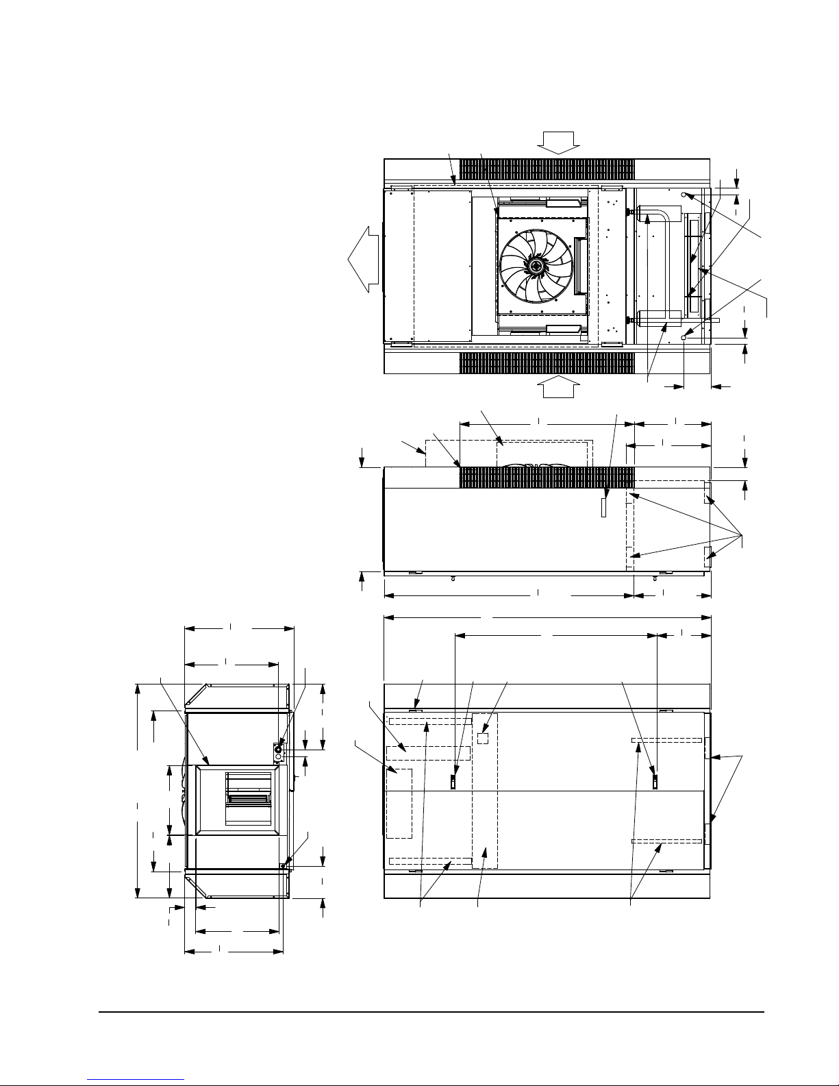
Figure 1 Unit Dimensions ........................................... 7
Center of Gravity .......................................... 8
Figure 2A Unit on Lift .................................................... 8
Figure 2B Unit Side....................................................... 8
Wall Mounting Bracket Location ................................... 10
Bracket Wall Sect. View & Wood Framed Install ...........11
Figure 3 Compressor Shipping Bolts........................ 12
Figure 4 Removal of Air Duct ................................... 12
Figure 5A Ducted Application ..................................... 13
Figure 5B 3" Riser Application .................................... 13
Figure 5C 6" Riser Application .................................... 14
Figure 5D Req'd. Clearances & Rec. Access ............. 15
Figure 6 Supply Duct Connections ........................... 16
Figure 7 Filter Location............................................. 16
Figure 8 Drain Locations .......................................... 17
Figures 9A & 9B Unit Mounting ............................18 & 19
Figure 10 Component Location .................................. 20
Figure 11 Basic Heat Pump w/No Vent Pkg. .............. 22
Figure 12 Heat Pump w/CRV, without CO
Figure 13 Heat Pump with CRV & CO
Figure 14 Defrost Cycle .............................................. 28
Figure15 CRVMotorSpeed/CFMConguration ....... 30
Figure 16 CRV Speed Change Terminal Access ........ 31
Figure17 VentilationAirowDiagram ........................ 32
Figure 18 Control Disassembly .................................. 39
Figure 19 Winding Test ............................................... 39
Figure 20 Drip Loop.................................................... 39
Figure 21 Control Connector Motor Half .................... 40
Control .... 23
2
Control .......... 24
2
Tables
Table 1 Factory Built-In Electric Heat Table ............... 5
Table 1A Indoor Blower Performance........................... 5
Table2 Elec.Specications ....................................... 6
Center of Gravity Table .................................. 8
Table 3 Operating Voltage Range ............................ 21
Table 4 Wall Thermostats ......................................... 21
Table 5 Troubleshooting ........................................... 34
Table 6 Temperature vs Resistance of
Temperature Sensor .................................... 35
Table 7 Troubleshooting ECM™ 142R .................... 37
Table 8 Cooling Mode .............................................. 37
Table 9 Heat Pump Mode ........................................ 37
Troubleshooting ECM™ Blower Motors ....................... 40
Power Connector ......................................................... 40
Table 10A Pressures: Full Load Cooling
Table 10B Pressures: Full Load Heating
Table 11A Pressures: Part Load Cooling
Table 11B Pressures: Part Load Heating
I36Z-I60Z ..... 41
I36Z-I60Z ..... 41
I36Z-I60Z .... 41
I36Z-I60Z .... 41
Manual 2100-578E
Page 2 of 41

GETTING OTHER INFORMATION AND PUBLICATIONS
These publications can help you install the air
conditioner or heat pump. You can usually nd these
at your local library or purchase them directly from the
publisher. Be sure to consult current edition of each
standard.
National Electrical Code ...................... ANSI/NFPA 70
Standard for the Installation ...............ANSI/NFPA 90A
of Air Conditioning and Ventilating Systems
Standard for Warm Air .......................ANSI/NFPA 90B
Heating and Air Conditioning Systems
Load Calculation for ..................... ACCA Manual J or
Winter and Summer Manual N
Air Conditioning
Low Pressure, Low Velocity ......... ACCA Manual D or
Duct System Design Manual Q
Winter and Summer Air Conditioning
FOR MORE INFORMATION, CONTACT
THESE PUBLISHERS:
ACCA Air Conditioning Contractors of America
1712 New Hampshire Avenue
Washington, DC 20009
Telephone: (202) 483-9370
Fax: (202) 234-4721
ANSI American National Standards Institute
11 West Street, 13th Floor
New York, NY 10036
Telephone: (212) 642-4900
Fax: (212) 302-1286
ASHRAE American Society of Heating, Refrigeration,
and Air Conditioning Engineers, Inc.
1791 Tullie Circle, N.E.
Atlanta, GA 30329-2305
Telephone: (404) 636-8400
Fax: (404) 321-5478
NFPA National Fire Protection Association
Batterymarch Park
P.O. Box 9101
Quincy, MA 02269-9901
Telephone: (800) 344-3555
Fax: (617) 984-7057
Manual 2100-578E
Page 3 of 41
GENERAL
The equipment covered in this manual is to be installed
by trained, experienced service and installation
technicians.
The I-TEC must be installed with the Bard
manufactured IWS wall sleeve and ILG louver
grille accessories. These are sold as separate
accessories. Any substitutions will void the
manufacturer’s warranty.
The unit is designed for use with or without ductwork.
For use without ductwork, Plenum Box IPBDFZ18color (18" height) or IPBDFZ12-color (12" height) is
recommended.
These instructions explain the recommended method
to install the air cooled self-contained unit and the
electrical connections to it.
These instructions and any instructions packaged
with any separate equipment required to make up the
entire heating and air conditioning system should be
carefully read before beginning the installation. Note
particularly “Start Procedure” and any tags and/or
labels attached to the equipment.
While these instructions are intended as a general
recommended guide, they do not supersede any national
and/or local codes in any way. Authorities having
jurisdiction should be consulted before the installation is
made. See Page 3 for information on codes and standards.
Size of unit for a proposed installation should be
based on heat loss or heat gain calculation made
according to methods of Air Conditioning Contractors
of America (ACCA). The air duct should be installed
in accordance with the Standards of the National Fire
Protection Systems of Other Than Residence Type,
NFPA No. 90A, and Residence Type Warm Air Heating
and Air Conditioning Systems, NFPA No. 90B. Where
local regulations are at a variance with instructions,
installer should adhere to local codes.
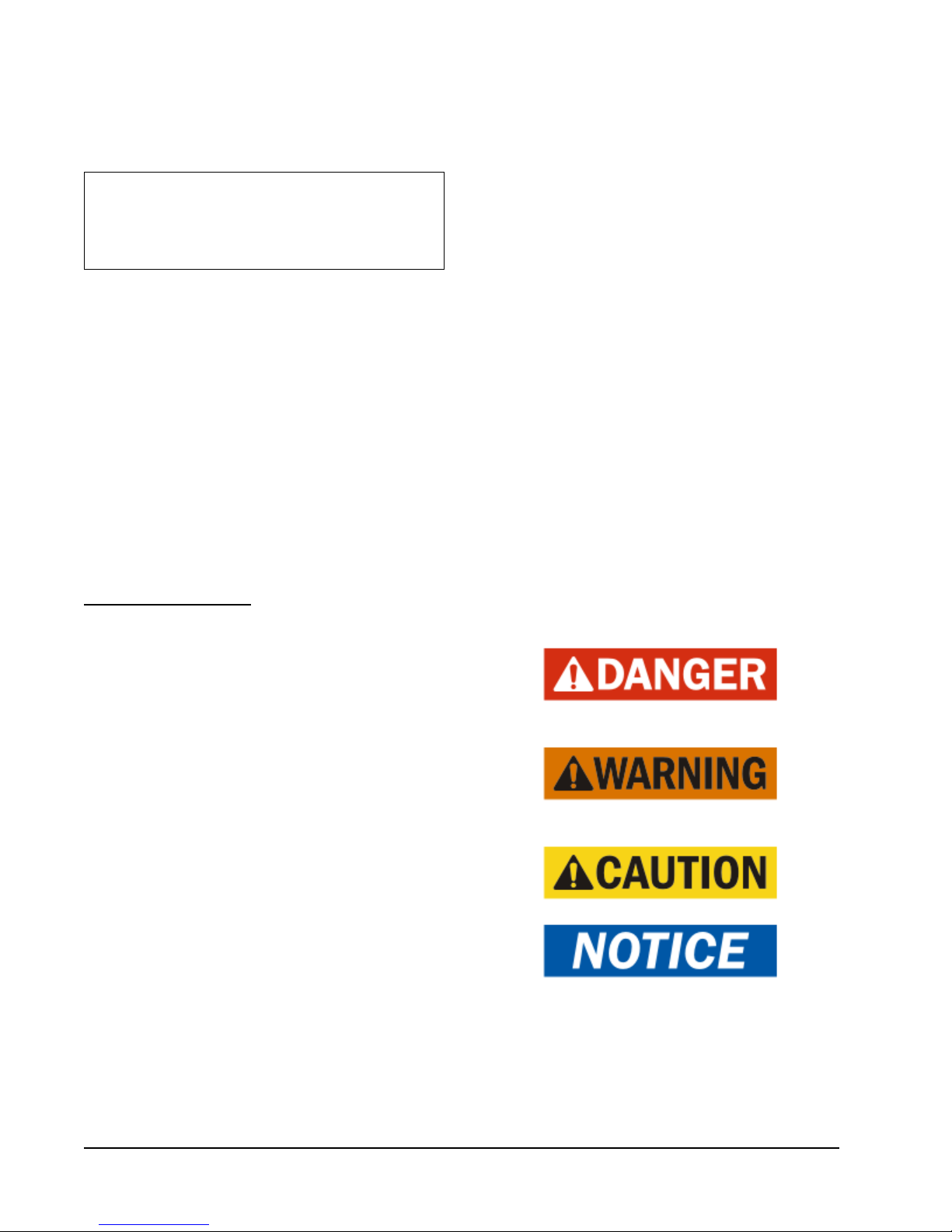
ANSI Z535.5 Denitions:
• Danger: Indicate[s] a hazardous situation which, if
not avoided, will result in death or serious injury. The
signal word “DANGER” is to be limited to the most
extreme situations. DANGER [signs] should not be used
for property damage hazards unless personal injury risk
appropriate to these levels is also involved.
• Warning: Indicate[s] a hazardous situation which,
if not avoided, could result in death or serious injury.
WARNING [signs] should not be used for property
damage hazards unless personal injury risk appropriate to
this level is also involved.
• Caution: Indicate[s] a hazardous situation which, if
not avoided, could result in minor or moderate injury.
CAUTION [signs] without a safety alert symbol may be
used to alert against unsafe practices that can result in
property damage only.
• Notice: [this header is] preferred to address practices
not related to personal injury. The safety alert symbol
shall not be used with this signal word. As an alternative
to “NOTICE” the word “CAUTION” without the safety
alert symbol may be used to indicate a message not
related to personal injury.
Manual 2100-578E
Page 4 of 41
I-TEC Series General Information
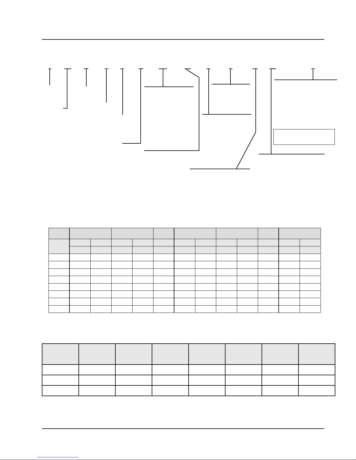
I-TEC MODEL NOMENCLATURE Z-Version (CA) 2-Stage Air Source Heat Pumps
I 36 Z 1 – A 0Z M P 1 X X 2
MODEL
SERIES
NOMINAL
CAPACITY
36 = 36,000 BTUH
48 = 48,000
60 = 60,000
SYSTEM TYPE:
H/P CA Design
REVISION
SPECIAL UNITS
(–) = Standard
C = 460V Circuit
Breaker
VOLTS & PHASE |
A = 230/208, 60-1
B = 230/208, 60-3
C = 460-60-3
ELECTRIC HEAT
0Z = No heat w/breaker
04 = 4KW 1-Phase
05 = 5KW 1-Phase
06 = 6KW 3-Phase
09 = 9KW 3-Phase
10 = 10KW 1-Phase
15 = 15KW 1 & 3-Phase
18 = 18KW 3-Phase
20 = 20KW 1-Phase
VENTILATION OPTIONS
B = Blank-Off Plate
M = Multi-Speed CRV
COLOR OPTIONS
X - Beige paint
1 - White paint
4 - Gray paint
FILTER OPTIONS
P = 2" Pleated MERV 8
M = 2" Pleated MERV 11
N = 2" Pleated MERV 13
VINYL GRAPHICS OPTIONS
X - None
A - Letter Assigned as Req'd.
CONTROLS
X = 24V Terminal Block Only w/o
CompleteStat
1 = CompleteStat THO (Temp,
Humidity & Occupancy)
2 = CompleteStat THO w/CO2
3 = CompleteStat THO w/Ethernet
4 = CompleteStat THO w/CO2 &
Ethernet
Note:CompleteStatmustbeeld
installed & wired. All units have
COIL TREATMENT
X - Std. Hydrophilic Fin Evap. &
Uncoated Alum. Cond. Coil
1 - Phenolic Coated ID Coil
2 - Phenolic Coated OD Coil
3 - Phenolic Coated ID & OD Coil
TABLE 1
FACTORY BUILT-IN ELECTRIC HEAT TABLE
Models I36Z1-A I36Z1-B I36Z1-C I48Z1-A
KW
10.0 34,130 25,598 34,130 25,598 34,130 25,598
15.0 51,195 38,396 51,195 38,396 51,195 51,195 38,396 51,195 38,396 51,195 51,195 38,396
18.0 61,434 46,076 61,434
20.0 68,260 51,195 68,260 51,195
240V-1 208V-1 240V-3 208V-3 460V-3 240V-1 208V-1 240V-3 208V-3 460V-3 240V-1 208V-1
BTUH BTUH BTUH BTUH BTUH BTUH BTUH BTUH BTUH BTUH BTUH BTUH
4.0 13,652 10,239
5.0 17,065 12,799 17,065 12,799 17,065 12,799
6.0 20,478 15,359 20,478 20,478 15,359 20,478
9.0 30,717 23,038 30,717 30,717 23,038 30,717
I48Z1-B
I60Z1-B
I48Z1-C
I60Z1-C
24V terminal block.
I60Z1-A
Model Rated ESP Max. ESP
I36Z1
I48Z1
I60Z1
.15 0.50 600 1150 850 700 1400
.20 0.50 725 1500 1050 700 1400
.20 0.50 850 1700 1200 700 1400
Motor will deliver consistent CFM through voltage supply range with no deterioration.
kContinuous fan CFM is the total air being circulated during continuous fan mode.
lWilloperateatratedFullLoadAirowwhenoperatingwithHeatPump.
mWill occur automatically with a call for "W3" or "Emergency Heat" signal from the thermostat (Heat Pump Operation is terminated at this condition).
TABLE 1A
INDOOR BLOWER PERFORMANCE
k
Continuous
CFM
Rated 2nd
Stage CFM
Rated 1st
Stage CFM
l
5 - 9 KW
CFM
13.5 - 18
KW CFM
Manual 2100-578E
Page 5 of 41
m

TABLE 2
ELECTRICAL SPECIFICATIONS
Single Circuit Multiple Circuit
Rated
MODEL
Volts,
Hertz &
Phase
I36Z1-A0Z
A05
230/208-1
A10
A15
I36Z1-B0Z
B06
230/208-3
B09
B15
I36Z1-C0Z
C06
460-3
C09
C15
I48Z1-A0Z
A04
A05
230/208-1
A10
A15
A20
I48Z1-B0Z
B06
230/208-3
B09
B15
B18
I48Z1-C0Z
C06
230/208-1
C09
C15
C18
I60Z1-A0Z
A05
230/208-1
A10
A15
A20
I60Z1-B0Z
B06
230/208-3
B09
B15
B18
I60Z1-C0Z
C06
460-3
C09
C15
C18
These“MinimumCircuitAmpacity”valuesaretobeusedforsizingtheeldpowerconductors.RefertotheNationalElectricCode(latestrevision),Article310forpowerconductorsizing.
Caution: Whenmorethanoneeldpowerconductorcircuitisrunthroughoneconduit,theconductorsmustbederated.Payspecialattentiontonote8oftable310regarding
Ampacity Adjustment Factors when more than three (3) current carrying conductors are in a raceway.
MaximumsizeofthetimedelayfuseorHVACtypecircuitbreakerforprotectionofeldwiringconductors.
Based on 75°C copper wire. All wiring must conform to the National Electrical Code and all local codes.
Maximum KW that can operate with the heat pump is 10KW for 1-Phase and 9KW for 3-Phase.
Represents Electric Heat only. Electric Control Circuit will lock-out Heat Pump Operation.
No.
Field
Power
Circuits
1
1
1 or 2
1 or 2
1
1
1
1
1
1
1
1
1
1
1 or 2
1 or 2
1 or 2
1 or 2
1
1
1
1
1
1
1
1
1
1
1
1 or 2
1 or 2
1 or 2
1 or 2
1
1
1
1
1 or 2
1
1
1
1
1
Minimum
Circuit
Ampacity
26
52
78
84
22
40
49
51
11
20
24
28
34
54
59
85
85
110
26
44
53
53
53
15
25
29
29
29
44
70
96
96
112
31
49
58
58
63
15
25
29
29
29
Maximum
External
Fuse or
Ckt. Brkr.
40
60
80
90
30
45
50
60
15
20
25
30
50
60
70
90
90
110
35
50
60
60
60
20
30
30
30
30
60
80
100
100
120
45
60
60
60
70
20
30
30
30
30
Field
Power
Wire
Size
8
6
4
4
10
8
8
6
14
12
10
10
8
6
6
3
3
2
8
8
6
6
6
12
10
10
10
10
8
4
3
3
2
8
8
6
6
6
12
10
10
10
10
Ground
Wire
10
10
10
10
10
10
14
12
10
10
10
10
10
10
10
10
10
12
10
10
10
10
10
10
10
10
10
12
10
10
10
10
Minimum
Circuit
Ampacity
Ckt. A Ckt. B Ckt. A Ckt. B Ckt. A Ckt. B Ckt. A Ckt. B
8
26265252404060
8
8
35
8
35
8
35
6
59
8
44
8
44
8
44
6
60
8 31 54 45 60 8 6 10 10
26
52
52
52
26
52
52
52
Maximum
External
Fuse or Ckt.
Breaker
60
45
30
45
60
45
60
60
60
60
30
60
60
60
60
60
60
Field Power
Wire Size
8
6
8
6
8
10
8
6
8
6
6
6
8
10
8
6
8
6
6
6
Ground Wire
Size
101010
10
10
10
10
10
10
10
10
10
10
10
10
10
10
10
10
10
Manual 2100-578E
Page 6 of 41
Back View
Air
Supply
Sleeve
Outer
Inner
Sleeve
Air
Return
RUBBER MATT
PART #5451-027
MIS-3114 A
WIRE TIES
PART #7950-031
"
3
4
1
(2) Opt.
Unit Drain
Entrances
"
4
3
1
Unit Specification Sheet
"
3
8
31
FIGURE 1 — UNIT DIMENSIONS
20" x 24" Supply Frame
"
7
26
Total Depth
8
Right Side View
High Voltage
Entrance
"
4
3
18
2"
Sides Removed
30" With Doors and
Wire Channel
Electric Heat
Outer
Sleeve
Openings
(2) Return
Hinges
(4) Lift-Off
Inner
Sleeve
94"
Locking
Door Latch
Return
Electrical
Disconnect
Air
" 50
1
4
"
3
4
71
Upper
Section
(2) Side
Handles
Drains
(2) Unit
58"
Door Latch
Locking
8"
"
8
1
22
"
1
2
24
"
1
4
22
Lower
Section
" 15
5
8
RUBBER MATT &
FRONT TRIM LOCATION
"
3
4
3
(Remove Sides)
Side Forklift Holes
Front Forklift Holes
(Remove Front Trim)
2
20" 18"
61 " Total Width
" With Sides Removed
1
8
46
"
1
4
3
Top View
24"
"
4
1
28
Entrance
Low Voltage
"
1
4
9
Front View
Filters
Return Air
(2) 2"x24"x30"
Control Panel
Air Filters
(2) 16" x 25"
Vent Exhaust
Manual 2100-578E
Page 7 of 41
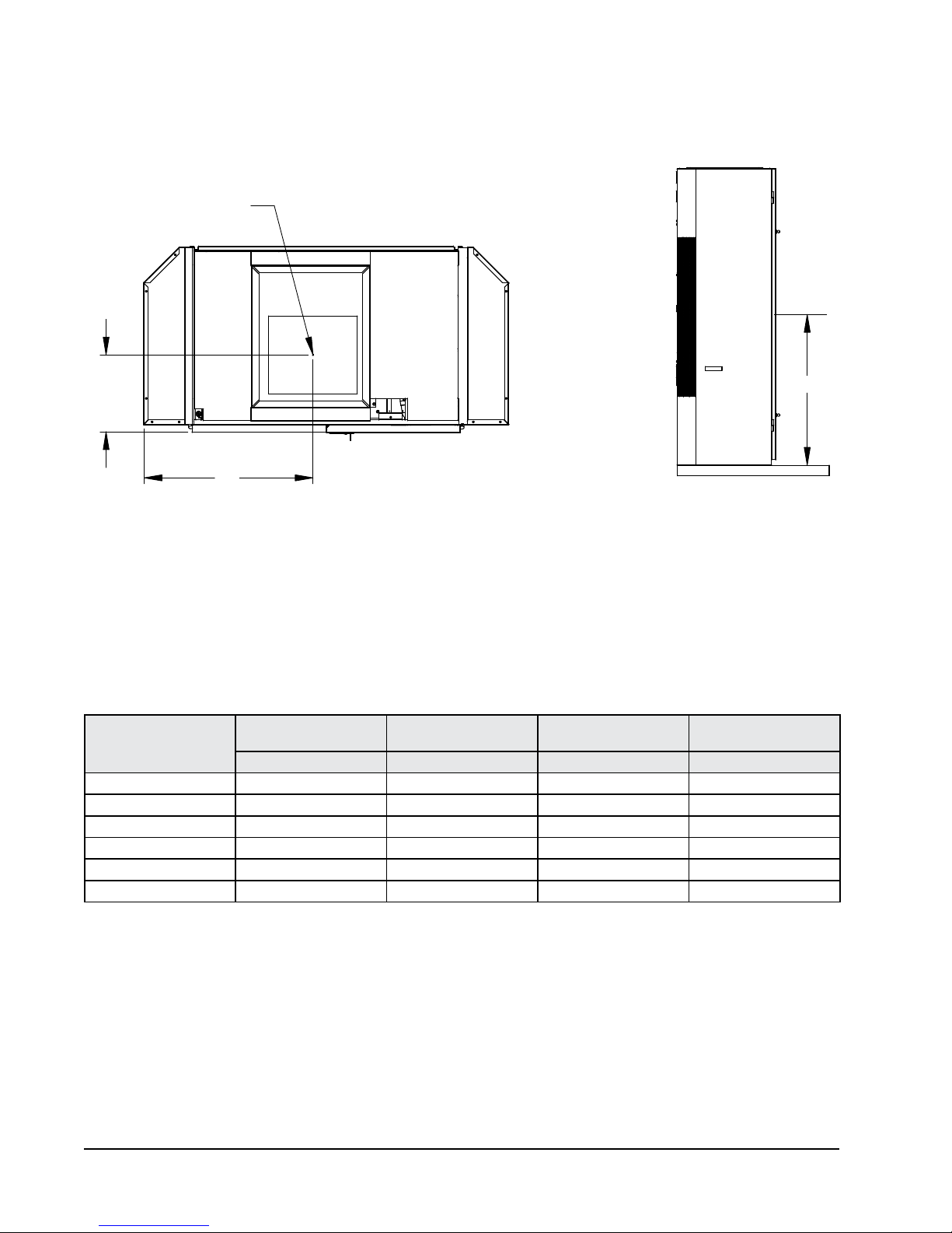
CENTER OF GRAVITY
CENTER OF GRAVITY
"X"
"Y"
FRONT OF UNIT
Unit Tested
I36Z1-A, B 13½" 31" 43½" 47"
I36Z1-C 13½" 31½" 43½" 47"
I48Z1-A, B 13½" 31" 43½" 47"
I48Z1-C 13½" 31½" 43½" 47"
I60Z1-A, B 13½" 31" 43½" 47"
I60Z1-C 13½" 31½" 43½" 47"
DOOR TO CENTER
"X" Dimension "Y" Dimension "Z" Dimension "Z" Dimension
LEFT SIDE
TO CENTER
FLOOR TO CENTER
CRV & ERV
FLOOR TO CENTER
NO VENT
"Z"
MIS-3268
Manual 2100-578E
Page 8 of 41
SHIPPING DAMAGE
Upon receipt of equipment, the unit should be checked
for external signs of shipping damage. The skid must
remain attached until the unit is ready for installation.
If damage is found, the receiving party must contact
the last carrier immediately, preferably in writing,
requesting inspection by the carrier’s agent.
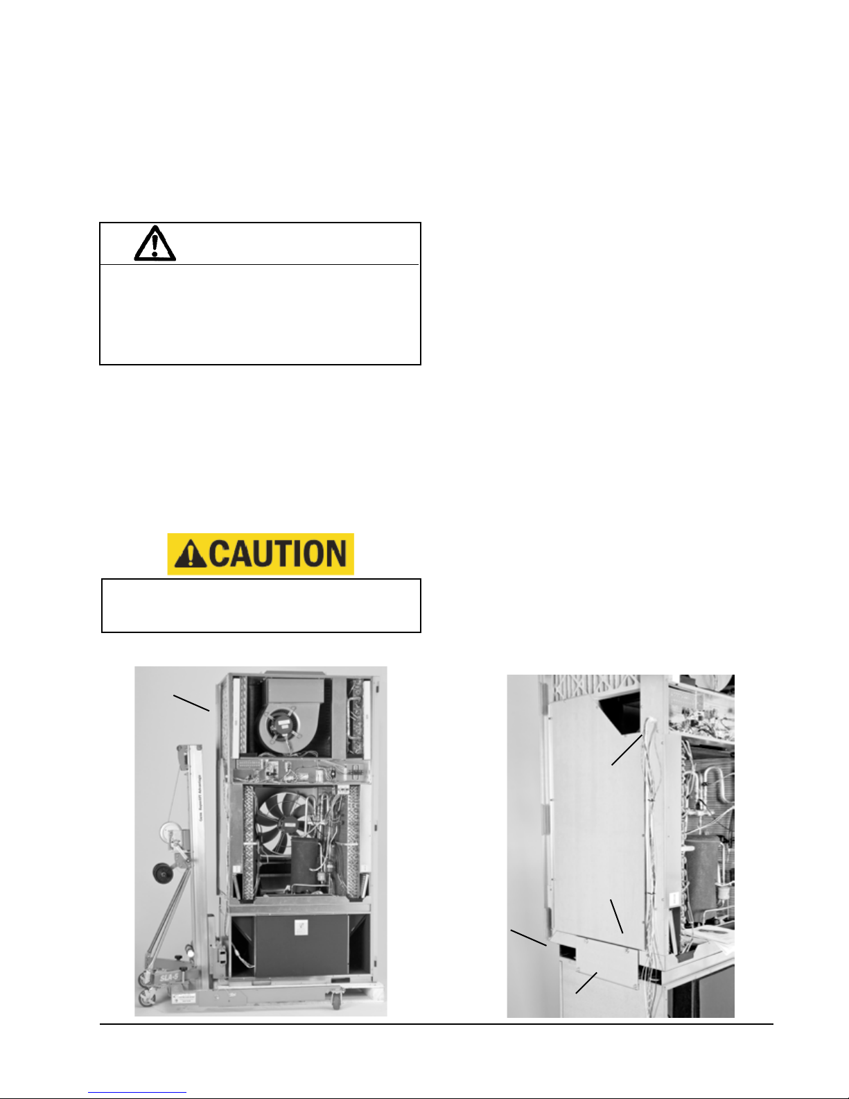
UNIT REMOVAL FROM SKID
WARNING
This unit is heavy and requires more than one person
to handle during installation and removal from the
skid. Extreme caution must be taken to prevent injury
to personnel and damage to the unit. Use appropriate
safety equipment, including gloves when handling.
Failure to do so may result in serious injury.
A forklift or a lift rated for the load (Figure 2A) is
required to lift the unit off from the skid. This unit is
top heavy and should never be tipped while moving it.
The I-TEC is designed to be lifted off the skid from the
front or rear of the unit without having to remove any
doors or side panels. See Figure 1 for fork openings.
The shipping brackets on front and rear of the unit must
be removed and discarded. The unit can now be lifted
straight up and the skid can be slid out from underneath.
Tip unit from left side only.
Failure to do so may result in injury due to unit
top-heaviness or compressor damage!
HANDLING UNIT AFTER REMOVAL FROM SKID
If a wide and tall opening exists, the I-TEC can be moved as a
complete assembled unit. If not, use the following directions for
dis-assembly to allow it to pass through a 36" wide door.
1. Depress and release both top & bottom door latches and
open doors.
2. Remove doors by lifting straight up & off from the hinge pins.
3. Remove cabinet sides by rst removing the four (4) sheet metal
screws from the front (leading edge) of the side panel. The panel
will not fall off. Swing the panel away from the chassis 20-30
degrees & then pull forward from the two (2) tabs supporting
the rear edge. At this point, the unit can be tipped on its left
side enough to get dolly carts under it. Use dolly carts to
move unit into installation area. Use care not to damage
vent wire harness. This method is not suggested due to unit
weight and if a forklift or unit lift is available, continue with
the following steps for separation of top section & bottom base.
4. On each side of the unit is a tie plate that secures the top &
bottom sections with four (4) cap bolts. Using a ½" wrench
or socket, remove these screws from both plates & set aside.
5. If the unit is equipped with a CRV, you must unplug the
wire harness on the left-hand side of the control box.
6. A forklift or a lift rated for the load is required to lift the
top section off from the bottom base. Do not attempt to
do this manually! Failure to do so could result in the
unit tipping over & causing bodily injury &/or damage to
the unit.
7. The top section can be forked from either the RH or LH
side. See Figure 1 for fork openings.
8. Carefully lift the top section straight up avoiding tipping.
9. Move the top section through the doorway & place on at
surface free of debris.
10. The bottom base can now be moved through the doorway
the same way.
11. Reassemble the unit by reversing this procedure.
FIGURE 2A UNIT ON LIFT
LEFT
SIDE
of
UNIT
FIGURE 2B UNIT SIDE
CRV
(4) CAP BOLTS
FORK OPENING
(Visible after
removing tie plate)
HARNESS CONNECTION
(Covers entire width; shortened for illustration
purposes to show Fork Openings)
TIE PLATE
Manual 2100-578E
Page 9 of 41
REQUIRED STEPS AFTER FINAL PLACEMENT
MIS-3029
2"
1 11/16"
43 3/8"
Ø1/4"
94" FROM BOTTOM
OF BRACKET TO
FLOOR WITHOUT
RISER KIT
7/8"
3/4"
1 1/2"
BRACKET
The compressor is secured to the base with two (2) bolts
for shipping. Although the unit will perform as designed
with the shipping bolts in place, there may be noticeable
additional noise and vibration noted. To obtain the lowest
noise and vibration levels, remove the shipping bolts after
the unit is in its nal operating location. To gain access
to the compressor, the compressor access panel must be
removed (Figure 7). Once this panel is removed, the CRV
air duct must be removed. See Figure 4.
The air duct is removed by pulling it straight toward you;
there are no screws securing it in place. Both the top and
bottom slide toward you at the same time (pull hard).
Once removed, the compressor is visible as well as the
tags on the shipping bolts (Figure 3).
After the compressor shipping bolts have been removed,
the CRV air duct can be slid back in place and the
compressor access panel attached.
MINIMUM INSTALLATION CLEARANCES
The minimum installation height to the bottom of the
roof or xed ceiling for ducted applications is 9 ft. 7 in.
This provides enough clearance to install the duct work.
See Figure 5A.
The IWS Series wall sleeve has a built-in vertical
adjustment to t window sill heights from 31-34 inches.
If additional height is required, two riser platform
accessories are available. The IRZ3 increases the
unit height by 3 inches (Figure 5B) and the IRZ6 by 6
inches (Figure 5C).
Several construction options are available for unit
installation of the IZ Series. Serviceability and lter
access must be considered before installing. See Figure
5D for required clearances and recommended service
access dimensions.
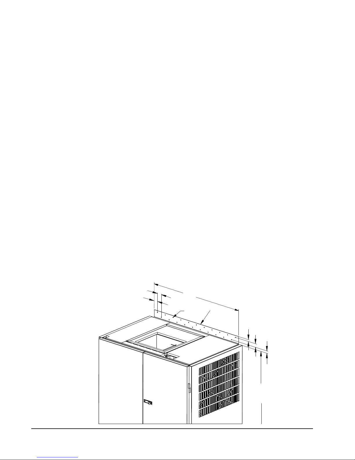
SECURING UNIT TO STRUCTURE
Shipped with the I-TEC unit is a wall mounting bracket
(screwed to shipping skid on backside of unit). This bracket
can be utilized to secure the top portion of the unit to the
wall using the appropriate eld supplied hardware based
upon the material you are fastening to. (There are several
offset holes, sized to accept up to a 1/4" diameter fastener
that will easily allow you to hit studs on a framed wall.) See
BRACKET SECTION VIEW (Page 10) for locating this top
wall bracket which will need to be applied after the unit is
located in the nal position.
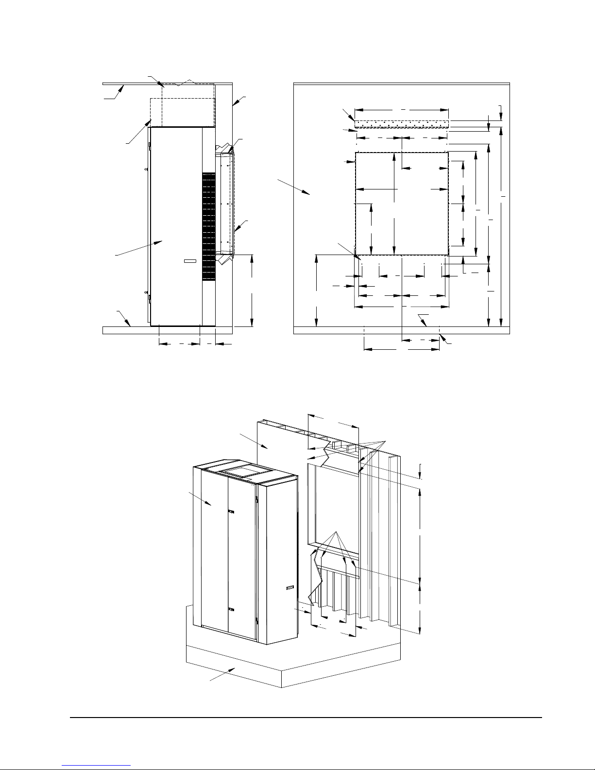
Additional/optional mounting holes for up to a 3/8"
diameter fastener are also available in the backside and
base of the unit. These can be accessed by:
• removing the air lters (uppermost set)
• removing the compressor section service door (lower set)
• removing vent door and vent partitions (base set)
Refer to WOOD FRAMED INSTALLATION (Page 10) for
additional framing required to secure unit to wall.
The additional/optional mounting holes will require a
long extension to drive the fasteners.
SEISMIC CONSIDERATIONS
The I-TEC product features several locations for product
securement but all site conditions are different. Consult
with a licensed Seismic Engineer to advise of particular
needs when attaching the I-TEC unit to the structure.
RUBBER MAT
Unit rests on rubber mat placed under base rails during
installation. Place mat on oor ush with wall and
centered over wall opening.
WALL MOUNTING
BRACKET LOCATION
Manual 2100-578E
Page 10 of 41
35"
17
1
2
"
"
3
4
18 7
3
8
"
(4) optional Unit
Mounting holes
C
L
C
L
Mounting holes
(4) optional Unit
Bracket
*
** Separate telescoping sleeves available for different wall thicknesses.
Centered on
Optional Top
*
* Higher Sill Heights Acheivable With Base Kit.
Opening
Wall
Room Floor Level
Outside
Sleeve Mounting
Hole Locations
FLOOR MOUNTING HOLE
& CENTERLINES
8
20
7
6"
8
20 "
2
32
1
7
"
"29
"
17
8"
56
8"
20
7
8
"
8
""94
1
31" Min.
20"
34" Max.
3"
1
48-1/2" Max.
48" Min.
3
Centered
8
Centered
43-1/4" Max.
"
49
16
8
"
20"
20"
20"
43
7
42-3/4" Min.
"
16
11
15
4
43
3
8
"
Duct
Grille
Floor
Optional
Outside
Ceiling
Wall Sleeve**
Telescoping
Wall
Unit
Optional
Trim or
Supply Duct
Box
31" Min.
34" Max.
C
L
Wall Section View
Right Side View
Front (Wall Only) View
C
L
MIS-3196 A
6.00
41.75
56.50
29.568.00
8.0036.88
20.88
MIS-3197
(4) lower fastener
holes
Floor
riser kit. If unit uses riser kit add
appropriate dimension to height.
Inner wall
Unit
*
(4) Upper
fastener holes
* Height dimension shown without
BRACKET WALL SECTION VIEW
WOOD FRAMED INSTALLATION (for Wall Attachment)
Manual 2100-578E
Page 11 of 41
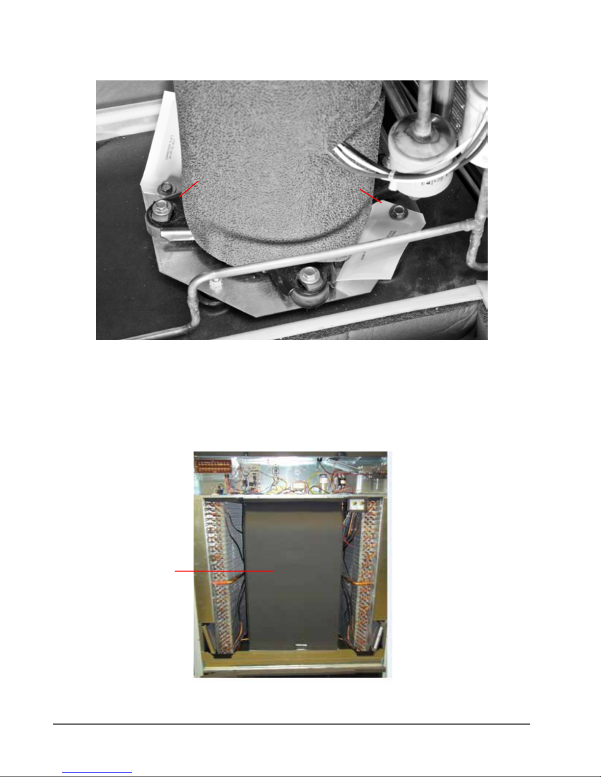
COMPRESSOR SHIPPING BOLTS
COMPRESSOR
SHIPPING BOLT
FIGURE 3
COMPRESSOR
SHIPPING BOLT
CRV
AIR DUCT
FIGURE 4
REMOVAL OF AIR DUCT
Manual 2100-578E
Page 12 of 41
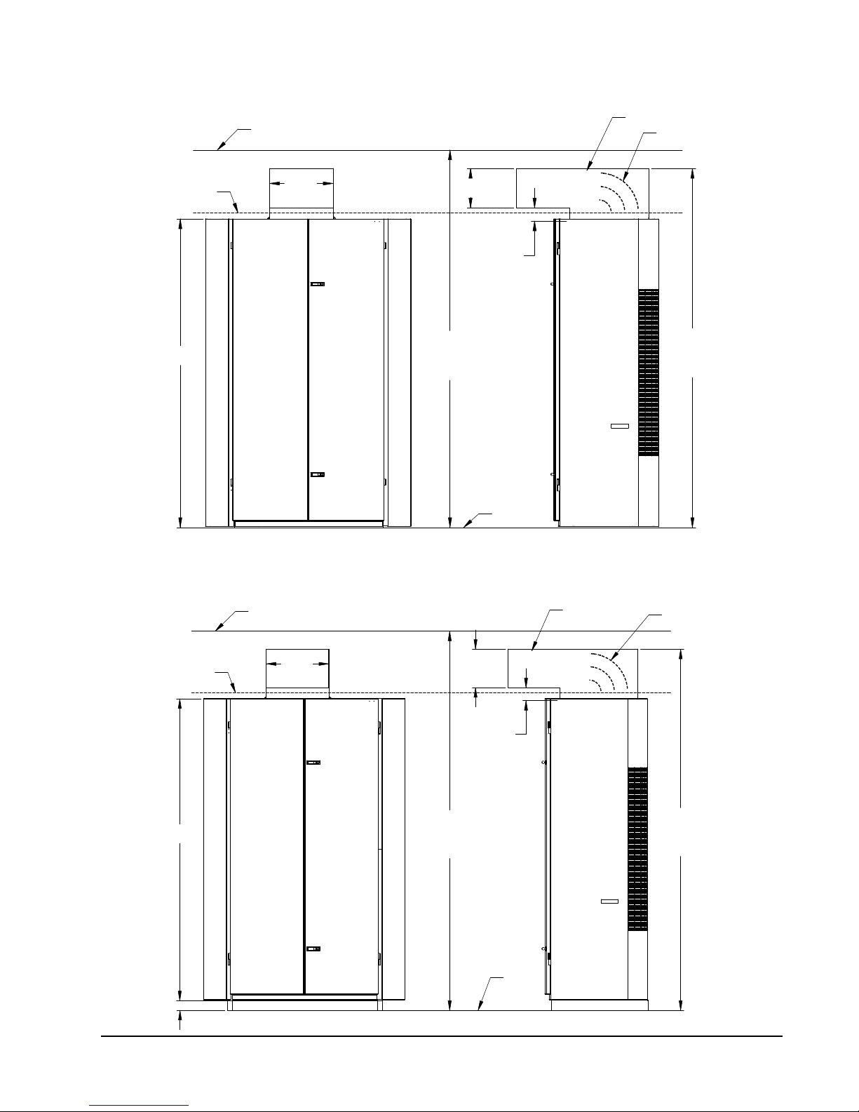
INSTALLATION
9'-5"
MINIMUM
REQUIRED
HEIGHT
9'-10" MINIMUM
CLEARANCE
RECOMMENDED TO
BOTTOM OF ROOF
OR FIXED CEILING
3" RISER
FIELD SUPPLIED DUCT
MIS-3199
TURNING VANES
RECOMMENDED
MINIMUM
12"
4" MINIMUM FROM
TOP OF UNIT TO
DUCT BOTTOM
BOTTOM OF ROOF
FLOOR
OR FIXED CEILING
SUSPENDED
CEILING
20"
MINIMUM
7'-9 3/4"
UNIT HEIGHT
9'-7" MINIMUM
CLEARANCE
RECOMMENDED TO
BOTTOM OF ROOF
OR FIXED CEILING
9'-2"
MINIMUM
REQUIRED
INSTALLATION
HEIGHT
BOTTOM OF ROOF
FLOOR
OR FIXED CEILING
SUSPENDED
CEILING
20"
MINIMUM
7'-9 3/4"
UNIT HEIGHT
FIELD SUPPLIED DUCT
MIS-3198
TURNING VANES
RECOMMENDED
MINIMUM
12"
4" MINIMUM FROM
TOP OF UNIT TO
DUCT BOTTOM
FIGURE 5A
DUCTED APPLICATION – BASIC UNIT
FIGURE 5B
3" RISER APPLICATION
Manual 2100-578E
Page 13 of 41
 Loading...