

Bard HA4S4KA, HA5S4KA, HL4S4KA, HL5S4KA Installation Instructions Manual
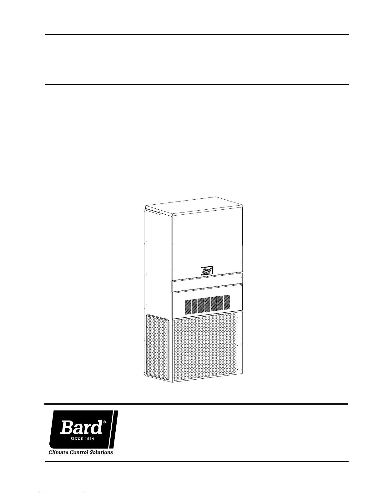
INSTALLATION INSTRUCTIONS
WALL-MOUNTED
PACKAGED AIR CONDITIONER
Models:
HA4S4KA
HA5S4KA
HL4S4KA
HL5S4KA
Bard Manufacturing Company, Inc.
Bryan, Ohio 43506
www.bardhvac.com
MIS-2498
Manual: 2100-646
Supersedes: NEW
Date: 9-3-15
Page 1 of 26

CONTENTS
Getting Other Information and Publications
Wall Mount General Information
Air Conditioner Wall Mount Model Nomenclature
Shipping Damage
General
Duct Work
Filters
............................................................... 7
........................................................... 7
................................................................. 7
Condensate Drain
Installation
Wall Mounting Information
Mounting the Unit
Typical Installations
Wiring – Main Power
Wiring – Low V
................................................. 7
................................................ 7
............................................................... 8
.................................... 8
................................................ 8
.............................................. 8
............................................. 8
oltage Wiring ................................. 12
......................... 4
..... 4
Dirty Filter Switch and Relay ............................... 13
Economizer Fail Time Delay Relay ........................ 13
Figures
Figure 1 Unit Dimensions .................................. 5
Figure 2
Mounting Instructions .......................... 9
Figure 3 Wall Mounting Instructions ................. 10
Figure 4
Wall Mounting Instructions ................. 10
Figure 5 Common Wall Mounting Installations ... 11
Figure 6 Electric Heat Clearance ...................... 12
Figure 7 Start Up Label ................................... 17
Figure 8
Fan Blade Setting .............................. 18
Figure 9 Control Disassembly ........................... 21
Figure 10 Winding Test ...................................... 21
Figure 11 Drip Loop .......................................... 21
Figure 12 H***S4 Wiring Diagram – Top ............. 24
Figure 13
H***S4 Wiring Diagram – Bottom ........ 25
Figure 14 H***S4 Low Voltage Ladder Diagram
for Unit and MV Connections ............... 26
3
Start Up ................................................................... 14
General
Topping Off System Charge
Safety Practices
Important Installer Note
Service Hints
Sequence of Operation
High and Low Pressure Switch
Compressor Control Module
Motor Start Device
Pressure Service Ports
Crankcase Heaters
Service
Compressor Solenoid
Fan Blade Setting Dimensions
............................................................. 14
................................. 14
................................................. 14
...................................... 14
..................................................... 14
........................................ 15
............................. 15
................................. 15
.............................................. 16
........................................ 16
.............................................. 16
..................................................................... 18
.......................................... 18
............................. 18
Removal of Fan Shroud ....................................... 18
R-410A Refrigerant Charge ................................. 19
Troubleshooting GE ECM
TM
Motors ....................... 20
Optional Accessories ........................................... 21
Tables
Table 1 Electric Heat ....................................... 4
Table 2 Dimensions of Basic Unit ...................... 5
Table 3 Electrical Specifications ....................... 6
Table 4
Sequence of Operation ....................... 15
Table 5 Fan Blade Dimensions ........................ 18
Table 6 Cooling Pressure ................................ 19
Table 7 Indoor Blower Performance ................. 22
Table 8
Optional Accessories
Table 9 Optional Accessories
– RH Units .......... 22
– LH Units .............22
Manual 2100-646
Page 2 of 26

GETTING OTHER INFORMATION AND PUBLICATIONS
These publications can help when installing the
furnace. They can usually be found at the local library
or purchased directly from the publisher. Be sure to
consult the current edition of each standard.
National Electrical Code
Standard for the Installation of
Air Conditioning and Ventilating
Systems .......................................... ANSI/NFPA 90A
Standard for Warm Air Heating
and Air Conditioning Systems
Load Calculation for Residential
inter and Summer
W
Air Conditioning
Low Pressure, Low Velocity
Duct System Design for
inter and Summer
W
Air Conditioning
..............ACCA Manual J or Manual N
............. ACCA Manual D or Manual Q
...................... ANSI/NFPA 70
............ANSI/NFPA 90B
For more information, contact these publishers:
ACCA
Air Conditioning Contractors of America
1712 New Hampshire Ave. N.W.
Washington, DC 20009
Telephone: (202) 483-9370
Fax: (202) 234-4721
ANSI American National Standards Institute
New York, NY 10036
Telephone: (212) 642-4900
Fax: (212) 302-1286
ASHRAE American Society of Heating, Refrigeration
and Air Conditioning Engineers, Inc.
1791 Tullie Circle, N.E.
Atlanta, GA 30329-2305
Telephone: (404) 636-8400
Fax: (404) 321-5478
NFPA National Fire Protection Association
Batterymarch Park
P.O. Box 9101
Quincy, MA 02269-9901
Telephone: (800) 344-3555
Fax: (617) 984-7057
11 West Street, 13th Floor
Manual 2100-646
Page 3 of 26
WALL MOUNT GENERAL INFORMATION
AIR CONDITIONER WALL MOUNT MODEL NOMENCLATURE
HA 4S 4 K A 05 B P X X X J
MODEL NUMBER
HA – Right Hand
HL – Left Hand
CAPACITY
4S – 4 Ton
5S – 5 Ton
REVISION
K – Accumulator
VOLTS & PHASE
A – 230/208-1
– No KW
0Z
w/Circuit Breaker
or Pull Disconnect
05 – 5 KW
08 – 8 KW
10
– 10 KW
15 – 15 KW
KW
VENTILATION OPTIONS
B – Blank-Off Plate
(No Ventilation)
Y – 100% Economizer
(Temperature)
Z – 100% Economizer
(Enthalpy)
FILTER OPTIONS
P – 2" Pleated MERV 8
CONTROL MODULES
J – Only
COIL OPTIONS
X – Standard
1
–
Phenolic Coated
Evaporator
2
–
Phenolic Coated
OUTLET OPTIONS
X – Front (Standard)
COLOR OPTIONS
X – Beige (Standard)
4 – Buckeye Gray
5 – Desert Brown
8 – Dark Bronze
A – Aluminum
S – Stainless Steel
Condenser
3
–
Phenolic Coated
Evaporator and
Condenser
TABLE 1
Electric Heat Table
Nominal
KW
5.0 5.0 20.8 17,065 3.75 18.0 12,799
8.0 8.0 33.3 27,304 6.00 28.8 20,478
10.0 10.0 41.7 34,130 7.50 36.1 25,598
15.0 15.0 62.5 51,195 11.25 54.1 38,396
These electric heaters are available in 230/208V units only.
Kw 1-Ph Amps Btuh Kw 1-Ph Amps Btuh
At 240V At 208V
See Table 3 for heater availability by model
Manual 2100-646
Page 4 of 26
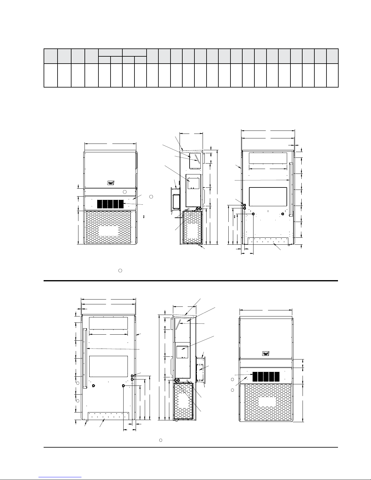
TABLE 2
1
Not used when EWM Economizer is installed. Filter access through the EWM hood
MIS-3761
Electrical
Entrances
Optional
Side Wall
Mounting
Brackets
(Built In)
Location
Shipping
Return Air Opening
Supply Air Opening
Top Rain
Flashing
Bottom Installation
Bracket
Back View
M
L
O
E
R
S1
S1
S1
S2
S2
T
.44
N
Q
P
B
Low Voltage
Electrical
Entrance
High Voltage
Electrical
Entrance
Economizer
Intake Hood
4° Pitch
(Lockable)
Rain Hood
Built In
Air
Inlet
Access
Panel
Cond.
Heater
Electric
Heat
C. Breaker/
Disconnect
Access Panel
Drain
Side View
C H
K
J
I
D
2.13
A
Vent Option
Door
1
1
Condenser
Filter Access Panel
Air Outlet
Ventilation
Air
Front View
F
G
W
5.75
Condenser
Air Outlet
I
A
C
K
2.13
H
J
N
Q
P
M
L
O
E
.44
W
5.88
F
G
R
S
S
S
S
S
T
D
B
1
High Voltage
Drain
Economizer
Inlet
Front View
Side View
1
Electrical
Cond.
Air
Back View
Door
Bottom
Installation
Bracket
Side Wall
Mounting
Brackets
Flashing
Shipping
Location
Optional
Electrical
Entrances
Panel
Air
Ventilation
Electrical
Entrance
MIS-3762
Intake Hood
Entrance
(Built In)
Top Rain
Low Voltage
Filter Access Panel
Access Panel
(Lockable)
Vent Option
Disconnect
Electric
Heat
Heater
Access
Return Air Opening
1
Rain Hood
4° Pitch
1
Supply Air Opening
C. Breaker/
Built In
Economizer Controls
Opposite Side
1
Not used when EWM economizer is installed. Filter access through the EWM hood.
Dimensions of Basic Unit for Architectural and Installation Requirements (Nominal)
WidthWDepthDHeight
Unit
HA4S4
HL4S4
42.075 22.432 94.875 9.88 29.88 15.88 29.88 43.88 19.10 41.66 30.00 42.68 36.94 44.69 42.43 3.37 43.00 33.88 10.00 1.44 16.00 21.00 1.88
HA5S4
HL5S4
All dimensions in inches. Dimensional drawings are not to scale.
Supply Return
H
E F G I J K L M N O P Q R S1 S2 TA B C B
FIGURE 1
Unit Dimensions
HA*S4
RIGHT
UNIT
HL*S4
LEFT
UNIT
Manual 2100-646
Page 5 of 26
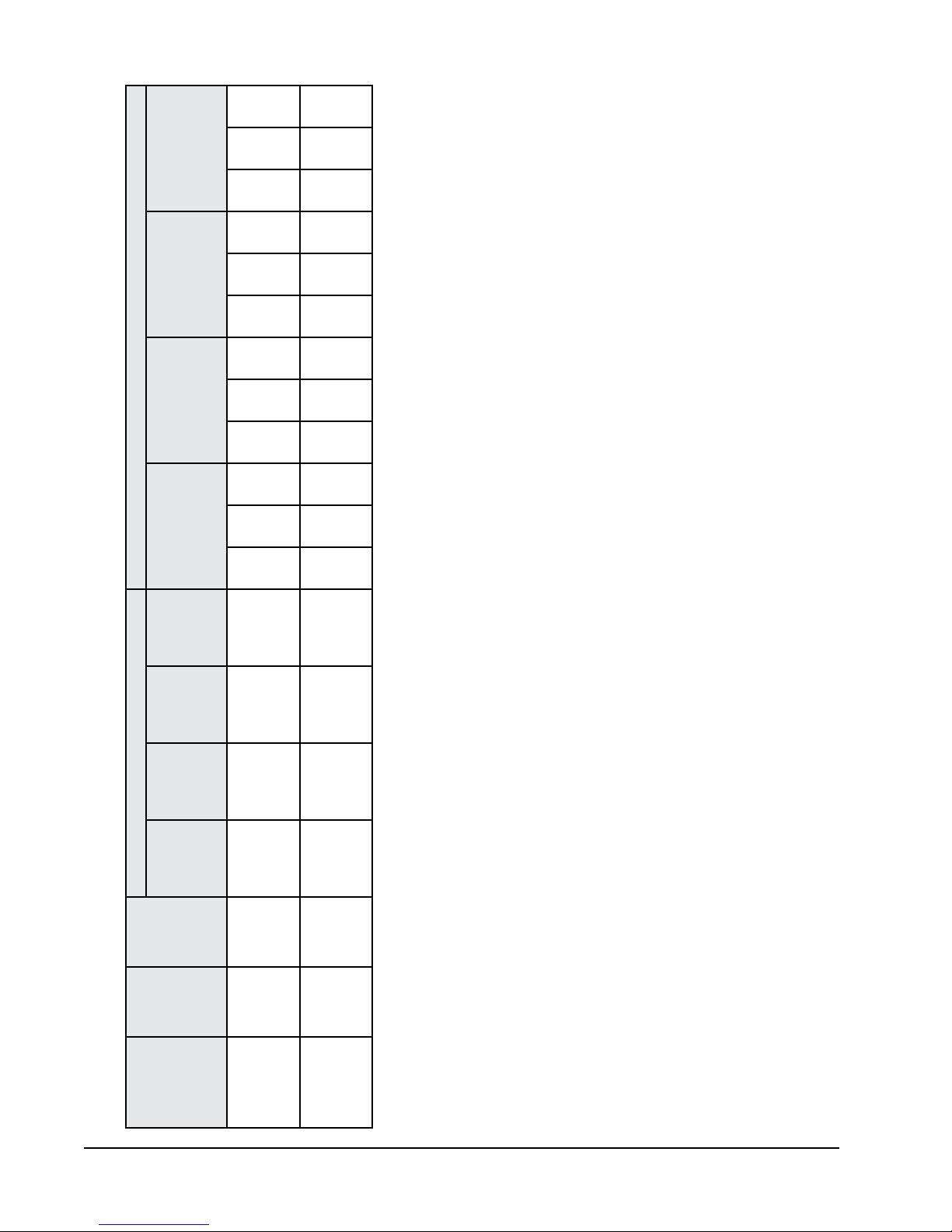
Wire
Ground
10
10
10
10
10
10
10
10
Field
Power
Wire Size
Maximum
or Ckt. Brkr.
External Fuse
Circuit
Ampacity
Minimum
Ckt. A Ckt. B Ckt. C Ckt. A Ckt. B Ckt. C Ckt. A Ckt. B Ckt. C Ckt. A Ckt. B Ckt. C
TABLE 3
Wire
Ground
Electrical Specifications
Field
Power
Wire Size
10
8
30
45
26
37
8
101010
88643
6
8
60
45
52
37
8
101010
88663
10
8
30
50
26
44
8
6
8
60
50
52
44
8
Single Circuit Multiple Circuit
Maximum
or Ckt. Brkr.
External Fuse
Circuit
Ampacity
Minimum
Power
Circuits
No. Field
Volts
Rated
and Phase
Model
4545607090
3838536389
111
1 or 2
1 or 2
230/208-1
- A05
- A08
- A10
HA/L4S4 - A0Z
- A15
5050607090
4444536389
111
HA/L5S4 - A0Z
Manual 2100-646
Page 6 of 26
1 or 2
1 or 2
230/208-1
- A05
- A08
- A10
- A15
CAUTION: When more than one filed power conductor circuit is run through one conduit, the conductors must be derated.
conductor sizing.
Pay special attention to Note * of Table 310 regarding Ampacity Adjustment Factors when more than three conductors are in a raceway.
These “Minimum Circuit Ampacity” values are to be used for sizing the field power conductors. Refer to the National Electric Code (latest version), Article 310 for power
Based on 75°C copper wire. All wiring must conform to the National Electric Code (NEC) and all local codes.
Maximum size of the time delay fuse or circuit breaker for protection of field wiring conductors.
SHIPPING DAMAGE
Upon receipt of equipment, the carton should be
checked for external signs of shipping damage. If
damage is found, the receiving party must contact
the last carrier immediately, preferably in writing,
requesting inspection by the carrier’s agent.
GENERAL
The equipment covered in this manual is to be installed
by trained, experienced service and installation
technicians.
The refrigerant system is completely assembled and
charged. All internal wiring is complete.
The unit is designed for use with or without duct work.
Flanges are provided for attaching the supply and
return ducts.
These instructions explain the recommended method
to install the air cooled self-contained unit and the
electrical wiring connections to the unit.
These instructions and any instructions packaged with
any separate equipment required to make up the entire
air conditioning system should be carefully read before
beginning the installation. Note particularly “Starting
Procedure” and any tags and/or labels attached to the
equipment.
While these instructions are intended as a general
recommended guide, they do not supersede any
national and/or local codes in any way. Authorities
having jurisdiction should be consulted before the
installation is made. See page 3 for information on
codes and standards.
Size of unit for a proposed installation should be based
on heat loss calculation made according to methods of
Air Conditioning Contractors of America (ACCA). The
air duct should be installed in accordance with the
Standards of the National Fire Protection Association
for the Installation of Air Conditioning and Ventilating
Systems of Other Than Residence Type, NFPA No.
90A, and Residence Type Warm Air Heating and Air
Conditioning Systems, NFPA No. 90B. Where local
regulations are at a variance with instructions, installer
should adhere to local codes.
DUCT WORK
All duct work, supply and return, must be properly
sized for the design airflow requirement of the
equipment. Air Conditioning Contractors of America
(ACCA) is an excellent guide to proper sizing. All duct
work or portions thereof not in the conditioned space
should be properly insulated in order to both conserve
energy and prevent condensation or moisture damage.
Refer to Table 7 for maximum static pressure available
for duct design.
Design the duct work according to methods given by
the Air Conditioning Contractors of America (ACCA).
When duct runs through unheated spaces, it should
be insulated with a minimum of 1" of insulation. Use
insulation with a vapor barrier on the outside of the
insulation. Flexible joints should be used to connect
the duct work to the equipment in order to keep the
noise transmission to a minimum.
A 1/4" clearance to combustible material for the first
3' of duct attached to the outlet air frame is required.
See Wall Mounting Instructions and Figures 3 and 4 for
further details.
Ducts through the walls must be insulated and all joints
taped or sealed to prevent air or moisture entering the
wall cavity.
!
CAUTION
Some installations may not require any
return air duct. A return air grille is
required with installations not requiring
a return air duct. The spacing between
louvers on the grille shall not be larger
than 5/8".
Any grille that meets the 5/8" louver criteria, may be
used. It is recommended that Bard Return Air Grille
Kit RG-5 or RFG-5 be installed when no return duct
is used. Contact distributor or factory for ordering
information. If using a return air filter grille, filters
must be of sufficient size to allow a maximum velocity
of 400 fpm.
NOTE:
If no return air duct is used, applicable
installation codes may limit this cabinet to
installation only in a single story structure.
FILTERS
A 2" pleated MERV 8 filter is supplied with each unit.
The filter slides into position making it easy to service.
This filter can be serviced from the outside by removing
the filter access panel.
CONDENSATE DRAIN
A plastic drain hose extends from the drain pan at
the top of the unit down to the unit base. There are
openings in the unit base for the drain hose to pass
through. In the event the drain hose is connected to
a drain system of some type, it must be an open or
vented type system to assure proper drainage.
Manual 2100-646
Page 7 of 26
INSTALLATION
WALL MOUNTING INFORMATION
1. Two holes, for the supply and return air openings,
must be cut through the wall as shown in Figure 3.
On wood-frame walls, the wall construction must
2.
be strong and rigid enough to carry the weight of
the unit without transmitting any unit vibration.
See Figures 4 and 5.
3. Concrete block walls must be thoroughly inspected
to insure that they are capable of carrying the
weight of the installing unit.
MOUNTING THE UNIT
1. These units are secured by wall mounting brackets
which secure the unit to the outside wall surface at
both sides. A bottom mounting bracket is provided
for ease of installation.
2.
The unit itself is suitable for 0 clearance, but the
supply air duct flange and the first 3’ of supply
air duct require a minimum of 1/4” clearance to
combustible material. If a combustible wall, use
a minimum of 30-1/2” x 10-1/2” dimensions for
sizing. However, it is generally recommended that
a 1” clearance is used for ease of installation and
maintaining the required clearance to combustible
material. The supply air opening would then be
32” x 12”. See
Figures 2, 3 and 6 for details.
3. Locate and mark lag bolt locations and bottom
mounting bracket location (see Figure 4).
Mount bottom mounting bracket.
4.
5. Hook top rain flashing under back bend of top.
Top rain flashing is shipped secured to the right
side of the back.
6.
Position unit in opening and secure with 5/16"
lag bolts; use 7/8" diameter flat washers on the
lag bolts.
Secure rain flashing to wall and caulk across
7.
entire length of top (see Figure 2).
8.
For additional mounting rigidity, the return air
and supply air frames or collars can be drilled
and screwed or welded to the structural wall itself
(depending upon wall construction). Be sure to
observe required clearance if combustible wall.
9. On side-by-side installations, maintain a
minimum of 20" clearance on right side to
allow access to heat strips and control panel
and to allow proper airflow to the outdoor coil.
Additional clearance may be required to meet
local or national codes.
TYPICAL INSTALLATIONS
See Figure 5 for common ways to install the wall
mount unit.
!
WARNING
Failure to provide the 1/4" clearance
between the supply duct and a combustible
surface for the rst 3' of duct can result in
re causing damage, injury or death.
Clearances Required for Service Access
and Adequate Condenser Airflow
MODELS
HA4S4, HL4S4
HA5S4, HL5S4
NOTE: For side-by-side installation of two H**S4 models, there
must be 20" between units. This can be reduced to 15"
by using a HL*S4 model (left side compressor and controls) for the left unit and HA*S4 (right side compressor
and controls) for right unit.
See H**S4 Specification S3458.
LEFT
SIDE
20" 20" 10”
RIGHT
SIDE
DISCHARGE
SIDE
WIRING – MAIN POWER
Refer to the unit rating plate for wire sizing
information and maximum fuse or circuit breaker
size. Each outdoor unit is marked with a “Minimum
Circuit Ampacity”. This means that the field wiring
used must be sized to carry that amount of current.
Depending on the installed KW of electric heat, there
may be two field power circuits required. If this is the
case, the unit serial plate will so indicate. All models
are suitable only for connection with copper wire.
Each unit and/or wiring diagram will be marked “Use
Copper Conductors Only”. These instructions must
be adhered to. Refer to the National Electrical Code
(NEC) for complete current carrying capacity data on
the various insulation grades of wiring material. All
wiring must conform to NEC and all local codes.
The electrical data lists fuse and wire sizes (75ºC
copper) for all models, including the most commonly
used heater sizes. Also shown are the number of field
power circuits required for the various models with
heaters.
Manual 2100-646
Page 8 of 26
 Loading...