

Page 1
INSTALLATION
INSTRUCTIONS
WALL MOUNTED
PACKAGED
AIR CONDITIONER
Models:
HA4S3 HL4S2
HA5S3 HL5S2
Bard Manufacturing Company, Inc.
Bryan, Ohio 43506
Since 1914...Moving ahead just as planned.
0,6
Manual : 2100-573A
Supersedes: 2100-573
File: Volume III Tab 16
Date: 07-09-12
Manual 2100-573A
Page 1 of 21
Page 2

CONTENTS
Getting Other Information and Publications
For more information contact these publishers........ 3
Wall Mount General Information
Air Conditioner Wall Mount Model Nomenclature.... 4
Shipping Damage .................................................... 7
General ............................................................... 7
Duct Work ............................................................... 7
Filters ............................................................... 7
Condensate Drain.................................................... 7
Installation Instructions
Wall Mounting Information....................................... 8
Mounting the Unit .................................................... 8
Typical Installations ................................................. 8
Wiring – Main Power ................................8 - 9 & 12
Wiring – Low Voltage Wiring ............................... 12
Dirty Filter Switch & Relay ..................................... 12
Figures
Figure 1 Unit Dimensions..................................... 5
Figure 2 Mounting Instructions............................. 9
Figure 3 Wall-Mounting Instructions .................. 10
Figure 4 Wall-Mounting Instructions .................. 10
Figure 5 Common Wall-Mounting Instructions ....11
Figure 6 Electric Heat Clearance ....................... 12
Figure 7 Start-Up Label...................................... 14
Figure 8 Fan Blade Setting ................................ 17
Figure 9 Control Disassembly ............................ 20
Figure 10 Winding Test ........................................ 20
Figure 11 Drip Loop ............................................. 20
Start Up
General ............................................................. 13
Topping Off System Charge................................... 13
Safety Practices..................................................... 13
Important Installer Note ......................................... 14
Crankcase Heaters................................................ 14
High & Low Pressure Switch ................................. 14
Service Hints ......................................................... 15
Compressor Control Module.................................. 15
Adjustments........................................................... 16
Motor Start Device ................................................. 16
Pressure Service Ports.......................................... 16
Troubleshooting
Compressor Solenoid ............................................ 17
Fan Blade Setting Dimensions .............................. 17
Removal of Fan Shroud......................................... 17
R-410A Refrigerant Charge ................................... 18
Pressure Chart ...................................................... 18
GE ECM™ Motors.................................................. 19
GE ECM™ Motors.................................................. 20
Optional Accessories ............................................. 21
Tables
Table 1 Electric Heat Table................................. 4
Table 2 Dimensions of Basic Unit....................... 5
Table 3 Electrical Specifications ......................... 6
Table 4 Fan Blade Dimensions......................... 17
Table 5 Cooling Pressure ................................. 18
Table 6 Indoor Blower Performance ................. 21
Table 7 Opt. Accessories (HA) ......................... 21
Table 8 Opt. Accessories (HL).......................... 21
Manual 2100-573A
Page 2 of 21
Page 3

Getting Other Information and Publications
These publications can help you install the air conditioner
or heat pump. You can usually find these at your local
library or purchase them directly from the publisher. Be
sure to consult current edition of each standard.
National Electrical Code ...................... ANSI/NFPA 70
Standard for the Installation...............ANSI/NFPA 90A
of Air Conditioning and
Ventilating Systems
Standard for Warm Air ...................... ANSI/NFPA 90B
Heating and Air
Conditioning Systems
Load Calculation for ....................... ACCA Manual J or
Residential Winter and Manual N
Summer Air Conditioning
Low Pressure, Low Velocity..........ACCA Manual D or
Duct System Design for Winter Manual Q
and Summer Air Conditioning
FOR MORE INFORMATION, CONTACT
THESE PUBLISHERS:
ACCA Air Conditioning Contractors of America
1712 New Hampshire Ave. N.W.
Washington, DC 20009
Telephone: (202) 483-9370
Fax: (202) 234-4721
ANSI American National Standards Institute
11 West Street, 13th Floor
New York, NY 10036
Telephone: (212) 642-4900
Fax: (212) 302-1286
ASHRAE American Society of Heating Refrigerating,
and Air Conditioning Engineers, Inc.
1791 Tullie Circle, N.E.
Atlanta, GA 30329-2305
Telephone: (404) 636-8400
Fax: (404) 321-5478
NFPA National Fire Protection Association
Batterymarch Park
P.O. Box 9101
Quincy, MA 02269-9901
Telephone: (800) 344-3555
Fax: (617) 984-7057
Manual 2100-573A
Page 3 of 21
Page 4
WALL MOUNT GENERAL INFORMATION
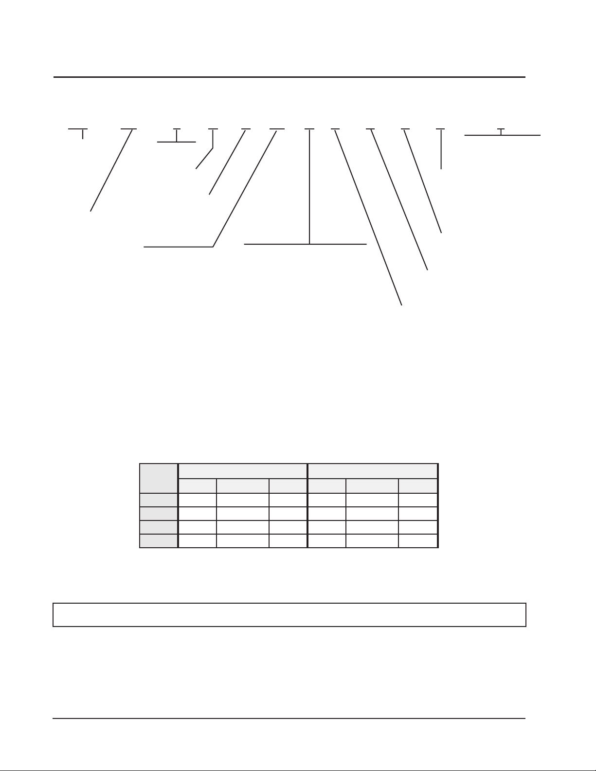
AIR CONDITIONER WALL MOUNT MODEL NOMENCLATURE
HA 4S 3 K A 05 B P X X X J
MODEL
NUMBER
HA – Right Hand
HL – Left Hand
CAPACITY
4S – 4 Ton
5S – 5 Ton
REVISION
K – Accumulator
VOLTS & PHASE
A – 230/208-1
KW
0Z –
No KW
w/Circuit Breaker
or Pull Disconnect
05 – 5 KW
08 – 8 KW
10 – 10 KW
15 – 15 KW
VENTILATION OPTIONS
B – Blank-off Plate (Standard)
FILTER OPTIONS
P – Two Inch Pleated
MERV 8
CONTROL MODULES
J – Only
COIL OPTIONS
X – Standard
1 - Phenolic Coated Evaporator
2 - Phenolic Coated Condenser
3 - Phenolic Coated Evaporator
and Condenser
OUTLET OPTIONS
X – Front (Standard)
COLOR OPTIONS
X – Beige (Standard)
4 – Buckeye Gray
5 – Desert Brown
8 – Dark Bronze
A – Aluminum
S – Stainless Steel
TABLE 1
ELECTRIC HEAT TABLE
lanimoN
WK
wK spmAhP-1 hutB wK spmAhP-1 hutB
0.50.58.02560,7157.30.81997,21
0.80.83.33403,7200.68.82874,02
0.010.017.14031,4305.71.63895,52
0.510.515.26591,1552.111.45693,83
)1(V042tA )1(V802tA
.ylnostinuV802/032nielbaliavaerasretaehcirtceleesehT)1(
See Table 3 for Heater Availability by Model
Manual 2100-573A
Page 4 of 21
Page 5
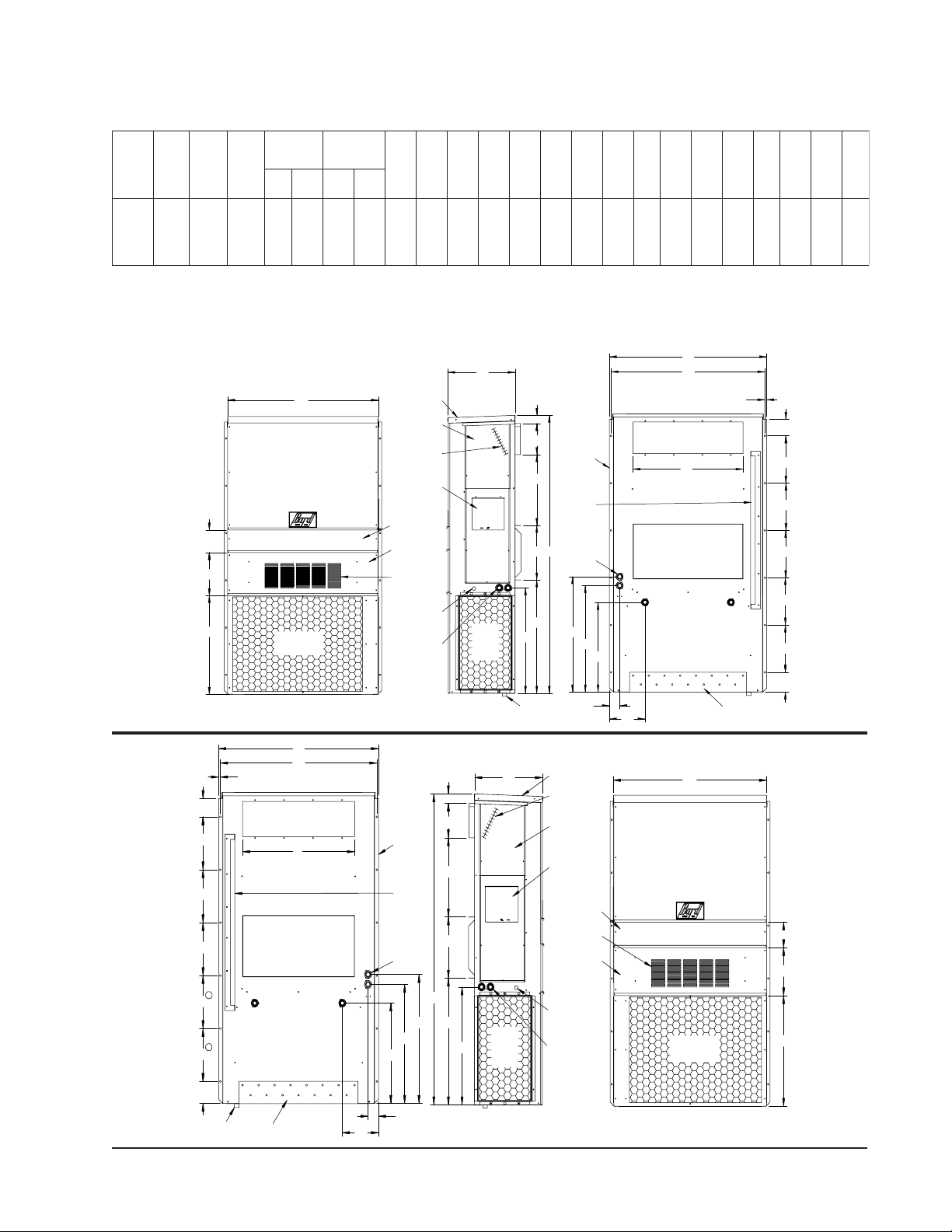
TABLE 2
DIMENSIONS OF BASIC UNIT FOR ARCHITECTURAL & INSTALLATION REQUIREMENTS (NOMINAL)
ylppuSnruteR
htdiW
htpeD
tinU
W
D
3S4AH
2S4LH
570.24234.22578.4988.988.9288.5188.9288.3401.9166.1400.0386.2449.6396.4434.2473.300.3488.3300.0144.100.6100.1288.1
3S5AH
2S5LH
All dimensions in inches. Dimensional Drawings are not to scale.
thgieH
H
EFGI JKLMNOPQRS12STAB C B
FIGURE 1 — UNIT DIMENSIONS
HA*S*
RIGHT
UNIT
5.75
Built In
W
F
G
Condenser
Air Outlet
Rain Hood
4° Pitch
Heater
Access
Panel
Electric
C. Breaker/
Disconnect
Access Panel
(Lockable)
Filter Access
Panel
Vent Option
Door
Ventilation
Air
Low Voltage
Electrical
Entrance
High Voltage
Electrical
Entrance
Heat
Front View
D
Cond.
Air
Inlet
Side View
J
Drain
2.13
Side Wall
A
Mounting
Brackets
(Built In)
I
Top Rain
Flashing
Shipping
Location
Optional
C
H
Electrical
Entrances
K
L
M
P
N
Q
E
O
Supply Air Opening
B
Return Air Opening
Back View
.44
Bottom Installation
Bracket
MIS-2762
R
S1
S1
S1
S2
S2
T
HL*S*
LEFT
UNIT
R
S
S
S
S
S
T
1
1
Drain
E
O
.44
Supply Air Opening
B
Return Air Opening
Back View
Bottom
Installation
Bracket
Built In
Rain Hood
4° Pitch
D
Electric
Heat
Heater
Access
Panel
C. Breaker/
Disconnect
Access Panel
(Lockable)
Filter Access
Panel
Ventilation
Vent Option
Door
Low Voltage
Electrical
Entrance
High Voltage
Electrical
Entrance
Air
Side Wall
Mounting
Brackets
(Built In)
Top Rain
Flashing
Shipping
Location
Optional
Electrical
Entrances
M
P
N
2.13
A
I
C
H
K
L
Cond.
J
Air
Inlet
Side View
Q
W
Condenser
Air Outlet
Front View
5.88
F
G
MIS-2488 C
Manual 2100-573A
Page 5 of 21
Page 6
eriW
2 dnuorG
eziSeriW
rewoP
2 dleiF
esuFlanretxE
.rkrB.tkCro
01
01
01
01
01
6
8
8
03
06
01
01
01
01
01
6
8
8
03
06
1 mumixaM
yticapmA
tiucriC
3 muminiM
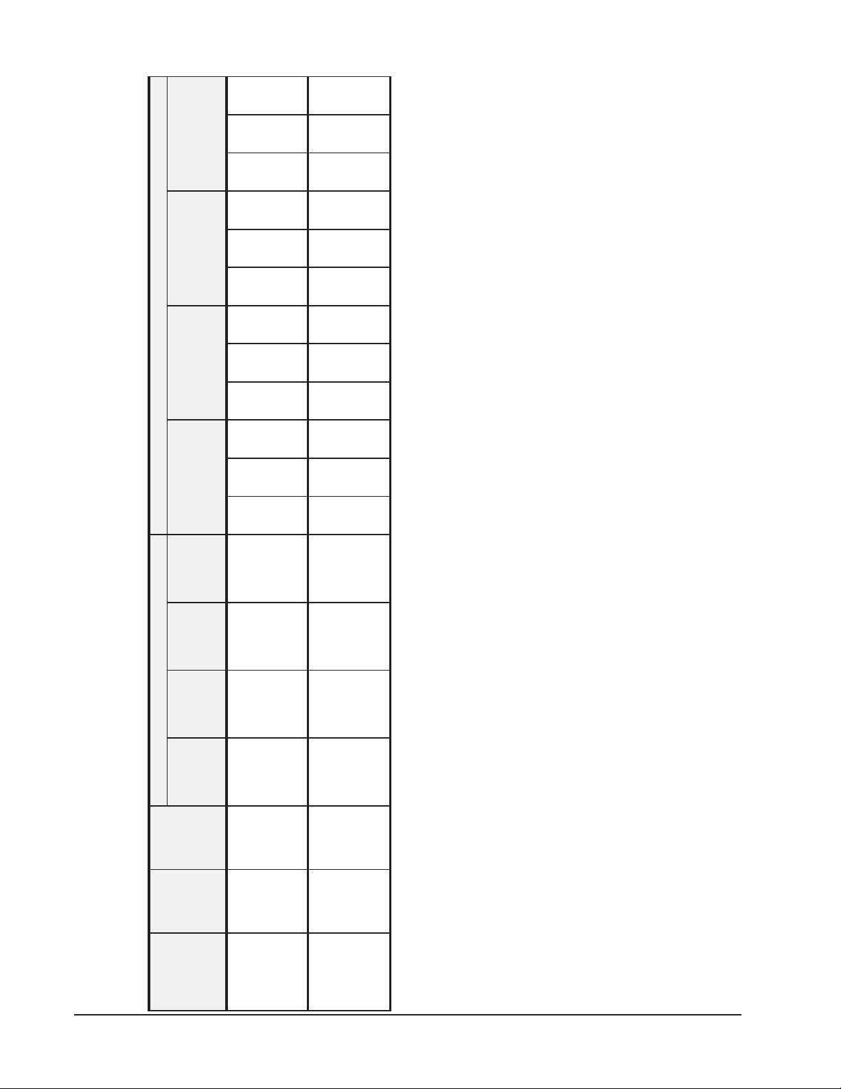
TABLE 3
ELECTRICAL SPECIFICATIONS
tiucriCelgniS tiucriCelpitluM
A.tkC B.tkC C.tkC A.tkC B.tkC C.tkC A.tkC B.tkC C.tkC A.tkC B.tkC C.tkC
eriW
010101
2 dnuorG
eziSeriW
rewoP
2 dleiF
esuFlanretxE
1 mumixaM
tiucriC
88643
.rkrB.tkCro
5454060709
yticapmA
8383353698
54
54
62
25
73
73
8
8
05
62
44
010101
8
88663
0505060709
4444353698
05
25
44
8
Manual 2100-573A
Page 6 of 21
3 muminiM
dleiF.oN
stiucriC
rewoP
esahPdna
detaR
stloV
ledoM
S4L/AH -
111
Z0A
50A-
2ro1
2ro1
1-802/032
111
2ro1
2ro1
1-802/032
CAUTION: When more than one filed power conductor circuit is run through one conduit, the conductors must be derated.
80A-
01A-
51A-
Z0A
50A-
80A-
01A-
51A-
S5L/AH -
conductor sizing.
Pay special attention to Note * of Table 310 regarding Ampacity Adjustment Factors when more than 3 conductors are in a raceway.
1 Maximum size of the time delay fuse or HACR type circuit breaker for protection of field wiring conductors.
2 Based on 75°C copper wire. All wiring must conform to the National Electric Code (NEC) and all local codes.
3 These “Minimum Circuit Ampacity” values are to be used for sizing the field power conductors. Refer to the National Electric Code (latest version), Article 310 for power
Page 7
SHIPPING DAMAGE
Upon receipt of equipment, the carton should be checked
for external signs of shipping damage. If damage is
found, the receiving party must contact the last carrier
immediately, preferably in writing, requesting inspection
by the carrier’s agent.
GENERAL
The equipment covered in this manual is to be installed
by trained, experienced service and installation
technicians.
The refrigerant system is completely assembled and
charged. All internal wiring is complete.
The unit is designed for use with or without duct work.
Flanges are provided for attaching the supply and return
ducts.
These instructions explain the recommended method to
install the air cooled self-contained unit and the
electrical wiring connections to the unit.
These instructions and any instructions packaged with
any separate equipment required to make up the entire
air conditioning system should be carefully read before
beginning the installation. Note particularly “Starting
Procedure” and any tags and/or labels attached to the
equipment.
Refer to Table 6 for maximum static pressure available
for duct design.
Design the duct work according to methods given by the
Air Conditioning Contractors of America (ACCA).
When duct runs through unheated spaces, it should be
insulated with a minimum of 1-inch of insulation. Use
insulation with a vapor barrier on the outside of the
insulation. Flexible joints should be used to connect the
duct work to the equipment in order to keep the noise
transmission to a minimum.
A 1/4 inch clearance to combustible material for the first
three feet of duct attached to the outlet air frame is
required. See Wall Mounting Instructions and Figures 3
and 4 for further details.
Ducts through the walls must be insulated and all joints
taped or sealed to prevent air or moisture entering the
wall cavity.
CAUTION
Some installations may not require any return
air duct. A return air grille is required with
installations not requiring a return air duct.
The spacing between louvers on the grille
shall not be larger than 5/8 inches.
While these instructions are intended as a general
recommended guide, they do not supersede any national
and/or local codes in any way. Authorities having
jurisdiction should be consulted before the installation is
made. See Page 3 for information on codes and
standards.
Size of unit for a proposed installation should be based
on heat loss calculation made according to methods of
Air Conditioning Contractors of America (ACCA). The
air duct should be installed in accordance with the
Standards of the National Fire Protection Association for
the Installation of Air Conditioning and Ventilating
Systems of Other Than Residence Type, NFPA No.
90A, and Residence Type Warm Air Heating and Air
Conditioning Systems, NFPA No. 90B. Where local
regulations are at a variance with instructions, installer
should adhere to local codes.
DUCT WORK
All duct work, supply and return, must be properly sized
for the design airflow requirement of the equipment. Air
Conditioning Contractors of America (ACCA) is an
excellent guide to proper sizing. All duct work or
portions thereof not in the conditioned space should be
properly insulated in order to both conserve energy and
prevent condensation or moisture damage.
Any grille that meets the 5/8 inch louver criteria, may be
used. It is recommended that Bard Return Air Grille Kit
RG-5 or RFG-5 be installed when no return duct is used.
Contact distributor or factory for ordering information.
If using a return air filter grille, filters must be of
sufficient size to allow a maximum velocity of 400 fpm.
NOTE: If no return air duct is used, applicable
installation codes may limit this cabinet to
installation only in a single story structure.
FILTERS
A 2-inch pleated MERV 8 filter is supplied with each
unit. The filter slides into position making it easy to
service. This filter can be serviced from the outside by
removing the filter access panel.
CONDENSATE DRAIN
A plastic drain hose extends from the drain pan at the top
of the unit down to the unit base. There are openings in
the unit base for the drain hose to pass through. In the
event the drain hose is connected to a drain system of
some type, it must be an open or vented type system to
assure proper drainage.
Manual 2100-573A
Page 7 of 21
Page 8

INSTALLATION INSTRUCTIONS
WALL MOUNTING INFORMATION
1. Two holes, for the supply and return air openings,
must be cut through the wall as shown in Figure 3.
2. On wood-frame walls, the wall construction must
be strong and rigid enough to carry the weight of the
unit without transmitting any unit vibration. See
Figures 4 and 5.
WARNING
Fire hazard can result if 1/4 inch clearance to
combustible materials for supply air duct is
not maintained. See Figure 3.
3. Concrete block walls must be thoroughly inspected
to insure that they are capable of carrying the weight
of the installing unit.
MOUNTING THE UNIT
1. These units are secured by wall mounting brackets
which secure the unit to the outside wall surface at
both sides. A bottom mounting bracket is provided
for ease of installation.
2. The unit itself is suitable for “0” inch clearance, but
the supply air duct flange and the first 3 feet of
supply air duct require a minimum of 1/4 inch
clearance to combustible material. If a combustible
wall, use a minimum of 30-1/2" x 10-1/2"
dimensions for sizing. However, it is generally
recommended that a 1-inch clearance is used for ease
of installation and maintaining the required
clearance to combustible material. The supply air
opening would then be 32" x 12". See Figures 2, 3
and 6 for details.
WARNING
Failure to provide the 1/4 inch clearance
between the supply duct and a combustible
surface for the first 3 feet of duct can result in
fire.
3. Locate and mark lag bolt locations and bottom
mounting bracket location. See Figure 4.
4. Mount bottom mounting bracket.
5. Hook top rain flashing under back bend of top. Top
rain flashing is shipped secured to the right side of
the back.
6. Position unit in opening and secure with 5/16" lag
bolts; use 7/8 inch diameter flat washers on the lag
bolts.
7. Secure rain flashing to wall and caulk across entire
length of top. See Figure 2.
8. For additional mounting rigidity, the return air and
supply air frames or collars can be drilled and
screwed or welded to the structural wall itself
(depending upon wall construction). Be sure to
observe required clearance if combustible wall.
9. On side-by-side installations, maintain a minimum
of 20 inches clearance on right side to allow access
to heat strips and control panel and to allow proper
airflow to the outdoor coil. Additional clearance
may be required to meet local or national codes.
TYPICAL INSTALLATIONS
See Figure 5 for common ways to install the wall mount
unit.
WIRING — MAIN POWER
Refer to the unit rating plate for wire sizing information
and maximum fuse or “HACR” type circuit breaker size.
Each outdoor unit is marked with a “Minimum Circuit
Ampacity”. This means that the field wiring used must
be sized to carry that amount of current. Depending on
the installed KW of electric heat, there may be two field
power circuits required. If this is the case, the unit serial
plate will so indicate. All models are suitable only for
connection with copper wire. Each unit and/or wiring
diagram will be marked “Use Copper Conductors Only”.
These instructions must be adhered to. Refer to the
National Electrical Code (NEC) for complete current
carrying capacity data on the various insulation grades
of wiring material. All wiring must conform to NEC
and all local codes.
The electrical data lists fuse and wire sizes (75ºC
copper) for all models, including the most commonly
used heater sizes. Also shown are the number of field
power circuits required for the various models with
heaters.
Manual 2100-573A
Page 8 of 21
Page 9

The unit rating plate lists a “Maximum Time Delay
Relay Fuse” or “HACR” type circuit breaker that is to
be used with the equipment. The correct size must be
used for proper circuit protection and also to assure that
there will be no nuisance tripping due to the momentary
high starting c urrent o f th e compressor motor.
To convert for the locking capability, bend the tab
located in the bottom left hand corner of the disconnect
opening under the disconnect access panel straight out.
This tab will now line up with the slot in the door.
When shut, a padlock may be placed through the hole in
the tab preventing entry.
The disconnect access door on this unit may be locked to
prevent unauthorized access to the disconnect.
MOUNTING INSTRUCTIONS
SEAL WITH BEAD
OF CAULKING ALONG
ENTIRE LENGTH OF
29
REQUIRED DIMENSIONS TO MAINTAIN
1/4" MIN. CLEARANCE FROM
COMBUSTIBLE MATERIALS
REQUIRED DIMENSIONS TO MAINTAIN
RECOMMENDED 1" CLEARANCE FROM
COMBUSTIBLE MATERIALS
D
16"
ABCDE
10 1/2
30 1/2
32 12 5 1/2
A CC
Supply Opening
6 1/4 1 1/4 29 3/4
2
B
See Start-up section for information on three phase
scroll compressor start-ups.
FIGURE 2
TOP.
TOP
WALL
HEATER ACCESS
PANEL
NOTE: It is recommended that a bead of silicone
caulking be placed behind the side mounting
flanges and under the top flashing at the
time of installation.
RAIN FLASHING
SUPPLIED
FOAM AIR SEAL
WALL STRUCTURE
1/4" CLEARANCE ON ALL
FOUR SIDES OF SUPPLY
AIR DUCT IS REQUIRED
FROM COMBUSTABLE
MATERIALS
SUPPLY AIR
DUCT
16"
16"
Return Opening
1
16"
1
6
"
2
1
16"
2
7
1
"
8
1
6
" 6
2
1
Dimension is 21" on 95" tall units.
2
Dimension is 10" on T48H1 & T60H1.
3
Dimension is 6" on T48H1 & T60H1.
Typ.
30"
1
Typ.
3
8
4"
3"
1"
4"
Wall Opening and Hole Location View
E
16"
"
7
"
8
1
3
2
"
8
1
"
2
Right Side View
RETURN AIR
OPENING
NOTES:
IT IS RECOMMENDED THAT A BEAD OF
SILICONE CAULKING BE PLACED BEHIND
THE SIDE MOUNTING FLANGES AND UNDER
TOP FLASHING AT TIME OF INSTALLATION.
MIS-416 E
Manual 2100-573A
Page 9 of 21
Page 10

FIGURE 3
WALL-MOUNTING INSTRUCTIONS
SEE FIGURE 3 — MOUNTING INSTRUCTIONS
SUPPLY AIR
OPENING
RETURN AIR
OPENING
CONCRETE BLOCK WAL L I NS T A LL ATION
SUPPLY AIR
OPENING
RETURN AIR
OPENING
WOOD OR STEEL SIDING
WOOD FRAME WALL INSTALLATION
FACTORY SUPPLIED
RAIN FLASHING.
MOUNT ON UNIT
BEFORE INSTALLATION
BOTTOM MOUNTING
BRACKET. MOUNT ON
WALL BEFORE
INSTALLING UNIT.
SIDE VIEW
WALL STRUCTURE
SUPPLY AIR
DUCT
RETURN AIR
OPENING
MIS-548 A
FIGURE 4
WALL-MOUNTING INSTRUCTIONS
SEE UNIT DIMENSIONS, FIGURE 1,
ATTACH TO TOP
PLATE OF WALL
1.000" CLEARANCE
ALL AROUND DUCT
INTERIOR FINISHED WALL
OVER FRAME
1.000" CLEARANCE
ALL AROUND DUCT
EXTERIOR FINISH WALL
OVER FRAME
FOR ACTUAL DIMENSIONS
SEE UNIT DIMENSIONS, FIGURE 2,
FOR ACTUAL DIMENSIONS.
E + 1.000
B
SUPPLY DUCT
OPENING
RETURN DUCT
OPENING
C
L
2 x 6
SEE FIGURE 1 FOR
DUCT DIMENSIONS
1.000
A
I
C
K
MIS-549 B
Manual 2100-573A
Page 10 of 21
FRAMING MATERIAL
2 x 4'S, 2 x 6'S &/OR
STRUCTURAL STEEL
ATTACH TO BOTTOM
PLATE OF WALL
THIS STRUCTURAL MEMBER
LOCATED TO MATCH STUD
SPACING FOR REST OF WALL.
A SECOND MEMBER MAY BE
REQUIRED FOR SOME WALLS.
Page 11

FIGURE 5
COMMON WALL-MOUNTING INSTALLATIONS
SUPPLY DUCT MAY BE LOCATED IN AN ATTIC
OR BELOW CEILING RAFTERS AS SHOWN
RAIN
FLASHING
OUTSIDE
WALL
RAIN
FLASHING
RAFTERS
FINISHED CEILING SURFACE
SUPPLY AIR DUCT
W/ GRILLE
RETURN AIR
OPENING W/ GRILLE
FREE AIR FLOW
SUPPLY DUCT MAYBE LOCATED IN AN ATTIC
OR BELOW CEILING RAFTERS AS SHOWN
RAFTERS
RAIN
FLASHING
OUTSIDE
WALL
RAIN
FLASHING
RAFTERS
SUPPLY AIR DUCT
FINISHED CEILING SURFACE
RETURN AIR
OPENING W/ GRILLE
DUCTED SUPPLY
RETURN AT UNIT NO DUCT
SUPPLY DUCT MAYBE LOCATED IN AN ATTIC
OR BELOW CEILING RAFTERS AS SHOWN
RAFTERS
SUPPLY AIR DUCT
OUTSIDE
WALL
FALSE WALL INSTALLATION
FINISHED
CEILING SURFACE
RETURN AIR
SPACE
WALL SLEEVE
FALSE WALL
RETURN AIR GRILLE
OUTSIDE
WALL
SUPPLY AIR DUCT
LOWERED
CEILING
CLOSET WALL
WALL
SLEEVE
RAISED FLOOR
RETURN AIR
SUPPLY AIR
GRILLE
FINISHED CEILING
CLOSET INSTALLATION
Manual 2100-573A
Page 11 of 21
SURFACE
RETURN AIR
GRILLE
MIS-550 B
Page 12

FIGURE 6
ELECTRIC HEAT CLEARANCE
NOTE 1: Side section view of supply air
duct for wall mounted unit showing 1/4
inch clearance to combustible surfaces.
W ARNING
• A minimum of 1/4 inch clearance must be maintained
between the supply air duct and combustible materials.
This is required for the first 3 feet of ducting.
• It is important to insure that the 1/4 inch minimum
spacing is maintained at all points.
• Failure to do this could result in overheating the
combustible material and may result in fire.
WIRING – MAIN POWER
Low Voltage Connection
These units use a 24-volt AC low voltage circuit.
The “R” terminal is the hot terminal and the “C”
terminal is grounded.
“G” terminal is the fan input.
“Y1” terminal is the compressor input for cooling
1-Stage units only
“W1” terminal is the 1st stage electric heat.
“W2” terminal is the 2nd stage heat (if equipped).
“1” NC (normally closed) lockout alarm.
“2” NO (normally open) lockout alarm.
“3” COM lockout alarm.
“4” & “5” dirty filter alarm NC (normally closed).
WIRING – LOW VOLTAGE WIRING
230/208V, 1 phase and 3 phase equipment dual
primary voltage transformers. All equipment leaves
the factory wired on 240V tap. For 208V operation,
reconnect from 240V to 208V tap. The acceptable
operating voltage range for the 240 and 208V taps are:
TAP RANGE
240 253 – 216
208 220 – 187
NOTE: The voltage should be measured at the field
power connection point in the unit and while the
unit is operating at full load (maximum
amperage operating condition).
For wiring size and connections, refer to MV4000
Controller Manual 2100-571.
DIRTY FILTER SWITCH & RELAY
These units include a dirty filter switch and relay. The
alarm output of relay is normally closed, open on
alarm and is connected to terminals 4 and 5 of the unit
low voltage terminal block.
Manual 2100-573A
Page 12 of 21
Page 13

START UP
These units require R-410A refrigerant and Polyol Ester
oil.
GENERAL:
1. Use separate service equipment to avoid cross
contamination of oil and refrigerants.
2. Use recovery equipment rated for R-410A
refrigerant.
3. Use manifold gauges rated for R-410A (800 psi/250
psi low).
4. R-410A is a binary blend of HFC-32 and HFC-125.
5. R-410A is nearly azeotropic - similar to R-22 and
R-12. Although nearly azeotropic, charge with
liquid refrigerant.
6. R-410A operates at 40-70% higher pressure than
R-22, and systems designed for R-22 cannot
withstand this higher pressure.
7. R-410A has an ozone depletion potential of zero,
but must be reclaimed due to its global warming
potential.
8. R-410A compressors use Polyol Ester oil.
9. Polyolester oil is hygroscopic; it will rapidly absorb
moisture and strongly hold this moisture in the oil.
10. A liquid line dryer must be used - even a deep
vacuum will not separate moisture from the oil.
11. Limit atmospheric exposure to 15 minutes.
12. If compressor removal is necessary, always plug
compressor immediately after removal. Purge with
small amount of nitrogen when inserting plugs.
SAFETY PRACTICES:
1. Never mix R-410A with other refrigerants.
2. Use gloves and safety glasses, Polyol Ester oils can
be irritating to the skin, and liquid refrigerant will
freeze the skin.
3. Never use air and R-410A to leak check; the
mixture may become flammable.
4. Do not inhale R-410A – the vapor attacks the
nervous system, creating dizziness, loss of
coordination and slurred speech. Cardiac
irregularities, unconsciousness and ultimate death
can result from breathing this concentration.
5. Do not burn R-410A. This decomposition
produces hazardous vapors. Evacuate the area if
exposed.
6. Use only cylinders rated DOT4BA/4BW 400.
7. Never fill cylinders over 80% of total capacity.
8. Store cylinders in a cool area, out of direct
sunlight.
9. Never heat cylinders above 125°F.
10. Never trap liquid R-410A in manifold sets, gauge
lines or cylinders. R-410A expands significantly
at warmer temperatures. Once a cylinder or line is
full of liquid, any further rise in temperature will
cause it to burst.
TOPPING OFF SYSTEM CHARGE
If a leak has occurred in the system, Bard Manufacturing
recommends reclaiming, evacuating (see criteria above),
and charging to the nameplate charge. Topping off the
system charge can be done without problems.
With R-410A, there are no significant changes in the
refrigerant composition during multiple leaks and
recharges. R-410A refrigerant is close to being an
azeotropic blend (it behaves like a pure compound or
single component refrigerant). The remaining refrigerant
charge, in the system, may be used after leaks have
occurred and then “top-off” the charge by utilizing the
pressure charts on the inner control panel cover as a
guideline.
REMEMBER: When adding R-410A refrigerant, it must
come out of the charging cylinder/tank as a liquid to
avoid any fractionation, and to insure optimal system
performance. Refer to instructions for the cylinder that
is being utilized for proper method of liquid extraction.
Manual 2100-573A
Page 13 of 21
Page 14

START UP CONTINUED
IMPORTANT INSTALLER NOTE
For improved start-up performance, wash the indoor coil
with a dishwasher detergent.
CRANKCASE HEATERS
All units covered in this manual are provided with
compressor crankcase heat.
This crankcase heater is a band type heater located
around the bottom of the compressor. This heater is
controlled by the crankcase heater relay. The heater is
only energized when the compressor is not running.
Crankcase heat is essential to prevent liquid refrigerant
from migrating to the compressor, preventing oil pump
out on compressor start-up and possible bearing or scroll
vane failure due to compressing a liquid.
The decal in Figure 7 is affixed to all model units
detailing start-up procedure. This is very important.
Please read carefully.
START-UP LABEL
HIGH & LOW PRESSURE SWITCH
All models covered by this Manual are supplied with a
remote reset high pressure switch and low pressure
switch. If tripped, this pressure switch may be reset by
turning the thermostat off then back on again.
FIGURE 7
IMPORTANT
These procedures must be followed at
initial start-up and at any time power
has been removed for 12 hours or
longer.
To prevent compressor damage which may
result from the presence of liquid
refrigerant in the compressor crankcase.
1. Make certain the room thermostat is in
the "off" position (the compressor is
not to operate).
2. Apply power by closing the system
disconnect switch. This energizes the
compressor heater which evaporates
the liquid refrigerant in the crankcase.
3. Allow 4 hours or 60 minutes per pound
of refrigerant in the system as noted
on the unit rating plate, whichever is
greater.
4. After properly elapsed time, the
thermostat may be set to operate the
compressor.
5. Except as required for safety while
servicing – Do not open system
disconnect switch.
7961-061
Manual 2100-573A
Page 14 of 21
Page 15

SERVICE HINTS
1. Maintain clean air filters at all times. Also, do not close
off or block supply and return air registers. This reduces
air flow through the system, which shortens equipment
service life as well as increasing operating costs.
2. Check all power fuses or circuit breakers to be sure they
are the correct rating.
3. Periodic cleaning of the outdoor coil to permit full and
unrestricted airflow circulation is essential.
Frequency of coil cleaning will depend on duty cycle of
equipment, type of use and installation site variables.
Telecommunication type installations in high traffic
areas or in areas none too frequent to airborne debris,
will require more frequent coil maintenance than those
in areas not subject to those conditions.
SEQUENCE OF OPERATION
NON-ECONOMIZER
Stage 1 (Y1) cooling call activates Step 1 (partial
capacity, 66%) of compressor capacity.
Stage 2 (Y2) cooling call activates Step 2 (full capacity,
100%) of compressor capacity.
COMPRESSOR CONTROL MODULE
The compressor control module is standard on the models
covered by this manual. The compressor control is an
anti-short cycle/lockout timer with high and low pressure
switch monitoring and alarm relay output.
Adjustable Delay On Make And Break Timer
On initial power up or anytime power is interrupted to the
unit, the delay on make period begins, which will be 2
minutes plus 10% of the delay on break setting. When
the delay on make is complete and the high pressure and
low pressure switches are closed, the compressor
contactor is energized. Upon shutdown the delay or
break timer starts and prevents restart until the delay on
break and delay on make periods have expired.
During routine operation of the unit with no power
interruptions, the compressor will operate on demand
with no delay.
High Pressure Switch and Lockout Sequence
If the high pressure switch opens, the compressor
contactor will de-energize immediately. The lockout
timer will go into a soft lockout and stay in soft lockout
until the high pressure switch closes and the delay on
break time has expired. If the high pressure switch
opens again in this same operating cycle, the unit will go
into manual lockout condition and the alarm relay circuit
will energize. Recycling the wall thermostat resets the
manual lockout.
Low Pressure Switch, Bypass and Lockout Sequence
If the low pressure switch opens for more than 120
seconds, the compressor contactor will de-energize and
go into a soft lockout. Regardless the state of the low
pressure switch, the contactor will reenergize after the
delay on make time delay has expired. If the low
pressure switch remains open, or opens again for longer
than 120 seconds the unit will go into manual lockout
condition and the alarm relay circuit will energize.
Recycling the wall thermostat resets the manual lockout.
Low Ambient Control
The fan cycling control cycles the fan motor on, once the
liquid refrigerant pressure reaches 350 psig, and off, once
it has dropped to 225 psig. It will continue to cycle
between these parameters depending on outdoor
temperatures and the load/stage of the system.
This cycling maintains a minimum liquid pressure
affecting the minimum suction pressure. This effect
insures an evaporating temperature that is slightly above
the point of ice formation on the evaporator.
Manual 2100-573A
Page 15 of 21
Page 16

Alarm Relay Output
Alarm terminal is output connection for applications
where alarm relay is employed. This terminal is
powered whenever compressor is locked out due to HPC
or LPC sequences as described.
NOTE: Both high and low pressure switch controls
are inherently automatic reset devices. The
high pressure switch and low pressure
switch cut out and cut in settings are fixed by
specific air conditioner or heat pump unit
model. The lockout features, both soft and
manual, are a function of the Compressor
Control Module.
ADJUSTMENTS
Adjustable Delay on Make and Delay on Break
Timer
The potentiometer is used to select Delay on Break time
from 30 seconds to 5 minutes. Delay on Make (DOM)
timing on power-up and after power interruptions is
equal to 2 minutes plus 10% of Delay on Break (DOB)
setting:
0.5 minute (30 seconds) DOB =123 second DOM
1.0 minute (60 seconds) DOB =126 second DOM
2.0 minute (120 seconds) DOB =132 second DOM
3.0 minute (180 seconds) DOB =138 second DOM
4.0 minute (240 seconds) DOB =144 second DOM
5.0 minute (300 seconds) DOB =150 second DOM
MOTOR START DEVICE
Single Phase (-A) model compressor circuits are
equipped with a 25 ohm PTCR (Positive Temperature
Coefficient Resistor) motor starting device as standard
equipment.
The PTCR is wired in parallel with the run capacitor.
When voltage is applied, and device is cool, its low
resistance permits a large current to flow in the auxiliary
windings - increasing the motors available starting
torque. The device then rapidly heats up, and the current
levels drop to a few milliamperes. The PTCR then
becomes self-regulating, passing just enough current to
maintain its temperature to remain in the high resistance
state. Once the voltage source is removed, the device
then cools down and the resistance drops, and is then
ready for the next compressor start cycle.
PRESSURE SERVICE PORTS
High and low pressure service ports are installed on all
units so that the system operating pressures can be
observed. Pressure tables can be found later in the
manual covering all models. It is imperative to match
the correct pressure table to the unit by model number.
Be careful to observe whether unit is operating in high
cool or low cool when utilizing the charts.
During routine operation of the unit with no power
interruptions the compressor will operate on demand
with no delay.
Typical Settings for Dual Unit Installation:
Unit 1: DOB set at 2 minutes, and DOM is 132 seconds
Unit 2: DOB set at 4 minutes, and DOM is 144 seconds
Manual 2100-573A
Page 16 of 21
Page 17

TROUBLESHOOTING
COMPRESSOR SOLENOID
A nominal 24-volt direct current coil activates the
internal compressor solenoid. The input control circuit
voltage must be 18 to 28 volt ac. The coil power
requirement is 20 VA. The external electrical
connection is made with a molded plug assembly. This
plug contains a full wave rectifier to supply direct
current to the unloader coil.
Compressor Solenoid Test Procedure If it is
suspected that the unloader is not working, the following
methods may be used to verify operation.
1. Operate the system and measure compressor
amperage. Cycle the compressor solenoid on and off
at ten-second intervals. The compressor amperage
should go up or down at least 25 percent.
2. If step one does not give the expected results, shut
unit off. Apply 18 to 28 volt ac to the solenoid
molded plug leads and listen for a click as the
solenoid pulls in. Remove power and listen for
another click as the solenoid returns to its original
position.
3. If clicks can’t be heard, shut off power and remove
the control circuit molded plug from the compressor
and measure the solenoid coil resistance. The
resistance should be 32 to 60 ohms depending on
compressor temperature.
4. Next, check the molded plug.
Voltage check: Apply control voltage to the plug wires (18
to 28 volt ac). The measured
connectors in the plug should be around 15 to 27 vdc.
Resistance check: Measure the resistance from the end of
one molded plug lead to either of the two female connectors
in the plug. One of the connectors should read close to zero
ohms, while the other should read infinity. Repeat with
other wire. The same female connector as before should
read zero, while the other connector again reads infinity.
Reverse polarity on the ohmmeter leads and repeat. The
female connector that read infinity previously should now
read close to zero ohms.
Replace plug if either of these test methods does not
show the desired results.
dc voltage at the female
FAN BLADE SETTING DIMENSIONS
Shown in the drawing below are the correct fan blade
setting dimensions for proper air delivery across the
outdoor coil. See Figure 8.
Any service work requiring removal or adjustment in the
fan and/or motor area will require that the dimensions
below be checked and blade adjusted in or out on the
motor shaft accordingly. See Table 4.
FIGURE 8
FAN BLADE SETTING
AIRFLOW
"A"
MIS-1724
TABLE 4
FAN BLADE DIMENSIONS
ledoMAnoisnemiD
S4L/AH
S5L/AH
REMOVAL OF FAN SHROUD
1. Disconnect all power to unit.
2. Remove the screws holding both grills – one on
each side of unit – and remove grills.
3. Remove screws holding fan shroud to condenser and
bottom – (9) screws.
4. Unwire condenser fan motor.
5. Slide complete motor, fan blade, and shroud
assembly out the left side of the unit.
6. Service motor/fan as needed.
7. Reverse steps to reinstall.
"57.1
Manual 2100-573A
Page 17 of 21
Page 18

TROUBLESHOOTING CONT’D.
R-410A
REFRIGERANT CHARGE
This unit was charged at the factory with the quantity
of refrigerant listed on the serial plate. AHRI capacity
and efficiency ratings were determined by testing with
this refrigerant charge quantity.
COOLING PRESSURE – (ALL TEMPERATURES °F)
GNILOOCYTICAPACHGIH
LEDOM
S4AH
S4LH
S5AH
S5LH
RIANRUTER
ERUTAREPMET
BD°57
BW°26
BD°08
BW°76
BD°58
BW°27
BD°57
BW°26
BD°08
BW°76
BD°58
BW°27
ERUSSERP 05oF 55oF 06oF 56oF 07oF 57oF 08oF 58oF 09oF 59oF 001oF 501oF 011oF 511oF
EDISWOL
711
911
EDISHGIH
791
EDISWOL
721
EDISHGIH
102
EDISWOL
141
EDISHGIH
302
EDISWOL
811
EDISHGIH
991
EDISWOL
921
EDISHGIH
502
EDISWOL
731
EDISHGIH
612
121
612
532
921
131
022
932
341
541
322
342
911
021
712
632
031
131
422
742
931
041
732
852
TABLE 5
321
521
552
472
431
631
952
872
841
051
362
382
221
321
062
582
131
231
072
292
141
241
972
003
The following pressure tables show nominal pressures
for the units. Since many installation specific
situations can affect the pressure readings, this
information should only be used by certified
technicians as a guide for evaluating proper system
performance. They shall not be used to adjust charge.
If charge is in doubt, reclaim, evacuate and recharge
the unit to the serial plate charge.
FEERGEDLIOCROODTUOGNIRETNEERUTAREPMETRIA
721
821
031
131
231
331
531
392
613
933
163
383
014
831
831
931
931
341
892
813
143
463
251
251
351
303
623
521
621
903
333
231
431
513
933
341
641
123
643
351
943
273
821
921
753
183
731
931
363
783
841
151
073
593
341
004
514
451
651
693
224
031
231
504
234
141
341
524
834
351
551
914
744
631
834
664
441
641
344
174
851
061
944
874
331
531
064
784
541
641
564
294
751
851
474
205
731
494
941
005
261
805
631
415
841
915
061
925
LEDOM
S4AH
S4LH
S5AH
S5LH
Low side pressure ± 4 psig
High side pressure ± 10 psig
RIANRUTER
ERUTAREPMET
BD°57
BW°26
BD°08
BW°76
BD°58
BW°27
BD°57
BW°26
BD°08
BW°76
BD°58
BW°27
Manual 2100-573A
Page 18 of 21
GNILOOCYTICAPACWOL
ERUSSERP 05oF 55oF 06oF 56oF 07oF 57oF 08oF 58oF 09oF 59oF 001oF 501oF 011oF 511oF
EDISWOL
221
421
521
721
921
131
131
231
EDISHGIH
481
102
812
632
452
272
192
EDISWOL
231
431
631
831
041
241
EDISHGIH
581
302
122
932
752
EDISWOL
541
741
941
251
EDISHGIH
781
502
322
EDISWOL
321
521
EDISHGIH
781
EDISWOL
431
EDISHGIH
291
EDISWOL
641
EDISHGIH
002
721
702
622
631
831
112
032
841
941
712
532
451
142
952
921
131
542
362
931
141
842
762
151
251
252
072
541
572
892
651
651
872
793
331
431
282
503
341
541
682
803
451
651
782
113
331
213
533
641
741
713
933
751
851
913
343
531
631
823
053
741
941
133
353
951
161
533
853
FEERGEDLIOCROODTUOGNIRETNEERUTAREPMETRIA
431
531
731
931
953
183
704
841
941
263
951
963
731
373
151
573
361
283
051
483
014
161
361
093
514
931
141
993
524
351
551
204
924
561
661
804
434
141
534
364
151
251
834
764
461
561
344
274
341
541
154
774
651
851
654
384
861
961
064
684
Page 19

TROUBLESHOOTING GE ECM
™
MOTORS
CAUTION:
Disconnect power from unit before removing or replacing
connectors, or servicing motor. To avoid electric shock
from the motor’s capacitors, disconnect power and wait at
least 5 minutes before opening motor.
Symptom Cause/Procedure
Motor rocks slightly • This is normal start-up for ECM
when starting
Motor won’t start • Check blower turns by hand
• No movement
• Motor rocks, • Check for loose or compliant motor mount
but won’t start
Motor oscillates up • It is normal for motor to oscillate with no load
& down while being on shaft
tested off of blower
Motor starts, but
runs erratically
• Varies up and down • Check line voltage for variation or “sag”
or intermittent • Check low voltage connections
• “Hunts” or “puffs” at • Does removing panel or filter reduce
high CFM (speed) “puffing”?
• Stays at low CFM • Check low voltage (Thermostat) wires and
despite system call connections
for cool or heat CFM • Verify fan is not in delay mode; wait until
• Stays at high CFM • “R” missing/not connected at motor
• Blower won’t shut off •
Excessive noise • Determine if it’s air noise, cabinet, duct or
• Air noise • High static creating high blower speed?
• Check power at motor
• Check low voltage (24 Vac R to C) at motor
• Check low voltage connections
(G, Y, W, R, C) at motor
• Check for unseated pins in connectors on
motor harness
• Test with a temporary jumper between R - G
• Check motor for tight shaft
• Perform motor/control replacement check
• Perform Moisture Check
• Make sure blower wheel is tight on shaft
• Perform motor/control replacement check
(G, Y, W, R, C) at motor, unseated pins in
motor harness connectors
• Check “Bk” for erratic CFM command (in
variable-speed applications)
• Check out system controls, Thermostat
• Perform Moisture Check
- Reduce restriction
- Reduce max airflow
delay complete
• “R” missing/not connected at motor
• Perform motor/control replacement check
• Is fan in delay mode? - wait until delay time
complete
• Perform motor/control replacement check
Current leakage from controls into G, Y or W?
Check for Triac switched thermostat or solid state relay
motor noise; interview customer, if necessary
- Is airflow set properly?
- Does removing filter cause blower to slow
down? Check filter
- Use low-pressure drop filter
- Check/correct duct restrictions
Symptom Cause/Procedure
• Noisy blower or cabinet • Check for loose blower housing, panels, etc.
• “Hunts” or “puffs” at • Does removing panel or filter reduce
high CFM (speed)
Evidence of Moisture
• Motor failure or • Replace motor and
malfunction has occurred
and moisture is present
• Evidence of moisture • Perform Moisture Check
present inside air mover
• High static creating high blower speed?
- Check for air whistling through seams in
ducts, cabinets or panels
- Check for cabinet/duct deformation
“puffing”?
- Reduce restriction
- Reduce max. airflow
Perform Moisture Check
Do Don’t
• Check out motor, controls, • Automatically assume the motor is bad.
wiring and connections
thoroughly before replacing
motor
• Orient connectors down so • Locate connectors above 7 and 4 o’clock
water can’t get in positions
- Install “drip loops”
• Use authorized motor and • Replace one motor or control model # with
model #’s for replacement another (unless an authorized replacement)
• Keep static pressure to a • Use high pressure drop filters some have
minimum: H20 drop!
- Recommend high • Use restricted returns
efficiency, low static filters
- Recommend keeping filters
clean.
- Design ductwork for min.
static, max. comfort
- Look for and recommend
ductwork improvement,
where necessary
• Size the equipment wisely • Oversize system, then compensate with low
airflow
• Check orientation before • Plug in power connector backwards
inserting motor connectors • Force plugs
½"
Moisture Check
• Connectors are oriented “down” (or as recommended by equipment
manufacturer)
• Arrange harness with “drip loop” under motor
• Is condensate drain plugged?
• Check for low airflow (too much latent capacity)
• Check for undercharged condition
• Check and plug leaks in return ducts, cabinet
Comfort Check
• Check proper airflow settings
• Low static pressure for lowest noise
• Set low continuous-fan CFM
• Use humidistat and 2-speed cooling units
• Use zoning controls designed for ECM that regulate CFM
• Thermostat in bad location?
Manual 2100-573A
Page 19 of 21
Page 20

TROUBLESHOOTING GE ECM
™
MOTORS CONT’D.
Replacing ECM Control Module
To replace the control module for the GE variable-speed indoor blower
motor you need to take the following steps:
1. You MUST have the correct replacement module. The controls are
factory programmed for specific operating modes. Even though they look
alike, different modules may have completely different functionality.
USING THE WRONG CONTROL MODULE VOIDS ALL PRODUCT
WARRANTIES AND MAY PRODUCE UNEXPECTED RESULTS.
2. Begin by removing AC power from the furnace or air handler being
serviced. DO NOT WORK ON THE MOTOR WITH AC POWER
APPLIED. To avoid electric shock from the motor’s capacitors, disconnect
power and wait at least 5 minutes before opening motor.
3. It is usually not necessary to remove the motor from the blower
assembly. However, it is recommended that the whole blower assembly, with
the motor, be removed from the furnace/air handler. (Follow the
manufacturer’s procedures). Unplug the two cable connectors to the motor.
There are latches on each connector. DO NOT PULL ON THE WIRES.
The plugs remove easily when properly released.
4. Locate the two standard
housing (at the back end of the control opposite the shaft end). Refer to
Figure 9. Remove these two bolts from the motor and control
assembly while holding the motor in a way that will prevent the motor
or control from falling when the bolts are removed. If an ECM2.0
control is being replaced (recognized by an aluminum casting rather
that a deep-drawn black steel can housing the electronics), remove
only the hex-head bolts. DO NOT REMOVE THE TORX-HEAD
SCREWS.
5. The control module is now free of mechanical attachment to the
motor endshield but is still connected by a plug and three wires inside the
control. Carefully rotate the control to gain access to the plug at the
control end of the wires. With thumb and forefinger, reach the latch
holding the plug to the control and release it by squeezing the latch tab
and the opposite side of the connector plug and gently pulling the plug out
of the connector socket in the control. DO NOT PULL ON THE
WIRES. GRIP THE PLUG ONLY.
6. The control module is now completely detached from the motor.
Verify with a standard ohmmeter that the resistance from each motor lead
(in the motor plug just removed) to the motor shell is >100K ohms. Refer
to Figure 10. (Measure to unpainted motor end plate.) If any motor
lead fails this test, do not proceed to install the control module. THE
MOTOR IS DEFECTIVE AND MUST BE REPLACED. Installing
the new control module will cause it to fail also.
7. Verify that the replacement control is correct for your
application. Refer to the manufacturer's authorized replacement list.
USING THE WRONG CONTROL WILL RESULT IN
IMPROPER OR NO BLOWER OPERATION. Orient the control
module so that the 3-wire motor plug can be inserted into the socket in
the control. Carefully insert the plug and press it into the socket until
it latches. A SLIGHT CLICK WILL BE HEARD WHEN
PROPERLY INSERTED.
one of the three following paragraphs, 8a, 8b or 8c.
8a. IF REPLACING AN ECM 2.0 CONTROL (control in cast
aluminum can with air vents on the back of the can) WITH AN ECM 2.3
CONTROL (control containing black potting for water protection in
black deep-drawn steel case with no vents in the bottom of the can), locate
the two through-bolts and plastic tab that are packed with the replacement
control. Insert the plastic tab into the slot at the perimeter of the open end
of the can so that the pin is located on the inside of the perimeter of the
can. Rotate the can so that the tab inserts into the tab locater hole in the
endshield of the motor. Using the two through-bolts provided with the
replacement control, reattach the can to the motor.
THE TWO THROUGH-BOLTS PROVIDED WITH THE
REPLACEMENT ECM 2.3 CONTROL ARE SHORTER THAN THE
BOLTS ORIGINALLY REMOVED FROM THE ECM 2.0
CONTROL AND MUST BE USED IF SECURE ATTACHMENT OF
THE CONTROL TO THE MOTOR IS TO BE ACHIEVED.
DO NOT OVERTIGHTEN THE BOLTS.
¼" hex head bolts at the rear of the control
Finish installing the replacement control per
8b. IF REPLACING AN ECM 2.3 CONTROL WITH AN ECM 2.3
CONTROL, the plastic tab and shorter through-bolts are not needed. The
control can be oriented in two positions 180° apart. MAKE SURE THE
ORIENTATION YOU SELECT FOR REPLACING THE CONTROL
ASSURES THE CONTROL'S CABLE CONNECTORS WILL BE
LOCATED DOWNWARD IN THE APPLICATION SO THAT
WATER CANNOT RUN DOWN THE CABLES AND INTO THE
CONTROL. Simply orient the new control to the motor's endshield,
insert bolts, and tighten. DO NOT OVERTIGHTEN THE BOLTS.
8c. IF REPLACING AN ECM 2.0 CONTROL WITH AN ECM
2.0 CONTROL (It is recommended that ECM 2.3 controls be used for
all replacements), the new control must be attached to the motor using
through bolts identical to those removed with the original control. DO
NOT OVERTIGHTEN THE BOLTS.
9. Reinstall the blower/motor assembly into the HVAC equipment.
Follow the manufacturer's suggested procedures.
10. Plug the 16-pin control plug into the motor. The plug is keyed.
Make sure the connector is properly seated and latched.
11. Plug the 5-pin power connector into the motor. Even though the
plug is keyed, OBSERVE THE PROPER ORIENTATION. DO NOT
FORCE THE CONNECTOR. It plugs in very easily when properly
oriented. REVERSING THIS PLUG WILL CAUSE IMMEDIATE
FAILURE OF THE CONTROL MODULE.
12.
Final installation check. Make sure the motor is installed as follows:
a.Unit is as far INTO the blower housing as possible.
b.Belly bands are not on the control module or covering vent holes.
c.Motor connectors should be oriented between the 4 o’clock and 8
o’clock positions when the blower is positioned in its final
location and orientation.
d.Add a drip loop to the cables so that water cannot enter the motor
by draining down the cables. Refer to Figure 11.
The installation is now complete. Reapply the AC power to the
HVAC equipment and verify that the new motor control module is
working properly. Follow the manufacturer's procedures for
disposition of the old control module.
Back of
Control
Figure 10
Figure 4
Winding Test
Motor OK when
R > 100k ohm
Figure 11
Figure 5
Drip Loop
Connector Orientation
Between 4 and 8 o'clock
Drip Loop
Only remove
Hex Head Bolts
ECM 2.0
Note:
Use the shorter
bolts and
alignment pin
supplied when
replacing an
ECM 2.0
control.
Figure 9
Figure 3
Control Disassembly
Push until
Latch Seats
Over Ramp
ECM
2.3/2.5
Hex-head Screws
From Motor
Circuit
Board
Motor
Motor Connector
(3-pin)
Control Connector
(16-pin)
Power Connector
(5-pin)
Motor Connector
(3-pin)
Manual 2100-573A
Page 20 of 21
Page 21

TABLE 6
INDOOR BLOWER PERFORMANCE
11
1
11
ledoMPSEdetaRPSEXAM
22222
suounitnoC
MFC
33333
44444
ts1detaR
MFCegatS
dn2detaR
MFCegatS
S4L/AH 02.008.05280011005100110051
S5L/AH 02.008.00580031007100110051
1 Motor will deliver consistent CFM through voltage supply range with no deterioration.
(197-253V for 230/208V models, 414-506V for 460V models)
2 Continuous CFM is the total air being circulated during continuous (manual) fan mode.
3 Will occur automatically with a call for "Y1" signal from thermostat.
4 Will occur automatically with a call for "Y2" signal from thermostat.
5 Will occur automatically with a call for "W1" signal from thermostat.
6 Will occur automatically with a call for "W2" or "Emergency Heat" signal from thermostat.
TABLE 7 — OPTIONAL ACCESSORIES
LEDOMNOITPIRCSED
50A-S4AWHEegakcaPretaeH
01A-S4AWHEegakcaPretaeH
51A-S4AWHEegakcaPretaeH
50A-S5AWHEegakcaPretaeH
80A-S5AWHEegakcaPretaeH
01A-S5AWHEegakcaPretaeH
51A-S5AWHEegakcaPretaeH
5-POB)dradnatS(etalPffOknalB
HA4S3KA
X
X
X
XX
XX
55555
WK01-5
MFC
66666
WK02-51
MFC
HA5S3KA
X
X
X
TABLE 8 — OPTIONAL ACCESSORIES
LEDOMNOITPIRCSED
L50A-S4AWHEegakcaPretaeH
L01A-S4AWHEegakcaPretaeH
L51A-S4AWHEegakcaPretaeH
L50A-S5AWHEegakcaPretaeH
L01A-S5AWHEegakcaPretaeH
L51A-S5AWHEegakcaPretaeH
5-POB)dradnatS(etalPffOknalB
HL4S2KA
X
X
X
XX
HL5S2KA
X
X
X
Manual 2100-573A
Page 21 of 21
 Loading...