

INSTALLATION INSTRUCTIONS
SPLIT AIR CONDITIONER
OUTDOOR SECTION
Models:
HAC181-AD040
HAC241-AD040
HAC301-AD040
HAC361-AD040
HAC421-AD040
HAC481-AD040
HAC481-BD040
HAC601-AD040
HAC601-BD040
FOR USE WITH:
MA TCHING INDOOR
BLOWER COIL UNITS
AND MA TCHING ADD
ON COIL UNITS ONLY
Bard Manufacturing Company
Bryan, Ohio 43506
Since 1914 . . . Moving ahead just as planned.
Manual No.: 2100-346C
Supersedes: 2100-346B
File: Volume 1, Tab 4
Date: 09-04-02
© Copyright 2002

CONTENTS
Split Air Conditioner General Information......... 1
Split Air Conditioner Model Nomenclature ............... 1
Application and Location ....................................4
General .................................................................... 4
Shipping Damage .................................................... 4
Application ............................................................... 4
Location ................................................................... 4
Mounting Unit Outside on Slab................................. 4
Important Installer Note............................................ 4
Installing Refrigerant Tubing..................................... 4
Sweat Style Tubin Connections: Sweat
Indoor Unit and Sweat Outdoor Unit ........................ 5
Field Fabricated Tubing Connections:
Quick Connect Indoor Unit and Sweat
Outdoor Unit Using CTO Kit..................................... 6
Wiring Instructions ..............................................9
General .................................................................... 9
Control Circuit Wiring ............................................... 9
Wall Thermostats..................................................... 9
Optional Controls ................................................... 12
Installation Instructions – CMA-5 ............................ 12
Installation Instructions – CMA-6 ............................ 12
Installation Instructions – CMA-10A........................ 13
Installation Instructions – CMA-13A........................ 14
Charging Instructions ........................................ 15
Pressure Service Ports .......................................... 15
System Start-Up (Indoor Units
without Expansion V alves....................................... 15
Service ................................................................17
Service Hints.......................................................... 17
Fan Blade Setting Dimensions ............................... 17
Pressure T ables ................................................ 20-23
FIGURES
Figure 1.................................................................... 1
Figure 2.................................................................... 4
Figure 3.................................................................... 5
Figure 4.................................................................... 5
Figure 5.................................................................. 12
Figure 6.................................................................. 12
Figure 7.................................................................. 12
Figure 8.................................................................. 13
Figure 9.................................................................. 14
TABLES
Table 1 ..................................................................... 1
Table 2 ..................................................................... 2
Table 3 ..................................................................... 3
Table 4 ..................................................................... 6
Table 6 ..................................................................... 9
Table 7 ..................................................................... 9
Table 8 ..................................................................... 9
Table 9 ................................................................... 15
Table 10 ................................................................. 15
Table 11 ................................................................. 16
Table 12 ................................................................. 17
Table 13 ................................................................. 20
Table 14 ................................................................. 20
Table 15 ................................................................. 21
Table 16 ................................................................. 21
Table 17 ................................................................. 22
Table 18 ................................................................. 22
Table 19 ................................................................. 23
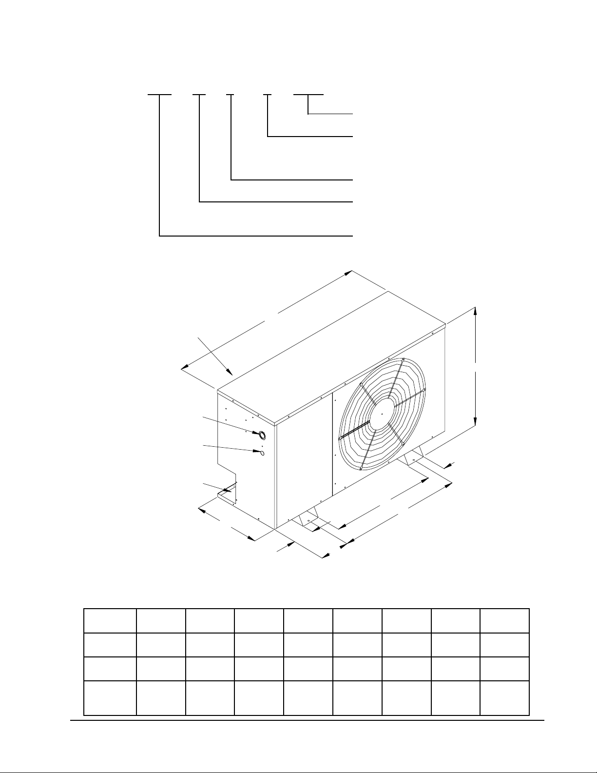
SPLIT AIR CONDITIONER MODEL NOMENCLATURE
HAC 36 1 – A DXXX
FIGURE 1
UNIT DIMENSIONAL DRAWING
Customized Unit Code
Electrical Characteristics
A – 230/208-60-1
B – 230/208-60-3
Modification Code
Capacity – 3 Ton or
approx. 36,000 BTU
Basic Model Number
ALTERNATE
ELECTRICAL
ENTRANCES
ON BACK
HIGH VOLTAGE
ENTRANCE
LOW VOLTAGE
ENTRANCE
REFRIGERANT
SHUTOFF
VALVES
D
W
H
C
B
F
A
E
MIS-1789
TABLE 1
UNIT DIMENSIONS
"W"
.oNledoM
181CAH
142CAH
103CAH
163CAH
htdiW
00.0400.5100.62521.5881.0200.4521.7881.42
00.5400.5100.62521.5881.5200.4521.7881.92
"D"
htpeD
"H"
thgieHABCEF
124CAH
184CAH
00.0500.5100.23526.6886.8200.4526.8886.23
106CAH
Manual 2100-346
Page 1
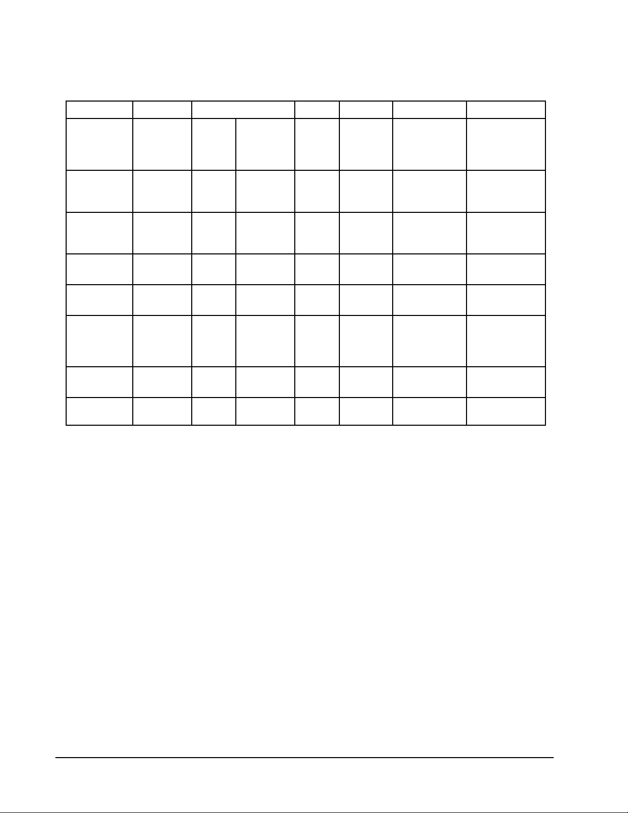
TABLE 2
RATED CFM AND AIR FLOW DATA
(WET COIL – COOLING)
wolfriAdetaR
gnisnednoC
tinU
.oNledoM
A-181CAH
A142CAH
A-103CAH
A-163CAH
A-124CAH
B-,A-184CAH
B-,A-106CAH
rotaropavE
lioC
.oNledoM
A-SA03A
A-SA42S
B42CB
A-SA03A
A-SA42S
B42CB
A-SA63A
B63CB
A-SA73A
B63CB
A-SA24A
A-SA84A
B63CB
B06CB
B-SA16A
B06CB
B-SA16A
B06CB
MFC
056
056
056
008
087
057
000,1
000,1
001,1
001,1
004,1
005,1
002,1
005,1
007,1
007,1
067,1
008,1
erusserP
O
HporD
2
51.
42.
81.
03.
02.
81.
03.
62.
82.
03.
detaR
.P.S.E
53.deM
02.hgiH
03.woL
72.hgiH
51.
83.
52.woL
82.hgiH
rotoM
deepS
paT
hgiH
woL
dednemmoceR
egnaRwolFriA
517-055
517-055
517-055
019-007
098-086
019-007
571,1-058
571,1-058
022,1-029
022,1-029
055,1-072,1
526,1-052,1
023,1-020,1
526,1-052,1
578,1-054,1
578,1-054,1
059,1-005,1
579,1-525,1
metsyS
ecifirO
deriuqeR
250.
250.
250.
550.
550.
550.
360.
360.
960.
960.
870.
870.
870.
870.
180.
180.
290.
290.
*
*
*
*
*
*
*
*
*
*
*
*
*
*
Q Measured across the evaporator coil assembly, including drain pan.
R External static pressure available for the duct system -- supply and return. All blower coils have multispeed
motors, and value shown is at the recommended rated speed. Consult specification air flow charts with the
blower coil units for complete information at other speeds.
* IMPORT ANT INFORMA TION
Proper sized orifice is not factory installed in indoor section. Proper orifice size is shipped with outdoor unit
packaged with its installation instructions for indoor sections listed on this page. The orifice must be replaced
with the proper system orifice shown above in T able 2.
For other evaporator coil models not listed, see indoor coil installation instructions for proper orifice information.
Manual 2100-346
Page 2
!
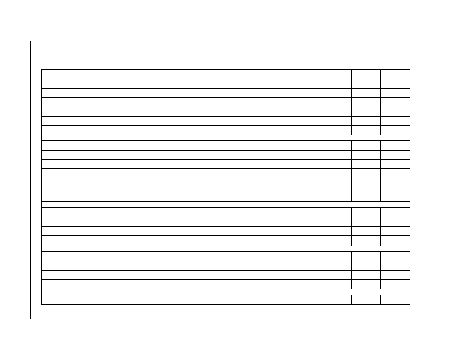
TABLE 3
SPECIFICATIONS
SLEDOMA-181CAHA-142CAHA-103CAHA-163CAHA-124CAHA-184CAHB-184CAHA-106CAHB-106CAH
)HP/V/ZH06(gnitaRlacirtcelE1-802/0321-802/0321-802/0321-802/0321-802/0321-802/0323-802/0321-802/0323-802/032
egnaRegatloVgnitarepO352-791352-791352-791352-791352-791352-791352-781352-791352-781
yticapmAtiucriCmuminiM515191025262715312
¬
eziSeriWdleiF41412121010121801
rekaerBtiucriCromumixaMesuFyaleD020203030454520653
802/032spmAtinUlatoT6.8/9.74.11/2.010.41/4.318.51/5.416.91/1.910.12/4.914.31/8.217.62/7.222.71/3.51
ROSSERPMOC
802/032stloV802/032802/032802/032802/032802/032802/032802/032802/032802/032
spmAdaoLdetaR5.7/8.63.01/1.99.21/3.217.41/4.311.81/6.715.91/9.719.11/3.112.52/2.127.51/8.31
tnerruCnoitceleStiucriChcnarB6.83.017.317.411.815.916.213.627.51
802/032spmArotoRkcoL94/9465/6557/5728/28501/501201/20119/19531/531051/051
taeHesacknarCenoNenoNenoNenoN
RESNEDNOCdnaROTOMNAF
MPR/PH–rotoMnaF528–6/1528–6/1528–6/1528–6/1528–4/1528–4/1528–4/1528–4/1528–4/1
spmA–rotoMnaF1.11.11.11.15.15.15.15.15.1
noisremmI
epyT
noisremmI
epyT
noisremmI
epyT
enoNenoN
Manual 2100-346
Page 3
retemaiD–naF000,2–"02000,2–"02000,2–"02000,2–"02006,2–"42006,2–"42006,2–"42006,2–"42006,2–"42
METSYSTCENNOCTAEWS
DIeziSeniLnoitcuS"8/5"4/3"4/3"4/3"8/7"8/7"8/7"8/7"8/7
DIeziSeniLdiuqiL"4/1"8/3"8/3"8/3"8/3"8/3"8/3"8/3"8/3
.zO22-RegnahCyrotcaF.zo37.zo97.zo48.zo69.zo201.zo551.zo551.zo351.zo351
.SBL–THGIEWGNIPPIHS
551551081081052052052552552
APPLICATION and LOCATION
GENERAL
These instructions explain the recommended method to
install the air cooled remote type condensing unit, the
interconnecting refrigerant tubing and the electrical wiring
connections to the unit.
The condensing units are to be used in conjunction with the
matching evaporator coils or evaporator blower units for
comfort cooling applications as shown in the specification
sheet.
These instructions and any instructions packaged with any
separate equipment required to make up the entire air
conditioning system should be carefully read before
beginning the installation. Note particularly “Starting
Procedure” and any tags and/or labels attached to the
equipment.
SHIPPING DAMAGE
Upon receipt of equipment, the carton should be checked for
external signs of shipping damage. If damage is found, the
receiving part must contact the last carrier immediately,
preferably in writing, requesting inspection by the carrier’s
agent.
APPLICATION
LOCATION
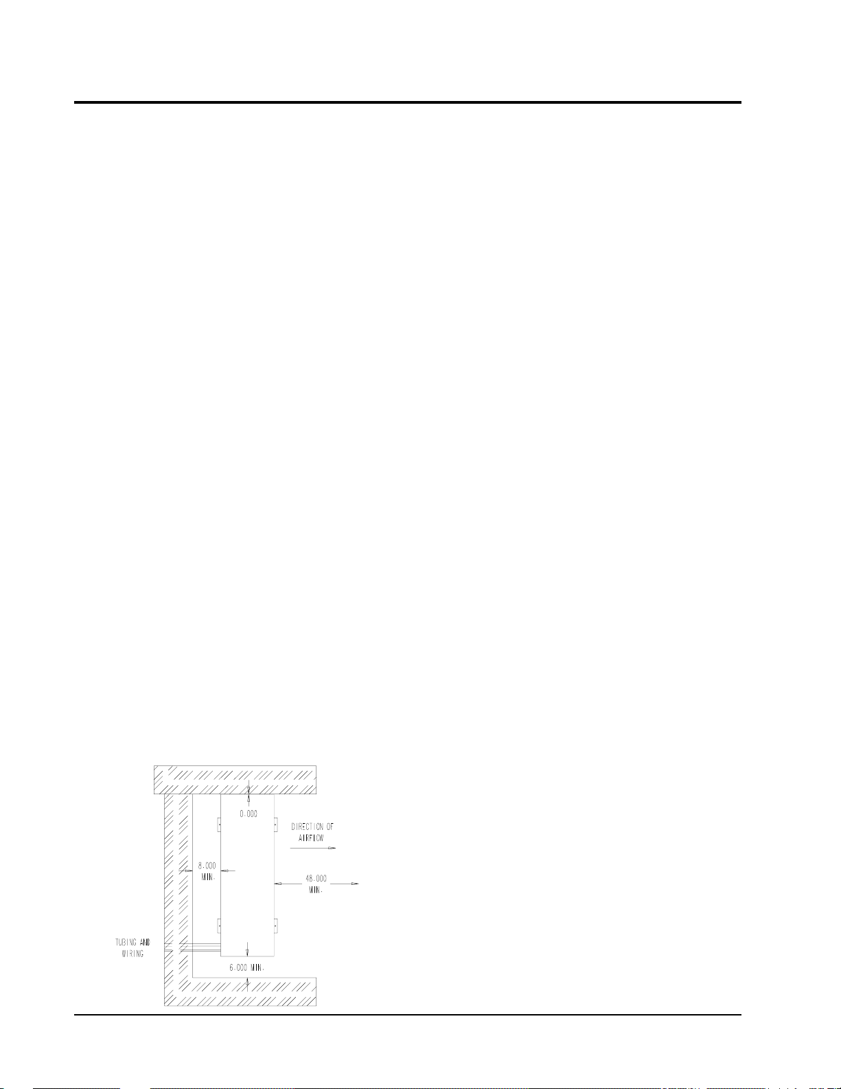
The condensing unit is designed to be located outside with
free and unobstructed condenser air inlet and discharge. It
must also permit access for service and installation.
Condenser air enters the coil from the rear of the unit as
shown in Figure 2 with electrical service access.
MOUNTING UNIT OUTSIDE ON SLAB
A solid level base or platform, capable to support the unit’s
weight, must be set at the outdoor unit predetermined
location. The base should be at least two inches larger than
the base dimensions of the unit and at least two inches
higher than surrounding grade level. The required unit
minimum installed clearances must be maintained as called
out in Figure 2 when locating and setting the base.
Remove the unit from its shipping carton and position the
unit on the prepared base or platform.
NOTE: These units employ internally sprung
compressors; therefore, it is not necessary to
remove or loosen the base mounting bolts on the
compressor prior to operation.
Consideration should be given to the electrical and tubing
connections when placing the unit to avoid unnecessary
bends or length of material.
Size of unit for a proposed installation should be based on
heat loss calculation and air duct sizing made according to
methods of Air Conditioning Contractors of America. The
air duct should be installed in accordance with the Standards
of the National Fire Protection Association for the
Installation of Air Conditioning and Ventilating Systems of
Other Than Residence Type, NFPA 90A, and Residence
Type Warm Air Heating and Air Conditioning Systems,
NFPA 90B. Where local regulations are at a variance with
instructions, installer should adhere to local codes.
FIGURE 2
INSTALLATION CLEARANCE
IMPORTANT INSTALLER NOTE
For improved start up performance, wash the indoor coil
with a dishwashing detergent.
INSTALLATION REFRIGERANT TUBING
The information that follows on installing refrigerant tubing
and for changing the system orifice (if required) covers
applications listed in the front of this installation instruction
only. Although other indoor units may be of similar
construction, the installation instructions for these units
should be consulted for proper installation of those units
prior to installation.
This information is provided for the field service personnel
to install refrigerant tubing in compliance with Section 608
of Title VI National Recycling and Emission Reduction
Program for the U.S. Clean Air Act effective July 1, 1992.
Consult manual 2100-002 on procedure for leak test –
evacuation – charging before installation refrigerant tubing
that requires any refrigerant recovery or system evacuation.
Manual 2100-002 is included with the unit installation
instruction package when shipped from the factory.
Manual 2100-346
Page 4
MIS-589
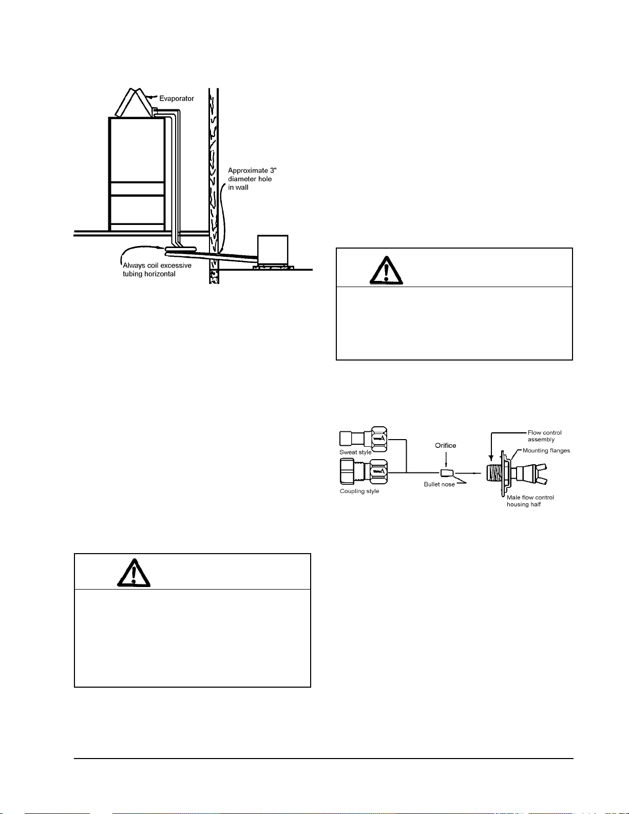
FIGURE 3
INSTALLING REFRIGERANT TUBING
NOTE:
If the orifice does not have to be changed, skip the
instructions outlined further in Step 3 and proceed to Step 8.
3. Disassemble Flow Control Assembly by turning body
4. If existing orifice has not dropped out of the body when
5. Insert proper sized orifice fully into the flow control
Do not braze line to units! If orifice needs to be
changed, change out orifice first.
hex.
disassembled, remove by using a pin or paper clip.
Discard this original orifice.
body with rounded “bullet” nose towards the unit as
shown in Figure 4. Insure the orifice stays inserted in
body before connecting mating half. See chart in the
outdoor unit installation instructions for proper size.
pp5
SWEAT STYLE TUBING CONNECTIONS: SWEAT
INDOOR UNIT and SWEAT OUTDOOR UNIT
Use only refrigeration grade (dehydrated and sealed) copper
tubing. Care must be taken to insure that the tubing is kept
clean and dry before and during installation. Do not remove
the plugs from the tubing ends, coil connections or base
valves until the connection is ready to be brazed.
The suction line must be insulated with a minimum of 3/8”
Armaflex or equivalent before cutting and making
connections.
1. Being careful not to kink, route both the suction line
and liquid line between the indoor unit and outdoor
unit. Use a tubing bender to make any necessary bends
in tubing. When necessary to bend the insulated tube
suction line, cut the insulation around its circumference
at a distance far enough beyond the point of the bend so
as to clear the tubing bender. Slip the insulation back
together and vapor seal the joint with tape. Coil any
excess tubing in a horizontal place with the slope of the
tubing toward the condensing unit. See Figure 3.
CAUTION
1. Be careful not to tear the insulation when
pushing it through hole in masonry or frame
walls. 2. When sealing the tube opening in
house wall, use a soft material to prevent tube
damage and vibration transmission. 3. Avoid
excessive bending in any one place to avoid
kinking.
2. The tubing ends should be cut square. Make sure it is
round and free of burrs at the connecting ends. Clean
the tubing to prevent contaminants from entering the
system.
CAUTION
Be sure there is no dirt introduced into the flow
control - orifice assembly . Be sure to install the
orifice with the bullet nose pointing in the proper
direction as shown in Figure 4. Failure to do so
will result in improper operation.
FIGURE 4
FLOW CONTROL ASSEMBLY
FIELD ORIFICE REPLACEMENT INSTRUCTIONS
pp5
6. Thread assembly halves together by hand to insure
proper mating of threads and tighten until bodies
“bottom” or a definite resistance is felt.
7. Using a marker pen or ink pen, mark a line lengthwise
from the union nut to the bulkhead. Then tighten an
additional 1/6 turn (or 1 hex flat). The misalignment of
the line will show the amount the assembly has been
tightened. This final 1/6 turn is necessary to insure the
formation of the leakproof joint.
8. Wrap a wet rag around the copper stub before brazing.
9. Flux the copper tube and insert into the stub. Braze the
joint using an alloy of silver or copper and phosphorus
with a melting temperature above 1,100° F for copper
to copper joints. The phosphorus will act as a flux,
therefore, no flux will be required.
Manual 2100-346
Page 5
A copper-silver alloy with a high silver content should
be used when iron or steel material is involved in the
joint. These alloys require the use of silver solder flux.
Alloys containing phosphorus should not be used with
iron or steel. Phosphorus reacts with the iron forming
iron phosphate which is extremely brittle.
FIELD FABRICATED TUBING CONNECTIONS:
QUICK CONNECT INDOOR UNIT and SWEAT
OUTDOOR UNIT USING CTO KIT
Use only refrigeration grade (dehydrated and sealed) copper
tubing. Care must be taken to insure that the tubing is kept
clean and dry before and during installation. Do not remove
the plugs from the tubing ends, coil connections or base
valves until the connection is ready to be brazed.
CAUTION
1. Brazing alloys with a melting temperature
below 700° F should not be used. 2. Leadtin or tin-antimony solders should not be used
due to their low melting point and necessity for
corrosive fluxes.
To further prevent the formation of copper oxide inside
the tubing, dry nitrogen may be purged through the
refrigerant system during brazing.
WARNING
Never purge or pressurize a system with
oxygen. An explosion and fire will result.
10. After brazing, quench with wet rag to cool the joint and
remove any flux residue.
11. Leak test all connections using an electronic leak
detector or a halide torch.
The suction line must be insulated with a minimum of 3/8”
Armaflex or equivalent before cutting and making
connections.
1. Being careful not to kink, route both the suction line and
liquid line between the indoor unit and outdoor unit. Use
a tubing bender to make any necessary bends in tubing.
When necessary to bend the insulated tube suction line,
cut the insulation around its circumference at a distance
far enough beyond the point of the bend so as to clear the
tubing bender. Slip the insulation back together and
vapor seal the joint with tape. Coil any excess tubing in
a horizontal place with the slope of the tubing toward the
condensing unit. See Figure 3.
CAUTION
1. Be careful not to tear the insulation when
pushing it through hole in masonry or frame
walls. 2. When sealing the tube opening in
house wall, use a soft material to prevent tube
damage and vibration transmission. 3. Avoid
excessive bending in any one place to avoid
kinking.
12. Evacuate suction line, liquid line and indoor unit
through outdoor unit base valves.
13. Open both the suction and liquid base valves to the
fully open position. Refer to section later in installation
instructions for details on setting proper system charge.
cisaB
gnisnednoC
ledoMtinU
181CAH"4/1"8/5"4/1"8/5"8/3"4/3
142CAH"8/3"8/5"8/3"4/3"8/3"4/3
103CAH"8/3"8/5"8/3"4/3"8/3"4/3
163CAH"8/3"8/5"8/3"4/32/1"8/7
124CAH"8/3"4/3"8/3"8/72/1"8/7
184CAH"8/3"8/7"8/3"8/72/1"8/1-1
106CAH"8/3"8/7"8/3"8/72/1"8/1-1
Manual 2100-346
Page 6
diuqiLnoitcuSdiuqiLnoitcuSdiuqiLnoitcuS
TABLE 4
TUBING CHART
).tF(htgneLeniLtnaregirfeR
02-006-12001-16
2. The tubing ends should be cut square. Make sure it is
round and free of burrs at the connecting ends. Clean
the tubing to prevent contaminants from entering the
system.
NOTE: Do not make any tubing connection at indoor unit
at this time. Make all brazing of joints and
evacuate both suction and liquid line first.
3. Wrap a wet rag around the copper stub before brazing.
4. Flux the copper tube and insert into the stub. Braze the
joint using an alloy of silver or copper and phosphorus
with a melting temperature above 1,100° F for copper
to copper joints. The phosphorus will act as a flux,
therefore, no flux will be required.
A copper-silver alloy with a high silver content should
be used when iron or steel material is involved in the
joint. These alloys require the use of silver solder flux.
Alloys containing phosphorus should not be used with
iron or steel. Phosphorus reacts with the iron forming
iron phosphate which is extremely brittle.
8. Recover charge from the indoor unit.
A. Connect the suction line only to the indoor unit as
outlined in Steps 15, 16, and 17.
B. Recover indoor unit and suction line unit charge
through service port located on outdoor unit base
valve.
9. Disassemble Flow Control Assembly by turning body
hex.
10. If existing orifice has not dropped out of the body when
disassembled, remove by using a pin or paper clip.
Discard this original orifice.
11. Insert proper sized orifice fully into the flow control
body with rounded “bullet” nose towards the unit as
shown in Figure 4. Insure the orifice stays inserted in
body before connecting mating half. See chart in the
outdoor unit installation instructions for proper size.
To further prevent the formation of copper oxide inside
the tubing, dry nitrogen may be purged through the
refrigerant system during brazing.
CAUTION
1. Brazing alloys with a melting temperature
below 700° F should not be used. 2. Lead-tin
or tin-antimony solders should not be used due
to their low melting point and necessity for
corrosive fluxes.
WARNING
Never purge or pressurize a system with
oxygen. An explosion and fire will result.
5. After brazing, quench with wet rag to cool the joint and
remove any flux residue.
6. Leak test all connections using an electronic leak
detector or a halide torch.
7. Evacuate suction line and liquid line through outdoor
unit base valves.
CAUTION
Be sure there is no dirt introduced into the flow
control – orifice assembly. Be sure to install the
orifice with the bullet nose pointing in the proper
direction as shown in Figure 4. Failure to do so
will result in improper operation.
12. Thread assembly halves together by hand to insure
proper mating of threads and tighten until bodies
“bottom” or a definite resistance is felt.
13. Using a marker pen or ink pen, mark a line lengthwise
from the union nut to the bulkhead. Then tighten an
additional 1/6 turn (or 1 hex flat). The misalignment of
the line will show the amount the assembly has been
tightened. This final 1/6 turn is necessary to insure the
formation of the leakproof joint.
14. Evacuate the suction line and indoor unit through the
outdoor unit base valve before connecting all other
tubing. Refer to section later in installation instructions
for details on setting the proper refrigerant charge.
15. Remove (remaining) protector caps and plugs (if orifice
was changed). Inspect fittings and if necessary
carefully wipe coupling seats and threaded surfaces
with a clean cloth to prevent the inclusion of dirt or any
foreign material in the system.
If orifice does not have to be changed, skip the instructions
outlined further in Step 8 and proceed to Step 15.
Manual 2100-346
Page 7

16. Lubricate male half diaphragm and synthetic rubber
seal with refrigerant oil. Thread coupling halves
together by hand to insure proper mating of threads. Be
sure to hold the coupling firmly to prevent movement of
the coupling and tubing. Failure to do so could tear out
the diaphragm causing a blockage of the system. Use
proper size wrenches (on coupling body hex and on
union nut) and tighten until coupling bodies ”bottom”
or a definite resistance is felt.
TABLE 5
COUPLINGS
eziSgnilpuoCsdnuoPteeF
6-21-01
01-54-53
11-54-53
21-56-05
CAUTION
After starting to tighten up the fitting, never try to
back it off or take it apart.
17. Using a marker or ink pen, mark a line lengthwise from
the coupling union nut to the bulkhead. Then tighten
an additional 1/4 turn. The misalignment of the line
will show the amount the coupling has been tightened.
This final 1/4 turn is necessary to insure the formation
of leakproof joint. If a torque wrench is used, the
torque values shown in Table 5 are recommended.
18. Leak test all connections using an electronic leak
detector or a halide torch.
19. When tubing is installed in attics or drop ceilings,
insulate the couplings on the larger tube thoroughly
with 3/8” wall thickness, closed cell sponge tube
insulation or equivalent. Failure to insulate will result
in water damage to ceiling since the fitting will “sweat”
and drop water on the ceiling.
Manual 2100-346
Page 8

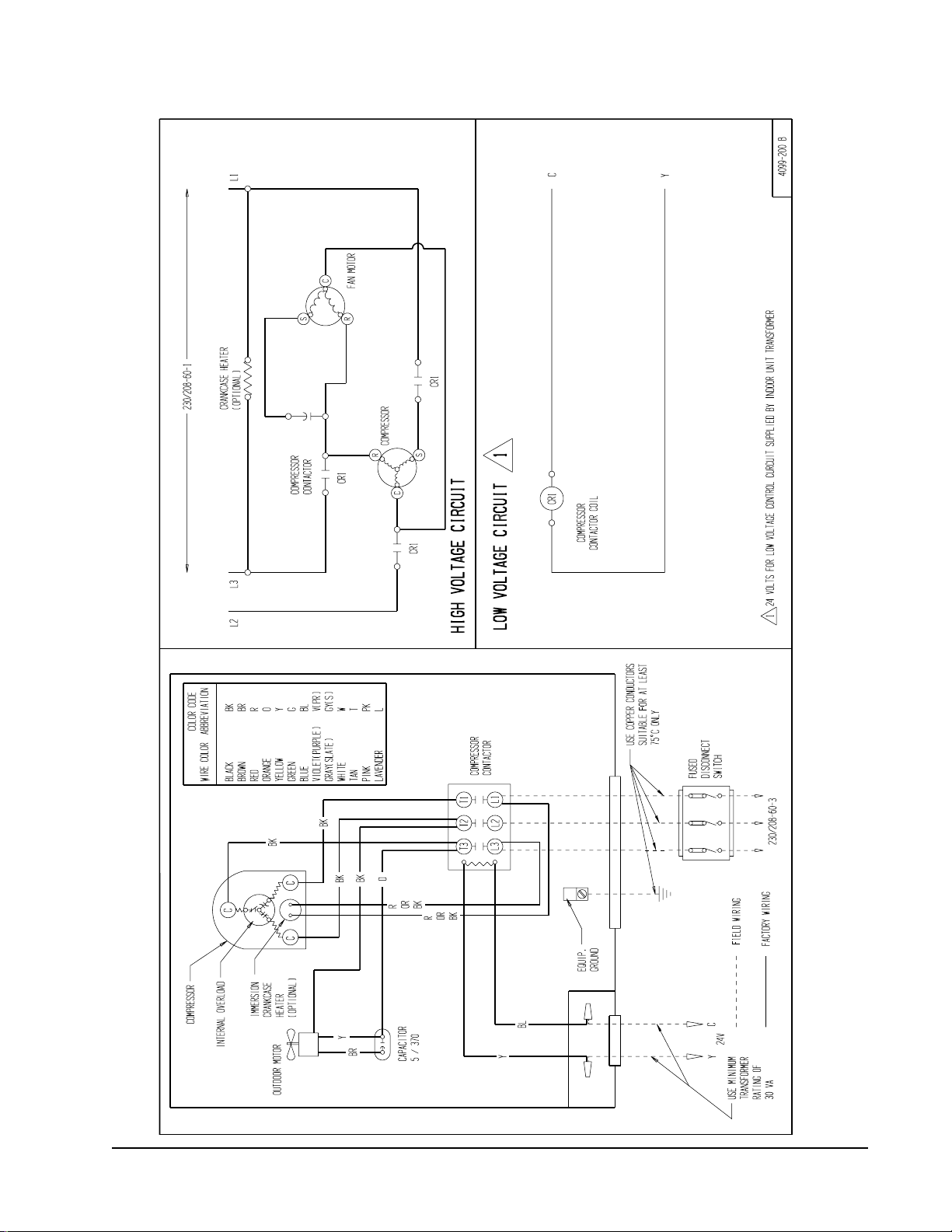
WIRING INSTRUCTIONS
GENERAL
All wiring must be installed in accordance with the National
Electrical Code and local codes. In Canada, all wiring must
be installed in accordance with the Canadian Electrical
Code and in accordance with the regulations of the
authorities having jurisdiction. Power supply voltage must
conform to the voltage shown on the unit serial plate. A
wiring diagram of the unit is attached to the inside of the
electrical cover. The power supply shall be sized and fused
according to the specification supplied. A ground lug is
supplied in the control compartment for equipment ground.
The unit rating plate lists a “Maximum Time Delay Fuse” or
HACR type” circuit breaker that is to be used with the
equipment. The correct size must be used for proper circuit
protection and also to assure that there will be no nuisance
tripping due to the momentary high starting current of the
compressor motor.
CONTROL CIRCUIT WIRING
For split systems, the minimum control circuit wiring gauge
needed to insure proper operation of all controls in both
indoor and outdoor units will depend on two factors:
1. The rated VA of the control circuit transformer.
Example: 1 . Control circuit transformer rated at 40 VA
2. Maximum total distance of control circuit
wiring 85 feet.
From Table 6, minimum of 18 gauge wire should be used in
the control circuit wiring.
For control circuit transformers rated other than those listed,
use the next lower rated transformer listed.
Example: 1 . Control circuit transformer rated at 55 VA
From table use 50VA transformer.
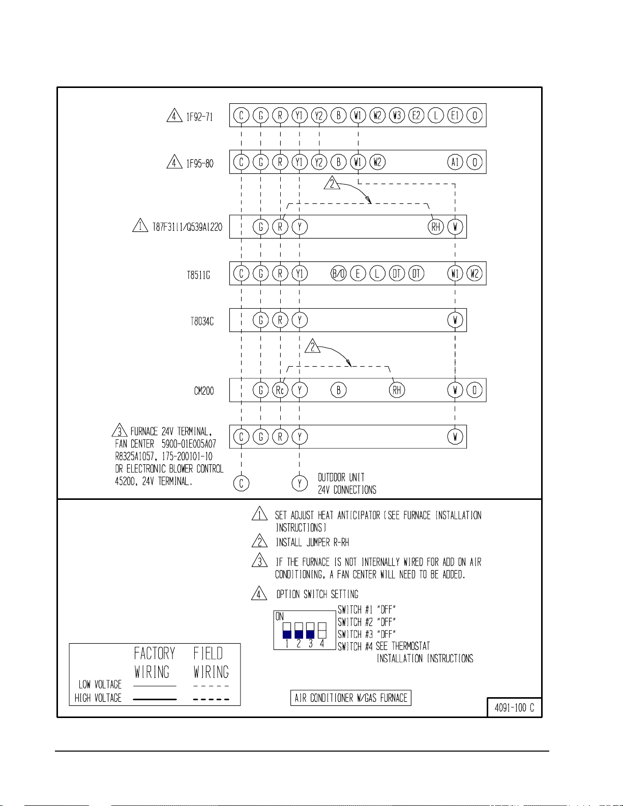
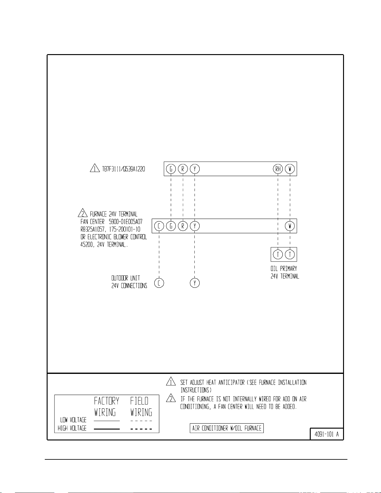
There are two (2) separate control diagrams for fossil fuel
furnaces with air conditioners.
Control diagrams for the various circuit which could be
encountered with blower coils can be found in the
installation instructions of the blower coil.
TABLE 7
CONTROL DIAGRAMS
metsyS
sledoMllA001-1904101-1904
ecanruFsaG
margaiDlortnoC
ecanruFliO
margaiDlortnoC
2. The maximum total distance of the control circuit
wiring. (This is the distance between the wall
thermostat to the indoor unit plus the distance
between the indoor unit to the outdoor unit.)
The following table should be used to determine proper
gauge of control circuit wiring required.
TABLE 6
CONTROL CIRCUIT WIRING
foAVdetaR
tiucriClortnoC
remrofsnarT
046.1
051.2
567.2
remrofsnarT
yradnoceS
V42@ALF
WALL THERMOSTATS
The following wall thermostats and subbases should be
used as indicated, depending on the application.
TABLE 8
WALL THERMOSTAT and SUBBASE
COMBINATIONS
latoTmumixM
foecnatsiD
tiucriClortnoC
teeFnigniriW
56eguag02
09eguag81
541eguag61
032eguag41
54eguag02
06eguag81
001eguag61
061eguag41
052eguag21
04eguag02
55eguag81
58eguag61
531eguag41
012eguag21
tatsomrehTesabbuSserutaeFetanimoderP
200-3048
113F78T
140-3048
C-4308T
530-3048
08-59F1
240-3048
G1158T
340-3048
002MC
720-3048
17-29F1
300-4048
0221A925Q
---
---
---
---
---
yrucreM;loocegats1,taehegats1
otua-no:naFlooc-ffo-taeh:metsyS
yrucreM;loocegats1,taehegats1
otua-no:naFlooc-ffo-taeh:metsyS
loocegats2,taehegats2
elbammargorP
cinortcelE
loocegats1,taehegats2
looc-otua-ffo-taeh:metsyS
cinortcelEotua-no:naF
loocegats1,taehegats1
otua-no:naFlooc-ffo-taeh:metsyS
noitcApanS
loocegats2,taehegats3
elbammargorP
cinortcelE
Manual 2100-346
Page 9
Manual 2100-346
Page 10
Manual 2100-346
Page 11

OPTIONAL CONTROLS
INSTALLATION INSTRUCTIONS — CMA-6
FIGURE 5
COMPONENT MOUNTING LOCATION
CMA-5 & CMA-13A LOW
CMA-5 COMPRESSOR
TIME DELA Y RELAY
SK109 LOW VOLTAGE
START KIT
MIS-1302
AMBIENT FAN CYCLING
CONTROL TERMINAL BLOCK
CMA-10A & CMA-13A
COMPRESSOR
CONTROL
INSTALLATION INSTRUCTIONS — CMA-5
Disconnect all power to the unit. Remove control panel
cover.
1. Mount compressor TDR in position shown in Figure 5
with screw provided.
2. Disconnect yellow low voltage (Y) wire at the
compressor contactor coil and reconnect to the Y1 or #3
terminal of the TDR.
3. Connect yellow wire from terminal (Y) of the TDR to
the (Y) terminal of the compressor contactor coil. This
is the terminal that the wire was removed from in
Step 2.
4. Recheck wiring. Refer to Figure 9. Energize unit.
Compressor should start. Remove power and reapply.
Compressor should not start until the 5 minute time
delay has expired.
Disconnect all power to unit. Remove control panel inner
and outer cover.
1. Mount terminal block in position shown in Figure 5.
2. Disconnect black high voltage outdoor motor lead from
compressor contactor and reconnect to terminal block.
3. Route low ambient control wires up through the
bushing in the bottom of the control panel. Connect the
low ambient control wires between the terminal block
and T2 of the compressor contactor.
4. Remove service port cap on discharge line. Install the
low ambient control on the discharge line with the flare
tee adapter that is brazed to the low ambient control.
Check for pressure at the flare tee dill valve after
installation to insure that the dill valve in the unit
service port was depressed by the flare tee connector.
Check for leaks at the flare tee connectors. Replace
service port cap on the flare tee service port and tighten.
5. Recheck wiring. See Figure 10. Check for proper
operation of the unit by energizing in cooling mode.
The condenser fan motor should not run until the
discharge pressure has exceeded 300 PSI. Should the
discharge pressure fall below 200 PSI while running,
the condenser fan motor will de-energize until the head
pressure builds to 300 PSI.
6. Apply “This unit equipped with CMA-6 control
module” label to the inside of the control panel cover
above the wiring diagrams.
7. Replace all panels and covers. This completes
installation.
FIGURE 7
INSTALLATION INSTRUCTIONS FOR
CMA-6 LOW AMBIENT FAN CYCLING CONTROL
5. Apply “This unit equipped with CMA-5 control
module” label to inside of the inner control panel cover
above wiring diagram.
6. Replace all panels and covers. This completes
installation.
FIGURE 6
INSTALLATION INSTRUCTIONS
FOR CMA-5 COMPRESSOR TIME DELAY RELAY
MIS-598
Manual 2100-346
Page 12
MIS-594

INSTALLATION INSTRUCTIONS – CMA-10A
Disconnect all power to unit. Remove control panel cover.
1. Screw compressor control module and terminal block
into control panel as shown in Figure 5.
2. Disconnect yellow low voltage wire form compressor
contactor and reconnect to terminal “Y” of the
compressor control module.
3. Connect the yellow wire from the compressor control
module to “Y” side of the compressors contactor coil.
This is the same terminal from which the wire was
removed in Step 2.
4. Connect the black wire form the compressor control
module to common “C” side of the compressor
contactor coil.
5. Connect a field supplied wire from “R” of the indoor
unit to “R” on the compressor control module.
6. Route the high (red) and low (blue) pressure switch
wires through the bushing in the bottom of the control
panel. Connect the low pressure switch wire to
terminals LPC of the compressor control module.
7.Remove service port caps on both the suction and
discharge lines. Install the high pressure switch on the
discharge line to the flare tee adapter that is brazed to
the controls. Install the low pressure switch on the
suction line. Check for pressure at the flare tee dill
valves after installation to insure that the dill valve in
the unit service port was depressed by the flare tee
connector. Check for leaks at the flare tee connectors.
Replace service port caps on the flare tee service ports
and tighten.
8. Adjust the compressor time delay relay to the desired
delay on break. Two minutes are recommended. This
TDR is variable form 30 seconds to 5 minutes.
9. Recheck wiring. Energize unit is first stage cooling.
Compressor should not start until the time delay has
expired. This will be 10% of the delay on break period.
Run the unit for at least 5 minutes. The unit should not
go into lockout.
10. Apply “This unit equipped with CMA-10A control
module.” label to the inside of the inner control panel
cover above the wiring diagram.
11. Replace all panels and covers. This completes
installation.
FIGURE 8
INSTALLATION INSTRUCTIONS FOR
CMA-10A DUAL PRESSURE CONTROL and
COMPRESSOR TIME DELAY RELAY
MIS-1303
Manual 2100-346
Page 13
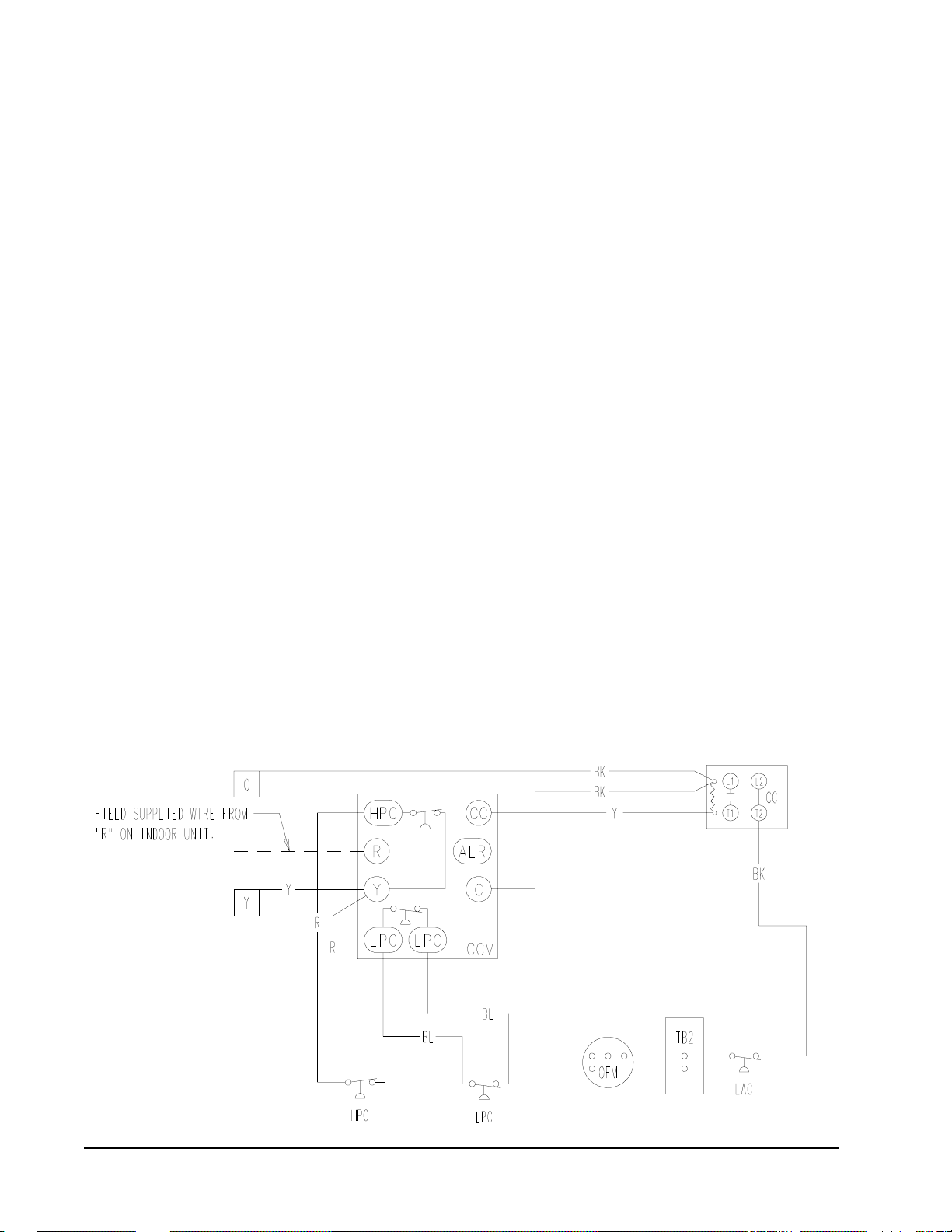
INSTALLATION INSTRUCTIONS – CMA-13A
Disconnect all power to unit. Remove control panel cover.
1. Screw compressor control module and terminal block
into control panel as shown in Figure 5.
2. Disconnect yellow low voltage wire from compressor
contactor and reconnect to terminal “Y” of the
compressor control module.
3. Connect the yellow wire from the compressor control
module to “Y” side of the compressor’s contactor coil.
This is the same terminal from which the wire was
removed in Step 2.
4. Connect the black wire from the compressor control
module to common “C” side of the compressor
contactor coil.
5. Connect a field supplied wire from “R” of the indoor
unit to “R” on the compressor control module.
6. Route the high (red) and low (blue) pressure switch
wires through the bushing in the bottom of the control
panel. Connect the low pressure switch wire to
terminals LPC of the compressor control module.
Connect the high pressure switch wires to terminals
HPC of the compressor control module.
7. Disconnect the high voltage outdoor motor lead and
reconnect to the terminal block installed in Step 1.
8. Route the LAC (black) wires up through the busing in
the bottom of the control panel. Connect one wire to
the terminal block and the other to “T2” of the
contactor. This will be the same terminal from which
the high voltage outdoor motor lead was removed in
Step 7.
9. Remove service port caps on both the suction and
discharge lines. Install the high pressure switch and
the low ambient control on the discharge line with the
flare tee adapter that is brazed to the controls. Install
the low pressure switch on the suction line. Check for
pressure at the flare tee dill valves after installation to
insure that the dill valve in the unit service port was
depressed by the flare tee connector. Check for leaks at
the flare tee connectors. Replace service port caps on
the flare tee service ports and tighten.
10. Adjust the compressor time delay relay to the desired
delay on break. Two minutes are recommended. This
TDR is variable from 30 seconds to 5 minutes.
11. Recheck wiring. Energize unit in first stage cooling.
Compressor should not start until the time delay has
expired. This will be 10% of the delay on break period.
Run the unit for at least 5 minutes. The unit should not
go into lockout. The condenser fan motor should not
run until the discharge pressure has exceeded 300 PSI.
Should the discharge pressure fall below 200 PSI while
running the condenser fan motor will de-energize until
the head pressure builds to 300 PSI.
12. Apply “This unit equipped with CMA-13A control
module.” label to the inside of the inner control panel
cover above the wiring diagram.
13. Replace all panels and covers. This completes
installation.
FIGURE 9
INSTALLATION INSTRUCTIONS FOR
CMA-13A DUAL PRESSURE CONTROL, LOW AMBIENT FAN CYCLING CONTROL
and COMPRESSOR TIME DELAY RELAY
MIS-1304
Manual 2100-346
Page 14
CHARGING INSTRUCTIONS
PRESSURE SERVICE PORTS
High and low pressure service ports are installed on all units
so that the system operating pressures can be observed.
Pressure tables can be found later in the manual covering all
models. It is imperative to match the correct pressure table
to the unit by model number.
SYSTEM START-UP (INDOOR UNITS
WITHOUT EXPANSION VALVES)
1. Close disconnect switch(es) and set the thermostat to
cool and the temperature to the highest setting.
2. Check for proper airflow across the indoor coil by
referring to indoor unit installation.
3. Connect the service gauges and allow the unit to run for
at least 10 minutes or until pressures are stable. Check
pressures to the system pressure table attached to the
outdoor unit service panel. For optimum system
performance, go to Step 4.
4. Install a thermometer on the suction line approximately
6" to 10" from the compressor. Optimum system
performance will occur with a refrigerant charge
resulting in a suction line superheat as determined from
the following calculations.
A. Measure outdoor air dry bulb temperature
________ ºF
B. Measure indoor air wet bulb temperature
________ ºF
C. Measure suction pressure ______PSIG
D. Measure suction line temperature ________ ºF
E. Determine optimum system superheat
from Table 9 using outdoor air dry bulb
(Step B) and indoor air wet bulb (Step A)
________ ºF
TABLE 9
SYSTEM SUPERHEAT
tneibmAroodtuO
F(erutarepmeT
)bluByrD
501
59
09
58
08
57
95367617
1
1
1
3
1
7
3
9
8
41
01
02
bluBteWF
5
)8(
41
91
52
03
TABLE 10
SATURATED SUCTION TEMPERATURE R-22
noitcuSdetarutaS
GISPerusserPnoitcuS
05
35
55
85
16
36
56
76
07
37
67
97
28
68
62
82
03
23
43
63
83
93
14
34
54
74
94
15
)F(erutarepmeT
erutarepmeTriAnruteR
02
62
33
93
24
F. Determine saturated suction temperature
from suction pressure using Table 10 ________ ºF
G. Determine system superheat:
Suction line temperature (Step D) ________ ºF
- Saturated suction temperature (Step F)
- ________ ºF
= System superheat
= ________ ºF
H. Adjust the system superheat (Step G) to the
optimum system superheat (Step E) by adding
charge to lower the superheat or removing
charge to raise the superheat.
I. Check final system operating pressures to the
system pressure tables as was done in Step 3.
Manual 2100-346
Page 15

TABLE 11
TOTAL SYSTEM OPERATING CHARGE
(Includes charge for the basic outdoor unit,
indoor coil and 25’ of interconnecting tubing.)
noitceSroodtuOnoitceSroodnI
A-SA03A
A-181CAH
A-142CAH
A-103CAH
A-163CAH
A-124CAH
B-,A-184CAH
B-,A-106CAH
A-SA42S
B42CB
A-SA03A
A-SA42S
B42CB
A-SA63A
B63CB
A-SA73A
B63CB
A-SA24A
A-SA84A
B63CB
B06CB
A-SA16A
B06CB
A-SA16A
B06CB
.zo37
.zo37
.zo87
.zo08
.zo08
.zo97
.zo48
.zo59
.zo89
.zo69
.zo201
.zo711
.zo501
.zo241
.zo551
.zo571
.zo351
.zo561
SCHEDULE FOR TABLE 11
retemaiDeniLdiuqiL.tFreP22-R.zO
"4/1
"8/3
22-RlatoT
).zO(egrahC
Installer Note: Stamp or mark the final system charge
determined above on the outdoor unit serial plate.
"2/1
52.0
06.0
02.1
Q
R
R
R
R
R
R
Includes 25’ of 1/4” diameter liquid line. For other than 25’ and
Q
other tube sizes, adjust the total charge according to the
following schedule.
Includes 25’ of 3/8” diameter liquid line. For other than 25’ and
R
other tube sizes, adjust the total charge according to the
following schedule.
Manual 2100-346
Page 16

SERVICE
ledoMAnoisnemiDsnoitacoLbuHnaF
181CAH
142CAH
103CAH
163CAH
"5B
124CAH
184CAH
106CAH
"4/3-4C
SERVICE HINTS
1. Caution homeowner to maintain clean air filters at all
times. Also, not to needlessly close off supply and
return air registers. This reduces air flow through the
system, which shortens equipment service life, as well
as, increasing operating costs.
2. Check all power fuses or circuit breakers to be sure that
they are the correct rating.
3. Periodic cleaning of the outdoor coil to permit full and
unrestricted air flow circulation is essential.
FAN BLADE SETTING DIMENSIONS
Shown in Figure 10 are the correct fan blade setting
dimensions for proper air delivery across the outdoor coil.
Any service work requiring removal or adjustment in the fan
and/or motor area will require that the dimensions below be
checked and blade adjusted in or out on the motor shaft
accordingly.
FIGURE 10
FAN BLADE
C
B
A
7960-337
TABLE 12
FAN BLADE SETTING
Manual 2100-346
Page 17

Manual 2100-346
Page 18
Manual 2100-346
Page 19
TABLE 13
PRESSURE TABLE
HAC181-A
roodnI
noitceS
A-SA03SA
A-SA42S
B42CB
Low side pressure ± 2 PSIG (suction line 8 inches from compressor)
High side pressure ± 5 PSIG (discharge line 8 inches from compressor, liquid at base valve approximately -20 PSIG from
values listed)
T ests are based upon rated CFM (airflow) across the evaporator coil. If there is any doubt as to correct operating change being in
the system. The charge should be removed, system evacuated and recharged to serial plate instructions.
riAnruteR
.pmeTerusserP
BD57
BW26
BD08
BW76
BD58
BW27
BD57
BW26
BD08
BW76
BD58
BW27
56075708580959001501011511
ediSwoL
ediShgiH
ediSwoL
ediShgiH
ediSwoL
ediShgiH
ediSwoL
ediShgiH
ediSwoL
ediShgiH
ediSwoL
ediShgiH
86
07
27
47
67
87
08
051
071
781
302
622
442
452
07
37
67
97
18
48
68
961
381
891
312
822
442
062
67
97
28
58
78
09
29
771
191
602
55
26
86
261
871
391
77
87
87
461
081
891
67
97
28
771
191
602
122
632
252
962
37
87
902
422
08
312
032
58
78
122
632
18
48
042
652
18
28
48
642
362
09
29
252
962
lioCroodtuOgniretnEerutarepmeTriA
28
48
58
852
552
642
88
09
29
672
392
013
49
69
89
682
403
223
68
78
78
272
882
403
68
88
09
082
692
313
49
69
89
682
403
223
78
023
39
823
99
043
78
023
39
923
99
043
TABLE 14
PRESSURE TABLE
HAC241-A
roodnI
noitceS
A-SA03SA
A-SA42S
B42CB
Low side pressure ± 2 PSIG (suction line 8 inches from compressor)
High side pressure ± 5 PSIG (discharge line 8 inches from compressor, liquid at base valve approximately -20 PSIG from
values listed)
T ests are based upon rated CFM (airflow) across the evaporator coil. If there is any doubt as to correct operating change being in
the system. The charge should be removed, system evacuated and recharged to serial plate instructions.
riAnruteR
.pmeTerusserP
BD57
BW26
BD08
BW76
BD58
BW27
BD57
BW26
BD08
BW76
BD58
BW27
56075708580959001501011511
ediSwoL
ediShgiH
ediSwoL
ediShgiH
ediSwoL
ediShgiH
ediSwoL
ediShgiH
ediSwoL
ediShgiH
ediSwoL
ediShgiH
06
46
86
17
47
67
87
271
091
702
422
142
852
572
66
07
37
67
97
771
591
312
032
742
37
67
97
28
58
581
302
022
832
752
56
96
37
77
08
971
491
902
522
07
37
57
77
97
401
251
291
522
37
67
97
28
58
581
302
022
832
652
18
38
562
282
78
98
372
28
142
752
152
962
78
372
192
38
372
18
38
082
98
192
lioCroodtuOgniretnEerutarepmeTriA
08
292
58
992
903
48
092
58
482
903
18
28
803
523
68
78
613
333
19
29
49
623
443
58
68
603
423
68
88
182
072
19
29
49
623
443
28
143
88
053
59
263
78
143
98
252
59
263
Manual 2100-346
Page 20

TABLE 15
PRESSURE TABLE
HAC301-A
roodnI
noitceS
A-SA63A
B63CB
Low side pressure ± 2 PSIG (suction line 8 inches from compressor)
High side pressure ± 5 PSIG (discharge line 8 inches from compressor, liquid at base valve approximately -20 PSIG from
values listed)
T ests are based upon rated CFM (airflow) across the evaporator coil. If there is any doubt as to correct operating change being in
the system. The charge should be removed, system evacuated and recharged to serial plate instructions.
riAnruteR
.pmeTerusserP
BD57
BW26
BD08
BW76
BD58
BW27
BD57
BW26
BD08
BW76
BD58
BW27
56075708580959001501011511
ediSwoL
ediShgiH
ediSwoL
ediShgiH
ediSwoL
ediShgiH
ediSwoL
ediShgiH
ediSwoL
ediShgiH
ediSwoL
ediShgiH
26
56
76
96
261
381
402
422
86
07
27
47
761
881
012
032
57
77
87
08
171
491
612
832
16
56
96
27
581
76
091
47
891
102
712
432
17
47
77
702
322
932
77
08
38
512
232
842
17
37
57
442
262
082
67
87
08
052
962
782
28
48
68
852
872
792
57
77
97
052
662
282
08
28
48
652
272
982
68
88
09
562
282
992
lioCroodtuOgniretnEerutarepmeTriA
77
87
08
792
313
923
28
48
58
503
88
513
892
68
603
29
613
123
833
09
29
333
943
18
28
38
413
78
223
39
333
133
88
933
59
153
TABLE 16
PRESSURE TABLE
HAC361-A
18
443
78
353
49
563
48
743
98
653
69
863
roodnI
noitceS
A-SA73A
B63CB
Low side pressure ± 2 PSIG (suction line 8 inches from compressor)
High side pressure ± 5 PSIG (discharge line 8 inches from compressor, liquid at base valve approximately -20 PSIG from
values listed)
T ests are based upon rated CFM (airflow) across the evaporator coil. If there is any doubt as to correct operating change being in
the system. The charge should be removed, system evacuated and recharged to serial plate instructions.
riAnruteR
.pmeTerusserP
BD57
BW26
BD08
BW76
BD58
BW27
BD57
BW26
BD08
BW76
BD58
BW27
56075708580959001501011511
ediSwoL
ediShgiH
ediSwoL
ediShgiH
ediSwoL
ediShgiH
ediSwoL
ediShgiH
ediSwoL
ediShgiH
ediSwoL
ediShgiH
66
86
07
27
47
67
87
181
791
312
032
642
262
872
17
37
57
77
97
18
38
681
202
912
532
252
862
582
77
97
191
802
36
66
871
591
66
96
481
002
27
57
881
602
18
38
58
78
98
622
342
062
872
592
86
07
27
47
67
212
822
542
262
972
27
57
87
08
28
712
432
152
962
682
87
422
18
38
68
88
242
062
872
692
lioCroodtuOgniretnEerutarepmeTriA
08
28
48
492
013
623
58
78
98
203
813
533
19
39
59
213
033
743
87
97
18
692
313
133
48
58
78
403
09
413
123
933
29
49
233
153
68
343
19
153
79
463
28
843
88
753
59
963
Manual 2100-346
Page 21

TABLE 17
PRESSURE TABLE
HAC 421-A
roodnI
noitceS
A-SA24A
B63CB
A-SA84A
B06CB
Low side pressure ± 2 PSIG (suction line 8 inches from compressor)
High side pressure ± 5 PSIG (discharge line 8 inches from compressor, liquid at base valve approximately -20 PSIG from
values listed)
T ests are based upon rated CFM (airflow) across the evaporator coil. If there is any doubt as to correct operating change
being in the system. The charge should be removed, system evacuated and recharged to serial plate instructions.
riAnruteR
.pmeTerusserP
BD57
BW26
BD08
BW76
BD58
BW27
BD57
BW26
BD08
BW76
BD58
BW27
5708580959001501011511
ediSwoL
ediShgiH
ediSwoL
ediShgiH
ediSwoL
ediShgiH
ediSwoL
ediShgiH
ediSwoL
ediShgiH
ediSwoL
ediShgiH
46
302
96
802
37
612
37
212
77
812
38
422
76
812
27
422
77
232
47
822
97
432
58
142
07
332
57
042
08
842
67
442
18
052
78
852
27
052
77
652
38
562
77
062
38
762
98
672
47
662
97
372
58
282
97
772
58
482
19
492
67
382
28
092
78
003
18
492
78
203
39
492
lioCroodtuOgniretnEerutarepmeTriA
77
003
28
803
98
813
28
213
98
023
59
133
87
813
48
623
09
733
48
033
09
933
79
053
TABLE 18
PRESSURE TABLE
HAC481-A, HAC481-B
97
633
58
543
19
953
68
943
29
853
99
073
roodnI
noitceS
-SA16A
B
B06CB
Low side pressure ± 2 PSIG (suction line 8 inches from compressor)
High side pressure ± 5 PSIG (discharge line 8 inches from compressor, liquid at base valve approximately -20 PSIG from
values listed)
T ests are based upon rated CFM (airflow) across the evaporator coil. If there is any doubt as to correct operating change
being in the system. The charge should be removed, system evacuated and recharged to serial plate instructions.
riAnruteR
.pmeTerusserP
BD57
BW26
BD08
BW76
BD58
BW27
BD57
BW26
BD08
BW76
BD58
BW27
5708580959001501011511
ediSwoL
ediShgiH
ediSwoL
ediShgiH
ediSwoL
ediShgiH
ediSwoL
ediShgiH
ediSwoL
ediShgiH
ediSwoL
ediShgiH
47
802
87
412
48
022
86
242
67
842
28
752
57
322
08
922
68
632
07
052
77
652
38
562
77
832
28
542
88
352
27
062
87
662
48
672
87
452
48
162
09
072
47
272
08
872
68
882
08
172
68
872
29
882
67
582
18
292
78
203
28
882
88
692
49
603
87
003
28
803
88
813
lioCroodtuOgniretnEerutarepmeTriA
38
603
09
413
69
523
97
713
48
523
09
633
58
423
19
333
79
443
08
633
58
443
19
653
78
343
39
253
99
463
18
653
78
563
39
873
Manual 2100-346
Page 22

TABLE 19
PRESSURE TABLE
HAC601-A, HAC601-B
roodnI
noitceS
-SA16A
B
B06CB
Low side pressure ± 2 PSIG (suction line 8 inches from compressor)
High side pressure ± 5 PSIG (discharge line 8 inches from compressor, liquid at base valve approximately -20 PSIG from
values listed)
T ests are based upon rated CFM (airflow) across the evaporator coil. If there is any doubt as to correct operating change
being in the system. The charge should be removed, system evacuated and recharged to serial plate instructions.
riAnruteR
.pmeTerusserP
BD57
BW26
BD08
BW76
BD58
BW27
BD57
BW26
BD08
BW76
BD58
BW27
5708580959001501011511
ediSwoL
ediShgiH
ediSwoL
ediShgiH
ediSwoL
ediShgiH
ediSwoL
ediShgiH
ediSwoL
ediShgiH
ediSwoL
ediShgiH
76
722
27
232
87
042
46
322
96
032
67
732
96
342
47
942
08
852
76
932
27
642
87
552
17
062
67
662
28
672
07
752
57
462
08
372
37
672
87
482
48
392
27
572
77
382
28
392
57
392
08
103
68
113
47
592
97
303
58
413
67
013
28
813
88
923
67
613
18
523
58
633
lioCroodtuOgniretnEerutarepmeTriA
87
623
48
633
09
643
77
933
28
843
78
063
97
343
68
353
29
463
87
363
38
273
98
583
97
953
88
073
49
283
87
883
48
893
09
114
Manual 2100-346
Page 23
 Loading...