

Page 1
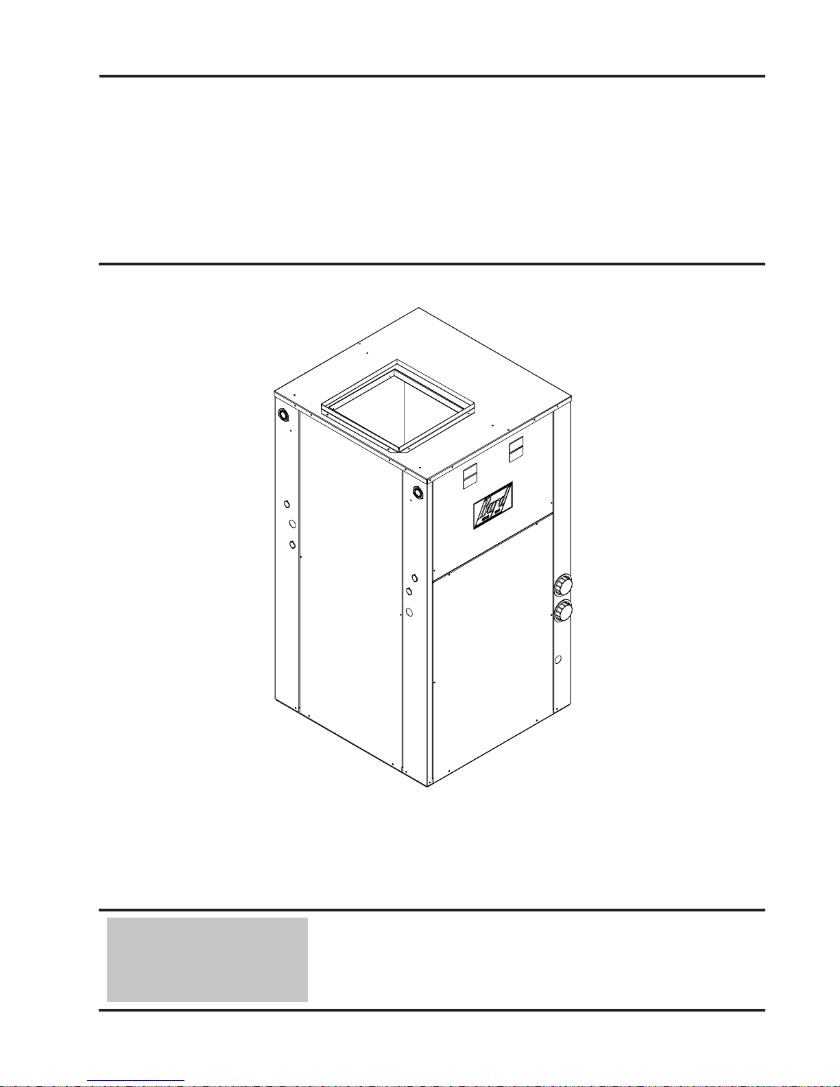
INSTALLATION
INSTRUCTIONS
WATER SOURCE
HEAT PUMPS
Models:
GV27S1-A, GV38S1-A
GV51S1-A, GV61S1-A
GV71S1-A
Ground Water Temperatures 45° - 75°
MIS-2615
Earth Loop Fluid
Temperatures 25° - 110°
Bard Manufacturing Company, Inc.
Bryan, Ohio 43506
Since 1914...Moving ahead, just as planned.
Manual: 2100-510E
Supersedes: 2100-510D
File: Volume I, Tab 8
Date: 08-04-09
Manual 2100-510E
Page 1 of 38
Page 2

CONTENTS
Getting Other Informations and Publications ........ 3
General Information
Water Source Nomenclature ................................... 4
Heater Package Nomenclature ............................... 8
Application and Location
General ................................................................ 9
Shipping Damage .................................................... 9
Application ............................................................... 9
Location ................................................................ 9
Ductwork ................................................................ 9
Filters ............................................................... 11
Condensate Drain ................................................... 11
Piping Access to Unit..............................................11
Wiring Instructions
General .............................................................. 14
Control Circuit Wiring ............................................ 14
Wall Thermostats................................................... 14
Thermostat Indicators ............................................ 14
Emergency Heat Mode .......................................... 14
Ground Loop (Earth Coupled Water Loop Applications)
Note .............................................................. 16
Circulation System Design .................................... 16
Start Up Procedure for Ground Loop System ........ 17
Ground Water (Well System Applications)
Note .............................................................. 19
Water Connections ................................................ 19
Well Pump Sizing .......................................... 19 & 20
Start Up Procedure for Ground Water System ...... 21
Water Corrosion ............................................ 21 & 22
Remedies of Water Problems................................ 22
Lake and/or Pond Installations ...................... 22 & 23
Sequence of Operation
Blower .............................................................. 24
Part Load Cooling .................................................. 24
Full Load Cooling ................................................... 24
Part Load Heating .................................................. 24
Full Load Heating .................................................. 24
Supplementary Electric Heat ................................. 24
Emergency Heat Mode .......................................... 24
Compressor Control Module .................................. 25
Pressure Service Ports .......................................... 25
System Start Up..................................................... 25
Pressure Tables ............................................. 28 & 29
Quick Reference Troubleshooting Chart ............... 30
Service
Service Hints ......................................................... 31
Unbrazing System Components ............................ 31
Compressor Solenoid ............................................ 31
Troubleshooting GE X13-Series Motors ........ 32 & 33
Accessories
Add-On GVDM-26 Pump Module Kit ..................... 34
General .............................................................. 34
Installation ............................................................. 34
Ground Source Heat Pump
Performance Report .......................................... 35-36
Wiring Diagrams ................................................ 37-38
Figures
Figure 1 Unit Dimensions ...................................... 7
Figure 2 Field-Conversion to Left Hand Return .. 10
Figure 3 Filter Rack Configuration ...................... 12
Figure 4 Piping Access ....................................... 13
Figure 5 Thermostat Wiring ................................ 15
Figure 6 Circulation System Design .................... 16
Figure 7 Temperature & Pressure Measurement ... 18
Figure 8 Model DORFC-1 Flow Center ............... 18
Figure 9 Model DORFC-2 Flow Center ............... 18
Figure 10 Water Connection Components ............ 20
Figure 11 Cleaning Water Coil .............................. 22
Figure 12 Lake or Pond Installation ...................... 23
Figure 13 Component Location ............................. 26
Figure 14 Control Panel ........................................ 26
Figure 15 Refrigerant Flow Diagrams ................... 27
Figure 16A Pressure Tables ....................................... 28
Figure 16B Pressure Tables ....................................... 29
Figure 17 Motor Connections ................................ 32
Figure 18 Motor Connections ................................ 33
Figure 19 Typical Pump Kit Connection ................ 34
Manual 2100-510E
Page 2 of 38
Tables
Table 1 Indoor Blower Performance .................... 4
Table 2 Flow Rates for Various Fluids ................. 5
Table 3 Specifications .......................................... 5
Table 4 Water Coil Pressure Drop ....................... 6
Table 5 Electrical Specifications Optional Field
Installed Heater Package ........................ 8
Table Air Filter Table ........................................11
Table 6 Control Circuit Wiring ............................ 14
Table 7 Wall Thermostat .................................... 14
Table 8 Constant Flow Valves ........................... 19
Page 3

GETTING OTHER INFORMATION AND PUBLICATIONS
These publications can help you install the air
conditioner or heat pump. You can usually find these at
your local library or purchase them directly from the
publisher. Be sure to consult current edition of each
standard.
National Electrical Code ...................... ANSI/NFPA 70
Standard for the Installation .............. ANSI/NFPA 90A
of Air Conditioning and Ventilating Systems
Standard for Warm Air ...................... ANSI/NFPA 90B
Heating and Air Conditioning Systems
Load Calculation for Residential ....... ACCA Manual J
Winter and Summer Air Conditioning
Duct Design for Residential ............. ACCA Manual D
Winter and Summer Air Conditioning and Equipment
Selection
Closed-Loop/Ground Source Heat Pump ........ IGSHPA
Systems Installation Guide
Grouting Procedures for Ground-Source ......... IGSHPA
Heat Pump Systems
Soil and Rock Classification for ...................... IGSHPA
the Design of Ground-Coupled Heat Pump Systems
Ground Source Installation Standards ............. IGSHPA
Closed-Loop Geothermal Systems .................. IGSHPA
– Slinky Installation Guide
FOR MORE INFORMATION, CONTACT
THESE PUBLISHERS:
ACCA Air Conditioning Contractors of America
1712 New Hampshire Avenue
Washington, DC 20009
Telephone: (202) 483-9370
Fax: (202) 234-4721
ANSI American National Standards Institute
11 West Street, 13th Floor
New York, NY 10036
Telephone: (212) 642-4900
Fax: (212) 302-1286
ASHRAE American Society of Heating Refrigerating,
and Air Conditioning Engineers, Inc.
1791 Tullie Circle, N.E.
Atlanta, GA 30329-2305
Telephone: (404) 636-8400
Fax: (404) 321-5478
NFPA National Fire Protection Association
Batterymarch Park
P.O. Box 9101
Quincy, MA 02269-9901
Telephone: (800) 344-3555
Fax: (617) 984-7057
IGSHPA International Ground Source
Heat Pump Association
490 Cordell South
Stillwater, OK 74078-8018
Manual 2100-510E
Page 3 of 38
Page 4
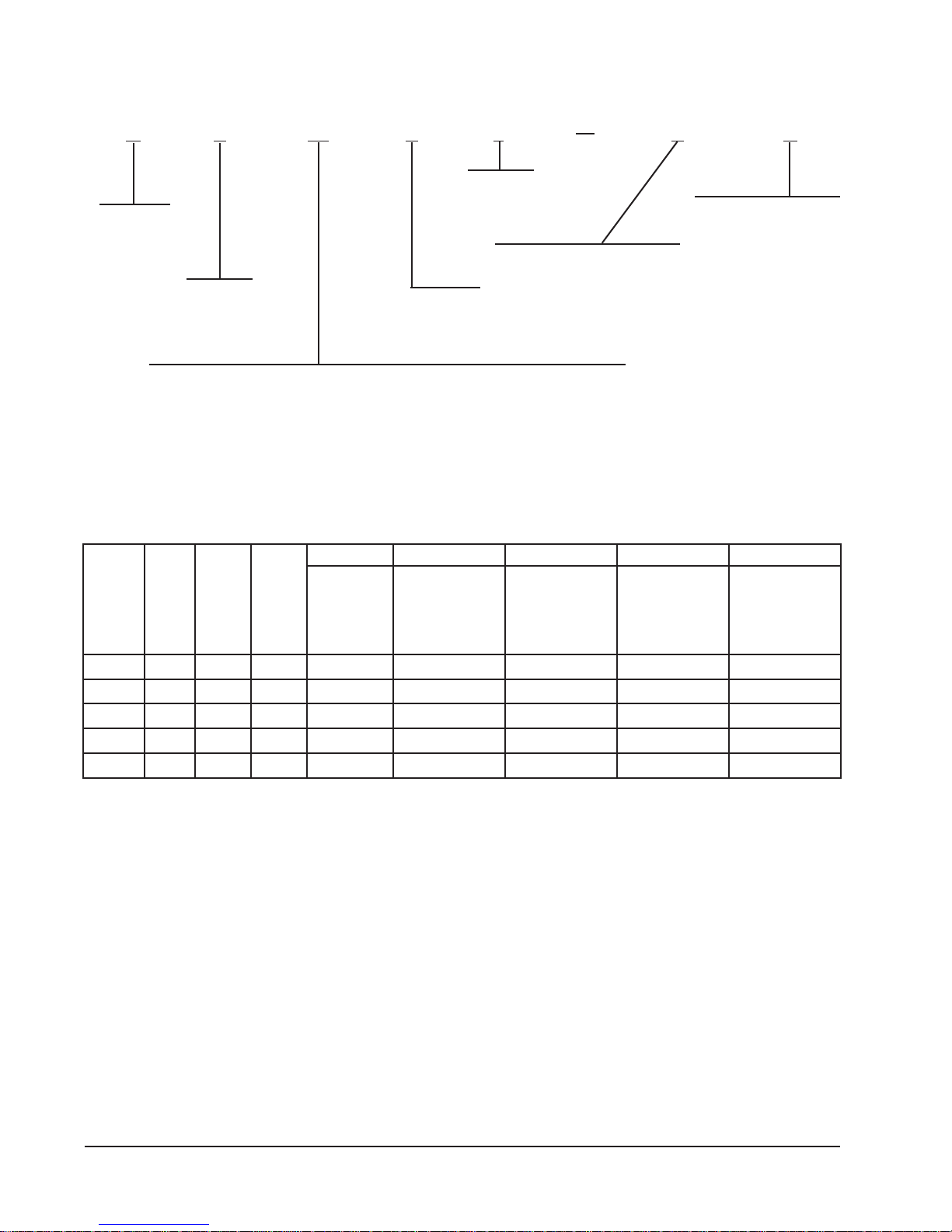
WATER SOURCE PRODUCT LINE NOMENCLATURE
G V 38 S 1 A C
Revision
Level
Ground
Source
Electrical 230/208V 1-Phase
C = Copper Water Coil
N = Cupronickel
Vertical
Step
Capacity
38 = Nominal heating capacity in thousands @ 50° water - Full Load
Nominal cooling capacity in thousands @ 77° brine - Full Load
TABLE 1
INDOOR BLOWER PERFORMANCE (RATED CFM)
1#deepS2#deepS3#deepS4#deepS5#deepS
2
LEDOM
1S72VG3/151.005.00050560080090001
1S83VG2/151.005.005652700957110031
1S15VG2/102.005.0057529051105310051
1S16VG4/302.005.00080501003105410061
1S17VG4/352.005.05780511054157510571
rotoM
PH
3
detaR
PSE
XAM
PSE
4
suounitnoC
wolfriA
5
rehtaeWdliM
ts
1ninoitarepO
gnilooCegatS
).niM-5(edoM
6
daoLtraP
noitarepO
wolfriA
1
7
daoLlluF%01-
wolfriA
)lanoitpO(
8
daoLlluF
dnawolfriA
taeHcirtcelE
edoM
1 Motor will automatically step through the various airflows with thermostatic control
2 ESP = External Static Pressure (inches of water)
3 Maximum allowable duct static
4 Continuous airflow is the CFM being circulated with manual fan operation without any additional function occurring.
5 Will occur automatically for first 5 minutes of Part Load Cooling Operation.
6 Will occur automatically after five minutes of Part Load Cooling Operation.
7 This is a field option for noisy installations to de-rate Full Load airflow (requires change in control panel).
8 Will occur automatically with control signal input (will not be defeated for electric heat operation).
Manual 2100-510E
Page 4 of 38
Page 5
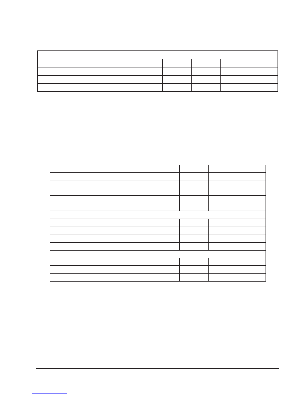
TABLE 2
FLOW RATES FOR VARIOUS FLUIDS
SDIULFSUOIRAV
retawhserfMPGderiuqeretarwolF 1 5679 01
edirolhCmuidoS%51MPGderiuqeretarwolF7
4SG%52MPGderiuqeretarwolF79215161
1 Rated Flow
TABLE 3
SPECIFICATIONS
LEDOM*A-1S72VG*A-1S83VG*A-1S15VG*A-1S16VG*A-1S17VG
)HP1/ZH06(gnitaRlacirtcelE1-802/0321-802/0321-802/0321-802/0321-802/032
egnaRegatloVgnitarepO791-352791-352791-352791-352791-352
yticapmAtiucriCmuminiM 1 7162238314
eziSeriWdleiF+ 1 21#01#8#6#6#
.rkB.tkCro.xaMesuFyaleD++ 1 0203040505
ROSSERPMOC
stloV802/032802/032802/032802/032802/032
802/032spmAdaoLdetaR1.01/4.85.41/4.216.02/4.714.72/4.225.82/7.42
tnerruCnoitceleS.tkChcnarB2.017.612.124.725.82
802/032spmArotoRkcoL26/2628/2869/69811/811051/051
ROTAROPAVEDNAROTOMREWOLB
epyT/deepS/PH-rotoMrewolBMCE/5/3/1MCE/5/2/1MCE/5/2/1MCE/5/4/3MCE/5/4/3
spmA-rotoMrewolB6.1/5.159.2/5.20.3/8.21.4/8.32.4/1.4
hcnIrePsniF/woR/.tF.qSaerAecaF11/4/61.311/4/61.311/3/33.511/4/33.501/5/33.5
+75°C copper wire ++ HACR type circuit breaker
* C - for copper / N for Cupro-Nickel water coil
1 Heat pump only. Optional field-installed heaters are separate circuit.
SLEDOM
S72VGS83VGS15VGS16VGS17VG
9215161
Manual 2100-510E
Page 5 of 38
Page 6
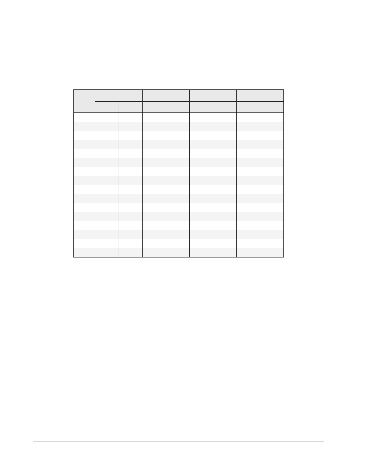
TABLE 4
WATER COIL PRESSURE DROP
ledoM
MPG
31.032.0
4 5.0 51.1 9.0 80.2
52.177.24.132.3
6 7.1 29.3 3.2 13.5
73.213.52.383.7216.4
8 1.3 51.7 1.4 64.9 5.2 77.5 2 16.4
91.464.91.577.112.383.74.245.5
01 1.6 70.41 9.3 00.9 8.2 64.6
111.783.617.448.014.348.7
21 2.8 29.81 5.5 96.21 9.3 00.9
314.996.124.667.415.483.01
41 6.01 54.42 3.7 48.61 2.5 00.21
511.896.819.516.31
61 9 67.02 7.6 64.51
719.948.224.770.71
81 4.8 83.91
1S72VG 1S15VG/1S83VG 1S16VG 1S17VG
DISP .dH.tF DISP .dH.tF DISP .dH.tF DISP .dH.tF
Manual 2100-510E
Page 6 of 38
Page 7

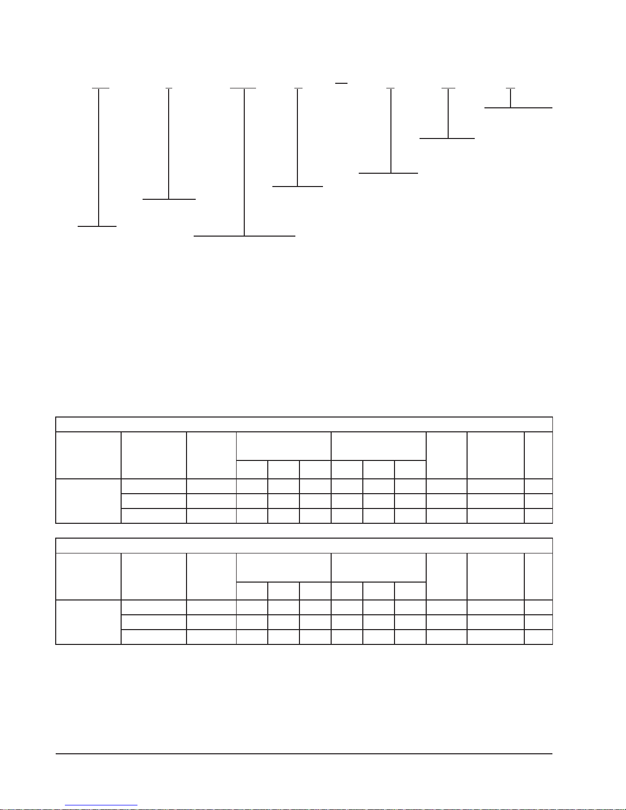
BACK VIEW
Y
MIS-2616
X
W
U
V
FIGURE 1 – UNIT DIMENSIONS
61/7-22/1-18/7-254/1-238/5-12/1-22/1-34/3-9261/31-6261/1-861/5-9161/5-5161/1-28/7-98/5-5261/7-0361/5-1
FILTER RACK
RETURN AIR
I
B
E
RIGHT SIDE VIEW
SUPPLY AIR
J
OPTIONAL
H
HEATER
PACKAGE
ELECTRICAL
LOW
VOLTAGE
G
NOTE A
SEE
VOLTAGE
LOW
ENTRANCE
Y
ENTRANCE
WATER CONNECTIONS
DOMESTIC HOT WATER
HEAT EXCHANGER
C
ENTRANCE
FLOW CENTER
ELECTRICAL
ENTRANCE
DRAIN LOCATION
CONDENSATE
S
NOTE A
SEE
UNIT
ELECTRICAL
ENTRANCE
R
T
R
WATER
CONNECTIONS
CONDENSATE
DRAIN LOCATION
F
TOP VIEW
ylppuSnruteR
tcuDegnalFhtdiWthgieH
8/5-7262848/7-318/7-31814/3-228/7-661/7-22/1-14/1-548/5-138/5-14/1-24/1-361/1-9261/31-5261/3-82/1-912/1-5161/1-28/3-78/1-3261/7-524/1-1
htdiWhtpeDthgieH
8/5-23728/5-558/7-718/7-712/1-328/7-927
ABCDE FGHIJKLMNOP Q RS T UVWXY
1S83-72VG
1S17-15VG
stinU
D
A
FRONT VIEW
LEFT SIDE VIEW
N
M
G
SEE
NOTE A
C
O
Q
P
L
K
R
T
S
NOTE A: PANELS ARE REVERSIBLE ALONG WITH
CONTROL PANELS FOR HEAT PUMP AND
ELECTRIC HEATER PACKAGE FOR BEST
INSTALLATION POSITION.
WATER
CONNECTIONS
CONDENSATE
DRAIN LOCATION
Manual 2100-510E
Page 7 of 38
Page 8
HEATER PACKAGE NOMENCLATURE
EH 3 GSV A A 14 C
3 = 3 Ton
5 = 5 Ton
Electric
Heater
Ground Source Vertical
Circuit Breaker
Nominal KW
240/208-1-60
Modification
Code
TABLE 5
ELECTRICAL SPECIFICATIONS
segakcaPretaeHdellatsnI-dleiFlanoitpO-snoitacificepSlacirtcelE
esUroF
sledoMhtiw
A-1S72VG
&
A-1S83VG
esUroF
sledoMhtiw
A-1S15VG
A-1S16VG
&
A-1S17VG
+ Based on 75F copper wire. All wiring must conform to National Electrical Code (latest edition) and all local codes.
retaeH
egakcaP
.oNledoM
C50A-AVSG3HE1-802/0428.815.4543,513.6183.3525,115.325201
C90A-AVSG3HE1-802/0425.730.9096,035.2357.6810,329.64058
C41A-AVSG3HE1-802/0423.655.31530,647.8431.01345,434.07084
retaeH
egakcaP
.oNledoM
C90A-AVSG5HE1-802/0425.730.9096,035.2357.6810,329.64058
C41A-AVSG5HE1-802/0423.655.31530,647.8431.01345,434.07084
C81A-AVSG5HE1-802/0420.570.81083,169.465.31530,643.890013
retaeH
egakcaP
esahP/stloV
ZH06
retaeH
egakcaP
ZH06
SPMAWKUTBSPMAWKUTB
esahP/stloV
SPMAWKUTBSPMAWKUTB
dnaWK,spmAretaeH
stloV042@yticapaC
segakcaPretaeHdellatsnI-dleiFlanoitpO-snoitacificepSlacirtcelE
dnaWK,spmAretaeH
stloV042@yticapaC
dnaWK,spmAretaeH
stloV802@yticapaC
dnaWK,spmAretaeH
stloV802@yticapaC
muminiM
tiucriC
yticapmA
muminiM
tiucriC
yticapmA
mumixaM
RCAH
tiucriC
rekaerB
mumixaM
RCAH
tiucriC
rekaerB
dleiF
eriW
+eziS
dleiF
eriW
+eziS
Manual 2100-510E
Page 8 of 38
Page 9

APPLICATION AND LOCATION
GENERAL
Units are shipped completely assembled and internally
wired, requiring only duct connections, thermostat wiring,
230/208 volt AC power wiring, and water piping. The
equipment covered in this manual is to be installed by
trained, experienced service and installation technicians.
These instructions and any instructions packaged with any
separate equipment required to make up the entire heat
pump system should be carefully read before beginning the
installation. Note particularly any tags and/or labels
attached to the equipment.
While these instructions are intended as a general
recommended guide, they do not in any way supersede any
national and/or local codes. Authorities having jurisdiction
should be consulted before the installation is made.
SHIPPING DAMAGE
Upon receipt of the equipment, the carton should be
checked for external signs of shipping damage. If damage
is found, the receiving party must contact the last carrier
immediately, preferably in writing, requesting inspection
by the carrier’s agent.
APPLICATION
Capacity of the unit for a proposed installation should be
based on heat loss calculations made in accordance with
methods of the Air Conditioning Contractors of America.
The air duct system should be sized and installed in
accordance with Standards of the National Fire Protection
Association for the Installation of Air Conditioning and
Venting systems of Other than Residence Type NFPA No.
90A, and residence Type Warm Air Heating and Air
Conditioning Systems, NFPA No. 90B.
Unit casing suitable for 0 inch clearance with 1-inch duct
clearance for at least the first 3 feet of duct. These units
are not approved for outdoor installation and therefore
must be installed inside the structure being conditioned.
Do not locate in areas subject to freezing in the winter or
subject to sweating in the summer.
Before setting the unit, consider ease of piping, drain and
electrical connections for the unit. Also, for units which
will be used with a field installed heat recovery unit,
consider the proximity of the unit to the water heater or
storage tank. Place the unit on a solid base, preferably
concrete, to minimize undesirable noise and vibration. DO
NOT elevate the base pan on rubber or cork vibration
eliminator pads as this will permit the unit base to act like a
drum, transmitting objectionable noise.
DUCTWORK
If the unit is to be installed in a closet or utility room which
does not have a floor drain, a secondary drain pan under
the entire unit is highly recommended.
DO NOT install the unit in such a way that a direct path
exists between any return grille and the unit. Rather, insure
that the air entering the return grille will make at least one
turn before entering the unit or coil. This will reduce
possible objectionable compressor and air noise from
entering the occupied space.
Design the ductwork according to methods given by the Air
Conditioning Contractors of America. When duct runs
through unconditioned spaces, it should be insulated with
vapor barrier. It is recommended that flexible connections
be used to connect the ductwork to the unit in order to keep
the noise transmission to a minimum.
LOCATION
The unit may be installed in a basement, closet, or utility
room provided adequate service access is insured. The unit
is shipped from the factory as a right hand return and
requires access clearance of two feet minimum to the
access panels on this side of the unit. If unit is to be field
converted to left hand return the opposite side will require
access clearance of two feet minimum.
Unit may be field converted to left hand return by
removing two (2) screws that secure the control panel
cover, removing four (4) screws that hold the control panel
in place, laying the control panel down, sliding it under the
blower and re-securing the control panel on the opposite
side of the unit. (See Figure 2.) The two (2) access doors
from the right hand return can be transferred to the lefthand return side and the one (1) left-hand panel can be
transferred to the right hand side.
WARNING
Failure to provide the 1-inch clearance
between the supply duct and a combustible
surface for the first 3 feet of duct can result in
a fire.
Manual 2100-510E
Page 9 of 38
Page 10
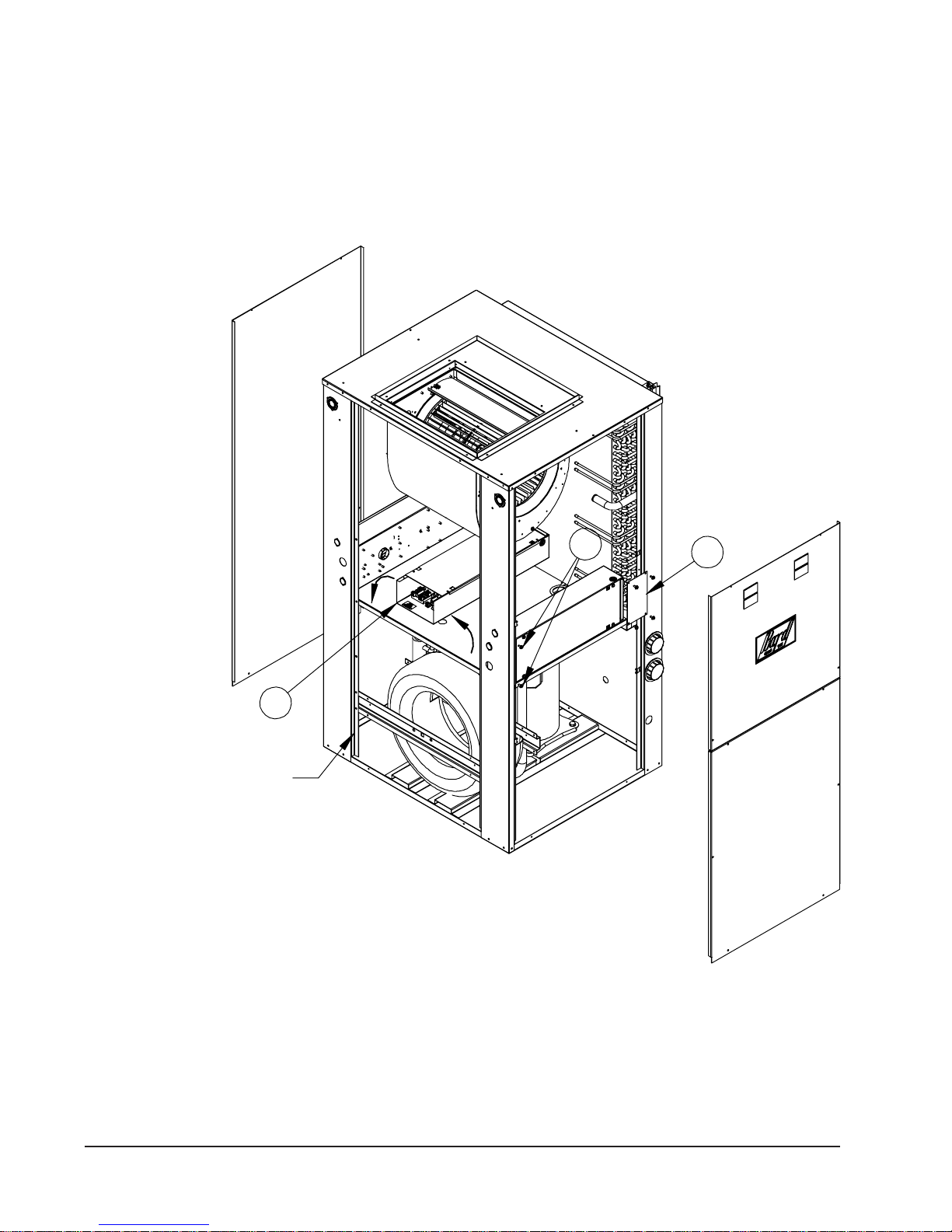
FIGURE 2
FIELD-CONVERSION TO LEFT HAND RETURN
3
Panel removed for clarity.
Does not need removed
to change control panel location.
1. Remove control panel fill plate.
2. Remove two screws securing control panel to unit.
3. Pass control panel through blower section rotating 180°.
4. Re-secure control panel on opposite si de in same manner
as original ly attached.
5. Move double doors t o control panel side of unit.
2
MIS-2617
1
Manual 2100-510E
Page 10 of 38
Page 11

FILTER
This unit must not be operated without a filter. It comes
equipped with 2" disposable filters, which should be
checked often and replaced if dirty. Insufficient airflow
due to undersized duct systems or dirty filters can result in
nuisance tripping of the high or low pressure controls.
Refer to Table 2 for correct airflow and static pressure
requirements.
NOTE: The filter rack is installed on the unit as shipped
for right-hand return. If you require left-hand return, you
will need to remove the filter access door and remove the
screws holding the filter rack to the unit (slide downward
from underneath unit top). Invert the filter rack 180° to
move filter access door to the other side of the unit, and
reverse the previous steps (see Figure 3).
CONDENSATE DRAIN
Drain lines must be installed according to local plumbing
codes. It is not recommended that any condensate drain
line be connected to a sewer main.
Determine where the drain line will run and then select one
of four (4) locations for the condensate to exit the unit
casing (see Figure 4). There are knockouts in the unit
casing that can be selected for the condensate exit. Internal
of the unit, there is a clear flexible hose with a termination
fitting installed. When installed properly, this hose will
create a trap internal of the unit and will remain serviceable
if the drain system requires cleaning or service. Supplied in
the parts bag of the unit is a 3/4" PVC male adaptor that
will secure the internal drain components to the sheet metal
casing at the location you selected.
NOTE: You will need to bend the duct attachment flanges
up using duct bills or similar device, as the unit is shipped
with them collapsed.
AIR FILTERS
ledoMeziSretliFytitnauQ
S72VG
S83VG
S15VG
S16VG
S17VG
"2x"52x"021
"2x"52x"612
NOTE: This drain line will contain cold water and must be
insulated to avoid droplets of water from condensing on the
pipe and dripping on finished floors or the ceiling below
the unit.
PIPING ACCESS TO UNIT
Water piping to and from the unit enters the unit cabinet on
either side of the unit. The connection directly at the unit is
a special double o-ring fitting with a retainer nut that secures
it in place. (It is the same style fitting used for the flow
center connection on ground loop applications.) You may
come in and out either side of the unit in any combination as
the installation dictates. One side has both connections
closed off with a double o-ring plug seal with retaining caps.
One or both of these are transferred to opposite side depending upon installation requirements.
Note: All double o-ring fittings require “hand tightening
only”. Do not use wrench or pliers as retainer nut can be
damaged with excessive force.
Various fittings are available so you may then connect to
the unit with various materials and methods. These
methods include 1" barbed fittings (straight and 90°), 1"
MPT (straight and 90°), and 1-1/4" hot fusion fitting
(straight only) (see Figures 3 & 4).
Manual 2100-510E
Page 11 of 38
Page 12
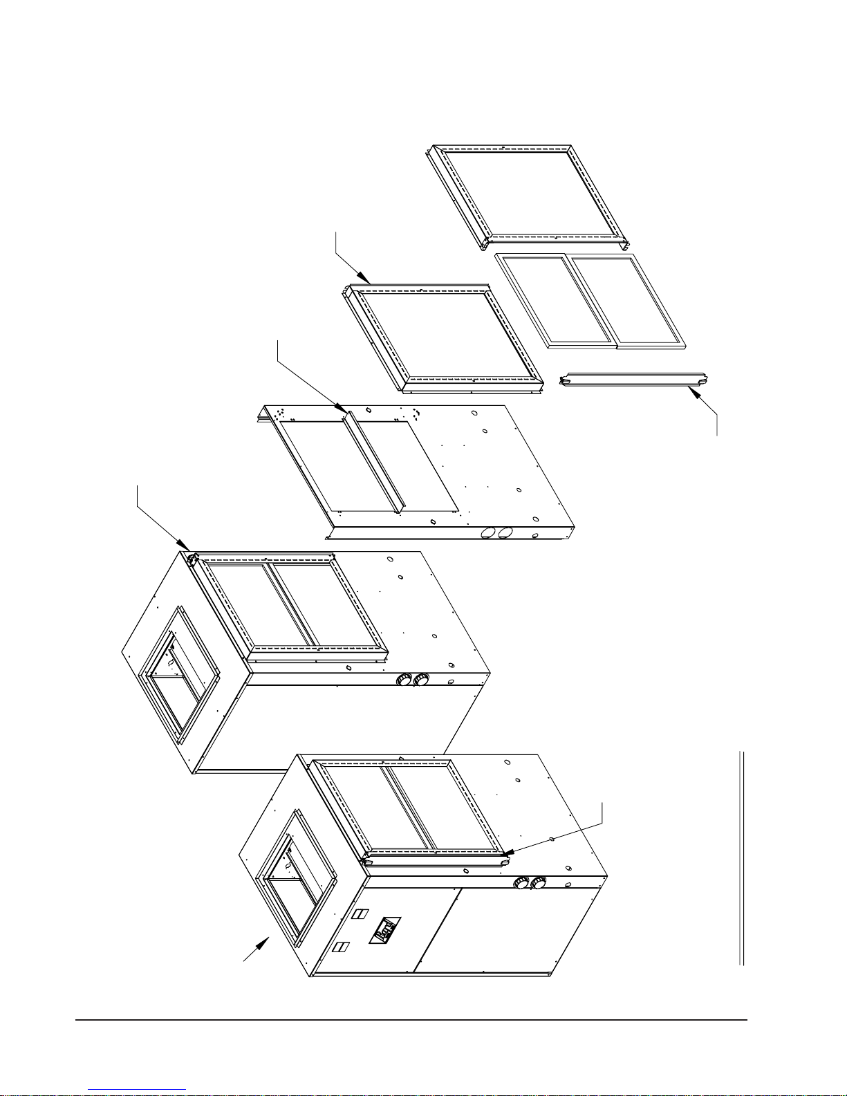
frame 180°
to unit. Rotate filter rack
holding fi lter rack frame
Remove all screws
rack install ed.
Left-hand access filter
FIGURE 3
FILTER RACK – GV MODELS
install ed location.
does not need to be rotat ed. Leave in factory
Filter rack channel on GV51S1,61S1,71S1
MIS-2618
first r em ove filter rack door and filters.
To convert filter rack to left -hand access
Front of Unit
Manual 2100-510E
Page 12 of 38
Filter rack shipped for
right-hand access f rom factory.
Drawing show s dual air filter
models GV51S1,61S1,71S1.
GV27S1,38S 1 have only one air filt er.
Page 13

FIGURE 4
CONDENSATE DRAIN & PIPING ACCESS TO UNIT
Water in connection
Water out connection
Condensate drain
access (4) locations
MIS-2619
Desuperheater
Pump module connections
1/2" I.D. copper stub
Manual 2100-510E
Page 13 of 38
Page 14

WIRING INSTRUCTIONS
GENERAL
All wiring must be installed in accordance with the
National Electrical Code and local codes. In Canada, all
wiring must be installed in accordance with the Canadian
Electrical Code and in accordance with the regulations of
the authorities having jurisdiction. Power supply voltage
must conform to the voltage shown on the unit serial plate.
A wiring diagram of the unit is attached to the inside of the
electrical cover. The power supply shall be sized and fused
according to the specifications supplied. A ground lug is
supplied in the control compartment for equipment ground.
The unit rating plate lists a “Maximum Time Delay Fuse”
or “HACR” type circuit breaker that is to be used with the
equipment. The correct size must be used for proper
circuit protection and also to assure that there will be no
nuisance tripping due to the momentary high starting
current of the compressor motor.
CONTROL CIRCUIT WIRING
The minimum control circuit wiring gauge needed to insure
proper operation of all controls in the unit will depend on
two factors.
1. The rated VA of the control circuit transformer.
2. The maximum total distance of the control circuit
wiring.
Table 6 should be used to determine proper gauge of
control circuit wiring required.
TABLE 6
CONTROL CIRCUIT WIRING
foAVdetaR
tiucriClortnoC
remrofsnarT
051.2
Example: 1. Control Circuit transformer rated at 50 VA
2. Maximum total distance of control circuit
wiring 85 feet.
From Table 6 minimum of 16 gauge wire
should be used in the control circuit wiring.
remrofsnarT
yradnoceS
V42@ALF
foecnatsiD
WALL THERMOSTAT
The following thermostat should be used as indicated,
depending on the application.
TABLE 7
WALL THERMOSTAT
tatsomrehTserutaeFtnanimoderP
taeHegats3;looCegats3
060-3048
)544-0211(
lanoitnevnoCroPH
revoegnahclaunaMrootuA
latoTmumixaM
tiucriClortnoC
teeFnigniriW
54-eguag02
06-eguag81
001-eguag61
061-eguag41
052-eguag21
cinortcelEelbammargorP-noN/elbammargorP
THERMOSTAT INDICATORS
8403-060 (1120-445) Temperature/Humidity Control:
In heating or cooling, the display may be black and light
gray, or backlit in blue depending on configuration. In the
event of a system malfunction such as a loss of charge or
high head pressure, the heat pump control board will issue
a signal to the thermostat causing the screen to be backlit in
RED and the display to read “Service Needed”. If this
occurs, the control will continue to function, but you will
not be able to make any adjustments until the problem is
corrected and the fault device is reset.
Manual 2100-510E
Page 14 of 38
EMERGENCY HEAT MODE
The operator of the equipment must manually place the
system switch in this mode. This is done when there is a
known problem with the unit.
When the 8403-060 (1120-445) Temperature/Humidity
Control is placed in the Emergency Heat mode, the display
will be backlit in RED to indicate that service is needed.
The display will remain backlit in red until the mode is
switched out of Emergency Heat.
Page 15

FIGURE 5
THERMOSTAT WIRING
GROUND LOOP APPLICATIONS (when utilized with a flow center)
8403-060 (1120-445)
(See notes 1 & 2 below)
Unit 24V ter m inal strip
GROUND WATER APPLICATIONS (when installed with recom m ended m ot orized valve with end switch)
8403-060 (1120-445)
(See notes 1 & 2 below)
Unit 24V ter m inal strip
CRGY1Y2OW2
CE
Y2Y1GR
O
CRGY1Y2O L
1
2
Bard part # 8603-030
3
Motorized valve with end switch
(part of Bard GVGWK-1 Ground Water K it)
W1/E
LA
LW
W
W1/E
E
W2OY2Y1GRC
L
D/YO
D/YO
A
GROUND WATER APPLICATIONS (when installed with recom m ended m ot orized valve with end switch)
8403-060 (1120-445)
(See notes 1 & 2 below)
Unit 24V ter m inal strip
1. Will need to be programmed for multi-stage heat pump
2. Will need to be configured to energize r eversing valve for cooling mode
3. All w iring field supplied low voltage
CY1
CRGY1Y2O L
R
G
Bard part #8603-006
Solenoid valve
W2OY2
W
W1/E
E
L
A
D/YO
MIS-2620 B
Manual 2100-510E
Page 15 of 38
Page 16
GROUND LOOP
(EARTH COUPLED WATER LOOP APPLICATIONS)
NOTE:
Unit shipped from factory with 60 PSIG low pressure
switch wired into control circuit and must be rewired to
45 PSIG low pressure switch for ground loop
applications. This unit is designed to work on earth
coupled water loop systems, however, these systems
operate at entering water (without antifreeze) temperature
with pressures well below the pressures normally
experienced in water well systems.
THE CIRCULATION SYSTEM DESIGN
Equipment room piping design is based on years of
experience with earth coupled heat pump systems. The
design eliminates most causes of system failure.
The heat pump itself is rarely the cause. Most problems
occur because designers and installers forget that a
ground loop “earth coupled” heat pump system is NOT
like a household plumbing system.
Most household water systems have more than enough
water pressure either from the well pump of the
municipal water system to overcome the pressure of
CIRCULATION SYSTEM DESIGN
head loss in 1/2 inch or 3/4 inch household plumbing. A
closed loop earth coupled heat pump system, however, is
separated from the pressure of the household supply and
relies on a small, low wattage pump to circulate the
water and antifreeze solution through the earth coupling,
heat pump and equipment room components.
The small circulator keeps the operating costs of the
system to a minimum. However, the performance of the
circulator MUST be closely matched with the pressure of
head loss of the entire system in order to provide the
required flow through the heat pump. Insufficient flow
through the heat exchanger is one of the most common
causes of system failure. Proper system piping design
and circulator selection will eliminate this problem.
Bard supplies a work sheet to simplify heat loss
calculations and circulator selection. Refer to
“Circulating Pump Worksheet” section in manual
2100-099.
FIGURE 6
WATER IN
WATER OUT
PIPE TO GROUND LOOP
PIPE FROM
GROUND LOOP
PUMP
MODULE
1" FLEXIBLE HOSE
STRAIGHT BARBED
BRASS ADAPTERS
OPTIONAL VISUAL
FLOW METER
NOTE: IF USED
SUPPORT WITH A
FIELD-FABRICATED
WALL BRACKET
Manual 2100-510E
Page 16 of 38
HOSE CLAMPS
MIS-2621
Page 17

START UP PROCEDURE FOR GROUND
LOOP SYSTEM
1. Be sure main power to the unit is OFF at disconnect.
2. Set thermostat system switch to OFF, fan switch to
AUTO.
3. Move main power disconnect to ON. Except as
required for safety while servicing, DO NOT OPEN
THE UNIT DISCONNECT SWITCH.
4. Check system airflow for obstructions.
A. Move thermostat fan switch to ON. Blower
runs.
B. Be sure all registers and grilles are open.
C. Move thermostat fan switch to AUTO. Blowing
should stop.
5. Flush, fill and pressurize the closed loop system as
outlined in manual 2100-099.
6. Fully open the manual inlet and outlet valves. Start the
loop pump module circulator(s) and check for proper
operation. If circulator(s) are not operating, turn off
power and diagnose the problem.
7. Check fluid flow using a direct reading flow meter or a
single water pressure gauge, measure the pressure drop
at the pressure/temperature plugs across the water coil.
Compare the measurement with flow versus pressure
drop table to determine the actual flow rate. If the flow
rate is too low,
recheck the selection of the loop pump module model
for sufficient capacity. If the module selection is
correct, there is probably trapped air or a restriction in
the piping circuit.
8. Start the unit in cooling mode by moving the
thermostat switch to cool. Fan should be set for
AUTO.
9. Check the system refrigerant pressures against the
cooling refrigerant pressure table in the installation
manual for rated water flow and entering water
temperatures. If the refrigerant pressures do not match,
check for airflow problem then refrigeration system
problem.
10. Switch the unit to the heating mode by moving the
thermostat switch to heat. Fan should be set for
AUTO.
11. Check the refrigerant system pressures against the
heating refrigerant pressure table in installation manual.
Once again, if they do not match, check for airflow
problems and then refrigeration system problems.
NOTE: If a charge problem is determined (high or low):
A. Check for possible refrigerant leaks.
B. Recover all remaining refrigerant from unit and
repair leak.
C. Evacuate unit down to 29 inches of vacuum.
D. Recharge the unit with refrigerant by weight.
This is the only way to insure a proper charge.
Manual 2100-510E
Page 17 of 38
Page 18

Dial face pressure guage
with guage adaptor
50
40
30
20
10
0
Thermometer
60
70
35
FIGURE 7
80
90
100
110
120
Barbed 90° adapter
FIGURE 8
PERFORMANCE MODEL DORFC-1 FLOW CENTER
Retaining cap, hand tighten only
Pete's test plug
Test plug cap
MIS-2622
30
25
20
15
Head (Feet)
10
5
0
0 5 10 15 20 25 30 35
Flow (GPM)
FIGURE 9
PERFORMANCE MODEL DORFC-2 FLOW CENTER
70
60
50
40
30
Head (Feet)
20
10
0
0 5 10 15 20 25 30 35
Manual 2100-510E
Page 18 of 38
Flow (GPM)
Page 19
GROUND WATER
(WELL SYSTEM APPLICATIONS)
NOTE:
Unit shipped from factory with 60 PSIG low
pressure switch wired into control circuit for open loop
applications.
WATER CONNECTIONS
It is very important that an adequate supply of clean, noncorrosive water at the proper pressure be provided before
the installation is made. Insufficient water, in the heating
mode for example, will cause the low pressure switch to
trip, shutting down the heat pump. In assessing the
capacity of the water system, it is advisable that the
complete water system be evaluated to prevent possible
lack of water or water pressure at various household
fixtures whenever the heat pump turns on. All plumbing to
and from the unit is to be installed in accordance with local
plumbing codes. The use of plastic pipe, where
permissible, is recommended to prevent electrolytic
corrosion of the water pipe. Because of the relatively cold
temperatures encountered with well water, it is strongly
recommended that the water lines connecting the unit be
insulated to prevent water droplets form condensing on the
pipe surface.
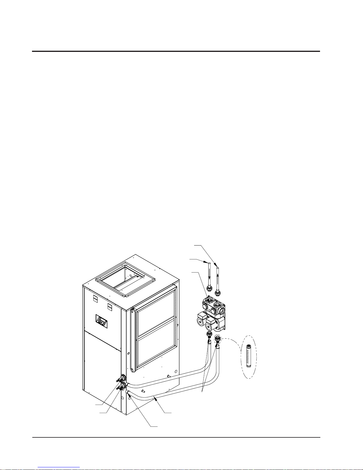
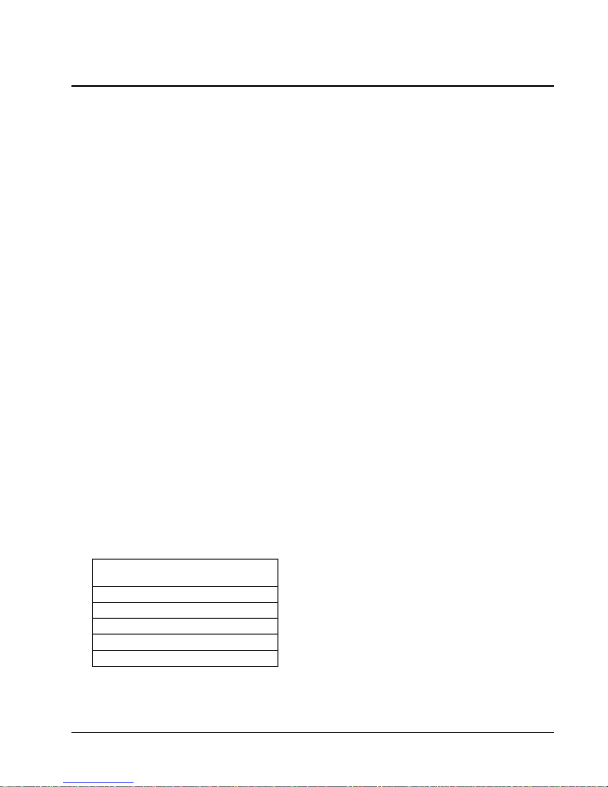
Refer to piping, Figure 10. Slow open/close with End
Switch (2), 24V, provides on/off control of the water flow
to the unit. Refer to the wiring diagram for correct hookup
of the valve solenoid coil.
Constant Flow Valve (3) provides correct flow of water to
the unit regardless of variations in water pressure. Observe
the water flow direction indicated by the arrow on the side
of the valve body. Following is a table showing which
valve is the be installed with which heat pump.
Strainer (8) installed upstream of water coil inlet to collect
foreign material which would clog the flow valve orifice.
The figure shows the use of shutoff valves (4) and (5), on
the in and out water lines to permit isolation of the unit
from the plumbing system should future service work
require this. Globe valves should not be used as shutoff
valves because of the excessive pressure drop inherent in
the valve design. Instead use gate or ball valves as
shutoffs, so as to minimize pressure drop.
Hose bib (6) and (7), and tees should be included to permit
acid cleaning the refrigerant-to-water coil should such
cleaning be required. See WATER CORROSION.
Hose bib (1) provides access to the system to check water
flow through the constant flow valve to insure adequate
water flow through the unit. A water meter is used to
check the water flow rate.
WELL PUMP SIZING
Strictly speaking, sizing the well pump is the responsibility
of the well drilling contractor. It is important, however,
that the HVAC contractor be familiar with the factors that
determine what size pump will be required. Rule of thumb
estimates will invariably lead to under or oversized well
pumps. Undersizing the pump will result in inadequate
water to the whole plumbing system, but with especially
bad results to the heat pump – NO HEAT / NO COOL
calls will result. Oversized pumps will short cycle and
could cause premature pump motor or switch failures.
The well pump must be capable of supplying enough water
and at an adequate pressure to meet competing demands of
water fixtures. The well pump must be sized in such a way
that three requirements are met:
TABLE 8
CONSTANT FLOW VALVES
.oNtraP
5-VFG)1(515
6-VFG)1(516
7-VFG)1(517
9-VFG)1(519
01-VFG)1(5101
(1)
The pressure drop through the constant flow valve
will vary depending on the available pressure
ahead of the valve. Unless minimum of 15 psig
is available immediately ahead of the valve, no
water will flow.
1. Adequate flow rate in GPM.
2. Adequate pressure at the fixture.
3. Able to meet the above from the depth of the
elbaliavA.niM
GISPerusserP
etaRwolF
MPG
well-feet of lift.
Manual 2100-510E
Page 19 of 38
Page 20
The pressure requirements put on the pump are directly
affected by the diameter of pipe being used, as well as, by
the water flow rate through the pipe. The worksheet
included in Manual 2100-078 should guarantee that the
well pump has enough capacity. It should also ensure that
FIGURE 10
WATER CONNECTION COMPONENTS
the piping is not undersized, which would create too much
pressure due to friction loss. High pressure losses due to
undersized pipe will reduce efficiency and require larger
pumps and could also create water noise problems.
8
7
See descriptions for these
reference numbers on Page 19.
Manual 2100-510E
Page 20 of 38
MIS-2623
6
5
4
3
2
1
Page 21

SYSTEM START UP PROCEDURE FOR
GROUND WATER APPLICATIONS
1. Be sure main power to the unit is OFF at disconnect.
2. Set thermostat system switch to OFF, fan switch to
AUTO.
3. Move main power disconnect to ON. Except as required
for safety while servicing – DO NOT OPEN THE UNIT
DISCONNECT SWITCH.
4. Check system airflow for obstructions.
A. Move thermostat fan switch to ON. Blower runs.
B. Be sure all registers and grilles are open.
C. Move thermostat fan switch to AUTO. Blower
should stop.
5. Fully open the manual inlet and outlet valves.
6. Check water flow.
A. Connect a water flow meter to the drain cock
between the constant flow valve and the
solenoid valve. Run a hose from the flow meter
to a drain or sink. Open the drain cock.
B. Check the water flow rate through constant
flow valve to be sure it is the same as the unit
is rated for. (Example: 5 GPM for a GV27S1.)
C. When water flow is okay, close drain cock and
remove the water flow meter. The unit is now
ready to start.
7. Start the unit in cooling mode by moving the thermostat
switch to cool. Fan should be set for AUTO.
A. Check to see the solenoid valve opened.
8. Check the system refrigerant pressures against the
cooling refrigerant pressure table in the installation
manual for rated water flow and entering water
temperatures. If the refrigerant pressures do not match,
check for airflow problem that refrigeration system
problem.
9. Switch the unit to the heat mode by moving the
thermostat switch to heat. Fan should be set for AUTO.
A. Check to see the solenoid valve opened again.
10. Check the refrigerant system pressures against the
heating refrigerant pressure table in installation manual.
Once again, if they do not match, check for airflow
problems and then refrigeration system problems.
NOTE: If a charge problem is determined (high or low):
A. Check for possible refrigerant loss.
B. Discharge all remaining refrigerant from unit.
C. Evacuate unit down to 29 inches of vacuum.
D. Recharge the unit with refrigerant by weight.
This is the only way to insure proper charge.
WATER CORROSION
Two concerns will immediately come to light when
considering a water source heat pump, whether for ground
water or for a ground loop application: Will there be
enough water? And, how will the water quality affect the
system?
Water quantity is an important consideration and one
which is easily determined. The well driller must perform
a pump down test on the well according to methods
described by the National Well Water Association. This
test, if performed correctly, will provide information on the
rate of flow and on the capacity of the well. It is important
to consider the overall capacity of the well when thinking
about a water source heat pump because the heat pump
may be required to run for extended periods of time.
The second concern, about water quality, is equally
important. Generally speaking, if the water is not offensive
for drinking purposes, it should pose no problem for the
heat pump. The well driller or local water softening
company can perform tests which will determine the
chemical properties of the well water.
Water quality problems will show up in the heat pump in
one or more of the following ways:
1. Decrease in water flow through the unit.
2. Decreased heat transfer of the water coil (entering to
leaving water temperature difference is less).
There are four main water quality problems associated with
ground water. These are:
1. Biological Growth. This is the growth of microscopic
organisms in the water and will show up as a slimy
deposit throughout the water system. Shock treatment
of the well is usually required and this is best left up to
the well driller. The treatment consists of injecting
chlorine into the well casing and flushing the system
until all growth is removed.
2. Suspended Particles in the Water. Filtering will
usually remove most suspended particles (fine sand,
small gravel) from the water. The problem with
suspended particles in the water is that it will erode
metal parts, pumps, heat transfer coils, etc. So long as
the filter is cleaned and periodically maintained,
suspended particles should pose no serious problem.
Consult with your well driller.
3. Corrosion of Metal. Corrosion of metal parts results
from either highly corrosive water (acid water,
generally not the case with ground water) of galvanic
reaction between dissimilar metals in the presence of
water. By using plastic plumbing or dielectric unions,
galvanic reaction is eliminated. The use of corrosion
resistant materials such as the Cupronickel coil)
through the water system will reduce corrosion
problems significantly.
Manual 2100-510E
Page 21 of 38
Page 22
4. Scale Formation. Of all the water problems, the
formation of scale by ground water is by far the most
common. Usually this scale is due to the formation of
calcium carbonate but magnesium carbonate or calcium
sulfate may also be present. Carbon dioxide gas (CO2),
the carbonate of calcium and magnesium carbonate, is
very soluble in water. It will remain dissolved in the
water until some outside factor upsets the balance.
This outside influence may be a large change in water
temperature or pressure. When this happens, enough
carbon dioxide gas combines with dissolved calcium or
magnesium in the water and falls out of solution until a
new balance is reached. The change in temperature
that this heat pump produces is usually not high enough
to cause the dissolved gas to fall out of solution.
Likewise, if pressure drops are kept to a reasonable
level, no precipitation of carbon dioxide should occur.
REMEDIES OF WATER PROBLEMS
Water Treatment. Water treatment can usually be
economically justified for water loop systems. However,
because of the large amounts of water involved with a ground
water system, water treatment is generally too expensive.
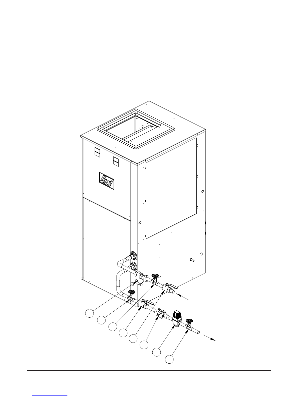
Acid Cleaning the Water Coil or Heat Pump Recovery
Unit. If scaling of the coil is strongly suspected, the coil can
be cleaned up with a solution of Phosphoric Acid (food grade
acid). Follow the manufacturer’s directions for mixing, use,
etc. Refer to the “Cleaning Water Coil”, Figure 11. The acid
solution can be introduced into the heat pump coil through the
hose bib A. Be sure the isolation valves are closed to prevent
contamination of the rest of the system by the coil. The acid
should be pumped from a bucket into the hose bib and
returned to the bucket through the other hose bib B. Follow
the manufacturer’s directions for the product used as to how
long the solution is to be circulated, but it is usually circulated
for a period of several hours.
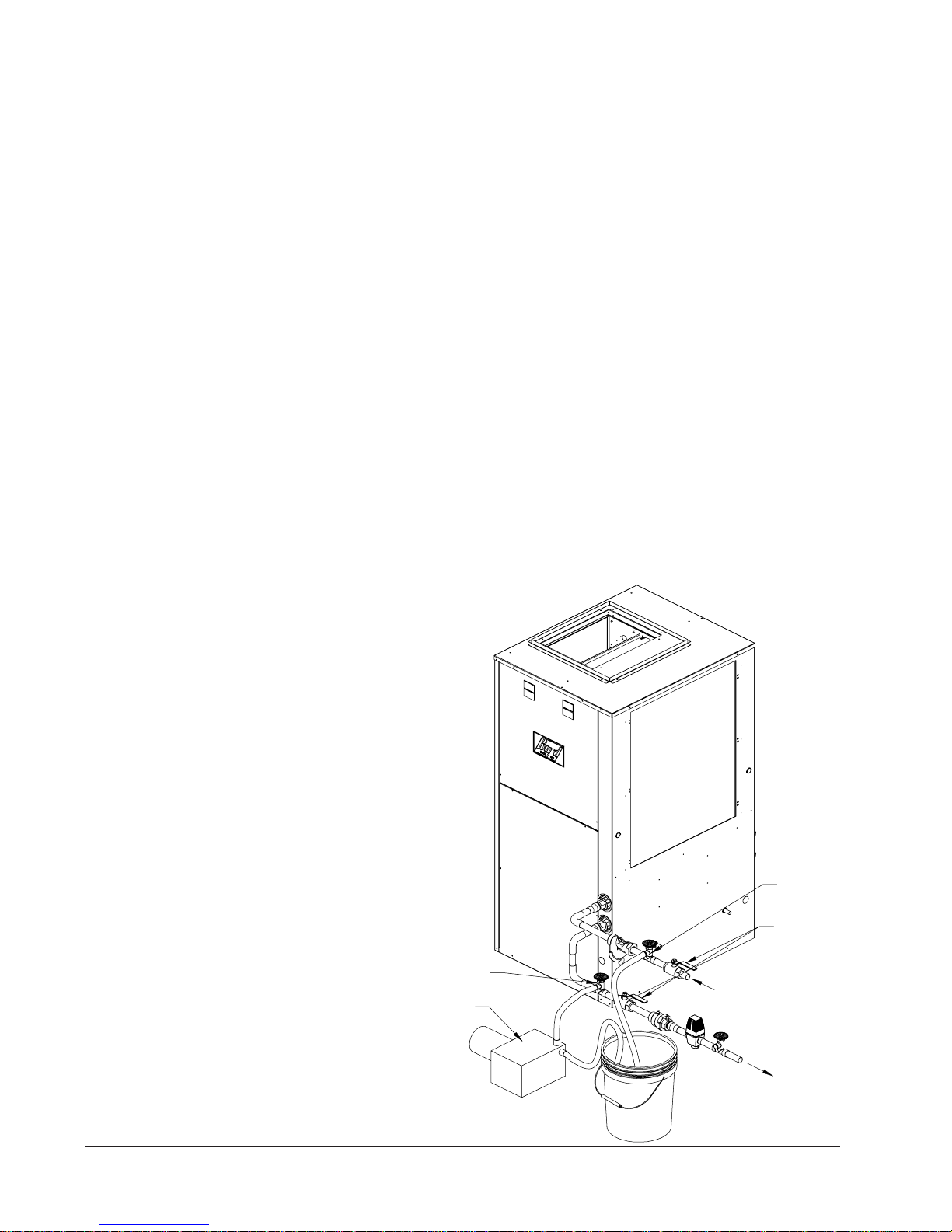
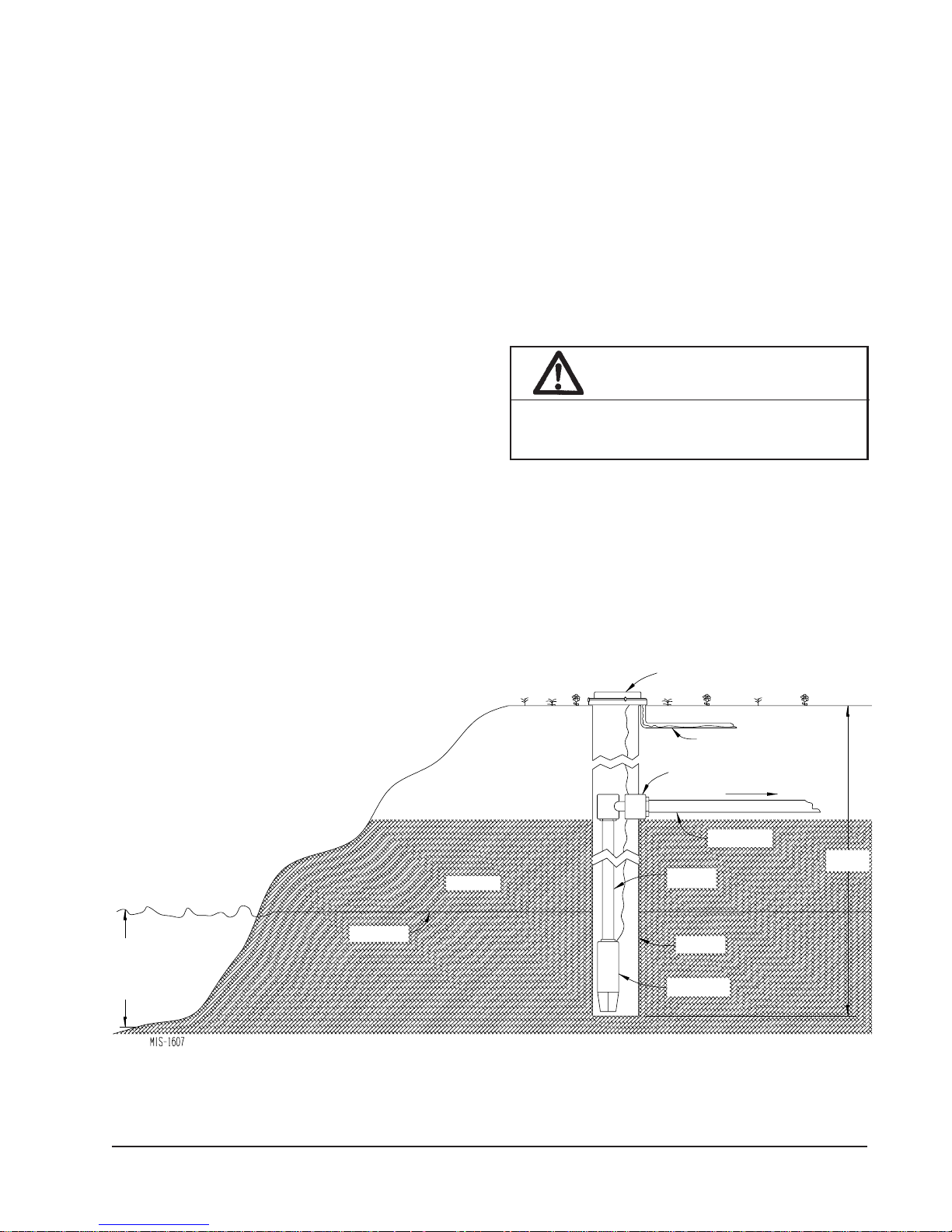
LAKE AND POND INSTALLATIONS
Lakes and ponds can provide a low cost source of water for
heating and cooling with a ground water heat pump. Direct
usage of the water without some filtration is not
recommended as algae and turbid water can foul the water to
refrigerant heat exchanger. Instead, there have been very
good results using a dry well dug next to the water line or
edge. Normal procedure in installing a dry well is to
backhoe a 15 to 20 foot hole adjacent to the body of water
(set backhoe as close to the water’s edge as possible). Once
excavated, a perforated plastic casing should be installed
with gravel backfill placed around the casing. The gravel
bed should provide adequate filtration of the water to allow
good performance of the ground water heat pump.
The following is a list of recommendations to follow when
installing this type of system:
A. A lake or pond should be at least 1 acre (40,000 a
square feet) in surface area for each 50,000 BTUs of
ground water heat pump capacity or have 2 times the
cubic feet size of the dwelling that you are trying to
heat (includes basement if heated).
B. The average water depth should be at least 4 feet and
there should be an area where the water depth is at least
12 to 15 feet deep.
FIGURE 11
CLEANING WATER COIL
Manual 2100-510E
Page 22 of 38
Hose Bib (A)
Pump
Hose Bib (B)
Isolation Valve
MIS-2624
Page 23
C. If possible, use a submersible pump suspended in the
dry well casing. Jet pumps and other types of suction
pumps normally consume more electrical energy than
similarly sized submersible pumps. Pipe the unit the
same as a water well system.
D. Size the pump to provide necessary GPM for the
ground water heat pump. A 12 GPM or greater water
flow rate is required on all models when used on this
type system.
E. A pressure tank should be installed in dwelling to be
heated adjacent to the ground water heat pump. A
pressure switch should be installed at the tank for pump
control.
F. All plumbing should be carefully sized to compensate
for friction losses, etc., particularly if the pond or lake
is over 200 feet from the dwelling to be heated or
cooled.
G. Keep all water lines below low water level and below
the frost line.
H. Most installers use 4-inch field tile (rigid plastic or
corrugated) for water return to the lake or pond.
I. The drain line discharge should be located at least 100
feet from the dry well location.
J. The drain line should be installed with a slope of 2
inches per 10 feet of run to provide complete drainage
of the line when the ground water heat pump is not
operating. This gradient should also help prevent
freezing of the discharge where the pipe terminates
above the frost line.
K. Locate the discharge high enough above high water
level so the water will not back up and freeze inside the
drain pipe.
L. Where the local conditions prevent the use of a gravity
drainage system to a lake or pond, you can instead run
standard plastic piping out into the pond below the
frost and low water level.
WARNING
Thin ice may result in the vicinity of the
discharge line.
For complete information on water well systems and lake
and pond applications, refer to Manual 2100-078 available
from your distributor.
12'
to
15'
LAKE
or
POND
FIGURE 12
LAKE OR POND INSTALLATION
GRAVEL FILL
WATER LEVEL
WELL CAP
ELECTRICAL LINE
PITLESS ADAPTER
TO PRESSURE
TANK
WATER
SUPPLY LINE
DROP
PIPE
PERFORATED
PLASTIC CASING
SUBMERSIBLE
PUMP
15' to 20'
DEEP
Manual 2100-510E
Page 23 of 38
Page 24

SEQUENCE OF OPERATION
BLOWER
Blower functions are all automatic through the thermostat
control. (See Table 1 for the specific airflows on each
speed.) Motor control inputs are all 24 VAC with line
power to motor being continuous.
On a call for “G” from the thermostat (call for manual fan),
speed tap #1 on the blower motor is energized.
On a call for “Y1” from the thermostat (heating or
cooling), speed tap #2 of the blower motor is energized
immediately. Simultaneously, the “Y1” tap of the blower
control board is also energized, and following 5 minutes,
the blower control will power speed tap #3 of the blower
motor.
On a call for “Y2” operation from the thermostat (heating
or cooling), speed tap #5 will be energized through the
blower control board.
connection on the blower control board. It comes from the
factory by default jumpering Pins #4 and #5 together to
run the blower at nominal rated full load airflow. If this is
too noisey, this jumper can be removed from Pins #4/#5 to
allow the full load airflow to be reduced by 10% (see Unit
Wiring Diagram).
On any call for “W” (electric heat operation), from the
thermostat, speed tap #5 is always energized. (It is not
affected by the #4/#5 jumper on the blower control board.)
The exception is a jumper pin
PART LOAD COOLING
When thermostat system switch is placed in COOL, it
completes a circuit from “R” to “O”, energizing the
reversing valve solenoid. On a call for cooling, the
thermostat completes a circuit from “R” to “Y1”, which
energizes the compressor contactor and blower motor on
speed tap #2 initially, then speed tap #3 after 5 minutes
(see BLOWER above).
PART LOAD HEATING (No Electric Heat)
When thermostat system switch is placed in HEAT, the
reversing valve solenoid is no longer energized. On a call
for part load heating, the thermostat completes a circuit
from “R” to “Y1”, which energizes the compressor
contactor and blower motor on speed tap #2 initially, then
speed tap #3 after 5 minutes (see BLOWER above).
FULL LOAD HEATING (No Electric Heat)
The system should already be in Part Load Heating
operation prior to Full Load Heating being energized.
Additionally what happens, the thermostat completes a
circuit from “R” to “Y2”. This sends a signal to both the
staging solenoid on the side of the compressor and
energizes either tap #5 or tap #4 of the blower motor (see
BLOWER above).
SUPPLEMENTARY ELECTRIC HEAT
The system should already be in FULL LOAD HEATING
operation (above). The thermostat completes a circuit from
“R” to “W2”, which energizes up to 9 KW of electric heat
(depends on heater package installed). 9 KW of electric
heat is the limit when operating with the heat pump and is
controlled through the emergency heat relay.
EMERGENCY HEAT MODE
When thermostat system switch is placed in EMERGENCY
HEAT MODE and the thermostat calls for heat, it
completes a circuit from “R” to “E” and from “R” to “W2”.
This will energize the heater package for all available KW
per the installed heater package. (The call from “R” to
“E” locks out compressor operation.) The blower motor is
automatically energized with this function and will run on
speed #5 (see BLOWER above).
FULL LOAD COOLING
The system should already be in Part Load Cooling
operation prior to Full Load Cooling being energized.
Additionally what happens, the thermostat completes a
circuit from “R” to “Y2”. This sends a signal to both the
staging solenoid on the side of the compressor and
energizes either tap #5 (or tap #4) of the blower motor (see
BLOWER above).
Manual 2100-510E
Page 24 of 38
Page 25

SEQUENCE OF OPERATION
COMPRESSOR CONTROL MODULE
The compressor control module is an anti-short cycle/
lockout timer with high and low pressure switch
monitoring and alarm output.
ADJUSTABLE DELAY ON MAKE AND BREAK
TIMER
On a call for compressor operation the delay on make
period begins, which will be 10% of the delay on break
setting. When the delay on make is complete and the high
pressure switch and low pressure switch are closed, the
compressor contactor is energized. Upon shutdown, the
delay on break timer starts and prevents restart until the
delay on break and delay on make periods have expired.
HIGH PRESSURE SWITCH AND LOCKOUT
SEQUENCE (Standard Feature)
If the high pressure switch opens, the compressor contactor
will de-energize immediately. The lockout timer will go
into a soft lockout and stay in soft lockout until the high
pressure switch closes and the delay on make time has
expired. If the high pressure switch opens again in the
same operating cycle, the unit will go into manual lockout
condition and the alarm relay circuit will energize.
Recycling the wall thermostat resets the manual lockout.
PRESSURE SERVICE PORTS
High and low pressure service ports are installed on all
units so that the system operating pressures can be
observed. Pressure tables can be found later in the manual
covering all models. It is imperative to match the correct
pressure table to the unit by model number.
SYSTEM START-UP
Step 1 – Close disconnect switch(es) and set the
thermostat to cool and the temperature to the
highest setting.
Step 2 – Check for proper airflow across the indoor coil.
Step 3 – Connect the service gauges and allow the unit to
run for at least 10 minutes or until pressures are
stable. Check pressures to the system pressure
table attached to the unit service panel.
Step 4 – Fill out Ground Source Heat Pump Performance
Report.
LOW PRESSURE SWITCH, BYPASS AND
LOCKOUT SEQUENCE (Standard Feature)
If the low pressure switch opens for more than 120
seconds, the compressor contactor will de-energize and go
into a soft lockout. Regardless the state of the low pressure
switch, the contactor will reenergize after the delay on
make time delay has expired. If the low pressure switch
remains open, or opens again for longer than 120 seconds
in the same operating cycle, the unit will go into manual
lockout condition and the alarm relay circuit will energize.
Recycling the wall thermostat resets the manual lockout.
ALARM OUTPUT
Alarm terminal is output connection for applications where
alarm signal is desired. This terminal is powered whenever
compressor is locked out due to HPC or LPC sequences as
described.
Note: Both high and low pressure switch controls are
inherently automatic reset devices. The high pressure
switch and low pressure switch cut out and cut in settings
are fixed by specific air conditioner or heat pump unit
model. The lockout feature, both soft and manual, are a
function of the Compressor Control Module.
Manual 2100-510E
Page 25 of 38
Page 26

FIGURE 13
COMPONENT LOCATION
LOW PRESSURE SWITCHES
SUCTION SERVICE PORT
DISCHARGE SERVICE PORT
DESUPERHEAT COIL
HIGH VOLTAGE IN
FLOW CENTER
POWER
WATER COIL
EXPANSION VALVE
COMPRESSOR
HIGH PRESSURE SWITCH
REVERSING VALVE
TERMINAL
BLOCK
FIGURE 14
CONTROL PANEL
GROUND
BLOCK CONTROL MODULE
COMPRESSOR
CONTACTOR
CIRCUIT
BREAKER
TRANSFORMER
COMPRESSOR
COMPRESSOR
CAPACITOR
RELAY
MIS-2625
E. HEAT
PLUG
BLOWER CONTROL
TERMINAL
STRIP
MIS-2626 A
Manual 2100-510E
Page 26 of 38
Page 27

FIGURE 15
Manual 2100-510E
Page 27 of 38
Page 28

061
124
541
551
761
234
941
931
724
744
454
834
261
571
793
304
051
061
271
641
751
204
724
314
861
304
314
824
471
581
773
773
951
841
441
451
004
341
351
973
241
251
F°lioCretaWgniretnEerutarepmeTdiulF—GNILOOCDAOLLLUF
853
141
151
833
041
051
713
931
941
692
831
841
572
731
741
452
431
441
932
131
041
422
821
731
012
831
661
704
524
014
731
461
983
863
643
523
403
282
162
642
032
512
683
304
183
531
361
563
431
261
543
853
161
231
423
633
131
061
403
413
921
951
382
292
821
851
262
072
521
451
842
452
121
151
332
832
741
812
811
222
234
714
751
641
693
014
551
541
883
573
341
453
241
333
113
041
931
092
731
962
331
452
031
932
621
422
F°lioCretaWgniretnEerutarepmeTdiulF—GNITAEHDAOLLLUF
451
663
251
443
151
223
941
003
741
872
341
362
931
742
631
232
451
761
883
393
851
541
973
383
051
731
373
073
163
241
921
363
121
431
353
253
521
343
343
211
401
333
433
711
123
901
523
89
001
803
613
39
492
803
78
29
182
992
18
38
941
841
741
F°lioCretaWgniretnEerutarepmeTdiulF—GNILOOCDAOLTRAP
641
541
441
341
241
731
331
821
171
951
283
293
173
851
263
143
751
053
123
651
923
103
551
903
451
082
882
351
062
762
251
042
642
741
422
032
241
802
412
391
731
891
541
551
761
383
604
071
483
961
263
143
861
761
913
661
892
461
672
361
552
851
832
122
251
741
502
393
604
441
451
661
363
273
583
153
341
351
461
343
141
223
041
203
931
282
831
262
731
242
231
722
821
312
421
891
463
151
133
361
243
161
123
051
013
941
061
982
992
741
851
962
872
641
751
842
752
142
251
241
332
731
841
622
812
331
341
302
012
671
561
963
963
163
761
751
063
153
851
841
F°lioCretaWgniretnEerutarepmeTdiulF—GNITAEHDAOLTRAP
353
941
041
243
543
131
041
433
733
131
321
523
923
123
221
613
411
701
903
311
413
401
203
603
99
492
992
59
29
192
782
68
48
421
FIGURE 16A
PRESSURE TABLES
591
121
081
561
811
051
511
F°03 F°53 F°04 F°54 F°05 F°55 F°06 F°56 F°07 F°57 F°08 F°58 F°09 F°59 F°001 F°501 F°011
531
111
erusserP
ediShgiH
ediSwoL
erutarepmeT
riAnruteR
BW°26
BD°57
ledoM
231
331
341
002
481
031
931
621
961
531
321
351
231
831
821
911
ediShgiH
ediSwoL
ediSwoL
321
402
511
602
191
981
111
801
571
571
401
061
951
101
541
341
ediShgiH
ediShgiH
ediSwoL
612
902
102
821
491
911
421
581
971
511
021
071
461
211
451
801
941
611
ediShgiH
ediShgiH
ediSwoL
ediSwoL
riAnruteR
BW°76
BD°08
BW°26
BW°27
BD°57
BD°58
1S72VG
BW°27
BW°76
BD°58
BD°08
1S83VG
192
862
57
57
282
552
66
07
142
472
85
46
562
822
85
94
752
F°5 F°01 F°51 F°02 F°52 F°03 F°53 F°04 F°54 F°05 F°55 F°06 F°56 F°07 F°57 F°08 F°58
erusserP
512
14
25
ediShgiH
ediShgiH
ediSwoL
ediSwoL
erutarepmeT
BD°07
BD°07
1S83VG
1S72VG
ledoM
321
811
311
901
F°03 F°53 F°04 F°54 F°05 F°55 F°06 F°56 F°07 F°57 F°08 F°58 F°09 F°59 F°001 F°501 F°011
401
erusserP
ediSwoL
erutarepmeT
riAnruteR
BD°57
ledoM
141
771
231
281
161
621
561
121
641
941
031
331
611
111
411
711
ediShgiH
ediShgiH
ediSwoL
BW°26
BW°76
BD°08
1S72VG
481
881
021
921
981
831
591
171
961
631
451
031
521
831
121
911
ediShgiH
ediSwoL
421
471
331
611
551
211
801
041
401
621
ediShgiH
ediSwoL
081
461
021
951
921
441
421
941
511
921
431
111
911
ediShgiH
ediShgiH
ediSwoL
ediSwoL
riAnruteR
BW°26
BW°27
BD°58
BW°76
BD°57
BW°27
BD°08
BD°58
1S83VG
082
482
77
77
372
672
86
96
562
962
95
26
162
852
05
45
152
F°5 F°01 F°51 F°02 F°52 F°03 F°53 F°04 F°54 F°05 F°55 F°06 F°56 F°07 F°57 F°08 F°58
erusserP
452
14
74
ediShgiH
ediShgiH
ediSwoL
ediSwoL
erutarepmeT
BD°07
BD°07
1S83VG
1S72VG
ledoM
Manual 2100-510E
Page 28 of 38
Page 29

FIGURE 16B
PRESSURE TABLES
ledoM
1S15VG
1S16VG
1S17VG
ledoM
1S15VG
1S16VG
1S17VG
ledoM
1S15VG
1S16VG
1S17VG
ledoM
1S15VG
1S16VG
1S17VG
riAnruteR
erutarepmeT
BD°57
BW°26
BD°08
BW°76
BD°58
BW°27
BD°57
BW°26
BD°08
BW°76
BD°58
BW°27
BD°57
BW°26
BD°08
BW°76
BD°58
BW°27
riAnruteR
erutarepmeT
BD°07
BD°07
BD°07
riAnruteR
erutarepmeT
BD°57
BW°26
BD°08
BW°76
BD°58
BW°27
BD°57
BW°26
BD°08
BW°76
BD°58
BW°27
BD°57
BW°26
BD°08
BW°76
BD°58
BW°27
riAnruteR
erutarepmeT
BD°07
BD°07
BD°07
F°03 F°53 F°04 F°54 F°05 F°55 F°06 F°56 F°07 F°57 F°08 F°58 F°09 F°59 F°001 F°501 F°011
erusserP
ediSwoL
401
601
901
211
511
711
021
321
521
721
821
ediShgiH
141
751
371
981
502
122
632
252
862
ediSwoL
111
411
711
021
321
521
821
ediShgiH
541
161
871
491
012
ediSwoL
911
221
621
ediShgiH
051
ediSwoL
ediShgiH
ediSwoL
ediShgiH
ediSwoL
ediShgiH
ediSwoL
ediShgiH
ediSwoL
ediShgiH
ediSwoL
ediShgiH
erusserP
ediSwoL
ediShgiH
ediSwoL
ediShgiH
ediSwoL
ediShgiH
erusserP
ediSwoL
ediShgiH
ediSwoL
ediShgiH
ediSwoL
ediShgiH
ediSwoL
ediShgiH
ediSwoL
ediShgiH
ediSwoL
ediShgiH
ediSwoL
ediShgiH
ediSwoL
ediShgiH
ediSwoL
ediShgiH
erusserP
ediSwoL
ediShgiH
ediSwoL
ediShgiH
ediSwoL
ediShgiH
761
801
011
341
061
611
811
741
461
521
721
251
961
011
111
571
681
811
911
971
191
721
821
581
791
F°5 F°01 F°51 F°02 F°52 F°03 F°53 F°04 F°54 F°05 F°55 F°06 F°56 F°07 F°57 F°08 F°58
43
24
372
282
73
54
272
382
83
54
952
862
F°03 F°53 F°04 F°54 F°05 F°55 F°06 F°56 F°07 F°57 F°08 F°58 F°09 F°59 F°001 F°501 F°011
601
901
721
241
311
711
031
641
121
521
531
151
801
111
631
051
511
811
931
451
421
721
441
951
801
111
931
351
611
811
341
751
521
721
841
361
F°5 F°01 F°51 F°02 F°52 F°03 F°53 F°04 F°54 F°05 F°55 F°06 F°56 F°07 F°57 F°08 F°58
14
94
652
462
14
94
152
162
93
74
942
852
921
481
102
211
411
671
291
021
221
081
791
921
131
781
402
211
311
791
902
021
121
202
412
921
031
902
122
05
85
192
003
35
16
492
503
25
95
872
782
211
511
751
271
021
421
161
771
921
331
761
381
411
711
561
971
221
521
961
481
131
431
571
091
311
511
761
181
121
321
271
681
031
231
871
291
75
56
372
182
85
66
172
182
55
46
762
772
622
231
531
712
432
611
811
802
422
421
621
412
032
331
531
122
832
511
611
022
132
321
421
622
732
231
331
332
542
56
37
803
713
96
77
513
623
66
37
792
603
911
221
781
202
721
131
291
802
731
041
991
512
021
321
491
902
821
131
991
412
831
141
602
122
711
911
591
902
521
721
002
412
431
731
702
222
37
18
092
892
57
38
192
103
27
08
682
592
131
342
952
831
141
152
862
021
221
142
752
821
031
742
362
831
041
552
372
711
811
342
452
521
621
942
062
431
531
752
962
18
98
623
533
58
39
733
843
08
78
613
523
521
921
712
332
431
831
322
932
441
841
132
742
621
921
322
832
531
831
922
442
541
841
732
352
121
321
322
732
031
231
922
342
931
241
632
152
98
79
703
513
29
001
113
123
88
79
403
413
982
431
531
572
692
441
541
582
703
321
521
372
392
231
331
082
103
241
341
092
113
911
911
562
682
721
721
272
392
731
731
282
403
69
401
343
253
101
901
853
963
49
101
533
443
231
331
842
862
141
341
452
572
251
351
362
482
231
331
352
372
141
241
952
082
251
351
862
982
521
721
152
172
431
531
752
872
441
541
662
882
501
311
423
233
901
711
133
143
501
311
323
233
921
903
033
731
831
713
933
741
841
823
053
621
721
413
433
531
631
223
343
541
641
333
453
911
021
703
823
821
821
513
633
731
831
623
843
311
321
363
473
811
721
283
593
111
121
553
663
531
631
882
803
441
641
592
613
551
651
603
723
431
531
392
213
341
541
003
123
451
551
113
233
821
921
192
213
731
831
992
023
741
841
903
133
321
231
243
153
621
531
153
263
321
231
143
153
F°lioCretaWgniretnEerutarepmeTdiulF—GNILOOCDAOLLLUF
031
231
331
153
173
931
141
063
183
051
151
273
493
821
031
453
573
731
931
363
483
841
941
673
893
021
021
843
963
821
921
753
973
831
831
073
293
431
293
314
241
341
204
324
351
451
614
834
131
231
593
514
041
141
504
624
151
251
914
144
121
121
093
114
921
921
004
124
931
931
414
634
F°lioCretaWgniretnEerutarepmeTdiulF—GNITAEHDAOLLLUF
231
141
051
583
693
631
541
804
124
131
141
673
783
061
704
814
451
361
434
744
151
161
893
904
F°lioCretaWgniretnEerutarepmeTdiulF—GNILOOCDAOLTRAP
731
931
041
823
843
741
941
733
753
851
061
843
073
631
731
233
253
641
741
143
263
751
851
353
473
031
231
233
253
931
141
043
163
051
151
253
473
241
963
983
051
251
873
993
161
361
193
314
831
931
273
293
841
941
283
304
951
061
593
714
331
431
273
393
241
341
283
304
351
451
593
714
F°lioCretaWgniretnEerutarepmeTdiulF—GNITAEHDAOLTRAP
241
151
161
163
073
441
351
273
283
241
151
063
963
071
083
983
261
171
293
304
161
071
873
883
LOW SIDE PRESSURE +/- 2 PSIG
HIGH SIDE PRESSURE +/- 5 PSIG
Tables based upon rated CFM (airflow) across the evaporator coil.
If incorrect charge suspected (more than +2 psig suction, +5 psig liquid), it is recommended refrigerant charge be reclaimed, system evacuated and charged
to serial plate quantity.
531
334
541
444
651
064
331
634
341
744
351
264
121
234
031
344
931
854
961
924
271
064
171
914
341
904
351
914
461
434
141
214
051
324
261
834
531
314
541
424
651
834
081
993
081
314
081
793
Manual 2100-510E
Page 29 of 38
Page 30

AUX.
I
d
Bl
M
W
Heat Gen.
otor
ower
and Coil
oor
INDOOR SECTIONPOWER SUPPLY
n
ev.
Valve Water Coil
ater
Solenoid
WATER COIL SECTION
Line Voltage Control Circuit Compressor Refrigerant System
QUICK REFERENCE TROUBLESHOOTING CHART FOR WATER TO AIR HEAT PUMP
Auxillary Heat Upstream of Coil
Undersized or Restricted Ductwork
Air Filters Dirty
Air Volume Low
Motor Winding Defective
Fins Dirty or Plugged
Plugged or Restricted Metering Device (Clg)
Low Water Temperature (Htg)
Water Volume Low (Clg)
Water Volume Low (Htg)
Scaled or Plugged Coil (CLg)
Scaled or Plugged Coil (Htg)
Plugged or Restricted Metering Device (Htg)
Defective Valve or Coil
Leaking
Solenoid Valve Stuck Open (Htg or Clg)
Solenoid Valve Stuck Closed (Clg)
Solenoid Valve Stuck Closed (Htg)
Unequalized Pressures
Non-Condensables
Low Suction Pressure
High Suction Pressure
Low Head Pressure
High Head Pressure
Refrigerant Overcharge
Refrigerant Charge Low
Motor Wingings Defective
Valve Defective
Seized
Bearings Defective
Discharge Line Hitting Inside of Shell
Indoor Blower Relay
Pressure Controls (High or Low)
Contactor Coil
Thermostat
Low Voltage
Control Transformer
Loose Terminals
Faulty Wiring
Start Capacitor
Run Capacitor
Potential Relay
Compressor Overload
Defective Contacts in Contactor
Low Voltage
Loose Terminals
Faulty Wiring
Blown Fuse or Tripped Breaker
Power Failure
Denotes occasional cause
Denotes common cause
Manual 2100-510E
Page 30 of 38
Compressor Will Not Run
No Power at Contactor
Compressor Will Not Run
Power at Contactor
Compressor "Hums"
But Will Not Start
Compressor Cycles on Overload
Thermostat Check Light
Lite-Lockout RelayCompressor Off on High
Pressure Control
Compressor Off on Low
Pressure Control
Compressor Noisy
Head Pressure Too High
Head Pressure Too Low
Suction Pressure Too High
Suction Pressure Too Low
I.D. Blower Will Not Start
I.D. Coil Frosting or Icing
High Compressor Amps
Excessive Water Usage
Compressor Runs Continuously
– No Cooling
Liquid Refrigerant Flooding Back
To Compressor
Compressor Runs Continuously
– No Heating
Reversing Valve Does Not Shift
Liquid Refrigerant Flooding Back
To Compressor
Cycle
Heating or Cooling Cycles
Cooling
Aux. Heat on I.D. Blower Off
Excessive Operation Costs
Ice in Water Coil
Heating Cycle
Page 31

SERVICE
SERVICE HINTS
1. Caution owner to maintain clean air filters at all times.
Also, not to needlessly close off supply and return air
registers. This reduces airflow through the system,
which shortens equipment service life as well as
increasing operating costs.
2. Check all power fuses or circuit breakers to be sure that
they are the correct rating.
UNBRAZING SYSTEM COMPONENTS
If the refrigerant charge is removed from a scroll equipped
unit by bleeding the high side only, it is sometimes possible
for the scrolls to seal, preventing pressure equalization
through the compressor. This may leave low side shell and
suction line tubing pressurized. If the brazing torch is then
applied to the low side while the low side shell and suction
line contains pressure, the pressurized refrigerant and oil
mixture could ignite when it escapes and contacts the
brazing flame. To prevent this occurrence, it is important
to check both the high and low side with manifold gauges
before unbrazing.
This unit is equipped with an ECM motor. It is important
that the blower motor plugs are not plugged in or
unplugged while the power is on. Failure to remove power
prior to unplugging or plugging in the motor could result in
motor failure.
COMPRESSOR SOLENOID
(See Sequence of Operation on Pages 24 & 25 for function.)
A nominal 24-volt direct current coil activates the internal
compressor solenoid. The input control circuit voltage must
be 18 to 28 volt ac. The coil power requirement is 20 VA.
The external electrical connection is made with a molded
plug assembly. This plug contains a full wave rectifier to
supply direct current to the unloader coil.
Compressor Solenoid Test Procedure
suspected that the unloader is not working, the following
methods may be used to verify operation.
1. Operate the system and measure compressor amperage.
Cycle the compressor solenoid on and off at 10-second
intervals. The compressor amperage should go up or
down at least 25 percent.
2. If step one does not give the expected results, shut unit
off. Apply 18 to 28 volt ac to the solenoid molded
plug leads and listen for a click as the solenoid pulls in.
Remove power and listen for another click as the
solenoid returns to its original position.
3. If clicks can’t be heard, shut off power and remove the
control circuit molded plug from the compressor and
measure the solenoid coil resistance. The resistance
should be 32 to 60 ohms depending on compressor
temperature.
4. Next, check the molded plug.
– If it is
WARNING
Both the high and low side of the scroll
compressor must be checked with manifold
gauges before unbrazing system
components. Failure to do so could cause
pressurized refrigerant and oil mixture to
ignite if it escapes and contacts the brazing
flame causing property damage, bodily harm
or death.
CAUTION
Do not plug in or unplug blower motor
connectors while the power is on. Failure
to do so may result in motor failure.
Voltage check:
(18 to 28 volt ac). The measured
connectors in the plug should be around 15 to 27 vdc.
Resistance check:
one molded plug lead to either of the two female
connectors in the plug. One of the connectors should read
close to zero ohms, while the other should read infinity.
Repeat with other wire. The same female connector as
before should read zero, while the other connector again
reads infinity. Reverse polarity on the ohmmeter leads and
repeat. The female connector that read infinity previously
should now read close to zero ohms.
Replace plug if either of these test methods does not show
the desired results.
Apply control voltage to the plug wires
dc voltage at the female
Measure the resistance from the end of
Manual 2100-510E
Page 31 of 38
Page 32
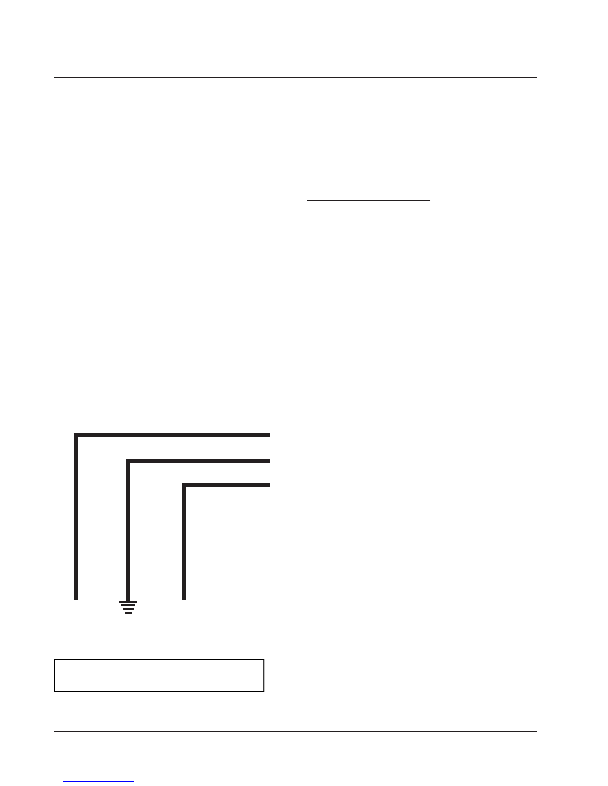
TROUBLESHOOTING GE X13-SERIES ECM MOTORS
If the Motor is Running
1. It is normal for the motor to rock back and forth on start
up. Do not replace the motor if this is the only problem
identified.
2. If the system is excessively noisy, does not appear to
change speeds in response to a demand (Heat, Cool, Other), or
is having symptoms during the cycle such as tripping limit or
freezing coil, check the following:
a. Wait for programmed delays to time out.
b. Ensure that the motors control inputs are wired to the
factory supplied wiring diagram to insure motor is
getting proper control signals and sequencing.
c. Remove the filter and check that all dampers, registers,
and grilles are open and free flowing. If removing the
filters corrects the problem, clean or replace with a less
restrictive filter. Also check and clean the blower
wheel or coil as necessary.
d. Check the external static pressure (total of both supply
and return) to insure that you are within the ranges as
listed on the unit serial plate. If higher than allowed,
additional duct work is needed.
e. If the motor does not shut off at the end of the cycle,
wait for any programmed delays to time out (no more
than 90 seconds). Also make sure that there is no call
for “Continuous Fan” on the "G" terminal.
f. If the above diagnostics do not solve the problem,
confirm the voltage checks in the next section below,
then continue with the “Model X13 Communication
Diagnostics”.
If the Motor is Not Running
1. Check for proper high voltage and ground at the (L/L1)
(G) (N/L2) connections at the motor (see Figure 17). Correct
any voltage issues before proceeding to the next step. The
X13 Motor is voltage specific. Only the correct voltage
should be applied to the proper motor. Input voltage within
plus or minus 10% of the nominal 230 VAC is acceptable.
2. If the motor has proper high voltage and ground at the
(L/L1) (G) (N/L2) connections, then continue with the “Model
X13 Communication Diagnostics”.
↓
L2 LINE
POWER
EARTH
GROUND
↓
L1 LINE
POWER
NOTE: MOTOR IS CONSTANTLY
POWERED BY LINE VOLTAGE
FIGURE 17
Manual 2100-510E
Page 32 of 38
Page 33
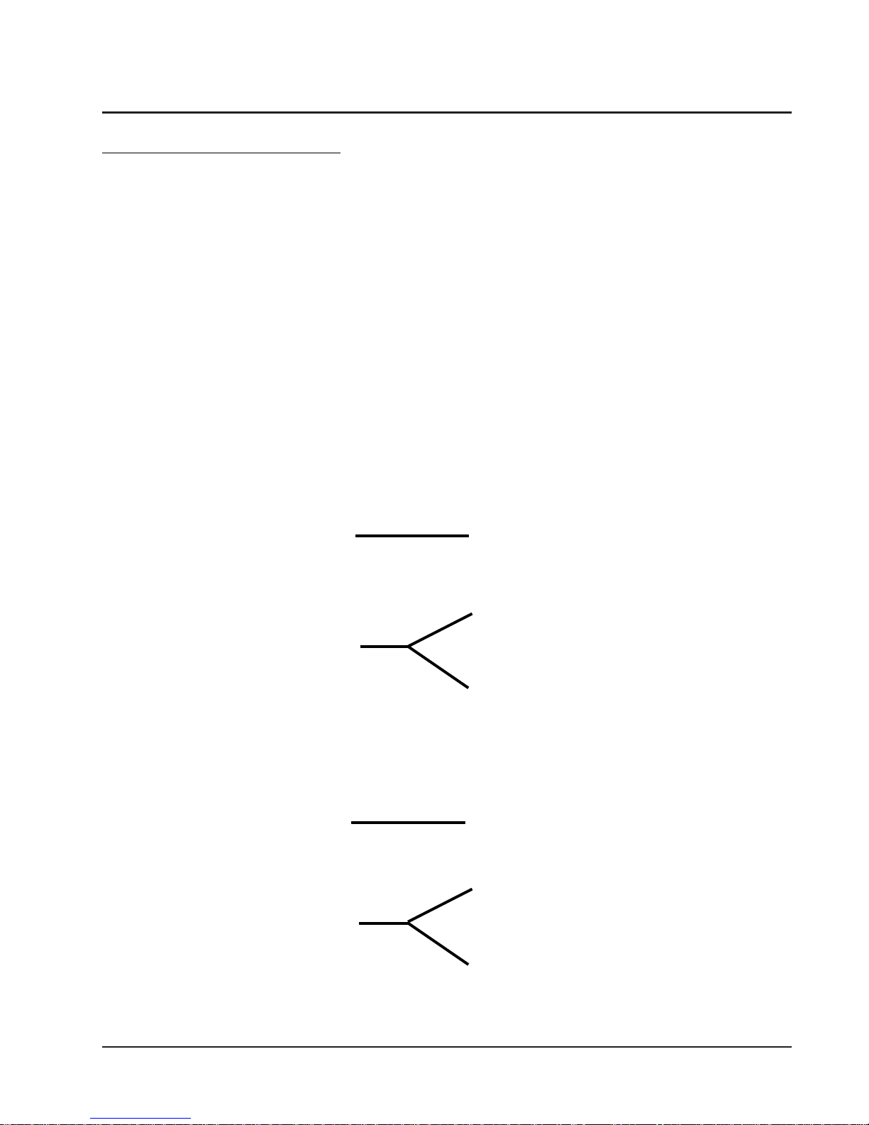
TROUBLESHOOTING GE X13-SERIES ECM MOTORS
CONT’D.
Model X13 Communication Diagnostics
The X13 motor is communicated through 24 VAC low voltage
(Thermostat Control Circuit Wiring).
1. Start with unit wiring diagram to confirm proper
connections and voltage (see Figure 18).
FIGURE 18
24VAC Common
2. Initiate a demand from the thermostat and check the
voltage between the common and the appropriate motor
terminal (1-5). ("G" input is typically on terminal #1, but
refer to wiring diagram!)
a
. If the low voltage communication is not present, check
the demand from the thermostat. Also check the
output terminal and wire(s) from the terminal strip or
control relay(s) to the motor.
b. If the motor has proper high voltage as identified
above (Motor not Running #1), and proper low voltage
to a programmed terminal, and is not operating, the
motor is failed, and will require replacement.
24VAC "R" Signal through
thermostat output.
24VAC Common
24VAC "R" Signal through
thermostat output.
Manual 2100-510E
Page 33 of 38
Page 34
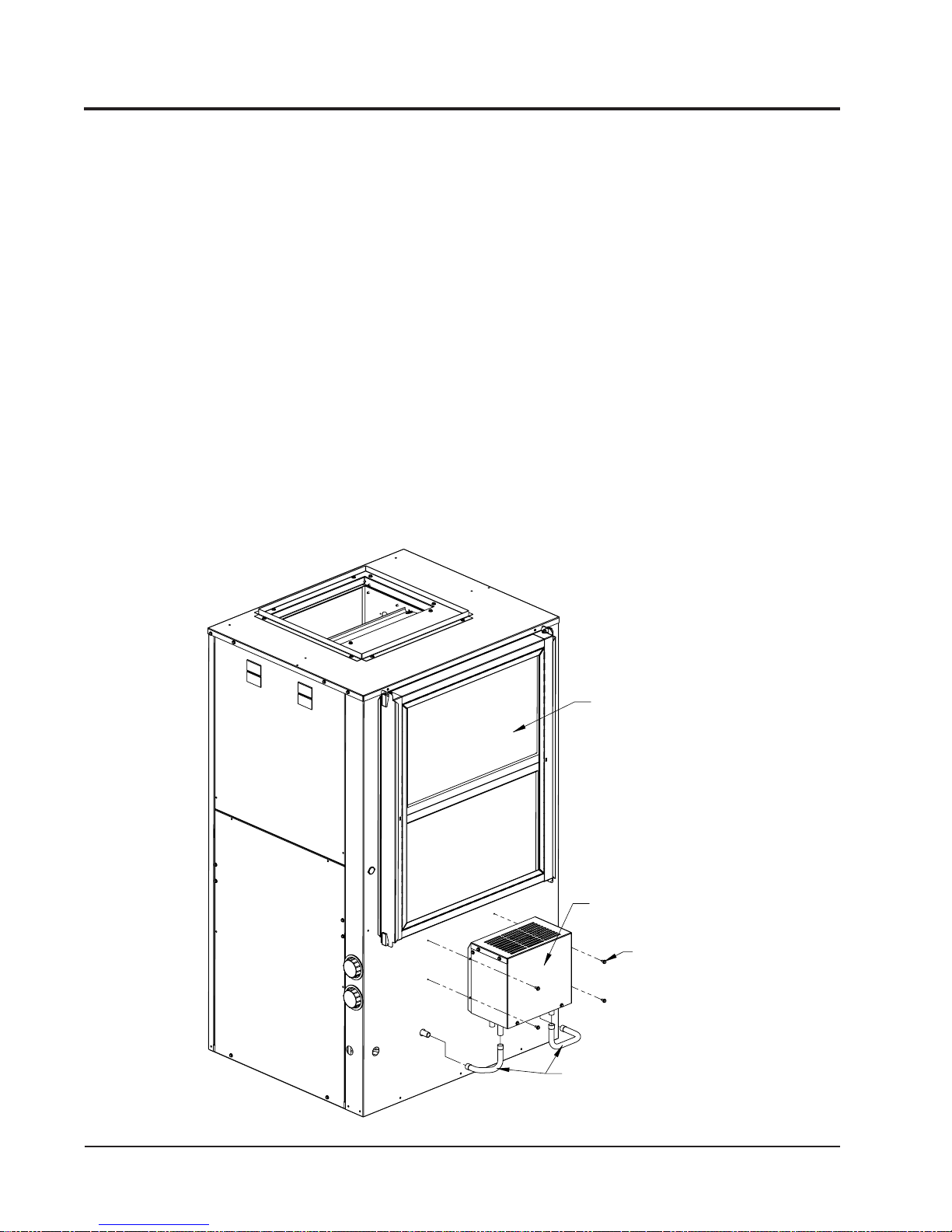
ACCESSORIES
ADD-ON GVDM-26 PUMP MODULE KIT
NOTE: This section applies only if a GVDM-26 Pump
Module is added. Refer to GVDM-26 instructions for
complete installation details.
GENERAL
This high efficiency water source heat pump series was
designed with a refrigerant to water heat exchanger
commonly know as a desuperheater coil factory-installed
for ease in installing optional GVDM-26 pump module kit.
The addition of this optional kit allows for heat recovery
for hot water heating when connected to a home water
heater. The amount of annual hot water supplied and thus
additional energy cost savings will depend on the amount
of hot water usage and the number of hours the heat pump
operates. This pump kit is suitable for potable water.
FIGURE 19
TYPICAL PUMP KIT CONNECTION TO UNIT
INSTALLATION
1. Follow all local, state, and national codes applicable to
the installation of the pump module kit.
2. Follow the installation instructions received with the
GVDM-26 pump module kit.
3. Connect the water lines between the unit, pump module
kit, and the water heater.
4. Pump power is 115V-60Hz 1-phase. A 6-foot, 3-prong
cord is supplied. Pump control is accomplished by 18
gauge 3-wire connection (field-supplied) from Pump
Module to the GV Heat Pump 24V terminal strip.
NOTE: The GVDM-26 Pump Module can be installed on
adjacent surface or nearer to hot water storage
tank if that easier facilitates the plumbing or
electrical connection.
FILTER ASSEMBLY
DESUPERHEATER
PUMP MODULE
ATTACH TO UNIT
USING PROVIDED
SCREWS
INLET AND OUTLET TUBES
SUPPLIED WITH PUMP MODULE
MIS-2647
Manual 2100-510E
Page 34 of 38
Page 35

GROUND SOURCE HEAT PUMP
PERFORMANCE REPORT
This performance check report should be filled out by installer and retained with unit.
DATE
1. UNIT:
Mfgr Model No. S/N
THERMOSTAT:
Mfgr Model No. P/N
2. Person Reporting
3. Company Reporting
4. Installed By Date Installed
5. User’s (Owner’s) Name
Address
6. Unit Location
WATER SYSTEM INFORMATION
TAKEN BY:
7. Open Loop System (Water Well) Closed Loop System
A. If Open Loop where is water discharged?
8. The following questions are for
A. Closed loop system designed by
B. Type of antifreeze used % Solution
C. System type: Series Parallel
D. Pipe material Nominal Size
E. Pipe Installed:
1. Horizontal Total length of pipe ft
No. pipes in trench Depth bottom pipe ft
2. Vertical Total length of bore hole ft
Closed Loop systems only
Manual 2100-510E
Page 35 of 38
Page 36

THE FOLLOWING INFORMATION IS NEEDED
TO CHECK PERFORMANCE OF UNIT.
FLUID SIDE DATA Cooling ** Heating
9. Entering fluid temperature F
10. Leaving fluid temperature F
11. Entering fluid pressure PSIG
12. Leaving fluid pressure PSIG
13. Pressure drop through coil PSIG
14. Gallons per minute through the water coil GPM
15. Liquid or discharge line pressure PSIG
16. Suction line pressure PSIG
17. Voltage at compressor (unit running) V
18. Amperage draw at line side of contactor A
19. Amperage at compressor common terminal A
20. * Suction line temperature 6” from compressor F
21. * Superheat at compressor F
22. * Liquid line temperature at metering device F
23. * Coil subcooling F
INDOOR SIDE DATA Cooling ** Heating
24. Dry bulb temperature at air entering indoor coil F
25. Wet bulb temperature of air entering indoor coil F
26. Dry bulb temperature of air leaving indoor coil F
27. Wet bulb temperature of air leaving indoor coil F
28. * Supply air static pressure (packaged unit) WC
29. * Return air static pressure (packaged unit) WC
30. Other information about installation
** When performing a heating test insure that 2nd stage heat is not activated
* Items that are optional
Manual 2100-510E
Page 36 of 38
Page 37
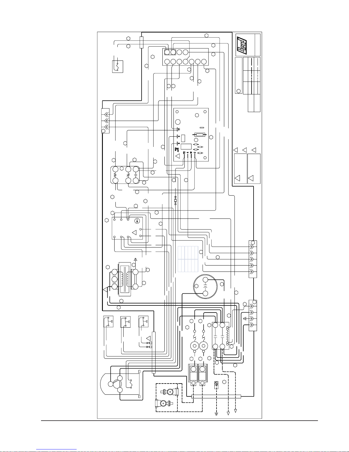
26
3 pin plug for Heater Package
1
2
3
12
High Pressure Switch
Red
2
Red
Compressor
Reversing Valve
9
Compre ssor
7
Transformer
Red
Control Module
Black
R
Blue/White
Blue/White
28
Red/Yellow
Yellow
31
11
31
Heat Relay
Emergency
26
Black/White
35
CC
ALR
HPC
R
240V 208V COM
36
36
Low Pressure
Switch (Water)
Blue
Blue
C
S
29 29
5
6
C
Y
28
24
Black/White
14
5
4
3
2
MINUTES
1
26
C
R
Low Pressure
Switch (Anti-freeze)
High Speed
Bryan, Ohio
4105-104
For antifreeze applications change low
1
Wire Identification numbers
for Bard use only.
99
pressure swit ch to yellow leads on
compressor control module "LPC" terminals
WARNING
!
USE COPPER CONDUCTORS
ONLY SUITABLE FOR AT LEAST
Bard Mfg. Co.
OptionalFactory
Field
Low Voltage
High Volt age
operation move t his jumper
For -10% airflow in stage #2
wire to 208V transformer tap
For 208V operati on move this
off of 4-5
3
2
75° C.
DANGER
!
*ELECTRICAL SHOCK HAZARD
*DISCONNECT POWER BEFORE
SERVICING.
R
A
C
15
Low Voltage
12
Black/White
Brown
Blue/Black
C
G
Term. Strip
O
Y1
W
Y2
12
12
28
28
Yellow
Orange
Blue/Black
30
Purple
3
12
Blue/Black
12
30
12
28
Purple
25 27
L
E
14
31
Red/Yellow
Pink
Black/White
Red/White
17
Black/White
Blower Cont rol
26
34
Red/White
Yellow/Brown
Blue
14
1
LPC
Red/White
25
Yellow
Yellow
25
Blue
Blue
Red
Red
Black/White
26
1
Model Capacitor
GV27S 35/370
GV38S 40/370
GV51S 45/370
Blue
Blue
Red
Red
Blue
Blue
38
Red
4
Black
Yellow
Circuit Breakers
38
Solenoid
GV61S 80/370
GV71S 80/370
19
Red
3
PUSH3PUSH
Red
L1
Yellow/Red
Orange
Yellow
28
Yellow/Red
28
Purple
Brown
39
Capacitor
Black/White
Orange
Yellow/Red
35
3737
Black
Black
L2
T1L1
Contactor
2 22
Terminal Block
Black/White
27
L2 T2
36
36
23
Lug
Ground
28
42135
5 pin plug for Indoor Blower Motor
27
36
36
3214
4 pin plug for Indoor Blower Motor
Red
Black
Black
Red
from compressor contactor
connected for direct control
230V water circulating pump(s)
208/230-60-1
Manual 2100-510E
Page 37 of 38
Page 38
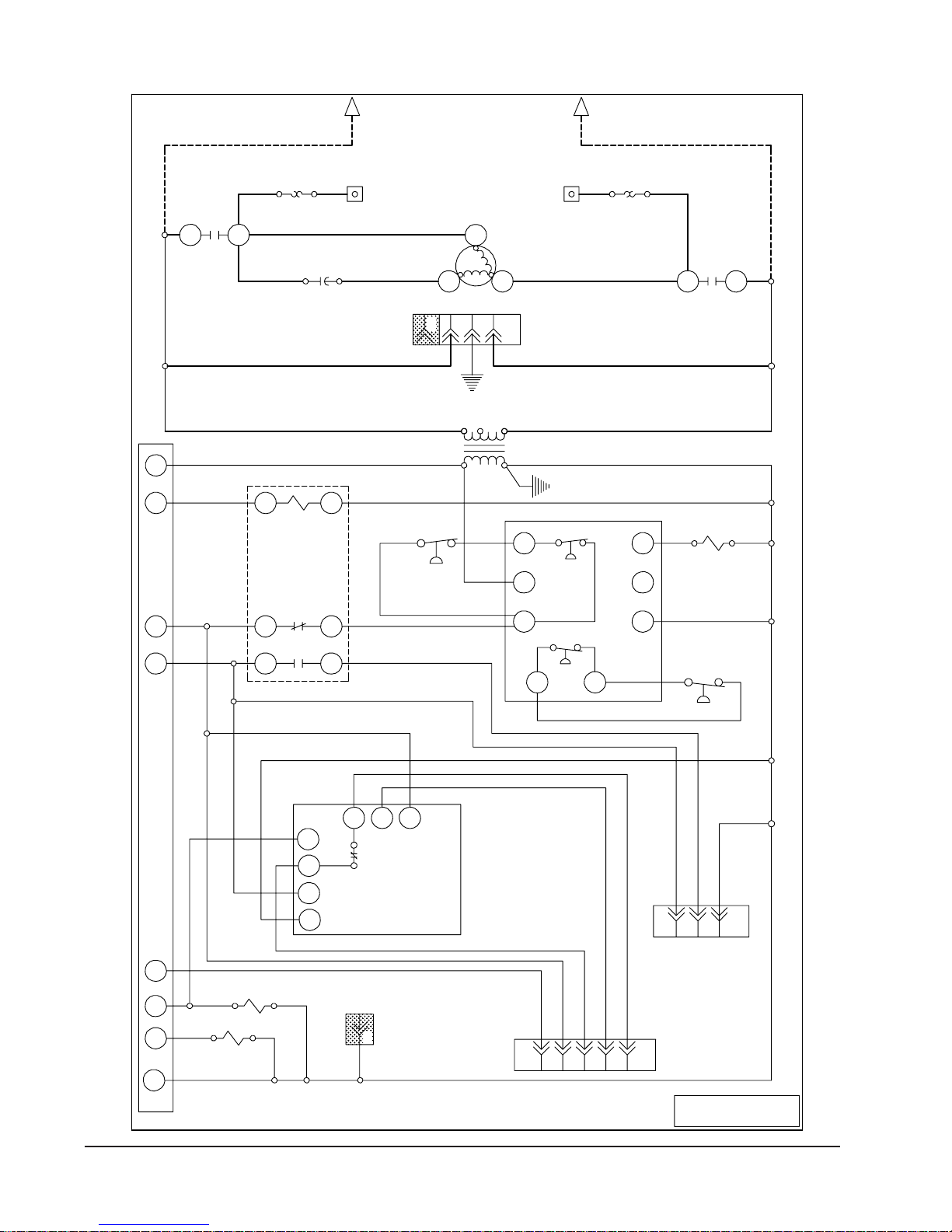
Line 1
230/208-60-1
Power Source
Line 2
Circuit
Breaker
L1
T1
Circuit
Breaker
Terminal
Block
Terminal
Block
R
Compressor
S
C
L2T2
Capacitor
C
240
GL1 L2
208
Transformer
R
E
13
High Pressure
24VAC
Control
Emergency
Heat Relay
4 Pin Plug for
Indoor Blower Motor
COM
HPC
R
CC
ALR
Compressor
Contactor
Y1
W2
G
Y2
O
C
Low Voltage Term. Strip
56
2
Y2
4
W
C
High Speed Solenoid
Reversing
Valve
4
53Y1
5
4
4 Pin Indoor
Blower Motor Plug
C
Blower
Control
Y
LPC
LPC
C
Comp.
Control
Module
Low Pressure
Control
321
3 Pin Heater
Package Plug
3124 5
5 Pin Indoor
Blower Motor Plug
Manual 2100-510E
Page 38 of 38
Ladder Diagram 4105-105
 Loading...