

Bard GSVS242-A, GSVS302-A, GSVS361-A, GSVS421-A, GSVS481-A Installation Instructions Manual
...Page 1
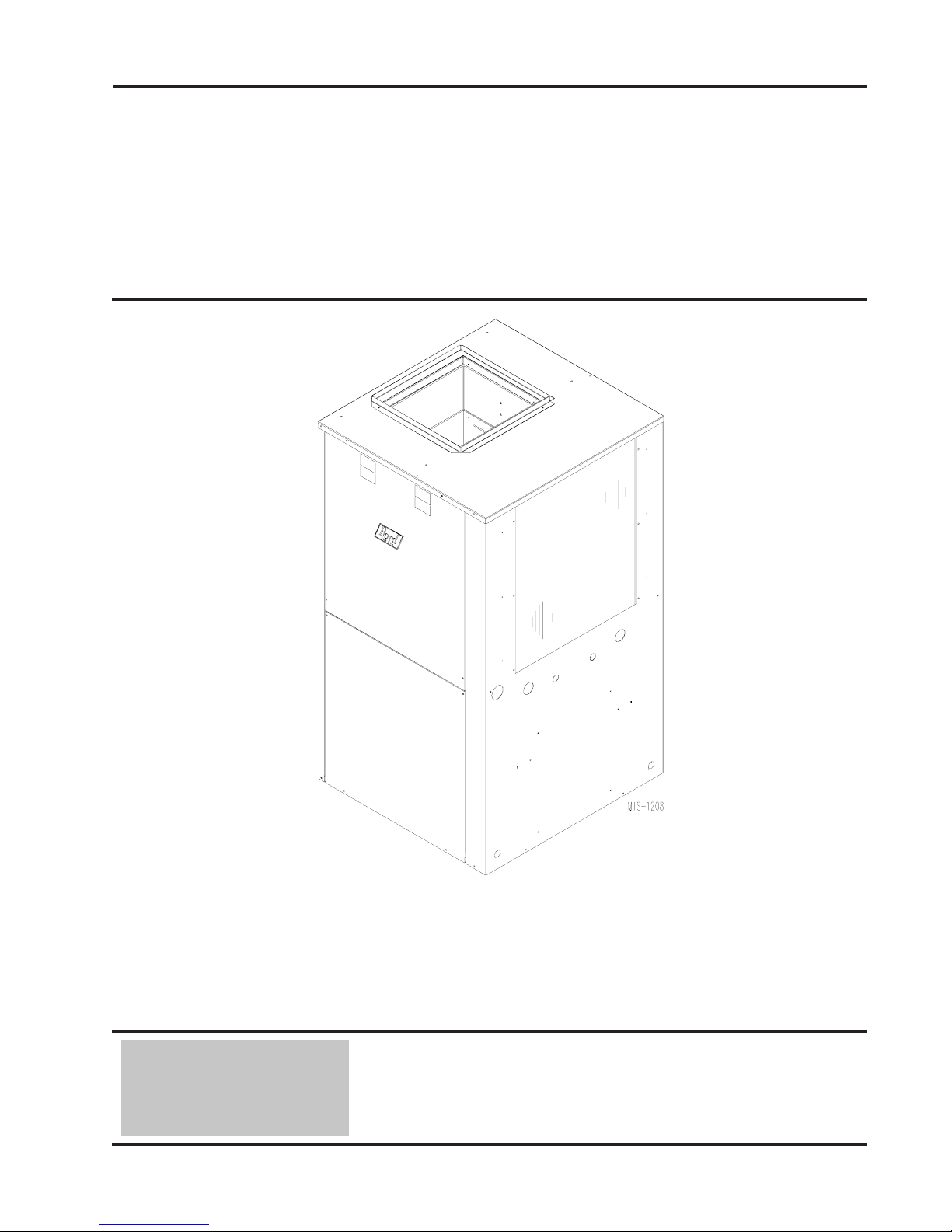
INSTALLATION
INSTRUCTIONS
WATER SOURCE
HEAT PUMPS
Models:
GSVS242-A, GSVS302-A
GSVS361-A, GSVS421-A
GSVS481-A, GSVS601-A
Ground Water Temperatures 45° - 75°
Earth Loop Fluid
Temperatures 25° - 110°
Bard Manufacturing Company, Inc.
Bryan, Ohio 43506
Since 1914...Moving ahead, just as planned.
Manual: 2100-317J
Supersedes: 2100-317
File: Volume I, Tab 8
Date: 05-16-08
Manual 2100-317J
Page 1 of 39
I
Page 2

CONTENTS
Getting Other Informations and Publications ........ 3
General Information
Water Source Nomenclature ................................... 4
Heater Package Nomenclature ............................... 8
Application and Location
General ................................................................ 9
Shipping Damage .................................................... 9
Application ............................................................... 9
Location ................................................................ 9
Ductwork ................................................................ 9
Filters ............................................................... 11
Condensate Drain ................................................... 11
Piping Access to Unit..............................................11
Wiring Instructions
General .............................................................. 13
Control Circuit Wiring ............................................ 13
Wall Thermostats................................................... 13
Thermostat Indicators ............................................ 14
Emergency Heat Mode .......................................... 14
Blower Control Setup ............................................. 14
Humidity Control .................................................... 14
CFM Light .............................................................. 14
Wiring Diagrams ............................................ 16 & 17
Closed Loop (Earth Coupled Ground Loop Applications)
Note .............................................................. 18
Circulation System Design .................................... 18
Start Up Procedure for Closed Loop System ......... 19
Open Loop (Well System Applications)
Note .............................................................. 21
Water Connection .................................................. 21
Well Pump Sizing .......................................... 21 & 22
Start Up Procedure for Open Loop System ........... 23
Water Corrosion ............................................ 23 & 24
Remedies of Water Problems................................ 24
Lake and/or Pond Installations ...................... 24 & 25
Sequence of Operation
Blower .............................................................. 26
Cooling .............................................................. 26
Heating Without Electric Heat ............................... 26
Heating With Electric Heat .................................... 26
Emergency Heat .................................................... 26
Lockout Circuits ..................................................... 26
Pressure Service Ports .......................................... 26
System Start Up..................................................... 26
Pressure Tables ................................................ 29-30
Quick Reference Troubleshooting Chart ............... 31
Service
Service Hints ......................................................... 32
Unbrazing System Components ............................ 32
Troubleshooting GE ECM™ Motors .............. 33 & 34
Accessories
Add-On DPM26A Pump Module Kit ....................... 35
General .............................................................. 35
Installation ............................................................. 35
Ground Source Heat Pump
Performance Report .......................................... 36-37
Figures
Figure 1 Unit Dimensions ...................................... 7
Figure 2 Field-Conversion to Left Hand Return .. 10
Figure 3A Filter Components GSVS24-42 Models .11
Figure 3B Filter Components GSVS48-60 Models .11
Figure 4 Piping Access ....................................... 12
Figure 5 Blower Control Board ............................ 15
Figure 6 Circulation System Design .................... 18
Figure 7 .............................................................. 20
Figure 8 Model GPM-1 Loop Pump Module ........ 20
Figure 9 Model GPM-2 Loop Pump Module ........ 20
Figure 10 Water Connection Components ............ 22
Figure 11 Cleaning Water Coil .............................. 24
Figure 12 Lake or Pond Installation ...................... 25
Figure 13 .............................................................. 27
Figure 14 Control Panel ........................................ 27
Figure 15 .............................................................. 28
Figure 16 Pressure Table Cooling ......................... 29
Figure 16A Pressure Table Heating ....................... 30
Figure 17 Control Disassembly ............................. 34
Figure 18 Winding Test .......................................... 34
Figure 19 Drip Loop ............................................... 34
Figure 20 Typical Pump Kit Connection (DPM26A) ..... 35
Manual 2100-317J
Page 2 of 39
Wiring Diagrams ................................................ 38-39
Tables
Table 1 Indoor Blower Performance .................... 4
Table 2 Flow Rates for Various Fluids ................. 5
Table 3 Specifications .......................................... 5
Table 4 Water Coil Pressure Drop ....................... 6
Table 5 Electrical Specifications Optional Field
Installed Heater Package ........................ 8
Table 6 Control Circuit Wiring ............................ 13
Table 7 Wall Thermostat .................................... 13
Table 8 Blower Control Setup ............................ 14
Table 9 Constant Flow Valves ........................... 21
Page 3

GETTING OTHER INFORMATION AND PUBLICATIONS
These publications can help you install the air
conditioner or heat pump. You can usually find these at
your local library or purchase them directly from the
publisher. Be sure to consult current edition of each
standard.
National Electrical Code ...................... ANSI/NFPA 70
Standard for the Installation .............. ANSI/NFPA 90A
of Air Conditioning and Ventilating Systems
Standard for Warm Air ...................... ANSI/NFPA 90B
Heating and Air Conditioning Systems
Load Calculation for Residential ....... ACCA Manual J
Winter and Summer Air Conditioning
Duct Design for Residential ............. ACCA Manual D
Winter and Summer Air Conditioning and Equipment
Selection
Closed-Loop/Ground Source Heat Pump ........ IGSHPA
Systems Installation Guide
Grouting Procedures for Ground-Source ......... IGSHPA
Heat Pump Systems
Soil and Rock Classification for ...................... IGSHPA
the Design of Ground-Coupled Heat Pump Systems
Ground Source Installation Standards ............. IGSHPA
Closed-Loop Geothermal Systems .................. IGSHPA
– Slinky Installation Guide
FOR MORE INFORMATION, CONTACT
THESE PUBLISHERS:
ACCA Air Conditioning Contractors of America
1712 New Hampshire Avenue
Washington, DC 20009
Telephone: (202) 483-9370
Fax: (202) 234-4721
ANSI American National Standards Institute
11 West Street, 13th Floor
New York, NY 10036
Telephone: (212) 642-4900
Fax: (212) 302-1286
ASHRAE American Society of Heating Refrigerating,
and Air Conditioning Engineers, Inc.
1791 Tullie Circle, N.E.
Atlanta, GA 30329-2305
Telephone: (404) 636-8400
Fax: (404) 321-5478
NFPA National Fire Protection Association
Batterymarch Park
P.O. Box 9101
Quincy, MA 02269-9901
Telephone: (800) 344-3555
Fax: (617) 984-7057
IGSHPA International Ground Source
Heat Pump Association
490 Cordell South
Stillwater, OK 74078-8018
Manual 2100-317J
Page 3 of 39
Page 4
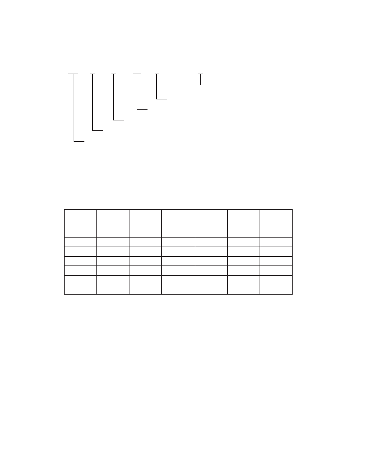
WATER SOURCE PRODUCT LINE NOMENCLATURE
GS V S 36 1- A
Modification Code
Approximate Capacity Size On High Speed
S = Single Capacity Compressor
V = Vertical
Ground Source Heat Pump
Electrical Characteristics
A = 230/208-60-1
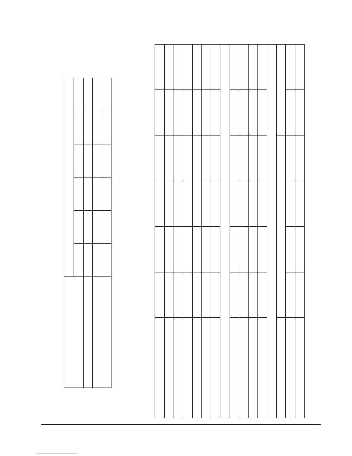
TABLE 1
1
INDOOR BLOWER PERFORMANCE (RATED CFM)
2
LEDOM
242SVSG01.006.00050080080001
203SVSG51.006.0055000100010001
163SVSG51.006.0526002100210521
124SVSG02.006.0576052105210521
184SVSG02.006.0008004100410091
106SVSG02.006.0009006100610091
detaR
PSE
XAM
PSE
suounitnoC
wolfriA
3
4
detaR
gnilooC
MFC
detaR
gnitaeH
MFC
cirtcelE
taeH
MFC
1 Motor will deliver consistent CFM through voltage supply range with no deterioration
(197-253V for all 230/208V models).
2 Continuous CFM is the total air being circulated during continuous (manual fan) mode.
3 Will occur automatically with a call for “Y” for cooling mode operation.
4 Will occur automatically with a call for “W1” for heating mode operation.
EXCEPTION: The rated CFM maybe adjusted +/- 15%, see Table 8. The CFM light on the Blower Control
Board can also be used to “count” the CFM of delivered air, see section on CFM light.
Manual 2100-317J
Page 4 of 39
Page 5
SLEDOM
TABLE 2
FLOW RATES FOR VARIOUS FLUIDS
A-242SVSGA-203SVSGA-163SVSGA-124SVSGA-184SVSGA-106SVSG
56789 21
edirolhCmuidoS%51MPGderiuqeretarwolF
retawhserfMPGderiuqeretarwolF 345568
SDIULFSUOIRAV
4SG%52MPGderiuqeretarwolF 56789 21
TABLE 3
SPECIFICATIONS
)HPV/Z06(gnitaRlacirtcelE1-802/0321-802/0321-802/0321-802/0321-802/0321-802/032
egnaRegatloVgnitarepO791-352791-352791-352791-352791-352791-352
LEDOMA-242SVSGA-203SVSGA-163SVSGA-124SVSGA-184SVSGA-106SVSG
hcnIrePsniF/swoR/.tF.qSaerAecaF51/3/61.351/3/61.311/4/61.311/4/61.311/3/33.511/4/33.5
tnerruCnoitceleStiucriChcnarB0.010.115.310.615.810.52
MFC/spmA–rotoMrewolB008/6.10001/3.20021/9.20521/5.30041/5.20061/5.3
yticapmAtiucriCmuminiM0.510.710.020.420.620.53
802/032spmAtinUlatoT1.9/1.88.11/8.015.41/9.311.91/7.7112/0282/72
ROSSERPMOC
802/032spmAdaoLdetaR5.7/5.65.9/5.86.11/0.116.51/2.415.81/5.716.42/5.32
stloV802/032802/032802/032802/032802/032802/032
802/032spmArotoRkcoL54/5445/455.27/5.2788/88901/901961/961
.dpS/PH–rotoMrewolB elbairaV/2/1elbairaV/4/3
ROTOMREWOLBdnaROTAROPAVE
+ 75°C copper wire ++ HACR type circuit breaker
+eziSeriWdleiF41#41#21#01#01#8#
++rekaerBtiucriCroxaMesuFyaleD025203530455
Manual 2100-317J
Page 5 of 39
Page 6
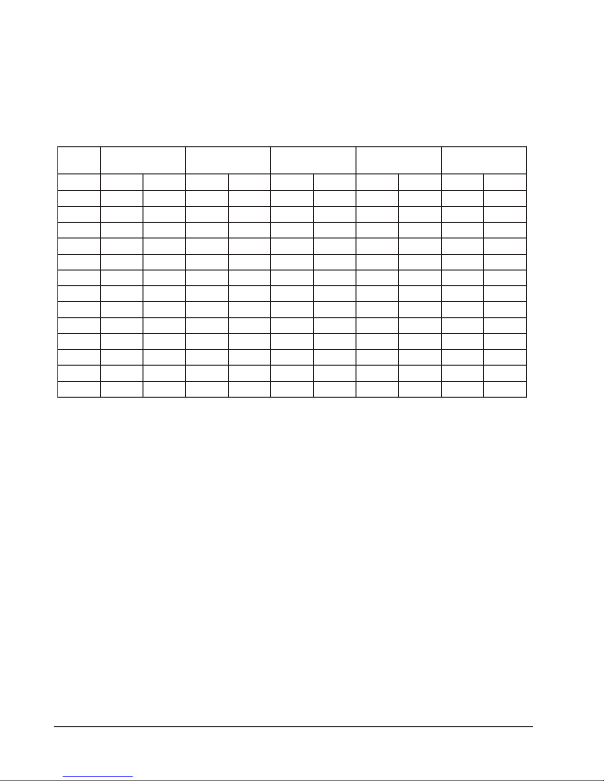
TABLE 4
WATER COIL PRESSURE DROP
,163SVSG
ledoM242SVSG203SVSG
MPGGISP.dH.tFGISP.dH.tFGISP.dH.tFGISP.dH.tFGISP.dH.tF
300.113.2------------------------
424.182.300.113.2------------------
538.122.434.103.308.151.4------------
642.271.568.192.482.375.778.226.6------
766.241.603.213.577.410.1133.400.01-----8------37.203.662.664.4157.582.31-----9------------57.709.7121.744.6158.398.8
01------------42.943.1244.805.9177.410.11
11------------------27.954.2296.541.31
21------------------59.0192.5216.662.51
31------------------------25.773.71
41------------------------34.874.91
51------------------------43.975.12
124SVSG184SVSG106SVSG
Manual 2100-317J
Page 6 of 39
Page 7
R
S
MIS-1886
4/3-32224/1-128/1-94/1-44/3-561/1-2
8/5-324/3-12128/5-64/1-44/3-58/7-1
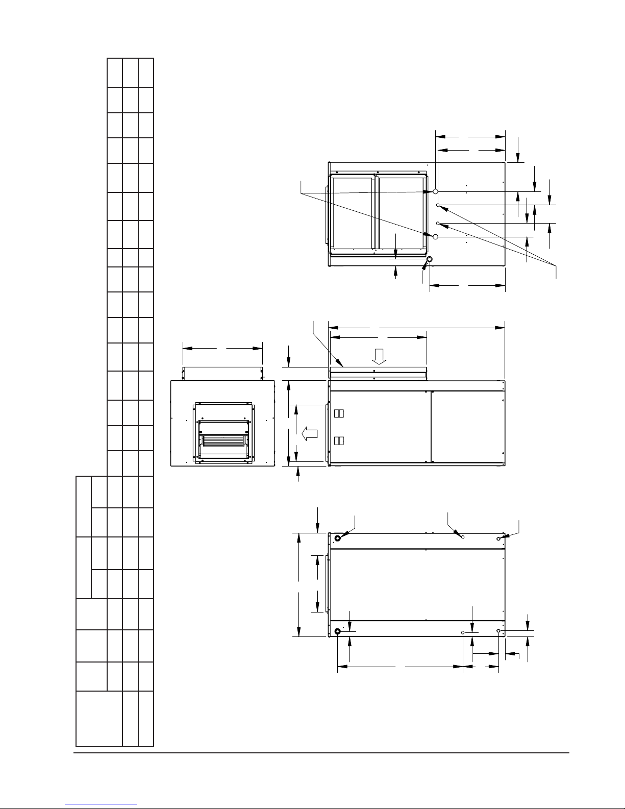
FIGURE 1 – UNIT DIMENSIONS
WATER PIPING
CONNECTIONS
3/4" OR 1" FPT
W
DRAIN
RETURN AIR
FILTER RACK
I
F
B
E
SUPPLY AIR
C
G
3/4" FPT
Q
T
U
V
U
DOMESTIC HOT WATER
HEAT EXCHANGER
WATER CONNECTIONS
J
LOW
VOLTAGE
OPTIONAL
HEATER
PACKAGE
ELECTRICAL
OPENING
H
INLET
UNIT
ELECTRICAL
OPENING
ylppuSnruteR
tcuDegnalFhtdiWthgieH
D
A
N
L
O
P
htdiWhtpeDthgieH
8/5-7262848/7-318/7-312/1-224/1-228/7-64/1-42/1-1234/1-118/5-14/1-14/3-12
8/5-23728/5-558/7-718/7-714/1-524/1-0374/1-42/1-14/1-934/1-118/5-14/1-14/3-12
M
K
ABCDEFGHIJKLMNOPQRSTUVW
24-42SVSG
06-84SVSG
stinU
Manual 2100-317J
Page 7 of 39
Page 8
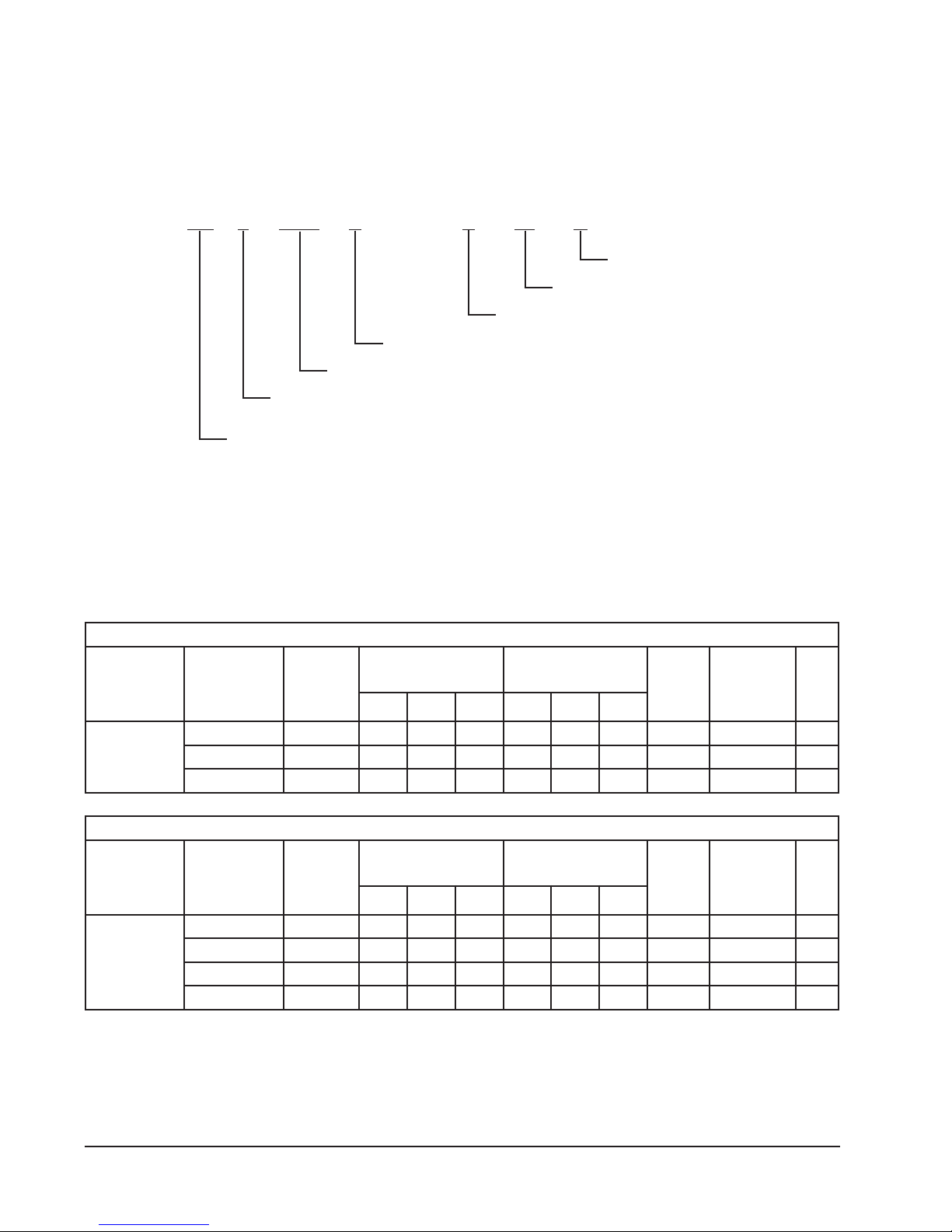
HEATER PACKAGE NOMENCLATURE
EH 3 GSV A- A 14 C
Modification Code
GSV = Ground Source Vertical
3 = 3 Ton
5 = 5 Ton
Electric Heater
ELECTRICAL SPECIFICATIONS
htiwesUroF
sledoMSVSG
,A-42SVSG
A-63,A-03
A-24dna
retaeH
egakcaP
.oNledoM
C50A-AVSG3HE1-802/0428.815.4543,513.6183.3525,115.325201
C90A-AVSG3HE1-802/0425.730.9096,035.2357.6810,329.64058
C41A-AVSG3HE1-802/0423.655.31530,647.8431.01345,434.07084
retaeH
egakcaP
esahP/stloV
ZH06
SPMAWKUTBSPMAWKUTB
TABLE 5
Nominal KW
A = 240/208-1-60
dnaWK,spmAretaeH
stloV042@yticapaC
C = Circuit Breaker
)ylnO24-63-03-42SVSG(segakcaPretaeHdellatsnI-dleiFlanoitpO-snoitacificepSlacirtcelE
dnaWK,spmAretaeH
stloV802@yticapaC
muminiM
tiucriC
yticapmA
mumixaM
RCAH
tiucriC
rekaerB
dleiF
eriW
+eziS
htiwesUroF
sledoMSVSG
A-84SVSG
A-06dna
+ Based on 75F copper wire. All wiring must conform to National Electrical Code (latest edition) and all local codes.
retaeH
egakcaP
.oNledoM
C50A-AVSG5HE1-802/0428.815.4543,513.6183.3525,115.325201
C90A-AVSG5HE1-802/0425.730.9096,035.2357.6810,329.64058
C41A-AVSG5HE1-802/0423.655.31530,647.8431.01345,434.07084
C81A-AVSG5HE1-802/0420.570.81083,169.465.31530,643.890013
Manual 2100-317J
Page 8 of 39
)ylnO06-84SVSG(segakcaPretaeHdellatsnI-dleiFlanoitpO-snoitacificepSlacirtcelE
retaeH
egakcaP
esahP/stloV
ZH06
SPMAWKUTBSPMAWKUTB
dnaWK,spmAretaeH
stloV042@yticapaC
dnaWK,spmAretaeH
stloV802@yticapaC
muminiM
tiucriC
yticapmA
mumixaM
RCAH
tiucriC
rekaerB
dleiF
eriW
+eziS
Page 9

APPLICATION AND LOCATION
GENERAL
Units are shipped completely assembled and internally
wired, requiring only duct connections, thermostat
wiring, 230/208 volt AC power wiring, and water
piping. The equipment covered in this manual is to be
installed by trained, experienced service and installation
technicians. Any heat pump is more critical of proper
refrigerant charge and an adequate duct system than a
cooling only air conditioning unit.
These instructions and any instructions packaged with
any separate equipment required to make up the entire
heat pump system should be carefully read before
beginning the installation. Note particularly any tags
and/or labels attached to the equipment.
While these instructions are intended as a general
recommended guide, they do not in any way supersede
any national and/or local codes. Authorities having
jurisdiction should be consulted before the installation
is made.
SHIPPING DAMAGE
Upon receipt of the equipment, the carton should be
checked for external signs of shipping damage. If
damage is found, the receiving party must contact the
last carrier immediately, preferably in writing,
requesting inspection by the carrier’s agent.
APPLICATION
Capacity of the unit for a proposed installation should
be based on heat loss calculations made in accordance
with methods of the Air Conditioning Contractors of
America, formerly National Warm Air Heating and Air
Conditioning Association. The air duct system should
be sized and installed in accordance with Standards of
the National Fire Protection Association for the
Installation of Air Conditioning and Venting systems of
Other than Residence Type NFPA No. 90A, and
residence Type Warm Air Heating and Air Conditioning
Systems, NFPA No. 90B.
compressor compartment and re-securing the control
panel on the opposite side of the water coil. (See Figure
2.) The two (2) access doors from the right hand return
can be transferred to the left-hand return side and the
one (1) left hand panel can be transferred to the right
hand side.
Unit casing suitable for 0 inch clearance with 1-inch
duct clearance for at least the first 4 feet of duct. These
units are not approved for outdoor installation and
therefore must be installed inside the structure being
conditioned. Do not locate in areas subject to freezing
in the winter or subject to sweating in the summer.
Before setting the unit, consider ease of piping, drain
and electrical connections for the unit. Also, for units
which will be used with a field installed heat recovery
unit, consider the proximity of the unit to the water
heater or storage tank. Place the unit on a solid base,
preferably concrete, to minimize undesirable noise and
vibration. DO NOT elevate the base pan on rubber or
cork vibration eliminator pads as this will permit the
unit base to act like a drum, transmitting objectionable
noise.
DUCTWORK
If the unit is to be installed in a closet or utility room
which does not have a floor drain, a secondary drain pan
under the entire unit is highly recommended.
DO NOT install the unit in such a way that a direct path
exists between any return grille and the unit. Rather,
insure that the air entering the return grille will make at
least one turn before entering the unit or coil. This will
reduce possible objectionable compressor and air noise
from entering the occupied space.
Design the ductwork according to methods given by the
Air Conditioning Contractors of America. When duct
runs through unconditioned spaces, it should be
insulated with vapor barrier. It is recommended that
flexible connections be used to connect the ductwork to
the unit in order to keep the noise transmission to a
minimum.
LOCATION
The unit may be installed in a basement, closet, or
utility room provided adequate service access is insured.
The unit is shipped from the factory as a right hand
return and requires access clearance of two feet
minimum to the access panels on this side of the
unit. If unit is to be field converted to left hand return
the opposite side will require access clearance of two
feet minimum.
Unit may be field converted to left hand return by
removing four (4) screws that secure the control panel
cover, removing two (2) screws that hold the control
panel in place, sliding the control panel through the
WARNING
Failure to provide the 1-inch clearance
between the supply duct and a combustible
surface for the first 3 feet of duct can result in
a fire.
Manual 2100-317J
Page 9 of 39
Page 10
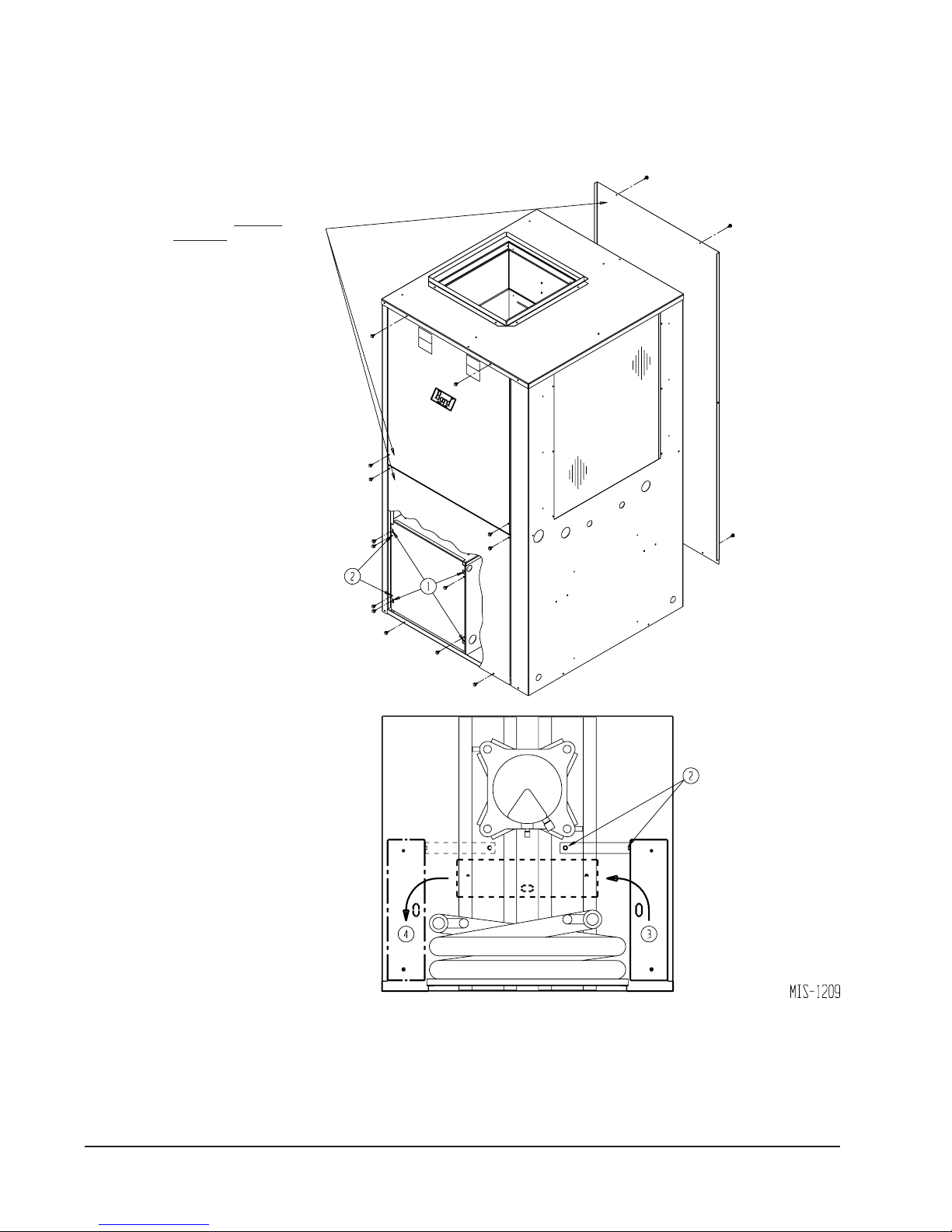
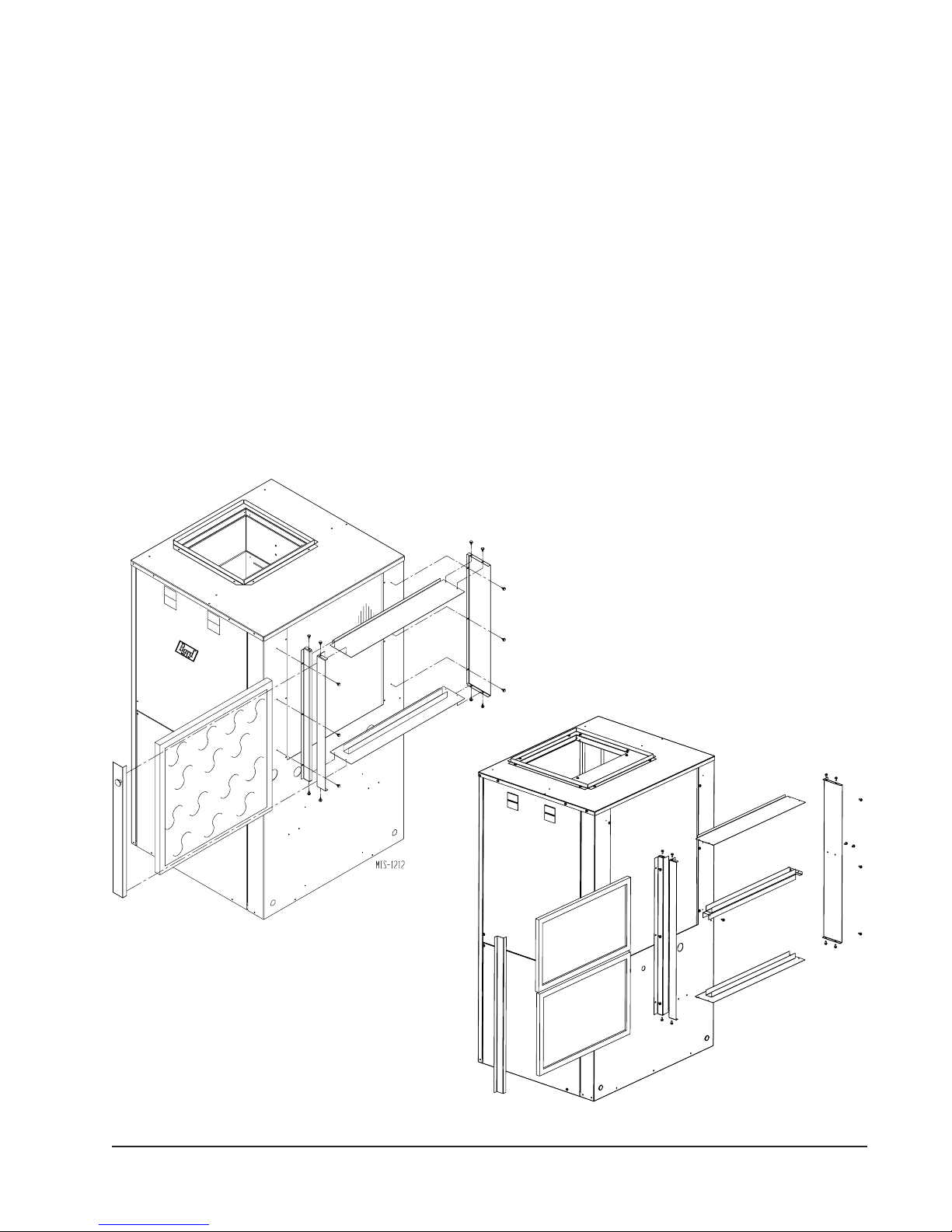
FIELD-CONVERSION TO LEFT HAND RETURN
REMOVE SINGLE AND
DOUBLE DOORS
1 REMOVE 4 SCREWS SECURING
COVER
2 REMOVE 2 SCREWS HOLDING
CONTROL BOX TO CORNER PANEL
REMOVE 2 SCREWS SECURING
PANEL TO BASE.
3 PASS CONTROL PANEL THROUGH
COMPRESSOR SECTION
4 RE-SECURE CONTROL PANEL ON
OPPOSITE SIDE IN SAME MANNER
AS ORIGINALLY ATTACHED
FIGURE 2
REPOSITION DOORS SO DOUBLE DOORS
ARE ON CONTROL PANEL SIDE, AND
SINGLE DOOR ON OPPOSITE SIDE
Manual 2100-317J
Page 10 of 39
TOP VIEW
Page 11
FILTER
This unit must not be operated without a filter. It comes
equipped with disposable filters, which should be
checked often and replaced if dirty. Insufficient airflow
due to undersized duct systems or dirty filters can result
in nuisance tripping of the high or low pressure control.
Refer to Table 2 for correct airflow and static pressure
requirements. (See Figures 3A & 3B.)
filled with water prior to start up. The use of plugged
tees in place of elbows to facilitate cleaning is highly
recommended.
Drain lines must be installed according to local
plumbing codes. It is not recommended that any
condensate drain line be connected to a sewer main.
The drain line enters the unit through the 3/4" FPT
coupling on the coil side of the unit.
CONDENSATE DRAIN
Determine where the drain line will run. This drain line
contains cold water and must be insulated to avoid
droplets of water from condensing on the pipe and
dripping on finished floors or the ceiling under the unit.
A trap MUST BE installed in the drain line and the trap
FIGURE 3A
GSVS24 - 42 MODELS
PIPING ACCESS TO UNIT
Water piping to and from the unit enters the unit casing
from the coil side of the unit under the return air filter
rack. Piping connections are made directly to the unit
and are 3/4" FPT for models 24 - 42, and 1" FPT for
models 48-60. (See Figure 4.)
FIGURE 3B
GSVS48 - 60 MODELS
MIS-1888
Manual 2100-317J
Page 11 of 39
Page 12
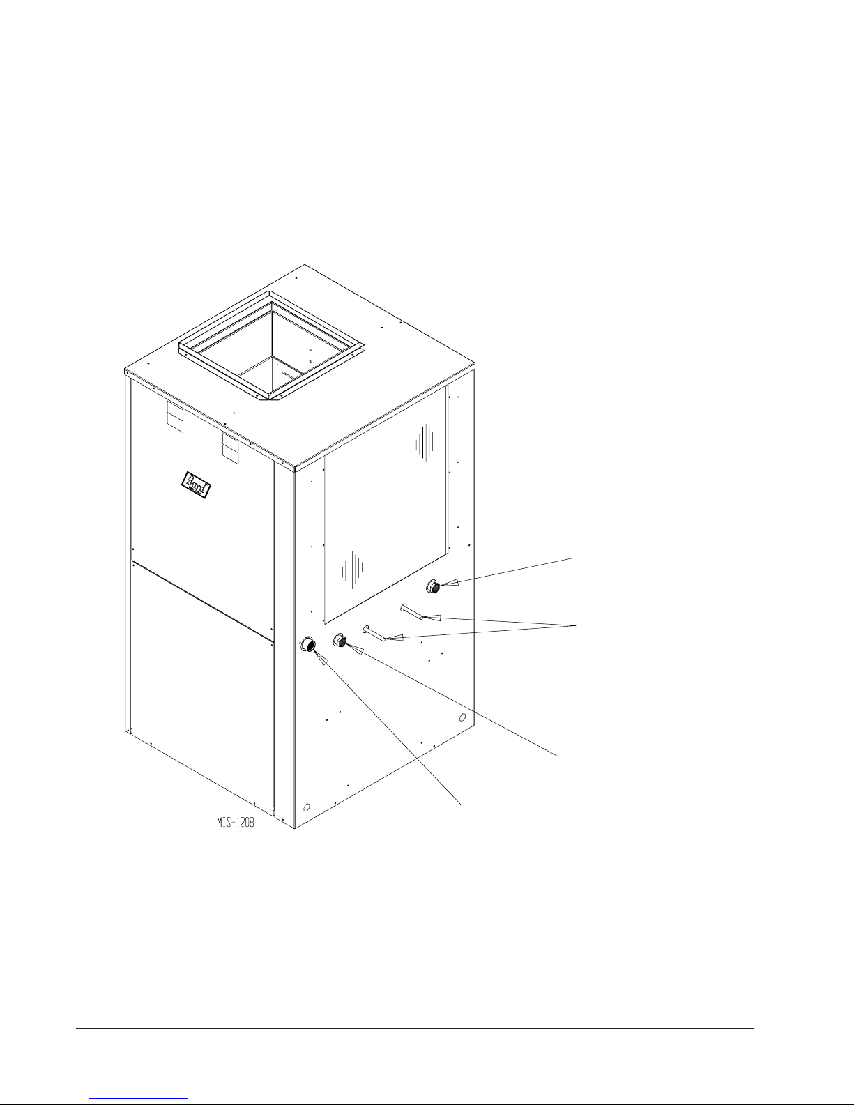
FIGURE 4
PIPING ACCESS TO UNIT
WATER “IN” CONNECTION
3/4" FPT GSVS24-42 MODELS
1" FPT GSVS48-60 MODELS
WATER “OUT” CONNECTION
3/4" FPT GSVS24-42 MODELS
1" FPT GSVS48-60 MODELS
CONDENSATE DRAIN
3/4" FPT
PUMP MODULE CONNECTIONS
1/2" COPPER STUB
Manual 2100-317J
Page 12 of 39
Page 13

WIRING INSTRUCTIONS
GENERAL
All wiring must be installed in accordance with the
National Electrical Code and local codes. In Canada,
all wiring must be installed in accordance with the
Canadian Electrical Code and in accordance with the
regulations of the authorities having jurisdiction. Power
supply voltage must conform to the voltage shown on
the unit serial plate. A wiring diagram of the unit is
attached to the inside of the electrical cover. The power
supply shall be sized and fused according to the
specifications supplied. A ground lug is supplied in the
control compartment for equipment ground.
The unit rating plate lists a Maximum Time Delay
Fuse” or “HACR” type circuit breaker that is to be used
with the equipment. The correct size must be used for
proper circuit protection and also to assure that there
will be no nuisance tripping due to the momentary high
starting current of the compressor motor.
CONTROL CIRCUIT WIRING
The minimum control circuit wiring gauge needed to
insure proper operation of all controls in the unit will
depend on two factors.
TABLE 6
CONTROL CIRCUIT WIRING
foAVdetaR
tiucriClortnoC
remrofsnarT
051.2
remrofsnarT
yradnoceS
V42@ALF
foecnatsiD
Example: 1. Control Circuit transformer rated at 50 VA
2. Maximum total distance of control circuit
wiring 85 feet.
From Table 6 minimum of 16 gauge wire
should be used in the control circuit wiring.
WALL THERMOSTATS
The following wall thermostats and subbases should be
used as indicated, depending on the application.
latoTmumixaM
tiucriClortnoC
teeFnigniriW
54-eguag02
06-eguag81
001-eguag61
061-eguag41
052-eguag21
1. The rated VA of the control circuit transformer.
2. The maximum total distance of the control circuit
wiring.
Table 6 should be used to determine proper gauge of
control circuit wring required.
WALL THERMOSTAT
tatsomrehTserutaeFtnanimoderP
850-3048
)1511D0225HT(
060-3048
)544-0211(
TABLE 7
taeHegats2;looCegats2
elbammargorP-noNcinortcelE
revoegnahclaunaMrootuA
taeHegats3;looCegats3
cinortcelEelbammargorP-noN/elbammargorP
lanoitnevnoCroPH
revoegnahclaunaMrootuA
Manual 2100-317J
Page 13 of 39
Page 14

THERMOSTAT INDICATORS
8403-058 (TH5220D1151) Thermostat:
Thermostat will display on the screen “Em Heat” when
the thermostat is set on emergency heat.
8403-060 (1120-445) Temperature/Humidity Control:
In heating or cooling, the display may be black and light
gray, or backlit in blue depending on configuration. In
the event of a system malfunction such as a loss of
charge or high head pressure, the heat pump control
board will issue a signal to the thermostat causing the
screen to be backlit in RED and the display to read
“Service Needed”. If this occurs, the control will
continue to function, but you will not be able to make
any adjustments until the problem is corrected and the
fault device is reset.
EMERGENCY HEAT MODE
The operator of the equipment must manually place the
system switch in this mode. This is done when there is
a known problem with the unit.
When the 8403-060 (1120-445) Temperature/Humidity
Control is placed in the Emergency Heat mode, the
display will be backlit in RED to indicate that service is
needed. The display will remain backlit in red until the
mode is switched out of Emergency Heat.
BLOWER CONTROL SETUP
Due to the unique functions that the ECM blower motor
is able to perform each installation requires that the
jumpers on the blower control board be checked and
possibly moved based on the final installation. (See
Figure 5.) Check Table 8 to verify the ADJUST,
HEAT, COOL, and DELAY taps are set in the proper
location for the installation.
HUMIDITY CONTROL
With the use of optional humidistat 8403-038 cut
jumper on blower control board marked “cut to enable”
(refer to on Figure 5) to allow the humidistat to
reduce the blower airflow in the dehumidify mode. By
reducing the airflow about 15% the air coil runs colder
and thus extracts more moisture. This can increase
latent capacity from 5 to 13% based on the R/H
conditions of the structure being conditioned. Refer to
control circuit diagram for wiring of humidistat.
CFM LIGHT
The light marked CFM on the blower control board
(refer to on Figure 5) alternates between blinking 1
second per approximately 100 CFM of air delivered by
the blower, and a solid light with 1 second off period
between modes.
.1tsujdA
.2taeH
.3looC
.4yaleD
TABLE 8
BLOWER CONTROL SETUP
mroN
-
)+(
-
)-(
-
tseT
-
.A
-
Wk0deppihstinuhtiwnoitisopsihtnirepmuj
.B
-
Wk5.4noitisopsihtnirepmujdellatsniegakcapretaeh
.C
-
.D
-
.A
-
.B
-
.C
-
.D
-
.A
-
.B
-
.C
-
.D
-
.noitacilppasihtnidesutoN
noitacilppasihtnidesutoN
noitacilppasihtnidesutoN
noitisopsihtnirepmujhtiwdeppihstinU
%51wolfriasesaercninoitisopsihtnirepmuJ
%51wolfriasesaercednoitisopsihtnirepmuJ
noitisopsihtnirepmujdellatsniegakcapretaehWk9
noitisopsihtnirepmujdellatsniegakcapretaehWk41
noitisopsihtnirepmujhtiwdeppihstinU
dellatsniegakcapretaehynanehwnoitisopsihtnirepmuJ
noitisopsihtnirepmujhtiwdeppihstinuyaledoN
wolfria%65htiwnwodtuhsnoyaledrewolb.nim1
yaledBpatsulpwolfria%57htiwtratsnonurtrohs.nim2/12
yaledCdnaBpatsulpwolfria%83htiwtratsnonur-erp.nim1
Manual 2100-317J
Page 14 of 39
Page 15

SEE HUMIDITY
CONTROL
FIGURE 5
BLOWER CONTROL BOARD
SEE TABLE 8
SEE TABLE 8
SEE TABLE 8
SEE TABLE 8
SEE CFM LIGHT
Manual 2100-317J
Page 15 of 39
Page 16

Manual 2100-317J
Page 16 of 39
Page 17

Manual 2100-317J
Page 17 of 39
Page 18

CLOSED LOOP
(EARTH COUPLED GROUND LOOP APPLICATIONS)
NOTE:
Unit shipped from factory with 27 PSIG low
pressure switch wired into control circuit and
must be rewired to 15 PSIG low pressure switch
for closed loop applications. This unit is designed
to work on earth coupled ground loop systems,
however, these systems operate at entering water
(without antifreeze) temperature with pressures
well below the pressures normally experienced in
water well systems.
THE CIRCULATION SYSTEM DESIGN
Equipment room piping design is based on years of
experience with earth coupled heat pump systems. The
design eliminates most causes of system failure.
Surprisingly, the heat pump itself is rarely the cause.
Most problems occur because designers and installers
forget that a closed loop earth coupled heat pump
system is NOT like a household plumbing system.
Most household water systems have more than enough
water pressure either from the well pump of the
municipal water system to overcome the pressure of
head loss in 1/2 inch or 3/4 inch household plumbing. A
closed loop earth coupled heat pump system, however,
is separated from the pressure of the household supply
and relies on a small, low wattage pump to circulate the
water and antifreeze solution through the earth coupling,
heat pump and equipment room components.
The small circulator keeps the operating costs of the
system to a minimum. However, the performance of the
circulator MUST be closely matched with the pressure
of head loss of the entire system in order to provide the
required flow through the heat pump. Insufficient flow
through the heat exchanger is one of the most common
causes of system failure. Proper system piping design
and circulator selection will eliminate this problem
Bard supplies a work sheet to simplify head loss
calculations and circulator selection. Refer to
“Circulating Pump Worksheet” section in manual
2100-099.
WATER OUT
PIPE TO GROUND LOOP
PIPE FROM
GROUND LOOP
HOSE CLAMPS
PUMP
MODULE
WATER
IN
BARB X INSERT
BRASS ADAPTERS
1" FLEXIBLE HOSE
FIGURE 6
CIRCULATION SYSTEM DESIGN
OPTIONAL VISUAL
FLOW METER
NOTE: IF USED
SUPPORT WITH A
FIELD-FABRICATED
WALL BRACKET
Manual 2100-317J
Page 18 of 39
Page 19

START UP PROCEDURE FOR CLOSED
LOOP SYSTEM
1. Be sure main power to the unit is OFF at disconnect.
2. Set thermostat system switch to OFF, fan switch to
AUTO.
3. Move main power disconnect to ON. Except as
required for safety while servicing, DO NOT OPEN
THE UNIT DISCONNECT SWITCH.
4. Check system airflow for obstructions.
A. Move thermostat fan switch to ON. Blower
runs.
B. Be sure all registers and grilles are open.
C. Move thermostat fan switch to AUTO. Blowing
should stop.
5. Flush, fill and pressurize the closed loop system as
outlined in manual 2100-099.
6. Fully open the manual inlet and outlet valves. Start
the loop pump module circulator(s) and check for
proper operation. If circulator(s) are not operating,
turn off power and diagnose the problem.
7. Check fluid flow using a direct reading flow meter
or a single water pressure gauge, measure the
pressure drop at the pressure/temperature plugs
across the water coil. Compare the measurement
with flow versus pressure drop table to determine
the actual flow rate. If the flow rate is too low,
recheck the selection of the loop pump module
model for sufficient capacity. If the module
selection is correct, there is probably trapped air or a
restriction in the piping circuit.
8. Start the unit in cooling mode. By moving the
thermostat switch to cool, fan should be set for
AUTO.
9. Check the system refrigerant pressures against the
cooling refrigerant pressure table in the installation
manual for rated water flow and entering water
temperatures. If the refrigerant pressures do not
match, check for airflow problem then refrigeration
system problem.
10. Switch the unit to the heating mode. By moving the
thermostat switch to heat, fan should be set for
AUTO.
11. Check the refrigerant system pressures against the
heating refrigerant pressure table in installation
manual. Once again, if they do not match, check for
airflow problems and then refrigeration system
problems.
NOTE: If a charge problem is determined (high or low):
A. Check for possible refrigerant leaks.
B. Recover all remaining refrigerant from unit and
repair leak.
C. Evacuate unit down to 29 inches of vacuum
D. Recharge the unit with refrigerant by weight.
This is the only way to insure a proper charge.
Manual 2100-317J
Page 19 of 39
Page 20

FIGURE 7
DIAL FACE PRESSURE GAUGE
WITH GAUGE ADAPTOR
PERFORMANCE MODEL GPM-1 LOOP PUMP MODULE
35
30
THERMOMETER
WATER COIL CONNECTION
AT HEAT PUMP
1" AND
3/4" MPT
BARB X INSERT
BRASS ADAPTER
SELF SEALING
PETE’S TEST PLUG
TEST PLUG CAP
FIGURE 8
25
20
15
Head (Feet)
10
5
0
0 5 10 15 20 25 30 35
Flow (GPM)
FIGURE 9
PERFORMANCE MODEL GPM-2 LOOP PUMP MODULE
70
60
50
40
30
Head (Feet)
20
10
0
0 5 10 15 20 25 30 35
Manual 2100-317J
Page 20 of 39
Flow (GPM)
Page 21

OPEN LOOP
(WELL SYSTEM APPLICATIONS)
NOTE:
Unit shipped from factory with 27 PSIG low
pressure switch wired into control circuit for
open loop applications.
WATER CONNECTIONS
It is very important that an adequate supply of clean,
noncorrosive water at the proper pressure be provided
before the installation is made. Insufficient water, in the
heating mode for example, will cause the low pressure
switch to trip, shutting down the heat pump. In
assessing the capacity of the water system, it is
advisable that the complete water system be evaluated
to prevent possible lack of water or water pressure at
various household fixtures whenever the heat pump
turns on. All plumbing to and from the unit is to be
installed in accordance with local plumbing codes. The
use of plastic pipe, where permissible, is recommended
to prevent electrolytic corrosion of the water pipe.
Because of the relatively cold temperatures encountered
with well water, it is strongly recommended that the
water lines connecting the unit be insulated to prevent
water droplets form condensing on the pipe surface.
Refer to piping, Figure 10. Slow closing Solenoid
Valve (6) with a 24 V coil provides on/off control of the
water flow to the unit. Refer to the wiring diagram for
correct hookup of the valve solenoid coil.
Constant Flow Valve (7) provides correct flow of water
to the unit regardless of variations in water pressure.
Observe the water flow direction indicated by the arrow
on the side of the valve body. Following is a table
showing which valve is the be installed with which heat
pump.
TABLE 9
CONSTANT FLOW VALVES
elbaliavA.niM
.oNtraP
700-3068)1(516
800-3068)1(518
010-3068)1(514
110-3068)1(515
910-3068)1(513
(1)
The pressure drop through the constant flow valve
will vary depending on the available pressure
ahead of the valve. Unless minimum of 15 psig
is available immediately ahead of the valve, no
water will flow.
GISPerusserP
etaRwolF
MPG
Strainer (5) installed upstream of constant flow valve
(7) to collect foreign material which would clog the flow
valve orifice.
The figure shows the use of shutoff valves (9) and (11),
on the in and out water lines to permit isolation of the
unit from the plumbing system should future service
work require this. Globe valves should not be used as
shutoff valves because of the excessive pressure drop
inherent in the valve design. Instead use gate or ball
valves as shutoffs, so as to minimize pressure drop.
Drain cock (8) and (10), and tees have been included to
permit acid cleaning the refrigerant-to-water coil should
such cleaning be required. See WATER CORROSION.
Drain cock (12) provides access to the system to check
water flow through the constant flow valve to insure
adequate water flow through the unit. A water meter is
used to check the water flow rate.
WELL PUMP SIZING
Strictly speaking, sizing the well pump is the
responsibility of the well drilling contractor. It is
important, however, that the HVAC contractor be
familiar with the factors that determine what size pump
will be required. Rule of thumb estimates will
invariably lead to under or oversized well pumps.
Undersizing the pump will result in inadequate water to
the whole plumbing system, but with especially bad
results to the heat pump – NO HEAT / NO COOL calls
will result. Oversized pumps will short cycle and could
cause premature pump motor or switch failures.
The well pump must be capable of supplying enough
water and at an adequate pressure to meet competing
demands of water fixtures. The well pump must be
sized in such a way that three requirements are met:
1. Adequate flow rate in GPM.
2. Adequate pressure at the fixture.
3. Able to meet the above from the depth of the
well-feet of lift.
Manual 2100-317J
Page 21 of 39
Page 22

The pressure requirements put on the pump are directly
affected by the diameter of pipe being used, as well as,
by the water flow rate through the pipe. The worksheet
included in manual 2110-078 should guarantee that the
well pump has enough capacity. It should also ensure
WATER CONNECTION COMPONENTS
that the piping is not undersized, which would create too
much pressure due to friction loss. High pressure losses
due to undersized pipe will reduce efficiency and
require larger pumps and could also create water noise
problems.
FIGURE 10
Manual 2100-317J
Page 22 of 39
10
11
5
8
9
6
7
12
Page 23

SYSTEM START UP PROCEDURE FOR
OPEN LOOP APPLICATIONS
1. Be sure main power to the unit is OFF at disconnect.
2. Set thermostat system switch to OFF, fan switch to
AUTO.
3. Move main power disconnect to ON. Except as
required for safety while servicing – DO NOT OPEN
THE UNIT DISCONNECT SWITCH.
4. Check system airflow for obstructions.
A. Move thermostat fan switch to ON. Blower runs.
B. Be sure all registers and grilles are open.
C. Move thermostat fan switch to AUTO. Blower
should stop.
5. Fully open the manual inlet and outlet valves.
6. Check water flow.
A. Connect a water flow meter to the drain cock
between the constant flow valve and the
solenoid valve. Run a hose from the flow meter
to a drain or sink. Open the drain cock.
B. Check the water flow rate through constant
flow valve to be sure it is the same as the unit
is rated for.
C. When water flow is okay, close drain cock and
remove the water flow meter. The unit is now
ready to start.
7. Start the unit in cooling mode. By moving the
thermostat switch to cool, fan should be set for
AUTO.
A. Check to see the solenoid valve opened.
8. Check the system refrigerant pressures against the
cooling refrigerant pressure table in the installation
manual for rated water flow and entering water
temperatures. If the refrigerant pressures do not
match, check for airflow problem that refrigeration
system problem.
(Example: 4 GPM for a GSVS302-A.)
WATER CORROSION
Two concerns will immediately come to light when
considering a water source heat pump, whether for
ground water or for a closed loop application: Will
there be enough water? And, how will the water quality
affect the system?
Water quantity is an important consideration and one
which is easily determined. The well driller must
perform a pump down test on the well according to
methods described by the Nation Well Water
Association. This test, if performed correctly, will
provide information on the rate of low and on the
capacity of the well. It is important to consider the
overall capacity of the well when thinking about a water
source heat pump because the heat pump may be
required to run for extended periods of time.
The second concern, about water quality, is equally
important. Generally speaking, if the water is not
offensive for drinking purposes, it should pose no
problem for the heat pump. The well driller or local
water softening company can perform tests which will
determine the chemical properties of the well water.
Water quality problems will show up in the heat pump
in one of more of the following ways:
1. Decrease in water flow through the unit.
2. Decreased heat transfer of the water coil (entering to
leaving water temperature difference is less).
There are four main water quality problems associated
with ground water. These are:
1. Biological Growth. This is the growth of
microscopic organisms in the water and will show
up as a slimy deposit throughout the water system.
Shock treatment of the well is usually required and
this is best left up to the well driller. The treatment
consists of injecting chlorine into the well casing
and flushing the system until all growth is removed.
9. Switch the unit to the heat mode. By moving the
thermostat switch to heat, fan should be set for
AUTO.
A. Check to see the solenoid valve opened again.
10. Check the refrigerant system pressures against the
heating refrigerant pressure table in installation
manual. Once again, if they do not match, check for
airflow problems and then refrigeration system
problems.
NOTE: If a charge problem is determined (high or low):
A. Check for possible refrigerant loss.
B. Discharge all remaining refrigerant from unit.
C. Evacuate unit down to 29 inches of vacuum.
D. Recharge the unit with refrigerant by weight.
This is the only way to insure proper charge.
2. Suspended Particles in the Water. Filtering will
usually remove most suspended particles (fine sand,
small gravel) from the water. The problem with
suspended particles in the water is that it will erode
metal parts, pumps, heat transfer coils, etc. So long
as the filter is cleaned and periodically maintained,
suspended particles should pose no serious problem.
Consult with your well driller.
3. Corrosion of Metal. Corrosion of metal parts
results from either highly corrosive water (acid
water, generally not the case with ground water) of
galvanic reaction between dissimilar metals in the
presence of water. By using plastic plumbing or
dielectric unions, galvanic reaction is eliminated.
The use of corrosion resistant materials such as the
Cupronickel coil) through the water system will
reduce corrosion problems significantly.
Manual 2100-317J
Page 23 of 39
Page 24

4. Scale Formation. Of all the water problems, the
formation of scale by ground water is by far the most
common. Usually this scale is due to the formation of
calcium carbonate by magnesium carbonate or
calcium sulfate may also be present. Carbon dioxide
gas (CO2), the carbonate of calcium and magnesium
carbonate, is very soluble in water. It will remain
dissolved in the water until some outside factor upsets
the balance. This outside influence may be a large
change in water temperature or pressure. When this
happens, enough carbon dioxide gas combines with
dissolved calcium or magnesium in the water and falls
out of solution until a new balance is reached. The
change in temperature that this heat pump produces is
usually not high enough to cause the dissolved gas to
fall out of solution. Likewise, if pressure drops are
kept to a reasonable level, no precipitation of carbon
dioxide should occur.
REMEDIES OF WATER PROBLEMS
Water Treatment. Water treatment can usually be
economically justified for close loop systems.
However, because of the large amounts of water
involved with a ground water heat pump, water
treatment is generally too expensive.
Acid Cleaning the Water Coil or Heat Pump
Recovery Unit. If scaling of the coil is strongly
suspected, the coil can be cleaned up with a solution of
Phosphoric Acid (food grade acid). Follow the
manufacturer’s directions for mixing, use, etc. Refer to
the “Cleaning Water Coil”, Figure 11. The acid
solution can be introduced into the heat pump coil
through the hose bib A. Be sure the isolation valves are
closed to prevent contamination of the rest of the system
by the coil. The acid should be pumped from a bucket
into the hose bib and returned to the bucket through the
other hose bib B. Follow the manufacturer’s directions
for the product used as to how long the solutions to be
circulated, but it is usually circulated for a period of
several hours.
LAKE AND POND INSTALLATIONS
Lakes and ponds can provide a low cost source of water
for heating and cooling with a ground water heat pump.
Direct usage of the water without some filtration is not
recommended as algae and turbid water can foul the
water to freon heat exchanger. Instead, there have been
very good results using a dry well dug next to the water
line or edge. Normal procedure in installing a dry well
is to backhoe a 15 to 20 foot hole adjacent to the body of
water (set backhoe as close to the water’s edge as
possible). Once excavated, a perforated plastic casing
should be installed with gravel backfill placed around
the casing. The gravel bed should provide adequate
filtration of the water to allow good performance of the
ground water heat pump.
The following is a list of recommendations to follow
when installing this type of system:
A. A lake or pond should be at least 1 acre (40,000 a
square feet) in surface area for each 50,000 BTUs of
ground water heat pump capacity or have 2 times the
cubic feet size of the dwelling that you are trying to
heat (includes basement if heated).
B. The average water depth should be a least 4 feet and
there should be an area where the water depth is at
least 12 to 15 feet deep.
C. If possible, use a submersible pump suspended in the
dry well casing. Jet pumps and other types of
suction pumps normally consume more electrical
energy than similarly sized submersible pumps.
Pipe the unit the same as a water well system.
FIGURE 11
CLEANING WATER COIL
Manual 2100-317J
Page 24 of 39
HOSE BIB (A)
HOSE BIB (B)
ISOLATION VALVE
ISOLATION VALVE
PUMP
Page 25

D. Size the pump to provide necessary GPM for the
ground water heat pump. A 12 GPM or greater
water flow rate is required on all modes when used
on this type system.
E. A pressure tank should be installed in dwelling to be
heated adjacent to the ground water heat pump. A
pressure switch should be installed at the tank for
pump control.
F. All plumbing should be carefully sized to
compensate for friction losses, etc., particularly if
the pond or lake is over 200 feet from the dwelling
to be heated or cooled.
G. Keep all water lines below low water level and
below the frost line.
H. Most installers use 4-inch field tile (rigid plastic or
corrugated) for water return to the lake or pond.
I. The drain line discharge should be located at least
100 feet from the dry well location.
J. The drain line should be installed with a slope of 2
inches per 10 feet of run to provide complete
drainage of the line when the ground water heat
pump is not operating. This gradient should also
help prevent freezing of the discharge where the
pipe terminates above the frost line.
K. Locate the discharge high enough above high water
level so the water will not back up and freeze inside
the drain pipe.
L. Where the local conditions prevent the use of a
gravity drainage system to a lake or pond, you can
instead run standard plastic piping out into the pond
below the frost and low water level.
WARNING
Thin ice may result in the vicinity of the
discharge line.
For complete information on water well systems and
lake and pond applications, refer to Manual 2100-078
available from your distributor.
12'
to
15'
LAKE
or
POND
FIGURE 12
LAKE OR POND INSTALLATION
GRAVEL FILL
WATER LEVEL
WELL CAP
ELECTRICAL LINE
PITLESS ADAPTER
TO PRESSURE
TANK
WATER
SUPPLY LINE
DROP
PIPE
PERFORATED
PLASTIC CASING
SUBMERSIBLE
PUMP
15' to 20'
DEEP
Manual 2100-317J
Page 25 of 39
Page 26

SEQUENCE OF OPERATION
BLOWER
The blower on/off actuation will depend upon “Delay”
selection settings on Blower Control Board, see Blower
Control Setup section. If thermostat is set to “Manual”
or “On” for continuous operation the CFM will drop to
400 anytime the system is not actually heating or
cooling (compressor or heaters ON). If setup for
“Dehumidification Mode”, the blower will operate at
reduced CFM during dehumidification cycle. During
cooling, heat pump heating or electric heat operation the
blower will operate at Rated CFM. (See Table 1 and
also Table 8.)
COOLING
When thermostat system switch is placed in COOL it
completes a circuit from “R” to “O”, energizing the
reversing valve solenoid. On a call for cooling, the
cooling bulb completes a circuit from “R” to “Y”,
energizing the compressor contactor starting the
compressor. The “R” to “G” circuit for blower
operation is automatically completed on any call for
cooling operation, or can be energized by manual fan
switch on subbase for constant air circulation.
HEATING WITHOUT ELECTRIC HEAT
When thermostat system switch is placed in HEAT it
opens the circuit from “R” to “O”, de-energizing the
reversing valve solenoid. On a call for heating, it
completes a circuit from “R” to “Y”, energizing the
compressor contactor starting the compressor. The “R”
to “G” circuit for blower operation is automatically
completed on any call for heating operation, or can be
energized by manual fan switch on subbase for constant
air circulation.
HEATING WITH ELECTRIC HEAT
The first stage of heating is the same as heating without
electric heat. When the second stage thermostat bulb
makes, a circuit is completed between “R” to “W1”,
energizing the heater package time delay relay(s). The
electric heater elements will remain energized until the
second stage bulb is satisfied at which time the circuit
between “R” to “W1” will open de-energizing the heat
package time delay relay(s).
EMERGENCY HEAT
When thermostat system switch is placed in EMER, the
compressor circuit “R” to “Y” is locked out. Control of
the electric heaters is from “R” to “W1” through the
thermostat second stage heating bulb. Blower operation
is controlled by an interlock circuit with the electric
heater time delay relay and the blower control. The
electric heater elements will remain energized until the
second stage bulb is satisfied at which time the circuit
between “R” and “W1” will open de-energizing the
heat package time delay relay (s) and the blower.
LOCKOUT CIRCUITS
Each unit has two separate lockout circuits, one for the
high pressure switch and one for the low pressure
switch. Lockout circuits operate the same in either
cooling or heating operation.
High pressure lockout circuit: Consists of a normally
closed switch and an impedance circuit. As long as the
switch is closed, the circuit “R” to “Y” which controls
the compressor contactor is complete. If the pressure
rises above the set point of the switch (approximately
355 PSIG) the switch will open and the impedance
circuit will lockout the circuit even after the pressure
drops below the set point and switch closes. The circuit
will remain in lockout until the thermostat system
switch is set in the OFF position and all low voltage to
the control circuit is off.
Low pressure lockout circuit: Consists of a normally
open switch and a relay used in a latching circuit. As
long as the switch is open, the circuit “R” to “Y” which
controls the compressor contactor is complete. If the
pressure drops below the set point of the switch
(approximately 15 or 27 PSIG depending on switch
connected) the switch will close and the relay will
lockout the circuit even after the pressure rises above
the set point and switch opens. The circuit will remain
in lockout until the thermostat system switch is set in
the OFF position and all low voltage to the control
circuit is off.
PRESSURE SERVICE PORTS
High and low pressure service ports are installed on all
units so that the system operating pressures can be
observed. Pressure tables can be found later in the
manual covering all models. It is imperative to match
the correct pressure table to the unit by model number.
SYSTEM START-UP
Step 1 – Close disconnect switch(es) and set the
thermostat to cool and the temperature to the
highest setting.
Step 2 – Check for proper airflow across the indoor coil.
Step 3 – Connect the service gauges and allow the unit
to run for at least 10 minutes or until pressures
are stable. Check pressures to the system
pressure table attached to the unit service panel.
Step 4 – Fill out Ground Source Heat Pump
Performance Report.
Manual 2100-317J
Page 26 of 39
Page 27

COMPRESSOR
FIGURE 13
HIGH PRESSURE SWITCH
DISCHARGE SERVICE PORT
WATER COIL
LOW VOLTAGE IN
DESUPERHEAT COIL
LOW PRESSURE
SWITCHES
REVERSING VALVE
EXPANSION VALVE
SUCTION SERVICE PORT
HIGH VOLTAGE IN
FIGURE 14
CONTROL PANEL
Manual 2100-317J
Page 27 of 39
Page 28

FIGURE 15
Manual 2100-317J
Page 28 of 39
Page 29

COOLING
ledoM
A-242SVSG
A-203SVSG
A-163SVSG
A-124SVSG
FIGURE 16
PRESSURE TABLE
Fluid Temperature Entering Water Coil Degree F
riAnruteR
erutarepmeTerusserP5405550656075708580959001501011
BD.ged57
BW.ged26
BD.ged08
BW.ged76
BD.ged58
BW.ged27
BD.ged57
BW.ged26
BD.ged08
BW.ged76
BD.ged58
BW.ged27
BD.ged57
BW.ged26
BD.ged08
BW.ged76
BD.ged58
BW.ged27
BD.ged57
BW.ged26
BD.ged08
BW.ged76
BD.ged58
BW.ged27
ediSwoL
47
57
67
77
87
97
08
18
28
38
48
58
ediShgiH
611
821
041
151
361
571
681
891
012
122
332
542
ediSwoL
97
08
18
28
38
48
58
78
88
98
09
19
ediShgiH
911
131
341
551
761
971
191
302
512
722
932
152
ediSwoL
58
68
78
88
98
09
19
39
49
59
69
79
ediShgiH
421
631
841
161
371
681
891
012
322
532
842
062
ediSwoL
27
37
47
57
67
77
87
97
08
18
28
38
ediShgiH
411
521
631
641
751
861
971
981
002
112
222
232
ediSwoL
77
87
97
08
18
28
38
48
58
68
78
88
ediShgiH
711
821
931
051
161
271
481
591
602
712
822
932
ediSwoL
38
48
48
68
78
88
98
09
19
29
39
49
ediShgiH
021
231
441
551
761
971
091
202
412
522
732
942
ediSwoL
96
08
17
27
37
47
57
77
87
97
08
18
ediShgiH
211
321
431
541
651
761
971
981
102
212
322
432
ediSwoL
47
57
67
77
87
97
08
18
28
38
48
58
ediShgiH
511
621
731
941
061
271
381
591
602
812
922
142
ediSwoL
08
18
28
38
48
58
68
78
88
98
09
19
ediShgiH
811
031
241
451
661
871
091
202
412
622
832
052
ediSwoL
96
07
17
27
37
47
57
67
77
87
97
08
ediShgiH
621
731
841
951
071
181
391
402
512
622
732
842
ediSwoL
47
57
67
77
87
97
08
18
28
38
48
58
ediShgiH
921
041
151
361
471
681
791
902
022
232
342
552
ediSwoL
08
18
28
38
48
58
68
78
88
98
09
19
ediShgiH
331
541
751
961
181
291
402
612
822
042
252
462
68
78
652
862
29
39
362
572
89
99
372
582
48
58
342
452
98
19
052
162
59
69
062
272
28
38
542
652
68
78
252
462
29
39
262
472
18
28
952
072
68
78
662
872
29
39
572
782
Manual 2100-317J
Page 29 of 39
Page 30

FIGURE 16A
PRESSURE TABLE
HEATING
ledoM
A-242SVSGBD.ged07
A-203SVSGBD.ged07
A-163SVSGBD.ged07
A-124SVSGBD.ged07
Fluid Temperature Entering Water Coil Degree F
riAnruteR
erutarepmeTerusserP5405550656075708580959001
ediSwoL
83
37
84
35
85
36
86
37
87
38
88
ediShgiH
961
571
081
681
191
791
302
802
412
912
522
ediSwoL
53
04
54
05
65
16
66
27
77
28
78
ediShgiH
181
781
491
102
702
412
122
722
432
142
742
ediSwoL
33
83
34
84
35
85
36
86
37
87
38
ediShgiH
771
371
981
691
202
802
412
022
622
232
932
ediSwoL
03
53
04
54
05
55
06
56
07
57
08
ediShgiH
291
991
502
112
712
322
922
532
142
742
452
39
032
39
452
88
542
58
062
Manual 2100-317J
Page 30 of 39
Page 31

AUX.
I
d
Bl
M
W
Heat Gen.
otor
ower
and Coil
oor
INDOOR SECTIONPOWER SUPPLY
n
ev.
Valve W ater Coil
ater
Solenoid
WATER COIL SECTION
Line Voltage Control Circuit Compressor Refrigerant System
QUICK REFERENCE TROUBLESHOOTING CHART FOR WATER TO AIR HEAT PUMP
Auxillary Heat Upstream of Coil
Undersized or Restricted Ductwork
Air Filters Dirty
Air Volume Low
Motor Winding Defective
Fins Dirty or Plugged
Plugged or Restricted Metering Device (Clg)
Low Water Temperature (Htg)
Water Volume Low (Clg)
Water Volume Low (Htg)
Scaled or Plugged Coil (CLg)
Scaled or Plugged Coil (Htg)
Plugged or Restricted Metering Device (Htg)
Defective Valve or Coil
Leaking
Solenoid Valve Stuck Open (Htg or Clg)
Solenoid Valve Stuck Closed (Clg)
Solenoid Valve Stuck Closed (Htg)
Unequalized Pressures
Non-Condensables
Low Suction Pressure
High Suction Pressure
Low Head Pressure
High Head Pressure
Refrigerant Overcharge
Refrigerant Charge Low
Motor Wingings Defective
Valve Defective
Seized
Bearings Defective
Discharge Line Hitting Inside of Shell
Indoor Blower Relay
Pressure Controls (High or Low)
Contactor Coil
Thermostat
Low Voltage
Control Transformer
Loose Terminals
Faulty Wiring
Start Capacitor
Run Capacitor
Potential Relay
Compressor Overload
Defective Contacts in Contactor
Low Voltage
Loose Terminals
Faulty Wiring
Blown Fuse or Tripped Breaker
Power Failure
Denotes occasional cause
Denotes common cause
Compressor Will Not Run
No Power at Contactor
Compressor Will Not Run
Power at Contactor
Compressor "Hums"
But Will Not Start
Compressor Cycles on Overload
Thermostat Check Light
Lite-Lockout RelayCompressor Off on High
Pressure Control
Compressor Off on Low
Pressure Control
Compressor Noisy
Head Pressure Too High
Head Pressure Too Low
Suction Pressure Too High
Suction Pressure Too Low
I.D. Blower Will Not Start
I.D. Coil Frosting or Icing
High Compressor Amps
Excessive Water Usage
Compressor Runs Continuously
– No Cooling
Liquid Refrigerant Flooding Back
To Compressor
Compressor Runs Continuously
– No Heating
Reversing Valve Does Not Shift
Liquid Refrigerant Flooding Back
To Compressor
Cycle
Heating or Cooling Cycles
Cooling
Aux. Heat on I.D. Blower Off
Manual 2100-317J
Page 31 of 39
Excessive Operation Costs
Ice in Water Coil
Heating Cycle
Page 32

SERVICE
SERVICE HINTS
1. Caution homeowner to maintain clean air filters at
tall times. Also, not to needlessly close off supply
and return air registers. This reduces airflow
through the system, which shortens equipment
service life as well as increasing operating costs.
2. Check all power fuses or circuit breakers to be sure
that they are the correct rating.
UNBRAZING SYSTEM COMPONENTS
If the refrigerant charge is removed from a scroll
equipped unit by bleeding the high side only, it is
sometimes possible for the scrolls to seal, preventing
pressure equalization through the compressor. This may
leave low side shell and suction line tubing pressurized.
If the brazing torch is then applied to the low side while
the low side shell and suction line contains pressure, the
pressurized refrigerant and oil mixture could ignite
when it escapes and contacts the brazing flame. To
prevent this occurrence, it is important to check both the
high and low side with manifold gauges before
unbrazing.
This unit is equipped with a variable speed ECM motor.
The motor is designed to maintain rated airflow up to
the maximum static allowed. It is important that the
blower motor plugs are not plugged in or unplugged
while the power is on. Failure to remove power prior to
unplugging or plugging in the motor could result in
motor failure.
CAUTION
Do not plug in or unplug blower motor
connectors while the power is on. Failure
to do so may result in motor failure.
WARNING
Both the high and low side of the scroll
compressor must be checked with manifold
gauges before unbrazing system
components. Failure to do so could cause
pressurized refrigerant and oil mixture to
ignite if it escapes and contacts the brazing
flame causing property damage, bodily harm
or death.
Manual 2100-317J
Page 32 of 39
Page 33

TROUBLESHOOTING GE ECM
™
MOTORS
CAUTION:
Disconnect power from unit before removing or replacing
connectors, or servicing motor. To avoid electric shock from
the motor’s capacitors, disconnect power and wait at least 5
minutes before opening motor.
Symptom Cause/Procedure
Motor rocks slightly • This is normal start-up for ECM
when starting
Motor won’t start • Check blower turns by hand
• No movement
• Motor rocks, • Check for loose or compliant motor mount
but won’t start
Motor oscillates up • It is normal for motor to oscillate with no load
& down while being on shaft
tested off of blower
Motor starts, but
runs erratically
• Varies up and down • Check line voltage for variation or “sag”
or intermittent • Check low voltage connections
• “Hunts” or “puffs” at • Does removing panel or filter reduce
high CFM (speed) “puffing”?
• Stays at low CFM • Check low voltage (Thermostat) wires and
despite system call connections
for cool or heat CFM • Verify fan is not in delay mode; wait until
• Stays at high CFM • “R” missing/not connected at motor
• Blower won’t shut off •
Excessive noise • Determine if it’s air noise, cabinet, duct or
• Air noise • High static creating high blower speed?
• Check power at motor
• Check low voltage (24 Vac R to C) at motor
• Check low voltage connections
(G, Y, W, R, C) at motor
• Check for unseated pins in connectors on
motor harness
• Test with a temporary jumper between R - G
• Check motor for tight shaft
• Perform motor/control replacement check
• Perform Moisture Check
• Make sure blower wheel is tight on shaft
• Perform motor/control replacement check
(G, Y, W, R, C) at motor, unseated pins in
motor harness connectors
• Check “Bk” for erratic CFM command (in
variable-speed applications)
• Check out system controls, Thermostat
• Perform Moisture Check
- Reduce restriction
- Reduce max airflow
delay complete
• “R” missing/not connected at motor
• Perform motor/control replacement check
• Is fan in delay mode? - wait until delay time
complete
• Perform motor/control replacement check
Current leakage from controls into G, Y or W?
Check for Triac switched thermostat or solid state relay
motor noise; interview customer, if necessary
- Is airflow set properly?
- Does removing filter cause blower to slow
down? Check filter
- Use low-pressure drop filter
- Check/correct duct restrictions
Symptom Cause/Procedure
• Noisy blower or cabinet • Check for loose blower housing, panels, etc.
• “Hunts” or “puffs” at • Does removing panel or filter reduce
high CFM (speed)
Evidence of Moisture
• Motor failure or • Replace motor and
malfunction has occurred
and moisture is present
• Evidence of moisture • Perform Moisture Check
present inside air mover
• High static creating high blower speed?
- Check for air whistling through seams in
ducts, cabinets or panels
- Check for cabinet/duct deformation
“puffing”?
- Reduce restriction
- Reduce max. airflow
Perform Moisture Check
Do Don’t
• Check out motor, controls, • Automatically assume the motor is bad.
wiring and connections
thoroughly before replacing
motor
• Orient connectors down so • Locate connectors above 7 and 4 o’clock
water can’t get in positions
- Install “drip loops”
• Use authorized motor and • Replace one motor or control model # with
model #’s for replacement another (unless an authorized replacement)
• Keep static pressure to a • Use high pressure drop filters some have
minimum: H20 drop!
- Recommend high • Use restricted returns
efficiency, low static filters
- Recommend keeping filters
clean.
- Design ductwork for min.
static, max. comfort
- Look for and recommend
ductwork improvement,
where necessary
• Size the equipment wisely • Oversize system, then compensate with low
airflow
• Check orientation before • Plug in power connector backwards
inserting motor connectors • Force plugs
½"
Moisture Check
• Connectors are oriented “down” (or as recommended by equipment
manufacturer)
• Arrange harness with “drip loop” under motor
• Is condensate drain plugged?
• Check for low airflow (too much latent capacity)
• Check for undercharged condition
• Check and plug leaks in return ducts, cabinet
Comfort Check
• Check proper airflow settings
• Low static pressure for lowest noise
• Set low continuous-fan CFM
• Use humidistat and 2-speed cooling units
• Use zoning controls designed for ECM that regulate CFM
• Thermostat in bad location?
Manual 2100-317J
Page 33 of 39
Page 34

TROUBLESHOOTING GE ECM
™
MOTORS CONT’D.
Replacing ECM Control Module
To replace the control module for the GE variable-speed indoor blower motor
you need to take the following steps:
1. You MUST have the correct replacement module. The controls are
factory programmed for specific operating modes. Even though they look
alike, different modules may have completely different functionality.
USING THE WRONG CONTROL MODULE VOIDS ALL PRODUCT
WARRANTIES AND MAY PRODUCE UNEXPECTED RESULTS.
2. Begin by removing AC power from the furnace or air handler being
serviced. DO NOT WORK ON THE MOTOR WITH AC POWER
APPLIED. To avoid electric shock from the motor’s capacitors, disconnect
power and wait at least 5 minutes before opening motor.
3. It is usually not necessary to remove the motor from the blower
assembly. However, it is recommended that the whole blower assembly,
with the motor, be removed from the furnace/air handler. (Follow the
manufacturer’s procedures). Unplug the two cable connectors to the motor.
There are latches on each connector. DO NOT PULL ON THE WIRES.
The plugs remove easily when properly released.
4. Locate the two standard
housing (at the back end of the control opposite the shaft end). Refer to
Figure 17. Remove these two bolts from the motor and control
assembly while holding the motor in a way that will prevent the motor
or control from falling when the bolts are removed. If an ECM2.0
control is being replaced (recognized by an aluminum casting rather
that a deep-drawn black steel can housing the electronics), remove only
the hex-head bolts.
5. The control module is now free of mechanical attachment to the
motor endshield but is still connected by a plug and three wires inside
the control. Carefully rotate the control to gain access to the plug at the
control end of the wires. With thumb and forefinger, reach the latch
holding the plug to the control and release it by squeezing the latch tab
and the opposite side of the connector plug and gently pulling the plug
out of the connector socket in the control. DO NOT PULL ON THE
WIRES. GRIP THE PLUG ONLY.
6. The control module is now completely detached from the motor.
Verify with a standard ohmmeter that the resistance from each motor
lead (in the motor plug just removed) to the motor shell is >100K ohms.
Refer to Figure 18. (Measure to unpainted motor end plate.) If any
motor lead fails this test, do not proceed to install the control module.
THE MOTOR IS DEFECTIVE AND MUST BE REPLACED.
Installing the new control module will cause it to fail also.
7. Verify that the replacement control is correct for your application.
Refer to the manufacturer's authorized replacement list. USING THE
WRONG CONTROL WILL RESULT IN IMPROPER OR NO
BLOWER OPERATION. Orient the control module so that the 3-
wire motor plug can be inserted into the socket in the control.
Carefully insert the plug and press it into the socket until it latches. A
SLIGHT CLICK WILL BE HEARD WHEN PROPERLY
INSERTED.
Finish installing the replacement control per one of the three
following paragraphs, 8a, 8b or 8c.
8a. IF REPLACING AN ECM 2.0 CONTROL (control in cast
aluminum can with air vents on the back of the can) WITH AN ECM
2.3 CONTROL (control containing black potting for water protection
in black deep-drawn steel case with no vents in the bottom of the can),
locate the two through-bolts and plastic tab that are packed with the
replacement control. Insert the plastic tab into the slot at the perimeter
of the open end of the can so that the pin is located on the inside of the
perimeter of the can. Rotate the can so that the tab inserts into the tab
locater hole in the endshield of the motor. Using the two through-bolts
provided with the replacement control, reattach the can to the motor.
THE TWO THROUGH-BOLTS PROVIDED WITH THE
REPLACEMENT ECM 2.3 CONTROL ARE SHORTER THAN
THE BOLTS ORIGINALLY REMOVED FROM THE ECM 2.0
CONTROL AND MUST BE USED IF SECURE ATTACHMENT
OF THE CONTROL TO THE MOTOR IS TO BE ACHIEVED.
DO NOT OVERTIGHTEN THE BOLTS.
¼" hex head bolts at the rear of the control
DO NOT REMOVE THE TORX-HEAD SCREWS.
8b. IF REPLACING AN ECM 2.3 CONTROL WITH AN ECM 2.3
CONTROL, the plastic tab and shorter through-bolts are not needed.
The control can be oriented in two positions 180° apart. MAKE SURE
THE ORIENTATION YOU SELECT FOR REPLACING THE
CONTROL ASSURES THE CONTROL'S CABLE CONNECTORS
WILL BE LOCATED DOWNWARD IN THE APPLICATION SO
THAT WATER CANNOT RUN DOWN THE CABLES AND INTO
THE CONTROL. Simply orient the new control to the motor's
endshield, insert bolts, and tighten. DO NOT OVERTIGHTEN THE
BOLTS.
8c. IF REPLACING AN ECM 2.0 CONTROL WITH AN ECM 2.0
CONTROL (It is recommended that ECM 2.3 controls be used for all
replacements), the new control must be attached to the motor using
through bolts identical to those removed with the original control. DO
NOT OVERTIGHTEN THE BOLTS.
9. Reinstall the blower/motor assembly into the HVAC equipment.
Follow the manufacturer's suggested procedures.
10. Plug the 16-pin control plug into the motor. The plug is keyed.
Make sure the connector is properly seated and latched.
11. Plug the 5-pin power connector into the motor. Even though the
plug is keyed, OBSERVE THE PROPER ORIENTATION. DO NOT
FORCE THE CONNECTOR. It plugs in very easily when properly
oriented. REVERSING THIS PLUG WILL CAUSE IMMEDIATE
FAILURE OF THE CONTROL MODULE.
12.
Final installation check. Make sure the motor is installed as follows:
a. Unit is as far INTO the blower housing as possible.
b.Belly bands are not on the control module or covering vent holes.
c. Motor connectors should be oriented between the 4 o’clock and 8
o’clock positions when the blower is positioned in its final
location and orientation.
d.Add a drip loop to the cables so that water cannot enter the motor
by draining down the cables. Refer to Figure 19.
The installation is now complete. Reapply the AC power to the HVAC
equipment and verify that the new motor control module is working
properly. Follow the manufacturer's procedures for disposition of the old
control module.
Figure 3
Only remove
Hex Head Bolts
ECM 2.0
Note:
Use the shorter
bolts and
alignment pin
supplied when
replacing an
ECM 2.0
control.
Control Disassembly
Push until
Latch Seats
Over Ramp
ECM
2.3/2.5
Hex-head Screws
17
From Motor
Circuit
Board
Motor
Motor Connector
(3-pin)
Control Connector
(16-pin)
Power Connector
(5-pin)
Motor Connector
(3-pin)
Back of
Control
Figure 4
18
Winding Test
Motor OK when
R > 100k ohm
Figure 5
19
Drip Loop
Connector Orientation
Between 4 and 8 o'clock
Drip Loop
Manual 2100-317J
Page 34 of 39
Page 35

ACCESSORIES
ADD-ON DPM26A PUMP MODULE KIT
NOTE: This section applies only if a DPM26A Pump
Module is added. Refer to DPM26A instructions
for complete installation details.
GENERAL
This high efficiency water source heat pump series was
designed with a refrigerant to water heat exchanger
commonly know as a desuperheater coil factoryinstalled for ease in installing optional DPMA pump
module kit. The addition of this optional kit allows for
heat recovery for hot water heating when connected to a
home water heater. The amount of annual hot water
supplied and thus additional energy cost savings will
depend on the amount of hot water usage and the
number of hours the heat pump operates. This pump kit
is suitable for potable water.
TYPICAL PUMP KIT CONNECTION TO UNIT
GSVS MODEL
INSTALLATION
1. Follow all local, state, and national codes applicable
to the installation of the pump module kit.
2. Follow the installation instructions received with the
DPM26A pump module kit.
3. Connect the water lines between the unit, pump
module kit, and the water heater.
FIGURE 20
WATER FROM
PUMP KIT
WATER TO
WATER
HEATER
WATER TO UNIT
SERVICE
SHUTOFF
VALV ES
DPM26A
WATER FROM
WATER HEATER
SERVICE
SHUTOFF
VALV E
Manual 2100-317J
Page 35 of 39
Page 36

GROUND SOURCE HEAT PUMP
PERFORMANCE REPORT
This performance check report should be filled out by installer and retained with unit.
DATE
1. UNIT:
Mfgr Model No. S/N
THERMOSTAT:
Mfgr Model No. P/N
2. Person Reporting
3. Company Reporting
4. Installed By Date Installed
5. User’s (Owner’s) Name
Address
6. Unit Location
WATER SYSTEM INFORMATION
TAKEN BY:
7. Open Loop System (Water Well) Closed Loop System
A. If Open Loop where is water discharged?
8. The following questions are for
A. Closed loop system designed by
B. Type of antifreeze used % Solution
C. System type: Series Parallel
D. Pipe material Nominal Size
E. Pipe Installed:
1. Horizontal Total length of pipe ft
No. pipes in trench Depth bottom pipe ft
2. Vertical Total length of bore hole ft
Manual 2100-317J
Page 36 of 39
Closed Loop systems only
Page 37

THE FOLLOWING INFORMATION IS NEEDED
TO CHECK PERFORMANCE OF UNIT.
FLUID SIDE DATA Cooling ** Heating
9. Entering fluid temperature F
10. Leaving fluid temperature F
11. Entering fluid pressure PSIG
12. Leaving fluid pressure PSIG
13. Pressure drop through coil PSIG
14. Gallons per minute through the water coil GPM
15. Liquid or discharge line pressure PSIG
16. Suction line pressure PSIG
17. Voltage at compressor (unit running) V
18. Amperage draw at line side of contactor A
19. Amperage at compressor common terminal A
20. * Suction line temperature 6” from compressor F
21. * Superheat at compressor F
22. * Liquid line temperature at metering device F
23. * Coil subcooling F
INDOOR SIDE DATA Cooling ** Heating
24. Dry bulb temperature at air entering indoor coil F
25. Wet bulb temperature of air entering indoor coil F
26. Dry bulb temperature of air leaving indoor coil F
27. Wet bulb temperature of air leaving indoor coil F
28. * Supply air static pressure (packaged unit) WC
29. * Return air static pressure (packaged unit) WC
30. Other information about installation
** When performing a heating test insure that 2nd stage heat is not activated
* Items that are optional
Manual 2100-317J
Page 37 of 39
Page 38

Manual 2100-317J
Page 38 of 39
Page 39

Manual 2100-317J
Page 39 of 39
 Loading...