

Bard FUSION-TEC WR36BPA, FUSION-TEC WR58BPA, FUSION-TEC WR36BPB, FUSION-TEC WR58BPB Service Instructions Manual
Page 1
SERVICE INSTRUCTIONS
FUSION-TEC® WALL-MOUNT
AIR CONDITIONER
Models:
WR36BPA WR58BPA
WR36BPB WR58BPB
NOTE: LC6000 controller is required for operation when
WR**BP* units are used.
Bard Manufacturing Company, Inc.
Bryan, Ohio 43506
www.bardhvac.com
Manual: 2100-695
Supersedes: NEW
Date: 5-10-19
Page 1 of 54
Page 2

CONTENTS
Using the TEC-EYETM ....................................................6
TEC-EYE Hand-Held Diagnostic Tool ...................................6
TEC-EYE Screen Structure and Password Level ..............
TEC-EYE
Main Status Screen ....................................................7
Quick Menu ..............................................................8
Setpoints ...........................................................8
Information ........................................................8
Staging Information .....................................8
Orphan Mode Staging ...................................8
Master Staging ............................................8
A/C Circuit Measurements .............................9
Last 24 Hour Operation ................................9
Component Lifetime Hours ...........................9
Software Version ..........................................9
Alarm Log ..........................................................9
Addressing Wall-Mount Units ....................................10
Executing a Run Test ...............................................10
Run Test Parameter Descriptions ........................11
Reset to Factory Defaults ..........................................11
Acronyms ....................................................7
Operation ..................................................................... 12
Unit On/Off ....................................................................12
Alarm Adjustment ...........................................................12
Acknowledging Alarms .............................................12
Clearing Alarms .......................................................12
Clearing Alarm Logs and Counters .............................12
Exporting Alarm Logs ...............................................12
Exporting 7 Day Logs ...............................................13
Orphan Model ................................................................13
Zone ..............................................................................13
Temperature/Humidity Control ..........................................13
Temperature/Humidity Control Components ................13
Return Air Temperature Sensor ...........................13
Return Air Temperature Alarm .....................14
Temperature/Humidity Control Operation ....................14
Heating Sequence.............................................15
Staging ............................................................15
Adjusting Cooling Staging ...........................15
Adjusting Heating Staging ..........................16
Dehumidification ..............................................16
Electronic Expansion Valve (EEV) .....................................16
EEV Components .....................................................16
Electronic Expansion Valve ................................16
EEV Instructions for Vacuum, Reclaim,
Charge Unit ...............................................16
System Pressures .......................................17
Suction Pressure Transducer ..............................17
Troubleshooting the Suction Pressure
Transducer ................................................18
Suction Pressure Alarm ..............................18
Suction Temperature Sensor ..............................18
Suction Temperature Alarm .........................18
EEV Operation .........................................................19
EEV Superheat Control ......................................19
Additional EEV Alarms .............................................19
Low Superheat Alarm ........................................19
Indoor Airflow .................................................................19
Cooling Sequence: Economizer Available ...............
Economizer Operation in Orphan Mode .........
Cooling Sequence: Economizer Not Available .........
Evaporator Freeze Condition Alarm .................
14
14
15
18
Indoor Airflow Components .......................................19
Blower .............................................................19
Blower Status Switch .................................20
7
Blower Status Alarm ...................................21
Filters ..............................................................22
Dirty Filter Switch .............................................22
Dirty Filter Alarm .......................................22
Filter Indicator Light .........................................22
Indoor Airflow Operation ...........................................23
High Sensible Mode ..........................................23
Blower Speed Control ........................................23
Additional Indoor Airflow Alarms ...............................23
Supply Air Temperature Alarm ............................23
Condenser Fan ...............................................................23
Condenser Fan Components ......................................23
Condenser Fan .................................................23
Liquid Line Pressure Transducer .........................24
Troubleshooting the Liquid Pressure
Transducer ................................................24
Liquid Pressure Transducer Alarm ...............24
Liquid Temperature Sensor ................................24
Condenser Fan Operation..........................................25
Condenser Fan Speed Control
High Pressure Control........................................25
Condenser Fan Speed .................................25
Second Stage Drop Out ..............................26
Low Ambient Control .........................................26
Additional Condenser Fan Alarms ..............................26
Dirty Condenser Coil Alarm ................................26
Compressor ....................................................................26
Compressor Components ..........................................26
Compressor ......................................................26
Compressor Control Module (CCM) .....................26
Delay-on-Make Timer ..................................26
Short Cycle Protection/Delay-on-Break .........26
High Pressure Detection .............................26
Test Mode .................................................26
High Pressure Safety Switch ..............................28
Refrigerant High Pressure Alarm ..................28
Phase Monitor ..................................................28
Compressor Operation ..............................................28
Compressor Low Temperature Limit ....................28
Additional Compressor Alarms ...................................29
Refrigerant Low Pressure Alarm ..........................29
Economizer ....................................................................29
Economizer Components ..........................................29
Actuator ...........................................................29
Dust Sensor .....................................................30
Dust Sensor Failure Alarm ..........................30
High Dust Limit Alarm ................................30
Damper Blade ..................................................31
Minimum Damper Position .........................31
Damper Switch .................................................31
Damper Failed to Open Alarm .....................31
Damper Failed to Close Alarm .....................32
Outdoor Temperature and Humidity Combination
Sensor .............................................................32
Outdoor Temperature Sensor Failure Alarm ...33
Supply Temperature Sensor ...............................33
Brownout Protection w/Adjustment ........................
Outdoor Humidity Sensor Failure Alarm ..........
............................25
27
33
Manual 2100-695
Page 2 of 54
Page 3

Supply Temperature Sensor Failure Alarm ....33
High Supply Air Temperature Alarm .............33
Low Supply Air Temperature Alarm ..............33
Economizer Operation ..............................................34
Emergency Cooling Mode ................................................35
Emergency Ventilation Mode ............................................35
Model/Serial Number Configuration ..................................35
Electric Heat Option .......................................................36
Electric Heat Components ........................................36
Electric Heating Element ...................................36
Thermal Overload ..............................................36
Electric Heat Operation ............................................36
Bard Guard Anti-Theft System Option ...............................36
Smoke Detector Unit Disable Option .................................36
Inverter Option ...............................................................36
Refrigerant Information ...........................................40
General ..........................................................................40
Topping Off System Charge ..............................................40
Safety Practices..............................................................40
Important Installer Note ..................................................40
R410-A Refrigerant Charge ..............................................40
Pressure Service Ports .....................................................41
Maintenance ................................................................ 42
Standard Maintenance Procedures ...................................42
Bard Guard Anti-Theft System Option ...............................42
Troubleshooting ......................................................... 43
8301-067 Outdoor Temperature/Humidity Sensor ..............43
8301-067 Sensor Connections .................................43
8301-067 Humidity Sensor Test Value Outputs ..........46
8301-067 Humidity Sensor Calibration .....................46
8
301-057 Blower Status Switch/Dirty Filter Switch ...............
8612-061 Dust (Particulate) Sensor Control Board ............48
8612-061 Control Board Output Signal Not
Responsive to Dust ..................................................48
8301-073 Dust (Particulate) Sensor .................................50
8408-044 Return Air Sensor/Suction Sensor .....................51
8301-066 Supply Air Sensor ...........................................52
8406-157 Liquid Line Pressure Transducer ......................53
8406-158 Suction Pressure Transducer ............................54
47
FIGURES AND TABLES
Figure 1 TEC-EYE Display and Interface .........................6
Figure 2 TEC-EYE Connection to Unit Control .................6
Figure 3 Quick Menu Icons ...........................................8
Figure 4 Cool and Heat Setpoints ..................................8
Figure 5 Orphan Mode Staging ......................................8
Figure 6 Master Staging ................................................8
Figure 7 A/C Circuit Measurements ................................9
Figure 8 Last 24 Operation ...........................................9
Figure 9 Software Version..............................................9
Figure 10 Changing Unit Address ..................................10
Figure 11 Executing Run Test ........................................10
Figure 12 Run Test Summary ........................................10
Figure 13 Run Test: Motors & Sensors ............................11
Figure 14 Run Test: A/C Circuit .....................................11
Figure 15 Restoring Factory Default Settings ..................11
Figure 16 Clearing All Alarms ........................................12
Figure 17 Clearing Alarm Logs and Counters ...................12
Figure 18 Changing Zone ..............................................13
Figure 19 Adjusting Return Air Sensor ...........................13
Figure 20 Staging ........................................................14
Figure 21 Enabling Free Cooling Delay ...........................15
Figure 22 Viewing Unit Stages .......................................15
Figure 23 Adjusting Cooling Stage Differentials ...............16
Figure 24 Adjusting Heating Stage Differentials ..............16
Figure 25 Overriding EEV Output ...................................17
Figure 26 Electronic Expansion Valve and Service Tool ....17
Figure 27 Adjusting Suction Pressure Transducer Values ..18
Figure 28
Figure 29 Adjusting Suction Temperature Sensor Values ..18
Figure 30
Figure 31 Putting Blower Output into Override Mode .......19
Figure 32 Dirty Filter Switch/Blower Status Switch ..........21
Figure 33 Verifying Differential Airflow Status .................21
Figure 34 Adjusting Air Flow Alarm Delay .......................21
Figure 35
Figure 36 Enabling High Sensible Mode .........................23
Figure 37 Verifying Condenser Fan Output ......................23
Figure 38 Fan Blade Setting .........................................24
Figure 39 Adjusting Liquid Pressure Transducer Values ....24
Figure 40 Voltage/Pressure: Liquid Pressure Transducer ...24
Figure 41 Adjusting Liquid Temperature Values ...............25
Figure 42 Liquid Pressure Control Setpoint .....................25
Figure 43
Figure 44 Adjusting Compressor Delays ..........................28
Figure 45 Adjusting Compressor Low Temp Limit ............29
Figure 46
Figure 47 Damper Output and Override ..........................29
Figure 48 Dust Sensor ..................................................30
Figure 49
Figure 50 Adjusting Minimum Damper Position ..............31
Figure 51 Damper Switch .............................................31
Figure 52 Adjusting Damper Alarm Delay .......................32
Figure 53 Outdoor Air Sensor ........................................32
Figure 54 Outdoor Humidity Sensor ...............................32
Figure 55 Supply Air Sensor ..........................................33
Figure 56 Adjusting Supply Air Temperature Differential ..33
Figure 57 Economizer Setup A2 ....................................34
Figure 58
Figure 59 FUSION-TEC WR Series Nomenclature ............37
Figure 60
Figure 61 8301-067 Sensor Electrical Connections ........43
Figure 62 8301-067 Sensor Terminal Connections ..........43
Figure 63 8301-067 DIP Switch/Output Configuration ....46
Figure 64 8301-057 Air Differential Switch Terminals .....47
Figure 65 8612-061 Dust Sensor Alarm Board ...............48
Figure 66
Table 1
Table 2 Unit Status Messages ......................................7
Table 3 Unit Specific Superheat Settings ....................19
Table 4A WR36BP* Blower Speeds ..............................20
Table 4B WR58BP* Blower Speeds ..............................20
Table 5 Rated Airflow ................................................20
Table 6 Indoor Blower Performance ............................20
Table 7 Maximum ESP of Operation:
Electric Heat Only .........................................20
Table 8 Filter Switch Pressure Settings .......................21
Table 9 Economizer Default Settings ...........................35
Table 10 FUSION-TEC WR Series Board Terminals .........39
Table 11 Cooling Pressures ..........................................41
Table 12 8301-067 Sensor: Temperature to
Thermocouple Resistance ..............................44
Table 13 8301-067 Sensor: Relative Humidity to
Humidity Sensor Current Output .....................45
Table 14 8301-073 Sensor: Dust/Volts .........................50
Table 15 8408-044 Sensor: Temperature/Resistance ....51
Table 16 8301-066 Sensor: Temperature/Resistance .....52
Table 17 8406-157 0-65psi Pressure Transducer ..........53
Table 18 8406-1580-250psi Pressure Transducer .........54
Voltage/Pressure: Suction Pressure Transducer ..
Adjusting Freeze Setpoint and Alarm Delay .......
Dirty Filter Switch and Filter Indicator Light .......
8201-164 Compressor Control Module
Adjusting Low Pressure Alarm Settings ...............
Adjusting Dust Sensor Alarm Setpoint
Economizer Setup A3 .....................................
FUSION-TEC WR Series Unit Control Board .......
Dust Sensor Alarm Board Power Supply Check ..
LC6000/TEC-EYE Passwords (Defaults) ................
..............27
................30
18
18
22
29
35
38
49
6
Manual 2100-695
Page 3 of 54
Page 4

GENERAL INFORMATION
Air Conditioning System
This Bard air conditioning system is composed of
FUSION-TEC WR Series wall-mounted air conditioners
matched with an LC6000 lead/lag controller. The wall
mounts are specifically engineered for telecom/motor
control center rooms.
NOTE: The LC6000 lead/lag controller and FUSION-
TEC WR Series wall-mount units are designed
specifically to work together. The controller
cannot run other brands of systems, nor can
other controllers run the FUSION-TEC WR
Series wall-mount units. They are a complete
system, and must be used together.
Wall-Mount Air Conditioner Units
The wall-mount units operate on VAC power.
will supply 100% of rated cooling airflow in free
cooling mode with ability to exhaust the same amount
through the unit itself without any additional relief
openings in the shelter.
Each of these units are fully charged with refrigerant
and have optional auxiliary heat.
The units
General
The equipment covered in this manual is to be installed
by trained, experienced service and installation
technicians.
The refrigerant system is completely assembled and
charged. All internal wiring is complete.
The unit is designed for use without duct work. Flanges
are provided for transition from unit to wall grilles.
These instructions explain the recommended method
to install the air cooled self-contained unit and the
electrical wiring connections to the unit.
These instructions and any instructions packaged with
any separate equipment required to make up the entire
air conditioning system should be carefully read before
beginning the installation. Note particularly any tags
and/or labels attached to the equipment.
While these instructions are intended as a general
recommended guide, they do not supersede any national
and/or local codes in any way. Authorities having
jurisdiction should be consulted before the installation is
made. See Additional Publications for information
on codes and standards.
Sizing of systems for proposed installation should be
based on heat loss and heat gain calculations made
according to methods of Air Conditioning Contractors of
America (ACCA). The supply flange should be installed
in accordance with the Standards of the National
Fire Protection Association for the Installation of Air
Conditioning and Ventilating Systems of Other Than
Residence Type, NFPA No. 90A, and Residence Type
Warm Air Heating and Air Conditioning Systems, NFPA
No. 90B. Where local regulations are at a variance with
instructions, installer should adhere to local codes.
Shipping Damage
Upon receipt of equipment, the cartons should be
checked for external signs of shipping damage. If
damage is found, the receiving party must contact
the last carrier immediately, preferably in writing,
requesting inspection by the carrier’s agent.
These units must remain in upright position at all
times.
Additional Publications
These publications can help when installing the air
conditioner. They can usually be found at the local
library or purchased directly from the publisher. Be
sure to consult the current edition of each standard.
National Electrical Code ...................... ANSI/NFPA 70
Standard for the Installation of Air Conditioning
and Ventilating Systems ...................ANSI/NFPA 90A
Standard for Warm Air Heating
and Air Conditioning Systems ............ANSI/NFPA 90B
Load Calculation for Residential Winter
and Summer Air Conditioning ............. ACCA Manual J
For more information, contact these publishers:
Air Conditioning Contractors of America (ACCA)
1712 New Hampshire Ave. N.W.
Washington, DC 20009
Telephone: (202) 483-9370 Fax: (202) 234-4721
American National Standards Institute (ANSI)
11 West Street, 13th Floor
New York, NY 10036
Telephone: (212) 642-4900 Fax: (212) 302-1286
American Society of Heating, Refrigeration and Air
Conditioning Engineers, Inc. (ASHRAE)
1791 Tullie Circle, N.E.
Atlanta, GA 30329-2305
Telephone: (404) 636-8400 Fax: (404) 321-5478
National Fire Protection Association (NFPA)
Batterymarch Park
P. O. Box 9101
Quincy, MA 02269-9901
Telephone: (800) 344-3555 Fax: (617) 984-7057
Manual 2100-695
Page 4 of 54
Page 5
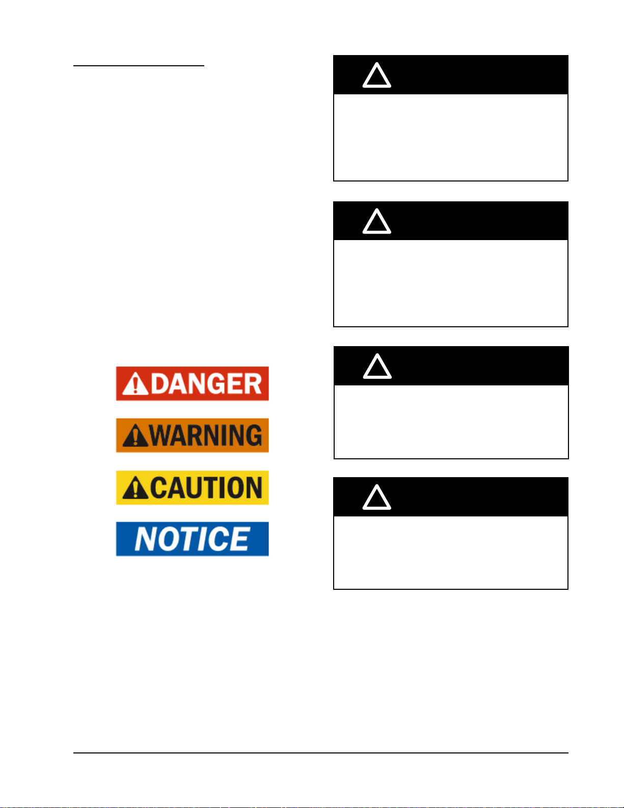
ANSI Z535.5 Definitions:
DANGER: Indicate[s] a hazardous situation which, if
not avoided, will result in death or serious injury. The
signal word “DANGER” is to be limited to the most
extreme situations. DANGER [signs] should not be used
for property damage hazards unless personal injury risk
appropriate to these levels is also involved.
WARNING: Indicate[s] a hazardous situation which,
if not avoided, could result in death or serious injury.
WARNING [signs] should not be used for property
damage hazards unless personal injury risk appropriate
to this level is also involved.
CAUTION: Indicate[s] a hazardous situation which, if
not avoided, could result in minor or moderate injury.
CAUTION [signs] without a safety alert symbol may be
used to alert against unsafe practices that can result in
property damage only.
NOTICE: [this header is] preferred to address practices
not related to personal injury. The safety alert symbol
shall not be used with this signal word. As an
alternative to “NOTICE” the word “CAUTION” without
the safety alert symbol may be used to indicate a
message not related to personal injury.
!
WARNING
Electrical shock hazard.
Have a properly trained individual perform
these tasks.
Failure to do so could result in electric shock
or death.
!
WARNING
Fire hazard.
Maintain minimum 1/4" clearance between the
supply ange and combustible materials.
Failure to do so could result in re causing
damage, injury or death.
!
WARNING
Heavy item hazard.
Use more than one person to handle unit.
Failure to do so could result in unit damage or
serious injury.
!
CAUTION
Cut hazard.
Wear gloves to avoid contact with sharp
edges.
Failure to do so could result in personal injury.
Manual 2100-695
Page 5 of 54
Page 6
USING THE TEC-EYE
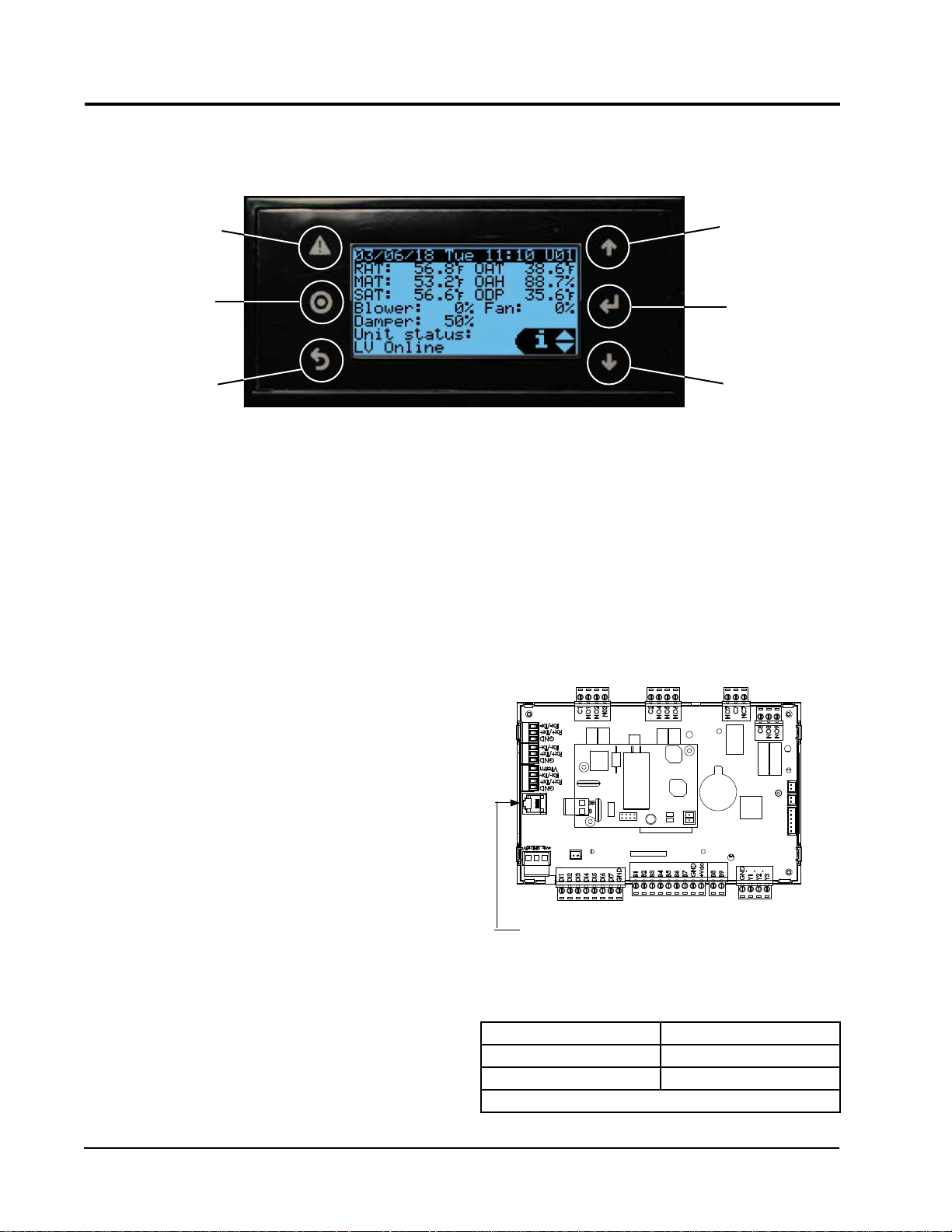
TEC-EYE (Bard P/N 8301-059) Display and Interface (Status Screen Shown)
TM
FIGURE 1
ALARM KEY
MENU KEY
ESCAPE KEY
ALARM KEY
Allows viewing of active alarms
Silences audible alarms
Resets active alarms
MENU KEY
Allows entry to Main Menu
ESCAPE KEY
Returns to previous menu level
Cancels a changed entry
TEC-EYE Hand-Held Diagnostic Tool
The TEC-EYE service tool is used to communicate
with the FUSION-TEC unit logic board. By connecting
directly to the logic board inside the unit control
panel, it is possible to perform diagnostics on the unit,
adjust certain settings and verify unit and economizer
operation through a run test procedure. The TEC-EYE
service tool is required for unit setup and operation. The
TEC-EYE is supplied with the LC6000 controller but
can also be ordered separately (Bard P/N 8301-059).
The menu driven interface provides users the ability
to scroll through two menu levels: Quick Menu and
Main Menu. The menus permit the user to easily view,
control and configure the unit.
The controller is completely programmed at the factory;
the default setpoints and their ranges are easily viewed
and adjusted from the TEC-EYE display. The program
and operating parameters are permanently stored on
FLASH-MEMORY in case of power failure.
The TEC-EYE connects to the wall-mount unit control
board via an RJ11 modular phone connector as shown
in Figure 2.
When not being used, the TEC-EYE hand-held
diagnostic tool should be stored inside or near the
LC6000 controller. Do not let the TEC-EYE leave the
shelter site.
UP KEY
ENTER KEY
DOWN KEY
UP KEY
Steps to next screen in the display menu
Changes (increases) the value of a modifiable field
ENTER KEY
Accepts current value of a modifiable field
Advances cursor
DOWN KEY
Steps back to previous screen in the display menu
Changes (decreases) the value of a modifiable field
FIGURE 2
TEC-EYE Connection to Unit Control
Modular Phone Connector for
TEC-EYE Hand-Held Diagnostic Tool
TABLE 1
LC6000/TEC-EYE Passwords (Defaults)
User 2000
Technician 1313
Engineer 9254
Use UP or DOWN keys and ENTER key to enter password
Manual 2100-695
Page 6 of 54
Page 7
TEC-EYE Screen Structure and Password Level
Quick Menu
Setpoints (Orphan Mode Temperature Control)
Information
Alarm Log
Main Menu
System Config: A1-A10 User (2000)
Adv Sys Config: B1-B8 Technician (1313)
I-O Config: C1-C15 Technician (1313)
On/Off: User (2000)
Alarm Logs: User (2000)
Settings
Date/Time: Technician (1313)
Language: User (2000)
Import/Export
Unit Parameters: Engineer (9254)
Alarm Log Export: User (2000)
7 Day Log Export: User (2000)
Initialization
Alarm Management: User (2000)
System Default: Engineer (9254)
Change Passwords
Logout
In addition to the menu structure above, there are also
Status and Alarm screens.
TEC-EYE Acronyms
MAT – Mixed air temperature (calculated value)
RAT – Return air temperature
SAT – Supply air temperature
OAT – Outdoor air temperature
OAH – Outdoor air humidity
ODP – Outdoor dew point (calculated value)
Blower – Indoor blower speed
Fan – Outdoor fan speed
Damper – Free cooling damper position
FC – Free cooling status
CL1 – Compressor stage 1 status
CL2 – Compressor stage 2 status
H1 – Heater stage 1 status
H2 – Heater stage 2 status
ST – Number of start requests in last hour
NOTE: Digital refers to On/Off whereas analog is a
variable input.
Main Status Screen
The Main Status Screen is the default start-up screen
and also the return screen after 5 minutes of no
activity. The screen can be accessed at any time by
pressing the ESCAPE key repeatedly.
The wall-mount unit address is displayed in the upper
right corner on the main Main Status Screen (see
Figure 1). The Main Status Screen also shows the
current date, time, return air temperature (RAT), mixed
air temperature (MAT), supply air temperature (SAT),
outdoor air temperature (OAT), outdoor air humidity
(OAH) and outdoor dew point (ODP) conditions. Blower
speed, condenser fan speed, damper position and unit
status are also displayed. See Table 2 for wall-mount
unit status messages.
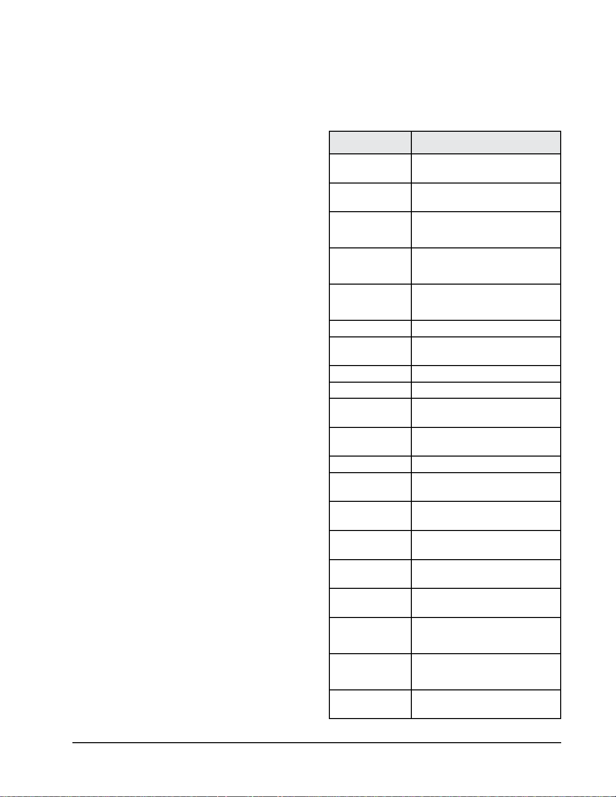
TABLE 2
Unit Status Messages
Message Description
Waiting...
Orphan Mode
LC Online
Cont. Blower
Power Loss
Free Cooling Unit is actively economizing.
Optimized Cool
Cooling Unit is actively mechanical cooling.
Heating Unit is actively heating.
Passive Dehum
Active Dehum
Self Test Unit is performing a self test.
Off by Alarm
Off by DI
Off by LC
Off by Keyboard
Override Active
Emergency Vent
Emergency Cool
Emergency Off
PLC is on and has not started running
the application yet.
Unit is on and in orphan mode with
no calls for heating or cooling.
Unit is on and communicating with
the LC6000 with no heating or
cooling calls.
Unit is operating with continuous
blower when no heating or cooling
calls are present.
Unit has experienced a loss of main
utility power. Alarm only available
with inverter units.
Unit is mechanical cooling while
actively economizing.
Unit is taking measures to decrease
humidity without using extra energy.
Unit is taking active measures to
decrease humidity.
Unit has major fault preventing
operation.
Unit is disabled by the local unit
disable/smoke input.
Unit has been turned off by the
supervisory controller.
Unit has been turned off by the local
user.
There is an active override on the
system.
Unit is in Emergency Ventilation.
LC6000 has an active hydrogen
alarm.
Unit is in Emergency Cooling. Indoor
temperatures have exceeded high
temp alarms.
Unit is in Emergency Off. LC6000
has an active smoke alarm.
Manual 2100-695
Page 7 of 54
Page 8
The Quick Menu is accessible from the
Screen
. Setpoints, Information and Alarm Log are
available through the Quick Menu. Pressing the UP
or DOWN keys while on the
change the Quick Menu icon displayed (see Figure
3). Press the ENTER key when the desired icon is
displayed.
Main Status Screen
Main Status
will
FIGURE 3
Quick Menu Icons
Alarm Log Information
NOTE: Screenshots shown in this manual reflect
default settings (when applicable).
Quick Menu
Setpoints
From this screen, the local unit heating and cooling
setpoints, used for orphan mode operation only, can be
changed.
Once the supervisory controller (LC6000) is connected,
cooling and heating setpoints will be communicated
and local cooling and heating setpoints will be replaced
with the communicated cooling and heating setpoints.
If at any time the wall-mount unit(s) loses
communication with the LC6000 controller, the wallmount unit(s) will go into orphan mode and operate
using the last communicated setpoints.
To verify or change the wall-mount unit cooling and
heating setpoints in orphan mode:
1. Connect the TEC-EYE diagnostic tool to the control
board located in the unit.
2. From the Status screen, press UP or DOWN key
until Quick Menu displays Setpoints icon. Press
ENTER key.
3. Press ENTER key to scroll to the selected choice
(see Figure 4).
Setpoints
FIGURE 4
Cool and Heat Setpoints
4. Press UP or DOWN key on desired value until value
displays correctly.
5. Press ENTER key to save and scroll to next
parameter.
6. Press ESCAPE key until Main Menu screen is
displayed.
Information
The information screens are used as a quick reference
to show unit operational information such as staging,
A/C circuit measurements, last 24 hour run times and
software version.
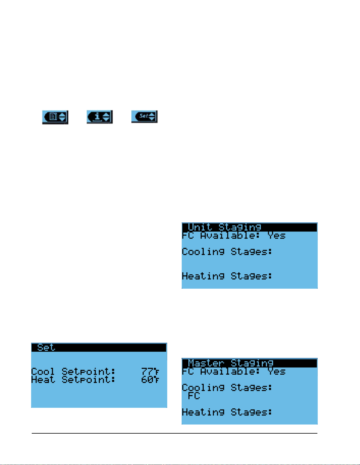
Staging Information
Staging information is used to show if free cooling
is available or if any unit operation should be taking
place. The look of the staging display depends on if the
unit is communicating with a supervisory controller or
operating in orphan mode.
Orphan Mode Staging
If the unit is operating in orphan mode, the title will
display as Unit Staging (see Figure 5). This signifies
that the local unit has control of the unit heating and
cooling stages.
FIGURE 5
Orphan Mode Staging
Master Staging
If the unit is communicating with a supervisory
controller, the title will display as Master Staging (see
Figure 6). This signifies that the supervisory controller
has control of the unit heating and cooling stages.
FIGURE 6
Master Staging
Manual 2100-695
Page 8 of 54
Page 9
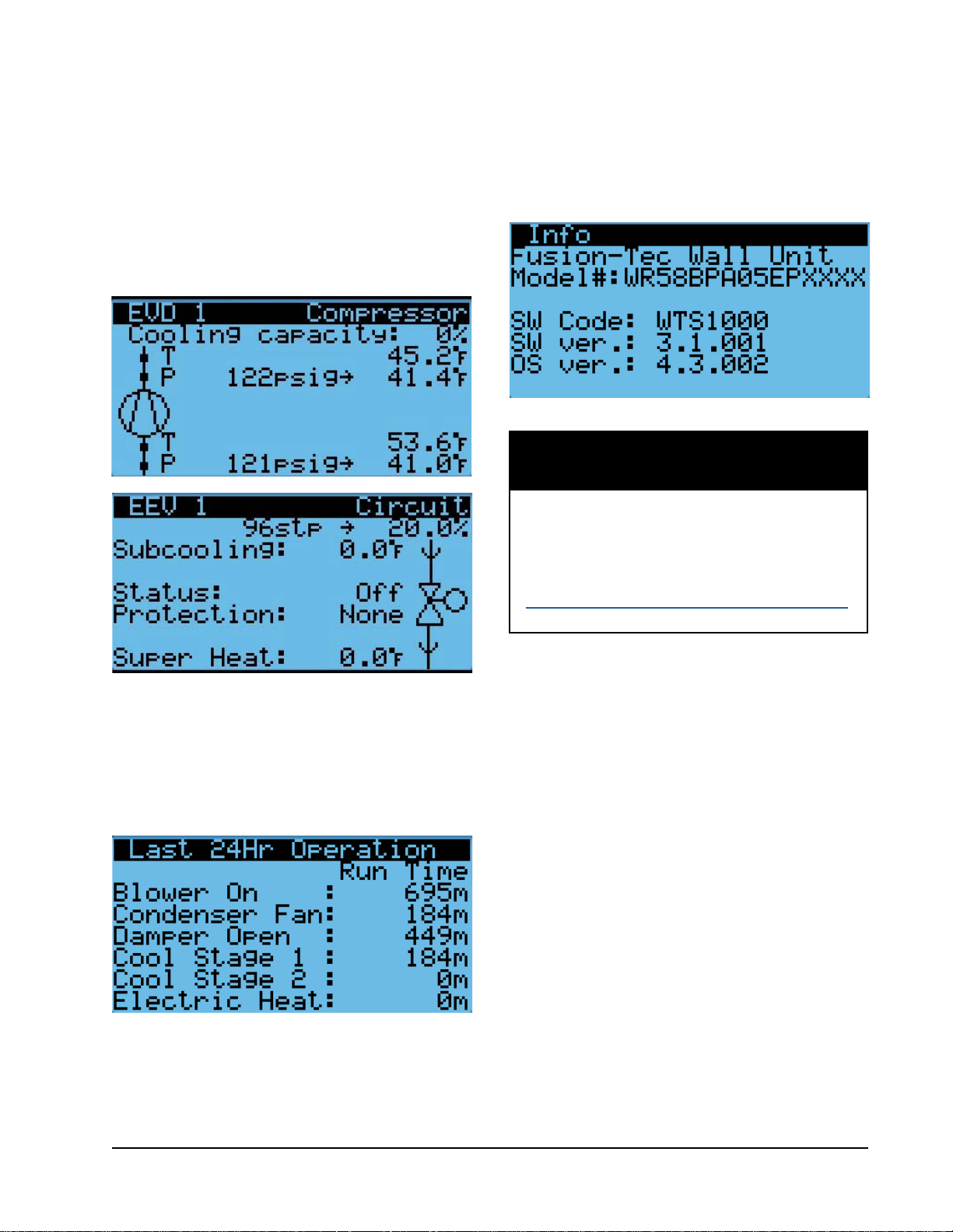
A/C Circuit Measurements
A/C Circuit Information can be found in two screens
within the information menu (see Figure 7). The
information and measurements provided are liquid line
temperature, liquid line pressure, condensing saturated
temperature, suction line temperature, suction line
pressures, suction saturated temperature, super heat,
sub-cooling and electronic expansion valve position.
FIGURE 7
A/C Circuit Measurements
Software Version
The Software Version screen displays the model
number of the unit as well as all software version
information for the PLC (see Figure 9).
FIGURE 9
Software Version
NOTICE
It is important to check the software version
during installation to ensure that the latest
version has been installed. Current software
versions, change log and installation
instructions are available on the Bard website at
http://www.bardhvac.com/software-download/
Last 24 Hour Operation
Last 24 Hour Operation information tracks the runtimes
(Time) of different components or operations in the last
24 hour period (see Figure 8).
FIGURE 8
Last 24 Hour Operation
Alarm Log
The alarm log screens show a log of each alarm. There
will be a log for when alarm occurred and if the alarm
auto clears, it will show when the alarm cleared.
Manual 2100-695
Page 9 of 54
Page 10
Addressing Wall-Mount Units
Each unit must have a unique address for the system
to operate correctly with th LC controller (Ex: 1, 2, 3,
...14 depending on the number of units). The wallmount unit address is displayed in the upper right
corner on the Status screen on the TEC-EYE display
(see Figure 1 on page 6).
To change the unit address:
1. Press MENU key to access the Main Menu screen.
2. Press UP or DOWN keys and ENTER key to enter
USER password 2000.
3. Press UP or DOWN keys to scroll to Sys Config;
press ENTER key.
4. Press ENTER key to scroll to Unit Address (see
Figure 10).
5. Press UP or DOWN keys to change the address to a
value between 1 and 14.
7. Press ENTER key to save.
See page 13 for information on changing unit zone.
FIGURE 10
Changing Unit Address
FIGURE 11
Executing Run Test
7. Press UP or DOWN key to scroll between Run
Test Summary, Motors & Sensors and A/C Circuit
screens.
NOTE:
The Run Test Summary screen (Figure 12) contains
a readout of the test that is currently taking place,
and the Task the technician should be completing to
verify operation.
If the Run Test screens have been exited out
of, they can be returned to by navigating to
Run Test A10 as provided in the instructions
above, pressing ENTER key to scroll to Return
to Screens, pressing UP or DOWN key to
change value to YES and pressing ENTER key.
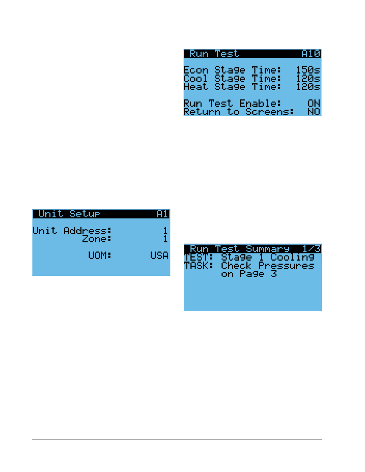
Executing a Run Test
This unit has the ability to perform a run test that will
operate all available unit functions in order to quickly
determine unit operation. Some unit parameters are
adjustable.
To execute a run test:
1. Press MENU key to access the Main Menu screen.
2. Press UP or DOWN keys and ENTER key to enter
TECHNICIAN password 1313.
3. Press UP or DOWN keys to scroll to Sys Config;
press ENTER key.
4. Press UP or DOWN keys to scroll to Run Test A10
screen.
5. Press ENTER key to scroll to Run Test Enable
parameter (see Figure 11).
6. Press UP or DOWN key to change value to ON. The
run test will begin and the screen will change to
Run Test Summary.
FIGURE 12
Run Test Summary
The Motors & Sensors screen (Figure 13) displays
output and estimated positional values for unit motors
and actuators, and also temperature and humidity
sensor values.
Manual 2100-695
Page 10 of 54
Page 11
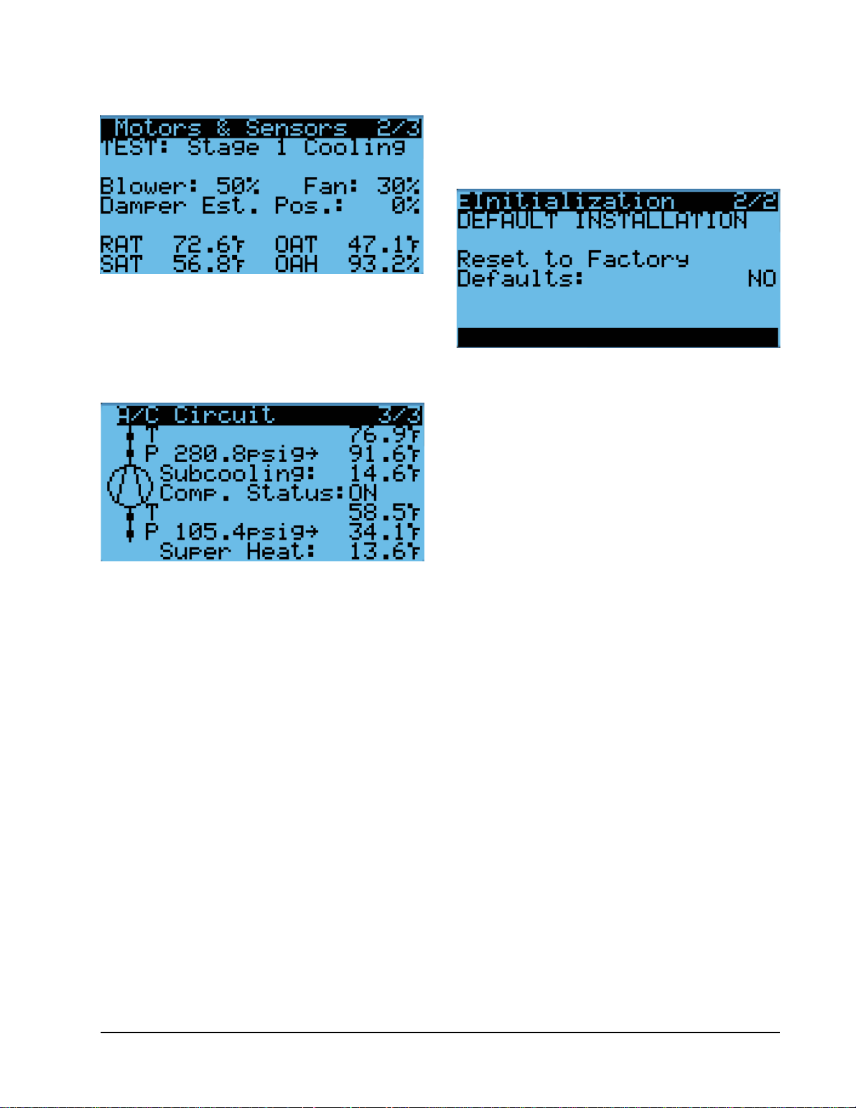
FIGURE 13
Run Test: Motors & Sensors
The A/C Circuit screen (Figure 14) displays all unit
inputs, outputs and calculations associated with the
A/C circuit operation.
FIGURE 14
Run Test: A/C Circuit
7. Press UP or DOWN key to change value to YES;
press ENTER key.
8. System will restart with default values.
FIGURE 15
Restoring Factory Default Settings
Run Test Parameter Descriptions
Econ Stage Time: Amount of time (in seconds)
allowed for damper blade movement in each
direction.
Cool Stage Time: Amount of time (in seconds) allowed
for each stage of cooling.
Heat Stage Time: Amount of time (in seconds)
allowed for heating stage.
Reset to Factory Defaults
To reset to factory default settings:
1. Press MENU key to go to the Main Menu screen.
2. Use UP or DOWN keys and ENTER key to enter
ENGINEER password 9254.
3. Press UP or DOWN keys to scroll to Settings; press
ENTER key.
4. Press UP or DOWN keys to scroll to Initialization;
press ENTER key.
5. Press UP or DOWN keys to scroll to the Default
Installation screen.
6. Press ENTER key to scroll to Reset to Factory
Defaults (see Figure 15).
Manual 2100-695
Page 11 of 54
Page 12
OPERATION
NOTE: Screenshots shown in this manual reflect
default settings (when applicable).
Unit On/Off
The wall-mount unit can be turned on and off from
the TEC-EYE. Turning the unit off with the following
instructions will disable all unit operation.
To turn the unit on or off:
1. Press MENU key to go to the Main Menu screen.
2. Press UP or DOWN keys and ENTER key to enter
USER password 2000.
3. Press UP or DOWN keys to scroll to On/Off; press
ENTER key.
4. Press UP or DOWN keys to change value from On
to Off or from Off to On.
5. Press ESCAPE key several times to return to Main
Menu screen.
The wall-mount unit may also be turned off by certain
alarms. Below is a list of conditions that will disable
unit operation to prevent damage to unit or property:
• System Off (set from LC6000)
• Emergency Off (set from LC6000)
• Unit Disable Input
• Invalid Model Number Size
• Return Air Sensor Failure Alarm in Orphan Mode
• Damper Failed to Close Alarm
• No Airflow Alarm (will cycle unit to attempt blower
restart)
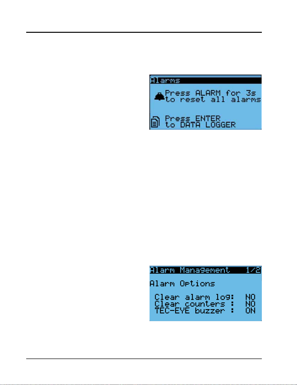
the screen at the end of the alarm list (shown in Figure
16) and press and hold the ALARM key for 3 seconds.
FIGURE 16
Clearing All Alarms
Clearing Alarm Logs and Counters
To clear the alarm log and alarm counters:
1. Press MENU key to go to the Main Menu screen.
2. Use UP or DOWN keys and ENTER key to enter
USER password 2000.
3. Press UP or DOWN keys to scroll to Settings; press
ENTER key.
4. Press UP or DOWN keys to scroll to Initialization.
(Alarm Management 1/2 screen will be displayed.)
5. Press ENTER key to scroll to Clear Alarm Log (see
Figure 17).
6. Press UP or DOWN key to change value to YES;
press ENTER key.
7. Press ENTER key to scroll to Clear Counters.
8. Press UP or DOWN key to value to YES; press
ENTER key.
• Power Loss Input Active on Non-Inverter Model
Number
Alarm Adjustment
Acknowledging Alarms
Alarm conditions activate a red LED indicator that
backlights the ALARM function key. As an option, an
alarm condition may also be enunciated by an audible
alarm signal. An alarm is acknowledged by pressing the
ALARM key. This calls up alarm display screen(s) that
provide a text message detailing the alarm condition(s).
Clearing Alarms
Alarms can only be cleared after the alarm condition
has been corrected. To clear a single alarm, press and
hold the ALARM key for 3 seconds while viewing a
specific alarm screen. To clear all alarms, navigate to
Manual 2100-695
Page 12 of 54
FIGURE 17
Clearing Alarm Logs and Counters
Exporting Alarm Logs
See latest version of Supplemental Instructions manual
7960-815 for information on exporting alarm logs.
Page 13
Exporting 7 Day Logs
See latest version of Supplemental Instructions manual
7960-816 for information on exporting 7 day I/O logs.
Orphan Mode
FUSION-TEC WR Series wall-mount units have the
capability to run without the LC6000 controller
attached—this feature is called orphan mode. This
keeps the shelter between 60°F and 77°F (factory
default settings) by the use of the factory-installed
return air sensor in each wall-mount unit. In orphan
mode, no auxiliary temperature measurement devices
are required for operation. The wall-mount unit
automatically uses a continuous blower setting to
circulate room air into the return air inlet and uses
the return air temperature sensor to control room
temperature.
To change default setpoints, refer to Setpoints on page 8.
During installation, the ability to run in orphan mode
allows deactivation of one of the existing, older wallmount units, while keeping the shelter cool with the
other unit still operating. Once the first of the Bard
wall-mount units is installed and powered on, it will
operate in orphan mode—keeping the climate inside
the shelter stable and the installers comfortable while
the remainder of the older equipment is removed and
the remaining Bard wall-mount units and LC6000
controller are installed.
Additionally, should any or all of the FUSION-TEC WR
Series wall-mount units lose communication with the
LC6000 controller (such as during maintenance), they
will continue to serve the shelter’s needs until a repair
can be made.
Zone
When paired with a supervisory controller that uses
zones to control groups of wall units, this unit uses the
zone setting to relay to the supervisory controller what
zone it is set to operate in.
To change the zone:
1. Press MENU key to access the Main Menu screen.
2. Press UP or DOWN keys and ENTER key to enter
TECHNICIAN password 1313.
3. Press UP or DOWN keys to scroll to Sys Config;
press ENTER key.
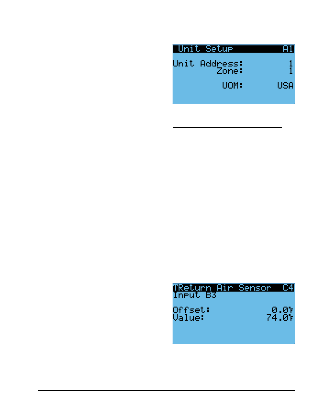
4. Press UP or DOWN keys to scroll to Unit Setup A1
screen.
5. Press ENTER key to scroll to Zone (see Figure 18).
6. Press UP or DOWN keys to change to the desired
value.
7. Press ENTER key to save value.
FIGURE 18
Changing Zone
Temperature/Humidity Control
Temperature/Humidity Control Components
Return Air Temperature Sensor
The unit is equipped with a return air temperature
sensor to monitor the space temperature when the unit
is in orphan mode. The return air sensor is located
in the upper part of the return opening in such a way
that it is exposed to the entering airstream. An alarm
signal will be sent to the LC controller if the return air
temperature sensor is disconnected. The temperature is
measured with a 10k ohm NTC thermistor.
This sensor can be verified and adjusted by:
1. Press MENU key to go to the Main Menu screen.
2. Press UP or DOWN keys and ENTER key to enter
TECHNICIAN password 1313.
3. Press UP or DOWN keys to scroll to I/O Config;
press ENTER key.
4. Press UP or DOWN keys to scroll to Return Air
Sensor C4.
5. Verify the measurement displayed on screen is
accurate (see Figure 19).
FIGURE 19
Adjusting Return Air Sensor
6. If the measurement needs to be adjusted, apply an
offset value by pressing ENTER to scroll to Offset.
7. Press UP or DOWN keys to adjust the offset.
Manual 2100-695
Page 13 of 54
Page 14

8. The update will not take effect until the cursor is
moved out of the Offset parameter.
9. Once adjusted, press the ESCAPE key several
times to return to Main Menu screen.
Return Air Temperature Alarm
When the return air temperature sensor value is out of
range (-41.0 to 303.0°F), the controller will generate
a sensor failure alarm to indicate the sensor is not
working properly.
This alarm is fixed and cannot be adjusted.
Temperature/Humidity Control Operation
When the unit is connected to the LC controller, it
will receive all of its heating, cooling and ventilation
commands from the controller. When the unit is in
orphan mode, it will heat, cool and ventilate based on
the return air temperature measurement. The return air
temperature will be compared to the cooling setpoint.
Based on differentials above and below the setpoint,
the available cooling and heating stages will be utilized.
To change or view the unit setpoint:
1. From the Status screen, press UP or DOWN key
until Quick Menu displays Setpoints icon ( ).
Press ENTER key.
2. Press ENTER key to scroll to Cool Setpoint or Heat
Setpoint (see Figure 4 on page 8).
3. Press UP or DOWN keys to change the value to
desired heating and/or cooling setpoint.
Cooling Sequence – Economizer Available
NOTE: This description is based on the example shown
in Figure 20 and Figure 23 (page 16).
If the return air temperature is higher than 79°F
(Setpoint of 77°F + Stage 1 On Differential of 2°F) and
outdoor conditions are acceptable for economizing, the
unit will enable economizer operation (free cooling).
If the return air temperature is higher than 80°F
(Setpoint of 77°F + Stage 2 On Differential of 3°F),
the unit will enable mechanical cooling stage 1. If the
return air temperature is higher than 81°F (Setpoint
of 77°F + Stage 3 On Differential of 4°F), the unit
will enable mechanical cooling stage 2. Each stage
will then be disabled when the return air temperature
reaches the setpoint plus the stage off differential.
Economizer Operation in Orphan Mode
In orphan mode,there is a chance that the economizer
will not be given ample time to operate before the
heat load requires more cooling. In this case, there is
a delay that can be enabled in order to allow for the
most amount of free cooling to be utilized before the
compressor is staged on.
Free Cooling
Available
Free Cooling
Mechanical
Cooling Stage 1
Mechanical
Cooling Stage 2
Free Cooling
Not Available
Mechanical
Cooling Stage 1
Mechanical
Cooling Stage 2
Not Used
Heat Stage 1
FIGURE 20
Staging
Setpoint
72°F 73°F 74°F 75°F 76°F 77°F 78°F 79°F 80°F 81°F 82°F 83°F
Off
55°F 56°F 57°F 58°F 59°F 60°F 61°F 62°F 63°F 64°F 65°F 66°F
Off
Deadband
Setpoint
Deadband
On
On
NOTE: Deadband refers to a region where one end limit will turn the heating or cooling function on and the opposite end
limit will turn the heating or cooling function off.
Manual 2100-695
Page 14 of 54
Page 15
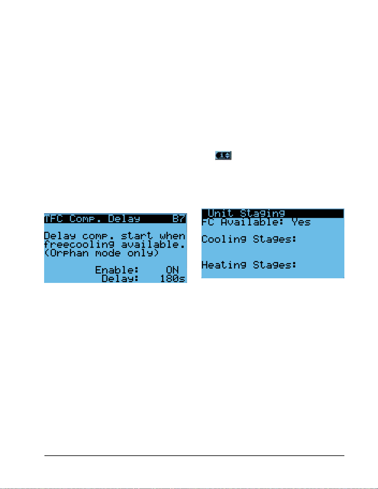
To enable this delay:
1. Press MENU key to go to the Main Menu screen.
2. Press UP or DOWN keys and ENTER key to enter
TECHNICIAN password 1313.
3. Press UP or DOWN keys to scroll to Adv Sys
Config; press ENTER key.
4. Press UP or DOWN keys to scroll to FC Comp.
Delay B7.
5. Press ENTER key to scroll to Enable (see Figure
21).
6. Press UP or DOWN key to change the value.
7. Press ENTER key to save value and move cursor to
Delay.
8. Press UP or DOWN keys to change the time value.
9. Press ENTER key to save value and move cursor to
top of the screen.
10. Press ESCAPE key several times to return to Main
Menu screen.
FIGURE 21
Enabling Free Cooling Delay
when the return air temperature reaches the setpoint
plus the stage off differential.
Staging
The unit will stage the cooling components based on
the cooling demand referenced in the temperature
control. The unit will stage the economizer on first if
the indoor and outdoor conditions are favorable. The
compressor stage 1 will be enabled next as the demand
increases. Finally, the compressor stage 2 will be
enabled as the demand continues to increase.
The unit is only equipped with one stage of heat and
will turn on based on the heating demand.
To view unit stages:
1. From the Status screen, press UP or DOWN key
until Quick Menu displays Unit Information icon
( ). Press ENTER key.
2. The cooling and heating demand are visible on
this screen. The unit stages will display here when
active as FC, CL1, CL2 or H1 (see Figure 22).
FIGURE 22
Viewing Unit Stages
Cooling Sequence – Economizer Not Available
NOTE: This description is based on the example
shown in Figure 20 and Figure 23.
If the return air temperature is higher than 79°F
(Setpoint of 77°F + Stage 1 On Differential of 2°F),
the unit will enable mechanical cooling stage 1. If the
return air temperature is higher than 80°F (Setpoint
of 77°F + Stage 2 On Differential of 3°F), the unit
will enable mechanical cooling stage 2. Each stage
will then be disabled when the return air temperature
reaches the setpoint plus the stage off differential.
Heating Sequence
NOTE: This description is based on the example
shown in Figure 20 and Figure 23.
If the return air temperature is below 58°F (Setpoint
of 60°F + Stage 1 On Differential of -2°F), the unit
will enable electric heat stage 1. If the return air
temperature is below 57°F (Setpoint of 60°F + Stage
2 On Differential), the unit will enable electric heat
stage 2 (if available). Each stage will then be disabled
Adjusting Cooling Staging
This unit uses staging differentials to control cooling
operation. The on differential for a stage references
the number of degrees above the setpoint at which
the stage turns on. The off differential for a stage
references the number of degrees below the setpoint at
which the stage turns off.
To adjust cooling stage differentials:
1. Press MENU key to go to the Main Menu screen.
2. Press UP or DOWN keys and ENTER key to enter
TECHNICIAN password 1313.
3. Press UP or DOWN keys to scroll to Adv Sys
Config; press ENTER key.
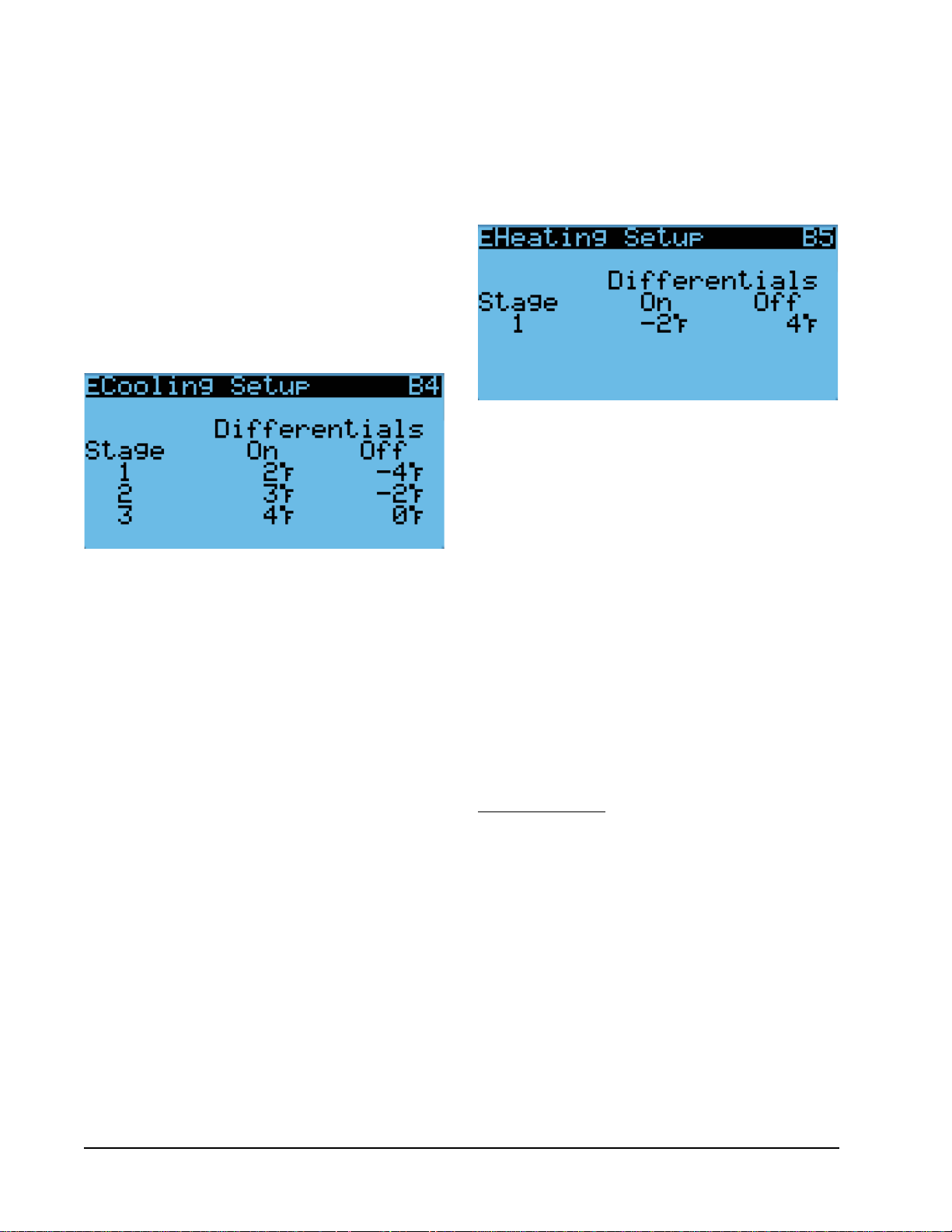
4. Press UP or DOWN keys to scroll to Cooling Setup
B4.
5. Press ENTER key to scroll to Stage 1 On
Differential (see Figure 23 on page 16).
Press UP or DOWN keys to adjust number of
6.
degrees above setpoint to turn cooling operation on.
Manual 2100-695
Page 15 of 54
Page 16
7. Press ENTER key to save value and move cursor to
Stage 1 Off Differential.
8. Press UP or DOWN keys to adjust number of
degrees below setpoint to turn cooling operation
off.
9. Press ENTER key to save value and move cursor to
next stage differential.
10. Repeat steps 6 through 9 for Stage 2 and Stage 3
differentials.
11. Press ESCAPE key several times to return to Main
Menu screen.
FIGURE 23
Adjusting Cooling Stage Differentials
Adjusting Heating Staging
This unit uses staging differentials to control heating
operation. The on differential for a stage references
the number of degrees below the setpoint at which
the stage turns on. The off differential for a stage
references the number of degrees above the setpoint at
which the stage turns off.
To adjust heating stage differentials:
1. Press MENU key to go to the Main Menu screen.
2. Press UP or DOWN keys and ENTER key to enter
TECHNICIAN password 1313.
3. Press UP or DOWN keys to scroll to Adv Sys
Config; press ENTER key.
4. Press UP or DOWN keys to scroll to Heating Setup
B5.
5. Press ENTER key to scroll to Stage 1 On
Differential (see Figure 24).
6. Press UP or DOWN keys to adjust number of
degrees below setpoint to turn heating operation
on.
7. Press ENTER key to save value and move cursor to
Stage 1 Off Differential.
8. Press UP or DOWN keys to adjust number of
degrees above setpoint to turn heating operation
off.
9. Press ENTER key to save value and move cursor to
next stage differential.
10. Repeat steps 6 through 9 for Stage 2 and Stage 3
differentials.
11. Press ESCAPE key several times to return to Main
Menu screen.
FIGURE 24
Adjusting Heating Stage Differentials
Dehumidification
The unit uses a dehumidification sequence that does
not require the electric heat to run at the same time
as the compressor. Instead, the unit will turn on the
compressor to cool down to the heating setpoint.
Once the lower setpoint has been reached, the unit
will heat the space back up to the upper setpoint.
This cycle continues until the humidity level in the
shelter reaches an acceptable level. At this point,
the unit will revert back to normal operation. The
economizer will also be disabled while the unit is in the
dehumidification mode.
NOTE: This feature is dependent upon the LC6000
indoor humidity sensors and a command
from the LC to enter dehumidification mode.
See the latest revision of LC6000 Service
Instructions 2100-669 for adjustment of the
dehumidification setpoint and differentials.
Electronic Expansion Valve (EEV)
EEV Components
Electronic Expansion Valve
The electronic expansion valve is a stepper motor that
is controlled with a step output from the controller. The
valve is capable of 480 steps represented by a 0-100%
signal on the controller. The motor drives a needle valve
that regulates the flow of refrigerant.
EEV Instructions for Vacuum, Reclaim, Charge Unit
The electronic expansion valve moves to the 20% open
position when the unit is not actively cooling. The
valve may need to be manually positioned for service or
troubleshooting. The valve can be positioned by using a
menu override.
Manual 2100-695
Page 16 of 54
Page 17
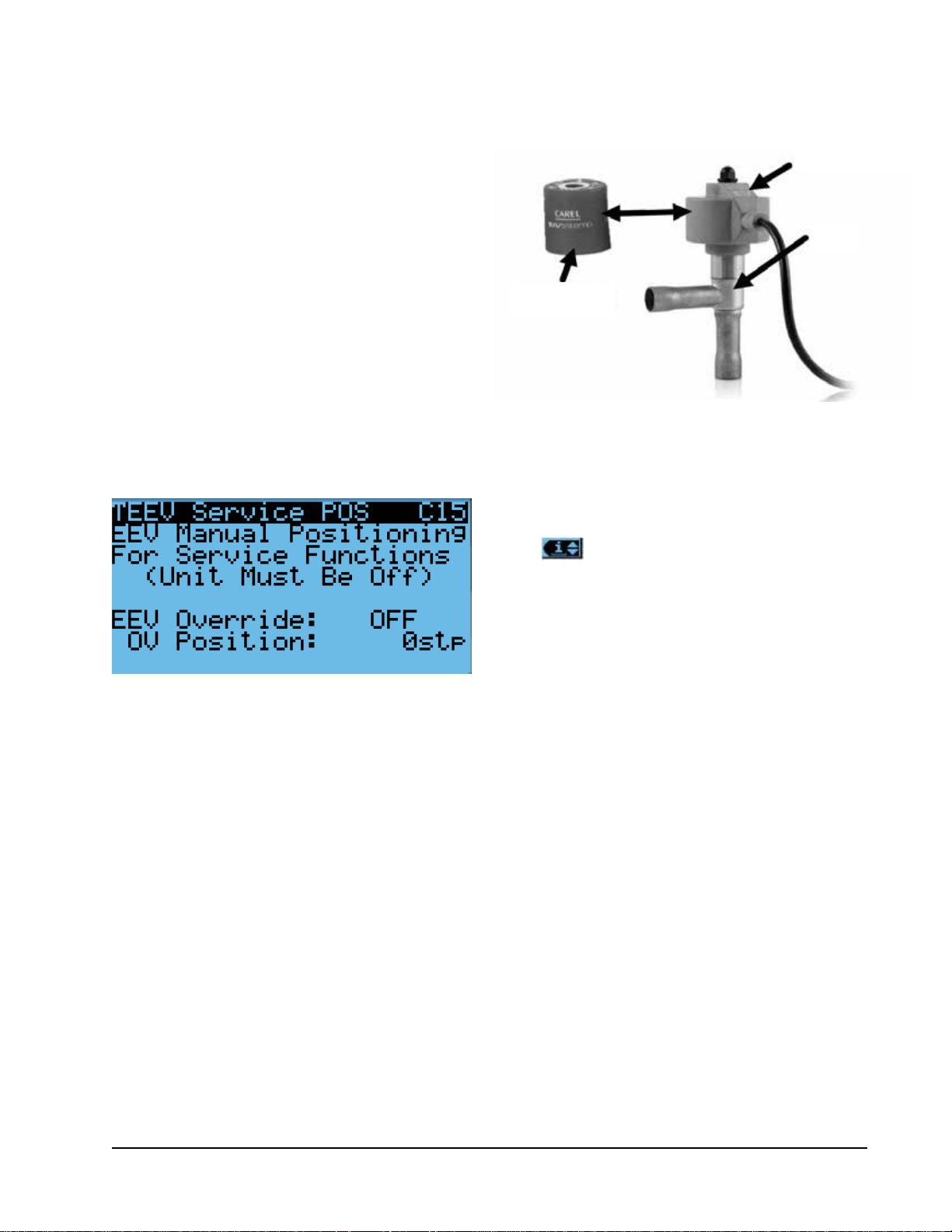
To manually override the valve:
NOTE: The unit must be off to perform this override.
1. Press MENU key to go to the Main Menu screen.
2. Press UP or DOWN keys and ENTER key to enter
TECHNICIAN password 1313.
3. Press UP or DOWN keys to scroll to I/O Config;
press ENTER key.
4. Press UP or DOWN keys to scroll to EEV Service
C15.
Press ENTER key to scroll to Enable (see Figure 25).
5.
6. Press UP or DOWN key to change Disable to
Enable.
7. Press ENTER key to scroll to Position.
8. Press UP or DOWN keys to adjust to the desired
value.
9. Press ENTER key to save.
FIGURE 25
Overriding EEV Output
The valve can also be opened or closed using the EEV
service tool (Bard Part # 2151-021). This magnetic EEV
service tool (shown in Figure 26) is used to manually
open the EEV. To do this, remove the EEV stator coil (red
color with retaining nut on top), slide the magnetic tool
over the shaft where the stator was removed and turn in
a clockwise direction to open the valve to the full open
position (directional arrows are provided on the tool).
Opening the valve to the full open position will aid in the
refrigerant reclamation and evacuation processes.
With the stator removed, the resistance should be 40
ohms +/- 10%. There are two sets of three wires that
will have this resistance.
Reapply the EEV stator coil and retaining nut. Upon
powering the unit back up, the control board will
automatically drive the EEV back to the fully shut
position, and then back to the 20% open position
prior to starting the compressor back up. Once
the compressor starts, the control board will again
modulate the EEV position to control the system
superheat.
FIGURE 26
Electronic Expansion Valve (EEV) and Service Tool
EEV Stator
Coil
EEV
EEV Service
Tool
System Pressures
To view system pressure and temperatures during this
process:
1. From the Status screen, press UP or DOWN key
until Quick Menu displays Information icon
( ). Press ENTER key.
2. Press UP or DOWN keys to scroll to EEV 1 Circuit
and EVD 1 Compressor screens (see Figure 7 on
page 9).
3. Reference the Pressures and Temperatures on EVD
1 Compressor and the Superheat and Subcooling
on EEV 1 Circuit.
Suction Pressure Transducer
The unit has a pressure transducer installed on the
suction line between the evaporator coil and compressor.
The transducer is used for system monitoring of suction
system pressures. The sensor is used with the suction
temperature sensor to provide a real time superheat
calculation that determines the EEV position.
This sensor can be verified and adjusted by:
1. Press MENU key to go to the Main Menu screen.
2. Press UP or DOWN keys and ENTER key to enter
TECHNICIAN password 1313.
3. Press UP or DOWN keys to scroll to I/O Config;
press ENTER key.
4. Press UP or DOWN keys to scroll to Liquid Pr
Sensor C9.
5. Verify the measurement displayed on screen is
accurate (see Figure 27 on page 18).
6. If the measurement needs to be adjusted, apply an
offset value by pressing ENTER to scroll to Offset.
7. Press UP or DOWN keys to adjust the offset.
Manual 2100-695
Page 17 of 54
Page 18

8. The update will not take effect until the cursor is
moved out of the Offset parameter.
9. Once adjusted, press the ESCAPE key several
times to return to Main Menu screen.
FIGURE 27
Adjusting Suction Pressure Transducer Values
Troubleshooting the Suction Pressure Transducer
0-250 psig
-5v Nominal .5 – 4.5v Actual
4v/250 psig = .016 volts per 1 psig
Example: 125 psig x .016 + .5 volts = 2.5 volts
Formula for Tech:
Measured Pressure x .016 + Sensor Offset = Expected
Transducer Signal Voltage (see Figure 28).
The suction temperature sensor measurement can be
verified and adjusted by:
1. Press MENU key to go to the Main Menu screen.
2. Press UP or DOWN keys and ENTER key to enter
TECHNICIAN password 1313.
3. Press UP or DOWN keys to scroll to I/O Config;
press ENTER key.
4. Press UP or DOWN keys to scroll to Suct Temp
Sensor C8.
5. Verify the measurement displayed on screen is
accurate (see Figure 29).
6. If the measurement needs to be adjusted, apply an
offset value by pressing ENTER to scroll to Offset.
7. Press UP or DOWN keys to adjust the offset.
8. The update will not take effect until the cursor is
moved out of the Offset parameter.
FIGURE 29
Adjusting Suction Temperature Sensor Values
FIGURE 28
Voltage to Pressure: Suction Pressure Transducer
Suction Pressure Alarm
When the suction pressure transducer value is out
of range (0-250 PSIG), the controller will generate
a sensor failure alarm to indicate the sensor is not
working properly.
This alarm cannot be adjusted.
Suction Temperature Sensor
The suction temperature sensor is used to calculate
superheat. The EEV uses this value to control the EEV.
The temperature is measured with a 10k ohm NTC
thermistor.
Suction Temperature Alarm
When the suction temperature sensor value is out of
range (-41.0 to 303.0°F), the controller will generate
a sensor failure alarm to indicate the sensor is not
working properly.
This alarm cannot be adjusted.
Evaporator Freeze Condition Alarm
The freeze alarm (evaporator coil freeze protection)
uses the suction temperature sensor to alarm and
manage operation when conditions are favorable for
an evaporator coil freeze condition. Whenever the
compressor is running, the system will constantly
monitor the suction line temperature. If the suction
line temperature falls below the freeze setpoint (32°F
factory default) for a period of time exceeding freeze
alarm delay time (120 seconds factory default), the
system will alarm a freeze condition. Once a freeze
condition is triggered, the system will stop the
compressor operation and increase the blower speed to
80% in order to rapidly warm and thaw the evaporator
coil. After the coil has reached a temperature above the
freeze alarm reset temperature setpoint (55°F factory
default) for a period of time exceeding the freeze alarm
Manual 2100-695
Page 18 of 54
Page 19

reset hold time (5 minutes factory default), normal
operation will continue.
To adjust the freeze setpoint and/or alarm delay time:
1. Press MENU key to go to the Main Menu screen.
2. Press UP or DOWN keys and ENTER key to enter
USER password 2000.
3. Press UP or DOWN keys to scroll to System Config;
press ENTER key.
4. Press UP or DOWN keys to scroll to Alarm Setup
A7.
5. Press ENTER key to scroll to Alarm Setpoint (see
Figure 30).
6. Press UP or DOWN keys to change to the desired
value.
7. Press ENTER key to save the value and move
cursor to Alarm Delay.
8. Press UP or DOWN keys to change to the desired
Alarm Delay value.
9. Press ENTER key to save the value.
FIGURE 30
Adjusting Freeze Setpoint and Alarm Delay
EEV Operation
EEV Superheat Control
The electronic expansion valve (EEV) will modulate to
maintain a specific superheat (see Table 3) while the
compressor is running. When the compressor is not
running, the valve will open to 40% to allow system
equalization.
There are two forms of low superheat protection on
the FUSION-TEC WR Series units. One form will be
active once the superheat value is at or below 5°F. At
this point, the control will aggressively close the valve
to prevent flood back. The second form occurs at low
ambient temperatures. This control will slightly raise
the superheat setpoint based on outdoor temperature to
prevent system instability.
Additional EEV Alarms
Low Superheat Alarm
This alarm will become active when the calculated
superheat goes below 5°F. This alarm will clear itself
when the condition is no longer present.
This alarm cannot be adjusted.
Indoor Airflow
Indoor Airflow Components
Blower
The unit is equipped with a blower that is driven by
an electronically commutated motor (ECM). This
blower is controlled by a 0-10v signal provided from
the controller. This 0-10v signal is converted to a
PWM signal with an adapter. The blowers on both the
WR36BP* and WR58BP* models use a 10" diameter
wheel. The WR36BP* operates between 250-850 rpm
while the WR58BP* operates between 250-1400 rpm.
The blower output can be put into an override mode for
verification or troubleshooting. The override will last for
5 minutes or until the Blower Override parameter is set
to OFF again.
To put the blower into override:
1. Press MENU key to go to the Main Menu screen.
2. Press UP or DOWN keys and ENTER key to enter
TECHNICIAN password 1313.
3. Press UP or DOWN keys to scroll to I/O Config;
press ENTER key.
4. Press UP or DOWN keys to scroll to Blower Output
C12.
5. Press ENTER key to scroll to Blower Override (see
Figure 31).
TABLE 3
Unit Specific Superheat Settings
Unit Size Superheat
WR36 11°F
WR58 12°F
FIGURE 31
Putting Blower Output into Override Mode
Manual 2100-695
Page 19 of 54
Page 20

6. Press UP or DOWN key to change OFF to ON.
7. Press ENTER key to scroll to OV Speed.
8. Press UP or DOWN keys to adjust the speed to the
desired output. See Table 4A or 4B.
9. Press ENTER key to save.
NOTE: If unit is operating at the time the blower
override is being enabled, adjustments must be
made to OV Speed first before switching Blower
Override on.
TABLE 4A
WR36BP* Blower Speeds
Mode
High Sensible
Full Load Cooling
High Sensible
Part Load Cooling
Standard Full
Load Cooling
Standard Part
Load Cooling
Economizer Standard
Economizer High S/T
Heating 63.0 6.3 v 1200
Dehumidification
Mode
Speed
Percentage
94.0 9.4 v 1500
54.0 5.4 v 1100
63.0 6.3 v 1200
43.0 4.3 v 950
90.0
63.0
19.0 1.9 v 470
Controller
Output Volts
9.0 v
6.3 v
CFM
1450
1200
TABLE 4B
WR58BP* Blower Speeds
Mode
High Sensible Full
Load Cooling
High Sensible Part
Load Cooling
Standard Full Load
Cooling
Standard Part Load
Cooling
Economizer Standard
Economizer High S/T
Heating 35.0 3.5 v 1335
Dehumidification
Mode
Speed
Percentage
75.0 7.5 v 2180
50.0 5.0 v 1705
55.0 5.5 v 1830
35.0 3.5 v 1335
45.0
75.0
35.0 3.5 v 1335
Controller
Output Volts
4.5 v
7.5 v
CFM
1600
1950
TABLE 5
Rated Airflow
Nominal Rated CFM
High Low
WR36BP* 1200 950 0.00
WR58BP* 1800 1400 0.10
Nominal Rated ESP
TABLE 6
Indoor Blower Performance
Speed High Low
ESP
(Inch H
WR36BP* 0.00
WR58BP* 0.10
Dry
0)
Coil
2
1260 1200 995 950
1885 1800 1470 1400
Wet
Coil
Dry
Coil
Wet
Coil
TABLE 7
Maximum ESP of Operation
Electric Heat Only
Model Static Pressure*
-A0Z
-A05
-B0Z
-B06
* Unit is rated for free blow non-ducted
operation with SGR-5W Supply Grille
and RGR-5W Return Grille.
.00"
.00"
.00"
.00"
Blower Status Switch
The unit is equipped with a differential pressure airflow
switch to monitor the blower (see Figure 31). If the
blower is turned on and the switch doesn't close to
indicate there is differential pressure between the inlet
and outlet of the blower, an alarm will be generated.
For switch settings, see Figure 32.
Differential airflow status can be viewed by:
1. Press MENU key to go to the Main Menu screen.
2. Press UP or DOWN keys and ENTER key to enter
TECHNICIAN password 1313.
3. Press UP or DOWN keys to scroll to I/O Config;
press ENTER key.
4. Press UP or DOWN keys to scroll to Digital In
Config C1.
5. Reference 7 NoAir row and Val column (see Figure
33).
Manual 2100-695
Page 20 of 54
Page 21

FIGURE 32
Dirty Filter Switch and Blower Status Switch
(Set per Table 8)
(WR36 set @ .012)
(WR58 set @ .020)
Blower Status Alarm
If the blower is commanded on and the fan status
switch (differential pressure) has not indicated the fan
is running within 45 seconds, the system will generate
an alarm.
Disabling the blower status switch in I/O Config
disables this alarm.
This alarm is just a notification and will clear itself
when the conditions are no longer present.
To adjust the air flow alarm delay:
1. Press MENU key to go to the Main Menu screen.
2. Press UP or DOWN keys and ENTER key to enter
USER password 2000.
3. Press UP or DOWN keys to scroll to System Config;
press ENTER key.
4. Press UP or DOWN keys to scroll to Alarm Setup
A8.
5. Press ENTER key to scroll to Air Flow Alarm Del
(see Figure 34).
FIGURE 33
Verifying Differential Airflow Status
Adjusting Air Flow Alarm Delay
FIGURE 34
TABLE 8
Filter Switch Pressure Settings
Unit Filter Blockage % 0% 10% 20% 30% 40% 50% 60% 70%
WR36BP*
(Default) High S/T
WR36BP*
Standard Airflow
WR58BP*
(Default) High S/T
Switch Static Setting 0.12 0.12 0.12 0.20 0.20 0.35 0.35 0.40
Evaporator Airflow % 100% 99.3% 99.4% 98.7% 96.5% 92.1% 91.3% 87.9%
Switch Static Setting 0.12 0.12 0.12 0.12 0.20 0.20 0.20 0.30
Evaporator Airflow % 100% 99.3% 99.4% 98.8% 97.3% 91.5% 89.8% 88.3%
Switch Static Setting 0.40 0.50 0.60 0.70 0.75 0.80 0.90 1.00
Evaporator Airflow % 100% 98.7% 98.1% 97.5% 91.7% 81.3% 79.1% 78.6%
WR58BP*
Standard Airflow
All units tested equipped with MERV 8 filters. Appropriate supply (SG) and return (RG) grilles installed during testing.
Pressure switch adjustment may be necessary due to variations in filter type, installation and room pressure.
Bard recommends filter switch be set at 50% filter blockage or less. Higher settings may significantly hinder unit performance.
Switch Static Setting 0.30 0.35 0.40 0.45 0.50 0.65 0.70 0.90
Evaporator Airflow % 100% 99.8% 99% 98.5% 96.8% 89.9% 84% 82.2%
Manual 2100-695
Page 21 of 54
Page 22

6. Press UP or DOWN keys to change to the desired
value.
7. Press ENTER key to save the value.
Filters
The unit is equipped with two (2) 20" x 30" x 2" MERV
8 filters. The filters slide into position making them easy
to service. The filters can be serviced from the outside
by removing either the right or left filter access panel.
Dirty Filter Switch
These units are equipped with a differential pressure
switch to indicate when the filter(s) needs to be
replaced (see Figure 32). The dirty filter switch
measures the pressure difference across the filter
through silicone tubing routed to the blower and vent
areas of the unit.
The switch circuit consists of a normally open filter
pressure switch. The switch will open when the
pressure differential goes above the setting indicated
on the dial. When the pressure difference returns below
the setting on the dial, the switch will close.
FIGURE 35
Dirty Filter Switch and Filter Indicator Light
Adjustment of dirty filter switch may be necessary to
ensure proper operation. See Table 8 and Figure 35 to
aid in setting the filter switch to operate at different
percentages of filter blockage.
Dirty Filter Alarm
The wall-mount unit is equipped with a differential
pressure switch input to the controller (see Figure 32).
When the switch indicates a dirty filter, the controller
will generate an alarm. Once the condition is no longer
present, the alarm will automatically clear. Additionally,
an indicator light will be turned on with the alarm and
turned off when the alarm clears (see Figure 35).
Disabling the dirty filter switch in I/O Config disables
this alarm.
The threshold of this alarm is adjusted by changing the
settings on the switch (see Table 8).
Filter Indicator Light
These units are equipped with a 24v indicator light
mounted on side of unit that displays the current status
of the filter (see Figure 35). When the light is on, the
ADJUSTMENT
INDICATOR ARROW
ADJUSTMENT
KNOB
TUBE LOCATED IN
AIRSTREAM AFTER FILTER
FILTER
LIGHT
SCREW TO
REMOVE COVER
COVER
Manual 2100-695
Page 22 of 54
TUBE LOCATED IN
AIRSTREAM BEFORE FILTER
MIS-3901
Page 23

filter needs to be replaced. Once the filter(s) has been
changed, the indicator light will turn off.
Indoor Airflow Operation
High Sensible Mode
High sensible mode allows for higher airflow through
the indoor air section. In this mode, air circulation is
increased through the cooled space, but less moisture
is removed from the air circulating through the unit.
NOTE: High sensible enable on the wall-mount unit
will only toggle high sensible mode during
orphan mode operation. When connected to the
LC6000 controller, the high sensible mode will
be overridden by the controller operation.
To change these settings:
1. Press MENU key to go to the Main Menu screen.
2. Press UP or DOWN keys and ENTER key to enter
TECHNICIAN password 1313.
3. Press UP or DOWN keys to scroll to Adv System
Config; press ENTER key.
4. Press UP or DOWN keys to scroll to Blower CFM
Mode B6.
5. Press ENTER key to scroll to High Sensible (see
Figure 36).
6. Press UP or DOWN keys to change ON or OFF
value.
7. Press ENTER key to save.
FIGURE 36
Enabling High Sensible Mode
Additional Indoor Airflow Alarms
Supply Air Temperature Alarm
When the supply air temperature sensor value is out of
range (-41.0 to 303.0°F), the controller will generate
a sensor failure alarm to indicate the sensor is not
working properly.
This alarm is fixed and cannot be adjusted.
Condenser Fan
Condenser Fan Components
Condenser Fan
The unit is equipped with a condenser fan that is driven
by an electronically commutated motor (ECM). This
fan is controlled by a 0-10v signal provided from the
controller. The fan operates between 100-1200 rpm.
To view the output of the condenser fan:
1. Press MENU key to go to the Main Menu screen.
2. Press UP or DOWN keys and ENTER key to enter
TECHNICIAN password 1313.
3. Press UP or DOWN keys to scroll to I/O Config;
press ENTER key.
4. Press UP or DOWN keys to scroll to Cond. Fan
Output C14.
5. Reference Fan Speed parameter for the current
output to the condenser fan (see Figure 37).
FIGURE 37
Verifying Condenser Fan Output
Blower Speed Control
The blower is capable of changing speeds to best match
the requirements of the system depending on which mode
the system is in (see Table 4A or Table 4B on page 20).
The unit will automatically switch to the required
speed for each mode. High sensible mode and
dehumidification mode are both communicated
separately from the LC. For more information on the
high sensible command from LC, please see LC6000
Service Instructions 2100-669.
If required, the condenser fan output can be manually
set for 5 minutes for troubleshooting purposes. The
override will last for 5 minutes or until the Fan Override
parameter is set to OFF again.
To put the condenser fan into override:
1. Press ENTER key to scroll to the Fan Override
parameter (see Figure 37).
2. Press UP or DOWN keys to change the value from
OFF to ON.
3. Press ENTER key to save the value and move
cursor to OV Speed.
Manual 2100-695
Page 23 of 54
Page 24

4. Press UP or DOWN keys to change the value to the
desired override speed.
5. The fan should now run at the selected speed. The
output can be verified by again referencing the Fan
Speed parameter.
NOTE: If unit is operating at the time the fan override
is being enabled, adjustments must be made to
OV Speed first before switching Fan Override on.
Due to design considerations of the condenser section
of the wall-mount unit, placement/clearance of the
motor/fan blade is critical to heat dispersal. Should a
change of motor or fan blade be necessary, see Figure
38 for proper clearance adjustment.
FIGURE 38
Fan Blade Setting
.75" (from the closest point on the fan blade)
7. Press UP or DOWN keys to adjust the offset. The
update will not take effect until the cursor is
moved out of the offset parameter.
8. Once adjusted, press the ESCAPE key several
times to return to Main Menu screen.
FIGURE 39
Adjusting Liquid Pressure Transducer Values
Troubleshooting the Liquid Pressure Transducer
0-650 psig
0-5v
4v/650 psig = .00615 volts per 1 psig
Example: 325 psig x .00615 + .5 v = 2.5 volts
Formula for Tech:
Measured Pressure x .00615 + Sensor Offset =
Expected Transducer Signal Voltage (see Figure 40).
Liquid Line Pressure Transducer
The unit has a pressure transducer installed on the
liquid line between the condenser and electronic
expansion valve (EEV). The transducer is used for
system monitoring of the liquid side system pressures.
This information is used to indicate when outdoor coil
cleaning is necessary based on outdoor conditions and
system pressures. The sensor is also used to adapt
the condenser fan speed for high and low ambient
conditions. The liquid line transducer is also referred to
as the discharge pressure sensor.
The discharge pressure sensor input can be verified and
adjusted by:
1. Press MENU key to go to the Main Menu screen.
2. Press UP or DOWN keys and ENTER key to enter
TECHNICIAN password 1313.
3. Press UP or DOWN keys to scroll to I/O Config;
press ENTER key.
4. Press UP or DOWN keys to scroll to Liquid Pr
Sensor C9.
5. Verify the measurement displayed on screen is
accurate (see Figure 39).
6. If the measurement needs to be adjusted, apply an
offset value by pressing the ENTER key to scroll to
Offset.
FIGURE 40
Voltage to Pressure:
Liquid Pressure Transducer
Liquid Pressure Transducer Alarm
When the liquid line pressure sensor value is out
of range (0-650 PSIG), the controller will generate
a sensor failure alarm to indicate the sensor is not
working properly.
This alarm is fixed and cannot be adjusted.
Liquid Temperature Sensor
The unit is equipped with a liquid line temperature
sensor to monitor the temperature of the liquid
refrigerant leaving the condenser and entering the EEV.
Manual 2100-695
Page 24 of 54
Page 25

The temperature is measured with a 10k ohm NTC
thermistor.
The liquid temperature sensor can be verified and
adjusted by:
1. Press MENU key to go to the Main Menu screen.
2. Press UP or DOWN keys and ENTER key to enter
TECHNICIAN password 1313.
3. Press UP or DOWN keys to scroll to I/O Config;
press ENTER key.
4. Press UP or DOWN keys to scroll to Liquid Temp
Sensor C2.
5. Reference the Value to verify the temperature (see
Figure 41).
FIGURE 41
Adjusting Liquid Temperature Values
6. If an offset needs to be applied, press ENTER key
to scroll to Offset.
7. Press UP or DOWN keys to change the offset to
desired value.
8. Press ENTER key to save.
9. Press ESCAPE key several times to return to Main
Menu screen.
Condenser Fan Operation
Condenser Fan Speed Control
The unit is equipped with a variable speed ECM
(electronically commutated motor) condenser fan which
allows the unit to better control head pressures for
more efficient operation. The fan will speed up or slow
down to attempt to maintain a liquid line pressure.
The pressure setpoint that the fan will control to is
determined by the outdoor air temperature. The unit
will allow the liquid line pressure setpoint to increase
for high ambient scenarios or decrease for low ambient
scenarios. Because the control is dependent on both
the outdoor temperature sensor and the liquid line
pressure sensor, the controller will alter its operation
if a sensor is not enabled or failed. When the outdoor
temperature sensor is not enabled or is considered
failed by the controller, a nominal setpoint of 430
psi is used for fan control. When the liquid pressure
transducer is not enabled or is considered failed by the
controller, a nominal fan speed will be used during a
compressor call. See Figure 42.
The condenser fan requires the compressor to be
running in order to operate.
High Pressure Control
Condenser Fan Speed
When the liquid pressure reaches 550 PSI, the
condenser fan will speed up, moving as much air as
possible in an attempt to reduce system pressures. The
condenser fan will operate at increased speed until the
liquid pressure reaches 450 PSI. At this point, the fan
will return to normal operating speed.
FIGURE 42
Liquid Pressure Control Setpoint
Manual 2100-695
Page 25 of 54
Page 26

Second Stage Drop Out
If the liquid pressure reaches 620 PSI, the second
stage of cooling will be disabled for the remainder
of the current cooling call. This reduces the risk of
tripping the high pressure switch, while still allowing
cooling.
Low Ambient Control
At low ambient outdoor air temperatures, the fan motor
will cycle as a means of controlling the system's head
pressure to protect the system from evaporator coil freeze
conditions. The process for this system is as follows: If
the liquid pressure falls below 275 PSI, the condenser
fan will turn off. The fan will remain off while the
compressor remains running, allowing the head pressure
to build up. Once the liquid pressure reaches 350 PSI,
the fan will then turn back on at the appropriate speed.
At lower ambient outdoor temperatures, this may cycle
regularly as normal operation. In some cases, in higher
wind prone areas, the condenser fan may stay off for
prolonged durations due to low liquid pressures.
Compressor
Compressor Components
Compressor
Three Phase Scroll Compressor Start Up Information
Scroll compressors, like several other types of
compressors, will only compress in one rotational
direction. Direction of rotation is not an issue with
single phase compressors since they will always start
and run in the proper direction.
However, three phase compressors will rotate in either
direction depending upon phasing of the power.
Since there is a 50-50 chance of connecting power
in such a way as to cause rotation in the reverse
direction, verification of proper rotation must be made.
Verification of proper rotation direction is made by
observing that suction pressure drops and discharge
pressure rises when the compressor is energized.
Reverse rotation also results in an elevated sound level
over that with correct rotation, as well as substantially
reduced current draw compared to tabulated values.
Verification of proper rotation must be made at the time
the equipment is put into service. If improper rotation
is corrected at this time, there will be no negative
impact on the durability of the compressor. However,
reverse operation for over 1 hour may have a negative
impact on the bearing due to oil pump out.
NOTE: If compressor is allowed to run in reverse
rotation for an extended period of time, the
compressor’s internal protector will trip.
All three phase compressors are wired identically
internally. As a result, once the correct phasing is
determined for a specific system or installation,
connecting properly phased power leads to the same
Fusite terminal should maintain proper rotation direction.
The direction of rotation of the compressor may be
changed by reversing any two line connections to the
wall-mount unit.
Compressor Control Module (CCM)
Delay-on-Make Timer
Short Cycle Protection/Delay-on-Break
Test Mode
High Pressure Detection
Brownout Protection with Adjustment
The LPC terminals are jumpered in this application.
Instead, the low pressure transducer is used for low
pressure monitoring.
Delay-on-Make Timer
In the event of power loss, a delay-on-make timer is
included to be able to delay startup of the compressor.
This is desired when more than one unit is on a
structure so that all of the units do not start at the
same time which could happen after a power loss or
building shutdown. The delay-on-make time period is
2 minutes plus 10% of the delay-on-break time period.
To ensure that all of the units do not start at the same
time, adjust the delay-on-break timer on each unit to a
slightly different delay time.
Short Cycle Protection/Delay-on-Break
An anti-short cycle timer is included to prevent short
cycling the compressor. This is adjustable from 30
seconds to 5 minutes via the adjustment knob (see Figure
43). Once a compressor call is lost, the time period must
expire before a new call will be initiated.
10% of this time is also considered on the delay-onmake timer (see above).
High Pressure Detection
High pressure switch monitoring allows for a lockout
condition in a situation where the switch is open. If the
high pressure switch opens, the CCM will de-energize
the compressor. If the switch closes, it will then restart
the compressor after the delay-on-break setting has
expired on the device. If the switch trips again during
the same Y call, the compressor will be de-energized.
The ALR terminal will be energized signaling the unit
control board that a high pressure event has occurred
(see Refrigerant High Pressure Alarm on page 28).
Test Mode
By rapidly rotating the potentiometer (POT) clockwise
(see Figure 43), all timing functions will be removed
for testing.
The conditions needed for the unit to enter test mode
are as follows: POT must start at a time less than or
equal to the 40 second mark. The POT must then be
rapidly rotated to a position greater than or equal to
the 280 second mark in less than ¼ second. Normal
operation will resume after power on reset or after the
unit has been in test mode for at least 5 minutes.
Manual 2100-695
Page 26 of 54
Page 27

FIGURE 43
8201-164 Compressor Control Module
High Pressure Switch Compressor Contactor Output
18-30 VAC Input
Y Input from Thermostat
and High Pressure Switch
Troubleshooting Light
Jumper
Brownout Protection with Adjustment
Brownout protection may be necessary if the utility
power or generator power has inadequate power to
prevent the voltage from dropping when the compressor
starts. This is rare but can happen if the generator
is undersized at the site or if the site is in a remote
location far from the main power grid. Under normal
circumstances, allowing the brownout to be ignored for
a time period should not be needed. The 8201-164 is
shipped with all the DIP switches in the 'off' or 'do not
ignore' position (see Figure 43).
If ignoring the brownout is needed because of the
above conditions, three preset timers can be set by DIP
switches in order to delay signaling a power brownout
for a specific length of time after compressor contactor
is energized. This allows the compressor a time period
to start even if the voltage has dropped and allows the
voltage to recover. This delay only happens when the
CC terminal energizes. The delay can be set to 500
milliseconds (A DIP switch), 1000 milliseconds (B DIP
switch) or 1500 milliseconds (C DIP switch); time is
not cumulative—only the longest setting will apply. If
Alarm Output
Common
Delay-on-Break Time
Adjustment Potentiometer
Brownout Ignore Time DIP Switches*
* Turn on only one switch for that specific ignore time setting
the voltage recovers during the brownout time period,
the compressor will start.
If a brownout condition is detected by the 8201-164,
the troubleshooting light will flash blue. The light will
continue to flash until the cooling call is satisfied or
power is removed from the Y terminal. This condition
does not prevent operation, it only indicates that a
brownout condition was present at some point during
the cooling call. If a brownout condition is detected,
CC will be de-energized and will retry after the delayon-make timer is satisfied; this process will continue
until call is satisfied.
If user chooses the 'do not ignore' position when the
site has inadequate utility or generator power, this
could lead to the compressor never starting. The
control will
see the brownout immediately and not start.
A common scenario and one that has been seen in the
field is when a unit or units switches from utility power
to generator power. With slower transfer switches, the
time delay between the utility power and generator power
didn’t cause a problem. The units lost power, shut off
and came back on line normally. With the introduction of
Manual 2100-695
Page 27 of 54
Page 28

almost instantaneous transfer switches, the millisecond
long power glitch can be enough that the compressor will
start to run backwards. In this scenario, the CCM will
catch this and restart the units normally.
High Pressure Safety Switch
All units have a high pressure switch as a safety device.
This device will open when pressure in the system
reaches 650 PSIG. The sensor is directly connected
to the dedicated compressor control module (see High
Pressure Detection on page 26).
Refrigerant High Pressure Alarm
When the wall-mount unit receives a signal from the
compressor control module (CCM) indicating a high
pressure event, the wall-mount unit will generate an
alarm. Upon receiving the alarm, the wall-mount unit
will remove the “Y” call from the CCM, resetting the
status of the CCM. The alarm will stay present on the
wall-mount unit until manually cleared with TEC-EYE
hand-held diagnostic tool.
In addition to the CCM, the discharge pressure
transducer is used to prevent a high pressure event.
When the discharge pressure is above the discharge
pressure alarm setpoint (set 30 PSI below high
pressure switch, which is 650 PSI), the system will
disable stage 2 of mechanical cooling.
Phase Monitor
Used only on three phase equipment, the phase
monitor is a compressor protection device that will
prohibit operation of the compressor if the device senses
a possible reverse-rotation situation due to incorrect
phasing. On a call for compressor (and only compressor),
the device will check incoming phase, check for severe
voltage imbalance and check for proper frequency.
Under nominal conditions, a green LED light will show
on the face of the monitor. If there is improper phasing,
voltage imbalance or frequency deviation, the device will
show a red LED light and prohibit compressor operation.
If a fault condition occurs, reverse two of the supply
leads to the unit. Do not reverse any of the unit factory
wires as damage may occur.
Compressor Operation
The compressor will be enabled when the unit (in
orphan mode) or LC provide a cooling stage 1 call. The
compressor call from the controller has several delays
that may affect the start or stop time of the compressor
in regards to the cooling demand. The compressor has
a minimum on time of 120 seconds to prevent short
cycling the compressor. The compressor also has a
minimum off time of 120 seconds to prevent start
ups before the pressure in the refrigeration system
equalizes. When the second stage is engaged, it also
has a minimum run time of 120 seconds to allow the
system to stabilize before returning to single stage or
shutting down.
These delays can be changed by:
1. Press MENU key to go to the Main Menu screen.
2. Press UP or DOWN keys and ENTER key to enter
TECHNICIAN password 1313.
3. Press UP or DOWN keys to scroll to Adv System
Config; press ENTER key.
4. Press UP or DOWN keys to scroll to Compressor
Config B2.
5. Press ENTER key to scroll to Min On or Min Off
(see Figure 44).
6. Press UP or DOWN keys to change the value.
7. Press ENTER key to save value and move the
cursor to next parameter or top of screen.
8. Press ESCAPE key several times to return to Main
Menu screen.
FIGURE 44
Adjusting Compressor Delays
The address-based delay only applies to the wall-mount
unit when in orphan mode. The controller will delay the
unit compressor based on the value entered on screen
B2 multiplied by the unit address. This is intended to
keep multiple units from starting their compressors
at the same time when there is a quick change in the
load. When connected to the LC, this is taken care of
by LC logic.
Compressor Low Temperature Limit
The unit has the ability to protect the compressor
from refrigerant flood-back in low outdoor temperature
conditions (0°F default). This will be automatically
enabled, unless the economizer is disabled by the
model number. This function can also be enabled/
disabled, and limit temp changed by the user.
To adjust compressor low temp limit:
1. Press MENU key to go to the Main Menu screen.
2. Press UP or DOWN keys and ENTER key to enter
TECHNICIAN password 1313.
3. Press UP or DOWN keys to scroll to Adv System
Config; press ENTER key.
4. Press UP or DOWN keys to scroll to Compressor
Config B3.
Manual 2100-695
Page 28 of 54
Page 29

5. Press ENTER key to scroll to Comp. Limit (see
Figure 45).
6. Press UP or DOWN keys to change ON or OFF
value.
7. Press ENTER key to save value and move the
cursor to Cutoff Temp.
8. Press UP or DOWN keys to adjust temperature.
9. Press ENTER key to save value.
10. Press ESCAPE key several times to return to Main
Menu screen.
FIGURE 45
Adjusting Compressor Low Temp Limit
Additional Compressor Alarms
Refrigerant Low Pressure Alarm
When the suction pressure transducer indicates a
pressure value below the low pressure alarm setpoint of
40 PSI and the compressor has been running for more
than 180 seconds, or the suction pressure is pulled
into a vacuum for more than 20 seconds, the controller
will disable the compressor. NOTE: The second call
will be delayed based on the delay off value mentioned
in the compressor section. The controller will try to
run the refrigeration system two (2) times within
3600 seconds (1 hour) before the alarm will lock the
compressor out. This alarm needs to be manually
cleared before compressor operation will resume.
To adjust the low pressure alarm settings:
1. Press MENU key to go to the Main Menu screen.
2. Press UP or DOWN keys and ENTER key to enter
USER password 2000.
3. Press UP or DOWN keys to scroll to System Config;
press ENTER key.
4. Press UP or DOWN keys to scroll to Alarm Setup
A6.
5. Press ENTER key to scroll to Delay to adjust how
long the compressor waits before turning the
compressor off (see Figure 46).
6. Press UP or DOWN keys to adjust the time delay.
7. Press ENTER key to scroll to Two Count Delay.
8. Press UP or DOWN keys to adjust the delay value.
9. Press ENTER key to save.
10. Press the ESCAPE key several times to return to
Main Menu screen.
FIGURE 46
Adjusting Low Pressure Alarm Settings
Economizer
Economizer Components
Actuator
The actuator rotates up to 90° based on a 2-10v signal
sent to it by the controller. The actuator is rated at
90 in-lb and is spring return when power is lost. This
component is what opens and closes the damper blade.
To verify the output from the controller to the actuator:
1. Press MENU key to go to the Main Menu screen.
2. Press UP or DOWN keys and ENTER key to enter
TECHNICIAN password 1313.
3. Press UP or DOWN keys to scroll to I/O Config;
press ENTER key.
4. Press UP or DOWN keys to scroll to Damper Output
C13.
5. Reference the Damper Position for the current
output to the damper (see Figure 47).
FIGURE 47
Damper Output and Override
6. To override the current position, press ENTER key
to scroll to OV Pos.
7. Press UP or DOWN keys to change the value to the
desired output.
Manual 2100-695
Page 29 of 54
Page 30

8. Press ENTER key to save the value and move
cursor to Damper Override.
9. Press UP or DOWN keys to change the value from
OFF to ON.
10. The Damper Position will update with the new
override value and the damper will travel to that
position.
The override will last for 5 minutes or until the Damper
Override parameter is set to OFF again.
NOTE: If unit is operating at the time the damper
override is being enabled, adjustments must be
made to OV Speed first before switching Damper
Override on.
Dust Sensor
The unit has a dust sensor installed near the outdoor air
inlet. The dust sensor checks for excessive particulates
in the outdoor air, and will close the economizer if
the dust is excessive. The sensor uses a PWM signal
converted to 0-5v output to the controller.
To ensure proper performance, cleaning may be
required. Vacuuming or blowing the dust off the sensor
with forced air is recommended. Avoid inserting any
objects into the sensor.
The dust sensor can be verified by:
1. Press MENU key to go to the Main Menu screen.
2. Press UP or DOWN keys and ENTER key to enter
TECHNICIAN password 1313.
3. Press UP or DOWN keys to scroll to I/O Config;
press ENTER key.
4. Press UP or DOWN keys to scroll to Dust Sensor
C7.
5. Reference the Value for the current sensor reading
(see Figure 48).
FIGURE 48
Dust Sensor
NOTE: The sensor can be disabled if required for
troubleshooting.
9. Press ENTER key to scroll to Enable parameter.
10. Press UP or DOWN keys to change the value from
ON to OFF.
11. Press ENTER key to save.
Dust Sensor Failure Alarm
When the sensor reads a value that is outside of
the acceptable 0 to 100% range, an alarm will be
generated indicating the sensor has failed. This alarm
is just a notification and will not disable any other
features on the controller.
This alarm is fixed and cannot be adjusted.
High Dust Limit Alarm
When dust content in the air is high and is a risk
to prematurely reducing airflow through the filters,
the unit will restrict the use of the economizer. The
controller has adjustable software setpoints (default to
80%) to indicate dust levels are too high and to disable
the economizer operation for 5 minutes (unit default).
This alarm is not communicated to the NOC. Once
the conditions are no longer present, the alarm will
automatically clear.
Disabling the dust sensor in I/O Config disables this
alarm.
To adjust the dust sensor alarm setpoint:
1. Press MENU key to go to the Main Menu screen.
2. Press UP or DOWN keys and ENTER key to enter
USER password 2000.
3. Press UP or DOWN keys to scroll to System Config;
press ENTER key.
4. Press UP or DOWN keys to scroll to Alarm Setup
A9.
5. Press ENTER key to scroll to Setpoint (see Figure
49).
6. Press UP or DOWN keys to change to the desired
value.
7. Press ENTER key to save the value.
6. To apply an offset to the current reading, press
ENTER key to scroll to Offset.
7. Press UP or DOWN keys to adjust the value to the
desired value.
8. Press ENTER key to save the value and move
cursor back to top of screen.
Manual 2100-695
Page 30 of 54
FIGURE 49
Adjusting Dust Sensor Alarm Setpoint
Page 31

NOTE: When the temperature outside is measured
at or below 0°F, the dust sensor alarm will be
disabled to allow economizer operation. This
is done because the compressor is disabled
below 0°F and the system would not have the
capability to cool.
Damper Blade
The system utilizes three damper blades used to bring
in outdoor air and exhaust space air for economizer
operation. The damper blades are made of sheet metal
and are integrated into the equipment.
Minimum Damper Position
This unit has a minimum damper position feature to
vent the space and intake fresh air whenever the blower
is operating. This feature operates separately from free
cooling operation and minimum position should not
be set to a higher position than needed, as it is not
controlled by room or outdoor conditions. This feature
is disabled by default, but is available if needed.
To enable/disable/adjust the minimum damper position:
1. Press MENU key to go to the Main Menu screen.
2. Press UP or DOWN keys and ENTER key to enter
TECHNICIAN password 1313.
3. Press UP or DOWN keys to scroll to System Config;
press ENTER key.
4. Press UP or DOWN keys to scroll to Economizer
Setup A3.
5. Press ENTER key to scroll to Minimum Position
Enable (see Figure 50).
6. Press UP or DOWN keys to change ON or OFF
value.
7. Press ENTER key to save value and move the
cursor to Position.
Press UP or DOWN keys to adjust the minimum
8.
position value.
9. Press ENTER key to save value.
10. Press ESCAPE key several times to return to Main
Menu screen.
FIGURE 50
Adjusting Minimum Damper Position
Damper Switch
The economizer utilizes a magnetic switch to determine
if the damper is operating correctly. This switch will be
closed when the damper is closed and open when the
damper is open.
To verify the status of the switch:
1. Press MENU key to go to the Main Menu screen.
2. Press UP or DOWN keys and ENTER key to enter
TECHNICIAN password 1313.
3. Press UP or DOWN keys to scroll to I/O Config;
press ENTER key.
4. Press UP or DOWN keys to scroll to Digital In
Config C1.
5. Reference the value located at Damper row and Val
column (see Figure 51).
6. The input will display ON when the damper is
closed (reflecting closed circuit on damper switch)
and will display OFF when the damper is open
(reflecting open circuit on damper switch).
FIGURE 51
Damper Switch
Damper Failed to Open Alarm
When the controller commands the economizer damper
actuator to a position other than 0% and the damper
switch indicates the damper is not open, after a delay
of 20 seconds the controller will generate a damper
failed to open alarm. This alarm is just a notification
and will not disable any features on the controller.
Disabling the damper switch in I/O Config disables this
alarm.
To adjust the damper failed to open delay:
1. Press MENU key to go to the Main Menu screen.
2. Press UP or DOWN keys and ENTER key to enter
USER password 2000.
3. Press UP or DOWN keys to scroll to System Config;
press ENTER key.
4. Press UP or DOWN keys to scroll to Alarm Setup
A4.
5. Press ENTER key to scroll to Open Delay (see
Figure 52 on page 32).
Manual 2100-695
Page 31 of 54
Page 32

6. Press UP or DOWN keys to change to the desired
value.
7. Press ENTER key to save the value.
FIGURE 52
Adjusting Damper Alarm Delay
The outdoor temperature can be verified by:
1. Press MENU key to go to the Main Menu screen.
2. Press UP or DOWN keys and ENTER key to enter
TECHNICIAN password 1313.
3. Press UP or DOWN keys to scroll to I/O Config;
press ENTER key.
4. Press UP or DOWN keys to scroll to Outdoor Air
Sensor C3.
5. Reference the Value to see the input of the sensor
(see Figure 54).
6. To apply an offset, press ENTER key to scroll to
Offset.
7. Press UP or DOWN keys to change to the desired
value.
8. Press ENTER key to save the value.
Damper Failed to Close Alarm
When the controller commands the economizer damper
actuator to the 0% position and the damper switch
indicates the damper is not closed, after a delay of 300
seconds the controller will generate a damper failed
to close alarm. This alarm will disable all functions of
the unit and the status message will display "Off by
Alarm". If the condition is remedied, the alarm will
automatically reset and the unit will resume normal
operation.
Disabling the damper switch in I/O Config disables this
alarm.
To adjust the damper failed to close delay:
1. Press MENU key to go to the Main Menu screen.
2. Press UP or DOWN keys and ENTER key to enter
USER password 2000.
3. Press UP or DOWN keys to scroll to System Config;
press ENTER key.
4. Press UP or DOWN keys to scroll to Alarm Setup
A4.
5. Press ENTER key to scroll to Close Delay (see
Figure 52).
6. Press UP or DOWN keys to change to the desired
value.
7. Press ENTER key to save the value.
Outdoor Temperature and Humidity Combination
Sensor
The unit is equipped with a combination outdoor
temperature and humidity sensor to monitor
outdoor conditions for the economizer operation.
The temperature is measured with a 10k ohm NTC
thermistor. The humidity is measured with a humidity
sensor that outputs a 4-20mA signal to the controller.
Troubleshooting information for this sensor is included
in the Troubleshooting section of this manual.
FIGURE 53
Outdoor Air Sensor
The outdoor humidity can be verified by:
1. Press MENU key to go to the Main Menu screen.
2. Press UP or DOWN keys and ENTER key to enter
TECHNICIAN password 1313.
3. Press UP or DOWN keys to scroll to I/O Config;
press ENTER key.
4. Press UP or DOWN keys to scroll to Outdoor Hum
Sensor C6.
5. Reference the Value to see the input of the sensor
(see Figure 54).
FIGURE 54
Outdoor Humidity Sensor
Manual 2100-695
Page 32 of 54
Page 33

6. To apply an offset, press ENTER key to scroll to
Offset.
7. Press UP or DOWN keys to change to the desired
value.
8. Press ENTER key to save the value.
Outdoor Temperature Sensor Failure Alarm
When the sensor reads a value that is outside of the
acceptable -41 to 303.0° range, an alarm will be
generated indicating the sensor has failed. This alarm
condition will disable the economizer.
This alarm is fixed and cannot be adjusted.
Outdoor Humidity Sensor Failure Alarm
When the sensor reads a value that is outside of the
acceptable 0 to 100% RH range, an alarm will be
generated indicating the sensor has failed. This alarm
condition will disable the economizer when the mode is
set to temperature and humidity or enthalpy.
This alarm is fixed and cannot be adjusted.
Supply Temperature Sensor
The unit is equipped with a supply air temperature
sensor to monitor the leaving air temperature of the
unit. The temperature is measured with a 10k ohm
NTC thermistor.
The supply air temperature can be verified by:
1. Press MENU key to go to the Main Menu screen.
2. Press UP or DOWN keys and ENTER key to enter
TECHNICIAN password 1313.
3. Press UP or DOWN keys to scroll to I/O Config;
press ENTER key.
4. Press UP or DOWN keys to scroll to Supply Air
Sensor C5.
5. Reference the Value to see the input of the sensor
(see Figure 55).
6. To apply an offset, press ENTER key to scroll to
Offset.
7. Press UP or DOWN keys to change to the desired
value.
8. Press ENTER key to save the value.
FIGURE 55
Supply Air Sensor
Supply Temperature Sensor Failure Alarm
When the sensor reads a value that is outside of the
acceptable -41.0 to 303.0° range, an alarm will be
generated indicating the sensor has failed.
This alarm is fixed and cannot be adjusted.
High Supply Air Temperature Alarm
When the supply air temperature is above 80°F for
120 seconds, an alarm will be generated and the
economizer will be disabled until the cooling call has
been removed. This alarm can only be activated during
free cooling and will automatically reset once the
economizer is no longer disabled.
To change the high supply air temperature alarm:
1. Press MENU key to go to the Main Menu screen.
2. Press UP or DOWN keys and ENTER key to enter
USER password 2000.
3. Press UP or DOWN keys to scroll to System Config;
press ENTER key.
Press UP or DOWN keys to scroll to Alarm Setup A5.
4.
5. Press ENTER key to scroll to Hi and Diff value (see
Figure 56).
6. Press UP or DOWN keys to change the differential
to the desired value.
7. Press ENTER key to save the value.
FIGURE 56
Adjusting Supply Air Temperature Differential
Low Supply Air Temperature Alarm
When the supply air temperature is below 45°F for
120 seconds, an alarm will be generated and the
economizer will be disabled until the cooling call has
been removed. This alarm can only be activated during
free cooling and will automatically reset once the
economizer is no longer disabled..
To change the low supply air temperature alarm:
1. Press MENU key to go to the Main Menu screen.
2. Press UP or DOWN keys and ENTER key to enter
USER password 2000.
3. Press UP or DOWN keys to scroll to System Config;
press ENTER key.
Manual 2100-695
Page 33 of 54
Page 34

4. Press UP or DOWN keys to scroll to Alarm Setup
A5.
5. Press ENTER key to scroll to Lo and Diff value (see
Figure 56 on page 33).
6. Press UP or DOWN keys to change the differential
to the desired value.
7. Press ENTER key to save value and scroll to Delay.
8. Press UP or DOWN keys to adjust the delay value.
NOTE: This delay is also applied to the high supply air
temperature alarm.
9. Press ENTER key to save.
Economizer Operation
The economizer has four types of operation. The first
mode is "None" where the economizer is never utilized,
except for emergency purposes. The second mode is
"Dry Bulb" where the outdoor temperature is the only
consideration for economizer use on a free cooling
call. The third mode is "TempHum" where the outdoor
temperature and humidity are considered for economizer
use on a free cooling call. The fourth mode is "Enthalpy"
where the outdoor temperature, humidity and calculated
dew point are considered for economizer operation on a
free cooling call.
To change the economizer type and setpoints:
1. Press MENU key to go to the Main Menu screen.
2. Press UP or DOWN keys and ENTER key to enter
USER password 2000.
3. Press UP or DOWN keys to scroll to System Config;
press ENTER key.
4. Press UP or DOWN keys to scroll to Economizer
Setup A2.
5. Press ENTER key to scroll to Control Type (see
Figure 57).
6. Press UP or DOWN keys to change the Type
desired value to None, Dry Bulb, TempHum or
Enthalpy.
7. Press ENTER key to save the value and scroll to
the next parameter.
FIGURE 57
Economizer Setup A2
NOTE:
8. If control type is other than None, the cursor
9. Press UP or DOWN keys to change the parameter
10. Press ENTER key to save the value and scroll to
11. Press UP or DOWN keys to change the (outdoor
12. Press ENTER key to save the value and move to
13. If control type is TempHum or Enthalpy, the cursor
14. Press UP or DOWN keys to change the parameter
16. Press UP or DOWN keys to change the (outdoor
17. Press ENTER key to save the value and move to
18. If control type is Enthalpy, the cursor should now
19. Press UP or DOWN keys to change the parameter
20. Press ENTER key to save the value and move to
21. Press UP or DOWN keys to change the (outdoor
22. Press ENTER key to save the value.
To change economizer settings:
1. Press MENU key to go to the Main Menu screen.
2. Press UP or DOWN keys and ENTER key to enter
3. Press UP or DOWN keys to scroll to System Config;
4. Press UP or DOWN keys to scroll to Economizer
5. Press ENTER key to scroll to Mixed Air Temp (see
6. Press UP or DOWN keys to change the parameter
7. Press ENTER key to save the value and move to
8. Press UP or DOWN keys to change the
9. Press ENTER key to save the value.
Some of the following parameters may not be
present until the control type that it is used with
is selected.
should now be on the OD Temp Set parameter.
to the desired value.
the next parameter.
temperature) Off Diff parameter to the desired
value.
the next parameter.
should now be on Humidity Set parameter.
to the desired value.
humidity) On Diff parameter to the desired value.
the next parameter.
be on Dew Pt Set parameter.
to the desired value.
the next parameter.
dew point) On Diff parameter to the desired value.
USER password 2000.
press ENTER key.
Setup A3.
Figure 58).
to the desired value.
the next parameter.
(economizer) Delay parameter to the desired value.
Manual 2100-695
Page 34 of 54
Page 35

10. Press ESCAPE key several times to return to Main
Menu screen.
NOTE:
The economizer delay parameter adjusts the
time the OD Temp Set, Humidity Set and Dew Pt
Set measurements (found on screen A2) can be
outside of the disabling parameters before the
economizer operation is disabled.
FIGURE 58
Economizer Setup A3
See Table 9 for default settings for economizer
operation.
When the economizer is activated during a free cooling
call only, using any of the previously mentioned modes,
a 0-10v analog signal will be sent to the economizer
actuator. The actuator will then open and close the
damper blades to maintain a supply air temperature of
55°F. If the economizer is active during optimized cooling
mode, the actuator will maintain a mixed air temperature
of 55°F. When the supply/mixed air temperature
increases, the damper will open and when the mixed air
temperature decreases, the damper will close.
The economizer may be disabled by the LC if the
system determines it needs to enter dehumidification
mode. More information about the dehumidification
sequence can be found on page 15 and in the latest
revision of LC6000 Service Instructions 2100-669.
In addition to dehum mode, the economizer may be
disabled for 5 minutes (adjustable) if the dust sensor
indicates the outdoor air may cause particulate buildup
in the air filters. After the time has expired and on a call
for cooling, the economizer will open again to sample
the air. The wall-mount unit will either return to normal
operation or remain locked out for another 5 minutes.
Emergency Cooling Mode
If the shelter temperature is above the high temperature
alarm setpoint on the LC, the unit will be commanded
into emergency cooling mode. In this mode, the
unit will operate the economizer regardless of the
economizer setup, as long as the outdoor temperature is
below the indoor temperature. The cooling demand will
be automatically set to 100% in this mode, meaning
mechanical cooling should be operating at full capacity
while this mode is active. This will stay active until the
LC returns the unit to normal operation. This mode is
only available when connected to the LC.
Emergency Ventilation Mode
If a hydrogen detector is connected to the LC/WR Series
system and there is a hydrogen alarm event, the system
will go into emergency ventilation mode. In emergency
ventilation mode, the economizers on the wall units will
be commanded to 100%. After 2 minutes, the blowers
will turn on in order to exhaust any hydrogen gas buildup
within the shelter. Once the hydrogen alarm clears, the
system will resume normal operation. This mode is only
available when connected to the LC.
Model/Serial Number Configuration
FUSION-TEC WR Series wall-mount units configure
some settings based on the model number that is input
into the unit. The model and serial number are entered
at the factory, and should be retained during a software
update. However, after a software update, it is best
practice to verify that the model and serial number is
still present and accurate. If the model and/or serial
number is missing or incorrect they will need to be reentered.
NOTE: When re-entering the model number, only valid
model number entries will be accepted by the
PLC.
TABLE 9
Economizer Default Settings
Mode Consideration Economizer Available for Cooling Economizer Not Available for Cooling
Only
Temp
Temp & Humidity
* In Enthalpy mode, outdoor temperature, humidity and calculated dew point are all considered for economizer operation.
Temperature
Humidity
Enthalpy*
Dew Point
When the outdoor air temperature
is below 70°F
LC Online: When the outdoor humidity
is below 80%
LC Offline: When the outdoor humidity
is below 60%
When the outdoor dew point
is below 55°F
When the outdoor air temperature
is above 75°F
LC Online: When the outdoor humidity
is above 80%
LC Offline: When the outdoor humidity
is above 60%
When the outdoor dew point
is above 60°F
Manual 2100-695
Page 35 of 54
Page 36

To update model/serial numbers:
1. Press MENU key to go to the Main Menu screen.
2. Press UP or DOWN keys and ENTER key to enter
ENGINEER password 9254.
3. Press UP or DOWN keys to scroll to Adv Sys
Config; press ENTER key.
4. Press UP or DOWN keys to scroll to Model/Serial
Set B1.
5. Press ENTER key to advance the cursor to the digit
that needs changed in the model/serial number.
Press UP or DOWN keys to change value of the digit.
6.
NOTE: The characters are in ASCII format and some
digits may not have a character assigned to
them. This will required pressing the UP or
DOWN key until these characters are passed.
7. Continue Steps 5 and 6 until the model/serial
number(s) are correct and reflect the number on
the product label.
For more information on the options and settings
available for specific model numbers, please see the
model number breakdown in Figure 59.
Electric Heat Option
Electric Heat Components
Electric Heating Element
The unit is optionally equipped with a 1.5kw or 5kw
heat strip. The heat strip is located next to the blower
assembly and uses resistive heat.
Thermal Overload
The heater assembly has a thermal overload wired in
series with the heating element. This device has a
cycling limit which opens at 130°F and resets at 80°F.
The limit is also equipped with a redundant thermal
fuse that will open at 150°F.
connection is wired to terminals 5 and 6 on the wallmount unit. See the latest revision of BG1000 Installation
Instructions 2100-672 for directions on connecting the
wall-mount units to the BG1000 controller.
Smoke Detector Unit Disable Option
The unit is equipped with an input that can be used
with a smoke detector or unit disable switch with a dry
contact. When this input indicates a smoke event, the
system will be shut down. The alarm will automatically
clear when the alarm condition is no longer present.
Inverter Option
The inverter is only used in applications where a generator
is not present and the wall-mount units must run during
a power loss event. The inverter will always keep power
available to the wall-mount units during a power outage.
In the event of a power outage, a power loss relay in the
wall-mount unit will be energized and will only allow
the blower and economizer to run while powering the
controller. The inverter converts either 24 VDC or 48
VDC, depending on the model, to 230 VAC. A relay
output from the inverter will also communicate an alarm
to the supervisory controller in the event of an inverter
failure. This variable can be communicated through the
Ethernet port for integration into a building management
system. The units will continue to run in economizer-only
operation until power has been restored or the battery
power has been depleted.
When the wall-mount unit is operating under inverter
power, shelter economizer cooling will only occur if
outside temperatures fall below indoor temperatures and
blower speeds are slightly reduced to conserve battery
power.
Electric Heat Operation
The heat strip will be activated on a call for heat. This
call can be generated by the LC or the wall-mount unit
operating in orphan mode.
Bard Guard Anti-Theft System Option
The unit has the option to be shipped from the factory
with a low pressure switch, panel sensors and a speaker.
These devices are used with the Bard Guard BG1000 antitheft controller to provide an anti-theft measure. These
sensors and switch form a loop that when connected to
the BG1000 controller will cause the system to go into
alarm if any of the front panels or coil assemblies are
removed without being disarmed. The speaker provides an
audible alert that the system is being tampered with. The
Bard Guard anti-theft control sensor connection is wired
to terminals 7 and 8 on the wall-mount unit. The speaker
Manual 2100-695
Page 36 of 54
Page 37

FUSION-TEC WR Series Wall-Mount Unit Model Nomenclature
UNIT SERIES
MAXIMUM SENSIBLE CAPACITY
36 – 3 Ton 2 Stage Step Capacity
58 – 5 Ton 2 Stage Step Capacity
CONTROL LOGIC AND CLIMATE OPTIONS
0Z – O kW with Circuit Breaker
01 – 1.5 kW with Circuit Breaker
05 – 5 kW with Circuit Breaker
5 – Internal and External Cabinet Component Coating, Coated Evaporator Coil, Coated Condenser Coil
X – Standard accessories including airflow sensor, dirty filter sensor, pressure transducers, crankcase heater
FIGURE 59
WR 58 B P A 0Z E P X X X X
REVISION
B – Revision Level
P – Programmable Logic Board
VOLTS & PHASE
A – 230/208/60/1
B – 230/208/60/3
MZ – O kW with Circuit Breaker and Inverter
M1 – 1.5 kW with Circuit Breaker and Inverter
M5 – 5 kW with Circuit Breaker and Inverter
E – Factory-Installed Economizer (All Units)
X – Copper/Aluminum Evaporator Coil, Copper/Aluminum Condenser Coil
4 – Condenser Section Component Coating, Coated Evaporator Coil, Coated Condenser Coil
S – All standard accessories plus additional Bard Guard
ELECTRIC HEAT
VENT PACKAGE
FILTER
P – MERV8 Disposable Pleated Filter
COLOR AND CABINET FINISH
X – Beige Baked Enamel Finish
1 – White Baked Enamel Finish
4 – Buckeye Gray Baked Enamel Finish
5 – Desert Brown Baked Enamel Finish
8 – Dark Bronze Baked Enamel Finish
COIL AND UNIT COATING OPTIONS
3 – Coated Evaporator Coil, Coated Condenser Coil
ACCESSORIES AND CONTROLS OPTIONS
TM
PLACEHOLDER
X – Future Use
1 – Coated Evaporator Coil
2 – Coated Condenser Coil
security features and security frame
Manual 2100-695
Page 37 of 54
Page 38

FUSION-TEC WR Series Wall-Mount Unit Control Board 8301-068-004*
Micro USB
Unit Disable Relay/Switch
Dirty Filter Switch
Compressor Alarm Relay
Power Loss Relay (if equipped)
Damper Blade Switch
Airflow Switch
Digital Ground
Liquid Line Temp Sensor
Outdoor Air Temp Sensor
Return Air Temp Sensor
Supply Air Temp Sensor
Outdoor Humidity Sensor
Dust Sensor Board
Suction Temp Sensor
24VDC to Outdoor Humidity Sensor
Liquid Pressure Transducer
Suction Pressure Transducer
Damper Actuator Signal
Condenser Fan Motor Signal
Analog Ground
Ground
Blower Motor Signal
DI1
DI2
DI3
DI4
DI5
DI6
DI7
GND
B1
B2
B3
B4
B5
B6
B7
GND
+Vdc
B8
B9
GND
Y1
Y2
Y3
FIGURE 60
24VAC Hot 24VAC Common
Control
Stand-by
BMS Card
EEV1
Rx+/Tx+
Rx-/Tx-
GND
FieldBus2
Jumper
NO8
NO9
+ Communication Wire
– Communication Wire
C1
NO1
NO2
NO3
C2
NO4
NO5
NO6
NO7
C7
NC7
C8
24VAC +
To CCM Y
Compressor Staging
Solenoid
24VAC +
Stage 1 Heat
24VAC +
Dirty Filter Light
Expansion Valve:
Purple, Yellow – 40 ohms
Red/White – 40 ohms
Red/Green – 40 ohms
White/Green – 80 ohms
Blue/Yellow – 83 ohms
* Asterisk represents letter at end of part number that designates software version (Example: 8301-068-004A).
Manual 2100-695
Page 38 of 54
Page 39

TABLE 10
FUSION-TEC WR Series Wall-Mount Unit Control Board Terminals
Terminal Function Type Form
Rx+/Tx+ Communication
Rx-/Tx- Communication
DI1 Unit Disable Relay/Switch Digital N/C
DI2 Dirty Filter Switch Digital N/C
DI3 Compressor Alarm Relay Digital N/C
DI4 Power Loss Relay (if used) Digital N/C
DI5 Not Used
DI6 Damper Blade Switch Digital N/C
DI7 Airflow Digital N/C
GND Digital Ground
B1 Liquid Line Temperature Sensor Analog Input 10K Ohm Curve J
B2 Outdoor Air Temperature Sensor Analog Input 10K Ohm Type III (AN)
B3 Return Air Temperature Sensor Analog Input 10K Ohm Curve J
B4 Supply Air Temperature Sensor Analog Input 10K NTC Thermistor
B5 Outdoor Humidity Sensor Analog Input 4mA to 20mA
B6 Dust Sensor Board Analog Input 0-5VDC
B7 Suction Temperature Sensor Analog Input 10K Ohm Curve J
GND Analog Ground
+VDC 24VDC to Outdoor Humidity Sensor
B8 Liquid Pressure Transducer Analog Input .5VDC to 4.5VDC
B9 Suction Pressure Transducer Analog Input .5VDC to 4.5VDC
Y1 Blower Motor Signal Analog Output 0-10VDC
Y2 Damper Actuator Signal Analog Output 0-10VDC
Y3 Condenser Fan Motor Signal Analog Output 0-10VDC
GND Ground
C1 24VAC+ Power
NO1 to CCM "Y" Relay Output
NO2 Compressor Staging Solenoid Relay Output
NO3 Not Used
C2 24VAC+ Power
NO4 Stage 1 Heating Relay Output
NO5 Not Used
NO6 Not Used
NO7 Not Used
C7 Not Used
NC7 Not Used
C8 24VAC+ Power
NO8 Dirty Filter Light Relay Output
GO 24VAC Common
G 24VAC Hot
Manual 2100-695
Page 39 of 54
Page 40

REFRIGERANT INFORMATION
These units require R-410A refrigerant and
polyol ester oil.
General
1. Use separate service equipment to avoid cross
contamination of oil and refrigerants.
2. Use recovery equipment rated for R-410A
refrigerant.
3. Use manifold gauges rated for R-410A (800
PSI/250 PSI low).
4. R-410A is a binary blend of HFC-32 and HFC-
125.
5. R-410A is nearly azeotropic—similar to R-22 and
R-12. Although nearly azeotropic, charge with
liquid refrigerant.
6. R-410A operates at 40-70% higher pressure than
R-22, and systems designed for R-22 cannot
withstand this higher pressure.
7. R-410A has an ozone depletion potential of zero,
but must be reclaimed due to its global warming
potential.
8. R-410A compressors use polyol ester oil.
9. Polyol ester oil is hygroscopic; it will rapidly absorb
moisture and strongly hold this moisture in the oil.
10. A liquid line dryer must be used—even a deep
vacuum will not separate moisture from the oil.
11. Limit atmospheric exposure to 15 minutes.
12. If compressor removal is necessary, always plug
compressor immediately after removal. Purge with
small amount of nitrogen when inserting plugs.
Topping Off System Charge
If a leak has occurred in the system, Bard
Manufacturing recommends reclaiming, evacuating
(see criteria above) and charging to the nameplate
charge. If done correctly, topping off the system charge
can be done without problems.
With R-410A, there are no significant changes in the
refrigerant composition during multiple leaks and
recharges. R-410A refrigerant is close to being an
azeotropic blend (it behaves like a pure compound or
single component refrigerant). The remaining refrigerant
charge in the system may be used after leaks have
occurred. “Top-off” the charge by utilizing the pressure
charts on the inner control panel cover as a guideline.
REMEMBER: When adding R-410A refrigerant, it must
come out of the charging cylinder/tank as a liquid to
avoid any fractionation and to insure optimal system
performance. Refer to instructions for the cylinder that
is being utilized for proper method of liquid extraction.
Safety Practices
1. Never mix R-410A with other refrigerants.
2. Use gloves and safety glasses. Polyol ester oils can
be irritating to the skin, and liquid refrigerant will
freeze the skin.
3. Never use air and R-410A to leak check; the
mixture may become flammable.
4. Do not inhale R-410A—the vapor attacks
the nervous system, creating dizziness, loss
of coordination and slurred speech. Cardiac
irregularities, unconsciousness and ultimately
death can result from breathing this concentration.
5. Do not burn R-410A. This decomposition produces
hazardous vapors. Evacuate the area if exposed.
6. Use only cylinders rated DOT4BA/4BW 400.
7. Never fill cylinders over 80% of total capacity.
8. Store cylinders in a cool area, out of direct
sunlight.
9. Never heat cylinders above 125°F.
10. Never trap liquid R-410A in manifold sets, gauge
lines or cylinders. R-410A expands significantly at
warmer temperatures. Once a cylinder or line is full
of liquid, any further rise in temperature will cause
it to burst.
Important Installer Note
For improved start-up performance, wash the indoor
coil with a dishwashing detergent.
R410-A Refrigerant Charge
This wall-mount unit was charged at the factory with
the quantity of refrigerant listed on the serial plate.
AHRI capacity and efficiency ratings were determined
by testing with this refrigerant charge quantity.
Table 10 shows nominal pressures for the units. Since
many installation specific situations can affect the
pressure readings, this information should only be used
by certified technicians as a guide for evaluating proper
system performance. They shall not be used to adjust
charge. If charge is in doubt, reclaim, evacuate and
recharge the wall-mount unit to the serial plate charge.
Manual 2100-695
Page 40 of 54
Page 41

Pressure Service Ports
High and low pressure service ports are installed on all
wall-mount units so that the system operating pressures
can be observed. Pressures are shown in Table 11.
This unit employs high-flow Coremax valves instead of
the typical Schrader type valves.
TABLE 11
Cooling Pressures
Full Load Cooling Air Temperature Entering Outdoor Coil °F
WARNING! Do NOT use a Schrader valve core removal
tool with these valves. Use of such a tool could result
in eye injuries or refrigerant burns!
To change a Coremax valve without first removing the
refrigerant, a special tool is required which can be
obtained at www.fastestinc.com/en/SCCA07H. See the
replacement parts manual for replacement core part
numbers.
Model
WR36
WR58
Model
WR36
WR58
Return Air Temp
(DB/WB)
75/62
80/67
85/72
75/62
80/67
85/72
Part Load Cooling Air Temperature Entering Outdoor Coil °F
Return Air Temp
(DB/WB)
75/62
80/67
85/72
75/62
80/67
85/72
Pressure 75 80 85 90 95 100 105 110 115 120 125
Low Side
High Side
Low Side
High Side
Low Side
High Side
Low Side
High Side
Low Side
High Side
Low Side
High Side
Pressure 75 80 85 90 95 100 105 110 115 120 125
Low Side
High Side
Low Side
High Side
Low Side
High Side
Low Side
High Side
Low Side
High Side
Low Side
High Side
130
290
139
297
144
307
129
318
138
326
143
337
119
268
127
275
131
285
135
283
144
290
149
300
131
312
140
320
145
331
130
340
139
349
144
361
125
288
134
295
139
305
136
304
145
312
150
323
132
334
141
343
146
355
131
365
140
374
145
387
131
308
140
316
145
327
136
327
145
335
150
347
134
359
143
368
148
381
132
389
141
399
146
413
136
331
145
339
150
351
137
350
146
359
151
372
135
384
144
394
149
408
133
414
142
425
147
440
140
354
150
363
155
376
137
375
147
385
152
398
136
411
145
422
150
437
134
440
143
451
148
467
143
378
153
388
158
402
138
402
148
412
153
426
137
439
147
450
152
466
136
467
145
479
150
496
146
405
156
415
161
430
138
428
148
439
154
454
138
468
148
480
153
497
137
495
146
508
151
526
148
432
158
443
164
459
140
456
150
468
155
484
139
498
149
511
154
529
137
527
147
537
152
556
149
460
159
472
165
489
141
486
151
498
156
515
140
530
150
544
155
563
139
553
149
567
154
587
150
490
160
503
166
521
142
416
152
529
157
548
142
564
152
578
157
598
140
584
150
599
155
620
149
522
159
535
165
554
143
547
153
561
158
581
Low side pressure ± 4 PSIG
High side pressure ± 10 PSIG
Tables are based upon rated CFM (airflow) across the evaporator coil. If there is any doubt as to correct operating charge
being in the system, the charge should be removed and system evacuated and recharged to serial plate charge weight.
NOTE: Pressure table based on high speed condenser fan operation. If condensing pressures appear elevated check
condenser fan wiring. See “Condenser Fan Operation” on page 24.
Manual 2100-695
Page 41 of 54
Page 42

MAINTENANCE
Standard Maintenance Procedures
!
WARNING
Electrical shock hazard.
Disconnect all power supplies before
servicing.
Failure to do so could result in electric shock
or death.
!
CAUTION
Cut hazard.
Wear gloves to avoid contact with sharp
edges.
Failure to do so could result in personal
injury.
1. Disable system from LC6000 controller (see latest
revision of LC6000 Service Instructions 2100-
669).
2. Turn off AC breakers at wall-mount units.
3. Check inlet sides of condenser and evaporator coils
for obstructions/debris—clean if necessary using a
quality manufactured coil cleaning product specific
for the evaporator or condenser coil.
•
Condenser coil: Remove the upper side panels
from the condenser section. This will give
clear access to the inlet side of the coil for
cleaning. Follow the coil cleaner manufacturer’s
directions for necessary safety gear and
precautions, as well as for application and use.
More than one application may be necessary.
Rinse thoroughly.
• Evaporator coil: Open filter access panels
and remove filters. Apply specific evaporator
cleaner directly to the inlet side of coil, being
very careful not to overspray into insulation
or surrounding panels and wiring. Residual
cleaner and dissolved debris should drip into
the drain pan and leave the unit through the
condensate hose. More than one application
may be necessary. Rinse thoroughly.
4. Manually spin fan and blower motors to ensure
they turn freely. All motors are permanently
lubricated, so no oil is necessary.
5. Inspect free cooling damper actuator and linkage.
6. Install new air filter; check for additional filter
grilles internal to the structure.
7. Inspect the control panel of the system.
• Look for insect or rodent activity and remove
any nesting materials.
• Manually push contactor closed, observe for
movement—contactor points should have
minimal discoloration, no spalling or other
signs of arcing. Replace if doubtful.
• Check field and factory wiring for tightness and
look for signs of overheating (discoloration of
terminals or wire insulation).
8. Ensure that supply and return registers are not
obstructed, and more importantly, are not recycling
the air to one another. Adjust supply louvers if
necessary to direct discharge air away from any
direct route to the return grille.
Re-assemble wall-mount unit, turn breakers back on.
9.
10. Enable system to LC6000 controller (see latest
revision of LC6000 Service Instructions 2100-
669).
11. Repeat steps for additional wall-mount units.
Bard Guard Anti-Theft System Option
While the system is powered, push DISARM/RESET
button to disarm the system. Once the button is
pushed, the blue LED will illuminate. As long as
the blue LED is illuminated, the Bard Guard system
is disarmed and will remain disarmed depending
on the preset time for up to 250 minutes (default
approximately 15 minutes). After the preset time
expires, the system will rearm automatically.
For situations that require an individual unit to be
disconnected from the Bard Guard security system for
an extended period of service time (longer than the
maximum 250 minutes disarm time), place a jumper
across the appropriate terminals on the BG1000
terminal block to temporarily remove the unit from the
security system. Be sure to remove the jumper from the
terminals after service has been completed.
See the latest revision of BG1000 Installation
Instructions 2100-672 for information on operating the
BG1000 controller.
Manual 2100-695
Page 42 of 54
Page 43

8301-067 Outdoor Temperature/Humidity Sensor
8301-067 Sensor Connections
This unit utilizes a two wire 4-10mA signal from
the 8301-067 sensor to communicate outdoor
humidity and a 10KΩ Type III (AN) thermocouple
from the 8301-067 sensor to communicate outdoor
temperature. The humidity sensor is connected to
the sensor control board via the J13 connector. The
thermocouple wires are loose in the sensor housing and
require a butt splice connector or wire nut to connect to
the main unit wiring harness. See Figure 61 and Figure
62 for sensor wiring and terminal location.
FIGURE 61
8301-067 Sensor Electrical Connections
Tables 12 and 13 on pages 44 and 45 are correlation
charts for troubleshooting the sensor with a test meter:
Table 12: Temperature to Thermocouple Resistance
Table 13: Relative Humidity to Humidity Sensor Current
TROUBLESHOOTING
Output
FIGURE 62
8301-067 Sensor Terminal Connections
Manual 2100-695
Page 43 of 54
Page 44

TABLE 12
8301-067 Sensor: Temperature to Thermocouple Resistance
Temperature Resistance
F C Ω
-25 -31.7 148,453
-24 -31.1 143,910
-23 -30.6 139,521
-22 -30.0 135,281
-21 -29.4 131,182
-20 -28.9 127,221
-19 -28.3 123,393
-18 -27.8 119,692
-17 -27.2 116,113
-16 -26.7 112,654
-15 -26.1 109,308
-14 -25.6 106,073
-13 -25.0 102,943
-12 -24.4 99,917
-11 -23.9 96,988
-10 -23.3 94,155
-9 -22.8 91,414
-8 -22.2 88,761
-7 -21.7 86,194
-6 -21.1 83,709
-5 -20.6 81,304
-4 -20.0 78,976
-3 -19.4 76,721
-2 -18.9 74,538
-1 -18.3 72,425
0 -17.8 70,377
1 -17.2 68,395
2 -16.7 66,474
3 -16.1 64,613
4 -15.6 62,811
5 -15.0 61,064
6 -14.4 59,372
7 -13.9 57,731
8 -13.3 56,142
9 -12.8 54,601
10 -12.2 53,107
11 -11.7 51,658
12 -11.1 50,254
Temperature Resistance
F C Ω
13 -10.6 48,892
14 -10.0 47,572
15 -9.4 46,291
16 -8.9 45,049
17 -8.3 43,844
18 -7.8 42,675
19 -7.2 41,541
20 -6.7 40,441
21 -6.1 39,373
22 -5.6 38,336
23 -5.0 37,330
24 -4.4 36,354
25 -3.9 35,406
26 -3.3 34,486
27 -2.8 33,593
28 -2.2 32,725
29 -1.7 31,883
30 -1.1 31,065
31 -0.6 30,270
32 0.0 29,499
33 0.6 28,749
34 1.1 28,020
35 1.7 27,313
36 2.2 26,625
37 2.8 25,957
38 3.3 25,308
39 3.9 24,676
40 4.4 24,063
41 5.0 23,467
42 5.6 22,887
43 6.1 22,323
44 6.7 21,775
45 7.2 21,242
46 7.8 20,724
47 8.3 20,220
48 8.9 19,730
49 9.4 19,253
50 10.0 18,789
Temperature Resistance
F C Ω
51 10.6 18,338
52 11.1 17,898
53 11.7 17,471
54 12.2 17,055
55 12.8 16,651
56 13.3 16,257
57 13.9 15,873
58 14.4 15,500
59 15.0 15,137
60 15.6 14,783
61 16.1 14,439
62 16.7 14,104
63 17.2 13,777
64 17.8 13,459
65 18.3 13,150
66 18.9 12,848
67 19.4 12,554
68 20.0 12,268
69 20.6 11,989
70 21.1 11,718
71 21.7 11,453
72 22.2 11,195
73 22.8 10,943
74 23.3 10,698
75 23.9 10,460
76 24.4 10,227
77 25.0 10,000
78 25.6 9779
79 26.1 9563
80 26.7 9353
81 27.2 9148
82 27.8 8948
83 28.3 8753
84 28.9 8563
85 29.4 8377
86 30.0 8196
87 30.6 8020
88 31.1 7848
Temperature Resistance
F C Ω
89 31.7 7680
90 32.2 7516
91 32.8 7356
92 33.3 7200
93 33.9 7048
94 34.4 6899
95 35.0 6754
96 35.6 6612
97 36.1 6474
98 36.7 6339
99 37.2 6207
100 37.8 6079
101 38.3 5953
102 38.9 5831
103 39.4 5711
104 40.0 5594
105 40.6 5480
106 41.1 5368
107 41.7 5259
108 42.2 5153
109 42.8 5049
110 43.3 4947
111 43.9 4848
112 44.4 4751
113 45.0 4656
114 45.6 4563
115 46.1 4473
116 46.7 4384
117 47.2 4298
118 47.8 4213
119 48.3 4131
120 48.9 4050
121 49.4 3971
122 50.0 3894
123 50.6 3818
124 51.1 3744
125 51.7 3672
Manual 2100-695
Page 44 of 54
Page 45

TABLE 13
8301-067 Sensor: Relative Humidity to Humidity Sensor Current Output
Humidity Signal
% RH mA
0 4.000
1 4.160
2 4.320
3 4.480
4 4.640
5 4.800
6 4.960
7 5.120
8 5.280
9 5.440
10 5.600
11 5.760
12 5.920
13 6.080
14 6.240
15 6.400
16 6.560
17 6.720
18 6.880
19 7.040
20 7.200
21 7.360
22 7.520
23 7.680
24 7.840
25 8.000
26 8.160
27 8.320
28 8.480
29 8.640
30 8.800
31 8.960
32 9.120
33 9.280
Humidity Signal
% RH mA
34 9.440
35 9.600
36 9.760
37 9.920
38 10.080
39 10.240
40 10.400
41 10.560
42 10.720
43 10.880
44 11.040
45 11.200
46 11.360
47 11.520
48 11.680
49 11.840
50 12.000
51 12.160
52 12.320
53 12.480
54 12.640
55 12.800
56 12.960
57 13.120
58 13.280
59 13.440
60 13.600
61 13.760
62 13.920
63 14.080
64 14.240
65 14.400
66 14.560
67 14.720
Humidity Signal
% RH mA
68 14.880
69 15.040
70 15.200
71 15.360
72 15.520
73 15.680
74 15.840
75 16.000
76 16.160
77 16.320
78 16.480
79 16.640
80 16.800
81 16.960
82 17.120
83 17.280
84 17.440
85 17.600
86 17.760
87 17.920
88 18.080
89 18.240
90 18.400
91 18.560
92 18.720
93 18.880
94 19.040
95 19.200
96 19.360
97 19.520
98 19.680
99 19.840
100 20.000
Manual 2100-695
Page 45 of 54
Page 46

8301-067 Humidity Sensor Test Value Outputs
This sensor has the ability to output fixed test signals
when testing/troubleshooting sensor operation.
These settings are to be used for sensor testing/
troubleshooting only and need to be removed before
unit can resume normal operation. These settings allow
the sensor board to output 0% RH, 50% RH and 100%
RH. When these settings are active, the actual humidity
sensor is ignored. DIP switches 1, 2 and 3 are used to
override the output to a test signal. See Figure 63 for
DIP switch/output configuration.
NOTE:
If any DIP switches are disrupted, they will need
to be returned to the off state in order for the
humidity sensor to return to normal operation.
FIGURE 63
8301-067 DIP Switch/Output Configuration
8301-067 Humidity Sensor Calibration
The 8301-067 sensor has the ability to be calibrated
via the sensor control board through the use of the
DIP switches and/or the use of ZERO P1 or SPAN P2.
It is not advised to calibrate this sensor through these
means. Any calibration for the unit operation can be
done by applying an offset to the sensor input channel
using the TEC-EYE service tool.
Manual 2100-695
Page 46 of 54
Page 47

8301-057 Blower Status Switch/Dirty Filter Switch
FIGURE 64
8301-057 Air Differential Switch Terminals
Terminals
1 − Normally Closed
2 − Normally Open
3 − Common
NOTE: Contact position is in resting state.
P2
P1
P1: Hose Connected
P2: Stub Connected
Manual 2100-695
Page 47 of 54
Page 48

8612-061 Dust (Particulate) Sensor Control Board
8612-061 Control Board Output Signal Not Responsive
to Dust
1. With a voltmeter, verify 24Vac present across
24VAC pin terminals.
A. If 24Vac is not present, trace back wires to
source.
2. Inspect and re-seat the dust sensor communication
cable.
A. Carefully remove the dust sensor
communication cable from the dust sensor
connector on the dust sensor alarm board and
the dust sensor.
B. Inspect communication cable for the following:
i. Wires pulled out of the connectors.
ii. Scars in insulation exposing bare wire.
C. If communication cable is damaged:
i. Replace communication cable.
D. If communication cable is not damaged:
i. Carefully reconnect the dust sensor
communication cable to the dust sensor
connector on the dust sensor alarm board
and the dust sensor.
3. With a voltmeter, measure voltage between the
following terminals:
A. Component U1 pin 2 and terminal block pin 4
(see Figure 66).
i. Should read 12V
B. Component U1 pin 3 and terminal block pin 4
(see Figure 66).
i. Should read 12V
C. If voltage readings are correct:
i. Replace 8301-073 dust sensor.
D. If voltage readings are not correct:
i. Replace 8612-061 dust sensor alarm
board.
FIGURE 65
8612-061 Dust Sensor Alarm Board
Manual 2100-695
Page 48 of 54
Page 49

FIGURE 66
Dust Sensor Alarm Board Power Supply Check
Manual 2100-695
Page 49 of 54
Page 50

8301-073 Dust (Particulate) Sensor
8301-073 Sensor: Dust/Volts
TABLE 14
Dust Signal
ppm Vdc
0 0.00
3 0.05
6 0.10
9 0.15
12 0.19
15 0.24
18 0.29
21 0.34
24 0.39
27 0.44
30 0.49
33 0.53
36 0.58
39 0.63
42 0.68
45 0.73
48 0.78
51 0.83
54 0.87
57 0.92
60 0.97
63 1.02
66 1.07
69 1.12
72 1.17
75 1.21
78 1.26
81 1.31
84 1.36
87 1.41
90 1.46
93 1.50
96 1.55
99 1.60
102 1.65
Dust Signal
ppm Vdc
105 1.70
108 1.75
111 1.80
114 1.84
117 1.89
120 1.94
126 1.99
126 2.04
129 2.09
132 2.14
135 2.18
138 2.23
141 2.28
144 2.33
147 2.38
150 2.43
153 2.48
156 2.52
159 2.57
162 2.62
165 2.67
168 2.72
171 2.77
174 2.82
177 2.86
180 2.91
183 2.96
186 3.01
189 3.06
192 3.11
195 3.16
198 3.20
201 3.25
204 3.30
207 3.35
Dust Signal
ppm Vdc
210 3.40
213 3.45
216 3.50
219 3.54
222 3.59
225 3.64
228 3.69
231 3.74
234 3.79
237 3.83
240 3.88
243 3.93
246 3.98
249 4.03
252 4.08
255 4.13
258 4.17
261 4.22
264 4.27
267 4.32
270 4.37
273 4.42
276 4.47
279 4.51
282 4.56
285 4.61
288 4.66
291 4.71
294 4.76
297 4.81
300 4.85
303 4.90
306 4.95
309 5.00
Manual 2100-695
Page 50 of 54
Page 51

8408-044 Return Air Sensor/Suction Sensor
TABLE 15
8408-044 Sensor: Temperature/Resistance Curve J
Temperature Resistance Temperature Resistance Temperature Resistance Temperature Resistance
ºF ºC Ω ºF ºC Ω ºF ºC Ω ºF ºC Ω
-25 -31.7 196,871 13 -10.6 56,985 53 10.6 19,374 89 31.7 7507
-24 -31.1 190,099 14 -10.0 55,284 52 11.1 18,867 90 32.2 7334
-23 -30.6 183,585 15 -9.4 53,640 53 11.7 18,375 91 32.8 7165
-22 -30.0 177,318 16 -8.9 52,051 54 12.2 17,989 92 33.3 7000
-21 -29.4 171,289 17 -8.3 50,514 55 12.8 17,434 93 33.9 6840
-20 -28.9 165,487 18 -7.8 49,028 56 13.3 16,984 94 34.4 6683
-19 -28.3 159,904 19 -7.2 47,590 57 13.9 16,547 95 35.0 6531
-18 -27.8 154,529 20 -6.7 46,200 58 14.4 16,122 96 35.6 6383
-17 -27.2 149,355 21 -6.1 44,855 59 15.0 15,710 97 36.1 6239
-16 -26.7 144,374 22 -5.6 43,554 60 15.6 15,310 98 36.7 6098
-15 -26.1 139,576 23 -5.0 42,295 61 16.1 14,921 99 37.2 5961
-14 -25.6 134,956 24 -4.4 41,077 62 16.7 14,544 100 37.8 5827
-13 -25.0 130,506 25 -3.9 39,898 63 17.2 14,177 101 38.3 5697
-12 -24.4 126,219 26 -3.3 38,757 64 17.8 13,820 102 38.9 5570
-11 -23.9 122,089 27 -2.8 37,652 65 18.3 13,474 103 39.4 5446
-10 -23.3 118,108 28 -2.2 36,583 66 18.9 13,137 104 40.0 5326
-9 -22.8 114,272 29 -1.7 35,548 67 19.4 12,810 105 40.6 5208
-8 -22.2 110,575 30 -1.1 34,545 68 20.0 12,492 106 41.1 5094
-7 -21.7 107,010 31 -0.6 33,574 69 20.6 12,183 107 41.7 4982
-6 -21.1 103,574 32 0.0 32,634 70 21.1 11,883 108 42.2 4873
-5 -20.6 100,260 33 0.6 31,723 71 21.7 11,591 109 42.8 4767
-4 -20.0 97,064 34 1.1 30,840 72 22.2 11,307 110 43.3 4663
-3 -19.4 93,981 35 1.7 29,986 73 22.8 11,031 111 43.9 4562
-2 -18.9 91,008 36 2.2 29,157 74 23.3 10,762 112 44.4 4464
-1 -18.3 88,139 37 2.8 28,355 75 23.9 10,501 113 45.0 4367
0 -17.8 85,371 38 3.3 27,577 76 24.4 10,247 114 45.6 4274
1 -17.2 82,699 39 3.9 26,823 77 25.0 10,000 115 46.1 4182
2 -16.7 80,121 40 4.4 26,092 78 25.6 9760 116 46.7 4093
3 -16.1 77,632 41 5.0 25,383 79 26.1 9526 117 47.2 4006
4 -15.6 75,230 42 5.6 24,696 80 26.7 9299 118 47.8 3921
5 -15.0 72,910 43 6.1 24,030 81 27.2 9077 119 48.3 3838
6 -14.4 70,670 44 6.7 23,384 82 27.8
7 -13.9 68,507 45 7.2 22,758 83 28.3 8653 121 49.4 3678
8 -13.3 66,418 46 7.8 22,150 84 28.9 8449 122 50.0 3601
9 -12.8 64,399 47 8.3 21,561 85 29.4 8250 123 50.6 3526
10 -12.2 62,449 48 8.9 20,989 86 30.0 8057 124 51.1 3452
11 -11.7 60,565 49 9.4 20,435 87 30.6 7869
12 -11.1 58,745 50 10.0 19,896 88 31.1 7686
8862 120 48.9 3757
Manual 2100-695
Page 51 of 54
Page 52

8301-066 Supply Air Sensor
TABLE 16
8301-066 Sensor: Temperature/Resistance
Temperature Resistance
°F °C Ω
32 0 29,490
33.8 1 28,157
35.6 2 26,891
37.4 3 25,689
39.2 4 24,547
41 5 23,462
42.8 6 22,431
44.6 7 21,450
46.4 8 20,518
48.2 9 19,631
50 10 18,787
51.8 11 17,983
53.6 12 17,219
55.4 13 16,490
57.2 14 15,797
59 15 15,136
60.8 16 14,506
62.6 17 13,906
64.4 18 13,334
66.2 19 12,788
68 20 12,268
69.8 21 11,771
71.6 22 11,297
73.4 23 10,845
75.2 24 10,413
77 25 10,000
78.8 26 9606
80.6 27 9229
82.4 28 8869
84.2 29 8525
86 30 8196
87.8 31 7882
89.6 32 7581
91.4 33 7293
93.2 34 7018
95 35 6754
Temperature Resistance
°F °C Ω
96.8 36 6501
98.6 37 6260
100.4 38 6028
102.2 39 5806
104 40 5594
105.8 41 5390
107.6 42 5195
109.4 43 5007
111.2 44 4828
113 45 4656
114.8 46 4490
116.6 47 4332
118.4 48 4180
120.2 49 4034
122 50 3893
123.8 51 3759
125.6 52 3629
127.4 53 3505
192.2 54 3386
131 55 3271
132.8 56 3160
134.6 57 3054
136.4 58 2952
138.2 59 2854
140 60 2760
141.8 61 2669
143.6 62 2582
145.4 63 2498
147.2 64 2417
149 65 2339
150.8 66 2264
152.6 67 2191
154.4 68 2122
156.2 69 2055
158 70 1990
159.8 71 1928
Temperature Resistance
°F °C Ω
161.6 72 1868
163.4 73 1810
165.2 74 1754
167 75 1700
168.8 76 1648
170.6 77 1598
172.4 78 1550
174.2 79 1503
176 80 1458
177.8 81 1414
179.6 82 1372
181.4 83 1332
183.2 84 1293
185 85 1255
186.8 86 1218
188.6 87 1183
190.4 88 1149
192.2 89 1116
194 90 1084
195.8 91 1053
197.6 92 1023
199.4 93 994
201.2 94 967
203 95 940
204.8 96 913
206.6 97 888
208.4 98 864
210.2 99 840
212 100 817
213.8 101 795
215.6 102 774
217.4 103 753
219.2 104 733
221 105 713
222.8 106 694
224.6 107 676
Manual 2100-695
Page 52 of 54
Page 53

8406-157 Liquid Line Pressure Transducer
TABLE 17
8406-157 0-650psi Pressure Transducer: Pressure/DC Voltage
Pressure Signal
PSI Bar Vdc
0 0.0 0.500
5 0.3 0.531
10 0.7 0.562
15 1.0 0.592
20 1.4 0.623
25 1.7 0.654
30 2.0 0.685
35 2.4 0.715
40 2.7 0.746
45 3.1 0.777
50 3.4 0.808
55 3.7 0.838
60 4.1 0.869
65 4.4 0.900
70 4.8 0.931
75 5.1 0.962
80 5.4 0.992
85 5.8 1.023
90 6.1 1.054
95 6.5 1.085
100 6.8 1.115
105 7.1 1.146
110 7.5 1.177
115 7.8 1.208
120 8.2 1.238
125 8.5 1.269
130 8.8 1.300
135 9.2 1.331
140 9.5 1.362
145 9.9 1.392
150 10.2 1.423
155 10.5 1.454
160 10.9 1.485
Pressure Signal
PSI Bar Vdc
165 11.2 1.515
170 11.6 1.546
175 11.9 1.577
180 12.2 1.608
185 12.6 1.638
190 12.9 1.669
195 13.3 1.700
200 13.6 1.731
205 13.9 1.762
210 14.3 1.792
215 14.6 1.823
220 15.0 1.854
225 15.3 1.885
230 15.7 1.915
235 16.0 1.946
240 16.3 1.977
245 16.7 2.008
250 17.0 2.039
255 17.4 2.069
260 17.7 2.100
265 18.0 2.131
270 18.4 2.162
275 18.7 2.192
280 19.1 2.223
285 19.4 2.254
290 19.7 2.285
295 20.1 2.315
300 20.4 2.346
305 20.8 2.377
310 21.1 2.408
315 21.4 2.439
320 21.8 2.469
325 22.1 2.500
Pressure Signal
PSI Bar Vdc
330 22.5 2.531
335 22.8 2.562
340 23.1 2.592
345 23.5 2.623
350 23.8 2.654
355 24.2 2.685
360 24.5 2.715
365 24.8 2.746
370 25.2 2.777
375 25.5 2.808
380 25.9 2.839
385 26.2 2.869
390 26.5 2.900
395 26.9 2.931
400 27.2 2.962
405 27.6 2.992
410 27.9 3.023
415 28.2 3.054
420 28.6 3.085
425 28.9 3.115
430 29.3 3.146
435 29.6 3.177
440 29.9 3.208
445 30.3 3.239
450 30.6 3.269
455 31.0 3.300
460 31.3 3.331
465 31.6 3.362
470 32.0 3.392
475 32.3 3.423
480 32.7 3.454
485 33.0 3.485
490 33.3 3.515
Pressure Signal
PSI Bar Vdc
495 33.7 3.546
500 34.0 3.577
505 34.4 3.608
510 34.7 3.639
515 35.0 3.669
520 35.4 3.700
525 35.7 3.731
530 36.1 3.762
535 36.4 3.792
540 36.7 3.823
545 37.1 3.854
550 37.4 3.885
555 37.8 3.915
560 38.1 3.946
565 38.4 3.977
570 38.8 4.008
575 39.1 4.039
580 39.5 4.069
585 39.8 4.100
590 40.1 4.131
595 40.5 4.162
600 40.8 4.192
605 41.2 4.223
610 41.5 4.254
615 41.8 4.285
620 42.2 4.315
625 42.5 4.346
630 42.9 4.377
635 43.2 4.408
640 43.5 4.439
645 43.9 4.469
650 44.2 4.500
Manual 2100-695
Page 53 of 54
Page 54

8406-158 Suction Pressure Transducer
8406-158 0-250psi Pressure Transducer: Pressure/DC Voltage
TABLE 18
Pressure Signal
PSI Bar Vdc
0 0.0 0.500
2 0.1 0.532
4 0.3 0.564
6 0.4 0.596
8 0.5 0.628
10 0.7 0.660
12 0.8 0.692
14 1.0 0.724
16 1.1 0.756
18 1.2 0.788
20 1.4 0.820
22 1.5 0.852
24 1.6 0.884
26 1.8 0.916
28 1.9 0.948
30 2.0 0.980
32 2.2 1.012
34 2.3 1.044
36 2.4 1.076
38 2.6 1.108
40 2.7 1.140
42 2.9 1.172
44 3.0 1.204
46 3.1 1.236
48 3.3 1.268
50 3.4 1.300
52 3.5 1.332
54 3.7 1.364
56 3.8 1.396
58 3.9 1.428
60 4.1 1.460
62 4.2 1.492
Pressure Signal
PSI Bar Vdc
64 4.4 1.524
66 4.5 1.556
68 4.6 1.588
70 4.8 1.620
72 4.9 1.652
74 5.0 1.684
76 5.2 1.716
78 5.3 1.748
80 5.4 1.780
82 5.6 1.812
84 5.7 1.844
86 5.9 1.876
88 6.0 1.908
90 6.1 1.940
92 6.3 1.972
94 6.4 2.004
96 6.5 2.036
98 6.7 2.068
100 6.8 2.100
102 6.9 2.132
104 7.1 2.164
106 7.2 2.196
108 7.3 2.228
110 7.5 2.260
112 7.6 2.292
114 7.8 2.324
116 7.9 2.356
118 8.0 2.388
120 8.2 2.420
122 8.3 2.452
124 8.4 2.484
126 8.6 2.516
Pressure Signal
PSI Bar Vdc
128 8.7 2.548
130 8.8 2.580
132 9.0 2.612
134 9.1 2.644
136 9.3 2.676
138 9.4 2.708
140 9.5 2.740
142 9.7 2.772
144 9.8 2.804
146 9.9 2.836
148 10.1 2.868
150 10.2 2.900
152 10.3 2.932
154 10.5 2.964
156 10.6 2.996
158 10.8 3.028
160 10.9 3.060
162 11.0 3.092
164 11.2 3.124
166 11.3 3.156
168 11.4 3.188
170 11.6 3.220
172 11.7 3.252
174 11.8 3.284
176 12.0 3.316
178 12.1 3.348
180 12.2 3.380
182 12.4 3.412
184 12.5 3.444
186 12.7 3.476
188 12.8 3.508
190 12.9 3.540
Pressure Signal
PSI Bar Vdc
192 13.1 3.572
194 13.2 3.604
196 13.3 3.636
198 13.5 3.668
200 13.6 3.700
202 13.7 3.732
204 13.9 3.764
206 14.0 3.796
208 14.2 3.828
210 14.3 3.860
212 14.4 3.892
214 14.6 3.924
216 14.7 3.956
218 14.8 3.988
220 15.0 4.020
222 15.1 4.052
224 15.2 4.084
226 15.4 4.116
228 15.5 4.148
230 15.7 4.180
232 15.8 4.212
234 15.9 4.244
236 16.1 4.276
238 16.2 4.308
240 16.3 4.340
242 16.5 4.372
244 16.6 4.404
246 16.7 4.436
248 16.9 4.468
250 17.0 4.500
Manual 2100-695
Page 54 of 54
 Loading...