

Bard FUSION-TEC HR58APB, FUSION-TEC HR58APA, FUSION-TEC HR36APA, FUSION-TEC HR36APB Service Instructions Manual
Page 1

SERVICE INSTRUCTIONS
FUSION-TEC™
WALL-MOUNT
AIR CONDITIONER
Models:
HR58APA
HR58APB
Part of the Bard Free Cooling Unit System
NOTE: LV1000 Controller is required for operation when
multiple HR58AP* units are used.
Bard Manufacturing Company, Inc.
Bryan, Ohio 43506
www.bardhvac.com
Manual : 2100-670
Supersedes: NEW
Date: 6-2-17
Page 1 of 32
Page 2

CONTENTS
Using the TEC-EYETM ...........................................6
TEC-EYE Hand-Held Diagnostic Tool .................. 6
TEC-EYE Menu Structure ............................ 7
TEC-EYE
Status Screen ............................................ 7
Quick Menu ............................................... 7
Setpoints ............................................ 7
Information ......................................... 8
Data (Alarm) Log .................................. 8
Menu Screens and Password Levels ....... 8
Acronyms ..................................... 7
Operation ..............................................................9
Unit On/Off ...................................................... 9
Alarm Adjustment ............................................. 9
Acknowledging/Clearing Alarms ................... 9
Stand Alone Mode ............................................ 9
Temperature/Humidity Control ........................... 9
Temperature/Humidity Control Components .. 9
Return Air Temperature Sensor .............. 9
Return Air Temperature Alarm ....... 10
Temperature/Humidity Control Operation .... 10
Cooling ............................................. 10
Heating ............................................. 11
Staging ............................................. 11
Dehumidification ............................... 12
Electronic Expansion Valve (EEV) ..................... 12
EEV Components ...................................... 12
Electronic Expansion Valve .................. 12
Low Pressure Transducer..................... 12
Suction Pressure Alarm ................ 12
Suction Temperature Sensor ................ 12
Suction Temperature Alarm ........... 12
EEV Operation ......................................... 13
EEV Superheat Control ....................... 13
EEV Instructions for Vacuum,
Reclaim, Charge Unit ......................... 13
System Pressures ............................... 14
Additional EEV Alarms .............................. 14
Low Superheat Alarm ......................... 14
Indoor Airflow ................................................. 14
Indoor Airflow Components ........................ 14
Blower .............................................. 14
Blower Status Alarm ..................... 15
Differential Airflow Switch ................... 15
Filters ............................................... 16
Dirty Filter Switch .............................. 16
Dirty Filter Alarm ......................... 17
Filter Indicator Light .......................... 17
Freezestat ......................................... 17
Freezestat Alarm .......................... 17
Indoor Airflow Operation ........................... 18
Blower Speed Control ......................... 18
Additional Indoor Airflow Alarms ................ 18
Supply Air Temperature Alarm ............. 18
Condenser Fan ............................................... 18
Condenser Fan Components ...................... 18
Condenser Fan ................................... 18
High Pressure Transducer ................... 19
High Pressure Transducer Alarm .... 19
Discharge Temperature Sensor ............ 19
Condenser Fan Operation .......................... 19
Condenser Fan Speed Control .............. 19
High Pressure Control ......................... 20
Low Pressure Control .......................... 20
Additional Condenser Fan Alarms .............. 20
Dirty Condenser Coil Alarm ................. 20
Compressor .................................................... 21
Compressor Components ........................... 21
Compressor ....................................... 21
Compressor Control Module (CCM) ....... 21
High Pressure Safety Switch ............... 21
Refrigerant High Pressure Alarm.... 21
Phase Monitor ................................... 22
Compressor Operation ............................... 22
Additional Compressor Alarms ................... 22
Refrigerant Low Pressure Alarm ........... 22
Economizer .................................................... 23
Economizer Components ........................... 23
Actuator ............................................ 23
Dust Sensor ....................................... 23
Dust Sensor Failure Alarm ............ 24
Dust Limit Alarm ......................... 24
Damper Blade .................................... 24
Damper Switch .................................. 24
Damper Failed to Open Alarm ....... 25
Damper Failed to Close Alarm ....... 25
Outdoor Temperature and Humidity
Combination Sensor ........................... 25
Outdoor Temperature Sensor
Failure Alarm .............................. 26
Outdoor Humidity Sensor
Failure Alarm .............................. 26
Supply Temperature Sensor ................. 26
Supply Temperature Sensor
Failure Alarm .............................. 26
High Supply Air Temperature
Alarm ......................................... 26
Low Supply Air Temperature
Alarm ......................................... 27
Economizer Operation ............................... 27
Emergency Ventilation Mode ............................ 29
Model/Serial Number Configuration .................. 29
Electric Heat Option ....................................... 29
Electric Heat Components ......................... 29
Electric Heating Element .................... 29
Thermal Overload ............................... 29
Electric Heat Operation ............................. 29
Bard Guard Anti-Theft System Option ............... 29
Smoke Detector Option ................................... 29
Inverter Option ............................................... 29
Manual 2100-670
Page 2 of 32
Page 3

Refrigerant Information ..................................30
General ......................................................... 30
Topping Off System Charge .............................. 30
Safety Practices ............................................. 30
Important Installer Note .................................. 30
R410-A Refrigerant Charge ............................. 30
Pressure Service Ports .................................... 31
Maintenance .......................................................32
Standard Maintenance Procedures ................... 32
Bard Guard Anti-Theft System Option ............... 32
FIGURES AND TABLES
Figure 1 TEC-EYE Display and Interface ................ 6
Figure 2 TEC-EYE Connection to Unit Control ........ 6
Figure 3 Quick Menu Icons ................................... 7
Figure 4 Cool and Heat Setpoints .......................... 7
Figure 5 Clearing All Alarms ................................. 9
Figure 6 Adjusting Return Air Sensor ................... 10
Figure 7 Cooling w/Economizer ........................... 10
Figure 8 Viewing Unit Stages .............................. 11
Figure 9 Cooling w/No Economizer ...................... 11
Figure 10 Heating ...............................................11
Figure 11 Adjusting Low Pressure Sensor Values ....12
Figure 12 Adjusting Suction Temperature Sensor
Values .................................................13
Figure 13 Overriding EEV Output ..........................13
Figure 14 Electronic Expansion Valve (EEV) and
Service Tool .........................................13
Figure 15 Putting Blower Output into Override
Mode ...................................................14
Figure 16 Adjusting Air Flow Alarm Delay ..............15
Figure 17
Figure 18 Verifying Differential Airflow Status ........16
Figure 19 Dirty Filter Switch/Filter Indicator Light ..16
Figure 20 Verifying Freeze Switch Status ...............17
Figure 21 Adjusting Freezestat Alarm Delay ...........18
Figure 22 Verifying Condenser Fan Output .............18
Figure 23 Fan Blade Setting ................................. 18
Figure 24 Adjusting High Pressure Input ...............19
Figure 25 Adjusting Discharge Temperature Input...19
Figure 26 Pressure Control ................................... 20
Figure 27 Adjusting Dirty Condenser Alarm
Settings ...............................................21
Figure 28 Adjusting Compressor Delays .................22
Figure 29 Adjusting Low Pressure Alarm Settings ... 23
Figure 30 Damper Override ..................................23
Figure 31 Dust Sensor .........................................24
Figure 32 Adjusting Dust Sensor Alarm Setpoint ....24
Figure 33 Damper Switch ..................................... 24
Figure 34 Adjusting Damper Alarm Delay ............... 25
Figure 35 Outdoor Air Sensor ...............................25
Figure 36 Outdoor Humidity Sensor ......................26
Figure 37 Supply Air Sensor ................................. 26
Figure 38 Adjusting Supply Air Temperature
Differential ..........................................27
Figure 39 Economizer Setup ................................27
Figure 40 Economizer Setup – Enthalpy Control ..... 28
Figure 41 Economizer Setup – TempHum Control ...28
Table 1 Unit Status Message ...............................7
Table 2 LV1000/TEC-EYE Passwords (Defaults) .....8
Table 3 Blower Speeds .....................................14
Table 4 Rated Airflow .......................................15
Table 5 Indoor Blower Performance ....................15
Table 6 Maximum ESP of Operation:
Electric Heat Only ................................15
Table 7 Filter Switch Pressure Settings ..............17
Table 8 Condenser Fan Speeds ..........................20
Table 9 Economizer Default Settings ..................28
Table 10 Cooling Pressures .................................31
Dirty Filter Switch/Blower Status Switch
..15
Manual 2100-670
Page 3 of 32
Page 4

GENERAL INFORMATION
Free Cooling Unit System
This Bard Free Cooling Unit System is composed of
FUSION-TEC wall-mounted air conditioners matched
with an LV1000 lead/lag controller. The wall mounts
are specifically engineered for telecom/motor control
center rooms.
NOTE: The LV1000 lead/lag controller and FUSION-
TEC wall-mount units are designed specifically
to work together. The controller cannot run
other Bard models or other brands of systems,
nor can other controllers run the FUSION-TEC
wall-mount units. They are a complete system,
and must be used together.
Wall-Mount Air Conditioner Units
The FUSION-TEC units operate on VAC power.
units will supply 100% of rated cooling airflow in free
cooling mode with ability to exhaust the same amount
through the unit itself without any additional relief
openings in the shelter.
Each of these units are fully charged with refrigerant
and have optional auxiliary heat.
The
General
The equipment covered in this manual is to be installed
by trained, experienced service and installation
technicians.
The refrigerant system is completely assembled and
charged. All internal wiring is complete.
The unit is designed for use without duct work. Flanges
are provided for transition from unit to wall grilles.
These instructions explain the recommended method
to install the air cooled self-contained unit and the
electrical wiring connections to the unit.
These instructions and any instructions packaged with
any separate equipment required to make up the entire
air conditioning system should be carefully read before
beginning the installation. Note particularly any tags
and/or labels attached to the equipment.
While these instructions are intended as a general
recommended guide, they do not supersede any national
and/or local codes in any way. Authorities having
jurisdiction should be consulted before the installation is
made. See Additional Publications for information
on codes and standards.
Sizing of systems for proposed installation should be
based on heat loss and heat gain calculations made
according to methods of Air Conditioning Contractors of
America (ACCA). The supply flange should be installed
in accordance with the Standards of the National
Fire Protection Association for the Installation of Air
Conditioning and Ventilating Systems of Other Than
Residence Type, NFPA No. 90A, and Residence Type
Warm Air Heating and Air Conditioning Systems, NFPA
No. 90B. Where local regulations are at a variance with
instructions, installer should adhere to local codes.
Shipping Damage
Upon receipt of equipment, the cartons should be
checked for external signs of shipping damage. If
damage is found, the receiving party must contact
the last carrier immediately, preferably in writing,
requesting inspection by the carrier’s agent.
These units must remain in upright position at all
times.
Additional Publications
These publications can help when installing the
furnace. They can usually be found at the local library
or purchased directly from the publisher. Be sure to
consult the current edition of each standard.
National Electrical Code ...................... ANSI/NFPA 70
Standard for the Installation of Air Conditioning
and Ventilating Systems ...................ANSI/NFPA 90A
Standard for Warm Air Heating
and Air Conditioning Systems ............ANSI/NFPA 90B
Load Calculation for Residential Winter
and Summer Air Conditioning ............. ACCA Manual J
For more information, contact these publishers:
Air Conditioning Contractors of America (ACCA)
1712 New Hampshire Ave. N.W.
Washington, DC 20009
Telephone: (202) 483-9370 Fax: (202) 234-4721
American National Standards Institute (ANSI)
11 West Street, 13th Floor
New York, NY 10036
Telephone: (212) 642-4900 Fax: (212) 302-1286
American Society of Heating, Refrigeration and Air
Conditioning Engineers, Inc. (ASHRAE)
1791 Tullie Circle, N.E.
Atlanta, GA 30329-2305
Telephone: (404) 636-8400 Fax: (404) 321-5478
National Fire Protection Association (NFPA)
Batterymarch Park
P. O. Box 9101
Quincy, MA 02269-9901
Telephone: (800) 344-3555 Fax: (617) 984-7057
Manual 2100-670
Page 4 of 32
Page 5
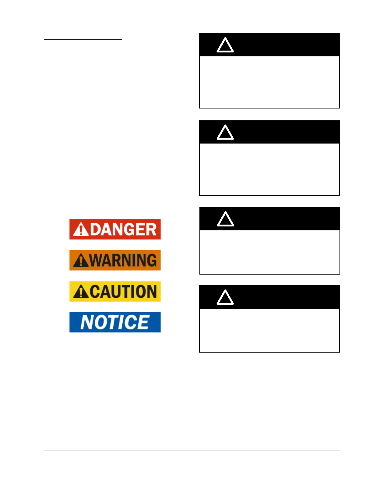
ANSI Z535.5 Definitions:
DANGER: Indicate[s] a hazardous situation which, if
not avoided, will result in death or serious injury. The
signal word “DANGER” is to be limited to the most
extreme situations. DANGER [signs] should not be used
for property damage hazards unless personal injury risk
appropriate to these levels is also involved.
WARNING: Indicate[s] a hazardous situation which,
if not avoided, could result in death or serious injury.
WARNING [signs] should not be used for property
damage hazards unless personal injury risk appropriate
to this level is also involved.
CAUTION: Indicate[s] a hazardous situation which, if
not avoided, could result in minor or moderate injury.
CAUTION [signs] without a safety alert symbol may be
used to alert against unsafe practices that can result in
property damage only.
NOTICE: [this header is] preferred to address practices
not related to personal injury. The safety alert symbol
shall not be used with this signal word. As an
alternative to “NOTICE” the word “CAUTION” without
the safety alert symbol may be used to indicate a
message not related to personal injury.
!
WARNING
Electrical shock hazard.
Have a properly trained individual perform
these tasks.
Failure to do so could result in electric shock
or death.
!
WARNING
Fire hazard.
Maintain minimum 1/4" clearance between the
supply ange and combustible materials.
Failure to do so could result in re causing
damage, injury or death.
!
WARNING
Heavy item hazard.
Use more than one person to handle unit.
Failure to do so could result in unit damage or
serious injury.
!
CAUTION
Cut hazard.
Wear gloves to avoid contact with sharp
edges.
Failure to do so could result in personal injury.
Manual 2100-670
Page 5 of 32
Page 6
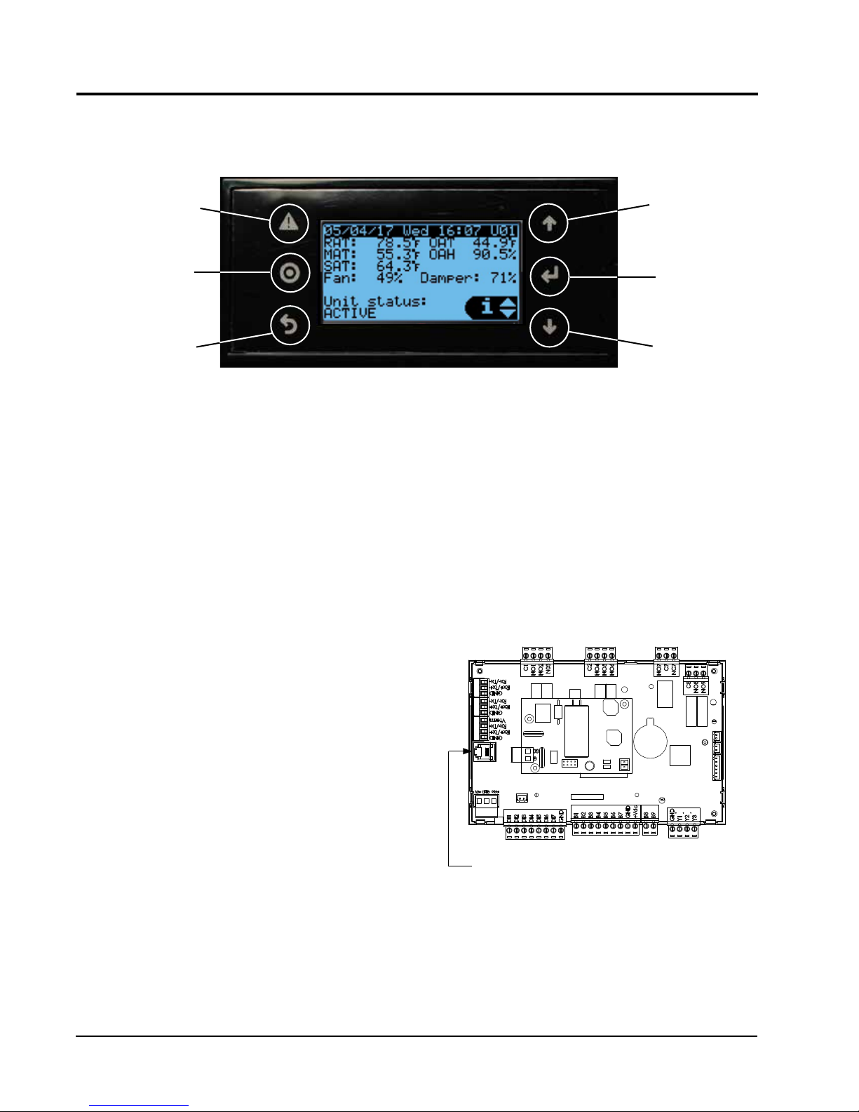
USING THE TEC-EYE
TEC-EYE (Bard P/N 8301-059) Display and Interface (Status Screen Shown)
TM
FIGURE 1
ALARM KEY
MENU KEY
ESCAPE KEY
ALARM KEY
Allows viewing of active alarms
Silences audible alarms
Resets active alarms
MENU KEY
Allows entry to Main Menu
ESCAPE KEY
Returns to previous menu level
Cancels a changed entry
TEC-EYE Hand-Held Diagnostic Tool
The microprocessor control used in the FUSION-TEC
wall-mount air conditioners allows for complete control
and monitoring through the use of the provided TECEYE hand-held monitor. This comprehensive service
tool utilizes the latest in state-of-the-art technology
including a large, easy-to-read backlit LCD graphic
display.
The menu driven interface provides users the ability
to scroll through two menu levels: Quick Menu and
Main Menu. The menus permit the user to easily view,
control and configure the unit.
The controller is completely programmed at the factory;
the default setpoints and their ranges are easily viewed
and adjusted from the TEC-EYE display. The program
and operating parameters are permanently stored
on FLASH-MEMORY in case of power failure. The
controller is designed to manage temperature levels to
a user-defined setpoint via control output signals to the
wall mount air conditioning system.
The TEC-EYE connects to the wall-mount unit control
board via an RJ11 modular phone connector as shown
in Figure 2.
UP KEY
ENTER KEY
DOWN KEY
UP KEY
Steps to next screen in the display menu
Changes (increases) the value of a modifiable field
ENTER KEY
Accepts current value of a modifiable field
Advances cursor
DOWN KEY
Steps back to previous screen in the display menu
Changes (decreases) the value of a modifiable field
FIGURE 2
TEC-EYE Connection to Unit Control
Modular Phone Connector for
TEC-EYE Hand-Held Diagnostic Tool
NOTE: Screenshots shown in this manual reflect
default settings (when applicable).
When not being used, the TEC-EYE hand-held
diagnostic tool should be stored inside or near the
LV1000 controller. Do not let the TEC-EYE leave the
shelter.
Manual 2100-670
Page 6 of 32
Page 7
TEC-EYE Menu Structure
Quick Menu
Setpoints
Information
Alarm Log
Main Menu
System Configuration
Advanced System Configuration
I/O Configuration
On/Off
Alarm Logs
Settings
Logout
In addition to the menu structure above, there are also
Status and Alarm screens.
TEC-EYE Acronyms
MAT – Mixed air temperature
RAT – Return air temperature
OAT – Outdoor air temperature
OAH – Outdoor air humidity
Blower – Indoor blower status
Damper – Free cooling damper position status
CL1 – Compressor stage 1 status
CL2 – Compressor stage 2 status
H1 – Heater stage 1 status
H2 – Heater stage 2 status
ODP – Calculated outdoor dew point
FC – Free cooling status
RN – Component run time in minutes in last hour
ST – Number of start requests in last hour
NOTE: Digital refers to On/Off whereas analog is a
variable input.
Status Screen
The Status screen is the default start-up screen and
also the return screen after 5 minutes of no activity.
The screen can be accessed any time by pressing the
ESCAPE key repeatedly.
The wall-mount unit address is displayed in the upper
right corner on the Status screen (see Figure 1). The
Status screen also shows the current date, time, return
air temperature, mixed air temperature, outdoor air
temperature, outdoor humidity and outdoor dew point
conditions. Blower, damper and unit status are also
displayed. See Table 1 for wall-mount unit status
messages.
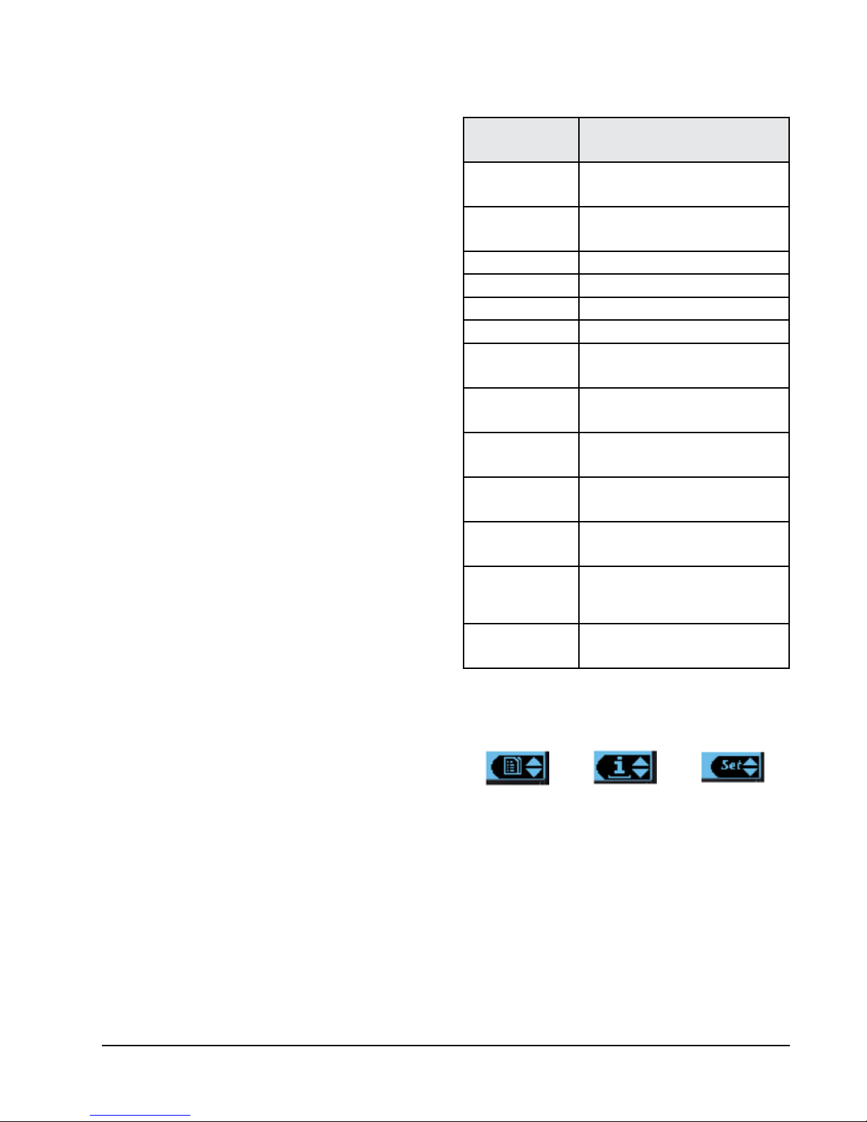
The Quick Menu is accessible from the Status screen.
Setpoints, Information and Data (Alarm) Log are
available through the Quick Menu. Pressing the UP or
DOWN keys while on the Status screen will change the
Quick Menu icon displayed (see Figure 3). Press the
ENTER key when the desired icon is displayed.
TABLE 1
Unit Status Messages
Message Description
Orphan Stby
Power Loss
Freecooling Unit is actively economizing
Cooling Unit is actively mechanical cooling
Heating Unit is actively heating
Dehum Mode Unit is actively dehumidifying
Off by Alarm
Off by Keyboard
Off by LV
Manual Mode
Test Mode System is performing a run test
Emergency Vent
Emergency Off
Unit is on and in orphan mode with
no calls for heating or cooling
Unit is operating under power loss
conditions (inverter model)
Unit has major fault preventing
operation
Unit has been turned off by
local user
Unit has been turned off by the
supervisory controller
There is an active override on the
system
Unit has active hydrogen alarm
and is actively exhausting the air to
outside
Unit has active smoke alarm and
Emergency Shutdown is active
FIGURE 3
Quick Menu Icons
Data Log Unit Information
Setpoints
Quick Menu
Setpoints
From this screen, the unit heating and cooling
setpoints can be changed.
The LV1000 setpoints will determine the cooling and
heating setpoints when communicating with the wall-
mount units. The unit cooling and heating setpoints
will determine the cooling and heating setpoints when
in stand alone mode.
If at any time the unit(s) loses communication with the
LV1000 controller, the unit(s) will go into stand alone
mode.
Manual 2100-670
Page 7 of 32
Page 8
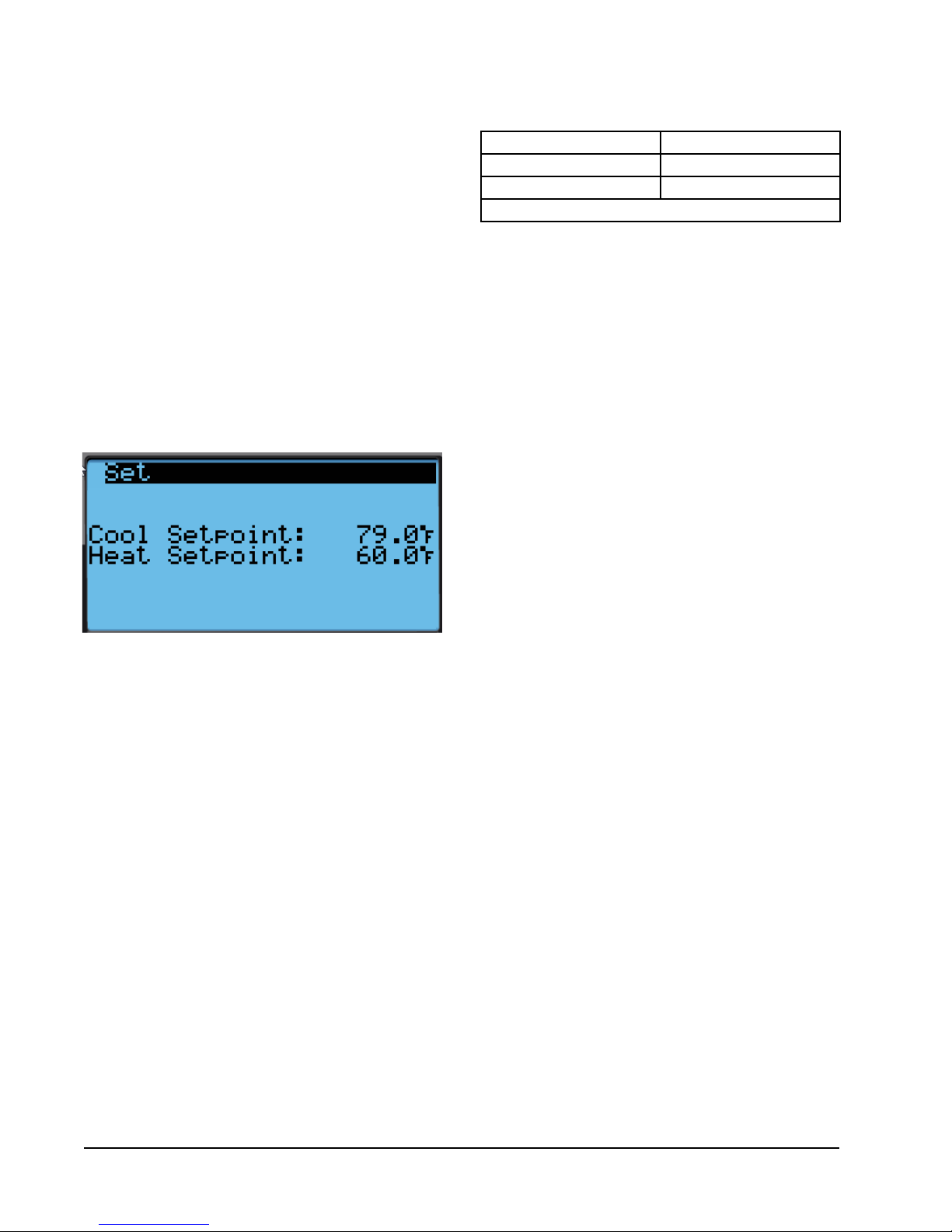
To verify or change the wall-mount unit cooling and
heating setpoints in stand alone mode:
1. Connect the TEC-EYE diagnostic tool to the control
board located in the unit.
2. From the Status screen, press UP or DOWN key
until Quick Menu displays Setpoints icon. Press
ENTER key.
3. Press ENTER key to scroll to the selected choice
(see Figure 48).
4. Press UP or DOWN key on desired value until value
displays correctly.
5. Press ENTER key to save and scroll to next
parameter.
6. Press ESCAPE key until Main Menu screen is
displayed.
FIGURE 4
Cool and Heat Setpoints
Information
These screens show unit demand, wall unit status,
serial/model number, hours, run hours, averages and
program version information.
Data (Alarm) Log
The alarm log screens show a log of each alarm. There
will be a log for when alarm occurred and if the alarm
auto clears, it will show when the alarm cleared.
TABLE 2
LV1000/TEC-EYE Passwords (Defaults)
User 2000
Technician 1313
Engineer 9254
Use UP or DOWN keys and ENTER key to enter password
Menu Screens and Password Levels
A System Config: A1-A10 User
B Adv Sys Config: B1-B4 Technician
C I-O Config: C1-C18 Technician
D On/Off: User
E Alarm Logs: User
F Settings:
Date/Time: Technician
Language: User
Network Config: Technician
Serial Ports: Technician
Initialization:
Clear Logs: User
System Default: Engineer
Restart: User
Parameter Config: Engineer
Alarm Export: User
G Logout: Used to log out of the current password
level. Entering back into the menu requires
password.
NOTE: Screenshots shown in this manual reflect
default settings (when applicable).
Manual 2100-670
Page 8 of 32
Page 9
OPERATION
Unit On/Off
The wall unit can be turned on and off from the TECEYE. Turning the unit off with the following instructions
will disable heating and cooling operation but may not
disable the blower. The blower may continue to run
if the unit or the LV1000 have the continuous blower
option enabled.
NOTE: Blower will run if the unit is in stand alone
mode.
To turn the unit on or off:
1. Press MENU key to go to the Main Menu screen.
2. Press UP or DOWN keys and ENTER key to enter
USER password 2000.
3. Press UP or DOWN keys to scroll to On/Off; press
ENTER key.
4. Press UP or DOWN keys to change value from On
to Off or from Off to On.
5. Press ESCAPE key several times to return to Main
Menu screen.
The wall unit may also be turned off by certain alarms
such as the smoke alarm input on the wall unit board
or the return air temperature sensor failure when not
connected to the LV1000.
Alarm Adjustment
Acknowledging/Clearing Alarms
Alarm conditions activate a red LED indicator that
backlights the ALARM function key. As an option, an
alarm condition may also be enunciated by an audible
alarm signal. An alarm is acknowledged by pressing the
ALARM key. This calls up alarm display screen(s) that
provide a text message detailing the alarm condition(s).
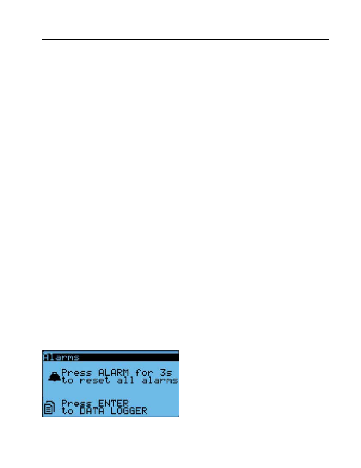
After an alarm condition is corrected, the alarm can be
cleared by pressing the ALARM key for 3 seconds.
To clear all alarms, navigate to the end of the alarm list
to the screen shown in Figure 5.
Stand Alone Mode
With the AC breakers turned on, each FUSION-TEC
wall-mount unit has the capability to run without the
LV1000 controller attached—this feature is called
stand alone or orphan mode. This keeps the shelter
between 60°F and 79°F (factory default settings) by
the use of the factory-installed return air sensor in
each wall-mount unit. In stand-alone mode, the wall
unit uses a continuous blower setting to circulate room
air into the return air inlet and uses the return air
temperature sensor to control room temperature.
The wall-mount unit can be turned on and off with
the TEC-EYE hand-held diagnostic tool. When ON is
chosen, the wall unit will heat or cool. The blower will
continue to run when OFF is chosen. If the wall unit is
turned OFF by the TEC-EYE while in stand alone mode
and power is interrupted, when repowered the blower
will not run until the wall unit is turned back ON by the
TEC-EYE (see Unit On/Off).
To change default setpoints, refer to Setpoints on page
7.
During installation, the ability to run in stand alone
mode allows deactivation of one of the existing, older
wall-mount units, while keeping the shelter cool
with the other unit still operating. Once the first of
the Bard FUSION-TEC wall-mount units is installed,
orphan mode can be enabled early in the installation—
keeping the climate inside the shelter stable and
the installers comfortable while the remainder of the
older equipment is removed and the remaining Bard
FUSION-TEC wall-mount units and LV1000 controller
are installed.
Additionally, should any or all of the FUSION-TEC
wall-mount units lose communication with the LV1000
controller (such as during maintenance), they will
continue to serve the shelter’s needs until a repair can
be made.
Temperature/Humidity Control
FIGURE 5
Clearing All Alarms
Temperature/Humidity Control Components
Return Air Temperature Sensor
The unit is equipped with a return air temperature
sensor to monitor the space temperature when the unit
is in stand alone mode. The return air sensor is located
in the upper part of the return opening in such a way
that it is exposed to the entering airstream. An alarm
signal will be sent to the LV controller if the return air
temperature sensor is disconnected. The temperature is
measured with a 10k ohm NTC thermistor.
This sensor can be verified and adjusted by:
1. Press MENU key to go to the Main Menu screen.
Manual 2100-670
Page 9 of 32
Page 10
2. Press UP or DOWN keys and ENTER key to enter
TECHNICIAN password 1313.
3. Press UP or DOWN keys to scroll to I/O Config;
press ENTER key.
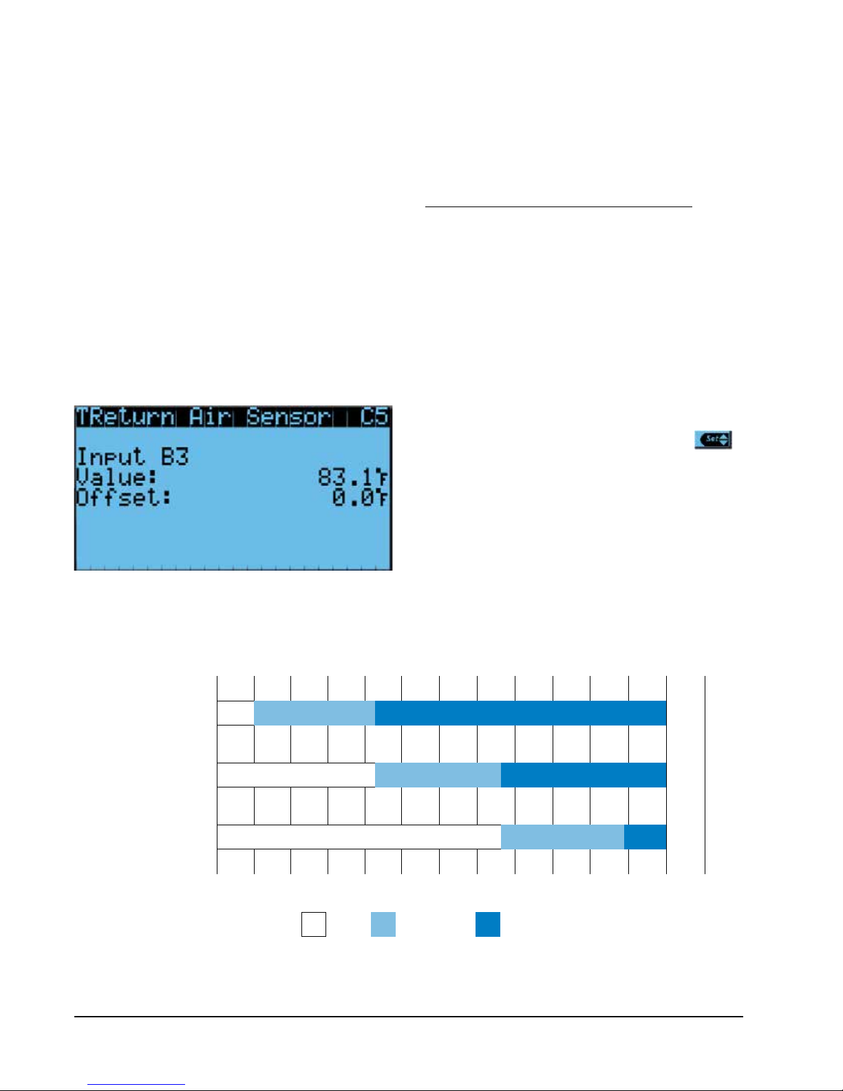
4. Press UP or DOWN keys to scroll to Return Air
Sensor (C5); press ENTER key.
5. Verify the measurement displayed on screen is
accurate (see Figure 6).
6. If the measurement needs to be adjusted, apply an
offset value by pressing ENTER to scroll to Offset.
7. Press UP or DOWN keys to adjust the offset.
8. The update will not take effect until the cursor is
moved out of the Offset parameter.
9. Once adjusted, press the ESCAPE key several
times to return to Main Menu screen.
FIGURE 6
Adjusting Return Air Sensor
Return Air Temperature Alarm
When the return air temperature sensor value is out of
range (-41.0 to 303.0°F), the controller will generate
a sensor failure alarm to indicate the sensor is not
working properly.
This alarm is fixed and cannot be adjusted.
Temperature/Humidity Control Operation
The unit utilizes a PID control loop for space control.
This control will compare the space temperature to
the space setpoint. Based on how far away from the
setpoint the temperature is, the loop will output a
cooling or heating capacity number between 0 and
100%. The unit will then take all of the available
cooling methods and distribute them evenly across the
0-100% range. The stages are then brought on as the
heating or cooling capacity reaches the percentage that
brings the stages on or off. There are separate setpoints
for cooling and heating.
To change or view the unit setpoint:
1. From the Status screen, press UP or DOWN key
until Quick Menu displays Setpoints icon ( ).
Press ENTER key.
2. Press ENTER key to scroll to Cool Setpoint or Heat
Setpoint (see Figure 4 on page 8).
3. Press UP or DOWN keys to change the value to
desired heating and/or cooling setpoint.
Cooling
The unit is equipped with 1 stage of freecooling and 2
stages of mechanical cooling (compressor and solenoid)
for a total of 3 cooling stages (see Figure 7).
FIGURE 7
Cooling w/Economizer
Freecooling
Compressor Stage 1
Compressor Stage 2
-10% 0%
Deadband(sometimes called a neutral zone or dead zone) is an interval of a signal domain or band where no action occurs
Manual 2100-670
Page 10 of 32
10% 20% 30% 40% 50% 60% 70% 80% 90% 100%
Off
Deadband On
110% 120%
Page 11

The unit is equipped with 1 stage of freecooling and
2 stages of mechanical cooling (compressor and
solenoid). However, the outdoor conditions are not
favorable for economizer operation so there are a total
of 2 cooling stages (see Figure 9).
Heating
The unit is equipped with 1 stage of electric heat (see
Figure 10).
Staging
The unit will stage the cooling components based on
the cooling demand referenced in the temperature
control. The unit will stage the economizer on first if
the indoor and outdoor conditions are favorable. The
compressor stage 1 will be enabled next as the demand
increases. Finally, the compressor stage 2 will be
enabled as the demand continues to increase.
The unit is only equipped with one stage of heat and
will turn on based on the heating demand.
FIGURE 9
Cooling w/No Economizer
To view unit stages:
1. From the Status screen, press UP or DOWN key
until Quick Menu displays Unit Information icon
( ). Press ENTER key.
2. The cooling and heating demand are visible on
this screen. The unit stages will display here when
active as FC, CL1, CL2 or H1 (see Figure 8).
FIGURE 8
Viewing Unit Stages
Compressor Stage 1
Compressor Stage 2
-10% 0%
Deadband(sometimes called a neutral zone or dead zone) is an interval of a signal domain or band where no action occurs
10% 20% 30% 40% 50% 60% 70% 80% 90% 100%
Off
Deadband On
110% 120%
FIGURE 10
Heating
Electric Heat
-10% 10% 30% 50% 70% 90% 110%
Off
Deadband On
Deadband(sometimes called a neutral zone or dead zone) is an interval of a signal domain or band where no action occurs
Manual 2100-670
Page 11 of 32
Page 12

Dehumidification
The unit uses a dehumidification sequence that does
not require the electric heat to run at the same time
as the compressor. Instead, the unit will turn on the
compressor to cool down to the heating setpoint.
Once the lower setpoint has been reached, the unit
will heat the space back up to the upper setpoint.
This cycle continues until the humidity level in the
shelter reaches an acceptable level. At this point,
the unit will revert back to normal operation. The
economizer will also be disabled while the unit is in
the dehumidification mode.
NOTE: This feature is dependent upon the LV1000
indoor humidity sensors and a command from
the LV to enter dehumidification mode. See
LV1000 Service Instructions 2100-673 for
adjustment of the dehumidification setpoint
and differentials.
Electronic Expansion Valve (EEV)
EEV Components
Electronic Expansion Valve
The electronic expansion valve is a stepper motor that
is controlled with a step output from the controller. The
valve is capable of 480 steps represented by a 0-100%
signal on the controller. The motor drives a needle valve
that regulates the flow of refrigerant.
Low Pressure Transducer
The unit has a low side pressure transducer installed
on the suction line between the evaporator coil
and compressor. The transducer is used for system
monitoring of low side system pressures. The sensor
is used with the suction temperature sensor to provide
a real time superheat calculation that determines the
EEV position.
This sensor can be verified and adjusted by:
1. Press MENU key to go to the Main Menu screen.
2. Press UP or DOWN keys and ENTER key to enter
TECHNICIAN password 1313.
3. Press UP or DOWN keys to scroll to I/O Config;
press ENTER key.
4. Press UP or DOWN keys to scroll to Suction Pr
Sensor (C11); press ENTER key.
5. Verify the measurement displayed on screen is
accurate (see Figure 11).
6. If the measurement needs to be adjusted, apply an
offset value by pressing ENTER to scroll to Offset.
7. Press UP or DOWN keys to adjust the offset.
8. The update will not take effect until the cursor is
moved out of the Offset parameter.
9. Once adjusted, press the ESCAPE key several
times to return to Main Menu screen.
FIGURE 11
Adjusting Low Pressure Sensor Values
Suction Pressure Alarm
When the suction temperature sensor value is out
of range (0-250 PSIG), the controller will generate
a sensor failure alarm to indicate the sensor is not
working properly.
This alarm cannot be adjusted.
Suction Temperature Sensor
The suction temperature sensor is used to calculate
superheat. The EEV uses this value to control the EEV.
The temperature is measured with a 10k ohm NTC
thermistor.
The suction temperature sensor measurement can be
verified and adjusted by:
1. Press MENU key to go to the Main Menu screen.
2. Press UP or DOWN keys and ENTER key to enter
TECHNICIAN password 1313.
3. Press UP or DOWN keys to scroll to I/O Config;
press ENTER key.
4. Press UP or DOWN keys to scroll to Suct Temp
Sensor (C9); press ENTER key.
5. Verify the measurement displayed on screen is
accurate (see Figure 12 ).
6. If the measurement needs to be adjusted, apply an
offset value by pressing ENTER to scroll to Offset.
7. Press UP or DOWN keys to adjust the offset.
8. The update will not take effect until the cursor is
moved out of the Offset parameter.
9. Once adjusted, press the ESCAPE key several
times to return to Main Menu screen.
Suction Temperature Alarm
When the suction temperature sensor value is out of
range (-41.0 to 303.0°F), the controller will generate
a sensor failure alarm to indicate the sensor is not
working properly.
This alarm cannot be adjusted.
Manual 2100-670
Page 12 of 32
Page 13

FIGURE 12
Adjusting Suction Temperature Sensor Values
EEV Operation
EEV Superheat Control
The electronic expansion valve (EEV) will open or close
to maintain 10° of superheat while the compressor is
running. When the compressor is not running, the valve
will close.
Low superheat protection will be active once the
superheat value is at or below 5°F. At this point,
the control will aggressively close the valve so that
superheat is maintained.
EEV Instructions for Vacuum, Reclaim, Charge Unit
The electronic expansion moves to the 0 position when
the unit is not actively cooling. The valve may need to
be manually positioned for service or troubleshooting.
The valve can be positioned by using a menu override.
To manually override the valve:
NOTE: The unit must be off to perform this override.
1. Press MENU key to go to the Main Menu screen.
2. Press UP or DOWN keys and ENTER key to enter
TECHNICIAN password 1313.
3. Press UP or DOWN keys to scroll to I/O Config;
press ENTER key.
4. Press UP or DOWN keys to scroll to TEEV Service
(C16); press ENTER key.
5. Press ENTER key to scroll to Enable (see Figure
13).
6. Press UP or DOWN key to change Disable to
Enable.
7. Press ENTER key to scroll to Position.
8. Press UP or DOWN keys to adjust to the desired
value.
9. Press ENTER key to save.
10. Press the ESCAPE key several times to return to
Main Menu screen.
FIGURE 13
Overriding EEV Output
The valve can also be opened or closed using the EEV
service tool (Bard Part # 2151-021). This magnetic
EEV service tool (shown in Figure 14) is used to
Electronic Expansion Valve (EEV) and Service Tool
FIGURE 14
Manual 2100-670
Page 13 of 32
Page 14

manually open the EEV. To do this, remove the EEV
stator coil (red color with retaining nut on top), slide
the magnetic tool over the shaft where the stator was
removed and turn in a clockwise direction to open the
valve to the full open position (directional arrows are
provided on the tool). Opening the valve to the full
open position will aid in the refrigerant reclamation and
evacuation processes.
Following the above procedure, reapply the EEV stator
coil and retaining nut. Upon powering the unit back up,
the control board will automatically drive the EEV back
to the fully shut position, and then back to the 20%
open position prior to starting the compressor back
up. Once the compressor starts, the control board will
again modulate the EEV position to control the system
superheat.
System Pressures
To view system pressure and temperatures during this
process:
1. From the Status screen, press UP or DOWN key
until Quick Menu displays Unit Information icon
( ). Press ENTER key.
2. Press UP or DOWN keys to scroll to EEV 1 Circuit
and EVD 1 Compressor screens.
3. Reference the Pressures and Temperatures on EVD
1 Compressor and the Superheat and Subcooling
on EEV 1 Circuit.
Additional EEV Alarms
Low Superheat Alarm
This alarm will become active when the calculated
superheat goes below 5°F. This alarm will clear itself
when the condition is no longer present.
This alarm cannot be adjusted.
Indoor Airflow
Indoor Airflow Components
Blower
The unit is equipped with a blower that is driven by an
electronically commutated motor (ECM). This blower
is controlled by a 0-10v signal provided from the
controller. This 0-10v signal is converted to a PWM
signal with an adapter. This blower uses a 10" diameter
wheel operating between 250-1400 rpm.
The blower output can be put into an override mode for
verification or troubleshooting. To put the blower into
override:
1. Press MENU key to go to the Main Menu screen.
2. Press UP or DOWN keys and ENTER key to enter
TECHNICIAN password 1313.
3. Press UP or DOWN keys to scroll to I/O Config;
press ENTER key.
4. Press UP or DOWN keys to scroll to Blower Fan
(C13); press ENTER key.
5. Press ENTER key to scroll to Blower OV Speed (see
Figure 15).
6. Press UP or DOWN keys to adjust the speed to the
desired output (see Table 3).
7. Press ENTER key to scroll to Override.
8. Press UP or DOWN key to change Disabled to
Enabled.
9. Press ENTER key to save.
10. Press the ESCAPE key several times to return to
Main Menu screen.
FIGURE 15
Putting Blower Output into Override Mode
TABLE 3
Blower Speeds
Mode
Freezestat Active 80.0 8.0 v 2260
High Sensible Full
Load Cooling
High Sensible Part
Load Cooling
Standard Full
Load Cooling
Standard Part
Load Cooling
Economizer Speed 45.0 4.5 v 1600
Heating 35.0 3.5 v 1335
Dehumidification
Mode
Speed
Percentage
75.0 7.5 v 2180
50.0 5.0 v 1705
55.0 5.5 v 1830
35.0 3.5 v 1335
35.0 3.5 v 1335
Controller
Output Volts
CFM
Manual 2100-670
Page 14 of 32
Page 15

TABLE 4
Rated Airflow
FIGURE 16
Adjusting Air Flow Alarm Delay
Nominal Rated CFM
High Low
1800 1400 .10
Nominal Rated ESP
TABLE 5
Indoor Blower Performance
Speed High Low
ESP
(Inch H20)
0.1
Dry Coil Wet Coil Dry Coil Wet Coil
1885 1800 1470 1400
TABLE 6
Maximum ESP of Operation
Electric Heat Only
Model Static Pressure*
-A0Z
-A05
-B0Z
-B06
* Unit is rated for free blow non-ducted
operation with SGR-5W Supply Grille
and RGR-5W Return Grille.
.00"
.00"
.00"
.00"
Differential Airflow Switch
The unit is equipped with a differential pressure airflow
switch to monitor the blower (see Figure 17). If the
blower is turned on and the switch doesn't close to
indicate there is differential pressure between the inlet
and outlet of the blower, an alarm will be generated.
The switch should be set at .20.
FIGURE 17
Dirty Filter Switch and Blower Status Switch
Blower Status Alarm
If the blower is commanded on and the fan status
switch (differential pressure) has not indicated the fan
is running within 45 seconds, the system will generate
an alarm.
This alarm is just a notification and will clear itself
when the conditions are no longer present.
To adjust the air flow alarm delay:
1. Press MENU key to go to the Main Menu screen.
2. Press UP or DOWN keys and ENTER key to enter
USER password 2000.
3. Press UP or DOWN keys to scroll to System Config;
press ENTER key.
4. Press UP or DOWN keys to scroll to Alarm Setup
(A8); press ENTER key.
5. Press ENTER key to scroll to Air Flow Alarm Del
(see Figure 16).
6. Press UP or DOWN keys to change to the desired
value.
7. Press ENTER key to save the value.
Differential airflow status can be viewed by:
1. Press MENU key to go to the Main Menu screen.
2. Press UP or DOWN keys and ENTER key to enter
TECHNICIAN password 1313.
3. Press UP or DOWN keys to scroll to I/O Config;
press ENTER key.
4. Press UP or DOWN keys to scroll to Digital In
Config (C2); press ENTER key.
5. Reference 7 NoAir row and Val column (see Figure
18 on page 16).
Manual 2100-670
Page 15 of 32
Page 16

FIGURE 18
AIRSTREAM BEFORE FILTER
TUBE LOCATED IN
COVER
REMOVE COVER
SCREW TO
TUBE LOCATED IN
AIRSTREAM AFTER FILTER
ADJUSTMENT
INDICATOR ARROW
ADJUSTMENT
KNOB
FILTER
LIGHT
Verifying Differential Airflow Status
Filters
The unit is equipped with two (2) 20" x 30" x 2" MERV
8 filters. The filters slide into position making them easy
to service. The filters can be serviced from the outside
by removing either the right or left filter access panel.
FIGURE 19
Dirty Filter Switch and Filter Indicator Light
Dirty Filter Switch
These units are equipped with a differential pressure
switch to indicate when the filter(s) needs to be
replaced (see Figure 17). The dirty filter switch
measures the pressure difference across the filter
through silicone tubing routed to the blower and vent
areas of the unit.
The switch circuit consists of a normally open filter
pressure switch. The switch will open when the
pressure differential goes above the setting indicated
on the dial. When the pressure difference returns below
the setting on the dial, the switch will close.
Adjustment of dirty filter switch may be necessary to
ensure proper operation. See Figure 19 and Table 7 to
aid in setting the filter switch to operate at different
percentages of filter blockage.
MIS-3901
Manual 2100-670
Page 16 of 32
Page 17

TABLE 7
Filter Switch Pressure Settings
Unit Filter Blockage % 0% 10% 20% 30% 40% 50% 60% 70%
HR58APA
(Default) High S/T
HR58APA
Standard Airflow
All units tested equipped with MERV 8 filters. Appropriate supply (SG) and return (RG) grilles installed during testing. Pressure
switch adjustment may be necessary due to variations in filter type, installation and room pressure.
Bard recommends the filter switch be set at 50% filter blockage or less. Higher settings may significantly hinder unit
performance.
Dirty Filter Alarm
The wall unit is equipped with a differential pressure
switch input to the controller. When the switch
indicates a dirty filter, the controller will generate an
alarm. Once the condition is no longer present, the
alarm will automatically clear. Additionally, an indicator
Switch Static Setting 0.40 0.50 0.60 0.70 0.75 0.80 0.90 1.00
Evaporator Airflow % 100% 98.7% 98.1% 97.5% 91.7% 81.3% 79.1% 78.6%
Switch Static Setting 0.30 0.35 0.40 0.45 0.50 0.65 0.70 0.90
Evaporator Airflow % 100% 99.8% 99% 98.5% 96.8% 89.9% 84% 82.2%
NOTE: This input is automatically configured by
the model number and cannot be enabled or
disabled on this screen.
FIGURE 20
Verifying Freeze Switch Status
light will be turned on with the alarm and turned off
when the alarm clears.
The threshold of this alarm is adjusted by changing the
settings on the switch (see Table 7).
Filter Indicator Light
These units are equipped with a 24v indicator light
mounted on side of unit that displays the current status
of the filter (see Figure 19). When the light is on, the
filter needs to be replaced. Once the filter(s) has been
changed, the indicator light will turn off.
Freezestat
These units are equipped with a switch that monitors
the temperature of the refrigerant line leaving the
evaporator coil. To prevent the coil from freezing
and potentially allowing liquid refrigerant from the
evaporator to enter the compressor, the switch will open
when the temperature at this sensor is between 26.5°F
and 37.5°F and close again when the temperature is
between 49.5°F and 64.5°F.
This switch can be verified by:
1. Press MENU key to go to the Main Menu screen.
2. Press UP or DOWN keys and ENTER key to enter
TECHNICIAN password 1313.
3. Press UP or DOWN keys to scroll to I/O Config;
press ENTER key.
4. Press UP or DOWN keys to scroll to Digital In
Config (C1); press ENTER key.
5. Reference 5 Freeze row and Val column (see Figure
20).
6. This value will display ON when the freezestat
has tripped and OFF when the freezestat is in its
Freezestat Alarm
When the freezestat digital input indicates a low
temperature event has occurred for longer than 120
seconds, the controller will generate a freezestat alarm.
This will then change the blower to high speed and
turn off the compressor for a minimum of 300 seconds.
The blower speed will return to normal once the alarm
condition has been removed. The compressor will start
again when the freezestat indicates no alarm and 300
seconds has passed. Once the condition is no longer
present, the alarm will automatically clear.
To adjust the freezestat alarm delay:
1. Press MENU key to go to the Main Menu screen.
2. Press UP or DOWN keys and ENTER key to enter
USER password 2000.
3. Press UP or DOWN keys to scroll to System Config;
press ENTER key.
4. Press UP or DOWN keys to scroll to Alarm Setup
(A7); press ENTER key.
5. Press ENTER key to scroll to FreezeStat Alarm
Delay (see Figure 21 on page 18).
normal position.
Manual 2100-670
Page 17 of 32
Page 18

6. Press UP or DOWN keys to change to the desired
value.
7. Press ENTER key to save the value.
FIGURE 21
Adjusting Freezestat Alarm Delay
4. Press UP or DOWN keys to scroll to Condenser Fan
(C15); press ENTER key.
5. Reference Fan Speed parameter for the current
output to the condenser fan (see Figure 22).
FIGURE 22
Verifying Condenser Fan Output
Indoor Airflow Operation
Blower Speed Control
The blower is capable of changing speeds to best match
the requirements of the system depending on which
mode the system is in (see Table 3 on page 14).
The unit will automatically switch to the required
speed for each mode. High sensible mode and
dehumidification mode are both communicated
separately from the LV. For more information on the
high sensible command from LV, please see LV1000
Service Instructions 2100-673.
Additional Indoor Airflow Alarms
Supply Air Temperature Alarm
When the supply air temperature sensor value is out of
range (-41.0 to 303.0°F), the controller will generate
a sensor failure alarm to indicate the sensor is not
working properly.
This alarm is fixed and cannot be adjusted.
Condenser Fan
Condenser Fan Components
Condenser Fan
The unit is equipped with a condenser fan that is
driven by an electronically commutated motor (ECM).
This fan is controlled by a 0-10v signal provided from
the controller. The fan operates between 100-1200
rpm.
To view the output of the condenser fan:
1. Press MENU key to go to the Main Menu screen.
2. Press UP or DOWN keys and ENTER key to enter
TECHNICIAN password 1313.
3. Press UP or DOWN keys to scroll to I/O Config;
press ENTER key.
If required, the condenser fan output can be manually
set for 5 minutes for troubleshooting purposes.
While looking at Condenser Fan (C15) screen:
1. Press ENTER key to scroll to Fan OV Speed (see
Figure 22).
2. Press UP or DOWN keys to change the value to the
desired override speed.
3. Press ENTER key to save the value and move
cursor to the Override parameter.
4. Press UP or DOWN keys to change the value from
Disabled to Enabled.
5. The fan should now run at the selected speed. The
output can be verified by again referencing the Fan
Speed parameter.
The override will last for 5 minutes or until the Override
parameter is set to Disabled again.
Due to design considerations of the condenser section
of the wall unit, placement/clearance of the motor/
fan blade is critical to heat dispersal. Should a change
of motor or fan blade be necessary, see Figure 23 for
proper clearance adjustment.
FIGURE 23
Fan Blade Setting
1.75"
Manual 2100-670
Page 18 of 32
Page 19

High Pressure Transducer
The unit has a high side pressure transducer installed
on the liquid line between the condenser and electronic
expansion valve (EEV). The transducer is used for
system monitoring of high side system pressures.
This information is used to indicate when outdoor coil
cleaning is necessary based on outdoor conditions and
system pressures. The sensor is also used to adapt
the condenser fan speed for high and low ambient
conditions.
The high pressure input can be verified and adjusted by:
1. Press MENU key to go to the Main Menu screen.
2. Press UP or DOWN keys and ENTER key to enter
TECHNICIAN password 1313.
3. Press UP or DOWN keys to scroll to I/O Config;
press ENTER key.
4. Press UP or DOWN keys to scroll to Disch Pr
Sensor (C10); press ENTER key.
5. Verify the measurement displayed on screen is
accurate (see Figure 24).
6. If the measurement needs to be adjusted, apply an
offset value by pressing the ENTER key to scroll to
Offset.
7. Press UP or DOWN keys to adjust the offset. The
update will not take effect until the cursor is
moved out of the offset parameter.
8. Once adjusted, the ESCAPE key several times to
return to Main Menu screen.
refrigerant leaving the condenser and entering the EEV.
The temperature is measured with a 10k ohm NTC
thermistor.
The discharge temperature sensor can be verified and
adjusted by:
1. Press MENU key to go to the Main Menu screen.
2. Press UP or DOWN keys and ENTER key to enter
TECHNICIAN password 1313.
3. Press UP or DOWN keys to scroll to I/O Config;
press ENTER key.
4. Press UP or DOWN keys to scroll to Disch Temp
Sensor (C3); press ENTER key.
5. Reference the Value to verify the temperature (see
Figure 25).
6. If an offset needs to be applied, press ENTER key
to scroll to Offset.
7. Press UP or DOWN keys to change the offset to
desired value.
8. Press ENTER key to save.
9. Press ESCAPE key several times to return to Main
Menu screen.
FIGURE 25
Adjusting Discharge Temperature Input
FIGURE 24
Adjusting High Pressure Input
High Pressure Transducer Alarm
When the high pressure transducer sensor value is out
of range (0-650 PSIG), the controller will generate
a sensor failure alarm to indicate the sensor is not
working properly.
This alarm is fixed and cannot be adjusted.
Discharge Temperature Sensor
The unit is equipped with a liquid line temperature
sensor to monitor the temperature of the liquid
Condenser Fan Operation
Condenser Fan Speed Control
The condenser fan motor maintains its high efficiency
across a wide operating range. The result is a
significant reduction in energy use when the motor is
run at reduced speeds. See Table 8 on page 20.
Manual 2100-670
Page 19 of 32
Page 20

TABLE 8
Condenser Fan Speeds
Mode Speed %
High Ambient 71 – 100 7.1 v – 10.0 v
Low Ambient 25 – 71 2.5 v – 7.1 v
Normal 71 7.1 v 2726
Controller
Output Volts
CFM
2726 –
3703
1130 –
2726
High Pressure Control
Condenser Fan Speed
When the discharge pressure reaches 590 PSI, the
condenser fan will begin to speed up to attempt to
bring the pressure back down. The speed will continue
to ramp up until the discharge pressure reaches 630
PSI. At this point, the fan will be operating at full
speed, moving as much air as possible.
Second Stage Drop Out
The second stage of cooling will be disabled when the
discharge pressure reaches 620 PSI to reduce the
required condenser airflow.
High Pressure Cut Out
See chart in Figure 26.
Low Pressure Control
When the discharge pressure reaches 375 PSI, the
condenser fan will begin to slow down to attempt to
bring the pressure back up. The speed will continue
to ramp down until the discharge pressure reaches
340 PSI. At this point, the fan will be operating at
minimum speed, moving as little air as possible.
If the discharge pressure continues to go down to
250 PSI, the condenser fan will turn off. The fan
will remain off with the compressor running until the
pressure reaches 340 PSI. The fan will then turn back
on at the minimum speed. The fan will continue to run
at the minimum speed until the pressure drops again or
starts to rise above the 340 PSI setpoint and begins to
speed up again.
Additional Condenser Fan Alarms
Dirty Condenser Coil Alarm
The unit will continuously monitor system conditions
to determine if the condenser coil is dirty or blocked.
If the system monitors three consecutive cooling
cycles that indicate a dirty condenser coil, an alarm
will be generated. This alarm is a notification and will
automatically reset when conditions are no longer
present. The end user has the ability to adjust how
dirty the coil gets before an alarm is generated and how
many consecutive cycles before the alarm is triggered.
To change these settings:
1. Press MENU key to go to the Main Menu screen.
2. Press UP or DOWN keys and ENTER key to enter
TECHNICIAN password 1313.
3. Press UP or DOWN keys to scroll to Adv System
Config; press ENTER key.
4. Press UP or DOWN keys to scroll to Dirty Cond
Alarm (B4); press ENTER key.
Manual 2100-670
Page 20 of 32
FIGURE 26
Pressure Control
Page 21

5. Press ENTER key to scroll to Alarm Threshold (see
Figure 27).
6. Press UP or DOWN keys to adjust the % restriction
to desired level.
7. Press ENTER key to save value and move the
cursor to Trips before alarm.
8. Press UP or DOWN keys to change the Trips before
alarm to the desired value.
9. Press ENTER key to save.
10. Press ESCAPE key several times to return to Main
Menu screen.
FIGURE 27
Adjusting Dirty Condensor Coil Alarm Settings
Compressor
Compressor Components
Compressor
Three Phase Scroll Compressor Start Up Information
Scroll compressors, like several other types of
compressors, will only compress in one rotational
direction. Direction of rotation is not an issue with
single phase compressors since they will always start
and run in the proper direction.
However, three phase compressors will rotate in either
direction depending upon phasing of the power.
Since there is a 50-50 chance of connecting power
in such a way as to cause rotation in the reverse
direction, verification of proper rotation must be made.
Verification of proper rotation direction is made by
observing that suction pressure drops and discharge
pressure rises when the compressor is energized.
Reverse rotation also results in an elevated sound level
over that with correct rotation, as well as substantially
reduced current draw compared to tabulated values.
Verification of proper rotation must be made at the time
the equipment is put into service. If improper rotation
is corrected at this time, there will be no negative
impact on the durability of the compressor. However,
reverse operation for over 1 hour may have a negative
impact on the bearing due to oil pump out.
NOTE: If compressor is allowed to run in reverse
rotation for an extended period of time, the
compressor’s internal protector will trip.
All three phase compressors are wired identically
internally. As a result, once the correct phasing is
determined for a specific system or installation,
connecting properly phased power leads to the same
Fusite terminal should maintain proper rotation
direction.
The direction of rotation of the compressor may be
changed by reversing any two line connections to the
unit.
Compressor Control Module (CCM)
The compressor control module is a low voltage
monitoring device necessary to monitor power and
indicate a low incoming voltage situation caused by
inadequate shore power or generator operation. The
monitoring device protects the unit against compressor
contactor “chatter” and reverse compressor rotation
during these situations.
Compressor protection device has an adjustable
30-second to 5-minute timer (red-dial). This module
features a delay-on-make for initial start up (or anytime
power is interrupted) for a minimum 2 minutes plus
10% of the red-dial setting. There is no delay during
routine operation of the unit. The compressor control
module also monitors the high pressure switch, and
will allow one automatic retry (after soft lockout delay)
before disabling the compressor in a hard lockout
(requires manual reset). If hard lockout does occur,
the ALR terminal on the CCM will become active with
24v, which will power the high pressure relay within
the wall unit. The relay contacts are monitored by the
unit controller. If the CCM indicates an alarm to the
wall unit controller, an alarm will be generated and the
compressor will be locked out by the controller.
NOTE: The controller will remove cooling call on the Y
terminal of the CCM, reseting it almost instantly.
The compressor remains locked out by the
controller until manually cleared.
Switch is jumpered in this application. Instead, the low
pressure transducer is used for low pressure monitoring.
High Pressure Safety Switch
All units have a high pressure switch as a safety device.
This device will open when pressure in the system
reaches 650 PSIG. The sensor is directly connected to
the dedicated compressor control module. This module
will disable any call for cooling if the pressure is above
this limit. If tripped, the high pressure switch can be
reset by turning the output off and then back on again.
Refrigerant High Pressure Alarm
When the wall unit receives a signal from the
compressor control module (CCM) indicating a high
pressure event, the wall unit will generate an alarm.
Manual 2100-670
Page 21 of 32
Page 22

Upon receiving the alarm, the wall unit will remove
the “Y” call from the CCM, resetting the status of the
CCM. The alarm will stay present on the wall unit until
manually cleared.
In addition to the CCM, the discharge pressure
transducer is used to prevent a high pressure event.
When the discharge pressure is above the discharge
pressure alarm setpoint (set 30 pounds below high
pressure switch, which is 650), the system will disable
stage 2 of mechanical cooling.
Phase Monitor
Used only on three phase equipment, the phase
monitor is a compressor protection device that will
prohibit operation of the compressor if the device senses
a possible reverse-rotation situation due to incorrect
phasing. On a call for compressor (and only compressor),
the device will check incoming phase, check for severe
voltage imbalance and check for proper frequency.
Under nominal conditions, a green LED light will show
on the face of the monitor. If there is improper phasing,
voltage imbalance or frequency deviation, the device will
show a red LED light and prohibit compressor operation.
If a fault condition occurs, reverse two of the supply
leads to the unit. Do not reverse any of the unit factory
wires as damage may occur.
7. Press ENTER key to save value and move the
cursor to next parameter or top of screen.
8. Press ESCAPE key several times to return to Main
Menu screen.
The address-based delay only applies to the wall unit
when in stand alone mode. The controller will delay the
unit compressor based on the value entered on screen
B2 multiplied by the unit address. This is intended to
keep multiple units from starting their compressors
at the same time when there is a quick change in the
load. When connected to the LV, this is taken care of by
LV logic.
FIGURE 28
Adjusting Compressor Delays
Compressor Operation
The compressor will be enabled when the unit (in stand
alone mode) or LV provide a cooling stage 1 call. The
compressor call from the controller has several delays
that may affect the start or stop time of the compressor
in regards to the cooling demand. The compressor has
a minimum on time of 180 seconds to prevent short
cycling the compressor. The compressor also has a
minimum off time of 120 seconds to prevent start
ups before the pressure in the refrigeration system
equalizes. When the second stage is engaged, it also
has a minimum run time of 120 seconds to allow the
system to stabilize before returning to single stage or
shutting down.
These delays can be changed by:
1. Press MENU key to go to the Main Menu screen.
2. Press UP or DOWN keys and ENTER key to enter
TECHNICIAN password 1313.
3. Press UP or DOWN keys to scroll to Adv System
Config; press ENTER key.
4. Press UP or DOWN keys to scroll to Unit Config
(B2); press ENTER key.
5. Press ENTER key to scroll to Min On, Min Off,
Min On Same, Unloader Del or Address Delay (see
Figure 28).
6. Press UP or DOWN keys to change the value.
Additional Compressor Alarms
Refrigerant Low Pressure Alarm
When the low pressure transducer indicates a pressure
value less than the low pressure alarm setpoint of
40 PSIG and there is an active call for cooling,
the controller will disable the compressor (after a
180-second delay). NOTE: The second call will be
delayed based on the delay off value mentioned in the
compressor section. The controller will try to run the
refrigeration system two (2) times within 900 seconds
before the alarm will lock the compressor out. This
alarm needs to be manually cleared before compressor
operation will resume.
To adjust the low pressure alarm settings:
1. Press MENU key to go to the Main Menu screen.
2. Press UP or DOWN keys and ENTER key to enter
USER password 2000.
3. Press UP or DOWN keys to scroll to System Config;
press ENTER key.
4. Press UP or DOWN keys to scroll to Alarm Setup
(A6); press ENTER key.
5. Press ENTER key to scroll to Delay to adjust how
long the compressor waits before turning the
compressor off (see Figure 29).
6. Press UP or DOWN keys to adjust the time delay.
7. Press ENTER key to scroll to Two Count Del.
Manual 2100-670
Page 22 of 32
Page 23

8. Press UP or DOWN keys to adjust the delay value.
9. Press ENTER key to save.
10. Press the ESCAPE key several times to return to
Main Menu screen.
FIGURE 29
Adjusting Low Pressure Alarm Settings
Economizer
Economizer Components
Actuator
The actuator rotates up to 90° based on a 2-10v signal
sent to it by the controller. The actuator is rated at
44 lb-in and is spring return when power is lost. This
component is what opens and closes the damper blade.
To verify the output from the controller to the actuator:
1. Press MENU key to go to the Main Menu screen.
2. Press UP or DOWN keys and ENTER key to enter
TECHNICIAN password 1313.
3. Press UP or DOWN keys to scroll to I/O Config;
press ENTER key.
4. Press UP or DOWN keys to scroll to Damper
Override (C14); press ENTER key.
5. Reference the Damper Position for the current
output to the damper (see Figure 2.30).
6. To override the current position, press ENTER key
to scroll to Damper OV Pos.
7. Press UP or DOWN keys to change the value to the
desired output.
8. Press ENTER key to save the value and move
cursor to Override.
9. Press UP or DOWN keys to change the value from
Disabled to Enabled.
10. The Damper Position will update with the new
override value and the damper will travel to that
position.
NOTE: This override will last for 5 minutes or until the
Override is changed back to Disabled.
FIGURE 30
Damper Override
Dust Sensor
The unit has a dust sensor installed near the outdoor
air inlet. The dust sensor checks for excessive
particulates in the outdoor air, and will close the
economizer if the dust is excessive. The sensor uses a
PWM signal converted to 0-5v output to the controller.
To ensure proper performance, cleaning may be
required. Vacuuming or blowing the dust off the sensor
with forced air is recommended. Avoid inserting any
objects into the sensor.
The dust sensor can be verified by:
1. Press MENU key to go to the Main Menu screen.
2. Press UP or DOWN keys and ENTER key to enter
TECHNICIAN password 1313.
3. Press UP or DOWN keys to scroll to I/O Config;
press ENTER key.
4. Press UP or DOWN keys to scroll to Dust Sensor
(C8); press ENTER key.
5. Reference the Value for the current sensor reading
(see Figure 31 on page 24).
6. To apply an offset to the current reading, press
ENTER key to scroll to Offset.
7. Press UP or DOWN keys to adjust the value to the
desired value.
8. Press ENTER key to save the value and move
cursor to next parameter.
NOTE: The sensor can be disabled if required for
troubleshooting.
9. With the cursor on the Enable parameter, press
UP or DOWN keys to change the value from ON to
OFF.
10. Press ENTER key to save.
Manual 2100-670
Page 23 of 32
Page 24

FIGURE 31
Dust Sensor
FIGURE 32
Adjusting Dust Sensor Alarm Setpoint
Dust Sensor Failure Alarm
When the sensor reads a value that is outside of the
acceptable 0 to 100% RH range, an alarm will be
generated indicating the sensor has failed. This alarm
is just a notification and will not disable any other
features on the controller.
This alarm is fixed and cannot be adjusted.
Dust Limit Alarm
The controller has adjustable software setpoints
(default to 80%) to indicate dust levels are too high
and disable the economizer operation for 30 minutes.
This alarm is not communicated to the NOC. Once
the conditions are no longer present, the alarm will
automatically clear.
To adjust the dust sensor alarm setpoint:
1. Press MENU key to go to the Main Menu screen.
2. Press UP or DOWN keys and ENTER key to enter
USER password 2000.
3. Press UP or DOWN keys to scroll to System Config;
press ENTER key.
4. Press UP or DOWN keys to scroll to Alarm Setup
(A9); press ENTER key.
5. Press ENTER key to scroll to Setpoint (see Figure
32).
6. Press UP or DOWN keys to change to the desired
value.
7. Press ENTER key to save the value.
NOTE: When the temperature outside is measured
at or below 0°F, the dust sensor alarm will be
disabled to allow economizer operation. This
is done because the compressor is disabled
below 0°F and the system would not have the
capability to cool.
Damper Blade
The system utilizes three damper blades used to bring
in outdoor air and exhaust space air for economizer
operation. The damper blades are made of sheet metal
and are integrated into the equipment.
Damper Switch
The economizer utilizes a magnetic switch to determine
if the damper is operating correctly. This switch will be
closed when the damper is closed and open when the
damper is open.
To verify the status of the switch:
1. Press MENU key to go to the Main Menu screen.
2. Press UP or DOWN keys and ENTER key to enter
TECHNICIAN password 1313.
3. Press UP or DOWN keys to scroll to I/O Config;
press ENTER key.
4. Press UP or DOWN keys to scroll to Digital In
Config (C2); press ENTER key.
5. Reference the value located at 6 Damp row and Val
column (see Figure 33).
6. The input will display ON when the damper is
closed (reflecting closed circuit on damper switch)
and will display OFF when the damper is open
(reflecting open circuit on damper switch).
FIGURE 33
Damper Switch
Manual 2100-670
Page 24 of 32
Page 25

Damper Failed to Open Alarm
When the controller commands the economizer damper
actuator to a position other than 0% and the damper
switch indicates the damper is not open, after a delay
of 20 seconds the controller will generate a damper
failed to open alarm. This alarm is just a notification
and will not disable any features on the controller.
To adjust the damper failed to open delay:
1. Press MENU key to go to the Main Menu screen.
2. Press UP or DOWN keys and ENTER key to enter
USER password 2000.
3. Press UP or DOWN keys to scroll to System Config;
press ENTER key.
4. Press UP or DOWN keys to scroll to Alarm Setup
(A4); press ENTER key.
5. Press ENTER key to scroll to Open Delay (see
Figure 34).
6. Press UP or DOWN keys to change to the desired
value.
7. Press ENTER key to save the value.
FIGURE 34
Adjusting Damper Alarm Delay
5. Press ENTER key to scroll to Close Delay (see
Figure 34).
6. Press UP or DOWN keys to change to the desired
value.
7. Press ENTER key to save the value.
Outdoor Temperature and Humidity Combination
Sensor
The unit is equipped with a combination outdoor
temperature and humidity sensor to monitor
outdoor conditions for the economizer operation.
The temperature is measured with a 10k ohm NTC
thermistor. The humidity is measured with a humidity
sensor that outputs a 4-20mA signal to the controller.
The outdoor temperature can be verified by:
1. Press MENU key to go to the Main Menu screen.
2. Press UP or DOWN keys and ENTER key to enter
TECHNICIAN password 1313.
3. Press UP or DOWN keys to scroll to I/O Config;
press ENTER key.
4. Press UP or DOWN keys to scroll to Outdoor Air
Sensor (C4); press ENTER key.
5. Reference the Value to see the input of the sensor
(see Figure 35).
6. To apply an offset, press ENTER key to scroll to
Offset.
7. Press UP or DOWN keys to change to the desired
value.
8. Press ENTER key to save the value.
Damper Failed to Close Alarm
When the controller commands the economizer damper
actuator to the 0% position and the damper switch
indicates the damper is not closed, after a delay of 300
seconds the controller will generate a damper failed to
close alarm. This alarm is just a notification and will
not disable any features on the controller.
To adjust the damper failed to close delay:
1. Press MENU key to go to the Main Menu screen.
2. Press UP or DOWN keys and ENTER key to enter
USER password 2000.
3. Press UP or DOWN keys to scroll to System Config;
press ENTER key.
4. Press UP or DOWN keys to scroll to Alarm Setup
(A4); press ENTER key.
FIGURE 35
Outdoor Air Sensor
The outdoor humidity can be verified by:
1. Press MENU key to go to the Main Menu screen.
2. Press UP or DOWN keys and ENTER key to enter
TECHNICIAN password 1313.
3. Press UP or DOWN keys to scroll to I/O Config;
press ENTER key.
4. Press UP or DOWN keys to scroll to Outdoor Hum
Sensor (C7); press ENTER key.
Manual 2100-670
Page 25 of 32
Page 26

5. Reference the Value to see the input of the sensor
(see Figure 36).
6. To apply an offset, press ENTER key to scroll to
Offset.
7. Press UP or DOWN keys to change to the desired
value.
8. Press ENTER key to save the value.
FIGURE 36
Outdoor Humidity Sensor
Outdoor Temperature Sensor Failure Alarm
When the sensor reads a value that is outside of the
acceptable -41 to 303.0° range, an alarm will be
generated indicating the sensor has failed. This alarm
condition will disable the economizer.
This alarm is fixed and cannot be adjusted.
Outdoor Humidity Sensor Failure Alarm
When the sensor reads a value that is outside of the
acceptable 0 to 100% RH range, an alarm will be
generated indicating the sensor has failed. This alarm
condition will disable the economizer when the mode is
set to temperature and humidity or enthalpy.
This alarm is fixed and cannot be adjusted.
Supply Temperature Sensor
The unit is equipped with a supply air temperature
sensor to monitor the leaving air temperature of the
unit. The temperature is measured with a 10k ohm
NTC thermistor.
The supply air temperature can be verified by:
1. Press MENU key to go to the Main Menu screen.
2. Press UP or DOWN keys and ENTER key to enter
TECHNICIAN password 1313.
3. Press UP or DOWN keys to scroll to I/O Config;
press ENTER key.
4. Press UP or DOWN keys to scroll to Supply Air
Sensor (C6); press ENTER key.
5. Reference the Value to see the input of the sensor
(see Figure 37).
6. To apply an offset, press ENTER key to scroll to
Offset.
7. Press UP or DOWN keys to change to the desired
value.
8. Press ENTER key to save the value.
FIGURE 37
Supply Air Sensor
Supply Temperature Sensor Failure Alarm
When the sensor reads a value that is outside of the
acceptable -41.0 to 303.0° range, an alarm will be
generated indicating the sensor has failed.
This alarm is fixed and cannot be adjusted.
High Supply Air Temperature Alarm
When the supply air temperature measurement is above
the outdoor air temperature setpoint (70°F) for the
economizer to be enabled for 120 seconds, an alarm
will be generated and the economizer will be disabled
until the cooling call has been removed. This alarm will
automatically reset once the economizer is no longer
disabled.
To change the high supply air temperature alarm:
1. Press MENU key to go to the Main Menu screen.
2. Press UP or DOWN keys and ENTER key to enter
USER password 2000.
3. Press UP or DOWN keys to scroll to System Config;
press ENTER key.
4. Press UP or DOWN keys to scroll to Alarm Setup
(A5); press ENTER key.
5. Press ENTER key to scroll to Hi and Diff value (see
Figure 38).
6. Press UP or DOWN keys to change the differential
to the desired value.
7. Press ENTER key to save and scroll to the next
parameter.
Manual 2100-670
Page 26 of 32
Page 27

FIGURE 38
Adjusting Supply Air Temperature Differential
2. Press UP or DOWN keys and ENTER key to enter
USER password 2000.
3. Press UP or DOWN keys to scroll to System Config;
press ENTER key.
4. Press UP or DOWN keys to scroll to Economizer
Setup (A2); press ENTER key.
5. Press ENTER key to scroll to Type (see Figure 39).
6. Press UP or DOWN keys to change the Type
desired value to None, Dry Bulb, TempHum or
Enthalpy.
7. Press ENTER key to save the value and scroll to
the next parameter.
Low Supply Air Temperature Alarm
When the supply air temperature is below 45°F for
120 seconds, an alarm will be generated and the
economizer will be disabled until the cooling call has
been removed. This alarm will automatically reset when
the economizer is no longer disabled.
To change the low supply air temperature alarm:
1. Press MENU key to go to the Main Menu screen.
2. Press UP or DOWN keys and ENTER key to enter
USER password 2000.
3. Press UP or DOWN keys to scroll to System Config;
press ENTER key.
4. Press UP or DOWN keys to scroll to Alarm Setup
(A5); press ENTER key.
5. Press ENTER key to scroll to Lo and Diff value (see
Figure 38).
6. Press UP or DOWN keys to change the differential
to the desired value.
7. Press ENTER key to save value and scroll to Delay.
8. Press UP or DOWN keys to adjust the delay value.
NOTE: This delay is also applied to the high supply air
temperature alarm.
9. Press ENTER key to save.
Economizer Operation
The economizer has four types of operation. The first
mode is "None" where the economizer is never utilized.
The second mode is "Dry Bulb Only" where the outdoor
temperature is the only consideration for economizer
use on a cooling call. The third mode is "Temperature
and Humidity" where the outdoor temperature and
humidity are considered for economizer use on a
cooling call. The fourth mode is "Enthalpy" where the
outdoor temperature, humidity and calculated dew
point are considered for economizer operation on a
cooling call.
To change the economizer type:
1. Press MENU key to go to the Main Menu screen.
FIGURE 39
Economizer Setup
NOTE: The following parameters are for the
temperature consideration for economizer use.
Applies to Dry Bulb, TempHum and Enthalpy
type.
8. The cursor should now be on the Outdoor Set
parameter.
9. Press UP or DOWN keys to change the parameter
to the desired value.
10. Press ENTER key to save the value and scroll to
the next parameter.
11. The cursor should now be on Off Diff parameter.
12. Press UP or DOWN keys to change the parameter
to the desired value.
13. Press ENTER key to save the value and move to
the next parameter.
14. The cursor is now on the Mixed FC Set parameter.
15. Press UP or DOWN keys to change the parameter
to the desired value.
16. Press ENTER key to save the value.
17. Press the DOWN key to navigate to the A3 screen.
NOTE: This screen will not display if economizer
mode is set to Dry Bulb or None. Also, the
contents of the screen will change when type
is set to Enthalpy (see Figure 40 on page 28)
as compared to when type is set to TempHum
Manual 2100-670
Page 27 of 32
Page 28

(see Figure 41). The following menu shows
the Enthalpy content which also contains
parameters that would be shown on TempHum.
18. Press ENTER key to scroll to OA Humid Set (see
Figure 40).
19. Press UP or DOWN keys to change the humidity
setpoint to desired value.
20. Press ENTER key to save the value and scroll to
W/O LV Set.
21. Press UP or DOWN keys to change the humidity
setpoint for stand alone mode to desired value.
22. Press ENTER key to save the value and scroll to OA
Dew Pt Set.
23. Press UP or DOWN keys to adjust the dew point
setpoint for economizer operation to the desired
value.
24. Press ENTER key to save the value and scroll to
Off Diff.
25. Press UP or DOWN keys to adjust the differential
where dew point no longer allows economizer
operation.
26. Press ENTER key to save the value and scroll to
parameter Delay.
27. Press UP or DOWN keys to adjust the delay
before the dew point consideration will allow the
economizer to operate.
28. Press ENTER key to save the value.
29. Press ESCAPE key several times to return to Main
Menu screen.
See Table 9 for default settings for economizer
operation.
FIGURE 40
Economizer Setup – Enthalpy Control
FIGURE 41
Economizer Setup – TempHum Control
If the economizer is activated during a cooling call using
any of the previously mentioned modes, a 0-10v signal
will be sent to the actuator. The actuator will then open
and close the damper blades to maintain a mixed air
temperature of 55°F. When the mixed air temperature
increases the damper will open and when the mixed air
temperature decreases the damper will close.
TABLE 9
Economizer Default Settings
Mode Consideration Economizer Available for Cooling Economizer Not Available for Cooling
Only
Temp
Temp & Humidity
* In Enthalpy mode, outdoor temperature, humidity and calculated dew point are all considered for economizer operation.
Manual 2100-670
Page 28 of 32
Temperature
Humidity
Enthalpy*
Dew Point
When the outdoor air temperature
is below 70°F
LV Online: When the outdoor humidity
is below 80%
LV Offline: When the outdoor humidity
is below 60%
When the outdoor dew point
is below 55°F
When the outdoor air temperature
is above 75°F
LV Online: When the outdoor humidity
is above 80%
LV Offline: When the outdoor humidity
is above 60%
When the outdoor dew point
is above 60°F
Page 29

The economizer may be disabled by the LV if the
system determines it needs to enter dehumidification
mode. More information about the dehumidification
sequence can be found on page 12 and in LV1000
Service Instructions 2100-673. In addition to dehum
mode, the economizer may be disabled for 30 minutes
(adjustable) if the dust sensor indicates the outdoor air
is not acceptable for cooling. After the time has expired
and on a call for cooling, the economizer will open
again to sample the air. The unit will either return to
normal operation or remain locked out for another 30
minutes.
Emergency Ventilation Mode
If the shelter temperature is above the high
temperature alarm 2 on the LV, the unit will be
commanded into emergency ventilation mode. In this
mode, the unit will open the economizer to 100%. The
compressor may run during this mode. This will stay
active until the LV returns the unit to normal operation.
This mode is only available when connected to the LV.
Model/Serial Number Configuration
The system will automatically configure some settings
based on the model number input into the unit. The
model and serial number are entered at the factory.
During a program update, the model and serial number
may be lost and need to be re-entered.
The unit will look at model number character number
10 to determine if the economizer should be disabled.
If the character is a E or e, the economizer operation
will be disabled.
The unit will look at model number characters 8 and 9
to determine how many heat stages are available. If the
characters are 0Z, 0z, MZ, Mz, mZ or mz, the unit will
be set to 0 stages of heat. If the characters are 05, m5
or M5, the unit will be set to 1 stage of heat.
Electric Heat Option
Electric Heat Components
Electric Heating Element
The unit is optionally equipped with a 5kw heat strip.
The heat strip is located next to the blower assembly
and uses resistive heat.
Thermal Overload
The heater assembly has a thermal overload wired in
series with the heating element. This device has a
cycling limit which opens at 130°F and resets at 80°F.
The limit is also equipped with a redundant thermal
fuse that will open at 150°F.
Bard Guard Anti-Theft System Option
The unit has the option to be shipped from the factory
with a low pressure switch, panel sensors and a
speaker. These devices are used with the Bard Guard
BG1000 anti-theft controller to provide an anti-theft
measure. These sensors and switch form a loop that
when connected to the BG1000 controller will cause
the system to go into alarm if any of the front panels or
coil assemblies are removed without being disarmed.
The speaker provides an audible alert that the system
is being tampered with. The Bard Guard anti-theft
control sensor connection is wired to terminals 7 and
8 on the wall unit. The speaker connection is wired to
terminals 5 and 6 on the wall unit. See the BG1000
Installation Instructions 2100-672 for directions on
connecting the wall units to the BG1000 controller.
Smoke Detector Option
The unit is equipped with an input that requires a dry
contact. This will disable unit operation and is intended
to be used with a smoke detector (not supplied). When
this input indicates a smoke event, the system will be
shut down. The alarm will automatically clear when the
alarm condition is no longer present.
Inverter Option
The inverter is only used in applications where a
generator is not present and the units must run during
a power loss. The inverter will detect when power is lost
to the wall unit and automatically turn on. The inverter
will convert 48 vdc to 230 vac. It will also energize
a power loss relay that will only allow the blower and
economizer to run while powering the controller. A relay
output from the inverter will also communicate to the
controller that a power loss event has occurred. This
data point will be communicated back to the LV1000
(powered by -48 vdc all the time). This variable
will then be available as a relay output for remote
communication applications or communicated through
the board Ethernet port for integration into building
management system. The units will continue to run
in economizer-only operation until power has been
restored or the battery power has been depleted.
Electric Heat Operation
The heat strip will be activated on a call for heat.
This call can be generated by the LV or the wall unit
operating in stand alone mode.
Manual 2100-670
Page 29 of 32
Page 30

REFRIGERANT INFORMATION
These units require R-410A refrigerant and
polyol ester oil.
occurred. “Top-off” the charge by utilizing the pressure
charts on the inner control panel cover as a guideline.
REMEMBER: When adding R-410A refrigerant, it must
come out of the charging cylinder/tank as a liquid to
avoid any fractionation and to insure optimal system
performance. Refer to instructions for the cylinder that
is being utilized for proper method of liquid extraction.
General
1. Use separate service equipment to avoid cross
contamination of oil and refrigerants.
2. Use recovery equipment rated for R-410A
refrigerant.
3. Use manifold gauges rated for R-410A (800
PSI/250 PSI low).
4. R-410A is a binary blend of HFC-32 and HFC-
125.
5. R-410A is nearly azeotropic—similar to R-22 and
R-12. Although nearly azeotropic, charge with
liquid refrigerant.
6. R-410A operates at 40-70% higher pressure than
R-22, and systems designed for R-22 cannot
withstand this higher pressure.
7. R-410A has an ozone depletion potential of zero,
but must be reclaimed due to its global warming
potential.
8. R-410A compressors use polyol ester oil.
9. Polyol ester oil is hygroscopic; it will rapidly absorb
moisture and strongly hold this moisture in the oil.
10. A liquid line dryer must be used—even a deep
vacuum will not separate moisture from the oil.
11. Limit atmospheric exposure to 15 minutes.
12. If compressor removal is necessary, always plug
compressor immediately after removal. Purge with
small amount of nitrogen when inserting plugs.
Safety Practices
1. Never mix R-410A with other refrigerants.
2. Use gloves and safety glasses. Polyol ester oils can
be irritating to the skin, and liquid refrigerant will
freeze the skin.
3. Never use air and R-410A to leak check; the
mixture may become flammable.
4. Do not inhale R-410A—the vapor attacks
the nervous system, creating dizziness, loss
of coordination and slurred speech. Cardiac
irregularities, unconsciousness and ultimately
death can result from breathing this concentration.
5. Do not burn R-410A. This decomposition produces
hazardous vapors. Evacuate the area if exposed.
6. Use only cylinders rated DOT4BA/4BW 400.
7. Never fill cylinders over 80% of total capacity.
8. Store cylinders in a cool area, out of direct
sunlight.
9. Never heat cylinders above 125°F.
10. Never trap liquid R-410A in manifold sets, gauge
lines or cylinders. R-410A expands significantly at
warmer temperatures. Once a cylinder or line is full
of liquid, any further rise in temperature will cause
it to burst.
Important Installer Note
For improved start-up performance, wash the indoor
coil with a dishwashing detergent.
Topping Off System Charge
If a leak has occurred in the system, Bard
Manufacturing recommends reclaiming, evacuating
(see criteria above) and charging to the nameplate
charge. If done correctly, topping off the system charge
can be done without problems.
With R-410A, there are no significant changes in the
refrigerant composition during multiple leaks and
recharges. R-410A refrigerant is close to being an
azeotropic blend (it behaves like a pure compound or
single component refrigerant). The remaining refrigerant
charge in the system may be used after leaks have
Manual 2100-670
Page 30 of 32
R410-A Refrigerant Charge
This unit was charged at the factory with the quantity
of refrigerant listed on the serial plate. AHRI capacity
and efficiency ratings were determined by testing with
this refrigerant charge quantity.
Table 10 shows nominal pressures for the units. Since
many installation specific situations can affect the
pressure readings, this information should only be used
by certified technicians as a guide for evaluating proper
system performance. They shall not be used to adjust
charge. If charge is in doubt, reclaim, evacuate and
recharge the unit to the serial plate charge.
Page 31

TABLE 10
Cooling Pressures
Full Load Cooling Air Temperature Entering Outdoor Coil °F
Model
HR58
Model
HR58
Low side pressure ± 4 PSIG
High side pressure ± 10 PSIG
Tables are based upon rated CFM (airflow) across the evaporator coil. If there is any doubt as to correct operating
charge being in the system, the charge should be removed and system evacuated and recharged to serial plate
charge weight.
NOTE: Pressure table based on high speed condenser fan operation. If condensing pressures appear elevated
Return Air Temp
(DB/WB)
75/62
80/67
85/72
Part Load Cooling Air Temperature Entering Outdoor Coil °F
Return Air Temp
(DB/WB)
75/62
80/67
85/72
check condenser fan wiring. See “Condenser Fan Operation”.
Pressure 75 80 85 90 95 100 105 110 115 120 125
Low Side
High Side
Low Side
High Side
Low Side
High Side
Pressure 75 80 85 90 95 100 105 110 115 120 125
Low Side
High Side
Low Side
High Side
Low Side
High Side
129
318
138
326
143
337
135
283
144
290
149
300
130
340
139
349
144
361
136
304
145
312
150
323
131
365
140
374
145
387
136
327
145
335
150
347
132
389
141
399
146
413
137
350
146
359
151
372
133
414
142
425
147
440
137
375
147
385
152
398
134
440
143
451
148
467
138
402
148
412
153
426
136
467
145
479
150
496
138
428
148
439
154
454
137
495
146
508
151
526
140
456
150
468
155
484
137
527
147
537
152
556
141
486
151
498
156
515
139
553
149
567
154
587
142
416
152
529
157
548
140
584
150
599
155
620
143
547
153
561
158
581
Pressure Service Ports
High and low pressure service ports are installed on
all units so that the system operating pressures can be
observed. Pressures are shown in Table 9.
This unit employs high-flow Coremax valves instead of
the typical Schrader type valves.
WARNING! Do NOT use a Schrader valve core removal
tool with these valves. Use of such a tool could result
in eye injuries or refrigerant burns!
To change a Coremax valve without first removing the
refrigerant, a special tool is required which can be
obtained at www.fastestinc.com/en/SCCA07H. See the
replacement parts manual for replacement core part
numbers.
Manual 2100-670
Page 31 of 32
Page 32

MAINTENANCE
Standard Maintenance Procedures
!
WARNING
Electrical shock hazard.
Disconnect all power supplies before
servicing.
Failure to do so could result in electric shock
or death.
!
CAUTION
Cut hazard.
Wear gloves to avoid contact with sharp
edges.
Failure to do so could result in personal
injury.
1. Disable system from LV1000 controller (see
LV1000 Service Instructions 2100-673).
2. Turn off AC breakers at wall-mount units.
3. Check inlet sides of condenser and evaporator coils
for obstructions/debris—clean if necessary using a
quality manufactured coil cleaning product specific
for the evaporator or condenser coil.
•
• Evaporator coil: Open filter access panels
Condenser coil: Remove the upper side panels
from the condenser section. This will give
clear access to the inlet side of the coil for
cleaning. Follow the coil cleaner manufacturer’s
directions for necessary safety gear and
precautions, as well as for application and use.
More than one application may be necessary.
Rinse thoroughly.
and remove filters. Apply specific evaporator
cleaner directly to the inlet side of coil, being
very careful not to overspray into insulation
or surrounding panels and wiring. Residual
cleaner and dissolved debris should drip into
the drain pan and leave the unit through the
condensate hose. More than one application
may be necessary. Rinse thoroughly.
4. Manually spin fan and blower motors to ensure
they turn freely. All motors are permanently
lubricated, so no oil is necessary.
5. Inspect free cooling damper actuator and linkage.
6. Install new air filter; check for additional filter
grilles internal to the structure.
7. Inspect the control panel of the system.
• Look for insect or rodent activity and remove
any nesting materials.
• Manually push contactor closed, observe for
movement—contactor points should have
minimal discoloration, no spalling or other
signs of arcing. Replace if doubtful.
• Check field and factory wiring for tightness and
look for signs of overheating (discoloration of
terminals or wire insulation).
8. Ensure that supply and return registers are not
obstructed, and more importantly, are not recycling
the air to one another. Adjust supply louvers if
necessary to direct discharge air away from any
direct route to the return grille.
Re-assemble wall-mount unit, turn breakers back on.
9.
10. Enable system to LV1000 controller (see LV1000
Service Instructions 2100-673).
11. Repeat steps for additional wall-mount units.
Bard Guard Anti-Theft System Option
For situations that require an individual unit to be
disconnected from the Bard Guard security system for
an extended period of service time (longer than the
maximum 250 minutes disarm time), place a jumper
across the appropriate terminals on the BG1000
terminal block to temporarily remove the unit from the
security system. Be sure to remove the jumper from the
terminals after service has been completed.
See the BG1000 Installation Instructions 2100-672
for information on operating the BG1000 controller.
Manual 2100-670
Page 32 of 32
 Loading...