

Page 1

INSTALLATION INSTRUCTIONS
Wall Mount Energy Recovery Ventilator
with Exhaust
Models:
ERV-FA2 ERV-FC2
ERV-FA3 ERV-FC3
For Use with Bard 1.5 – 3 Ton
Wall Mount Air Conditioners and Heat Pumps
Bard Manufacturing Company, Inc.
Bryan, Ohio 43506
www.bardhvac.com
Manual: 2100-701
Supersedes: NEW
Date: 3-1-19
Page 1 of 16
Page 2

CONTENTS
Model Nomenclature .............................................. 3
Electrical Specifications ......................................... 3
General Description .............................................. 3
General Information .............................................. 3
Unpacking ............................................................ 3
Performance and Application Data – WERVP*2 ........ 4
Performance and Application Data – WERVP*3 ........ 5
Basic Field Installation ........................................... 6
Control Wiring ..................................................... 11
Ventilation Airflow ................................................ 11
Energy Recovery Ventilator Maintenance ................ 14
Figures
Figure 1 Remove Access Panels ........................ 6
Figure 2 Remove Filter, Filter Support Bracket
and Exhaust Cover Plate and Install
Exhaust Damper Assembly ................... 7
Figure 3 Install Ventilator ................................. 8
Figure 4 Install Low and High Voltage Plugs
and Wiring .......................................... 9
Figure 5
Figure 6 Speed Tap Label ............................... 12
Figure 7 Airflow Diagram ................................ 13
Figure 8 Belt Replacement Instructions ........... 15
Figure 9 Hub Assembly with Ball Bearings ....... 16
Tables
Table 1 Model Reference ................................. 6
Table 2 Ventilation Air ................................... 11
Install Fresh Air Intake Hood Assembly
. 10
Manual 2100-701
Page 2 of 16
Page 3

WALL MOUNT ENERGY RECOVERY VENTILATOR MODEL NOMENCLATURE
Energy Recovery Ventilator
Fixed (24V ON/OFF)
A – 230/208 volt
C – 460 volt
ERV F – A 3
Electrical
ELECTRICAL SPECIFICATIONS
Model Voltage Amps
ERV-FA2
ERV-FA3
ERV-FC2
ERV-FC3
230/208 2.2 24V
460 1.2 24V
Control
Voltage
GENERAL DESCRIPTION
The energy recovery ventilator was designed to provide
energy efficient, cost effective ventilation to meet IAQ
(Indoor Air Quality) requirements while still maintaining
good indoor comfort and humidity control for a variety
of applications such as schools, classrooms, lounges,
conference rooms, beauty salons and others. It provides
a constant supply of fresh air for control of airborne
pollutants including CO
excess moisture, virus and bacteria.
The ventilator incorporates patented rotary heat
exchanger technology to remove both heat and moisture.
It is designed as a single package which can be easily
factory or field installed for new installations or retrofit
to the new Bard W**A and W**H series wall-mounted
units. The package consists of a unique rotary energy
recovery cassette that can be easily removed for
cleaning or maintenance. The ERV-F*3 has two 13"
diameter heat transfer wheels whereas the ERV-F*2 has
one 13" diameter heat transfer wheel. The heat transfer
wheels use a permanently bonded dry desiccant
coating for total heat recovery.
Ventilation is accomplished with two blower/motor
assemblies each consisting of a drive motor and dual
blowers for maximum ventilation at low sound levels.
The intake and exhaust blowers can be operated at the
same speed (airflow rate) or different speeds to allow
flexibility in maintaining desired building pressurization
conditions. Factory shipped on medium intake and low
exhaust. See Figure 6 on page 12 to change speeds.
, smoke, radon, formaldehyde,
2
Wall Mount Cabinet Size
2 – W18 thru W24A* and H*
3 – W30 thru W36A* and H*
(* revision letter)
The rotating energy wheels provide the heat transfer
effectively during both summer and winter conditions.
Provide required ventilation to meet the requirements
of ASHRAE 62.1 standard.
NOTE: During operation below 5°F outdoor
temperature, freezing of moisture in the heat
transfer wheel can occur. Consult the factory if
this possibility exists.
GENERAL INFORMATION
The ventilator should only be installed by a trained
heating and air conditioning technician. These
instructions serve as a guide to the technician installing
the ventilator package. They are not intended as a stepby-step procedure with which the mechanically inclined
owner can install the package.
The ventilator housing is shipped in one carton which
contains the following:
• Energy recovery ventilator
• Exhaust damper assembly
• Service door
• Rain hood and mist eliminator
• Installation instructions
UNPACKING
Upon receipt of the equipment, be sure to compare the
model number found on the shipping label with the
accessory identification information on the ordering and
shipping document to verify that the correct accessory
has been shipped.
Inspect the carton housing of each ventilator as it is
received and, before signing the freight bill, verify that
all items have been received and that there is no visible
damage. Note any shortages or damage on all copies
of the freight bill. The receiving party must contact
the last carrier immediately, preferably in writing,
requesting inspection by the carrier’s agent. Concealed
damage not discovered until after loading must be
reported to the carrier within 15 days of its receipt.
Manual 2100-701
Page 3 of 16
Page 4
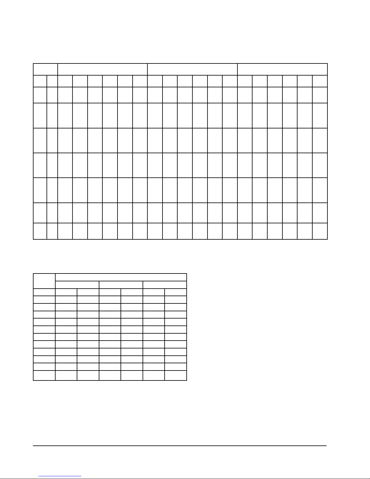
PERFORMANCE AND APPLICATION DATA – ERV-F*2
Summer Cooling Performance
(Indoor Design Conditions 75°DB/62°WB)
Ambient
OD
DB/
F VLT VLS VLL HRT HRS HRL V LT VLS VLL HRT HRS HRL V LT VLS VLL HRT HRS HRL
WB
1057570
100
95
90
85
80
757065
11925
8100
65
8100
80
17550
75
11925
70
6863
65
6750
60
6750
80
17550
75
11925
70
6863
65
5400
60
5400
80
17550
75
11925
70
6863
65
4050
60
4050
80
17550
75
11925
70
6683
65
2700
60
2700
75
11925
70
6863
65
2363
60
1350
6863
2363
60
Ventilation Rate 250 CFM
8100
8100
8100
6750
6750
6750
6750
6750
5400
5400
5400
5400
5400
4050
4050
4050
4050
4050
2700
2700
2700
2700
2700
1350
1350
1350
1350
0
0
0
0
62% Efficiency
1325
79394
0
5022
0
5022
10800
10881
5175
7394
113
4255
0
4185
0
4185
12150
10881
6525
7394
1463
4255
0
3348
0
3348
13500
10881
7875
7394
2813
4255
0
2511
0
2511
14850
10881
9225
7394
4163
4255
0
1674
0
1674
10575
7394
5513
4255
1013
1465
0
837
6863
4255
2363
1465
0
Ventilation Rate 225 CFM
63% Efficiency
2168
822
10727
7287
3441
6758
5022
5022
5022
4185
4185
4185
4185
4185
3348
3348
3348
3348
3348
2511
2511
2511
2511
2511
1674
1674
1674
1674
1674
0
837
837
837
837
0
7287
7287
15788
10727
6173
6072
6072
15788
10727
6173
4858
4858
15788
10727
6173
3643
3643
15788
10727
6173
2429
2429
10727
6173
2125
1214
6173
2125
0
7287
7287
6072
6072
6072
6072
6072
4858
4858
4858
4858
4858
3643
3643
3643
3643
3643
2429
2429
2429
2429
2429
1214
1214
1214
1214
0
6696
3209
70
0
0
7533
4046
907
0
0
8370
4883
1744
0
0
9207
5720
2581
0
0
6557
3418
628
0
4255
0
1465
0
0
0
0
0
9716
4655
101
0
0
10930
5870
1315
0
0
12145
7084
2530
0
0
13359
8298
3744
0
0
9513
4959
911
0
0
6173
0
2125
0
0
4591
4591
9946
6758
3889
3826
3826
9946
6758
3889
3060
3060
9946
6758
3889
2295
2295
9946
6758
3889
1530
1530
6758
3889
1339
765
6889
1339
0
4591
4591
4591
3826
3826
3826
3826
3826
3060
3060
3060
3060
3060
2295
2295
2295
2295
2295
1530
1530
1530
1530
1530
765
765
765
765
0
0
0
0
0
6121
2933
64
0
0
6886
3698
829
0
0
7651
4463
1594
0
0
8416
5228
2359
0
0
5993
3124
574
0
6889
1339
0
9540
6480
6480
14040
9540
5490
5400
5400
14040
9540
5490
4320
4320
14040
9540
5490
3240
3240
14040
9540
5490
2160
2160
9540
5490
1890
1080
5490
1890
Ventilation Rate 200 CFM
6480
6480
6480
5400
5400
5400
5400
5400
4320
4320
4320
4320
4320
3240
3240
3240
3240
3240
2160
2160
2160
2160
2160
1080
1080
1080
1080
0
0
0
0
63% Efficiency
3060
6010
0
4082
0
4082
8640
8845
4140
6010
90
3458
0
3402
0
3402
9720
8845
5220
6010
1170
3458
0
2722
0
2722
10800
8845
6300
6010
2250
3458
0
2041
0
2041
11880
8845
7380
6010
3300
3458
0
1361
1361
0
8460
6010
4410
3458
810
1190
0
680
5490
3458
1890
1190
0
0
4082
4082
4082
3402
3402
3402
3402
3402
2722
2722
2722
2722
2722
2041
2041
2041
2041
2041
1361
1361
1361
1361
1361
680
680
680
680
0
0
0
1928
0
0
5443
2608
56
0
0
6124
3289
737
0
0
6804
3969
1417
0
0
7484
4649
2098
0
0
5330
2778
510
0
3458
1190
0
Winter Heating Performance
(Indoor Design Conditions 70°F DB)
Ambient
OD
DB/°F WVL WHR WVL WHR WVL WHR
65 1350 999 1214 911 1080 810
60 2700 1998 2429 1822 2160 1620
55 4050 2997 3643 2733 3240 2430
50 5400 3996 4858 3643 4320 3240
45 6750 4995 6072 4554 5400 4050
40 8100 5994 7287 5465 6480 4860
35 9450 6993 8501 6376 7560 5670
30 10800 7992 9716 7287 8640 6480
25 12150 8991 10930 8198 9720 7290
20 13500 9990 12145 9108 10800 8100
15 14850 10989 13359 10019 11880 8910
250 CFM 74% Eff. 225 CFM 75% Eff. 200 CFM 75% Eff.
Ventilation Rate
LEGEND:
VLT = Ventilation Load – Total
VLS = Ventilation Load – Sensible
VLL = Ventilation Load – Latent
HRT = Heat Recovery – Total
HRS = Heat Recovery – Sensible
HRL = Heat Recovery – Latent
WVL = Winter Ventilation Load
WHR = Winter Heat Recovery
NOTE: All performance data is based on
operating intake and exhaust blower on
the same speed.
Manual 2100-701
Page 4 of 16
Page 5
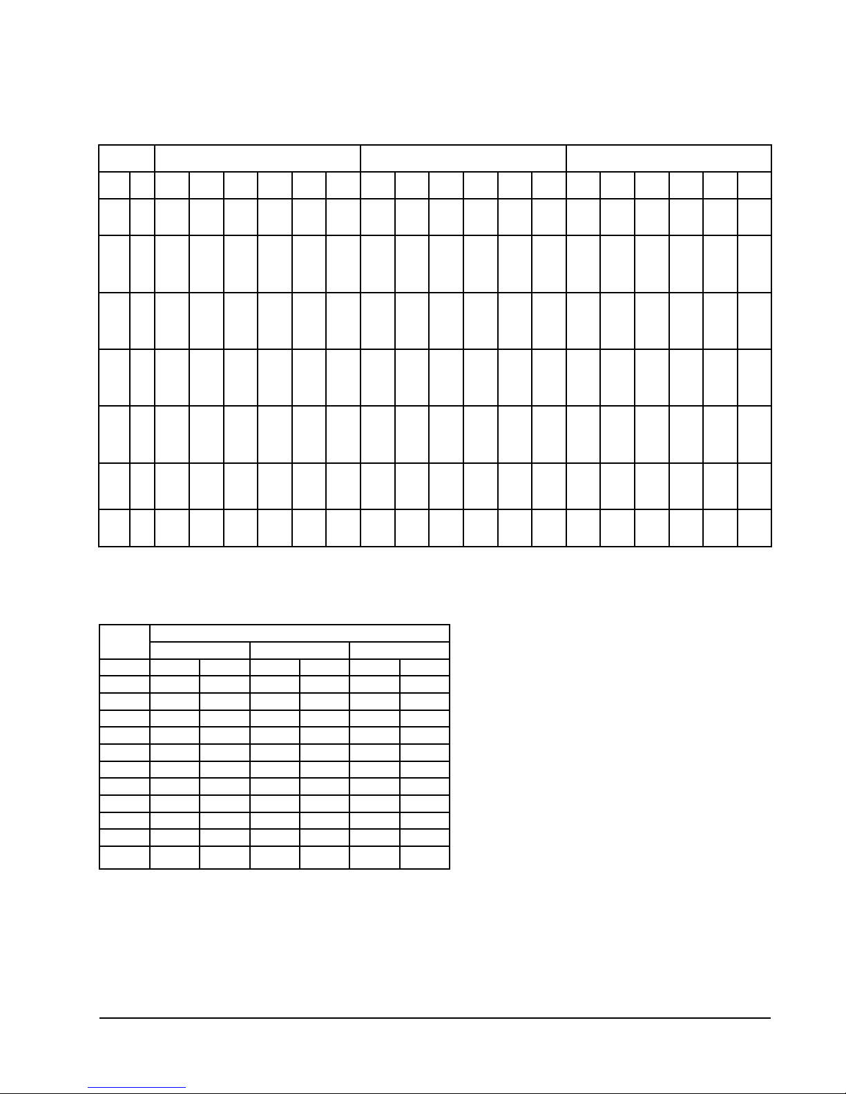
PERFORMANCE AND APPLICATION DATA – ERV-F*3
Summer Cooling Performance
(Indoor Design Conditions 75°DB/62°WB)
Ambient
OD
DB/
F VLT VLS VLL HRT HRS HRL V LT VLS VLL HRT HRS HRL V LT VLS VLL HRT HRS HRL
WB
1057570
100
95
90
85
80
757065
19080
12960
65
12960
80
29080
75
19080
70
10980
65
10800
60
10800
80
28080
75
19080
70
10980
65
8640
60
8640
80
28080
75
19080
70
10980
65
6480
60
6480
80
28080
75
19080
70
10980
65
4320
60
4320
75
19080
70
10980
65
3780
60
2160
10980
3780
60
Ventilation Rate 400 CFM
12960
12960
12960
10800
10800
10800
10800
10800
8640
8640
8640
8640
8640
6480
6480
6480
6480
6480
4320
4320
4320
4320
4320
2160
2160
2160
2160
0
0
0
0
63% Efficiency
6120
12020
0
8164
0
8164
17280
17690
8280
12020
180
6717
0
6804
0
6804
19440
17690
10440
12020
2340
6917
0
5443
0
5443
21600
17690
12600
12020
4500
6917
0
4082
0
4082
23760
17690
14760
12020
6660
6917
0
2721
0
2721
16920
12020
8820
6917
1620
2381
0
1360
10980
6917
3780
2381
0
Ventilation Rate 325 CFM
64% Efficiency
3182
3855
15502
10530
4972
9921
8164
8164
8164
6804
6804
6804
6804
6804
5443
5443
5443
5443
5443
4082
4082
4082
4082
4082
2721
2721
2721
2721
2721
1360
1360
1360
1360
0
0
10530
10530
22815
15502
8921
8775
8775
22815
15502
8921
7020
7020
22815
15502
8921
5265
5265
22815
15502
8921
3510
3510
15502
8921
3071
1755
8921
3071
0
10530
10530
8775
8775
8775
8775
8775
7020
7020
7020
7020
7020
5265
5265
5265
5265
5265
3510
3510
3510
3510
3510
1755
1755
1755
1755
0
10886
5216
113
0
0
12247
6577
1474
0
0
13608
7938
2835
0
0
14968
9298
4195
0
0
10659
5556
1020
0
6917
0
2380
0
0
0
0
0
14040
6727
146
0
0
15795
8482
1901
0
0
17550
10237
3656
0
0
19305
11992
5411
0
0
13747
7166
1316
0
0
8921
0
3071
0
0
6739
6739
14601
9921
5709
5616
5616
14601
9921
5709
4492
4492
14601
9921
5709
3369
3369
14601
9921
5709
2246
2246
9921
5709
1965
1123
5709
1965
0
6739
6739
6739
5616
5616
5616
5616
5616
4492
4492
4492
4492
4492
3369
3369
3369
3369
3369
2246
2246
2246
2246
2246
1123
1123
1123
1123
0
0
0
0
0
8985
4305
93
0
0
10108
5428
1216
0
0
11232
6552
2340
0
0
12355
7675
3463
0
0
8798
4586
842
0
5709
1965
0
11925
8100
8100
17550
11925
6862
6750
6750
17550
11925
6862
5400
5400
17550
11925
6862
4050
4050
17550
11925
6862
2700
2700
11925
6862
2362
1350
6862
2362
Ventilation Rate 250 CFM
8100
8100
8100
6750
6750
6750
6750
6750
5400
5400
5400
5400
5400
4050
4050
4050
4050
4050
2700
2700
2700
2700
2700
1350
1350
1350
1350
0
0
0
0
65% Efficiency
3825
7751
0
5265
0
5265
10800
11407
5175
7751
112
4460
0
4387
0
4387
12150
11407
6525
7751
1462
4460
0
3510
0
3510
13500
11407
7875
7751
2812
4460
0
2632
0
2632
14850
11407
9225
7751
4162
4460
0
1755
1755
0
10575
7751
5512
4460
1012
1535
0
877
6862
4460
2362
1535
0
0
5265
5265
5265
4387
4387
4387
4387
4387
3510
3510
3510
3510
3510
2632
2632
2632
2632
2632
1755
1755
1755
1755
1755
877
877
877
877
0
0
0
2486
0
0
7019
3363
73
0
0
7897
4241
950
0
0
8774
5118
1828
0
0
9652
5996
2705
0
0
6873
3583
658
0
4460
1535
0
Winter Heating Performance
(Indoor Design Conditions 70°F DB)
Ambient
OD
DB/°F WVL WHR WVL WHR WVL WHR
65 2160 1620 1755 1333 1350 1039
60 4320 3240 3510 2667 2700 2079
55 6480 4860 5265 4001 4050 3118
50 8640 6480 7020 5335 5400 4158
45 10800 8100 8775 6669 6750 5197
40 12960 9720 10530 8002 8100 6237
35 15120 11340 12285 9336 9450 7276
30 17280 12960 14040 10670 10800 8316
25 19440 14580 15795 12004 12150 9355
20 21600 16200 17550 13338 13500 10395
15 23760 17820 19305 14671 14850 11434
400 CFM 75% Eff. 325 CFM 76% Eff. 250 CFM 77% Eff.
Ventilation Rate
LEGEND:
VLT = Ventilation Load – Total
VLS = Ventilation Load – Sensible
VLL = Ventilation Load – Latent
HRT = Heat Recovery – Total
HRS = Heat Recovery – Sensible
HRL = Heat Recovery – Latent
WVL = Winter Ventilation Load
WHR = Winter Heat Recovery
NOTE: All performance data is based on
operating intake and exhaust blower on
the same speed.
Manual 2100-701
Page 5 of 16
Page 6

BASIC FIELD INSTALLATION
1. Unpack the ventilator assembly which includes the
integral ventilator with attached electrical harness
and miscellaneous hardware.
!
WARNING
Open and lock unit disconnect switch
before installing this accessory to prevent
injury or death due to electrical shock or
contact with moving parts. Turn thermostat
to OFF.
2. Disconnect unit power.
3. Remove the existing exterior blower access, filter
access and vent option panels on the wall mount
unit (see Figure 1). Save the blower access and
filter access panels and discard the vent option
panel.
FIGURE 1
Remove Access Panels
TABLE 1
Model Reference
Model
ERV-FA2
ERV-FC2 W24AB-C W24HB-C
ERV-FA3
ERV-FC3
!
Be sure the correct model and voltage
energy recovery ventilator is used with
the correct air conditioner or heat pump to
ensure correct voltage compatibility.
For Use with the
Following Units
W18AB-A
W24AB-A, -B
W30AB-A, -B
W36AB-A, -B
W30AB-C
W36AB-C
W18HB-A
W24HB-A, -B
W30HB-A, -B
W36HB-A, -B
W30HB-C
W36HB-C
CAUTION
Electrical
230/208V
1 or 3 phase
460V
3 phase
230/208V
1 or 3 phase
460ERV-F
3 phase
FILTER ACCESS PANEL
BLOWER ACCESS
PANEL
VENT OPTION PANEL
Manual 2100-701
Page 6 of 16
Page 7

4. Remove and save existing unit return air filter.
Remove left side filter support bracket by
unscrewing two (2) screws from left side of unit.
Remove and save top four (4) screws from front
grille (see Figure 2).
5. Remove and discard exhaust cover plate (see
Figure 2).
Remove Filter, Filter Support Bracket and Exhaust Cover Plate
FILTER FILL
LEFT FILTER
BRACKET
FILTER
FIGURE 2
REMOVE & DISCARD
EXHAUST COVER PLATE
(4) SCREWS
HOLDING FRONT GRILLE
MIS-4003
Manual 2100-701
Page 7 of 16
Page 8

6. Insert ventilator into the unit to the far left side,
making sure to clear the right filter bracket. Once
the ventilator is fully inserted, slide the ventilator
to the right until it is tight against the back of the
control panel (see Figure 3).
IMPORTANT NOTE: Position front lip of ventilator
over front grille and on top of condenser partition
(see Figure 3 inset). This is important to ensure
proper drainage of any water entering damper
assembly.
Install Ventilator
7. Remove outer and inner control panel covers.
8. Remove female plug of high voltage wiring harness
(3-pin plug) from the heat recovery assembly
and snap into unit control panel (from inside
control panel) in the hole provided. Wire to top of
compressor contactor per wiring diagram (on ERV).
Connect high voltage plugs back together (see
Figure 3).
FIGURE 3
CAUTION: HOLE IN ERV-F MUST
CAUTION: HOLE IN ERV-F MUST
BE USED TO ENSURE CLEARANCE
BE USED TO INSURE CLEARANCE
FROM CONDENSER COIL TUBING
FROM CONDENSER COIL TUBING
SERVICE DOOR
FIGURE 3 (INSET)
LIP OF ERV IS TO BE
BETWEEN THE CONDENSER
GRILL AND SERVICE DOOR
FRONT GRILLE
HIGH & LOW VOLTAGE
TO PLUG IN SIDE OF
CONTROL PANEL
WHEN INSTALLING ERV-F POSITION
SO THAT HOLE IN FROM LIP IS
CENTERED OVER HOLE IN CONDENSER
GRILLE TO INSERT A SELF DRILLING
SCREW
HEAT RECOVERY
VENTILATOR
CONDENSER
PARTITION
SIDE SECTION VIEW
MIS-4004
Manual 2100-701
Page 8 of 16
Page 9

9. Plug low voltage plug (12-pin plug) from the heat
recovery unit into the front side of the control
panel (see Figures 3 and 4).
NOTE: These 24 volt control wires control the starting
and stopping of the energy recovery ventilator
and can be independently controlled by an
energy management control or timer. See
Control Wiring on page 11.
FIGURE 4
Install Low and High Voltage Plugs and Wiring
11. Replace inner and outer control panel covers.
12. Ventilator checkout
A. Resupply power to unit.
B. Energize the “A” occupancy 24 volt signal on
the low voltage terminal strip (jumper “R” to
“A”).
INSTALL INCLUDED HIGH
VOLTAGE 3-PIN PLUG INTO
SIDE OF CONTROL PANEL,
THEN ROUTE THE WIRES AS
SHOWN, AND WIRE PER WIRE
DIAGRAM.
WIRE DIAGRAM
PROVIDED ON ERV
LOW VOLTAGE 12 PIN PLUG
FROM ERV ASSEMBLY
GROUND WIRE
HIGH VOLTAGE WIRES
MIS-3776
MIS-3776
Manual 2100-701
Page 9 of 16
Page 10

C. Ventilator heat transfer wheels should rotate
slowly (49 RPM). Intake and exhaust blowers
should run and indoor comfort blower should
run.
D. De-energize the “A” terminal. The energy
recovery wheels, fresh air, exhaust air and
indoor comfort blowers should stop.
E. This completes ventilator checkout.
13.
Re-install the blower access and filter access panels
at top of unit and secure with sheet metal screws.
Install Fresh Air Intake Hood Assembly
INSERT FLANGE THRU SLOT IN DOOR AND
PUSH FLANGE UNDER INSULATION
INSULATION
FILTER
ACCESS
PANEL
14.
15. Apply Certification label, included with installation
16. Ventilator is now ready for operation.
FIGURE 5
Replace the vent option access panel with the new
panel provided. Attach air intake hood with screws
provided (see Figure 5). Be sure to insert the top
flange of the air intake hood into and through the
slot of the service door and between the door and
insulation to prevent bowing of the door.
instructions, next to unit serial plate.
FRESH AIR INTAKE
HOOD AND FILTER
ASSEMBLY
FILTER ACCESS
SCREW
REPLACE SERVICE ACCESS PANEL AND
INSTALL FRESH AIR INTAKE HOOD
ASSEMBLY AS SHOWN
Manual 2100-701
Page 10 of 16
Page 11

CONTROL WIRING
The ERV-F comes from the factory with the low voltage
control wires connected to the wall mount low voltage
terminal strip. Care must be taken when deciding
how to control the operation of the ventilator. When
designing the control circuit for the ventilator, the
following requirements must be met.
Control Requirements
1. Indoor blower motor will automatically run
whenever the ERV-F is run.
2. Select the correct motor speed tap in the ERV-F.
Using Table 2, determine the motor speed needed
to get the desired amount of ventilation air
needed. For instance, do not use the high speed
tap on a ERV-F*3 if only 250 CFM of ventilation
air is needed. Use the low speed tap instead (see
VENTILATION AIRFLOW for information on
moving the speed taps). Using the high speed tap
would serve no useful purpose and significantly
affect the overall efficiency of the air conditioning
system. System operating cost would also increase.
TABLE 2
Ventilation Air (CFM)
Model
ERV-FA2
ERV-FC2
ERV-FA3
ERV-FC3
3. Run the ERV-F only during periods when the
conditioned space is occupied. Running the
ERV-F during unoccupied periods wastes energy,
decreases the expected life of the ERV-F and can
result in a large moisture buildup in the structure.
The ERV-F removes 60-70% of the moisture in the
incoming air, not 100% of it. Running the ERV-F
when the structure is unoccupied allows moisture
to build up in the structure because there is little
or no cooling load. Thus, the air conditioner is not
running enough to remove the excess moisture
being brought in. Use a control system that
in some way can control the system based on
occupancy.
!
High Speed
(Black)
250 225 200
400 325 250
IMPORTANT
Medium Speed
(Blue)
Low Speed
(Red)
Recommended Control Sequences
Several possible control scenarios are listed below:
1. Use a programmable electronic thermostat with
auxiliary terminal to control the ERV-F based
on daily programmed occupancy periods. Bard
markets and recommends Bard Part No. 8403060 programmable electronic thermostat for air
conditioner and heat pump applications.
2. Use a motion sensor in conjunction with a
mechanical thermostat to determine occupancy
in the structure. Bard recommends Bard Model
CS9B*-**** CompleteStat for this application.
3. Use a CO
ERV-F when CO
4. Use a DDC control system to control the ERV-F
based on a room occupancy schedule to control
the ERV-F.
5. Tie the operation of the ERV-F into the light switch.
The lights in a room are usually on only when
occupied.
6.
Use a manual timer that the occupants turn to
energize the
7. Use a programmable mechanical timer to energize
the ERV-F and indoor blower during occupied
periods of the day.
control with dry contacts to energize the
2
levels rise above desired settings.
2
ERV-F
for a specific number of hours.
VENTILATION AIRFLOW
The ERV-FA* and ERV-FC* are equipped with a
3-speed motor to provide the capability of adjusting
the ventilation rates to the requirements of the specific
application by changing motor speeds (see Table 2).
!
WARNING
Open disconnect to shut all power OFF
before changing motor speeds. Failure to
do so could result in injury or death due to
electrical shock.
The units are set from the factory with the exhaust
blower on the low speed and the intake blower on
medium speed. Moving the speed taps located in the
control panel can change the blower speed of the
intake and exhaust (see Figure 6 on page 12).
Operating the ERV-F during unoccupied
periods can result in a buildup of moisture
in the structure.
Manual 2100-701
Page 11 of 16
Page 12

FIGURE 6
Speed Tap Label
Manual 2100-701
Page 12 of 16
Page 13

FIGURE 7
Airflow Diagram
Manual 2100-701
Page 13 of 16
Page 14

ENERGY RECOVERY VENTILATOR
MAINTENANCE
General Information
The ability to clean exposed surfaces within air moving
systems is an important design consideration for the
maintenance of system performance and air quality.
The need for periodic cleaning will be a function of
operating schedule, climate and contaminants in the
indoor air being exhausted and in the outdoor air being
supplied to the building. All components exposed to
the airstream, including energy recovery wheels, may
require cleaning in most applications.
Rotary counterflow heat exchanges (heat wheels) with
laminar airflow are “self-cleaning” with respect to
dry particles. Smaller particles pass through; larger
particles land on the surface and are blown clear
as the flow direction is reversed. For this reason,
the primary need for cleaning is to remove films of
oil-based aerosols that have condensed on energy
transfer surfaces. Buildup of material over time may
eventually reduce airflow. Most importantly, in the
case of desiccant-coated (enthalpy) wheels, such films
can close off micron-sized pores at the surface of the
desiccant material, reducing the efficiency with which
the desiccant can absorb and desorb moisture.
water molecules. The continued ability of an enthalpy
wheel to transfer latent energy depends upon the
permanence of the bond between the desiccant and
the energy transfer surfaces.
Bard wheels feature silica gel desiccant permanently
bonded to the heat exchange surface without
adhesives; the desiccant will not be lost in the washing
process. Proper cleaning of the Bard energy recovery
wheel will restore latent effectiveness to near original
performance.
Maintenance Procedures
NOTE: Local conditions can vary and affect the
required time between routine maintenance
procedures; therefore, all sites (or specific
units at a site) may not have the same
schedule to maintain acceptable performance.
The following timetables are recommended and
can be altered based on local experience.
Quarterly Maintenance
1. Inspect mist eliminator/prefilter and clean if
necessary. This filter is located in the fresh air
intake hood on the front of the unit. This is an
aluminum mesh filter and can be cleaned with
water and any detergent not harmful to aluminum.
Frequency
In a reasonably clean indoor environment such as a
school, office building or home, experience shows that
reductions of airflow or loss of sensible (temperature)
effectiveness may not occur for 10 or more years.
However, experience also shows that measurable
changes in latent energy (water vapor) transfer can
occur in shorter periods of time in commercial,
institutional and residential applications experiencing
moderate occupant smoking or with cooking facilities.
In applications experiencing unusually high levels
of occupant smoking, such as smoking lounges,
nightclubs, bars and restaurants, washing of energy
transfer surfaces, as frequently as every 6 months,
may be necessary to maintain latent transfer efficiency.
Similar washing cycles may also be appropriate for
industrial applications involving the ventilation of high
levels of smoke or oil-based aerosols such as those
found in welding or machining operations, for example.
In these applications, latent efficiency losses of as
much as 40% or more may develop over a period of 1
to 3 years.
Cleanability and Performance
In order to maintain energy recovery ventilation
systems, energy transfer surfaces must be accessible
for washing to remove oils, grease, tars and dirt that
can impede performance or generate odors. Washing
of the desiccant surfaces is required to remove
contaminate buildups that can reduce absorption of
2. Inspect wall mount unit filter and clean or replace
as necessary. This filter is located either in the
unit, in a return air filter grille assembly or both.
If in the unit it can be accessed by removing the
lower service door on the front of the unit. If in a
return air filter grille, by hinging the grille open to
gain access.
3. Inspect energy recovery ventilator for proper wheel
rotation and dirt buildup. This can be done in
conjunction with Item 2 above. Energize the energy
recovery ventilator after inspecting the filter and
observe for proper rotation and/or dirt buildup.
4. Recommended energy recovery wheel cleaning
procedures follow: Disconnect all power to
unit. Remove the lower service door of the wall
mount unit to gain access to the energy recovery
ventilator.
5. Remove the front access panel on the ventilator.
Unplug amp connectors to cassette motors. Slide
energy recovery cassette out of ventilator.
6. Use a shop vacuum with brush attachment to clean
both sides of the energy recovery wheels.
7. Reverse shop vacuum to use as a blower and blow
out any residual dry debris from the wheel.
NOTE: Discoloration and staining of the wheel does
not affect its performance. Only excessive
buildup of foreign material needs to be
removed.
Manual 2100-701
Page 14 of 16
Page 15

8. If any belt chirping or squealing noise is present,
Belt Replacement
Instructions
MIS-1890
Route this part of replacement
belt in bottom groove of pulley.
Route this part of replacement
belt in top groove of pulley.
If belt "squeaks" or "chirps"
lubricate lightly with LPS-1
or equivalent "dry film"
lubricant.
apply a small amount of LPS-1 or equivalent dry
film lubricant to the belt.
3. Rinse wheel thoroughly after application of the
cleaning solution and allow to drain before reinstalling.
Annual Maintenance
1. Inspect and conduct the same procedures as
outlined under Quarterly Maintenance.
2. To maintain peak latent (moisture) removal
capacity, it is recommended that the energy
recovery wheels be sprayed with a diluted nonacidbased evaporator coil cleaner or alkaline detergent
solution such as 409.
NOTE: Do not use acid-based cleaners, aromatic
solvents, temperatures in excess of 170°F or
steam. Damage to the wheel may result.
Do not disassemble and immerse the entire
heat wheel in a soaking solution, as bearing
and other damage may result.
Belt Replacement Instructions
(Two Wheel Cassette Only)
4. No re-lubrication is required to heat wheel bearings
of the drive motor, or to the intake and exhaust
blower motors.
5. If any belt chirping or squealing noise is present,
apply a small amount of LPS-1 or equivalent dry
film lubricant to the belt.
Figure 8
Manual 2100-701
Page 15 of 16
Page 16

FIGURE 9
Hub Assembly with Ball Bearings
Manual 2100-701
Page 16 of 16
 Loading...