

Bard EHWH42-A15, EHWA05-A05, EHWA05-A15, EHWH42-C06, EHWA05-A20 Installation Instructions Manual
...Page 1

INSTALLATION INSTRUCTIONS
ELECTRIC HEAT PACKAGES
Models
:
EHWH42-A05 EHWA05-A05
EHWH42-A10 EHWA05-A10
EHWH42-A15 EHWA05-A15
EHWH42-C06 EHWA05-A20
EHWH04-A04 EHWA05-B09
EHWH04-A05 EHWA05-B15
EHWH04-A10 EHWA05-B18
EHWH04-A15 EHWA05A-C09
EHWH04-A20 EHWA05A-C15
EHWH04-B18 EHWA60-A05
EHWH05-B09 EHWA60-B09
EHWH05-B15 EHW05A-B18
EHWH05A-C09 EHW05H-B18
EHWH05A-C15 EHW60A-B09
EHWH05-B06 EHW70A-B09
EHW70A-B18
FOR WITH WA, SH AND WH SERIES
WALL MOUNTED AIR CONDITIONERS
AND HEAT PUMPS
(SEE TABLES 1A — 1F FOR MODEL USAGE)
Bard Manufacturing Company, Inc.
Bryan, Ohio 43506
Since 1914...Moving ahead, just as planned.
Manual: 2100-254E
Supersedes: 2100-254D
File: Volume III, Tab 18
Date: 10-21-10
Manual 2100-254E
Page 1 of 17
Page 2

CONTENTS
General Information
Description of Equipment.................................. 3
Nomenclature ................................................... 3
Important ........................................................... 8
Shipping Damage ............................................. 8
Unpacking Electric Heat Package .................... 8
Wiring Main Power ............................................ 8
Installation
Installation of Heater Package ........................ 10
Tables
Table 1A
Table 1B
Table 1C
Table 1D
Table 1E
Table 1F
Table 2 Electrical Data and BTU Output ......... 7
Table 3 Terminal and Screw Mounting .......... 12
Figures
Figure 1 Electrical Connections ...................... 9
Figure 2 Installation of Heater Package ........ 11
Figure 3 Rod Support & Screw Mounting ..... 13
Figure 4A - 4D Terminal Identification ........... 14
Figure 4E - 4F Terminal Identification........... 15
Figure 5 Wiring Directions ............................. 16
Figure 6 Marking Serial Plate ........................ 17
Heater Usage by Model Matrix .......... 3
Heater Usage by Model Matrix .......... 4
Heater Usage by Model Matrix .......... 4
Heater Usage by Model Matrix .......... 5
Heater Usage by Model Matrix .......... 6
Heater Usage by Model Matrix .......... 6
Manual 2100-254E
Page 2 of 17
Page 3
GENERAL INFORMATION
DESCRIPTION OF EQUIPMENT
The EHWA and EHWH series electric heater packages
are field installable heater packages suitable for use with
Bard wall mount hi boy air conditioners and heat
pumps. The packages consist of the electric heat strip,
the heater control base which includes the heat
contactors, and circuit breaker or pull disconnects,
installation instructions and wiring diagrams. See Table
1 for nominal electrical data and BTU output. Before
installation, check unit serial plate to insure the heater
package model that you intend to install is listed as a
heater package that is suitable for use with the Bard wall
mount hi boy unit. See Figure 6.
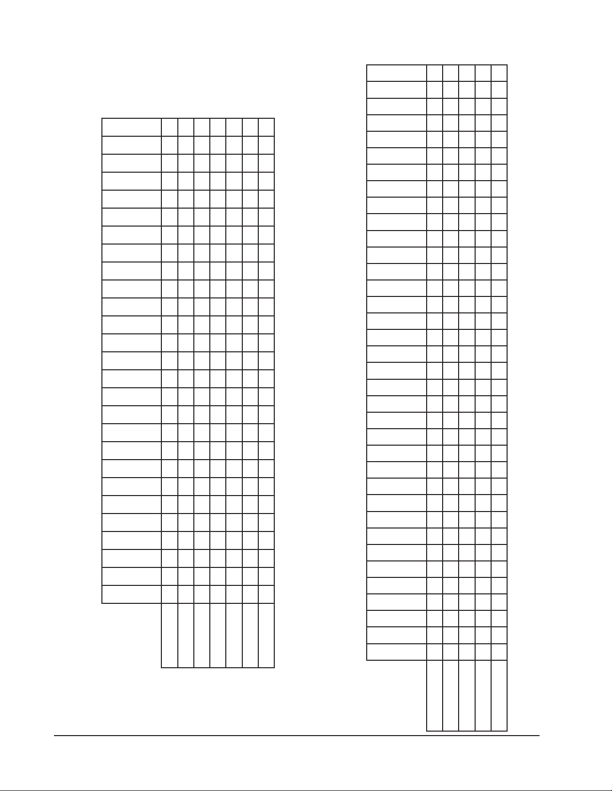
TABLE 1A
R-22 HEATER USAGE BY MODEL MATRIX
V802/032
esahP1
WA423-A
WA424DA
WA484-A
WA484DA
WA484HA
WA6023A
WA602-A
50A-50AWHE XXXX X
01A-50AWHE XXXX XX XXX X X
51A-50AWHEXXXX
02A-50AWHEXXXX
50A-06AWHEX
40A-40HWHE X
50A-40HWHE XX
01A-40HWHEXXXXX
51A-40HWHE X
02A-40HWHE XX
50A-24HWHE XXXX
01A-24HWHE XXXX
51A-24HWHE XX
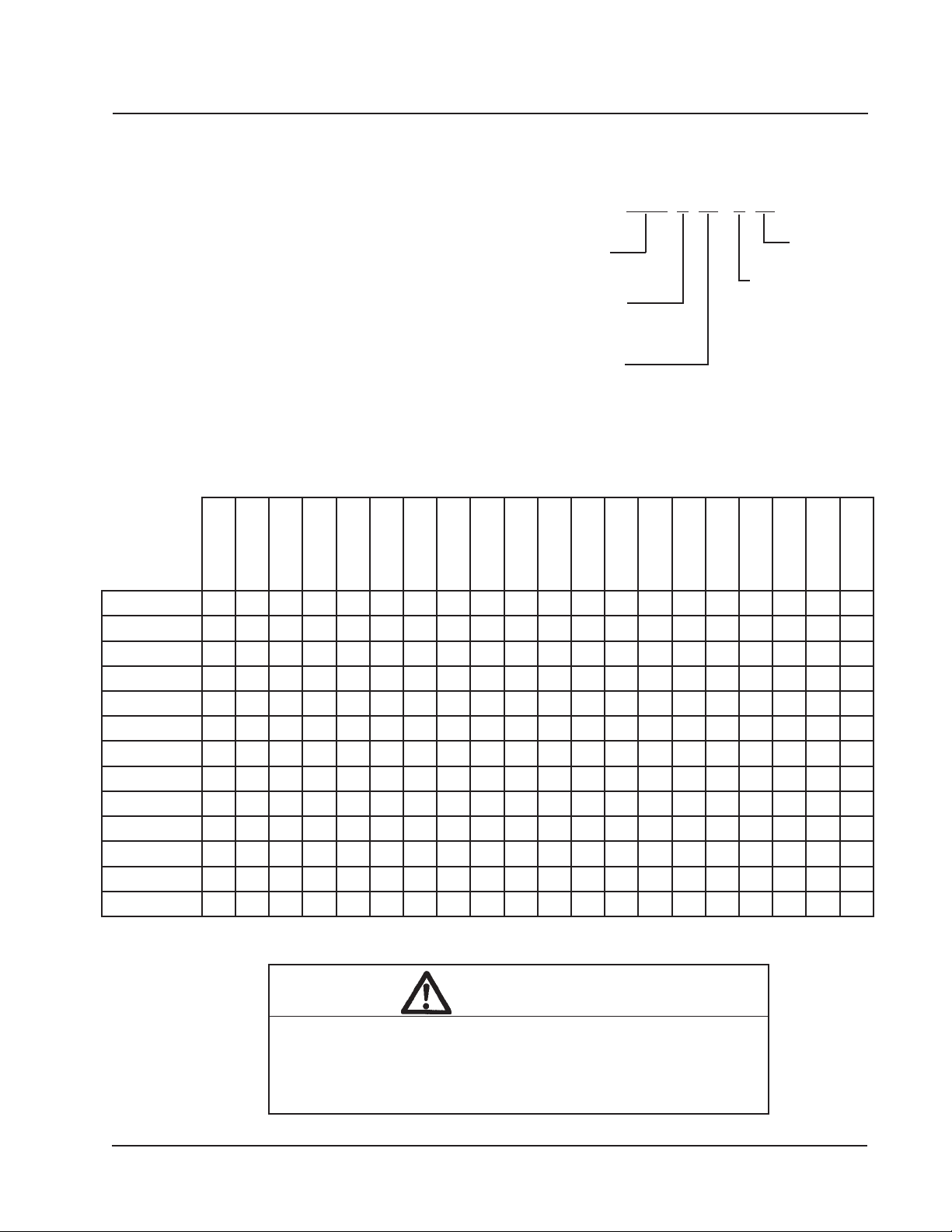
NOMENCLATURE
ELECTRIC HEATER
PACKAGE
WALL MOUNT
A = AIR CONDITIONER
H = HEAT PUMP
C = AIR CONDITIONER
and HEAT PUMP
SUITABLE FOR USE IN
SEE TABLES 1A — 1F
WA602HA
WA603DA
WA7023A
EHW A 04 - A 05
WA702-A
WA702HA
WH421-A
WH421DA
WH483-A
WH483DA
NOMINAL KW
5 KW
ELECTRICAL VERSION
A - 240/208V - 1Ph
B - 240/208V - 3Ph
C - 460V - 3PH
WH483LA
WH602-2
WH602DA
WH602LA
WARNING
Only use factory provided heaters in approved combinations of
heater models to unit models as shown in tables 1A — 1F. Failure
to use approved combinations as shown or modification to heaters
could result in fire causing damage, bodily injury or death.
Manual 2100-254E
Page 3 of 17
Page 4
WH602LB
WH602DB
WH602-B
WH483LB
WH483DB
WH483-B
WH421LB
WH421DB
WH421-B
WA721-B
WA701HB
WA701-B
WA7013B
WA603DB
WA602TB
WA602HB
WH602-E
TABLE 1B
WA602-B
WA6023B
WA484TB
WA484HB
R-22 HEATER USAGE BY MODEL MATRIX
WA484-E
WA484DB
WA484-B
WA423-E
WA423DB
WA423-B
90B-50HWHE X X X XX XX XX
90B-50AWHE XXXXXX X X X X X
51B-50AWHE XXXX XX XXX
V8028032
V022/042
esahP3
81B-50AWHE XXXX X XXX
81B-40HWHE XX
90B-06AWHE XX XXXX X
WH602LC
WH602DC
WH602-C
WH483LC
WH483DC
WH483-C
WH421LC
WH421DC
WH421-C
WH381DC
WE701-F
WE602-F
WE482-F
WE421-F
WA721-C
WA701HC
WA101-F
WA701-C
WA611-C
WA603DC
WA602HC
TABLE 1C
WA602-F
WA602-C
WA491-C
WA484HC
WA484-F
R-22 HEATER USAGE BY MODEL MATRIX
WA484DC
WA484-C
WA423-F
WA423DC
WA423-C
WA381-C
SH611-C
51B-50HWHE XXX
SH491-C
SH431-C
SH381-C
Manual 2100-254E
Page 4 of 17
90C-A50HWHE XXXX XXXXXXXXX
90C-A50AWHE XXXXXXX XXXXXXXXXXXXXX
51C-A50AWHE X X XXX XXX
esahP3
V064
V414
51C-A50HWHE XXX
60C-24HWHE XXX XXX
Page 5

TABLE 1D
R-410A HEATER USAGE BY MODEL MATRIX
V802/032
esahP1
W42A1-A
W42A1DA
W48A1-A
W48A1DA
W60A1-A
W60A1DA
W60A13A
W70A1-A
W42H1-A
W42H1DA
W48H1-A
W48H1DA
W60H1-A
W60H1DA
W5RV1-R
50A-50AWHE XXXX X
01A-50AWHE XXXXXXXX
51A-50AWHE XXX X
02A-50AWHE XXX X
02AH50AWHE X
40A-40HWHEXX
50A-40HWHE XX
01A-40HWHE XXX
51A-40HWHE X
02A-40HWHEX
50A-24HWHE XXXX
01A-24HWHE XXXX
51A-24HWHEXX
50A-06AWHEXX
X
Manual 2100-254E
Page 5 of 17
Page 6

TABLE 1E
R-410 AHEATER USAGE BY MODEL MATRIX
V022/042
V8028032
esahP3
W42A1-B
W42A1DB
W42A1-E
W48A1-B
W48A1DB
W48A1-E
W60A1-B
W60A1DB
W60A1-E
W70A1-B
W42H1-B
W42H1DB
W48H1-B
W48H1DB
W60H1-B
W60H1DB
W5RV1-S
W6RV1-S
81B-A50WHE XXXXXX
81B-H50WHEXX
90B-A06WHEX
90B-A07WHEX
90BHA07WHE X
81B-A07WHEXX
81BHA07WHE X
90B-50AWHE
XXXXXX X
51B-50AWHE X XX XXX X
81B-50AWHEX
90B-06AWHEX
60B-50HWHE XXXX
90B-50HWHE XXXXXXX
51B-50HWHE XXX
TABLE 1F
R-410A HEATER USAGE BY MODEL MATRIX
V414
V064
esahP3
W42A1-C
W42A1DC
W42A1-F
W48A1-C
W48A1DC
W48A1-F
W60A1-C
W60A1DC
W60A1-F
W70A1-C
W70A1-P
W42H1-C
W42H1DC
W48H1-C
W48H1DC
W60H1-C
W60H1DC
W5RV1-T
W6RV1-T
90C-A50AWHE XXXXXXXXXXX
51C-A50AWHE XXXX
41F-A50AWHE XXXX
90C-A50HWHE XXXXXXXX
51C-A50HWHE XXXXX
60C-24HWHEXXX
Manual 2100-254E
Page 6 of 17
Page 7

TABLE 2
ELECTRICAL DATA AND BTU OUTPUT
ledoMegakcaPretaeHstloVesahPWKlanimoNUTBlanimoN
50A-50AWHE802/0421/557.3/560,71008,21
01A-50AWHE802/0421/015.7/031,43006,52
51A-50AWHE802/0421
02A-50AWHE802/0421/0251/062,86002,15
90B-50AWHE802/0423/957.6/006,03030,32
90B-A06WHE802/0423
90B-A07WHE802/0423/957.6/006,03030,32
81B-A07WHE802/0423/815.31/006,03030,32
51B-50AWHE802/0423
81B-50AWHE802/0423/815.31/034,16001,64
81B-A50WHE802/0423/815.31/034,16001,64
81B-H50WHE802/0423
90C-A50AWHE08439 007,03
51C-A50AWHE084351000,74
50A-06AWHE802/0421/557.3/560,71008,21
90B-06AWHE802/0423/957.6/006,03030,32
50A-24HWHE802/0421
01A-24HWHE802/0421/015.7/031,43006,52
51A-24HWHE802/0421/5152.11/002,15004,83
60C-24HWHE0843
40A-40HWHE802/0421/43 /056,31042,01
50A-40HWHE802/0421/557.3/560,71008,21
01A-40HWHE802/0421/015.7/031,43006,52
51A-40HWHE802/0421
02A-40HWHE802/0421/0251/062,86002,15
81B-40HWHE802/0423/815.31/034,16001,64
90B-50HWHE802/0423
51B-50HWHE802/0423/5152.11/002,15004,83
90C-A50HWHE08439 007,03
51C-A50HWHE0843
60B-50HWHE802/04235.4/6/574,02653,51
/5152.11/002,15004,83
/957.6/006,03030,32
/5152.11/002,15004,83
/815.31/034,16001,64
/557.3/560,71008,21
6 574,02
/5152.11/002,15004,83
/957.6/006,03030,32
51000,74
Manual 2100-254E
Page 7 of 17
Page 8
IMPORTANT
The equipment covered in this manual is to be installed
by trained, experienced service and installation
technicians.
WIRING MAIN POWER
1. On all installations, size unit power supply wiring
for the minimum circuit ampacity requirement for
the unit and heater package combination listed on
the unit serial plate.
SHIPPING DAMAGE
Upon receipt of equipment, the carton should be
checked for external signs of shipping damage. If
damage is found, the receiving party must contact the
last carrier immediately, preferably in writing,
requesting inspection by the carrier’s agent.
UNPACKING ELECTRIC HEAT PACKAGE
Remove the heat package from the shipping carton. The
heat package must consist of the following:
1. Basic heater.
2. Electric heat control base and wiring.
3. Installation instructions.
4. Wiring diagram (2), one to be applied to unit.
5. Adhesive label to remark serial plate to indicate new
model number. This is attached to the front of these
instructions.
For existing installations, addition or upgrading of a
heater package may require that larger supply wires
be run to the unit. Resize all power supply wires for
the minimum circuit ampacity rating listed on the
unit serial plate that is applicable for your
combination of unit and heater package.
WARNING
Install properly sized power supply leads for
the unit/heater combination minimum circuit
ampacity as listed on the unit serial plate.
Hazard of fire. Failure to install properly sized
conductors could result in fire.
2. All heater packages covered by this manual are
factory wired for a single supply circuit. The
following heater packages are field convertible to a
dual supply circuit if required or desired.
EHWA05-A15 EHWH04-A05
EHWA05-A20 EHWH04-A10
EHWH42-A05 EHWH04-A15
EHWH42-A10 EHWH04-A20
EHWH42-A15
3. To convert the above heater packages to dual circuit
configuration before installation, loosen 4 screws
holding jumper bar in place. Remove jumper bar.
Circuit A + B are now identified on the heater
package. See Figure 1.
Wire should be sized to the minimum circuit
ampacity as specified on the serial plates of units
that accept these heater packages for circuits A + B.
Manual 2100-254E
Page 8 of 17
Page 9

FIGURE 1
ELECTRICAL CONNECTIONS
Manual 2100-254E
Page 9 of 17
Page 10

INSTALLATION
INSTALLATION OF HEATER PACKAGE
1. Disconnect all power to unit before installation.
WARNING
Disconnect all power to unit before installing
heater package. Hazard of electrical shock.
Failure to disconnect power could result in
injury or death.
2. Before installation, check unit serial plate to insure
that the heater package model that you intend to
install is listed as a heater package suitable for use
with the unit.
Under no circumstances shall a heater package be
installed in a unit if the model number of the heater
package does not appear on the unit serial plate.
WARNING
Install only heater packages listed on unit
serial plate. Hazard of fire or electrical shock.
Failure to install listed heater package could
result in fire, injury or death.
3. Remove electric heater access panel and control
panel cover, both inner and outer. See Figure 2.
4. All heaters are installed with the thermal cutoffs
positioned to the top of the unit. Install heat strip(s)
through heater access opening. Position heat strip
support rod in heater support hole 1, 2 or 3 as
indicated in Table 1 and Figure 3. Secure in place
with 2 sheet metal screws in mounting holes as
indicated in Table 1 and Figure 3. On heater
packages with 2 heat strips, install 9KW or 10KW
heater first in position closest to the outlet air frame.
See Figures 4E and 4F.
5. Install heater control base into top of control panel
as shown in Figure 5. Secure with 4 sheet metal
screws provided.
6. Plug male 6 pin connector into mating connector
mounted in control panel. See Figure 5.
7. Connect red compressor supply lead to L1 of
terminal block. Connect black compressor supply
lead to L2 of terminal block. If 3 phase, connect
yellow supply lead to L3 of terminal block. See
Figure 5 and wiring diagram.
8. Route wires from heater control base up through
raceway in top right corner of control panel to the
heaters. See Figure 5.
9. Wire heater package per wiring diagram supplied
with this heater package. All wires are stamped with
wire numbers that correspond with terminal numbers
on the wiring diagram and stamped numbers on the
heat strip. Limit switch wires are terminated with
insulated quick connect terminals. See Figure 4.
10. Attach adhesive wiring diagram directly above unit
wiring diagram on inner control panel cover.
11. Recheck all wiring. Break out appropriate circuit
breaker tabs on inner control panel cover to allow
trip lever to protrude. Replace control panel and
heater access panels
12. Resupply power to the unit and check for proper
operation.
13. Remark serial plate with self-adhesive label attached
to the front of this manual. See Figure 6.
Manual 2100-254E
Page 10 of 17
Page 11

FIGURE 2
INSTALLATION OF HEATER PACKAGE
Manual 2100-254E
Page 11 of 17
Page 12

TABLE 3
REFER TO FIGURES 3 AND 4
4erugiF
ledoMegakcaPretaeH
rebmuN
150A-50AWHEA41
201A-50AWHEB41
351A-50AWHED43+1
402A-50AWHEF43+1
590B-50AWHEC41
651B-50AWHEE43+1
781B-50AWHEE43+1
890C-50AWHEC41
951C-A50AWHEE43+1
0150A-24AWHEA41
1101A-24AWHEB41
2151A-24AWHED43+1
3150A-06AWHEA41
4190B-06AWHEC41
5140A-40HWHEA41
6150A-40HWHEA41
7101A-40HWHEB41
8151A-40HWHED43+1
9102A-40HWHEF43+1
0290B-40HWHEC41
1251B-50HWHEE43+1
2281B-40HWHEE43+1
3290C-A50HWHEC41
4251C-A50HWHEE43+1
5260C-24HWHEC41
6260B-50HWHEC41
7281B-A50WHEE43+1
8281B-H50WHEE43+1
9290B-A06WHEC41
0390B-A07WHEC41
1381B-A07WHEE43+1
lanimreTretaeH
gniwarDnoitacifitnedI
3erugiF
dnatroppuSdoR
noitisoPgnitnuoMwercS
Manual 2100-254E
Page 12 of 17
Page 13

FIGURE 3
ROD SUPPORT AND SCREW MOUNTING POSITIONS
Manual 2100-254E
Page 13 of 17
Page 14

FIGURES 4A - 4D
HEATER TERMINAL IDENTIFICATION DRAWINGS
FIGURE 4A
FIGURE 4C
FIGURE 4DFIGURE 4B
Manual 2100-254E
Page 14 of 17
Page 15
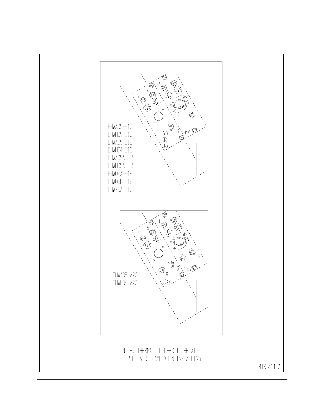
FIGURES 4E AND 4F
HEATER TERMINAL IDENTIFICATION DRAWINGS
FIGURE 4E
FIGURE 4F
Manual 2100-254E
Page 15 of 17
Page 16

FIGURE 5
WIRING DIRECTIONS
Manual 2100-254E
Page 16 of 17
Page 17
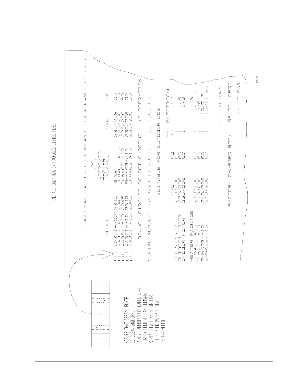
FIGURE 6
MARKING SERIAL PLATE LABEL
Manual 2100-254E
Page 17 of 17
 Loading...