

Bard EHWH24-B06, EHWA24A-A04, EHWH02A-A08, EHWA02-A05, EHWA02A-A08 Installation Instructions Manual
...Page 1

INSTALLATION INSTRUCTIONS
ELECTRIC HEAT PACKAGES
Models:
EHWH02A-A04 EHWA24A-A04
EHWH02A-A08 EHWA02-A05
EHWH24-B06 EHWA02A-A08
EHWH24B-C06 EHWA02A-A10
EHWH30-A05 EHWA24-B06
EHWH36-A05 EHWA03-A05
EHWH30-A10 EHWA03-A08
EHWH36-A10 EHWA03-A10
EHWH36-A15 EHWA03-A15
EHWH03-B06 EHWA03-B06
EHWH03-B09 EHWA03-B09
EHWH36-B15 EHWA03-B15
EHWH37-B15 EHWA03A-C15
EHWH31-C06 EHSH31-A04
EHWH03A-C15 EHSH31-A08
EHWC03A-C06 EHSH31-B06
EHWC03A-C09 EHSH31-C06
FOR USE WITH SH, WA AND WH SERIES
WALL MOUNTED AIR CONDITIONERS
AND HEAT PUMPS
(See Tables 1A, 1B and 1C for Model Usage Matrix)
BARD MANUFACTURING COMPANY
Bryan, Ohio 43506
Since 1914...Moving, ahead just as planned.
Manual: 2100-268F
Supersedes: 2100-268E
File: Volume III, Tab 18
Date: 05-28-03
Page 2

CONTENTS
Model Nomenclature Legend ............................. 1
Description1
Important ......................................................... 1
Shipping Damage ............................................... 1
Unpacking the Electric Heat Package ................ 1
Wiring Main Power ............................................. 1
Installation ......................................................... 6
Figures
Figure 1 Wiring - Main Power ......................... 5
Figure 2 Electric Heat Access Panel &
Control Panel Cover Locations ......... 7
Figure 3 Screw Mounting Holes ..................... 7
Figure 4 A Thru D ........................................... 9
Figure 4E Install Heat Package with
Two Heat Strips .............................. 10
Figure 5 Installing Heater Base and
Connecting ...................................... 11
Figure 6 Serial Plate Showing Approved
Heater Packages ............................ 12
T ables
Table 1A Approved Heater Usage Matrix ........ 2
Table 1B Approved Heater Usage Matrix ........ 3
Table 1C Approved Heater Usage Matrix ........ 3
Table 2 Electrical Data and BTU Output ....... 4
Table 3 References to Figures 4 & 5
By Model Number ............................. 8
COPYRIGHT MAY 2003
BARD MANUFACTURING COMPANY
BRYAN, OHIO 43506
Page 3
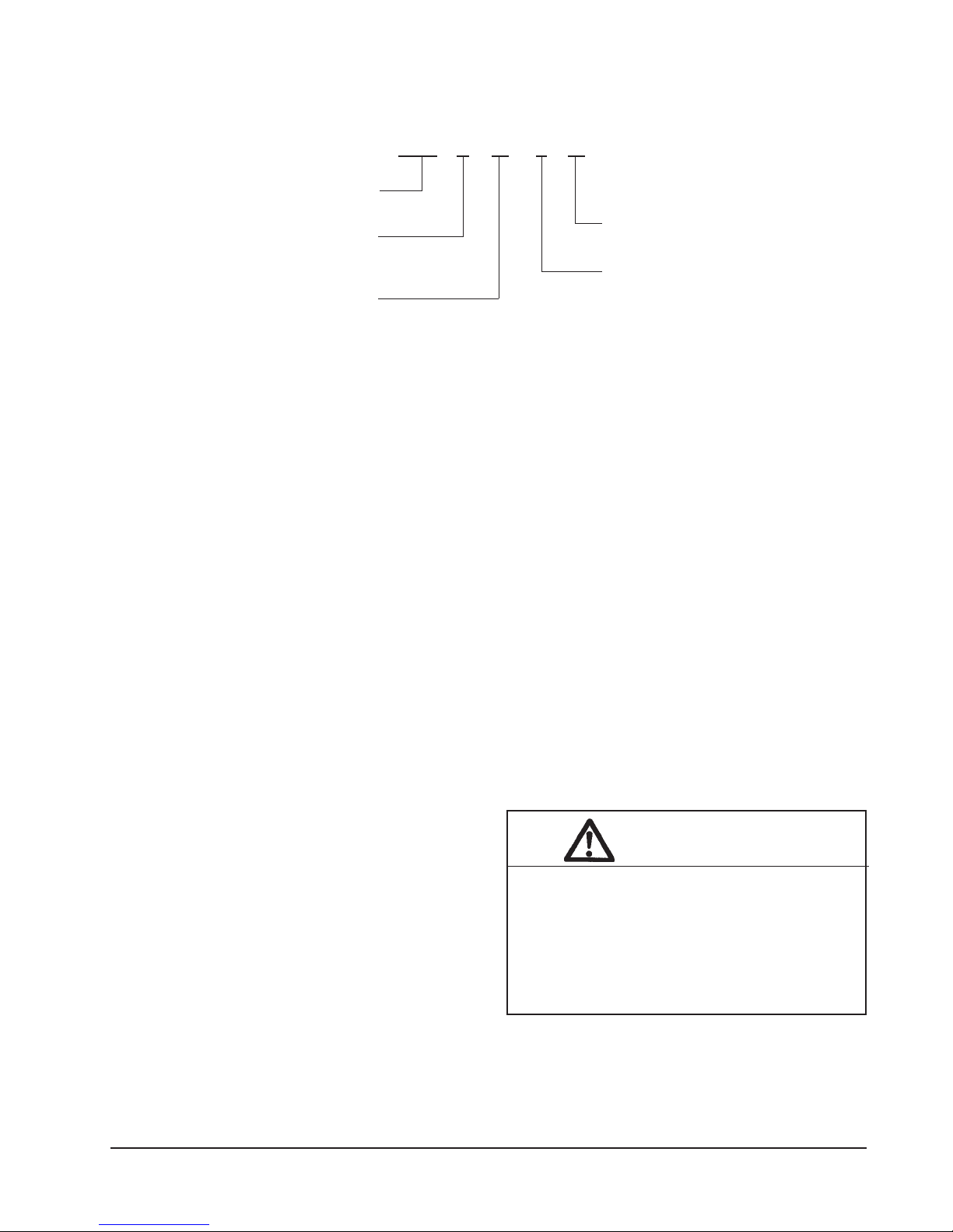
MODEL NOMENCLATURE LEGEND
EHW A 02 – A 05
Electric Heater Package
Wall Mount
A = Air Conditioner
H = Heat Pump
C = Air Conditioner & Heat Pump
Suitable For Use In
See Tables 1A, 1B, 1C
Nominal KW
5 KW
Electrical Version
A = 240/208V - 1 PH
B = 240/208V - 3 PH
C = 480V - 3 PH
DESCRIPTION
The EHWA, EHWH and EHWC series electric heater
packages are field installable heater packages suitable
for use with Bard wall mount hi boy air conditioners and
heat pumps. The packages consist of the electric heat
strip, the heater control base which includes the heat
contactors, and circuit breaker or pull disconnects,
installation instructions and wiring diagrams. See Table
1 for nominal electrical data and BTU output. Before
installation, check unit serial plate to insure the heater
package model that you intend to install is listed a
heater package that is suitable for use with the Bard
wall mount hi boy unit. See Figure 6.
IMPORTANT
The equipment covered in this manual is to be installed
by trained, experienced service and installation
technicians.
SHIPPING DAMAGE
Upon receipt of equipment, the carton should be
checked for external signs of shipping damage. If
damage is found, the receiving party must contact the
last carrier immediately, preferably in writing,
requesting inspection by the carrier's agent.
UNPACKING THE ELECTRIC HEAT
PACKAGE
Remove the heat package from the shipping carton. The
heat package must consist of the following:
1. Basic heater
2. Electric heat control base and wiring.
3. Installation instructions.
4. Wiring diagram (2), one to be applied to unit.
5. Adhesive label to remark serial plate to indicate
new model number. This is attached to the front of
these instructions.
WIRING MAIN POWER
1. On all installations, size unit power supply wiring
for the minimum circuit ampacity requirement for
the unit and heater package combination listed on
the unit serial plate.
WARNING
Install properly sized power supply leads for the
unit/heater combination minimum circuit
ampacity as listed on the unit serial plate.
Hazard of fire. Failure to install properly sized
conductors could result in fire causing damage,
bodily injury or death.
Manual 2100-268
Page 1
Page 4

SH261-A
SH311-A
SH261DA
SH311DA
WH361LA
WH361HA
WH361DA
WH361-A
WH311-A
WH301LA
WH301DA
WH301-A
WH261-A
WH242DA
WH242-A
WH183-A
WE371-D
WE301-D
WE252-D
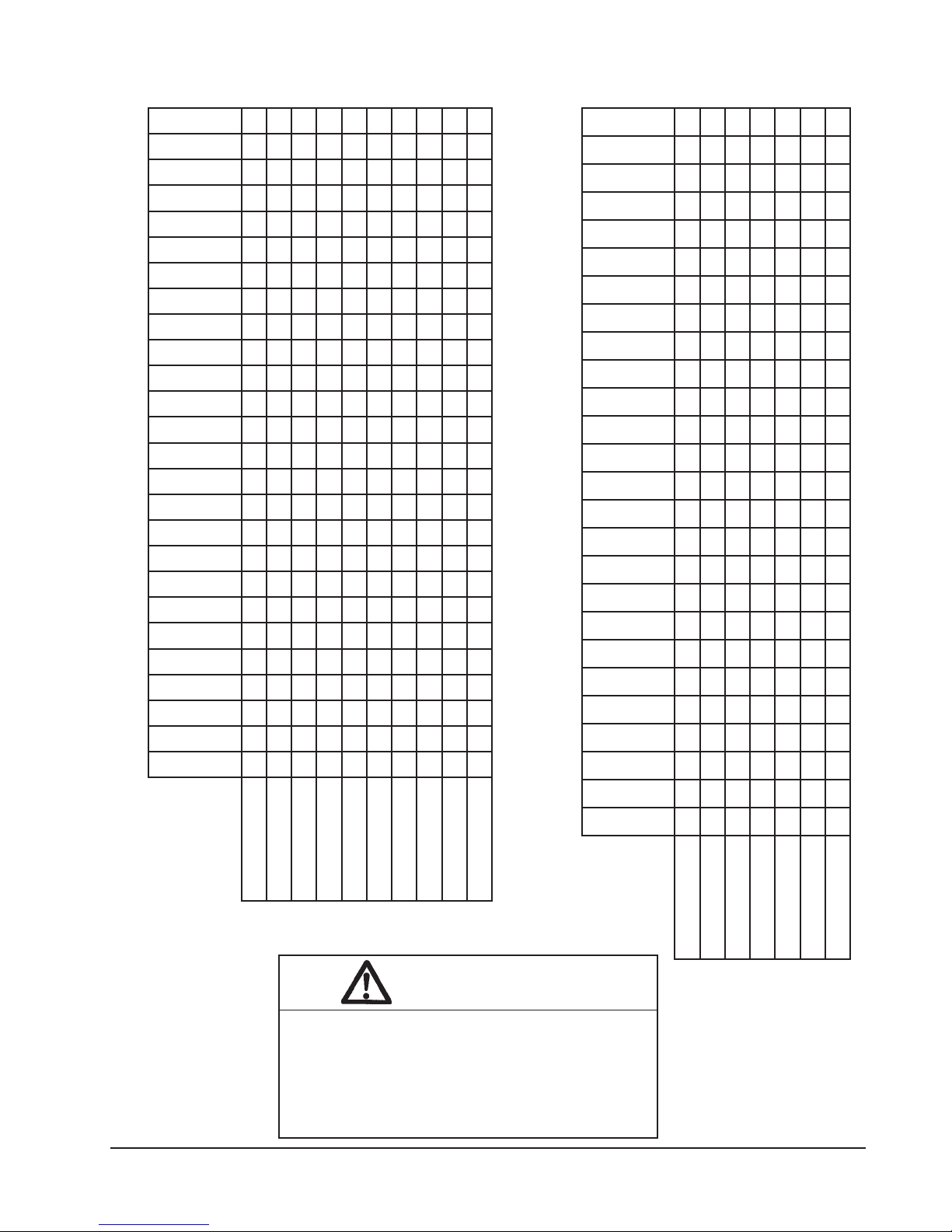
TABLE 1A
WA372-D
WA372-A
WA361-D
APPROVED HEATER USAGE MATRIX
WA361-A
WA302-D
WA302-A
WA253-D
WA253-A
WA242HA
WA242-D
WA242-A
WA182-D
WA182-A
80A-A20AWHE XXXX XX X
V022/042
esahP1
50A-20AWHE XXXX XX X
01A-A20AWHEXXX
50A-30AWHE XXXXXX XX X X
X XXX
80A-A20HWHE X XXX
40A-A20HWHE
80A-30AWHE XXX
01A-30AWHE XXXXXX XX X
40A-A42AWHEXX
51A-30AWHE XXX
50A-03HWHE XX
50A-63HWHE XX
01A-03HWHE XX
01A-63HWHE XXX
51A-63HWHE X
40A-13HSHE X X XXXX
80A-13HSHE X X XXXX
Manual 2100-268
Page 2
Page 5
V514
V064
esahP3
60C-A30CWHE X X X XX XX
90C-A30CWHE XXXXXXXXX XX XX XX
51C-A30AWHE XXXXXXXXX XX
51C-A30HWHE XX
60C-B42HWHEXX XXX
60C-13HWHE XX
60C-13HSHE XXXX
SH311-B
SH261-B
SH261DB
SH311DB
WH361LB
WH361DB
WH361-B
WH311-B
WH301LB
WH301DB
WH301-G
WH262-B
WH242DB
WH242-B
WA372TB
WA372-E
TABLE 1B
APPROVED HEATER USAGE MATRIX
WA372-B
WA361TB
WA361HB
WA361-E
WA361-B
WA302-B
WA253-B
WA242TB
WA242HB
SH311-DC
SH311-C
SH261DC
SH261-C
WH361DC
WH361-C
WH311-C
WH301DC
WH301-C
WH262-C
WH242DC
X
WH242-C
WE371-F
WE301-F
WE252-F
WA372TF
WA372-F
TABLE 1C
WA372-C
WA361TF
WA361-F
APPROVED HEATER USAGE MATRIX
WA361-C
WA302TF
WA302-F
WA242-B
V802/032
V022/042
60B-30AWHE XXX XXXX X X
90B-30AWHEXXXXX X
51B-30AWHEXXX
esahP3
60B-42AWHE XXXX
60B-30HWHE XX XX
90B-30HWHE X XX XX
60B-42HWHEX
51B-73AWHEX
51B-63HWHE X
60B-13HSHE X X XXXX
WA302-C
WA253-F
WA242-F
WARNING
Only use factory provided heaters in approved
combinations of heater models to unit models as
shown in table 1A, 1B and 1C. Failure to use
approved combinations as shown or modification
to heaters could result in fire causing damabe,
bodily injury or death.
Manual 2100-268
Page 3
Page 6

TABLE 2
ELECTRICAL DATA AND BTU OUTPUT
ledoMegakcaPretaeHstloVesahPWKlanimoNUTBlanimoN
40A-A42AWHE802/04213/4042,01/056,31
50A-20AWHE802/042157.3/5008,21/560,71
80A-A20AWHE802/0421
01A-A20AWHE802/04215.7/01006,52/031,43
60B-42AWHE802/04235.4/6053,51/574,02
40A-A20HWHE802/0421
80A-A20HWHE802/04216/8574,02/003,72
60B-42HWHE802/04235.4/6053,51/574,02
90C-B42HWHE0843
50A-30AWHE802/042157.3/5008,21/560,71
80A-30AWHE802/04216/8574,02/003,72
01A-30AWHE802/04215.7/01006,52/031,43
51A-30AWHE802/0421
60B-30AWHE802/04235.4/6053,51/574,02
90B-30AWHE802/042357.6/9530,32/517,03
51B-30AWHE802/0423
51C-A30AWHE084351591,15
51B-73AWHE802/042352.11/51004,83/591,15
50A-03HWHE802/0421
01A-03HWHE802/04215.7/01006,52/031,43
50A-63HWHE802/042157.3/5008,21/560,71
01A-63HWHE802/0421
51A-63HWHE802/042152.11/51004,83/591,15
60B-30HWHE802/04235.4/6053,51/574,02
90B-30HWHE802/0423
51B-63HWHE802/0423 52.11/51004,83/591,15
60C-A30CWHE08436 574,02
90C-A30CWHE08439 517,03
51C-A30HWHE0843
60C-13HWHE08436 574,02
40A-13HSHE802/04213/4042,01/056,31
80A-13HSHE802/04216/8574,02/003,72
60B-13HSHE802/0423
60C-13HSHE0843 5.4/6574,02
6/8574,02/003,72
3/4042,01/056,31
9 517,03
52.11/51530,32/591,15
52.11/51004,83/591,15
57.3/5008,21/560,71
5.7/01006,52/031,43
57.6/9530,32/517,03
51591,15
5.4/6053,51/574,02
Manual 2100-268
Page 4
Page 7

FIGURE 1
WIRING – MAIN POWER
MIS-365
Manual 2100-268
Page 5
Page 8

2. All heater packages covered by this manual are
factory wired for single supply circuit. The
following heater packages are field convertible to a
dual supply circuit if required or desired:
EHWA03-A15
EHWH30-A10
EHWH36-A10
EHWH36-A15
3. To convert the above heater packages to dual
circuit configuration before installation, loosen four
(4) screws holding jumper bar in place. Remove
jumper bar. Circuits A + B are now identified on
the heater package. See Figure 1.
Wire should be sized to the minimum circuit
ampacity as specified on the serial plates of units
that accept these heater package for circuits
A + B.
INSTALLATION
1. Disconnect all power to unit before installation.
WARNING
3. Remove electric heater access panel and control
panel cover, both inner and outer. See Figure 2.
4. All heaters are installed with the thermal cutoffs
positioned to the top of the unit. Install heat
strip(s) through heater access opening. Position
heat strip support rod in heater support hole 1, 2 or
3 as indicated in Table 1 and Figure 3.
On heater packages with two (2) heat strips, install
9KW heater first in position closest to the outlet air
frame. See Figure 4E.
5. Install heater control base into top of control panel
as shown in Figure 4. Secure with four (4) sheet
metal screws provided.
6. Plug mail six (6) pin connector into mating
connector mounted in control panel. See
Figure 5.
7. Connect red compressor supply lead to L1 of
terminal block. Connect black compressor supply
lead to L2 of terminal block. If three phase,
connect yellow supply lead to L3 of terminal block.
See Figure 4 and wiring diagram.
8. Route wires from heater control base up through
raceway in top right corner of control panel to the
heaters. See Figure 5.
Disconnect all power to unit before installing
heater package. Hazard of electrical shock.
Failure to disconnect power could result in injury
or death.
2. Before installation, check unit serial plate to insure
that the heater package model that you intend to
install is listed as a heater package suitable for use
with the unit.
Under no circumstance shall a heater package be
installed in a unit if the model number of the heater
package does not appear on the unit serial plate.
WARNING
Install only heater packages listed on unit serial
plate. Hazard of fire or electrical shock. Failure
to install listed heater package could result in
fire, injury or death.
9. Wire heater package per wiring diagram supplied
with this heater package. All wires are stamped
oath wire numbers that correspond with terminal
numbers on the wiring diagram and stamped
numbers on the heat strip. Limit switch wires are
terminated with insulate quick connect terminals.
See Figure 4.
10. Attach adhesive wiring diagram directly above unit
wiring diagram on inner control panel cover.
11. Recheck all wiring. Break out appropriate circuit
breaker tabs on inner control panel cover to allow
trip lever to protrude. Replace control panel and
heater access panels.
12. Resupply power to the unit and check for proper
operation.
13. Remark serial plate with self-adhesive label
attached to the front of this manual. See Figure 6.
Manual 2100-268
Page 6
Page 9

FIGURE 2
ELECTRIC HEATER ACCESS PANEL
AND CONTROL PANEL COVER LOCATIONS
FIGURE 3
SCREW MOUNTING HOLES
MIS-358
MIS-419
Manual 2100-268
Page 7
Page 10

TABLE 3
REFERENCES TO FIGURES 4 AND 5
FOR MODEL NUMBER
4erugiF
egakcaPretaeH
rebmuNledoM
.150A-20AWHEA41
.280A-A20AWHEB41
.301A-A20AWHEB41
.450A-30AWHEA41
.580A-30AWHEB41
.601A-30AWHEB41
.751A-30AWHED42
.860B-30AWHEC41
.990B-30AWHEC41
.0151B-30AWHED42
.1151C-A30AWHEE43+1
.2160B-42AWHEC41
.3151B-73AWHED43+1
.4160C-A30CWHEC41
.5190C-A30CWHEC41
.6140A-A20HWHEA41
.7180A-A20HWHEB41
.8160B-30HWHEC41
.9190B-30HWHEC41
.0251C-A30HWHEE43+1
.1260B-42HWHEC41
.2260C-B42HWHEC41
.3250A-03HWHEA41
.4201A-03HWHEB41
.5250A-63HWHEA41
.6201A-63HWHEB41
.7251A-63HWHED42
.8251B-63HWHEE43+1
.9240A-A42AWHEA41
.0360C-13HWHEC41
.1340A-13HSHEA41
.2380A-13HSHEB41
.3360B-13HSHEC41
.4360C-13HSHEC41
lanimreTretaeH
gniwarDnoitacifidnedI
3erugiF
wercSdnatroppuSdoR
noitisoPgnitnuoM
Manual 2100-268
Page 8
Page 11

FIGURE 4
A THRU D
FIGURE 4A
FIGURE 4C
FIGURE 4B
FIGURE 4D
Manual 2100-268
Page 9
Page 12

FIGURE 4E
INSTALL HEATER PACKAGE WITH
TWO HEAT STRIPS
Manual 2100-268
Page 10
MIS-364
Page 13
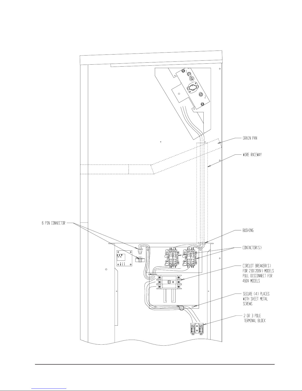
FIGURE 5
INSTALLING HEATER BASE
AND CONNECTING
MIS-422
Manual 2100-268
Page 11
Page 14

FIGURE 6
MIS-384
SERIAL PLATE SHOWING
APPROVED HEATER PACKAGES
Manual 2100-268
Page 12
 Loading...