

Bard D48L2P/BLD.10309, D36L2P/BLD.10305, D60A2P/BLD.10310, D60L2P/BLD.10303, D42A2P/BLD.10306 Installation And Service Instructions Manual
...Page 1

INSTALLATION AND SERVICE
INSTRUCTIONS
&
REPLACEMENT PARTS MANUAL
DC FREE COOLING UNIT SYSTEM
TWO (2) D-SERIES DUAL-TEC™
WALL-MOUNTED PACKAGE
AIR CONDITIONERS
&
ONE (1) BARD-LINKTM PLC
LEAD/LAG CONTROLLER
AIR CONDITIONER MODELS
D36A2P/BLD.10304 D36L2P/BLD.10305
D42A2P/BLD.10306 D42L2P/BLD.10307
D48A2P/BLD.10308 D48L2P/BLD.10309
D60A2P/BLD.10310 D60L2P/BLD.10303
CONTROLLER MODELS
LC1000-100/BLD.10293
LC1500-100/BLD.10291
NOTE: BARD-LINKTM LC1000-1000 or LC1500-100 Controllers must be used
with D-Series Wall-Mount Units
Bard Manufacturing Company, Inc.
Bryan, Ohio 43506
www.bardhvac.com
Manual : 2100-620A
Supersedes: 2100-620
Date: 3-25-15
Page 1 of 107
Page 2

CONTENTS
SECTION 1: Installation Instructions ......................................................................................................... 7
List of Necessary Materials/Tools .........................................................................................................................8
Site Preparation .................................................................................................................................................9
Wall-Mount Unit Installation .............................................................................................................................11
Wall-Mount Unit Supply Wiring ..........................................................................................................................15
Preliminary Start-Up .........................................................................................................................................19
Bard-LinkTM Controller Installation .....................................................................................................................20
System Start-Up ..............................................................................................................................................36
SECTION 2: Service Instructions ............................................................................................................... 39
General Refrigerant Information .........................................................................................................................40
Sequence of Operation .....................................................................................................................................42
Advanced Programming ....................................................................................................................................49
Using the TEC-EYE ..........................................................................................................................................54
Componentry Specifications ..............................................................................................................................57
Maintenance and Troubleshooting ......................................................................................................................64
SECTION 3: Parts Manual ............................................................................................................................ 73
D-Series Wall-Mount Unit .................................................................................................................................74
Bard-LinkTM PLC Lead/Lag Controller ..................................................................................................................88
SECTION 4: Appendices .............................................................................................................................. 91
Appendix 1: LC-Series Controller Architecture .....................................................................................................92
Appendix 2: TEC-EYE Architecture ....................................................................................................................99
FIGURES AND TABLES
Figure 1.1 Wall-Mount Unit Model Nomenclature ......8
Figure 1.2 Dimensions ..........................................10
Figure 1.3 Mounting Instructions ...........................12
Figure 1.4 Electric Heat Clearance .........................13
Figure 1.5 Wall Mounting Instructions ....................13
Figure 1.6 Wall Mounting Instructions ....................14
Figure 1.7 Common Wall Mounting Installations ......14
Figure 1.8 Circuit Routing Label ............................16
Figure 1.9 WIRING:
Figure 1.10 Adjusting the 230/208VAC Transformer ..17
Figure 1.11 WIRING:
Figure 1.12 Bard Polarity-Voltage Monitor .................18
Figure 1.13 WIRING:
Figure 1.14 Remote Temperature Sensor Install ........22
Figure 1.15 Additional Remote Temp Sensor Install ...23
Figure 1.16 Power and Signal Connections – Smoke ..24
Figure 1.17 Power/Signal Connections – Hydrogen ....25
Figure 1.18 LC1000/LC1500 Generator Run ............25
Figure 1.19 WIRING:
Figure 1.20 WIRING:
Figure 1.21 WIRING: Communication Wiring ............28
Figure 1.22 WIRING: Communication Wiring:
Controller Termination ........................... 29
Figure 1.23 WIRING: Communication Wiring:
1st Unit Termination ............................. 30
Figure 1.24 WIRING: Communication Wiring:
2nd Unit Termination ............................ 31
Figure 1.25 Controller Circuit Install ........................32
Figure 1.26 Controller Grounding Posts ....................32
Figure 1.27 WIRING:
Figure 1.28 WIRING:
Figure 1.29 Bard-LinkTM Controller Display ...............36
Figure 1.30 Clock/Scheduler Menu ..........................36
Figure 1.31 Status Display Showing Units "Online" ....36
Figure 1.32 Executing Run Test ............................... 37
VAC Supply Wiring Landing Points . 16
VDC Supply Wiring Landing Points . 17
Typical LC1000/LC1500 Wiring .. 20
LC1000 External Alarm Wiring .. 26
LC1500 External Alarm Wiring .. 27
LC1000/LC1500 Wiring Diagram .. 34
LC1500 Punch-Down Block Wiring 35
Figure 2.1 Refrigerant Sight Glass .........................41
Figure 2.2 Wall-Mount Unit Control Board ..............43
Figure 2.3 Controller Board and Terminal Block .......45
Figure 2.4 LC Series Controller Control Board .........46
Figure 2.5 Free Cooling Damper Operation ..............48
Figure 2.6 Bard-LinkTM Controller Display ...............49
Figure 2.7 Controller Status Display .......................50
Figure 2.8 TEC-EYE Display ..................................54
Figure 2.9 TEC-EYE Connection to Unit Control ......54
Figure 2.10 TEC-EYE Status Display ........................55
Figure 2.11 Fan Blade Setting .................................59
Figure 2.12 Dirty Filter Switch .................................59
Figure 2.13 Power Loss Relay Circuit .......................60
Figure 2.14 High Pressure Relay Circuit ...................60
Figure 2.15 Blower Motor Start Relay Circuit ............60
Figure 2.16 Unit Control Panel ................................61
Figure 2.17 WIRING: Unit Wiring Diagram ................62
Figure 2.18 Low Voltage Connections .......................63
Figure 2.19 Troubleshooting Motor Power Supply ......65
Figure 2.20 Troubleshooting Motor Start Command ...66
Figure 2.21 Troubleshooting Speed Voltage ...............66
Figure 2.22 VDC Polarity Check ...............................67
Figure 2.23 Verifying Incoming Voltage .....................68
Table 1.1 Electrical Specifications ..........................15
Table 1.2 Terminal Block Index ............................... 33
Table 1.3 Controller Default Settings .......................38
Table 2.1 Nominal Pressures ..................................41
Table 2.2 Blower Speed Voltage Chart .....................42
Table 2.3 Controller Default Settings .......................48
Table 2.4 Controller Programmable Features ............52
Table 2.5 Temp vs. Resistance of Temp Sensor. ........ 58
Table 2.6 Indoor Blower Performance ......................59
Table 2.7 Troubleshooting 48VDC Blower Motor ........65
Table 2.8 Blower Speed Voltage Chart .....................66
Manual 2100-620A
Page 2 of 107
Page 3
GENERAL INFORMATION
DC FREE COOLING UNIT SYSTEM (DC-FCU)
The Bard DC Free Cooling Unit system is composed of two (2) D-Series DUAL-TEC™ wall-mounted air conditioners
matched with one (1) Bard-LinkTM PLC lead/lag controller. The D-Series, specifically engineered for the telecom
market, can provide outdoor air cooling during power loss situations through the use of onsite -48VDC positive
ground battery banks.
TM
NOTE: The Bard-Link
work together. The PLC controller cannot run other Bard models or other brands of systems, nor can other
controllers or thermostats run the D-Series wall-mount units. They are a complete system, and must be used
together.
WALL-MOUNT AIR CONDITIONER UNITS
The D-Series units operate on both VAC and VDC power under normal power supply conditions. If there is loss of VAC
power supply (shore and/or back-up generator) the unit will continue to operate as free cooling or ventilation system
using the shelter’s VDC power. The indoor blower and free cooling unit operate from -48VDC and no inverter is required.
The units will supply 100% of rated cooling airflow in free cooling mode with ability to exhaust the same amount
through the unit itself without any additional relief openings in the shelter.
Each of these units are fully charged with refrigerant and have auxilliary heat installed.
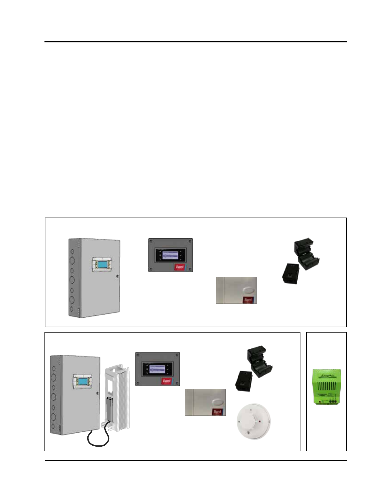
BARD-LINKTM PLC CONTROLLER
Two models: LC1000-100 and LC1500-100 (controllers and accessories included with controllers shown below).
PLC lead/lag controller and the D-Series wall-mount units are designed specifically to
LC1000-100 Series – New Shelters Only
TEC-EYE Hand-Held
Diagnostic Tool
Programmable Logic
Controller
Remote Temperature
Sensor with 35' Cable
LC1500-100 Series – EOL and All HVAC Replacement Projects
TEC-EYE Hand-Held
Diagnostic Tool
Programmable
Logic Controller
with Attached
66 Punch-Down
Block
Remote Temperature
Sensor with 35' Cable
Communication
EMI Filters
Communication
EMI Filters
VDC
Smoke
Detector
OPTIONAL
8301-061
VDC
Hydrogen
Detector
Manual 2100-620A
Page 3 of 107
Page 4

The equipment covered in this manual is to be installed
by trained, experienced service and installation
technicians.
The refrigerant system is completely assembled and
charged. All internal wiring is complete.
The unit is designed for use with or without duct work.
Flanges are provided for attaching the supply and return
ducts.
These instructions explain the recommended method
to install the air cooled self-contained unit and the
electrical wiring connections to the unit.
These instructions and any instructions packaged with
any separate equipment required to make up the entire
air conditioning system should be carefully read before
beginning the installation. Note particularly “Starting
Procedure” and any tags and/or labels attached to the
equipment.
While these instructions are intended as a general
recommended guide, they do not supersede any national
and/or local codes in any way. Authorities having
jurisdiction should be consulted before the installation
is made. See Page 3 for information on codes and
standards.
Sizing of systems for proposed installation should be
calculated by AT&T-specific methods/software using
regional climatic data and standards. The air duct
should be installed in accordance with the Standards
of the National Fire Protection Association for the
Installation of Air Conditioning and Ventilating Systems
of Other Than Residence Type, NFPA No. 90A, and
Residence Type Warm Air Heating and Air Conditioning
Systems, NFPA No. 90B. Where local regulations are at
a variance with instructions, installer should adhere to
local codes.
Shipping Damage
Upon receipt of equipment, the cartons should be
checked for external signs of shipping damage. If
damage is found, the receiving party must contact
the last carrier immediately, preferably in writing,
requesting inspection by the carrier’s agent.
These units must remain in upright position at all
times.
ADDITIONAL PUBLICATIONS
These publications can help you install the air
conditioner or heat pump. You can usually find these
at your local library or purchase them directly from the
publisher. Be sure to consult current edition of each
standard.
National Electrical Code ...................... ANSI/NFPA 70
Standard for the Installation of Air Conditioning
and Ventilating Systems ...................ANSI/NFPA 90A
Standard for Warm Air Heating
and Air Conditioning Systems ............ANSI/NFPA 90B
Load Calculation for Residential Winter
and Summer Air Conditioning ............. ACCA Manual J
Duct Design for Residential Winter and Summer
Air Conditioning and Equipment Selection
....................................................... ACCA Manual D
For more information, contact these publishers:
Air Conditioning Contractors of America (ACCA)
1712 New Hampshire Ave. N.W.
Washington, DC 20009
Telephone: (202) 483-9370
Fax: (202) 234-4721
American National Standards Institute (ANSI)
11 West Street, 13th Floor
New York, NY 10036
Telephone: (212) 642-4900
Fax: (212) 302-1286
American Society of Heating, Refrigeration and Air
Conditioning Engineers, Inc. (ASHRAE)
1791 Tullie Circle, N.E.
Atlanta, GA 30329-2305
Telephone: (404) 636-8400
Fax: (404) 321-5478
National Fire Protection Association (NFPA)
Batterymarch Park
P. O. Box 9101
Quincy, MA 02269-9901
Telephone: (800) 344-3555
Fax: (617) 984-7057
Manual 2100-620A
Page 4 of 107
Page 5
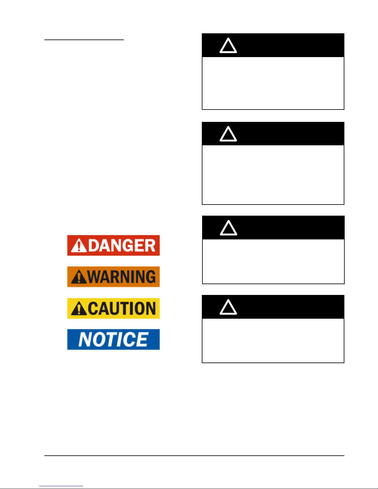
ANSI Z535.5 Definitions:
Danger: Indicate[s] a hazardous situation which, if
not avoided, will result in death or serious injury. The
signal word “DANGER” is to be limited to the most
extreme situations. DANGER [signs] should not be used
for property damage hazards unless personal injury risk
appropriate to these levels is also involved.
Warning: Indicate[s] a hazardous situation which, if
not avoided, could result in death or serious injury.
WARNING [signs] should not be used for property
damage hazards unless personal injury risk appropriate
to this level is also involved.
Caution: Indicate[s] a hazardous situation which, if
not avoided, could result in minor or moderate injury.
CAUTION [signs] without a safety alert symbol may be
used to alert against unsafe practices that can result in
property damage only.
Notice: [this header is] preferred to address practices
not related to personal injury. The safety alert symbol
shall not be used with this signal word. As an
alternative to “NOTICE” the word “CAUTION” without
the safety alert symbol may be used to indicate a
message not related to personal injury.
!
WARNING
Electrical shock hazard.
Have a properly trained individual perform
these tasks.
Failure to do so could result in electric shock
or death.
!
WARNING
Fire hazard.
Maintain minimum 1/4” clearance between the
supply air duct and combustible materials in
the rst 3’ feet of ducting.
Failure to do so could result in re causing
damage, injury or death.
!
WARNING
Heavy item hazard.
Use more than one person to handle unit.
Failure to do so could result in unit damage or
serious injury.
!
CAUTION
Cut hazard.
Wear gloves to avoid contact with sharp
edges.
Failure to do so could result in personal injury.
Manual 2100-620A
Page 5 of 107
Page 6

Manual 2100-620A
Page 6 of 107
Page 7

SECTION 1:
INSTALLATION
INSTRUCTIONS
Manual 2100-620A
Page 7 of 107
Page 8
LIST OF NECESSARY MATERIALS/TOOLS
Additional hardware and miscellaneous supplies are needed for installation. These items are field supplied and must
be sourced before installation. This list also includes tools needed for installation.
LIST OF MATERIALS/TOOLS
• Personal protective equipment/safety devices
• Supply/return grilles
• Field-fabricated sleeves (if necessary)
• 5/16" diameter anchor/carriage/lag bolts
• 7/8" diameter washers
• Caulking materials
• Miscellaneous hand and power tools and jobsite or
shop materials
• Lifting equipment with the necessary capacity and
rigging to safely move/install the systems
• Electrical supplies
- Two (2) 20A circuit breakers for the shelter DC
power plant (one per wall-mount unit)
- One (1) 5A circuit breaker for the shelter DC
power plant (for the Bard-Link
TM
controller)
- Two (2) various size circuit breakers for
the shelter AC breaker box (see Table 1.1:
Electrical Specifications on page 15)
- High-voltage wire of various gauges (see Table
1.1)
- Communication wire: 2-wire, 18 gauge,
shielded with drain
- 18 gauge non-shielded wire for connecting
smoke detector (and hydrogen detector and/or
generator, if applicable) to controller
-
CAT 6 Ethernet cable of field-determined length
(for remote communication, if applicable)
- Miscellaneous electrical supplies including
rigid/flexible conduit and fittings, junction
boxes, wire connectors and supports
The following are required and must be sourced
prior to installation of these units.
• Two (2) 20A circuit breakers for the shelter DC
power plant (one per wall-mount unit)
• One (1) 5A circuit breaker for the shelter DC
TM
power plant (for the Bard-Link
controller)
Circuit breakers for Emerson Network Power (ENP)
power plants (used in most telecomm shelters built
today) are available directly through the following
distributors:
• Emerson Network Power: 440.288.1122
• Master Electronics: 888.473.5297 or
www.onlinecomponents.com
Emerson Network Power (ENP) Part Numbers
• 20A circuit breaker: P/N 101601
• 5A circuit breaker: P/N 101598
Always confirm the application before ordering.
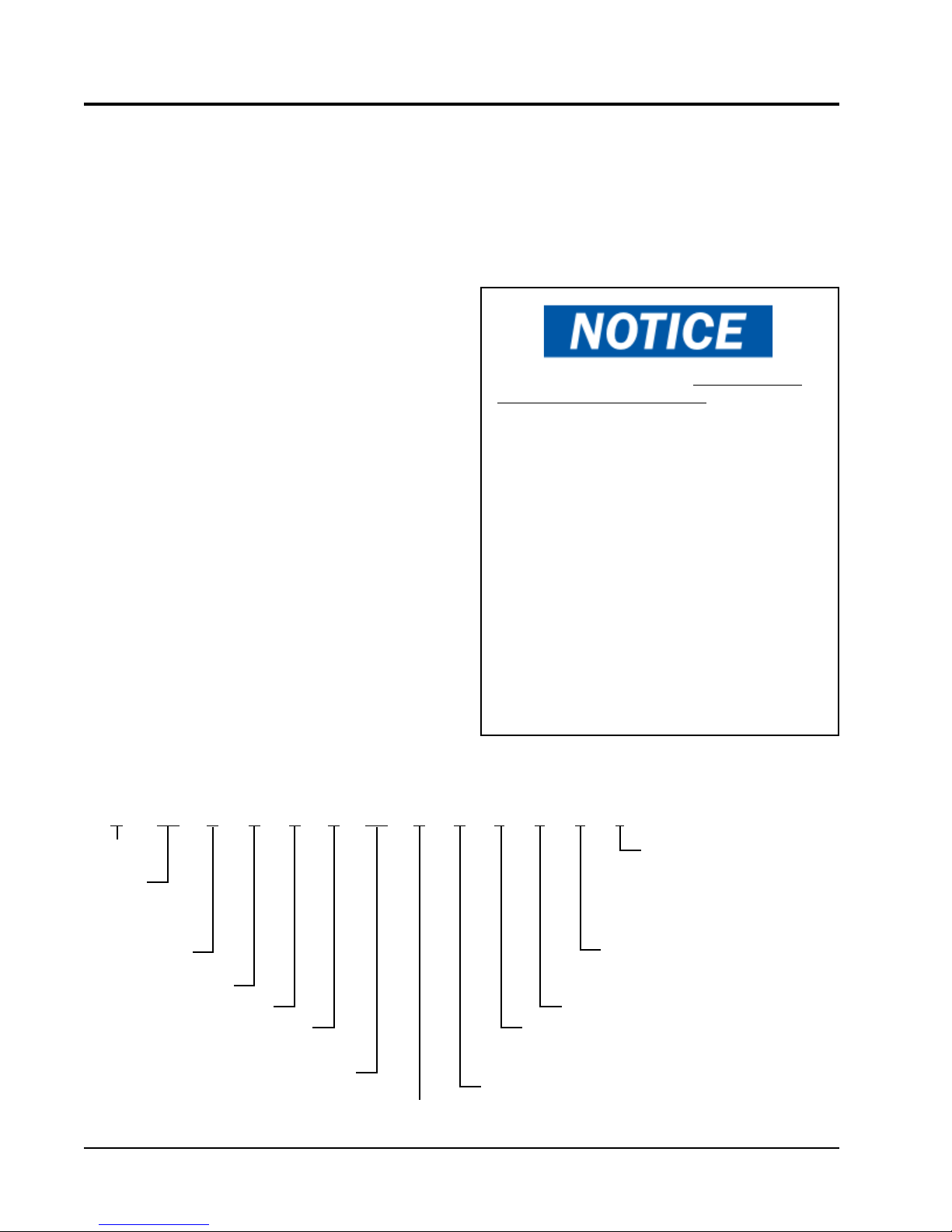
D-Series DUAL-TEC™ Wall-Mount Unit Model Nomenclature
D 36 A 2 P A 05 4 P X X X J
MODEL
SERIES
CAPACITY
36 – 3 Ton
42 – 3½ Ton
48 – 4 Ton
60 – 5 Ton
A – Right Hand
L – Left Hand
REVISION
PLC
VOLTS & PHASE
A – 230/208-60-1
B – 230/208-60-3
05 – 5 KW
06 – 6 KW
09 – 9 KW
10 – 10 KW
Manual 2100-620A
Page 8 of 107
KW
FIGURE 1.1
-48VDC
Free Cooling
Unit
CONTROL MODULES
J – High Pressure Switch, Low Pressure
Switch, Compressor Control Module,
Low Ambient Control, Alarm Contacts,
Start Assist
C – J Module + Compressor Crankcase
Heater
COIL OPTIONS
X – Standard
3 – Phenolic Coated Evaporator and
Condenser
SPECIAL FEATURES
COLOR OPTIONS
X – Beige
1 – White
4 – Buckeye Gray
FILTER OPTIONS
P – 2-Inch Pleated (MERV 8)
M – 2-Inch Pleated (MERV 11)
Page 9
SITE PREPARATION
NEW SHELTER INSTALLATION VS.
RETROFIT INSTALLATION
These installation instructions cover both new shelter
installations and retrofit installations. Each installation
is unique and may require special accomodations and
modifications. Although Bard Manufacturing follows a
long-established tradition of manufacturing equipment
using industry standard dimensions for building
penetration, it is occasionally necessary to move or
enlarge supply and return openings when replacing
non-standardized equipment in a retrofit application.
MINIMUM CLEARANCE
D-Series wall-mount air conditioners are available in
both right-hand access models and left-hand access
models. Right-hand access models have the heat strip
access panel, external circuit breakers access panel
and internal controls access panel on the right side of
the unit. Left-hand access models are a mirror image
of the right-hand access models, and allow two wallmount units to be placed in relatively close proximity
and yet still allow complete acess for maintenance and
repair.
On side-by-side installations, maintain a minimum of
26" clearance on control side to allow access to control
panel and heat strips, and to allow proper airflow to the
outdoor coil. For installations where units are installed
with both control panels facing each other (inward),
maintain a minimum of 36" clearance to allow access.
Additional clearance may be required to meet local or
national codes.
Care should be taken to ensure that the recirculation
and obstruction of condenser discharge air does not
occur. Recirculation of condenser discharge air can
be from either a single unit or multiple units. Any
object such as shrubbery, a building or a large object
can cause obstructions to the condenser discharge air.
Recirculation or reduced airflow caused by obstructions
will result in reduced capacity, possible unit pressure
safety lockouts and reduced unit service life.
For units with blow through condensers, such as the
D-Series units, it is recommended there be a minimum
distance of 10' between the front of the unit and
any barrier or 20' between the fronts of two opposing
(facing) units.
CLEARANCE TO COMBUSTIBLES
!
WARNING
Fire hazard.
Maintain minimum 1/4” clearance between the
supply air duct and combustible materials in
the rst 3’ feet of ducting.
Failure to do so could result in re causing
damage, injury or death.
The unit itself is suitable for 0" clearance, but the
supply air duct flange and the first 3' of supply air duct
require a minimum of 1/4" clearance to combustible
material. However, it is generally recommended that
a 1" clearance is used for ease of installation and
maintaining the required clearance to combustible
material. See Figure 1.3 on page 12 for details on
opening sizes.
Minimum Clearances Required to
Combustible Materials
MODELS
All covered by this
manual
SUPPLY AIR DUCT
FIRST 3'
1/4" 0"
CABINET
MODEL IDENTIFICATION
Identify the specific model using the model
nomenclature information found in Figure 1.1 and/
or model/serial tag found on the unit on the opposite
side of the control and access panels. See Figure 1.2
on page 10 for dimensions and critical installation
requirements.
Clearances Required for Service Access
and Adequate Condenser Airflow
MODELS LEFT SIDE RIGHT SIDE
All covered by this manual 26" 26"
Units with control panels
facing each other (inward)
36" between units
Manual 2100-620A
Page 9 of 107
Page 10
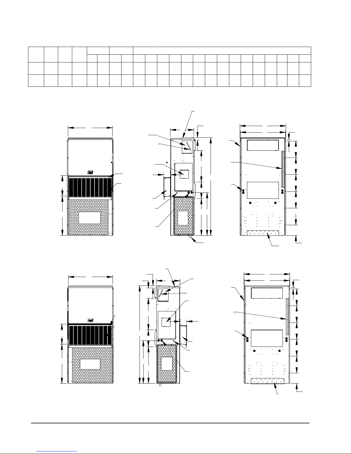
FIGURE 1.2
DRAIN
ENTRANCE
4° PITCH
RAIN HOOD
BUILT IN
PANEL
ACCESS
HEATER
(LOCKABLE)
VENT HOOD
ACCESS PANEL
DISCONNECT
ENTRANCE
ELECTRICAL
LOW VOLTAGE
C. BREAKER/
HIGH VOLTAGE
ELECTRICAL
SIDE VIEW
JDK
H
7"
C
2.13
I
ELECTRIC HEAT
Top Rain
Flashing
Shipping
Location
DOOR
AIR
VENTILIATION
VENT HOOD
Cond.
Air
Inlet
FRONT VIEW
F
G
W
SUPPLY AIR
OPENING
OPENING
RETURN AIR
Brackets
(Built In)
Mounting
Optional
Electrical
Entrances
Side Wall
BOTTOM
INSTALLATION
BRACKET
BACK VIEW
S
E
T
O
S
S
S
S
R
Air Outlet
Condenser
Dimensions of Basic Unit for Architectural and Installation Requirements (Nominal)
Width
Depth
Model
D36A/L
D42A/L
D48A/L
D60A/L
(W)
42.075 22.432 84.875 9.88 29.88 15.88 29.88 43.88 13.56 31.66 30.00 32.68 26.94 34.69 32.43 3.37 43.00 23.88 10.00 1.44 16.00 1.88
42.075 22.432 93.000 9.88 29.88 15.88 29.88 43.88 13.56 37.00 30.00 40.81 35.06 42.81 40.56 3.37 43.00 31.00 10.00 1.44 16.00 10.00
Height
(D)
Supply Return
(H)
A B C B E F G I J K L M N O P Q R S T
All dimensions are in inches. Dimensional drawings are not to scale.
D**A
RIGHT
HAND
UNIT
D**L
F
G
FRONT VIEW
W
Condenser
Air Outlet
W
HEATER
ACCESS
PANEL
ELECTRIC HEAT
C. BREAKER/
DISCONNECT
ACCESS PANEL
(LOCKABLE)
VENT HOOD
DOOR
VENTILIATION
AIR
VENT HOOD
LOW VOLTAGE
ELECTRICAL
ENTRANCE
HIGH VOLTAGE
ELECTRICAL
ENTRANCE
2.13
A
7"
BUILT IN
RAIN HOOD
4° PITCH
LEFT
HAND
UNIT
VENT HOOD
DOOR
VENTILIATION
F
G
Condenser
Air Outlet
AIR
I
H
C
J
K
D
Cond.
Air
Inlet
Cond.
Air
Inlet
SIDE VIEW
BUILT IN
RAIN HOOD
4° PITCH
2.13
I
C
JDK
DRAIN
HEATER
ACCESS
PANEL
ELECTRIC HEAT
C. BREAKER/
DISCONNECT
ACCESS PANEL
(LOCKABLE)
7"
VENT HOOD
LOW VOLTAGE
ELECTRICAL
ENTRANCE
HIGH VOLTAGE
ELECTRICAL
ENTRANCE
H
Side Wall
Mounting
Brackets
(Built In)
Optional
Electrical
Entrances
Top Rain
Flashing
Shipping
Location
Side Wall
Mounting
Brackets
(Built In)
Top Rain
Flashing
Shipping
Location
Optional
Electrical
Entrances
SUPPLY AIR
OPENING
RETURN AIR
OPENING
BACK VIEW
SUPPLY AIR
OPENING
RETURN AIR
OPENING
E
O
E
O
R
S
S
S
S
S
BOTTOM
INSTALLATION
BRACKET
S
S
S
S
S
T
R
BACK VIEW
Manual 2100-620A
Page 10 of 107
SIDE VIEW
BACK VIEW
BOTTOM
INSTALLATION
BRACKET
MIS-3618
T
Page 11
WALL-MOUNT UNIT INSTALLATION
MOUNTING THE UNITS
!
WARNING
Heavy item hazard.
Use more than one person to handle unit.
Failure to do so could result in unit damage or
serious injury.
NOTE: It may be best to spot some electrical knockouts
(such as those located on the back of the wallmount unit) before units are mounted and access is
unavailable or limited (see Figure 1.2 to locate prepunched knockouts).
Two holes for the supply and return air openings must
be cut through the wall as shown in Figure 1.3 on page
12. On wood frame walls, the wall construction must
be strong and rigid enough to carry the weight of the
unit without transmitting any unit vibration. Concrete
block walls must be thoroughly inspected to insure that
they are capable of carrying the weight of the installed
unit.
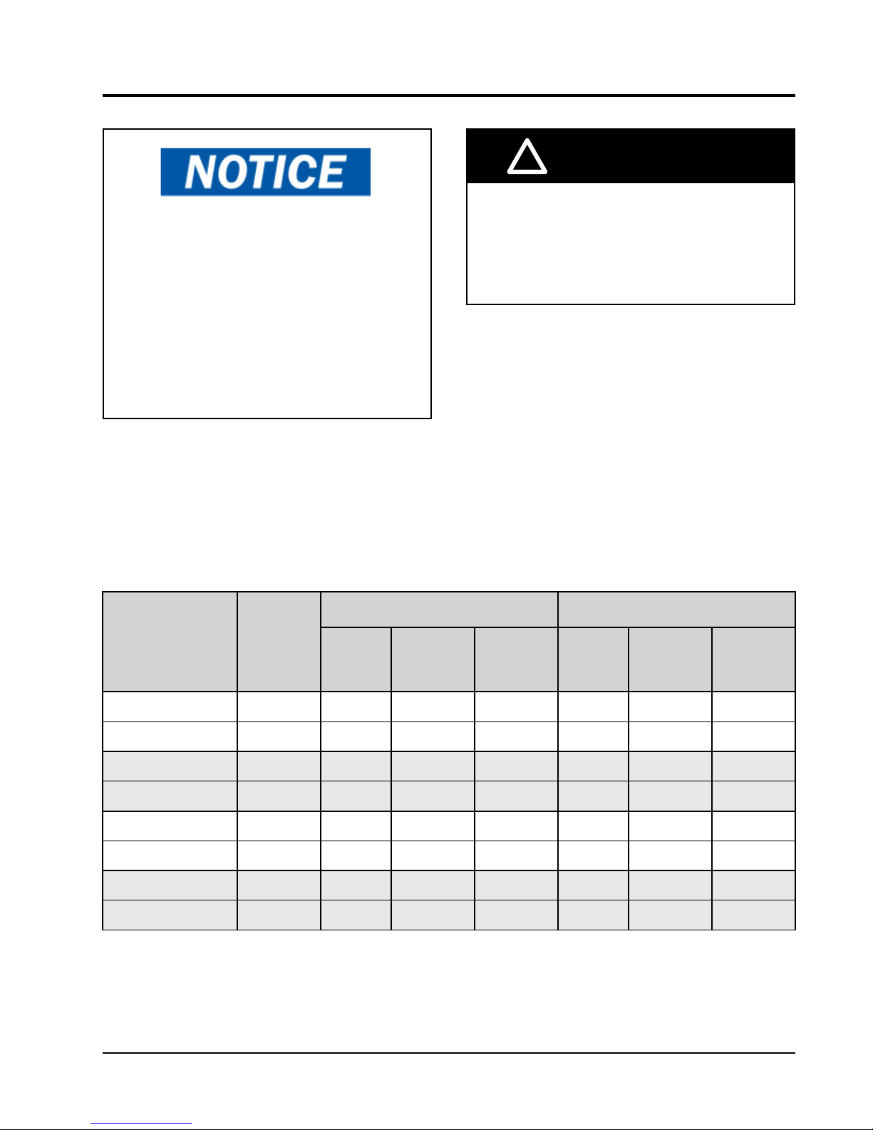
NOTICE
AT&T National Standards forbids the use of
any adaptor or transitional curbs for use in
the installation of wall-mount HVAC systems.
If existing supply and return penetrations
do not match new requirements, those
openings must be modied to meet the
needs of the new equipment.
2. The unit itself is suitable for 0" clearance, but the
supply air duct flange and the first 3' of supply
air duct require a minimum of 1/4" clearance to
combustible material. However, it is generally
recommended that a 1" clearance is used for
ease of installation and maintaining the required
clearance to combustible material. See Figure 1.3
for details on opening sizes.
3. Locate and mark lag bolt locations and location for
optional bottom mounting bracket, if desired (see
Figure 1.3).
4. Mount bottom mounting bracket (if used).
5. If desired, hook top rain flashing (attached to frontright of supply flange for shipping) under back
bend of top.
6. Position unit in opening and secure with 5/16" lag/
anchor/carriage bolts; use 7/8" diameter flat washers
on the lag bolts. It is recommended that a bead
of silicone caulking be placed behind the side
mounting flanges.
7. Secure optional rain flashing to wall and caulk
across entire length of top (see Figure 1.3).
8. For additional mounting rigidity, the return air
and supply air frames or collars can be drilled
and screwed or welded to the structural wall itself
(depending upon wall construction). Be sure to
observe required clearance if combustible wall.
9. A plastic drain hose extends from the drain pan at
the top of the unit down to the unit base. There are
openings in the unit base for the drain hose to pass
through. In the event the drain hose is connected
to a drain system of some type, it must be an open
or vented type system to assure proper drainage.
In retrofit (unit replacement) installations, the openings
cut for the original equipment may not line up exactly
with needs of this installation. Modifications may need
to be made, such as increasing or decreasing the size
of the wall cutouts. The existing bolt placement may
not line up in which case the original bolts would need
to be removed or cut away.
1. These units are secured by wall mounting flanges
which secure the unit to the outside wall surface at
both sides. A bottom mounting bracket, attached
to skid for shipping, is provided for ease of
installation, but is not required.
Manual 2100-620A
Page 11 of 107
Page 12
SUPPLIED
RAIN FLASHING
FOAM AIR SEAL
WALL STRUCTURE
1/4" CLEARANCE ON ALL
FOUR SIDES OF SUPPLY
AIR DUCT IS REQUIRED
MATERIALS
FROM COMBUSTABLE
PANEL
DUCT
SUPPLY AIR
RETURN AIR
OPENING
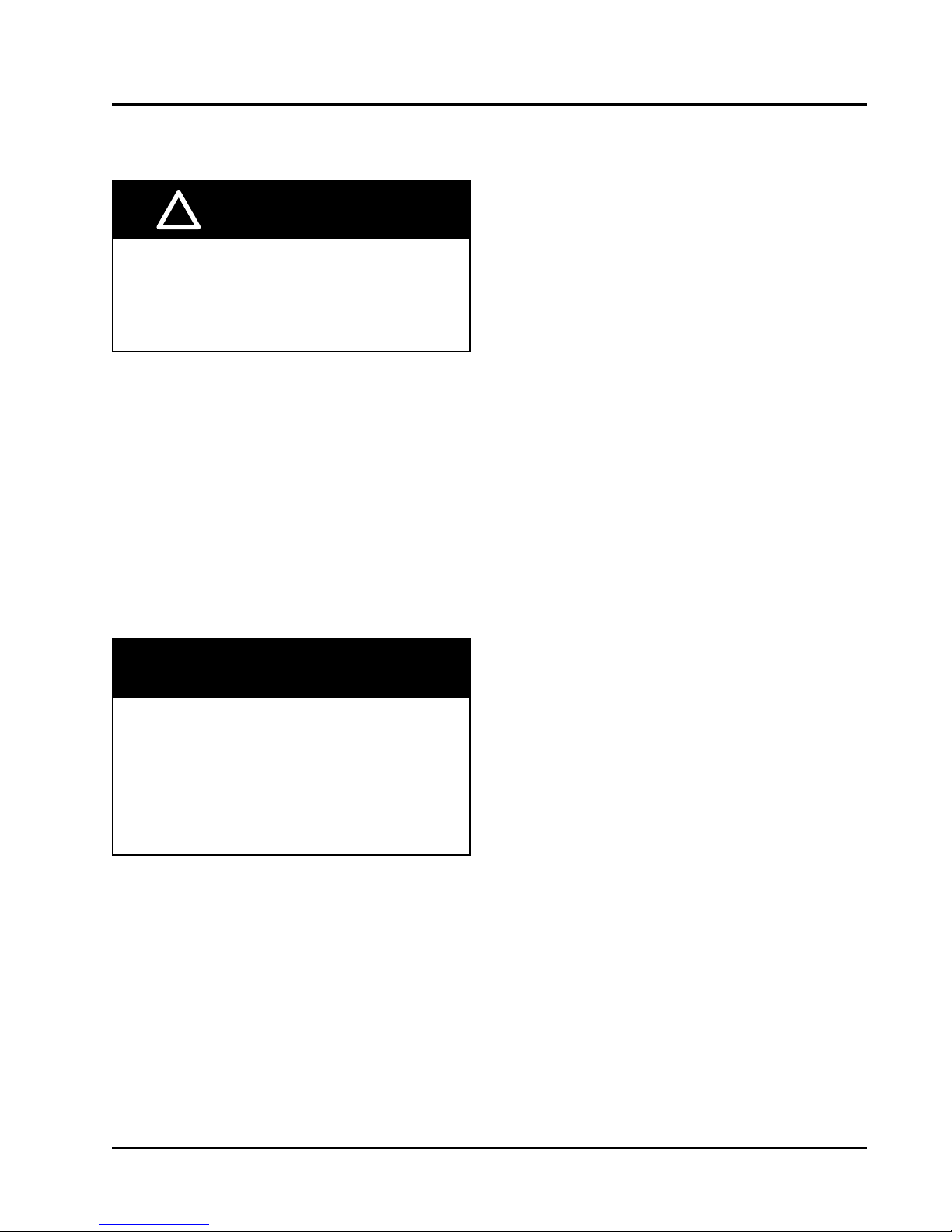
NOTES:
IT IS RECOMMENDED THAT A BEAD OF
SILICONE CAULKING BE PLACED BEHIND
THE SIDE MOUNTING FLANGES AND UNDER
MIS-3354
TOP FLASHING AT TIME OF INSTALLATION.
Right Side View
TOP.
FIGURE 1.3
SEAL WITH BEAD
OF CAULKING ALONG
ENTIRE LENGTH OF
Mounting Instructions
A B C D E
HEATER ACCESS
WALL
TOP
29
2
B
E
16"
6 1/4 1 1/4 29 3/4
10 1/2
30 1/2
32 12 5 1/2
A CC
Supply Opening
Return Opening
30"
"
1
2
6
"
7
8
"
1
8
3
4"
3"
3
"
1
8
2
"
1
2
Typ.
1"
4"
Typ.
" 6
1
2
6
Wall Opening and Hole Location View
1
D
16"
16"
16"
16"
1
16"
"
7
8
1
2
COMBUSTIBLE MATERIALS
1/4" MIN. CLEARANCE FROM
REQUIRED DIMENSIONS TO MAINTAIN
REQUIRED DIMENSIONS TO MAINTAIN
RECOMMENDED 1" CLEARANCE FROM
COMBUSTIBLE MATERIALS
Manual 2100-620A
Page 12 of 107
Page 13
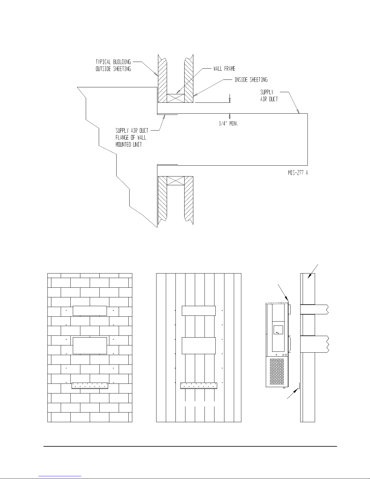
FIGURE 1.4
DUCT
OPENING
RETURN AIR
SUPPLY AIR
WOOD FRAME WALL INSTALLATION
OPENING
WALL BEFORE
MOUNT ON UNIT
OPENING
BEFORE INSTALLATION
BOTTOM MOUNTING
CONCRETE BLOCK WALL INSTALLATION
BRACKET. MOUNT ON
OPENING
WOOD OR STEEL SIDING
OPENING
INSTALLING UNIT.
RETURN AIR
WALL STRUCTURE
RETURN AIR
SUPPLY AIR
FACTORY SUPPLIED
RAIN FLASHING.
SUPPLY AIR
MIS-548 A
SIDE VIEW
Electric Heat Clearance
Wall Mounting Instructions
See FIGURE 2 – Mounting Instructions
FIGURE 1.5
Manual 2100-620A
Page 13 of 107
Page 14
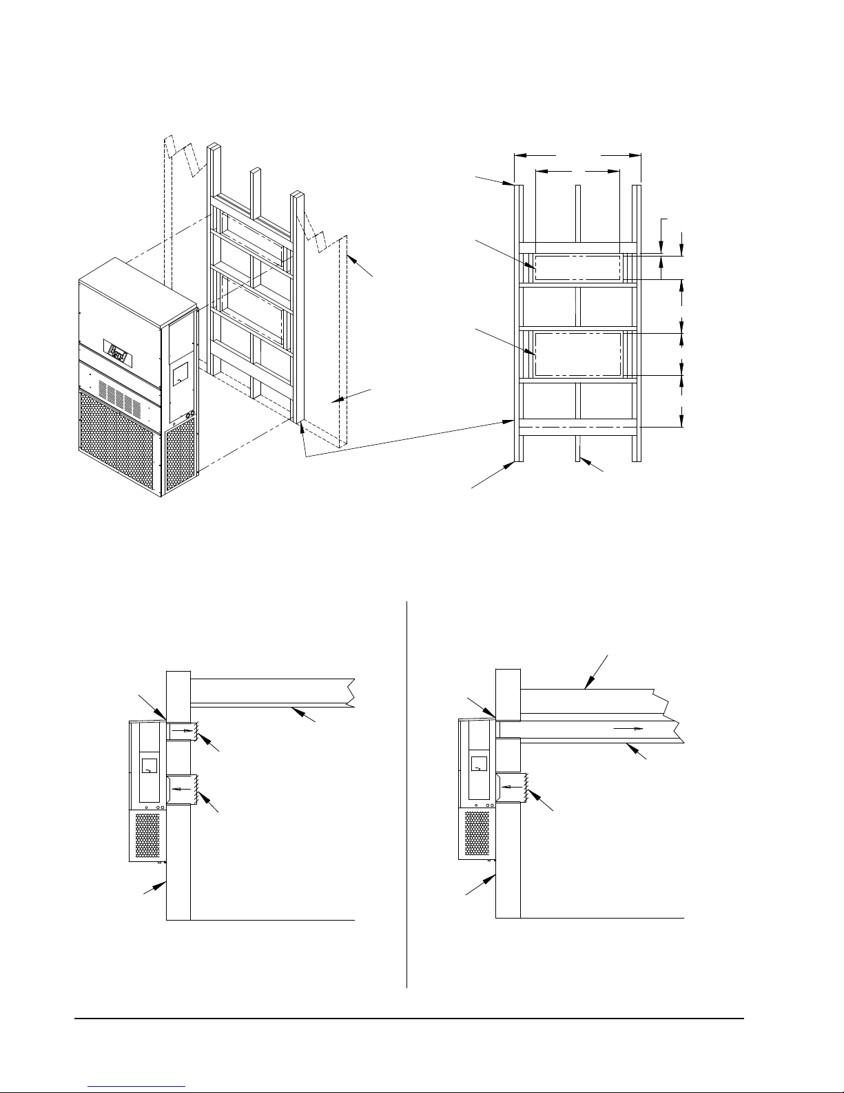
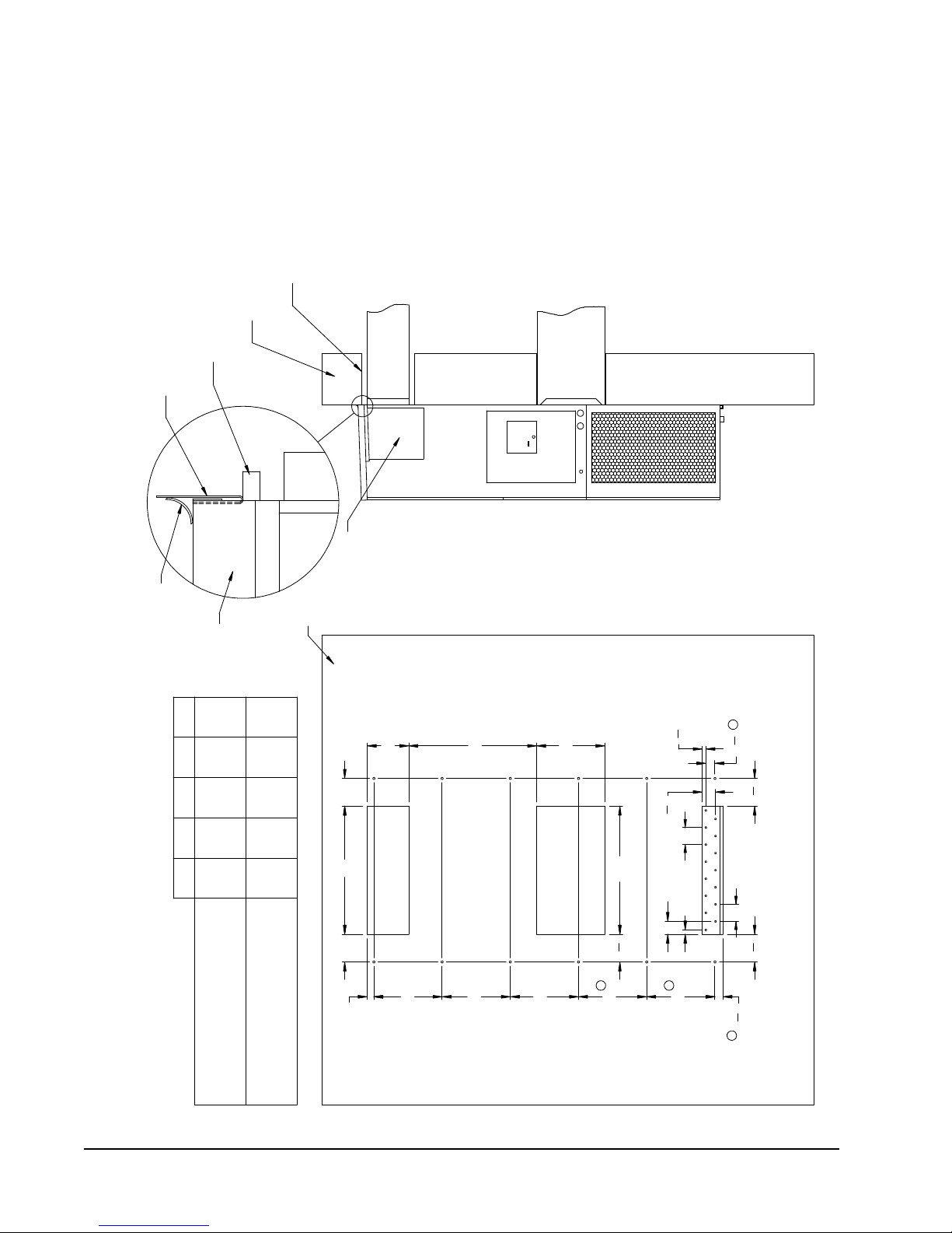
FIGURE 1.6
I
A
C
K
E + 1.000
B
1.000
SUPPLY DUCT
OVER FRAME
INTERIOR FINISHED WALL
ALL AROUND DUCT
FRAMING MATERIAL
EXTERIOR FINISH WALL
OPENING
FOR ACTUAL DIMENSIONS.
2 x 4'S, 2 x 6'S &/OR
STRUCTURAL STEEL
ATTACH TO TOP
1.000" CLEARANCE
1.000" CLEARANCE
PLATE OF WALL
C
SEE UNIT DIMENSIONS, FIGURE 2,
OPENING
RETURN DUCT
2 x 6
ATTACH TO BOTTOM
OVER FRAME
PLATE OF WALL
L
THIS STRUCTURAL MEMBER
LOCATED TO MATCH STUD
SPACING FOR REST OF WALL.
A SECOND MEMBER MAY BE
REQUIRED FOR SOME WALLS.
MIS-549 B
ALL AROUND DUCT
SUPPLY DUCT MAY BE LOCATED IN AN ATTIC
OPENING W/ GRILLE
SUPPLY AIR DUCT
RAFTERS
RAFTERS
RETURN AIR
OPENING W/ GRILLE
DUCTED SUPPLY
OR BELOW CEILING RAFTERS AS SHOWN
FINISHED CEILING SURFACE
RAIN
FLASHING
RAIN
FLASHING
RETURN AT UNITNO DUCT
RETURN AIR
FINISHED CEILING SURFACE
FREE AIR FLOW
OUTSIDE
WALL
OUTSIDE
WALL
SUPPLY AIR DUCT
W/ GRILLE
Wall Mounting Instructions
FIGURE 1.7
Common Wall Mounting Installations
Manual 2100-620A
Page 14 of 107
Page 15
WALL-MOUNT UNIT SUPPLY WIRING
All models covered by this installation
instruction require dual power sources:
VAC utility power to run the compressor, heat
and outdoor fan motor and -48 VDC power
to operate the indoor blower and DC free
cooling damper.
!
WARNING
Electrical shock hazard.
Have a properly trained individual perform
these tasks.
Failure to do so could result in electric shock
or death.
These units require a positive ground
-48 VDC copper conductor field wire
connection. Refer to the unit wiring diagram
for more information.
Refer to the unit rating plate or Table 1.1 for wire
sizing information and maximum fuse or circuit breaker
size. Each outdoor unit is marked with a “Minimum
Circuit Ampacity”. The field wiring used must be sized
to carry that amount of current. All models are suitable
only for connection with copper wire. Each unit and/or
wiring diagram will be marked “Use Copper Conductors
Only”. These instructions must be adhered to. Refer
to the National Electrical Code (NEC) for complete
current carrying capacity data on the various insulation
grades of wiring material. All wiring must conform to
NEC and all local codes.
TABLE 1.1
Electrical Specifications
AC POWER CIRCUIT DC POSITIVE GROUND POWER CIRCUIT
Model
D36A2PA05/D36L2PA05
D36A2PA10/D36L2PA10
D36A2PB06/D36L2PB06
D36A2PB09/D36L2PB09
D42A2PA05/D42L2PA05
D42A2PA10/D42L2PA10
D42A2PB06/D42L2PB06
D42A2PB09/D42L2PB09
D48A2PA05/D48L2PA05
D48A2PA10/D48L2PA10
D48A2PB06/D48L2PB06
D48A2PB09/D48L2PB09
D60A2PA05/D60L2PA05
D60A2PA10/D60L2PA10
D60A2PB06/D60L2PB06
D60A2PB09/D60L2PB09
These “Minimum Circuit Ampacity” values are to be used for sizing the field power conductors. Refer to the National Electric Code (latest
version), Article 310 for power conductor sizing.
CAUTION: When more than one field power circuit is run through one conduit, the conductors must be derated. Pay special attention to
note 8 of Table 310 regarding Ampacity Adjustment Factors when more than three (3) current carrying conductors are in a
raceway.
Maximum size of the time delay fuse or circuit breaker for protection of field wiring conductors.
Based on 75°C copper wire. All wiring must conform to the National Electric Code and all local codes.
Rated Volts,
Hertz & Phase
208/230-60-1
208/230-60-3
208/230-60-1
208/230-60-3
208/230-60-1
208/230-60-3
208/230-60-1
208/230-60-3
Minimum
Circuit
Ampacity
26
52
18
27.1
26
52
18.6
27.1
29
52
18.8
27.1
34.4
52
27.5
27.5
Maximum
External Fuse or
Ckt. Breaker
45
60
25
30
40
60
30
30
50
60
30
30
60
60
35
35
Field Power/
Ground Wire
Size
8
6
10
10
8
6
10
10
8
8
10
10
6
6
8
8
Minimum
Circuit
Ampacity
17.5
17.5
17.5
17.5
17.5
17.5
17.5
17.5
17.5
17.5
17.5
17.5
17.5
17.5
17.5
17.5
Maximum
External Fuse or
Ckt. Breaker
20
20
20
20
20
20
20
20
20
20
20
20
20
20
20
20
Field Power/
Ground Wire
Size
12
12
12
12
12
12
12
12
12
12
12
12
12
12
12
12
Manual 2100-620A
Page 15 of 107
Page 16
The electrical data lists fuse and wire sizes (75°C
NOTICE / AVIS
ROUTE ALL HIGH VOLTAGE FIELD
WIRES TO THE RIGHT OF THE WIRE
SHIELD AS SHOWN
ACHEMINER LES FILS HAUTE
TENSION SUR LA DROITE VERS LA
PROTECTION, COMME INDIQUÉ
VAC CIRCUIT BREAKER
/DISJONCTEUR
WIRE SHIELD /
PROTECTION
WHITE 3/16" LETTERING
7961-807
VDC CIRCUIT BREAKER
/DISJONCTEUR
copper) for all models including the most commonly
used heater sizes. Also shown are the number of field
power circuits required for the various models with
heaters.
The unit rating plate lists a “Maximum Time Delay
Relay Fuse” or circuit breaker that is to be used with
the equipment. The correct size must be used for
proper circuit protection and also to assure that there
will be no nuisance tripping due to the momentary high
starting current of the compressor motor.
Route all field wires to the right of the wire shield as
shown in the circuit routing label found in Figure 1.8
(and also on the wall-mount units).
Factory
Wiring
FIGURE 1.9
VAC Supply Wiring Landing Points
Field
Wiring
.
See Figure 1.9 to reference VAC landing points and
Figure 1.11 to reference VDC landing points.
The disconnect access door on this unit may be locked
to prevent unauthorized access to the disconnect. To
convert for the locking capability, bend the tab located
in the bottom left-hand corner of the disconnect
opening under the disconnect access panel straight
out. This tab will now line up with the slot in the door.
When shut, a padlock may be placed through the hole
in the tab preventing entry.
FIGURE 1.8
Circuit Routing Label
NOTE: Right-hand access model wiring landing points
are shown here; left-hand access models will
mirror this image.
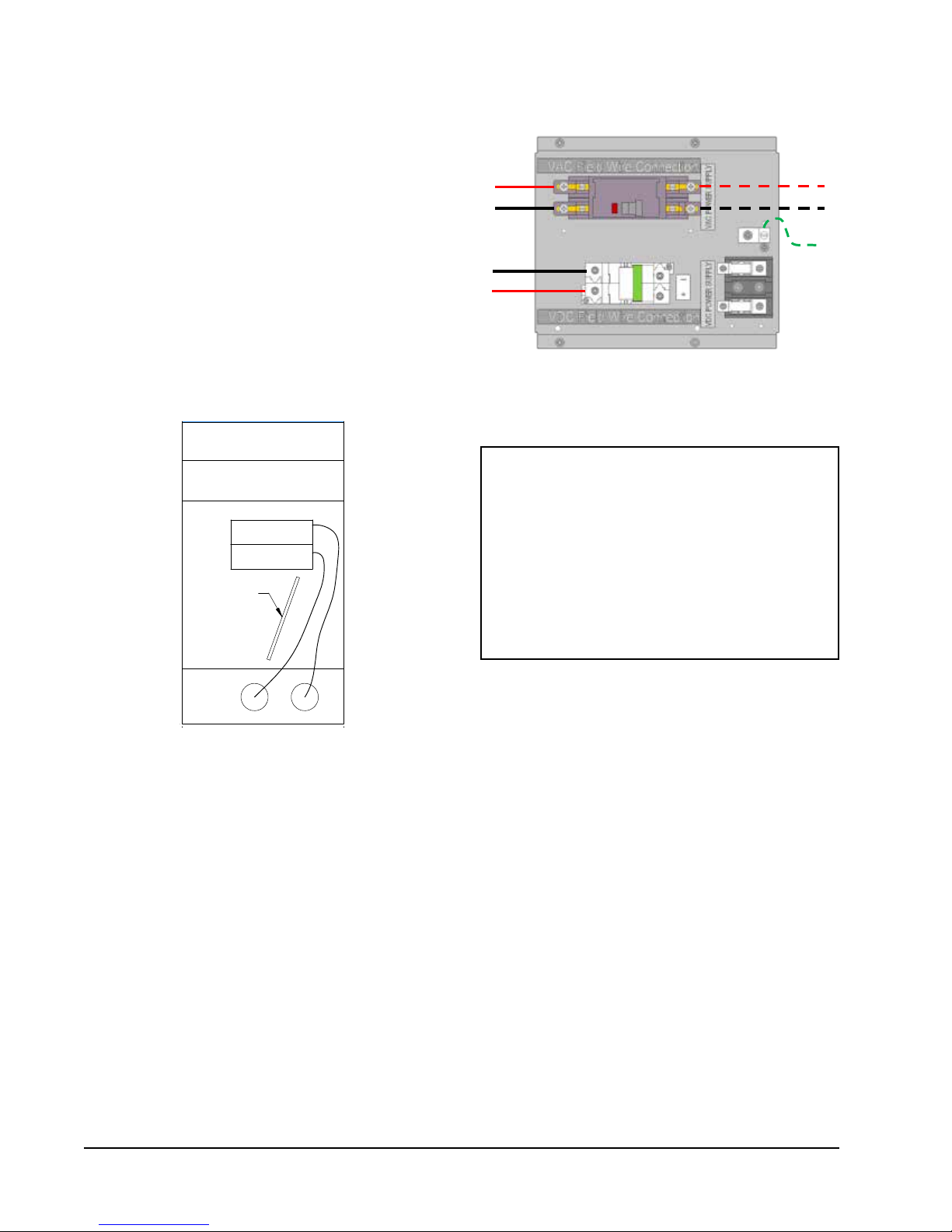
IMPORTANT
230/208V 1 phase and 3 phase equipment use
dual primary voltage transformers. All equipment
leaves the factory wired on 240V tap. It is very
important that the correct voltage tap is used. For
208V operation, reconnect from 240V to 208V
tap (see Figure 1.10). The acceptable operating
voltage range for the 240 and 208V taps are:
240V Tap (253 – 216) and 208 Tap (220 – 197).
Manual 2100-620A
Page 16 of 107
Page 17
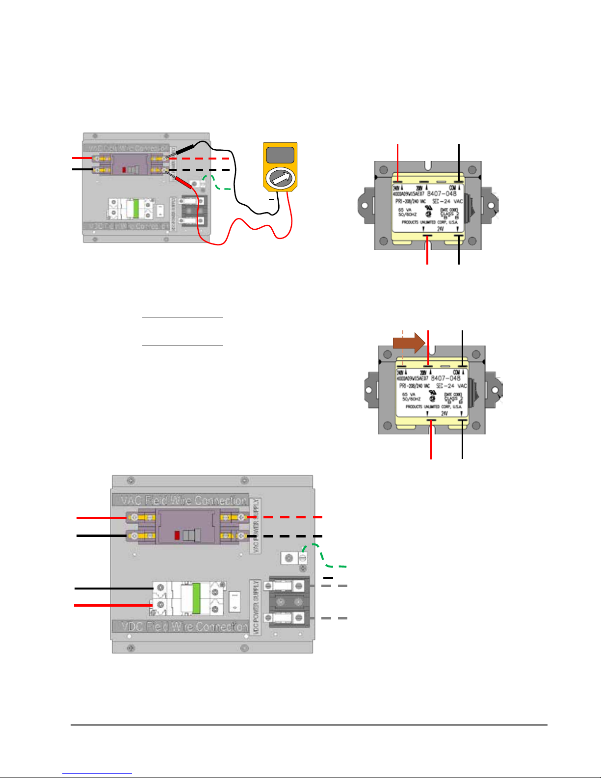
FIGURE 1.10
Adjusting the 230/208 VAC Transformer
It is very important that the correct voltage tap (240V or 208V) is used
1. Verify incoming AC voltage: Multimeter set to VAC
.
Shelter supply breaker in ON position Bard
system breaker in OFF position
230V/208V Single Phase Voltage Range:
197VAC – 253VAC
230V/208V Three Phase Voltage Range:
197VAC – 253VAC
(not shown)
2. If incoming AC voltage is 220VAC or above...
...do not adjust transformer
230VAC
+
3. If incoming AC voltage is below 220VAC...
...shut off AC breaker to unit
and move factory "240V" wire to "208V" terminal
FIGURE 1.11
VDC Supply Wiring Landing Points
.
-
Factory
Wiring
NOTE: Right-hand access model wiring landing points are
shown here; left-hand access models will mirror of
this image.
+
.
Field Wiring
+
Manual 2100-620A
Page 17 of 107
Page 18
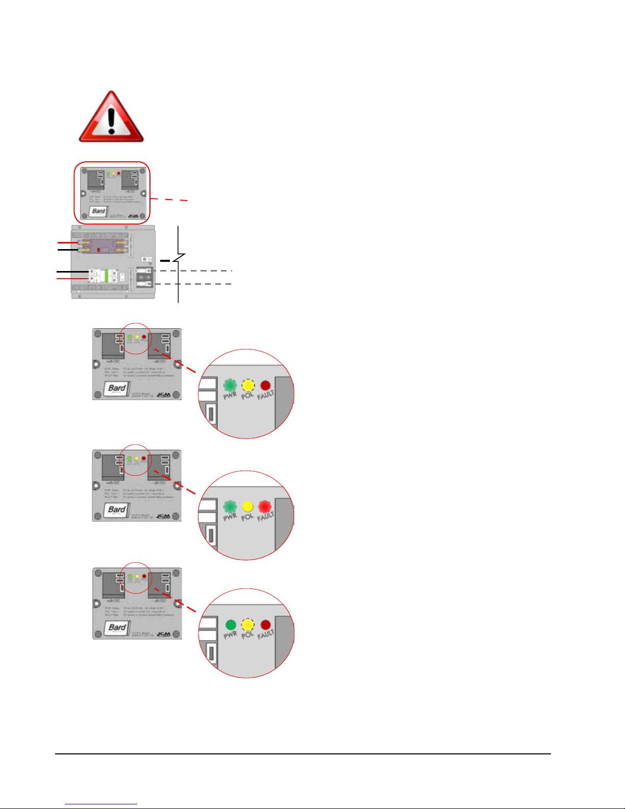
FIGURE 1.12
Bard Polarity-Voltage Monitor
If the VDC wiring is not terminated correctly on the specific polarity-indicated
terminals of the VDC terminal block, the VDC controls and motors will not activate
and the wall-mounted unit will not function.
The Bard Polarity-Voltage Monitor continually monitors for correct polarity and
voltage. If field wiring is connected improperly, or the voltage is outside of the
system parameters, the Polarity-Voltage Monitor will not allow any VDC voltage to
enter the system, protecting the internal controls and equipment.
+
When field wiring is correct in voltage and polarity, the
green power (PWR) LED and yellow polarity (POL) LED
will light, and system will operate normally.
If field wiring is incorrect in polarity, the red FAULT
LED will light, and the monitor will not allow VDC
voltage into the system.
If field wiring is correct in polarity but outside of the
required 40VDC – 56VDC, the green PWR LED will not
illuminate and the monitor not allow VDC voltage into
the system.
If the Polarity-Voltage Monitor is showing a problem with polarity and/or voltage, see pages 67 and 68 of the Service
section of this manual for instructions on checking VDC polarity and verifying incoming VDC voltage.
Manual 2100-620A
Page 18 of 107
Page 19
PRELIMINARY START-UP
RUNNING IN STAND ALONE (ORPHAN) MODE
With both AC and DC breakers turned on, each D-Series wall-mount system has the capability to run without the PLC
controller attached—this feature is called Stand Alone or Orphan Mode, and it basically keeps the shelter between
60°F and 78°F by the use of the factory-installed return air sensor in each wall-mount unit.
During installation, this allows deactivation of one of the two existing, older wall-mount units, while keeping the
shelter cool with the other unit still operating. Once the first of the two Bard wall-mount units is installed, Orphan
Mode can be enabled early in the installation—keeping the climate inside the shelter stable and the installers
comfortable while the remainder of the older equipment is removed and the second Bard wall-mount unit and PLC
controller is installed.
Additionally, should either or both D-Series wall-mount units lose communication with the PLC controller (such as
during maintenance), they will continue to serve the shelter's needs until a repair can be made.
Manual 2100-620A
Page 19 of 107
Page 20
BARD-LINKTM CONTROLLER INSTALLATION
FIGURE 1.13
Typical LC1000/LC1500 Wiring
RJ11 Cable
to Display
48VDC
Power Supply
24VDC
Power
to PLC
Ethernet Cable
PLC Board
Lag Unit
Running Relay
HVAC2 Fail
Alarm Relay
Smoke
Alarm Relay
Hydrogen
Alarm Relay
Generator
Alarm Relay
Web Card
High Temp
Alarm Relay
Low Temp
Alarm Relay
-48VDC
Power Input
24VDC
Hydrogen
Power
Smoke Power
Manual 2100-620A
Page 20 of 107
24VDC
Generator
Alarm Jumper
Remote Temp
Sensor
HVAC1 Fail
Alarm Relay
RS485
Communication
Cable
Alarm Block
Wiring
Page 21

!
WARNING
Electrical shock hazard.
Disconnect both VAC and VDC power supplies
before servicing.
Failure to do so could result in electric shock
or death.
LC1000-100/LC1500-100 CONTROLLER
The Bard-LinkTM LC1000-100 (or LC1500-100)
controller is part of the DC Free Cooling Unit system. It
is used to control two wall-mount air conditioners from
one controller. The microprocessor control provides an
easy-to-read interface with large LCD graphical display.
It provides total redundancy for the structure and
equal wear on both units. The Bard-LinkTM controller is
configured for lead/lag/lead/lag sequence.
Differences Between the LC1000-100 and LC1500-100
There are two separate PLC lead-lag controllers to
choose from and each one serves a specific application.
The LC1000-100 controller comes pre-packaged with
a TEC-EYE hand-held diagnostic tool, one remote
temperature sensor and a pair of communication
EMI filters. This controller is meant for new shelter
construction only, and should never be used in the field
as a retrofit replacement. The LC1500-100 controller
comes pre-packaged with the TEC-EYE hand-held
diagnostic tool, one remote temperature sensor, a pair
of communication EMI filters and a smoke detector.
(The optional 8301-061 hydrogen detector, if ordered
from Bard, is also included with the LC1500-100
controller). The LC1500-100 has an umbilical cord
and 66 punch-down block attached. The LC1500
controller is to be used in all retrofit applications, and
all existing smoke detectors (and hydrogen detectors,
if applicable) are to be removed in lieu of the new
detectors.
Conduit is recommended for all wiring. Use separate
conduits for communication and supply wiring.
1. Mounting the Controller
TM
Because the Bard-Link
temperature sensor as opposed to one located in the
controller box, the controller itself can be installed in
any indoor location that is suitable, preferably at eye
level. Four (4) mounting holes are provided for mounting
to the wall and holes for conduit connections are provided
in both the base, sides and top of the controller. If
installing the LC1500-100, be sure to leave room to
mount the 66 punch-down block (attached with an
umbilical cord) near the controller.
controller utilizes a remote
Manual 2100-620A
Page 21 of 107
Page 22
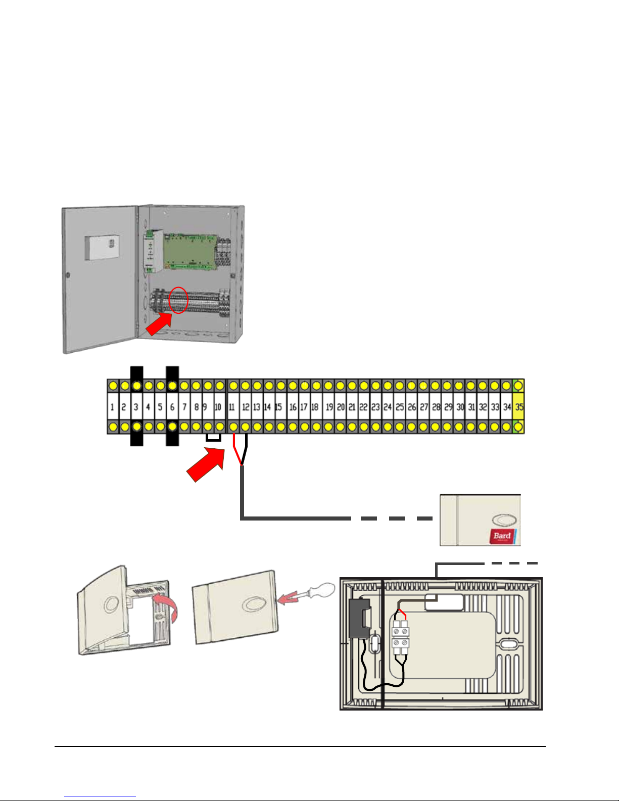
2. Installing Remote Indoor Temperature Sensor(s)
A single remote indoor temperature sensor is included with the controller. This sensor must be installed for proper
operation. Use the included 35' shielded cable to mount the temperature sensor in a location least likely to be
affected by open doors, rack-mounted fans, radiant heat sources, etc. Locating the sensor between both return grilles
is often the best location, but every installation is unique. Location height should be approximately 48" above the
floor. The sensor should be installed on a 4" by 4" junction box to allow for control wire conduit (see Figure 1.14).
For proper operation, the remote indoor temperature sensors must be configured properly with the controller. If only
the single remote indoor temperature sensor supplied with the controller is installed, the configuration setting is
FIGURE 1.14
Remote Indoor Temperature Sensor Installation
1. Connect wires from provided 35' shielded cable to terminals
#11 and #12. The connection is not polarity-sensitive.
2. Connect the other end of the 35' shielded cable to either of
the sensor terminals. These connections are also not polarity
sensitive.
Sensor is best mounted on a junction box, and it is
recommended that the cable be in conduit.
Manual 2100-620A
Page 22 of 107
Page 23

"0". This is the default setting. For information on checking the remote indoor temperature sensor configuration, see
Configuring Additional Remote Indoor Temperature Sensors on page 51.
For unique situations involving temperature flux within the shelter, up to two (2) additional sensors may be
purchased and installed to provide temperature-averaging or highest-temperature protection (see Figure 1.15).
Please see Configuring Additional Remote Indoor Temperature Sensors on page 51 in the Service section of this
manual to set up the additional remotes.
FIGURE 1.15
Additional Remote Temperature Sensor Installation
Up to two (2) additional sensors may be purchased and installed for averaging or highest-temp mode. Use
terminals #13, #14, #15 and #16. These connections are not polarity-sensitive.
Remote Sensor
Optional Additional
Remote Sensor
Optional Additional
Remote Sensor
Manual 2100-620A
Page 23 of 107
Page 24

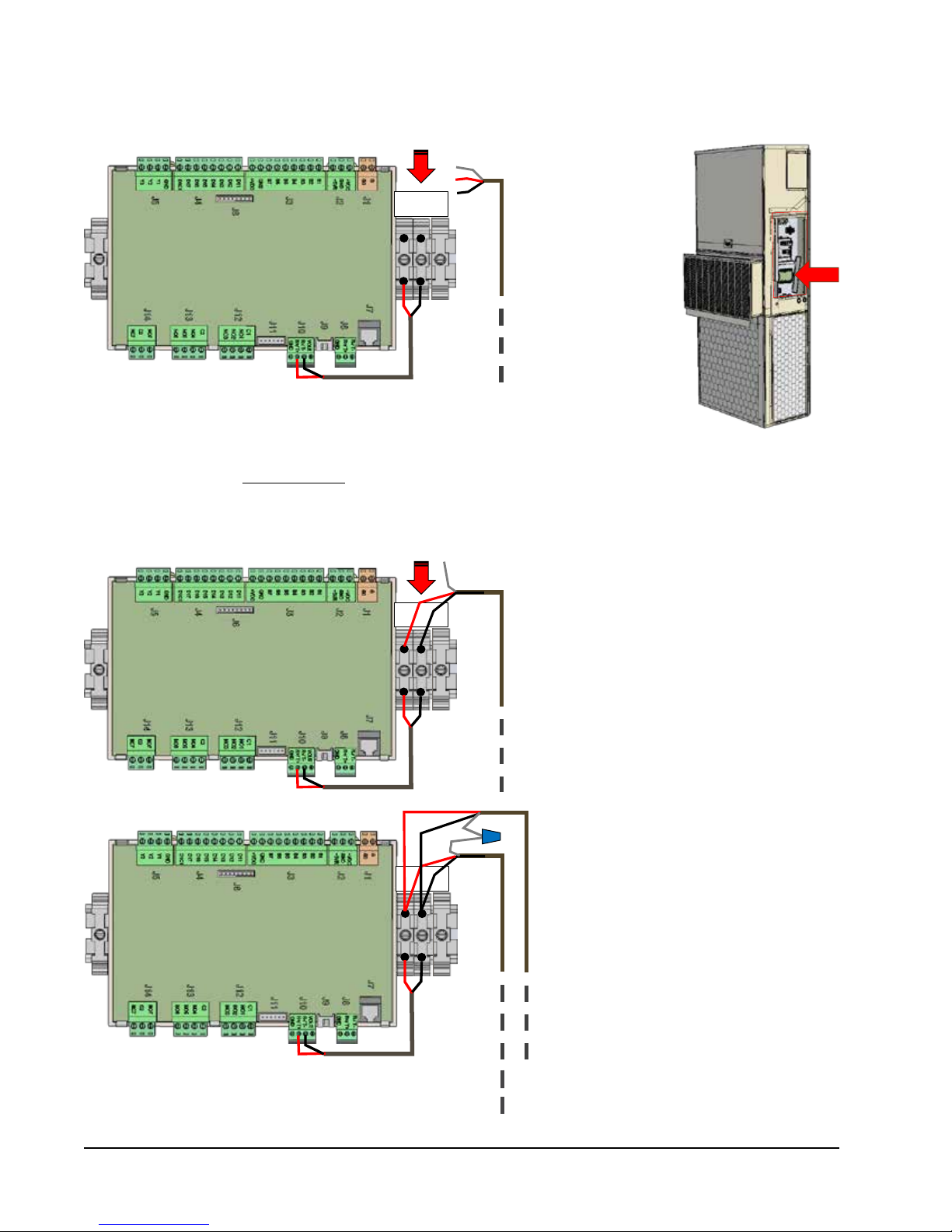
3. Smoke, Hydrogen and Generator Alarms
The LC1500 PLC controller is shipped with a new smoke detector (and optional hydrogen detector if ordered from
Bard) for use in existing shelters. The existing smoke detector (and hydrogen detector, if applicable) should be
removed and disposed of properly. In cases where there are no existing detectors, follow the installation instructions
provided with each detector for location and mounting practices. Both controllers have the capacity to provide power
to a 24VDC smoke detector and a 24VDC hydrogen detector through fused power supply terminals. For proper power
and alarm wiring, review the provided wiring diagrams (see Figures 1.16 and 1.17).
Please note that the provided smoke detector (and hydrogen detector, if applicable) has external testing buttons to
artificially (and temporarily) create an alarm sequence. Additionally, should the desired NC contact closure need to
be changed to the alternative contact closure, please refer to the Service section of this manual to reprogram the
PLC control.
The generator run alarm (if desired) will be signaled through an existing (or field provided) relay attached to the site
generator. The signal from the controller will route through a set of normally closed contacts. Should the generator
start, the contacts will open, triggering the alarm and initiating “Generator Run Mode” (both compressors cannot
operate concurrently). Since some sites do not have a generator present, there is a factory-installed jumper across
terminals #9 and #10. If there is no generator, no action is necessary. If generator run alarm is desired, please
remove the factory-installed jumper and wire per Figure 1.18.
FIGURE 1.16
Power and Signal Connections for Smoke Detector
-24VDC
+24VDC
See Terminal Block Index
on page 33
-24VDC Return Signal
1. Using minimum 18 gauge, non-shielded wire, supply the
new smoke detector with 24VDC from terminals 6 and 7
of the PLC controller.
2. Route a jumper wire from the -24VDC terminal on the
new smoke detector to the common terminal of the onboard relay.
3. From the normally closed contact of the relay, return the
-24VDC signal to terminal #8 of the PLC controller.
Manual 2100-620A
Page 24 of 107
Page 25
NC
COM
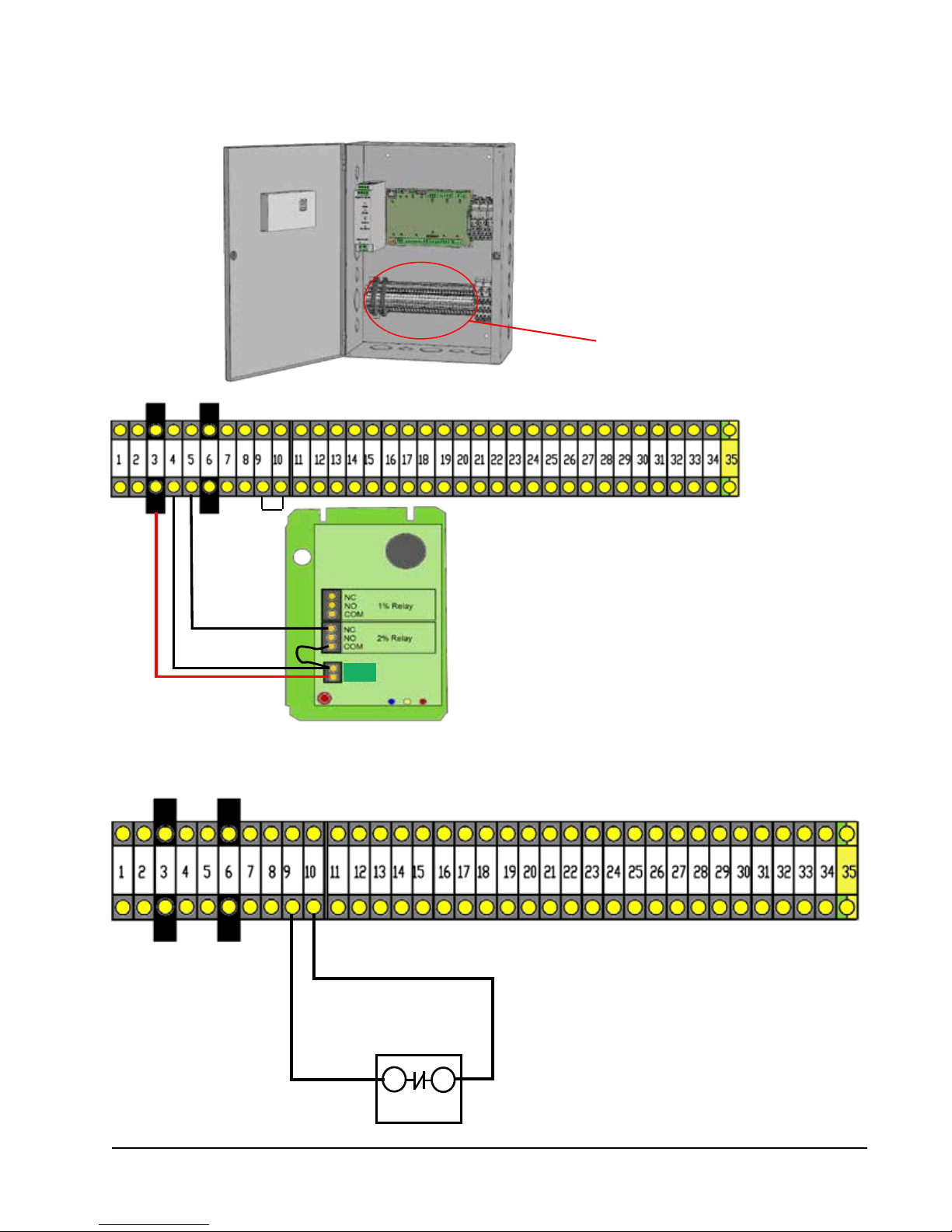
FIGURE 1.17
Power and Signal Connections for Bard-Supplied Hydrogen Detector (If Applicable)
See Terminal Block Index
on page 33
-24VDC
Return
Signal
-24VDC
+24VDC
1. Using minimum 18 gauge, non-shielded wire, supply the
new hydrogen detector with 24VDC from terminals 3 and 4
of the PLC controller.
2. Route a jumper wire from the -24VDC terminal on the new
hydrogen detector to the common terminal of the on-board
2% relay.
-24VDC
+24VDC
3. From the normally closed contact of the relay, return the
-24VDC signal to terminal #5 of the PLC controller.
FIGURE 1.18
LC1000-100 and LC1500-100 Series Generator Run
-24VDC Return Signal
-24VDC
1. If there is a generator on site, remove the factoryinstalled jumper on Terminals #9 and #10. Using
minimum 18 gauge, non-shielded wire, supply the
common terminal on the existing generator relay with
-24VDC from terminal #9 on the PLC controller.
2. From the normally closed contact of the relay, return
the -24VDC signal to terminal #10 of the PLC
controller.
Manual 2100-620A
Page 25 of 107
Page 26

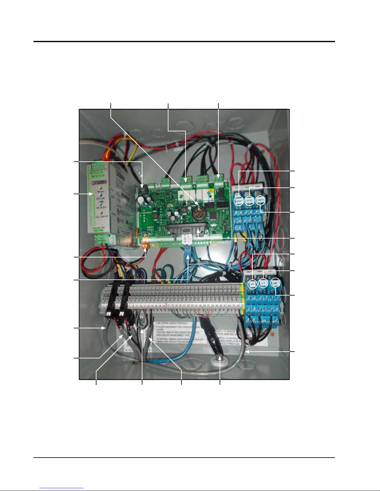
4. Connecting External Alarm Points
Both the LC1000 and LC1500 PLC controls have the capability to provide NC contacts for the following eight (8)
alarms:
• Smoke
• Hydrogen
• Generator
• Lag Unit Run
• High Temp*
• Low Temp*
• HVAC 1 Fail
• HVAC 2 Fail
Before connecting the external alarm wiring, identify the model of the controller (see label inside of controller door).
The LC1000 provides contacts for alarms at the internal terminal block (see Figure 1.19).
The LC1500 PLC control has a pre-installed, pre-wired 66 punch-down block to allow easy connection to these
contacts outside of the controller box (see Figure 1.20).
FIGURE 1.19
LC1000-100 External Alarm Wiring
On the terminal strip of the LC1000 controller, there are eight (8) separate series of normally closed dry contacts for the
following alarm scenarios…
• Smoke
• Hydrogen
• Generator
• Lag Unit Run
• High Temp*
• Low Temp*
• HVAC 1 Fail
• HVAC 2 Fail
* There is no longer any need for the
electro-mechanical coiled-bulb type
thermostats—like the Johnson Penn
A19-Series—for High/Low Temperature
Alarms. Do not install in new sites, and
remove them in retrofit applications.
Lag Unit Run Alarm Common
Lag Unit Run Alarm Contact
Generator Alarm Common
Generator Alarm Contact
Hydrogen Alarm Common
Hydrogen Alarm Contact
Smoke Alarm Common
Smoke Alarm Contact
High Temp Alarm Contact
High Temp Alarm Common
Low Temp Alarm Contact
Low Temp Alarm Common
HVAC 1 Fail Alarm Contact
HVAC 1 Fail Alarm Common
HVAC 2 Fail Alarm Contact
HVAC 2 Fail Alarm Common
Manual 2100-620A
Page 26 of 107
Page 27
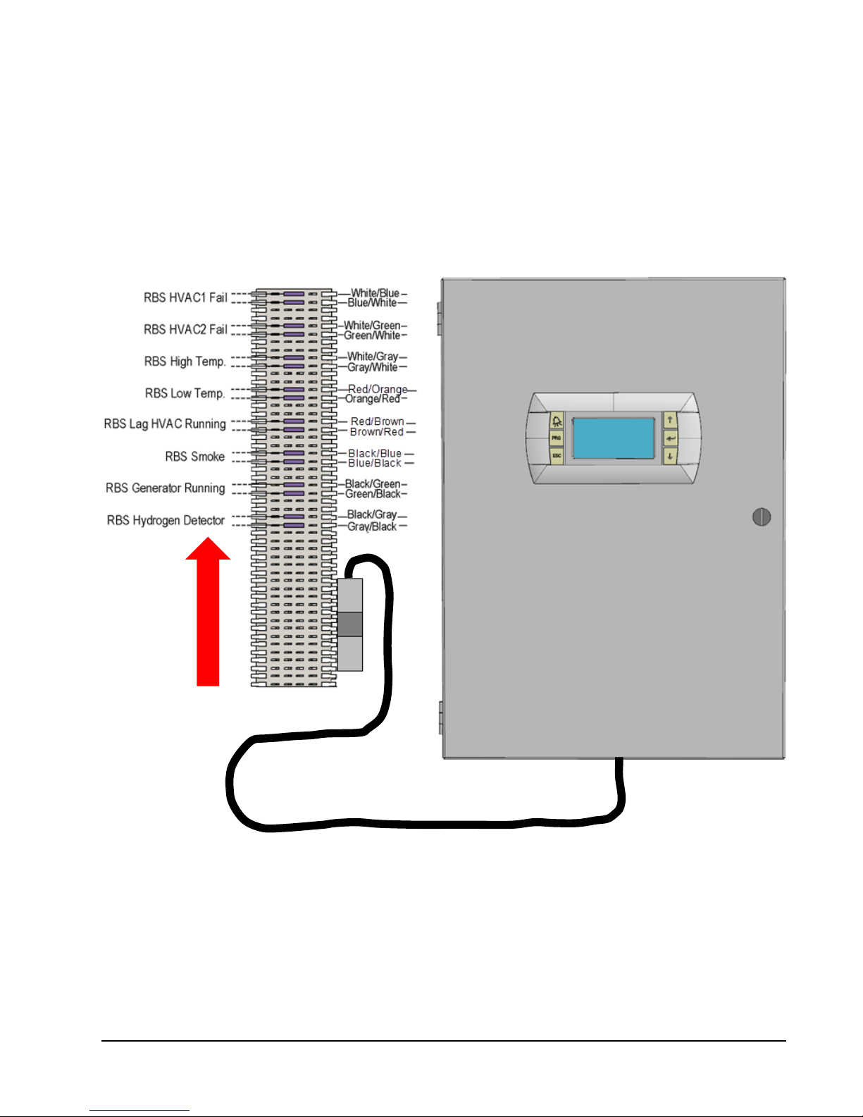
FIGURE 1.20
LC1500-100 External Alarm Wiring
Before connecting the external alarm wiring, identify the model of the controller (see label on inside of controller door. The
connections described below are for the LC1500-100 controller only.
The LC1500-100 has the same eight (8) separate series of normally closed dry contacts as the LC1000-100, but has a
prewired 66 punch-down block to make external connections easier.
• Smoke
• Hydrogen
• Generator
• Lag Unit Run
• High Temp*
• Low Temp*
• HVAC 1 Fail
• HVAC 2 Fail
Field wiring for alarms
48” umbilical cord allows for mounting the 66 punch-down
block to either side, top or bottom of PLC controller cox.
Bridge clips have been inserted for convenience.
* There is no longer any need for the electro-mechanical coiled-bulb type thermostats—like the Johnson Penn A19-
Series—for High/Low Temperature Alarms. Do not install in new sites, and remove them in retrofit applications.
Manual 2100-620A
Page 27 of 107
Page 28
5. Communication Wiring
Connect the communication wiring from the two wall-mount units to the controller in the manner shown in Figure
1.21. The communication wire should be 2-wire, 18 gauge shielded cable with drain. Any color can be used. Be
sure to match "+" and "-" symbols on controller terminal blocks to prewired unit control terminal block (see Figures
1.23 and 1.24 on pages 30 and 31). Attach communication wire filters as shown below in Figure 1.22. Use separate
conduits for communication and supply wiring.
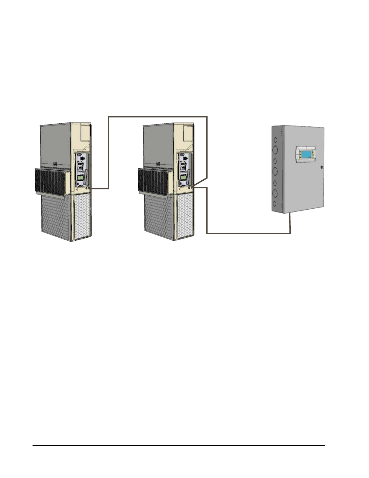
FIGURE 1.21
Communication Wiring
D-Series
Wall-Mount Unit
D-Series
Wall-Mount Unit
Bard-LinkTM
Controller
Manual 2100-620A
Page 28 of 107
Page 29
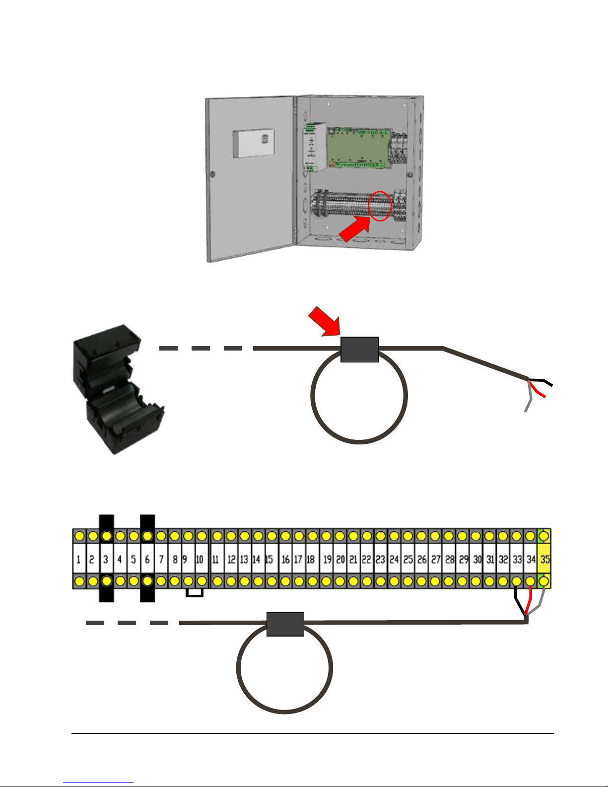
FIGURE 1.22
- +
G
Communication Wiring: Termination at the Controller
1. Using the field-provided shielded cable, make a small service loop after entering the controller and attach the provided
EMI filter at the intersection of the loop.
2. Connect one wire to terminal #33 (negative), the other wire to terminal #34 (positive) and the drain wire to ground
terminal #35.
To Wall-Mount Unit 1
Control Board RS485
Manual 2100-620A
Page 29 of 107
Page 30
RS485
R+T+ / R-T-
FIGURE 1.23
RS485
R+T+ / R-T-
Communication Wiring: Termination at the First Wall-Mount Unit
RS485
R+T+ / R-T-
Wall-Mount Unit 1
Control Board
1. From the controller, extend the shielded cable through a separate conduit
and route to the provided terminal block next to the wall-mount control
board.
Note that the terminal block label is clearly marked “+” and “-”. These
connections are polarity-sensitive. Two-wire communication from control
board is prewired to terminal block. Make sure to match "+" and "-"
symbols on controller terminal blocks.
From LC1000-100
or LC1500-100
Controller
2. Connect the wires matching the terminal
designations (+/-) of the controller terminals.
Leave the drain wire loose.
Wall-Mount Unit 1
Control Board
From LC1000-100
or LC1500-100
Controller
Wall-Mount Unit 1
Control Board
Manual 2100-620A
Page 30 of 107
3. Connect another cable in a similar
fashion (“daisy chain”) to route in
conduit to the second wall-mount unit.
Connect both drain wires with wire nut.
From LC1000-100
or LC1500-100
Controller
To Wall-Mount Unit 2
Control Board RS485
Page 31

FIGURE 1.24
RS485
R+T+ / R-T-
Communication Wiring: Termination at the Second Wall-Mount Unit
RS485
R+T+ / R-T-
Wall-Mount Unit 2
Control Board
1. Route the cable from the first wall-mount unit to the
terminal block of the second wall-mount unit. Make a
small service loop and attach EMI filter as shown.
Wall-Mount Unit 2
Control Board
From Wall-Mount
Unit 1 RS485
2. Connect the wires matching the terminal
designations (+/-) of the controller terminals.
Cap the loose drain with a wire nut or
electrical tape.
From Wall-Mount
Unit 1 RS485
Manual 2100-620A
Page 31 of 107
Page 32

6. Supply Wiring
The LC1000-100/LC1500-100 controller is powered by -48VDC from the shelter. A field-supplied 5 amp DC circuit
breaker is required. Field-supplied supply wiring should be minimum 16 guage, maximum 14 guage (see Figure
1.25). A reliable earth ground must be connected in addition to any grounding from conduit. Grounding posts are
included with the controller for this purpose; install as shown in Figure 1.26. Failing to ground the controller box
properly could result in damage to the equipment.
FIGURE 1.25
Bard-LinkTM LC1000-100/LC1500-100 Controller Circuit Install
The Bard-LinkTM controller requires a separate -48VDC power supply, an
additional 5-amp DC breaker (field supplied) and minimum 16 gauge
supply wire.
-48VDC termination at controller: Bring the -48VDC power supply wires
through conduit to the controller box. Land the positive (+) 48VDC wire
to terminal #1 and the negative (-) 48VDC wire to terminal #2.
NOTE: If the DC wiring is not terminated correctly on the
specific polarity-indicated terminals of the PLC block, the
PLC controller will not activate and will not function. Verify
polarity of connections and wait to initialize controller until
"startup procedures."
Manual 2100-620A
Page 32 of 107
FIGURE 1.26
Controller Grounding Posts
A reliable earth ground must be connected in
addition to any grounding from conduit. Attach
earth ground to dedicated lugs on side of controller
box. Failing to ground the controller box properly
could result in damage to the equipment.
Page 33

TABLE 1.2
Terminal Block Index
Wire
TB#
Mark
1 48+ 48+ VDC Input
2 48- 48- VDC Input
3 24+ 24+VDC Input – Hydrogen
4 24- 24-VDC Input – Hydrogen
5 HA2 HA2 – Hydrogen ALR Signal Return
6 24+ 24+ VDC Input – Smoke
7 24- 24- VDC Input – Smoke
8 SA2 SA2 – Smoke ALR Signal Return
9 24- 24- VDC
10 GA2 GA2 – Generator ALR Signal Return
11 B1 Indoor Remote Sensor
12 GND GND
13 B2 Spare Remote Sensor 1
14 GND GND
15 B3 Spare Remote Sensor 2
16 GND GND
17 S24 Smoke ALR Relay Contact
18 S21 Smoke ALR Relay Contact Common
19 H24 Hydrogen ALR Relay Contact
20 H21 Hydrogen ALR Relay Contact Common
21 G24 Generator ALR Relay Contact
22 G21 Generator ALR Relay Contact Common
23 NO1 Lag Unit Run Relay Contact
24 C1 Lag Unit Run Relay Contact Common
25 HT12 High Temp ALR Relay Contact
26 HT11 High Temp ALR Relay Contact Common
27 LT12 Low Temp ALR Relay Contact
28 LT11 Low Temp ALR Relay Contact Common
29 HF12 HVAC1 Fail ALR Relay Contact
30 HF11 HVAC1 Fail ALR Relay Contact Common
31 NO7 HVAC2 Fail ALR Relay Contact
32 C3 HVAC2 Fail ALR Relay Contact Common
33 R- RS485 RX-/TX-
34 R+ RS485 RX+/TX+
35 GND Drain Shield Grounding Wire
Description NO NC
Manual 2100-620A
Page 33 of 107
Page 34

BLACK/RED
MIS-3632
TB#Wire
Mark Descripti on NO NC
1 48+ 48+VDC Input
2 48- 48- VDC Input
3 24+ 24+VDC Input - hydrogen
4 24- 24- VDC Input - hydrogen
5 HA2 HA2 - Hydrogen ALR signal return
6 24+ 24+ VDC Input - Smoke
7 24- 24- VDC Input - Smoke
8 SA2 SA2 - Smoke ALR Signalr eturn
9 24- 24- VDC
10 GA2 GA2 - Generator ALR signal return
11 B1 Indoor remote sensor
12 GND GND
13 B2 Spar e Remote sensor 1
14 GND GND
15 B3 Spar e Remote sensor 2
16 GND GND
17 S24 Smoke ALR relay contact
18 S21 Smoke ALR relay contact c ommon
19 H24 Hydrogen A LRrelay c ontact
20 H21 Hydrogen A LRrelay c ontact common
21 G24 Generator ALR relay contact
22 G21 Generator ALR relay contac t common
23
NO1 Lag un
it run relay contact
24 C1 Lag unit run relay contact c ommon
25 HT12 High Temp A LRrelay c ontact
26 HT11 High Temp A LRrelay c ontact common
27 LT12 Low Temp ALR relay contact
28 LT11 Low Temp ALR relay contact c ommon
29 HF12 HVAC1 Fail ALR relay contact
30 HF11 HVAC1 Fail ALR relay contact common
31 NO7 HVAC2 Fail ALR relay contact
32 C3 HVAC2 Fail ALR relay contact c ommon
33 R- RS485 RX- / TX-
34 R+ RS485 RX+ / TX+
35 GND Drain Shield grounding w ire
RED/BLACK
BLACK/RED
BLACK/RED
BLACK/RED
FIGURE 1.27
LC1000/LC1500 Wiring Diagram
GND
VOUT
RX-TX-
RX+TX+
GND
RX-TX-
RX+TX+
C1
C2
N02
N03
N01
N05
N04
N06
N07
C3
NC7
A1
A2 A1 A2 A1
RELAY
SMK
RELAY
HYD
RELAY
GEN
A2
24VDC
48VDC
BLUE
YELLOW
+
- +
BLACK
RED
RED/BLACK
BLACK/RED
G
G0
B1
B2B3B4
B5
B6
B7
GND
+VDC
+5 VREF
RED
RED
RED
GREEN
GND
D14
D11
D12
D13
+VDC
BLUE/BLACK
BLUE/BLACK
BLUE/BLACK
BLACK/WHITE
BLACK/WHITE
BLACK/WHITE
TO HT 11
TO LT 12
TO HT 12
12345 6 7 8 9 10 11 12 13 14 15 16 171 8 19 20 21 22 23 24 25 26 2728 29 30 31 32 3334 35
JUMPER
22
12
12
22
24
14
14
24
2111
11
21
Y2
Y3
Y1
D16
D17
D15
DIC1
GND
BLACK/WHITE
BLUE/BLACK
BLUE/BLACK
BLUE/BLACK
NC
22
12
NO
14
24
COM
11
21
BLACK
BLACK
BLACK
BLACK
BLACK
BLACK
BLACK
BLACK
BLACK
TO LT 11
TO HF 12
TO HF 11
A1 A2 A1 A1 A2
A2
RELAY
HT
RELAY
LT
RELAY
HF
12
142124
11
12
22
22
24
14
21
11
NC
2212
NO
2414
COM
2111
TO TB 26
TO TB 25
TO TB 28
TO TB 30
TO TB 29
TO TB 27
MIS-3632
Manual 2100-620A
Page 34 of 107
Page 35

RBS HVAC 1
WHITE/GRAY
GREEN/BLACK
BROWN/RED
RED/BROWN
BLUE/WHITE
WHITE/GREEN
GREEN/WHITE
WHITE/BLUE
GRAY/WHITE
RED/ORANGE
ORANGE/RED
ALARM
RBS HVAC 2
ALARM
RBS HIGH TEMP.
FIGURE 1.28
LC1500-100 Punch-Down Block Wiring
A
RBS LOW TEMP.
RBS LAG HVAC
RUNNING
RBS SMOKE
RBS GENERATOR
RUNNING
RBS HYDROGEN
DETECTOR
TO TERMINAL BLOCKS
JUMPER CONNECTED TO
TERMINAL PAIR TO PROVIDE
A DEMARCATION POINT
JUMPER CONNECTED TO
TERMINAL PAIR TO PROVIDE
A DEMARCATION POINT
RED/ORANGE
ORANGE/RED
DETAIL: A
WHITE/GREEN
GREEN/WHITE
JUMPER
BLACK/BLUE
BLUE/BLACK
BLACK/GRAY
GRAY/BLACK
BLACK/GREEN
GREEN/BLACK
RED/BROWN
BROWN/RED
WHITE/GRAY
GRAY/WHITE
WHITE/BLUE
BLUE/WHITE
1 2 3 4 5 6 7 8 9 10 11 12 13 14 15 16 17 18 19 20 21 22 23 24 25 26 27 28 29 30 31 32 33 34 35
DETAIL: A
MIS-3631
Manual 2100-620A
Page 35 of 107
Page 36

SYSTEM START-UP
FIGURE 1.29
Bard-LinkTM Controller Display
ALARM KEY
MENU KEY
ESCAPE KEY
ALARM KEY
Allows viewing of active alarms
Silences audible alarms
Resets active alarms
MENU KEY
Allows entry to Main Menu
ESCAPE KEY
Returns to previous menu level
Cancels a changed entry
UP KEY
Steps to next screen in the display menu
Changes (increases) the value of a modifiable field
ENTER KEY
Accepts current value of a modifiable field
Advances cursor
DOWN KEY
Steps back to previous screen in the display menu
Changes (decreases) the value of a modifiable field
1. Set Controller Date and Time
1) Shut down all breakers to system, both wall-
TM
mount units and the Bard-Link
controller.
2) Restore power (both AC and DC) to the two
wall-mount units.
TM
3) Turn on power to the Bard-Link
controller.
There is a forty (40) second delay prior to
any function (other than display backlight)
becoming active. The Status screen is the
default screen when the controller has power.
4) Access the Main Menu by pressing the Menu
key.
5) Press the UP or DOWN keys to scroll to the
Clock/Scheduler menu. Press the ENTER key
(see Figure 1.30).
6)
Move the cursor to the Date line by pressing
the ENTER key. Press the UP or DOWN keys to
change the date. The Day line will automatically
change when the date has been altered.
7) Press the ENTER key to move to the Hour line.
Press the UP or DOWN keys to change the
time. Press the ENTER key to set the time.
8) Press the ESCAPE several times to return to
the Status menu.
UP KEY
ENTER KEY
DOWN KEY
2. Verify Communication to Units
Check controller display to see that both units are
"ON-LINE" (see Figure 1.31). This typically takes 3-4
minutes after controller is powered.
FIGURE 1.30
Clock/Scheduler Menu
FIGURE 1.31
Status Display Showing Units "Online"
For shelter applications involving only a single
DUAL-TEC™ DC Free Cooling Unit, see page 38.
Manual 2100-620A
Page 36 of 107
Page 37

3. Conduct Run Test
Execute a run test on each unit to verify the equipment
is functioning correctly.
On Bard-Link
TM
controller, navigate to the Run Test
screen (Figure 1.32).
FIGURE 1.32
Executing Run Test
1) From the Main Menu screen, press the UP
or DOWN key to get to Technician menu, hit
ENTER key. (If not already on Main Menu
screen, press MENU key to get to Main Menu.)
2) Use Up or DOWN key to get to Service menu,
press ENTER key.
3) Use Up or DOWN key to get to Control menu,
press ENTER key.
4) Cursor will be flashing in upper left corner of
screen. Press ENTER key to scroll to U1 Run
Test.
5) Press UP key to change 'No" on screen to
"Yes". Unit 1 will begin the run test.
Note: While initiating the run test on each
unit, use this opportunity to appropriately label
each system as “Unit 1” or “Unit 2.”
6) After the Unit 1 run test ends, press ENTER
key to scroll to U2 Run Test.
7) Press UP key to change 'No" on screen to
"Yes". Unit 2 will begin the run test.
Run Test Approximate Timings (in Minutes)
Blower On: 0:00
Damper Open: 0:00 – 2:40
Closed: 2:41 – 4:57
Compressor On: 4:58
Off: 6:00
Heat On: 6:01
Off: 7:10
Blower Off: 8:19
4. Completing Installation
Once all the installation steps have been completed, and system verification and run test results were satisfactory,
TM
the installation can now be considered “complete.” The Bard-Link
PLC lead/lag controller has been pre-
programmed with what is widely considered to be the most efficient operating parameters—see Table 1.3 on page
40. Further information on exact sequence of operation and advanced programming changes can be found in the
Service section of this manual.
Cool Weather Operation (Free Cooling Available):
Stage 1 Cooling 78°F – Lead unit free-cooling damper opens (Setpoint + Cooling Stage 1 Differential)
Stage 2 Cooling 79°F – Lag unit free-cooling damper opens (+ Cooling Stage 2 Differential)
Stage 3 Cooling 81°F – Lead unit compressor, damper will stay open if conditions are conducive for free cooling
(+ Cooling Stage 3 Differential)
Stage 4 Cooling 83°F – Lag unit compressor, damper will stay open if conditions are conducive for free cooling
(+ Cooling Stage 4 Differential)
Hi-Temp Alarm #1 85°F
Hi-Temp Alarm #2 90°F – Emergency ventilation initiates, both dampers open, both blowers run
75°F – All cooling stops, blowers stop (Setpoint -2°F)
Stage 1 Heating 58°F – Lead unit heat strip activates
Stage 2 Heating 56°F – Lag unit heat strip activates
Low-Temp Alarm 45°F
62°F – All heating stops, blowers stop
Warm Weather Operation (No Free Cooling Available):
Stage 1 Cooling 78°F – Lead unit compressor (Setpoint + Cooling Stage 1 Differential)
Stage 2 Cooling 83°F – Lag unit compressor (+ Cooling Stage 2, Stage 3 and Stage 4 Differentials)
Hi-Temp Alarm #1 85°F
Hi-Temp Alarm #2 90°F – Emergency ventilation initiates, both dampers open, both blowers run
75°F – All cooling stops, blowers stop (Setpoint -2°F)
Manual 2100-620A
Page 37 of 107
Page 38

TABLE 1.3
Controller Default Settings
Description Default Setpoint
Temperature at local remote
(main) sensor
Temperature Setpoint 77°F
Heating Setpoint 60°F
Temperature High Limit –
Level 1
Temperature High Limit –
Level 2 (High Temp Alarm)
Temperature Low Limit 45°F
Cooling Stage 1 Differential 1°F
Cooling Stage 2 Differential 1°F
Cooling Stage 3 Differential 2°F
Cooling Stage 4 Differential 2°F
Heating Stage 1 Differential 2°F
Heating Stage 2 Differential 2°F
Minimum Compressor Run
Time
Minimum Compressor Off
Time
Comfort Mode Setpoint 72°F
Comfort Mode Operation
Time
DC Freecooling Setpoint 55°F
Lead/Lag Changeover Time
(Rotation)
Temperature Units °F
--
85°F
90°F
5 Minutes
2 Minutes
60 Minutes
1
WEB CARD COMMUNICATION BOARD
Note: A web card communications board allows remote
access, via Ethernet, to all functions of the controller
system. This is the same as if one was in the building
where the controller system is physically installed.
TM
Connect the Bard-Link
LC1000-100 or LC1500-100
controller Ethernet port to the existing Ethernet card in
the shelter (if applicable) using CAT 6 Ethernet cable.
TEC-EYE HAND-HELD DIAGNOSTIC
TOOL
The TEC-EYE hand-held diagnostic tool is included
with each Bard-Link
leaving the jobsite, make sure to store the TEC-EYE
hand-held diagnostic tool inside the shelter, preferably
close to the Bard-LinkTM PLC controller. The TEC-EYE
has integrated magnets on the back of the tool, so
it can even be attached to the front, sides, bottom,
or top of the PLC control box. Although the tool is
not necessary for installation purposes, the “TECEYE” will be very valuable to technicians performing
maintenance or repair procedures. Do not let the TECEYE leave the shelter.
TM
PLC lead/lag controller. Before
SINGLE HVAC UNIT SHELTERS ONLY
In certain applications, only one wall-mount unit
will be installed on a particular shelter. This may be
desirable due to space considerations, load specifics or
other non-typical situations. If only one Dual-Tec™ unit
will be connected to the Bard-Link
please follow the steps below to allow operation without
nuisance alarms.
1. Go to the Setpoints menu on Bard-Link
controller; press ENTER key.
2. Press DOWN arrow key seven (7) times to reach
"Number of Units" screen. Press ENTER key to
cause cursor to flash.
3. Press DOWN arrow key to change value to "1".
4. Cycle power to Bard-Link
TM
PLC controller,
TM
PLC controller.
TM
PLC
SPECIAL OPERATIONAL FORMAT: COASTAL MODE
In certain locations (geographical or situational), outdoor air used for “free cooling” can be corrosive or have
other non-desirable qualities. Although the DC-FCU system was meant to take full advantage of outdoor air
cooling, Bard Manufacturing has included a special operations format within the programming that will not
allow any damper activity for “free cooling.” By enabling the “Coastal Mode” function, the DC-FCU system
will only cool through mechanical (compressor) means. However, the damper will still open under emergency
conditions (high temperature #2 alarm or hydrogen alarm, if installed) to flood the room with outdoor air, and
the damper will allow for “free cooling” under a power loss situation when the compressor cannot function.
This mode is set by the model and serial number—completely automatic—and cannot be overridden locally.
Manual 2100-620A
Page 38 of 107
Page 39

SECTION 2:
SERVICE
INSTRUCTIONS
Manual 2100-620A
Page 39 of 107
Page 40

GENERAL REFRIGERANT INFORMATION
REMEMBER: When adding R-410A refrigerant, it must
come out of the charging cylinder/tank as a liquid to
avoid any fractionation and to insure optimal system
performance. Refer to instructions for the cylinder that
These units require R-410A refrigerant and
polyol ester oil.
GENERAL
1. Use separate service equipment to avoid cross
contamination of oil and refrigerants.
2. Use recovery equipment rated for R-410A
refrigerant.
3. Use manifold gauges rated for R-410A (800
psi/250 psi low).
4. R-410A is a binary blend of HFC-32 and HFC-
125.
5. R-410A is nearly azeotropic—similar to R-22 and
R-12. Although nearly azeotropic, charge with
liquid refrigerant.
6. R-410A operates at 40-70% higher pressure than
R-22, and systems designed for R-22 cannot
withstand this higher pressure.
7. R-410A has an ozone depletion potential of zero,
but must be reclaimed due to its global warming
potential.
8. R-410A compressors use polyol ester oil.
9. Polyol ester oil is hygroscopic; it will rapidly absorb
moisture and strongly hold this moisture in the oil.
10. A liquid line dryer must be used—even a deep
vacuum will not separate moisture from the oil.
11. Limit atmospheric exposure to 15 minutes.
12. If compressor removal is necessary, always plug
compressor immediately after removal. Purge with
small amount of nitrogen when inserting plugs.
TOPPING OFF SYSTEM CHARGE
If a leak has occurred in the system, Bard
Manufacturing recommends reclaiming, evacuating
(see criteria above) and charging to the nameplate
charge. If done correctly, topping off the system charge
can be done without problems.
With R-410A, there are no significant changes in the
refrigerant composition during multiple leaks and
recharges. R-410A refrigerant is close to being an
azeotropic blend (it behaves like a pure compound or
single component refrigerant). The remaining refrigerant
charge in the system may be used after leaks have
occurred. “Top-off” the charge by utilizing the pressure
charts on the inner control panel cover as a guideline.
is being utilized for proper method of liquid extraction.
SAFETY PRACTICES
1. Never mix R-410A with other refrigerants.
2. Use gloves and safety glasses. Polyol ester oils can
be irritating to the skin, and liquid refrigerant will
freeze the skin.
3. Never use air and R-410A to leak check; the
mixture may become flammable.
4. Do not inhale R-410A—the vapor attacks
the nervous system, creating dizziness, loss
of coordination and slurred speech. Cardiac
irregularities, unconsciousness and ultimately
death can result from breathing this concentration.
5. Do not burn R-410A. This decomposition produces
hazardous vapors. Evacuate the area if exposed.
6. Use only cylinders rated DOT4BA/4BW 400.
7. Never fill cylinders over 80% of total capacity.
8. Store cylinders in a cool area, out of direct
sunlight.
9. Never heat cylinders above 125°F.
10. Never trap liquid R-410A in manifold sets, gauge
lines or cylinders. R-410A expands significantly at
warmer temperatures. Once a cylinder or line is full
of liquid, any further rise in temperature will cause
it to burst.
R410-A REFRIGERANT CHARGE
This unit was charged at the factory with the quantity
of refrigerant listed on the serial plate. AHRI capacity
and efficiency ratings were determined by testing with
this refrigerant charge quantity.
The pressure table found on the following page
shows nominal pressures for the units. Since many
installation specific situations can affect the pressure
readings, this information should only be used by
certified technicians as a guide for evaluating proper
system performance. They shall not be used to adjust
charge. If charge is in doubt, reclaim, evacuate and
recharge the unit to the serial plate charge.
Manual 2100-620A
Page 40 of 107
Page 41

Model
D36A
D42A
D48A
D60A
Return Air
Temperature
75° DB
62° WB
80° DB
67° WB
85° DB
72° WB
75° DB
62° WB
80° DB
67° WB
85° DB
72° WB
75° DB
62° WB
80° DB
67° WB
85° DB
72° WB
75° DB
62° WB
80° DB
67° WB
85° DB
72° WB
TABLE 2.1
Nominal Pressures: Models D36A, D42A, D48A, D60A
Air Temperature Entering Outdoor Coil, Degree °F
Pressure
Low Side
High Side
Low Side
High Side
Low Side
High Side
Low Side
High Side
Low Side
High Side
Low Side
High Side
Low Side
High Side
Low Side
High Side
Low Side
High Side
Low Side
High Side
Low Side
High Side
Low Side
High Side
75 80 85 90 95 100 105 110 115 120
133
135
137
138
139
141
313
142
321
147
332
131
315
140
323
145
334
133
325
142
333
147
345
129
353
138
362
143
375
327
144
335
149
347
132
331
141
339
146
351
136
341
145
350
150
362
130
362
139
371
144
384
342
146
351
151
363
134
348
143
357
148
369
137
360
147
369
152
382
132
374
141
384
146
397
361
148
370
153
383
136
368
145
377
150
390
139
379
149
389
154
403
133
390
142
400
147
414
382
149
392
154
406
137
388
147
398
152
412
141
401
151
411
156
425
134
410
143
420
148
435
406
151
416
156
431
139
410
149
421
154
436
142
424
152
435
157
450
136
432
145
443
150
459
143
432
153
443
158
459
142
435
152
446
157
462
144
449
154
461
159
477
137
458
146
470
151
486
145
461
155
473
160
490
144
461
154
473
159
490
145
477
155
489
160
506
137
488
147
501
152
519
147
492
157
505
162
523
146
489
156
502
161
520
147
505
157
518
162
536
139
522
149
535
154
554
Part No. Ratings
149
527
8552-079
159
540
8552-005
165
559
149
520
8552-079
159
533
8552-005
165
552
148
535
8552-089
158
549
8552-005
164
568
140
559
8552-058
150
573
8552-005
155
593
Capacitors
1 Ø, 240V
45+10/370
3 Ø, 240V
10/370
1 Ø, 240V
45+10/370
3 Ø, 240V
10/370
1 Ø, 240V
70+10/370
3 Ø, 240V
10/370
1 Ø, 240V
80+10/440
3 Ø, 240V
10/370
Low Side Pressure ±4 PSIG
High Side Pressure ±10PSIG
FIGURE 2.1
Refrigerant Sight Glass
The refrigerant sight glass installed in this unit is not a
charging indicator. Use only universally recommended
practices of charging: superheat, subcooling,and preferably,
weighing in the correct charge. The sight glass is for
moisture reference only.
Manual 2100-620A
Page 41 of 107
Page 42

SEQUENCE OF OPERATION
D-SERIES WALL-MOUNT UNIT
SEQUENCE OF OPERATION
Overview
This product is designed to function like a typical
Telecom air conditioning system with an outdoor aircooling damper. However, the DC-FCU system does
have some special features, like a PLC control which
allows for advanced alarming and a “DC Free Cooling”
feature that allows for forced emergency ventilated
cooling anytime “shore power” VAC power from the
utility company is lost. The internal controls within
this unit automatically recognize a loss of shore power,
energizing the indoor blower motor and powering the
actuator to open the damper to bring in outdoor air.
The power utilized during this time is the stored battery
power from the equipment shelter.
Indoor Blower
The indoor blower is a 48VDC motor, completely
separate from the VAC circuit(s). For the blower to
activate, two (2) separate actions must take place:
1. 24VDC from terminal N07 (Blower Motor Start
Relay)
2. 0-10VDC signal from terminal Y1 (Speed Voltage)
While the 24VDC from N07 will always stay the
same, the 0-10VDC signal from terminal Y1 will vary
depending upon the mode. See Table 2.2.
DC Free Cooling Damper
This controller is enabled for dewpoint control,
specifically examining the combination of temperature
and relative humidity to determine the proper control
of cooling. This calculated dewpoint property then
determines the proper mode of cooling—Outdoor Air,
Mechanical Cooling, or both. To signal the 24VDC
damper actuator to open, a 2-10VDC signal must
come from the Y2 terminal. Additionally, while other
modes get only a single speed from the indoor blower,
free cooling mode will get two (2): one for outdoor air
temperature above 40°F (faster), and another for those
below 40°F (slower). See Table 2.2.
Cooling Call
When a call for cooling generates from the controller,
the system will first determine which mode of cooling
to employ based on the outdoor temperature, the
outdoor humidity, and the indoor temperature.
• If the outdoor temperature and humidity ratio are
conducive to free cooling, the control board will
send:
1. 2-10VDC Signal from Y2 (Damper Signal)
- Modulates damper to achieve 55°F at
supply air temperature sensor
2. 24VDC from terminal N07 (Blower Motor Start
Relay)
3. 0-10VDC signal from terminal Y1 (Speed
Voltage)
• If the outdoor conditions are conducive to free
cooling, but a 2nd stage cooling call is generated,
the board will additionally add 24VAC signal
from the N02 terminal to the CCM, activating the
compressor. The damper will limit outdoor air to
keep supply air temperature at 55°F.
• If conditions outside are not conducive to free
cooling, the control board will send:
1. 24VAC signal from N02 to CCM (Compressor)
2. 24VDC from terminal N07 (Blower Motor Start
Relay)
3. 0-10VDC signal from Y1 (Speed Voltage)
Heating Call
When a call for heating generates from the controller,
the control board will send:
1. 24VAC signal from terminal N04 to heat strip
contactor.
Model Blower Only
D36A/D36L
D42A/D42L 950/3.1 1250/4.7
D48A/D48L 1100/3.8 1600/6.3
D60A/D60L 1100/3.8 1600/6.3
Manual 2100-620A
Page 42 of 107
Same as
Free Cooling
Mode
Free Cooling Mode
Speed Voltage)
TABLE 2.2
Blower Speed Voltage Chart
Free Cooling Mode
(CFM/VDC
1800/7.0
Below 40°F
Speed Voltage)
Cooling
(CFM/VDC
800/2.8 1100/3.8
(CFM/VDC
Speed Voltage)
Electric Heat
1800/7.0
Page 43

2. 24VDC from terminal N07 (Blower Motor Start
Relay)
3. 0-10VDC signal from terminal Y1 (Motor Speed)
Loss of Utility Power
When AC power is lost to the unit (no shore power,
no generator), the AC power loss relay will send a
digital input to terminal DI 1, alerting the board. If
the temperature outside is warmer than the shelter
internal temperature, the units will remain static. If
the temperature outside is cooler than the internal
temperature and there is a generated cooling call, the
control board will send:
1. 2-10VDC Signal from terminal Y2 (Damper Signal)
- Modulates damper to achieve 55°F at supply
air temperature sensor
2. 24VDC from terminal N07 (Blower Motor Start
Relay)
3. 0-10VDC signal from terminal Y1 (Motor Speed)
FIGURE 2.2
Wall-Mount Unit Control Board
Special Considerations
• Compressor Run Time – Once activated, the
compressor will run for a minimum of 5 minutes,
regardless of setpoint (PLC programming)
• Compressor Off Time – Once deactivated, the
compressor will not start again for a minimum of 2
minutes.
• High Pressure Situation – The high pressure switch
routes through the compressor control module
(CCM), which allows one switch opening followed
by a delay (soft lockout) of at least 2 minutes
before trying again. If the switch is still open—or
opens again on the same call—the CCM locks out
the compressor and outdoor fan. Additionally, the
CCM will send 24V to the high pressure alarm
relay, which will then send a digital input to the DI
3 terminal.
• Low Pressure Situation – The low pressure switch
is routed directly to DI 4 on the board and has a
very specfic scheme of operation:
High Pressure/Comp Control Module
Low Pressure Switch
Damper Blade Switch
Common
0-10VDC Indoor Blower Speed Signal
2-10VDC Free-Cooling Damper Signal
Power Loss Relay
Dirty Filter Switch
Common
Common
24VDC to OA Humidity Sensor
Ground
Freezestat Sensor 10kΩ
OA Hum Sensor 4-20mA
RA Temp Sensor 10kΩ
OA Temp Sensor 10kΩ
Supply Air Sensor 10kΩ
–24VDC from Power Converter
+24VDC from Power Converter
24VDC From 48VDC-24VDC Converter
24VDC Output to Blower Motor Start Relay
24VAC Heating Output
24VAC Input
– Communication Wire
+ Communication Wire
24VAC Input
24VAC Compressor Output
Manual 2100-620A
Page 43 of 107
Page 44

1. If the switch opens, the board ignores the
switch for 2 minutes (OAT above 50°F) or 3
minutes (OAT below 50°F).
2. If the switch is still open after the delay, the
board will stop compressor and outdoor fan
function (soft lockout) for 2 minutes.
3. If after 2 minutes, the low pressure switch is
still open, or opens again immediately aftward,
the board will delay for 2 minutes again (soft
lockout).
4. On the 3rd attempt, the board will lock out
the compressor and outdoor fan until manually
reset.
• High Temperature 2 Alarm – Should the shelter
controller see 90°F, both free-cooling dampers will
open (regardless of outdoor temperature) to cool
the building.
• Smoke Alarm – Should the smoke detector send
an alarm signal to the controller, all blower,
compressor and ventilations functions cease.
• Hydrogen Alarm (if installed) – Should the
hydrogen detector send an alarm signal to the
controller, both free cooling dampers will open
(regardless of temperature) to dilute the shelter air.
• Freezestat – If coil temperature below 30°F is
sensed by the freezestat, the compressor will
deactivate for 5 minutes, or until the sensor sees
55°F, whichever comes first.
• Generator Run – During generator operation, the
system may limit compressor operation to only one
unit providing that a specific jumper was removed
from the LC controller terminal block and the
alarm wires were connected to a generator-run
relay (please refer to the Installation section of this
manual regarding alarms and wiring).
LC SERIES PLC CONTROLLER
SEQUENCE OF OPERATION
Overview
The LC Series PLC controller is designed to operate
two (2) Bard D-Series wall-mount units in a lead/lag
fashion, while offering extensive alarming capabilities
as well as remote communication. Inside the LC-1000
cabinet, there is a control board, a 48VDC to 24VDC
converter/power source, six (6) isolation relays (to
protect against errant voltages) and a terminal block.
The LC-1500 series has an additional factory-wired
66 connection block for ease in connecting external
alarms. The duty of the PLC controller is to monitor
temperature and alarm conditions within the shelter
and to send cooling or heating orders to one, or both,
wall-mount units. The controller also monitors the units
and sends alarms.
Inputs/Outputs
The LC controller will make decisions and trigger
alarms by the use of inputs and outputs to various
field-installed connections to the terminal block. Please
refer to the Installation section of this manual for
further information on field-wire connections.
Power Inputs:
• -48VDC positive-ground power to terminals 1 (+)
and 2 (-). This feeds the 48VDC to 24VDC power
converter, which then powers the board and Bardsupplied hydrogen and smoke detectors. NOTE:
Output must be minimum 22.8 VDC to allow
proper PLC board operation.
Power Outputs:
• 24VDC power to Bard-supplied hydrogen detector
through terminals 3 (+) and 4 (-). The + terminal
block is fused internally (see Componentry
section).
• 24VDC power to smoke detector through terminals
6 (+) and 7 (-). The + terminal block is fused
internally (see Componentry section).
• -24VDC power to generator run relay contacts (if
available) on terminal 9.
Detector Return Voltages:
• -24VDC signal from hydrogen detector on terminal
5 (always energizes hydrogen alarm isolation relay;
de-energizes on alarm).
• -24VDC signal from smoke detector on terminal 8
(always energizes smoke alarm isolation relay; deenergizes on alarm).
• -24VDC signal from generator run contacts on
terminal 10 (always energizes generator run alarm
isolation relay; de-energizes on alarm).
Signal Inputs:
• 10K ohm remote indoor temperature sensor on
terminals 11 and 12.
• 10K ohm optional remote indoor temperature
sensor on terminals 13 and 14.
• 10K ohm optional remote indoor temperature
sensor on terminals 15 and 16.
Manual 2100-620A
Page 44 of 107
Page 45

NC Contacts for External Alarm(s):
• Smoke alarm NC contacts on terminals 17 and 18.
• Hydrogen alarm NC Contacts on terminals 19 and
20.
• Generator run alarm NC contacts on terminals 21
and 22.
• Lag unit run alarm NC contacts on terminals 23
and 24.
• High temp fail alarm NC contacts on terminals 25
and 26.
• Low temp fail alarm NC contacts on terminals 27
and 28.
• HVAC 1 contacts on terminals 29 and 30.
• HVAC 2 contacts on terminals 31 and 32.
Communication Output:
• Negative (-) communication wire to terminal 33.
• Positive (+) communication wire to terminal 34.
• Cable drain wire to terminal 35.
Isolation Relays and Alarm Schemes
Note that three of the factory-wired isolation relays
(smoke, hydrogen and generator) will be always
energized by their respective detectors—with all alarm
signals sent through the NO contacts of the relays
(which are closed as long as the relays are energized).
The remaining three factory-wired isolation relays
(low temp, high temp and HVAC 1 fail) relays are only
energized during an alarm situation, and all alarm
signals are sent through the NC contacts of the relays.
These contacts open on alarm.
• Smoke: If smoke is detected in the shelter, the
detector will open internal contact supplying
-24VDC to terminal 8. This will de-energize the
smoke isolation relay, which will send digital inputs
to the board as well as open contacts 17 and 18.
Board will then send remote alarms, and direct
both wall-mount units to cease all operations until
cleared.
• Hydrogen (if installed): If hydrogen is detected in
the shelter, the detector will open internal contact
supplying -24VDC to terminal 5. This will deenergize the hydrogen isolation relay, which will
FIGURE 2.3
LC Series Controller Control Board and Terminal Block
Manual 2100-620A
Page 45 of 107
Page 46

send digital inputs to the board as well as open
contacts 19 and 20. The LC board will then send
remote alarms and direct both wall-mount units to
activate free cooling dampers to dilute the shelter
with outdoor air until cleared.
• Generator Run: If there is a generator onsite that
is not large enough to power both wall-mount units
in mechanical cooling, the installers were to pull
a factory-installed jumper on terminals 9 and 10
and wire those terminals to the normally closed
contacts of an existing or field-provided generator
run relay. If this has been done, when the
generator activates, the existing or field-provided
generator run relay will open contacts and sever
the -24VDC to terminal 10. This will de-energize
the internal generator run relay, which will send
digital inputs to the board as well as open contacts
on terminals 21 and 22. The LC board will then
send remote alarms and direct only the LEAD unit
to operate until cleared. If the factory-mounted
jumper has not been removed, generator operation
will have no effect on the controller actions.
• Low Temp: If 45°F is sensed in the shelter, the LC
board will send -24VAC to the low temp relay to
energize the relay, opening contacts on terminals
27 and 28. Additionally, the board will send
remote alarms.
• High Temp: If 90°F is sensed in the shelter, the LC
board will send -24VAC to the high temp relay to
energize the relay, opening contacts on terminals
25 and 26. Additionally, the LC will send remote
alarms and enable blowers and free cooling
dampers in an attempt to cool the shelter.
• HVAC 1 Fail: The HVAC 1 fail relay will be
energized from the LC board through any of the
following situations:
- Unit 1 Loss of Power
- Unit 1 Dirty Filter Switch
- Unit 1 High/Low Pressure Switches
- Unit 1 SAT/OAT/RAT/OAH Sensor Fail
- Unit 1 Loss of Communication
- Unit 1 Damper Fail to Open/Close
T24 Lag Unit Run Contact
T23 Lag Unit Run Common
+ Communication Wire
– Communication Wire
FIGURE 2.4
LC Series Controller Control Board
–24VDC from Converter
–24VDC to High Temp Isolation Relay
–24VDC to Low Temp Isolation Relay
–24VDC to HVAC 1 Fail Isolation Relay
HVAC 2 Fail Run Contact T31
HVAC 2 Fail Run Common T32
LC-Series Control Board
+24VDC
–24VDC
T11 Indoor Temp Sensor 10kOhm
T13 Optional 2nd Indoor Temp Sensor 10kOhm
T15 Optional 2nd Indoor Temp Sensor 10kOhm
Manual 2100-620A
Page 46 of 107
DI Common for Smoke, Hydrogen and
Gen Run Isolation Relays
Gen Run ALR Isolation Relay DI
Hydrogen ALR Isolation Relay DI
Smoke ALR Isolation Relay DI
Sensor Common T12, T14, T16
Page 47

- Unit 1 Damper Fail to Close
- Unit 1 Filter Maintenance Alarm
Should Unit 1 encounter any of these issues, they will
be communicated to the LC board which will energize
the HVAC 1 fail relay with -24VDC, opening terminals
29 and 30. Additionally, the board will enable remote
alarms.
Board Relays and Alarm Schemes
There are two alarms handled without the use of
external isolation relays. They are board-initiated relays.
• HVAC 2 Fail: The HVAC 2 fail relay will be
energized from the LC board through any of the
following situations:
- Unit 2 Loss of Power
- Unit 2 Dirty Filter Switch
- Unit 2 High/Low Pressure Switches
- Unit 2 SAT/OAT/RAT/OAH Sensor Fail
- Unit 2 Loss of Communication
- Unit 2 Damper Fail to Open/Close
- Unit 2 Damper Fail to Close
- Unit 2 Filter Maintenance Alarm
Should Unit 2 encounter any of these issues, they will
be communicated to the LC board, which will enable
remote alarms and also open terminals 31 and 32.
• Lag Unit Run: Should temperature rise within the
shelter require both compressors to run concurrently, the LC board will enable remote alarms and
open terminals 23 and 24.
DC-FREE COOLING UNIT OPERATIONAL PARAMETERS
Overview
The Bard DC-Free Cooling Unit system is pre-programmed to provide the most efficient operating parameters based
on indoor temperature, outdoor temperature, dewpoint and relative humidity. The following operational parameters
are factory default.
Cool Weather Operation (Free Cooling Available):
Stage 1 Cooling 78°F – Lead unit free-cooling damper opens (Setpoint + Cooling Stage 1 Differential)
Stage 2 Cooling 79°F – Lag unit free-cooling damper opens (+ Cooling Stage 2 Differential)
Stage 3 Cooling 81°F – Lead unit compressor, damper will stay open if conditions are conducive for free cooling
(+ Cooling Stage 3 Differential)
Stage 4 Cooling 83°F – Lag unit compressor, damper will stay open if conditions are conducive for free cooling
(+ Cooling Stage 4 Differential)
Hi-Temp Alarm #1 85°F
Hi-Temp Alarm #2 90°F – Emergency ventilation initiates, both dampers open, both blowers run
75°F – All cooling stops, blowers stop (Setpoint -2°F)
Stage 1 Heating 58°F – Lead unit heat strip activates
Stage 2 Heating 56°F – Lag unit heat strip activates
Low-Temp Alarm 45°F
62°F – All heating stops, blowers stop
Warm Weather Operation (No Free Cooling Available):
Stage 1 Cooling 78°F – Lead unit compressor (Setpoint + Cooling Stage 1 Differential)
Stage 2 Cooling 83°F – Lag unit compressor (+ Cooling Stage 2, Stage 3 and Stage 4 Differentials)
Hi-Temp Alarm #1 85°F
Hi-Temp Alarm #2 90°F – Emergency ventilation initiates, both dampers open, both blowers run
75°F – All cooling stops, blowers stop (Setpoint -2°F)
Manual 2100-620A
Page 47 of 107
Page 48

FIGURE 2.5
Free Cooling Damper Operation
Free cooling can take place providing the outside air meets three (3) separate criteria:
1. The dewpoint must be below 60°F
2. The relative humidity must be below 80%
3. The outside air must be cooler than the current setpoint.
With an accurate psychrometer, it is easy to pinpoint when the damper should be
open or closed during normal operations.
Below 80% Relative Humidity
Below 60°F Dewpoint
Controller Default Settings
Description Default Setpoint
Temperature at local remote
(main) sensor
Temperature Setpoint 77°F
Heating Setpoint 60°F
Temperature High Limit –
Level 1
Temperature High Limit –
Level 2 (High Temp Alarm)
Temperature Low Limit 45°F
Cooling Stage 1 Differential 1°F
Cooling Stage 2 Differential 1°F
Cooling Stage 3 Differential 2°F
Cooling Stage 4 Differential 2°F
--
85°F
90°F
TABLE 2.3
Heating Stage 1 Differential 2°F
Heating Stage 2 Differential 2°F
Minimum Compressor Run
Time
Minimum Compressor Off
Time
Comfort Mode Setpoint 72°F
Comfort Mode Operation
Time
DC Freecooling Setpoint 55°F
Lead/Lag Changeover Time
(Rotation)
Temperature Units °F
Description Default Setpoint
5 Minutes
2 Minutes
60 Minutes
1
Manual 2100-620A
Page 48 of 107
Page 49

ADVANCED PROGRAMMING
FIGURE 2.6
Bard-LinkTM Controller Display
ALARM KEY
MENU KEY
ESCAPE KEY
ALARM KEY
Allows viewing of active alarms
Silences audible alarms
Resets active alarms
MENU KEY
Allows entry to Main Menu
ESCAPE KEY
Returns to previous menu level
Cancels a changed entry
UP KEY
Steps to next screen in the display menu
Changes (increases) the value of a modifiable field
ENTER KEY
Accepts current value of a modifiable field
Advances cursor
DOWN KEY
Steps back to previous screen in the display menu
Changes (decreases) the value of a modifiable field
BARD LINKTM CONTROLLER USER
INTERFACE
The microprocessor control used in these wall mount
air conditioners allows for complete control and
monitoring through the use of the Bard LinkTM LC1000100 or LC1500-100 controller. These controllers
utilize the latest in state-of-the-art technology including
a large, easy-to-read backlit LCD graphic display.
The menu driven interface provides users the ability
to scroll through three menu levels: Info, Control and
Service. The menus permit the user to easily view,
control and configure the unit.
The controller is completely programmed at the factory;
therefore, most applications will require no field set-up.
However, the default setpoints and their ranges are
easily viewed and adjusted from the controller display.
The program and operating parameters are permanently
stored on FLASH-MEMORY in case of power failure.
The controller is designed to manage temperature
levels to a user-defined setpoint via control output
signals to the wall-mount air conditioning system.
WEB CARD COMMUNICATION BOARD
A web card communications board allows remote
access, via Ethernet, to all functions of the controller
system. This is the same as if one was in the building
where the controller system is physically installed.
UP KEY
ENTER KEY
DOWN KEY
CONTROLLER POWER-UP
Whenever power is first applied to the controller, there
is a forty (40) second time delay prior to any function
(other than display) becoming active.
CONTROLLER INTERFACE ACRONYMS
SAT – Supply air temperature
RAT – Return air temperature
OAT – Outdoor air temperature
OAH – Outdoor air humidity
Dew – Dewpoint temperature
Sp – Temperature setpoint
Space – Space temperature
U1 – Unit 1
U2 – Unit 2
F – Indoor blower status
D – DC free cooling damper position status
EM – Emergency ventilation mode
C1 – Compressor activate status/
Compressor stage 1 activate status
HT – Heater status
OA Dew Point – Calculated outdoor dew point
FC – DC free cooling status
RN – Component run time in minutes in last hour
ST – Number of start requests in last hour
Dp – DC free cooling damper
Manual 2100-620A
Page 49 of 107
Page 50

CONTROLLER INTERFACE MENU
STRUCTURE
On/Off Unit
Setpoint
Clock/Scheduler
Input/Output
Analog Inputs
Digital Inputs
Relay Outputs
Analog Outputs
Alarm History
Technician
Information
BMS Configuration
Service Settings
Control Loops
Probe Adjustment
Manual Managment
Analog Inputs
Digital Inputs
Relay Outputs
Analog Outputs
Factory
Configuration
I/O Configuration
Factory Settings
Initialization
In addition to the menu structure above, there are also
Status and Alarm screens.
Press the MENU key from any screen to return to the
Main Menu. Press the UP or DOWN keys to scroll
through the available menus. When the desired menu
is highlighted, press the ENTER key to access that
menu. Press the ESCAPE key or MENU key to return to
the STATUS screen from the Main Menu.
NOTE: Normal operating setpoints have been locked
and cannot be changed permanently, except by remote
access. Any changes made to normal operational
setpoints will be held for only 6o minutes. The
following programming for typical application items can
be accessed/changed locally and will not revert back
after 60 minutes.
Comfort Mode
1. Press and release the ENTER key for comfort mode
to change the Cooling Setpoint to 72°F for a period
of 1 hour.
2. Setpoints will return to the programmed settings
automatically after 1 hour.
3. The status screen will display COMFORT MODE
while in overide mode.
4. Pressing the ENTER key during the 1-hour period
will deactivate COMFORT MODE.
Status Screen
The STATUS screen is the default start-up screen and
also the return screen after 5 minutes of no activity.
The screen can be accessed any time by pressing the
ESCAPE button repeatedly.
The main screen of the STATUS screen displays the
current date, time, space temperature and temperature
setpoint. The same screen will also show the current
system operating status for Unit 1 (U1) and Unit 2 (U2).
The screen will display “B” for blower with “ON” or
“OFF” and “D” for damper followed by the percentage
that the damper is open. If the compressor is running,
it will be noted by “C1”.
Using the UP/DOWN arrow keys, the user can scroll
through a host of other information:
• SAT/RAT/OAT/OAH and dewpoints at either unit
• Last hour averages information
• Last hour tracking information
FIGURE 2.7
Controller Status Display
For the following items, press the MENU key to access
programming.
Run Test
Execute a run test on each unit to verify the equipment
is functioning correctly.
1. Go to Technician menu, press ENTER key.
2. Press Up or DOWN arrow keys to get to Service
Settings menu, press ENTER key.
3. Press Up or DOWN arrow keys to get to Control
Loops menu, press ENTER key.
4. Cursor will be flashing in upper left corner of
screen. Press ENTER key to scroll to U1 Run Test.
5. Press UP key to change 'No" on screen to "Yes".
Unit 1 will begin the run test.
6. After the Unit 1 run test ends, press ENTER key to
scroll to U2 Run Test.
7. Press UP key to change 'No" on screen to "Yes".
Unit 2 will begin the run test.
Manual 2100-620A
Page 50 of 107
Page 51

Run Test Approximate Timings (in Minutes)
Blower On: 0:00
Damper Open: 0:00 – 2:40
Closed: 2:41 – 4:57
Compressor On: 4:58
Off: 6:00
Heat On: 6:01
Off: 7:10
Blower Off: 8:19
Adjusting Date and Time
1. Go to Clock/Scheduler menu, press ENTER key.
2. Move the cursor to the selected choice by pressing
the ENTER key.
3. Press UP or DOWN arrow keys to change the date
and/or time. The day will automatically change
when the date has been altered.
Setting Continuous Blower
1. Go to Setpoint menu, press ENTER key.
2. Go to Blower Settings screen, move the cursor to
the selected choice by pressing the ENTER key.
3. Press UP or DOWN arrow keys to change the
desired value:
Lead: Lead unit blower only
Both: Both units continuous
Advancing Lead/Lag Positions
1. Go to Clock/Scheduler menu, press ENTER key.
2. Go to Unit Rotation screen.
To switch lead unit: Move the cursor to the selected
3.
choice by pressing the ENTER key. Press UP or
DOWN arrow keys to change the desired value. Unit
rotation will change from 1 to 2 or 2 to 1.
Changing to Celsius
1. Go to Factory menu, press ENTER key.
2. Go to Configuration menu. Move the cursor to
Temperature Unit by pressing the ENTER key.
Press UP or DOWN arrow keys to change to °C.
This will be a global change within the units on the
structure; the temperature value will be displayed
in °C for all locations within the display.
Calibrating Sensors
1. Go to Technician menu, press ENTER key.
2. Go to Service Settings menu, press ENTER key.
3. Go to Probe Adjustment, press ENTER key.
4. Move the cursor to enter the offset to the
temperature value.
Example: The sensor reading displays on the
screen as 80°F and the actual measured value
using a calibrated sensor is 77°F. Enter an offset
of -3.0°F to display the temperature correctly. An
offset of -9.9°F to +9.9°F can be entered.
Resetting Controller Model/Serial Numbers
1. Go to Factory menu, press ENTER key.
2. Go to Factory Settings screen, press ENTER key.
3. Press the ENTER key to move the cursor to the
Serial Number selection. Press and hold UP or
DOWN arrow keys to get to the desired value and
then press ENTER key. Repeat for the rest of the
digits/characters: Press and hold UP or DOWN
arrow keys to get to the desired value and then
press ENTER key to key in next digits/characters.
4. Model number is entered by the factory. In the
case it is accidently changed, the field technicians
will need to enter the model number. Follow Step
3 above to enter the model number in the same
fashion that the serial number was entered.
Configuring Additional Remote Indoor Temperature
Sensors
Follow the steps below to configure additional remote
indoor temperature sensors. The default remote
sensor supplied by Bard is identified as B01, the
first additional sensor added is B02 and the second
additional sensor is B03 (see page 23 for directions on
connecting the additional remote sensors to teminals
13 and 14 (B02) and 15 and 16 (B03).
1. Go to Technician menu, press ENTER key.
2. Go to Service Settings menu, press ENTER key.
3. Go to Control Settings, press ENTER key.
4. Use the ENTER key to select Remote Sensors.
The number displayed is the quantity of additional
remote indoor temperate sensors installed. The
default setting is 0 meaning only the remote sensor
supplied by Bard with the contoller is installed.
5. Press the UP or DOWN arrow keys to enter quantity
of additional remote sensors installed—1 or 2.
6. Move the cursor to Control using the ENTER key
to pick AVERAGE (default) or HIGHEST for the
sensors to control and maintain space temperature.
Disabling One Unit/Control and Making the Controller
Work with Only One Unit
1. Go to Setpoint menu, press ENTER key.
2. Press UP or DOWN arrow keys to go to the screen
where it displays Number of Units and press
ENTER key.
3. Change the value of Number of Units by pressing
the DOWN arrow once to change to One (1), then
press ENTER key.
An outdoor unit may now be powered down for an
indefinite period of time for repairs or maintenance.
The controller will operate on one system only.
Manual 2100-620A
Page 51 of 107
Page 52

Acknowledging/Clearing Alarms
Alarm conditions activate a red LED indicator that
backlights the ALARM function key. As an option, an
alarm condition may also be enunciated by an audible
alarm signal. An alarm is acknowledged by pressing the
ALARM key. This calls up alarm display screen(s) that
provide a text message detailing the alarm condition(s).
After an alarm condition is corrected, the alarm can be
cleared by pressing the ALARM key.
Simulating Alarms (Smoke, Hydrogen, Generator
Alarms)
NOTE: Both the smoke and Bard-supplied hydrogen
detectors have manual test buttons on the face of the
devices which may be easier to manipulate.
1. Go to Technician menu, press ENTER key.
2. Go to Manual Management, press ENTER key.
3. Go to Digital Inputs, press ENTER key.
4. Press the ENTER key to move the cursor to Smoke
Manual DI 1 and press ENTER key.
5. Press UP or DOWN arrow keys to change the value
from "Open" to "Closed"; alarm activates.
6. Reverse procedure to terminate test.
7. Repeat steps for hydrogen and generator using
programming lines Hydrogen DI and Generator Run
DI 3.
Simulating Alarms (High/Low Temp, HVAC 1/2 Fail,
Lag Alarms)
1. Go to Technician menu, press ENTER key.
2. Go to Manual Management, press ENTER key.
3. Go to Relay Outputs, press ENTER key.
4. Press the ENTER key to move the cursor to High
Temp Relay 4 and press ENTER key.
5. Press UP or DOWN arrow keys to change the value
from "On" to "Off"; alarm activates.
6. Reverse procedure to terminate test.
7. Repeat steps using programming lines for low
temp, HVAC fail and lag unit alarms.
Changing NC Contacts to NO Contacts
For lag unit on, high temp alarm, low temp alarm,
HVAC 1 fail alarm and HVAC 2 fail alarm:
1. Go to Factory menu, press ENTER key.
2. Go to I/O Configuration, press ENTER key.
3. Go to Relay Outputs, press ENTER key.
4. Press UP or DOWN arrow keys to scroll to the
desired relay output.
5. Press the ENTER key to move the cursor to
Direction; press the UP arrow to change the
contact direction to NO (from default NC). Verify
the status of this relay contact change to Off.
6. When cursor is flashing at top left, press UP or
DOWN arrow keys to make changes to other relay
outputs if required.
TABLE 2.4
Controller Programmable Features and Default Settings
Description Range Default Setpoint Units
Temperature at local remote
(main) sensor
Temperature Setpoint* 65 - 90 77 °F
Heating Setpoint* 52 -75 60 °F
Temperature High Limit Level 1*
Temperature High Limit Level 2*
Temperature Low Limit 28 - 65 45 °F
Cooling Stage Differential* 1 - 5 5 °F
Heating Stage Differential* 1 - 5 2 °F
Comfort Mode Setpoint* 65 - 80 72 °F
Comfort Mode Operation Time* 30 - 90 60 Minutes
DC Freecooling Setpoint -- 55 °F
Lead-Lag Changeover Time
(Rotation)
Temperature Units °F/°C °F --
1 - 30 days, or 0 for disabled 1 Day(s)
-- -- --
70 - 120 85 °F
70 - 120 90 °F
* Normal operating setpoints have been locked and cannot be changed permanently, except by remote access. Any
changes made to normal operational setpoints will be held for only 6o minutes.
Manual 2100-620A
Page 52 of 107
Page 53

CAUTION
The Bard DC-FCU System has been pre-programmed with what is widely considered to
be the best settings for efficiency and operation. Any changes to internal programming
through the LC-Series Controller or the TEC-EYE not covered within this manual may
cause the systems to operate improperly, cause internal damage to the HVAC units,
cause the shelter to overheat, or other very serious consequences. Although complete
controller programming architecture for both the LC-Controller and TEC-EYE has been
provided, going outside the boundaries of what has been covered in this manual is not
recommended.
Manual 2100-620A
Page 53 of 107
Page 54

USING THE TEC-EYE
FIGURE 2.8
TEC-EYE Display
ALARM KEY
MENU KEY
ESCAPE KEY
ALARM KEY
Allows viewing of active alarms
Silences audible alarms
Resets active alarms
MENU KEY
Allows entry to Main Menu
ESCAPE KEY
Returns to previous menu level
Cancels a changed entry
UP KEY
Steps to next screen in the display menu
Changes (increases) the value of a modifiable field
ENTER KEY
Accepts current value of a modifiable field
Advances cursor
DOWN KEY
Steps back to previous screen in the display menu
Changes (decreases) the value of a modifiable field
TEC-EYE HAND-HELD DIAGNOSTIC
TOOL
The microprocessor control used in this wall mount
air conditioning system allows for complete control
and monitoring through the use of the provided TECEYE hand-held monitor. This comprehensive service
tool utilizes the latest in state-of-the-art technology
including a large, easy-to-read backlit LCD graphic
display.
The menu driven interface provides users the ability
to scroll through three menu levels: Info, Control and
Service. The menus permit the user to easily view,
control and configure the unit.
The controller is completely programmed at the factory;
therefore, most applications will require no field set-up.
However, the default setpoints and their ranges are
easily viewed and adjusted from the TEC-EYE display.
The program and operating parameters are permanently
stored on FLASH-MEMORY in case of power failure.
The controller is designed to manage temperature
levels to a user-defined setpoint via control output
signals to the wall mount air conditioning system.
The TEC-EYE connects to the wall-mount unit control
board via an RJ11 modular phone connector as shown
in Figure 2.9.
UP KEY
ENTER KEY
DOWN KEY
The TEC-EYE hand-held diagnostic tool should be
stored somewhere inside the shelter, preferably close
to the Bard-LinkTM PLC controller. The TEC-EYE has
integrated magnets on the back of the tool, so it can be
attached to the front, sides, bottom, or top of the PLC
control box.
FIGURE 2.9
TEC-EYE Connection to Unit Control
Manual 2100-620A
Page 54 of 107
Page 55

TEC-EYE Menu Structure
On/Off Unit
Setpoint
Clock/Scheduler
Input/Output
Analog Inputs
Digital Inputs
Relay Outputs
Analog Outputs
Alarm History
Technician
Information
Working Hours
Service Settings
Control Loops
Probe Adjustment
Manual Management
Analog Inputs
Digital Inputs
Relay Outputs
Analog Outputs
Factory
Configuration
I/O Configuration
Factory Settings
In addition to the menu structure above, there are also
Status and Alarm screens.
NOTE: Normal operating setpoints have been locked
and cannot be changed permanently, except by remote
access. Any changes made to normal operational
setpoints will be held for only 6o minutes. The
following programming for typical application items can
be accessed/changed locally and will not revert back
after 60 minutes.
Status Screen
The STATUS screen is the default start-up screen and
also the return screen after 5 minutes of no activity.
The screen can be accessed any time by pressing the
ESCAPE button repeatedly.
The STATUS screen displays the current date, time,
return air temperature, supply air temperature, outdoor
air temperature, outdoor humidity and dewpoint
conditions. It also indicates the current system
operating status for Unit 1 (U1) or Unit 2 (U2). The
screen displays whether the blower is off or on and
what percentage the damper is open.
FIGURE 2.10
TEC-EYE Status Display
TEC-EYE Acronyms
SAT – Supply air temperature
RAT – Return air temperature
OAT – Outdoor air temperature
OAH – Outdoor air humidity
Sp – Temperature setpoint
Space – Space temperature
U1 – Unit 1
U2 – Unit 2
F – Indoor blower status
D – DC free cooling damper position status
EM – Emergency ventilation mode
C1 – Compressor activate status
HT – Heater status
OA Dew Point – Calculated outdoor dew point
FC – DC free cooling status
RN – Component run time in minutes in last hour
ST – Number of start requests in last hour
Press the MENU key to access the Main Menu
screen. Press the UP or DOWN keys to scroll through
the available menus. When the desired menu is
highlighted, press the ENTER key to access that menu.
Press the ESCAPE key or MENU key to return to the
STATUS screen from the Main Menu.
For the following items, press the MENU key to access
programming.
Executing a Run Test
Execute a run test on each unit to verify the equipment
is functioning correctly.
1. Go to Technician menu, press ENTER key.
2. Press Up or DOWN arrow keys to get to Service
Settings menu, press ENTER key.
3. Press Up or DOWN arrow keys to get to Control
Loops menu, press ENTER key.
4. Cursor will be flashing in upper left corner of
screen. Press DOWN arrow key to scroll through
screens to Run Test.
5. Press ENTER key to scroll to Enable. Press Up or
DOWN arrow keys to change No to Yes. Unit will
begin the run test.
Manual 2100-620A
Page 55 of 107
Page 56

Run Test Approximate Timings (in Minutes)
Blower On: 0:00
Damper Open: 0:00 – 2:40
Closed: 2:41 – 4:57
Compressor On: 4:58
Off: 6:00
Heat On: 6:01
Off: 7:10
Blower Off: 8:19
Identifying a Unit Address
1. Go to On/Off Unit menu.
2. Screen will display individual address of wallmount unit.
Manual Override Outputs
Blower
1. Go to Technician menu, press ENTER key.
2. Go to Manual Management, press ENTER key.
3. Go to Relay Outputs, press the DOWN arrow to get
to Blower Relay Output. Move the cursor to the
selected choice by pressing the ENTER key. Press
UP or DOWN arrow keys to change the Manual
Relay and Manual Position to “ON.”
4. Press ESCAPE key, go to Analog Outputs.
5. Go to Blower Motor Analog Output, press Enter key
to move the cursor to Mode. Change to Hand by
pressing the UP arrow key. Press ENTER key. Next
change the Manual Value to test blower trigger
voltage for the unit model and press ENTER key.
Refer to the unit blower trigger voltages provided in
Table 2.8 on page 68; do not exceed the maximum
trigger voltage (VDC) for the unit model.
DC Free Cooling Damper
1. Go to Technician menu, press ENTER key.
2. Go to Manual Management, press ENTER key.
3. Go to Analog Outputs, press ENTER key.
4. Press DOWN arrow key to scroll screens to Analog
Output 2 Damper.
5. Press ENTER key to scroll to Mode line. Press
DOWN key to change Auto to Hand.
6. Press ENTER key to scroll to Manual Value line;
Press UP or DOWN arrow keys to change the
manual value to a desired value (maximum is
10VDC) to perform damper test.
7. Verify damper operation.
Compressor
1. Go to Technician menu, press ENTER key.
2. Go to Manual Management, press ENTER key.
3. Go to Relay Output, press ENTER key.
4. Go to Relay Output Cooling Stage. Press UP or
DOWN arrow keys to change Manual Relay to
“ON”; press ENTER key. Press UP or DOWN arrow
keys to change manual position to “ON” and press
ENTER key.
5. Verify compressor is running.
Heat
1. Go to Technician menu, press ENTER key.
2. Go to Manual Management, press ENTER key.
3. Go to Relay Output, press ENTER key.
4. Go to Relay Output Heating, press ENTER key.
5. Press UP or DOWN arrow keys to change Manual
Relay and Manual Position to “ON” and press
ENTER key.
6. Verify heater “ON” status.
The Bard DC-FCU System has been pre-programmed with what is widely considered to
be the best settings for efficiency and operation. Any changes to internal programming
through the LC-Series Controller or the TEC-EYE not covered within this manual may
cause the systems to operate improperly, cause internal damage to the HVAC units,
cause the shelter to overheat, or other very serious consequences. Although complete
controller programming architecture for both the LC-Controller and TEC-EYE has been
provided, going outside the boundaries of what has been covered in this manual is not
recommended.
Manual 2100-620A
Page 56 of 107
CAUTION
Page 57

COMPONENTRY SPECIFICATIONS
!
WARNING
Electrical shock hazard.
Disconnect both VAC and VDC power supplies
before servicing.
Failure to do so could result in electric shock
or death.
LOW PRESSURE SWITCH
Cut-out pressure: 40psi (+/- 4 psi)
Cut-in pressure: 55psi (+/- 4psi)
HIGH PRESSURE SWITCH
Cut-out pressure: 650psi (+/- 10 psi)
Cut-in pressure: 520psi (+/- 15psi)
LOW AMBIENT CONTROL
Modulating head-pressure control that allows full
speed at pressures above 315psi. Below 315psi, the
control will slow fan speed—following internal head
pressures—until a minimum RPM is reached (approx
300 RPM). Below this point, the control will shut the
fan completely off until internal pressures rise. The
control is preset from the factory, but should adjustment
become necessary, there is an adjustment screw located
on the bottom of the control behind a weatherproof cap.
One full turn clockwise equals approximately +48 psi.
REMOTE INDOOR TEMPERATURE
SENSOR
White, decorative plastic casing, Bard logo, fieldinstalled in shelter: 10k ohm resistance, see Table 2.5
on page 58.
DISCHARGE TEMP SENSOR
4.75” stainless probe factory mounted in supply
opening of wall-mount unit: 10k ohm resistance, see
Table 2.5 on page 58.
RETURN TEMPERATURE SENSOR
Exposed thermistor-element style with copper-coated
steel clip, attached in return opening of wall-mount
unit: 10k ohm resistance, see Table 2.5 on page 58.
EVAPORATOR TEMP SENSOR
(FREEZESTAT)
Exposed thermistor-element style with copper-coated
steel clip, attached to evaporator coil of wall-mount unit:
10k ohm resistance, see Table Table 2.5 on page 58.
OUTDOOR TEMPERATURE/HUMIDITY
SENSOR
Gray, weather-proof octagonal case with dip tube,
located in condenser section of wall-mount unit.
• Temperature sensor: 10k ohm resistance, see Table
2.5 on page 58.
• Humidity sensor: 4-20mA.
COMPRESSOR CONTROL MODULE
Compressor protection device that has an adjustable
30-second to 5-minute timer (red-dial). This module
features a delay-on make for initial start-up (or anytime
power is interrupted) for a minum 2 minutes plus 10%
of the red-dial setting. There is no delay during routine
operation of the unit. The compressor control module
(CCM) also monitors the high pressure switch, and
will allow one automatic retry (after soft lockout delay)
before disabling the compressor in a hard lockout
(requires manual reset). If hard lockout does occur,
the ALR terminal on the CCM will become active with
24V, which will power the high pressure relay within
the wall-mount unit, breaking a digital input to the
PLC control—signaling a high-pressure situation to the
system.
PHASE MONITOR
Used only on 3-phase equipment, the phase
monitor is a compressor protection device that will
prohibit operation of the compressor if the device
senses a possible reverse-rotation situation due to
incorrect phasing. On a call for compressor (and only
compressor), the device will check incoming phase,
check for severe voltage imbalance and check for
proper frequency. Under nominal conditions, a green
LED light will show on the face of the monitor. If there
is improper phasing, voltage imbalance or frequency
deviation, the device will show a red LED light and
prohibit compressor operation.
TRANSFORMER
75VA with external 4A circuit breaker, 230VAC/208VAC
convertible. Directly feeds power loss relay in wallmount unit during normal operation. Should loss of
utility power occur, transformer failure or transformer
external circuit breaker open, the loss of VAC power
will cause the contacts within the power loss relay to
open, interrupting a digital input to the PLC control—
signaling a loss-of-power situation to the system.
FUSED TERMINAL BLOCKS
Black, hinged DIN-rail mount terminal block with
an internal glass tube fuse, used in the LC-Series
controller for 24VDC power supply to both hydrogen
and smoke alarms: Phoenix UK5-HESI
Manual 2100-620A
Page 57 of 107
Page 58

TABLE 2.5
Temperature (F) vs. Resistance (R) of Temperature Sensor
F R F R F R F R
-25.0 196871 13.0 56985 53.0 19374 89.0 7507
-24.0 190099 14.0 55284 52.0 18867 90.0 7334
-23.0 183585 15.0 53640 53.0 18375 91.0 7165
-22.0 177318 16.0 52051 54.0 17989 92.0 7000
-21.0 171289 17.0 50514 55.0 17434 93.0 6840
-20.0 165487 18.0 49028 56.0 16984 94.0 6683
-19.0 159904 19.0 47590 57.0 16547 95.0 6531
-18.0 154529 20.0 46200 58.0 16122 96.0 6383
-17.0 149355 21.0 44855 59.0 15710 97.0 6239
-16.0 144374 22.0 43554 60.0 15310 98.0 6098
-15.0 139576 23.0 42295 61.0 14921 99.0 5961
-14.0 134956 24.0 41077 62.0 14544 100.0 5827
-13.0 130506 25.0 39898 63.0 14177 101.0 5697
-12.0 126219 26.0 38757 64.0 13820 102.0 5570
-11.0 122089 27.0 37652 65.0 13474 103.0 5446
-10.0 118108 28.0 36583 66.0 13137 104.0 5326
-9.0 114272 29.0 35548 67.0 12810 105.0 5208
-8.0 110575 30.0 34545 68.0 12492 106.0 5094
-7.0 107010 31.0 33574 69.0 12183 107.0 4982
-6.0 103574 32.0 32634 70.0 11883 108.0 4873
-5.0 100260 33.0 31723 71.0 11591 109.0 4767
-4.0 97064 34.0 30840 72.0 11307 110.0 4663
-3.0 93981 35.0 29986 73.0 11031 111.0 4562
-2.0 91008 36.0 29157 74.0 10762 112.0 4464
-1.0 88139 37.0 28355 75.0 10501 113.0 4367
0.0 85371 38.0 27577 76.0 10247 114.0 4274
1.0 82699 39.0 26823 77.0 10000 115.0 4182
2.0 80121 40.0 26092 78.0 9760 116.0 4093
3.0 77632 41.0 25383 79.0 9526 117.0 4006
4.0 75230 42.0 24696 80.0 9299 118.0 3921
5.0 72910 43.0 24030 81.0 9077 119.0 3838
6.0 70670 44.0 23384 82.0 8862 120.0 3757
7.0 68507 45.0 22758 83.0 8653 121.0 3678
8.0 66418 46.0 22150 84.0 8449 122.0 3601
9.0 64399 47.0 21561 85.0 8250 123.0 3526
10.0 62449 48.0 20989 86.0 8057 124.0 3452
11.0 60565 49.0 20435 87.0 7869
12.0 58745 50.0 19896 88.0 7686
FUSES
5x20mm time delay, glass tube fuse: 250VAC rated
voltage, 35 rated amp interruption at rated voltage:
Bussman S506-2.5R
BATTERIES
Used in wall-mount unit and controller boards, flatdisk style BR2330 3V battery. Used only for time/date
during complete power loss. Estimated lifespan 7-8
years.
Manual 2100-620A
Page 58 of 107
48VDC TO 24VDC POWER CONVERTER
Used in both wall-mount units and LC-Series controller
to change shelter-provided 48VDC to 24VDC power for
PLC boards, relays, smoke detector and Bard-supplied
hydrogen detector: Phoenix Quint PS-Series. NOTE:
Output must be minimum 22.8 VDC to allow proper
PLC board operation.
OUTDOOR FAN MOTOR
Due to design considerations of the condenser section
of the wall-mount unit, placement/clearance of the
motor/fan blade is critical to heat dispersal. Should a
Page 59

change of motor or fan blade be necessary, please view
"A"
AIRFLOW
MIS-1724
Figure 2.11 for proper clearance adjustment.
DIRTY FILTER SWITCH
Located inside the blower compartment, this switch
measures air pressure differential across the filter (see
Figure 2.12). Manual reset only. Default setting: 0.8"
static, 50% blocked filter (approximately).
INDOOR BLOWER MOTOR
Unlike most other system fan motors, this motor is a
48VDC motor, and is very specialized in application.
Please see Table 2.6 (blower table).
PHOENIX ISOLATION RELAY:
WALL-MOUNT UNIT
Green DIN-Rail mount isolation relay used in the wallmount unit to isolate/filter 48VDC power, motor speed
signal and ground from the PLC board: Phoenix Mini
MCR-Style.
FIGURE 2.11
Fan Blade Setting
Model Dimension A
All covered by
this manual
1.75"
ZETTLER ISOLATION RELAYS:
WALL-MOUNT UNIT
Black Zettler surface mount relays used in the wallmount unit to isolate the start signal from:
• Power loss relay circuit (see Figure 2.13 on page
60)
• High pressure relay circuit (see Figure 2.14 on
page 60)
• Blower motor start signal relay circuit (see Figure
2.15 on page 60)
ISOLATION RELAYS: LC-CONTROLLER
Blue DIN-Rail mount isolation relays used in the
controller to isolate the PLC board from varying
voltages within the same shelter.
Indoor Blower Performance
MODEL
RATED
ESP
MAX
ESP
FREE COOLING
CFM ABOVE 40°
TABLE 2.6
FREE COOLING
CFM BELOW 40°
FIGURE 2.12
Dirty Filter Switch
RATED
FULL LOAD
COOLING CFM
ELECTRIC
HEAT
AIRFLOW
D36A/D36L 0.15 0.50 1800 800 1100 1800
D42A/D42L 0.20 0.50 1800 950 1250 1800
D48A/D48L 0.20 0.50 1800 1100 1600 1800
D60A/D60L 0.20 0.50 1800 1100 1600 1800
PLC controller derives at this decision point and switches the indoor motor speed. The damper actuator will then
adjust to still yield a 55°F supply air temperature.
Manual 2100-620A
Page 59 of 107
Page 60

FIGURE 2.13
Power Loss Relay Circuit
FIGURE 2.14
High Pressure Relay Circuit
Blower Motor Start Relay
Manual 2100-620A
Page 60 of 107
FIGURE 2.15
Blower Motor Start Relay Circuit
Page 61

BREAKER
CIRCUIT
DUCT TRANSFORMER
CABLE
20 AMP
CONTACTOR
2 POLE
MONITOR
VOLTAGE
BREAKER BASE
CIRCUIT
EVAP. TEMP.
SENSOR
TERMINAL
GROUND
BREAKER
SWITCH
TERMINAL BLOCK
DC CIRCUIT
DC POLARITY
CABLE DUCT
RS485 LABEL
DIN RAIL
END CLAMP
TERMINAL BLOCK
SHEATHED CABLE
WIRE SHIELD
DEVICE
MOTOR STARTING
BRACKET
CAPACITOR
CAPACITOR
PANEL
CONTROL
BLOCK
TERMINAL
CONTROLLER
PLC
MODULE
ISOLATION
COMMON
40 AMP
END CLAMP
"L1"
"L1"
CONTACTOR
CONTROL MOD.
COMPRESSOR
CONTROL MOD.
COMMON
START RELAY
BLOWER MOTOR
RELAY
POWER LOSS
HARNESS
WIRE
2 POLE
ASSEMBLY
DC CONVERTER
LABELS
FILTER
COMPRESSOR
RELAY
FIGURE 2.16
Unit Control Panel
Manual 2100-620A
Page 61 of 107
Page 62

FIGURE 2.17
COM
NCNO
Start Kit
C
Yellow
Yellow
HERM
FAN
Fan Motor
Outdoor
(see chart)
R
Compressor
S
C
+
2....10 Vdc
2....10 Vdc
24 Vac/Vdc
1
Com2+3Y5U
+
Damper Actuator Motor
48 Vdc to 24 Vdc
-
+
-
+
Output
Input
x
x
x
x
x
+
ADJ.
Converter
208V
C
R
COM
240V
12
L2
Circuit Breaker
Circuit Breaker
208/230-60-1
L1
Supply Air
Sensor
NO
COM
NC
NO
COM
NC
HPCRY
CC
ALR
C
MINUTES
1
2
3
4
5
LPC
OAT
OAH
4-20 mA
V IN
COM
VOUT
NO
NC
T1
L1
L2
T2
21 3 4
5
6
Return Air
Sensor
1
1
2
3
4
5
6
7
8
1 432
NO
COM
NC
PWR(Green) DCpower ON and within range (48- 58v)
POL(Yellow) DC polarity is correct, DCV output active
Fault(Red) DC polarity is correct, reverse FIELD connection
NC
COM
NO
NC
NO
COM
PWR
GOOD
POL
GOOD
FAULT
8 2 1345679
MOTOR
PLUG
Blue
Blue
Blue
Pink
Pink
Pink
Pink
YELLOW
Yellow
Yellow/Red
Yellow
Orange
Orange/Black
Orange
and humidity sensor
DAMPER BLADE SWITCH
Orange
Orange
Orange
Orange
Outdoor temp
Orange
Brown
Brown
Brown
48 VDC
3
RED
RED
BLACK
ORANGE
BLUE
BLACK
4
CONTROLLER
13
2
1
MOTOR
2
5
RED
MOTOR
BROWN
ORANGE
BLUE
YELLOW
BLACK
WHITE
86
BLOWER
PLUG
RED
WHITE
BLACK
RED
YELLOW
BLUE
ORANGE
RED
MOTOR POWER
BROWN
Red
PLUG
BLACK
Green
WHITE
RED
RED
RED
CAPACITOR
MOTOR POWER
VENT
RED
COMPRESSOR
(OPT.)
RED
BLUE
BROWN
BLACK
YELLOW
BLACK
BROWN
CRANK CASE
RELAY
YELLOW
SECONDARY
LIMIT
5 KW HEAT STRIP
TRANSFORMER
LIMIT
PRIMARY
CONTROL
L2 L1
T2
HEATER CONTACTOR
LOW AMBIENT
T1
HEATER (OPT.)
PLUG
4206-106 E
Low Voltage
High Voltage
Factory Optional
1
Field
COMP. CCH
Compressor
Contactor
33
COMPRESSOR CONTROL
MODULE
28
23
23
35
14
11
9
3
2
22
37
88
87
90
39
30
40
41
40
43
42
42
42
44 45
47
75
48
46
46
46
51
47
52
42
40
42
45
50
42
40
58
57
59
42 63
61
62
60
64
66
67
67
68
68
70
Red
Red/Black
Red
Red
Red/White
71
Red/White
Red/White
70
24 VDC
Red
53
Red/Black
65
66
83
125
126
48 76 49 99 50 47 52 53
38
54
55
56
69
Red
Red
Red/White
64
DBS/RAS
41
73
74
75
76
80
79
78
54
73
81
82
83
82
81
84
87
887289
PLUG
89
92
929393
74
95
96
95
96
97
97
98
98
99
51
100101
102
103
40
107
107
106
109 110
111 112 113 106 115
Red/White
46
116
116
116
White
White
77
42
Red
63
Red
122
119119
100
FOR 208 OPERATION MOVE
THIS RED WIRETO 208 VOLT
TRANSFORMER TAP
17
84
49
86
128
129
Red
126
125
90
127
128
129
131
42
-
124
87
24
Orange/Black
127
White
+
-
52 Vdc
131
Red
Red
139
Terminal Block
134
POLARITY
MONITOR
133
137
Orange/Black
138
91
140
0-10 VDC
Black
BLACK
BLACK
BLACK
BLACK
RELAY
Orange
GROUND TERMINAL
Dirty Filter Switch
BLACK/WHITE
SWITCH
ANALOG
PRESSURE
COMP. RELAY
HP
LOW
Power Loss
Orange
GROUND
TERMINAL
Relay
Red/Black
Orange/Black
Black/Green
26
White
DIGITAL
EVAP. TEMP.
SENSOR
Black/White
Black/White
Black/Green
Black/Green
Black
BlackRed
Black
Black
Black/Green
Black/White
3
Black/Red
Black
Black/Red
Black/Green
Male Side
Black/White
Connector
Connector
Connector
Connector
Connector
Connector
Connector
Connector
Connector
Connector
Black
Green
Green
Black/Red
White
Black/White
White
Female
Side
26
Black
PROGRAMMABLE
Black/Red
Red/White
LOGIC CONTROL
Black/Red
Red/Black
Black/Red
Black/Red
Black/Red
Black/Red
Black/Red
Red/Black
Black
Blower Relay
Black/Green
Black
ANALOG ISOLATION
1
Unit Wiring Diagram
Manual 2100-620A
Page 62 of 107
Page 63

FIGURE 2.18
LC1000/LC1500 Low Voltage Connections
DISPLAY
Web Interface SNMP
To Host System's Ethernet Port.
(Standard Ethernet Cable
Is Field Supplied)
Wiring Nomenclature
Factory Wiring
Field Wiring
24 Vdc
OVdc
Remote Room Temp
Spare Remote Temp 1
Spare Remote Temp 2
Smoke Detector Alarm
Hydrogen Alarm
Generator Alarm
Common For Alarms
SHELTER
Lag Unit Running
High Temp.
Low Temp.
HVAC 1 Fail
HVAC 2 Fail
TERMINAL
BLOCK
EMI Filter
24Vdc
OVdc
Supply Air
Temp
OAT
RAT
OAH
Freeze Stat.
Common
Power For
OAH
Power Loss
Dirty Filter
High Pressure
Alarm
Low Pressure
Alarm
Damper Alarm
Common for
AO
Indoor Blower Motors
0-10vdc
DC Free Cooling
Damper Motor
0-10vdc
24Vdc
OVdc
Supply Air
Temp
OAT
RAT
OAH
Freeze Stat.
Common
TERMINAL
BLOCK
24 Vac
Comp. Stage 1
Comp. Stage 2
(ONLY APPLICABLE
ON 2 STAGE UNITS)
24 Vac
Heater
Indoor. Blower
On
Dry No
Voltage
Power For
OAH
Power Loss
Dirty Filter
High Pressure
Alarm
Low Pressure
Alarm
Damper Alarm
Common for
AO
Indoor Blower Motors
0-10vdc
DC Free Cooling
Damper Motor
0-10vdc
UNIT 1 UNIT 2
EMI Filter
MIS-3602
TERMINAL
BLOCK
24 Vac
Comp. Stage 1
Comp. Stage 2
(ONLY APPLICABLE
ON 2 STAGE UNITS)
24 Vac
Heater
Indoor Blower
On
Dry No
Voltage
Manual 2100-620A
Page 63 of 107
Page 64

MAINTENANCE AND TROUBLESHOOTING
STANDARD MAINTENANCE
PROCEDURES
!
WARNING
Electrical shock hazard.
Disconnect both VAC and VDC power supplies
before servicing.
Failure to do so could result in electric shock
or death.
!
CAUTION
Cut hazard.
Wear gloves to avoid contact with sharp
edges.
Failure to do so could result in personal
injury.
1. Disable system from LC controller (see Advanced
Programming section).
2. Turn off both AC and DC breakers at wall-mount
units.
3. Check inlet sides of condenser and evaporator coils
for obstructions/debris—clean if necessary using a
quality manufactured coil cleaning product specific
for the evaporator or condenser coil.
• Condenser coil: Remove the fan shroud/
motor/motor bracket as an assembly from the
condenser section. This will give clear access
to the inlet side of the coil for cleaning. Follow
the coil cleaner manufacturer’s directions
for necessary safety gear and precautions, as
well as for application and use. More than
one application may be necessary. Rinse
thoroughly.
• Evaporator coil: Remove the evaporator
section panel and apply specific evaporator
cleaner directly to the inlet side of coil, being
very careful not to overspray into insulation
or surrounding panels and wiring. Residual
cleaner and dissolved debris should drip into
the drain pan and leave the unit through the
condensate hose. More than one application
may be necessary. Rinse thoroughly.
4. Manually spin fan and blower motors to ensure
they turn freely. All motors are permanently
lubricated, so no oil is necessary.
5. Inspect free cooling damper actuator and linkage.
6. Install new air filter; check for additional filter
grilles internal to the structure.
7. Inspect the control panel of the system.
• Look for insect or rodent activity and remove
any nesting materials.
• Manually push contactor closed, observe for
movement—contactor points should have
minimal discoloration, no spalling or other
signs of arcing. Replace if doubtful.
• Check field and factory wiring for tightness and
look for signs of overheating (discoloration of
terminals or wire insulation).
8. Ensure that supply and return registers are not
obstructed, and more importantly, are not recycling
the air to one another. Adjust supply louvers if
necessary to direct discharge air away from any
direct route to the return grille.
9. Re-assemble wall-mount unit, turn breakers back
on.
10. Enable system from LC controller (see Advanced
Programming section).
11. Repeat steps for second wall-mount unit.
Manual 2100-620A
Page 64 of 107
Page 65

SPECIFIC TROUBLESHOOTING –
48VDC Blower Motor
To troubleshoot the 48VDC blower motor, check for
proper voltage and commands to the motor controller
from the wall-mount unit. Under a command for blower,
TABLE 2.7
Troubleshooting the 48VDC Indoor Blower Motor
disconnect the 9-pin Molex plug connecting the motor
control to the wall-mount unit control wiring harness
(this Molex is located in the chassis wall of the control
panel) and test for the items in Table 2.7 (see Figure
2.19 below and Figures 2.20 and 2.21 on page 66).
Motor Controller
Molex Plug
1 Red SPEED INPUT
2
3
4 Orange RUN
5
6
7 Red 52 VDC (+) "+" VDC power supplied to motor
8
9 Black 52 VDC (-) "-" VDC power supplied to motor
Color Function Description of Application
0-10 VDC input, varying voltage input between 0-10 VDC dictates the motor speed/
CFM delivery
Start Command – a contact closure between this wire and the control ground (Pin 5)
will issue and order for the motor to start.
Black CONTROL GROUND
Control Ground for both start-stop function and speed control voltage
FIGURE 2.19
Troubleshooting Motor Power Supply
Motor Power Supply: With the meter set to VDC, place
the black (–) lead on Pin 9 and the red (+) lead on Pin 7
of the female portion of the Molex-style plug connecting
the motor controller to the back of the wall-mount control
cabinet. Nominal voltage should be 48VDC to 54VDC.
Note the plug-pin "flats" for proper orientation of the plug.
48VDC
Female Plug
Manual 2100-620A
Page 65 of 107
Page 66

< 1Ω
FIGURE 2.20
Troubleshooting Motor Start Command
Motor Start Command: With the meter set to Continuity Beeper,
place the black (–) lead on Pin 5 and the red (+) lead on Pin 4 of
the female portion of the Molex-style plug connecting the motor
controller to the back of the wall-mount control cabinet. Meter
should audibly alert a closed-contact condition.
Note the plug-pin "flats" for proper orientation of the plug.
Female Plug
FIGURE 2.21
Troubleshooting Speed Voltage
???VDC
Model Blower Only
Female Plug
Blower Speed Voltage Chart
Free Cooling Mode
(CFM/VDC
Speed Voltage)
Speed Voltage: With the meter set to VDC, place the black (–) lead
on Pin 5 and the red (+) lead on Pin 1 of the female portion of the
Molex-style plug connecting the motor controller to the back of the
wall-mount control cabinet. Nominal voltage should be 2.8VDC to
7VDC. Reference Table 2.8 for exact voltage.
Note the plug-pin "flats" for proper orientation of the plug.
TABLE 2.8
Free Cooling Mode
Below 40°F
(CFM/VDC
Speed Voltage)
Cooling
(CFM/VDC
Speed Voltage)
Electric Heat
D36A/D36L
D42A/D42L 950/3.1 1250/4.7
D48A/D48L 1100/3.8 1600/6.3
D60A/D60L 1100/3.8 1600/6.3
Same as
Free Cooling
Mode
Manual 2100-620A
Page 66 of 107
1800/7.0
800/2.8 1100/3.8
1800/7.0
Page 67

FIGURE 2.22
VDC Polarity Check
If the VDC wiring is not terminated correctly on the specific polarity-indicated terminals of the VDC terminal
block, the VDC controls and motors will not activate and the wall-mounted unit will not function.
Bard System
Supply Breakers
Step 1
Multimeter set to VDC:
Display reveals "0" voltage potential
Step 2
Multimeter set to VDC:
Positive-to-ground reveals
"0" voltage potential
+
Shelter VDC Power Supply
-48VDC, Positive Ground
0 VDC
Shelter VDC Power Supply
-48VDC, Positive Ground
Bard System Supply Breakers:
VDC breaker in OFF position
0 VDC
Shelter VDC Power Supply
-48VDC, Positive Ground
Bard System Supply Breakers:
VDC breaker in OFF position
Step 3
Multimeter set to VDC:
Negative-to-ground reveals
"-48" voltage potential
Bard System Supply Breakers:
VDC breaker in OFF position
-48 VDC
Shelter VDC Power Supply
-48VDC, Positive Ground
Manual 2100-620A
Page 67 of 107
Page 68

FIGURE 2.23
Verifying Incoming Voltage: VDC
Multimeter set to VDC
52VDC
48VDC Shelter System
Voltage Range:
40VDC – 56VDC
Typical Running Range:
48VDC – 53VDC
Shelter supply breaker in ON position Bard
system breaker in OFF position
Displayed voltage must be within this range
Manual 2100-620A
Page 68 of 107
Page 69

TROUBLESHOOTING LC1000-100/LC1500-100 CONTROLLER
AND TEC-EYE ALARMS
The LC1000-100/LC1500-100 controller is designed for continuous and dependable operation. In the event that a
problem is encountered with the A/C system, the system controller may be used to diagnose the cause. The system
controller will display alarms for the entire system; the TEC-EYE hand-held tool will only display alarms for an
individual unit.
The controller signals an alarm condition when the red backlight LED is illuminated behind the alarm key. An alarm
indication is accompanied by a screen text message of the cause. Often the remedy is simple to determine by reading
the alarm message, i.e., “Dirty Filter” (replace filter). The following guidelines are included to assist in troubleshooting
the system due to operational or performance problems. If the problem can’t be resolved using the alarm screens and
these guidelines, contact the BARD Technical Service Department at 419.636.0439 for assistance.
TROUBLESHOOTING BARD-LINKTM CONTROLLER ALARMS
Signal Description Possible Cause Component to Check Recommended Action
Smoke/Fire
Alarm
High
Temperature
Alarm
Low Temperature
Alarm
Hydrogen Alarm
(if detector is
connected)
The entire unit(s) stops
working. The alarm
resets automatically.
Alarm is reset
automatically. Occurs
when the current
indoor temperature is
greater than the 2nd
high temperature alarm
setpoint value. The
default is 95°F.
Alarm can be reset
automatically. Occurs
when the current
indoor temperature is
less than the indoor
temperature setpoint
value minus the
temperature alarm
offset. The default is
45°F.
The indoor controller
will activate Emergency
Ventilation mode to
exhaust any noxious
gases from building to
introduce outside fresh
air. The alarm resets
automatically.
Fire/smoke detector is
triggered
Check if the
connection to the
corresonding input
is ok or if the PLC
controller board is
defective.
The cooling capacity
loss or heat load loss is
too great.
Compressor circuit
failure.
Indoor temperature
sensor failure.
Incorrect value set for
the high temperature
alarm.
Heating capacity loss.
Indoor temperature
sensor failure.
Incorrect value set for
the high temperature
alarm.
Hydrogen detector is
triggered.
Check if connection
to the corresponding
input terminal is ok or
if the PLC controller is
defective.
Check the external
fire/smoke detector
Check if the
connection is ok.
Check for leakages in
the refrigerant circuit.
Check if heat load
exceeds the design
range.
Check if components
connected to the
compressor are ok.
Check if compressor
is ok. Check if the
electric connection
is ok.
Check if the sensor is
shorted or has failed.
Check if value is
correct.
Check if the heaters
are ok. Check for
leaks around the unit.
Check for a short in
the sensor or if it has
failed.
Check if the value is
correct.
Check the external
hydrogen detectror.
Check if the
connection is ok.
Replace the external
fire/smoke detector
Reconnect the cable.
If the controller board
is defective, replace
it.
Remove the leakage.
Increase the cooling
capacity.
Replace the defective
components. Replace
the compressor.
Reconnect the cables.
Replace the indoor
temperature sensor.
Correct the value.
If heaters have failed,
replace them. Seal
the leaks.
Replace the indoor
temperature sensor.
Correct the value.
Replace the external
hydrogen detectror.
Reconnect the cable.
If the PLC controller
board is defective,
replace it.
Device
Actions
Indoor Blower:
Off
Compressor/
Condensor Fan:
Off
Heat: Off
Damper: Closed
Compressor/
Condensor Fan:
Off
Indoor Blower:
On
Compressor/
Condensor Fan:
On
Heat: On
Damper: On
Manual 2100-620A
Page 69 of 107
Page 70

TROUBLESHOOTING BARD-LINKTM CONTROLLER ALARMS (CONT.)
Signal Description Possible Cause Component to Check Recommended Action
The indoor controller
will activate an
emergency ventilation
Generator Run
Alarm
Remote Indoor
Temperature
Sensor Failed
Alarm (B01)
Spare
Remote Indoor
Temperature 1
Sensor Failed
Alarm (B02)
Spare
Remote Indoor
Temperature 2
Sensor Failed
Alarm (B03)
mode on an input
from generator run
alarm which enables
DC free cooling mode
and will only allow
lead unit to run in
mechanical cooling as
needed to satisfy any
temperature. The alarm
resets automatically.
The alarm is activated
if the sensor is faulty, a
sensor wire is loose or
an out-of-range value
is read.
The alarm is activated
if the sensor is faulty, a
sensor wire is loose or
an out-of-range value
is read.
The alarm is activated
if the sensor is faulty, a
sensor wire is loose or
an out-of-range value
is read.
Generator run is
triggered. Check if
connection to the
corresponding input
terminal is ok or if
the PLC controller is
defective.
The alarm is activated
if the sensor is faulty, a
sensor wire is loose or
an out-of-range value
is read.
The alarm is activated
if the sensor is faulty, a
sensor wire is loose or
an out-of-range value
is read.
The alarm is activated
if the sensor is faulty, a
sensor wire is loose or
an out-of-range value
is read.
Check if the
connection is ok.
Configuration
should be "0" if
only the remote
indoor temperature
sensor supplied with
controller is installed.*
Check the indoor
temperature sensor
wiring.
Check temperature
vs. resistance of
temperature sensor
(see Table 2.5 on
page 58).
Configuration should
be "1" if a single
additional remote
indoor temperature
sensor is installed.*
Check the spare
remote 1 temperature
sensor wiring.
Check temperature
vs. resistance of
temperature sensor
(see Table 2.5 on
page 58).
Configuration
should be "2" if two
additional remote
indoor temperature
sensors are installed.*
Check the spare
remote 2 temperature
sensor wiring.
Check temperature
vs. resistance of
temperature sensor
(see Table 2.5 on
page 58).
Reconnect the cable.
If the PLC controller
board is defective,
replace it.
Replace the indoor
temperature sensor.
Replace the spare
remote 1 temperature
sensor.
Replace the spare
remote 2 temperature
sensor.
Device
Actions
Indoor Blower:
On
Compressor/
Condensor Fan:
On
Heat: On
Damper: On
* See Configuring Additional Remote Indoor Temperature Sensors on page 51.
Manual 2100-620A
Page 70 of 107
Page 71

TROUBLESHOOTING TEC-EYE ALARMS
Signal Description Possible Cause Component to Check Recommended Action
Low Pressure
Alarm
High Pressure
Alarm
Landline/Shore/
Prime Power
Outage
Dirty Air Filter
Alarm
DC Free Cooling
Damper Fails to
Open Alarm
If the alarm activates
once or twice in
an hour, it is reset
automatically. If it
occurs three times
in an hour, the
compressor and
condenser fan are
locked.
If the alarm activates
once or twice in
an hour, it is reset
automatically. If it
occurs three times
in an hour, the
compressor and
condenser fan are
locked.
Alarm is reset
automatically.
The alarm is a warning
to check the filter.
Alarm can only be
reset manually.
Alarm is reset
automatically.
Lack of refrigerant
The switch is defective.
Check if the
connection to the
corresponding input
terminal is ok or if
the controller board is
defective.
Abnormal site
condition
Condenser fan has
failed. The condenser
fan speed controller
has failed.
The switch is defective.
Check if the
connection to the
corresponding input
terminal is ok or if
the controller board is
defective.
Primary power has
gone off.
Filter is clogged.
Check if the
connection to the
corresponding input
terminal is OK or if the
PLC controller board is
defective.
The value set for the
differential air pressure
switch is too low.
DC free cooling damper
fails to open.
Run the unit and
check if the low
pressure value is in
the normal range.
Check if the pressure
switch is OK.
Check if the
connection is OK.
Check is the
controller board is
OK.
Check open door or
for abnormal site
condition. Check if
the high pressure
value is in the normal
range.
Check the condenser
fan status while the
high pressure is
outside the normal
setting.
Check if the high
pressure switch is
OK.
Check if the
connection is OK.
Check is the
controller board is
OK.
Check if the filter is
dirty.
Check if the
connection is OK.
Check the differential
air pressure switch
value.
Check the damper
linkage. Check to see
if anything is in the
way of the damper.
Charge appropriate
amount of
refrigeration.
If defective, replace.
Reconnect the cables.
If the PLC controller
is defective, replace.
Clean the condenser.
Replace the
condenser fan.
Replace the
condenser low
ambient (fan speed)
controller.
If defective, replace.
Reconnect the cables.
If the PLC controller
is defective, replace.
Clean or replace the
filter.
Reconnect the cable.
If the PLC controller
board is defective,
replace.
Correct the value of
the switch to standard
value.
Device
Actions
Compressor/
Condensor Fan:
Off
Compressor/
Condensor Fan:
Off
Indoor Blower:
On
Compressor/
Condensor Fan:
Off
Heat: Off
Damper: On
Indoor Blower:
On
Damper: Off
Manual 2100-620A
Page 71 of 107
Page 72

TROUBLESHOOTING TEC-EYE ALARMS (CONT.)
Signal Description Possible Cause Component to Check Recommended Action
DC Free Cooling
Damper Fails to
Close Alarm
Communication
Failed Alarm
Supply Air
Temperature
Sensor Failed
Alarm (B01)
Outdoor
Temperature
Sensor Failed
Alarm (B02)
Alarm is reset
automatically.
Alarm is reset
automatically.
The alarm is activated
if the sensor is faulty, a
sensor wire is loose or
an out-of-range value
is read.
The alarm is activated
if the sensor is faulty, a
sensor wire is loose or
an out-of-range value
is read.
DC free cooling damper
fails to close.
Communication is lost
with the LC1000-100
main controller.
The alarm is activated
if the sensor is faulty, a
sensor wire is loose or
an out-of-range value
is read.
The alarm is activated
if the sensor is faulty, a
sensor wire is loose or
an out-of-range value
is read.
Check the damper
linkage. Check to see
if anything is in the
way of the damper.
Check the RS485
port. Check for
damage to the
communications
cable between the
PLC controllers.
Check the supply air
temperature sensor
wiring.
Check temperature
vs. resistance of
temperature sensor
(see Table 2.5 on
page 58).
Check the outdoor
temperature sensor
wiring.
Check temperature
vs. resistance of
temperature sensor
(see Table 2.5 on
page 58).
Reconnect the
communications
cable. If the PLC
controller board
RS485 port is
defective, replace.
Replace the supply
air temperature
sensor.
Replace the outdoor
temperature sensor.
Device
Actions
Indoor Blower:
On
Damper: Off
Outdoor
Humidity Sensor
Failed Alarm
(B05)
Return Air
Temperature
Sensor Failed
Alarm (B03)
The alarm is activated
if the sensor is faulty, a
sensor wire is loose or
an out-of-range value
is read.
The alarm is activated
if the sensor is faulty, a
sensor wire is loose or
an out-of-range value
is read.
The alarm is activated
if the sensor is faulty, a
sensor wire is loose or
an out-of-range value
is read.
The alarm is activated
if the sensor is faulty, a
sensor wire is loose or
an out-of-range value
is read.
Check the humidity
sensor wiring.
Check the return air
temperature sensor
wiring.
Check temperature
vs. resistance of
temperature sensor
(see Table 2.5 on
page 58).
Replace the humidity
sensor.
Replace the return air
temperature sensor.
NEED ASSISTANCE?
This document contains the most current product information as of this printing. For
the most up-to-date product information, go to www.bardhvac.com where there are links
to product specifications, installation instructions, replacement parts manuals, and
wiring diagrams. Should any assistance be required during the installation or servicing
of this product, contact the Bard Technical Service Department at 419.636.0439.
Manual 2100-620A
Page 72 of 107
Page 73

SECTION 3:
PARTS
MANUAL
Manual 2100-620A
Page 73 of 107
Page 74

CABINET COMPONENTS – Right Hand
16
9
6
3
13
19
12
26
5
17
7
23
4
24
28
8
27
10
21
20
14
22
18
11
25
15
2
1
29
SEXP-713
Manual 2100-620A
Page 74 of 107
Page 75

CABINET COMPONENTS
–
Right Hand
Dwg. No. Part Number Description
1 S127-481 Base X X X X
2
S501-840-*
S501-841-*
2
3
S501-686-*
S501-733-*
3
4 105X878 Support Angle X X X X
5 105X877 Support Angle X X X X
6 147-046 Evap. Angle X X X X
7 543-172-*
8
S515-230-*
S515-246-*
8
9 507-307-*
10 S533-256-*
11 S153-218-*
12 S111X034 Outlet Airframe Assembly X X X X
13 135-129 Heat Shield X X X X
1414118-048-*
118-085-*
1515118-057-*
118-086-*
16 113-150-*
1717508-098
509-251
1818125-069
125-070
19 523-144 Drain Pan Assembly X X X X
20 553-570-*
21 553-564 Filter Door X X X X
22 521X258 Condenser Partition X X X X
23 131X164 Filter Tray X X X X
24 131-165 Filter Tray Angle X X X X
25 137-209 Fill Plate X X X X
26 121X501 Blower Partition X X X X
27 S132-255 Inner Control Panel Cover X X X X
28 113-140 Bottom Support Bracket X X X X
29 Control Panel Assembly
Heater Access Cover X X X X
Top X X X X
Control Panel Cover X X X X
Disconnect Access Door X X X X
Rain Flashing X X X X
Hood Mounting Door X X X X
Right Side
Right Side
Left Side
Left Side
Upper Front
Upper Front
Condenser Grille
Condenser Grille
Side Grille
Side Grille
Back
Back
Fan Shroud
Fan Shroud
See Control Panel Assembly
Drawing & Parts List
D36A2P-A, -B
X X
X X
X X
X X
2 2
X X
X X
X X X X
D42A2P-A, -B
D48A2P-A, -B
X X
X X
X X
X X
2 2
X X
X X
D60A2P-A, -B
Exterior cabinet parts are manufactured with various paint color options. To ensure the proper paint color is
received, reference the following codes:
Beige -X White -1 Buckeye Gray -4
Desert Brown -5 Dark Bronze -8
Manual 2100-620A
Page 75 of 107
Page 76

CABINET COMPONENTS – Left Hand
16
11
28
10
27
13
12
17
6
9
19
2
5
26
4
8
7
21
29
25
Manual 2100-620A
Page 76 of 107
15
20
14
23
3
22
18
1
24
SEXP-714
Page 77

CABINET COMPONENTS
–
Left Hand
Dwg. No. Part Number Description
1 S127-482 Base X X X X
2
2
3
3
4 105Y878 Support Angle X X X X
5 105Y877 Support Angle X X X X
6 147-046 Evap. Angle X X X X
7 543-172-*
8
8
9 507-307-*
10 S533-257-*
11 S153-218-*
12 S111Y034 Outlet Airframe Assembly X X X X
13 135-129 Heat Shield X X X X
14
14
15
15
16 113-150-*
17
17
18
18
19 523-145 Drain Pan Assembly X X X X
20 553-570-*
21 553-564 Filter Door X X X X
22 521Y258 Condenser Partition X X X X
23 131Y164 Filter Tray X X X X
24 131-165 Filter Tray Angle X X X X
25 137-209 Fill Plate X X X X
26 121Y501 Blower Partition X X X X
27 S132-255 Inner Control Panel Cover X X X X
28 113-140 Bottom Support Bracket X X X X
29 Control Panel Assembly
S501-687-*
S501-826-*
S501-842-*
S501-843-*
S515-230-*
S515-246-*
118-049-*
118-094-*
118-057-*
118-086-*
508-098
509-251
125-069
125-070
Heater Access Cover X X X X
Top X X X X
Control Panel Cover X X X X
Disconnect Access Door X X X X
Rain Flashing X X X X
Hood Mounting Door X X X X
Right Side
Right Side
Left Side
Left Side
Upper Front
Upper Front
Condenser Grille
Condenser Grille
Side Grille
Side Grille
Back
Back
Fan Shroud
Fan Shroud
See Control Panel Assembly
Drawing & Parts List
D36L2P-A, -B
X X
X X
X X
X X
2 2
X X
X X
X X X X
D42L2P-A, -B
D48L2P-A, -B
X X
X X
X X
X X
2 2
X X
X X
D60L2P-A, -B
Exterior cabinet parts are manufactured with various paint color options. To ensure the proper paint color is
received, reference the following codes:
Beige -X White -1 Buckeye Gray -4
Desert Brown -5 Dark Bronze -8
Manual 2100-620A
Page 77 of 107
Page 78

FUNCTIONAL COMPONENTS
7
17
18
19
20
2
8
9
16
15
14
5
4
12
24
13
6
Manual 2100-620A
Page 78 of 107
10
21
1
11
23
22
3
SEXP-715
Page 79

FUNCTIONAL COMPONENTS
Dwg.
No.
Part Number Description
1
8000-278
1
8000-362
1
8000-332
1
8000-324
2 S900-338 Blower Assembly X X X X X X X X
3 8200-004 Fan Motor Mount X X X X X X X X
4 5151-027 Fan Blade X X X X X X X X
5 8105-066 Condenser Motor X X X X X X X X
6
5051-107BX
6
5051-167
6
5051-193BX
7
5060-164BX
7
5060-166
7
917-0190BX
8
800-0409
8
800-0383
8
800-0415
8
800-0416
10
800-0440
10
800-0441
10
800-0444
10
800-0445
10
800-0439
10
800-0438
11 5201-022 Filter Drier X X X X X X X X
12 1804-0462 High Pressure Switch (Flare) X X X X X X X X
13 1804-0386 Low Pressure Switch (Flare) X X X X X X X X
14 1171-022 1/4" Turn Fastener X X X X X X X X
15 1171-024 1/4" Retainer Clip X X X X X X X X
16 1171-023 1/4" Receptacle X X X X X X X X
17 1171-028 No. 9 Clip on Receptacle 2 2 2 2 2 2 2 2
18 1171-027 No. 9 Retainer Clip 2 2 2 2 2 2 2 2
19 1171-057 No. 9 Captive Screw Fastener 2 2 2 2 2 2 2 2
20207004-027
7004-049
21211804-0541
1804-0544
22 8612-027 230V Head Pressure Control X X X X X X X X
23 8611-115 Plug & Wire Assembly X X X X X X X X
24 5201-014 Sight Glass X X X X X X X X
NS 3000-1222 Compressor Power Plug X X X X X X X X
NSNS8605-019
8605-015
NS 8301-056 Temperature/Humidity Sensor X X X X X X X X
NS 5910-1940 Wire Assembly X X X X X X X X
Compressor
Compressor
Compressor
Compressor
Condenser Coil
Condenser Coil
Condenser Coil
Evaporator Coil
Evaporator Coil
Evaporator Coil
Cooling Distributor
Cooling Distributor
Cooling Distributor
Cooling Distributor
Heating Distributor
Heating Distributor
Heating Distributor
Heating Distributor
Heating Distributor
Heating Distributor
Air Filter 2" Pleated MERV 8
Air Filter 2" Pleated MERV 11
Low Ambient Control Extension Tube
Low Ambient Control Extension Tube
Crankcase Heater
Crankcase Heater
D36A2P-A
D36L2P-A
D42A2P-A
D42L2P-A
D48A2P-A
D48L2P-A
X X
X X
X X
X X
X
XXXXXXXXXXXXXXX
X
X X X X
X X
X X
X X
X X
X
X
X
X
X X
X X X X
X X X X
X X
X
X
X
X
X X X X
X
X
NS – Not Shown
– Optional
D60A2P-A
D60L2P-A
X X
X X
X
X
X
X
X
Manual 2100-620A
Page 79 of 107
Page 80

CONTROL PANEL – Right Hand
"L1"
"L1"
28
6
16
27
18
19
20
25
7
23
22
24
19 1
2
3
4
17
5
7
21
8
9
10
11
12
131415
29
26
FILTER
SWITCH
ASSEMBLY
SEXP-750
Manual 2100-620A
Page 80 of 107
Page 81

CONTROL PANEL
–
Right Hand
Dwg.
No.
Part Number Description
1 517X357 Control Panel X X X X
2
8552-079
2
8552-089
2
8552-058
3 8551-004 Motor Starting Device X X X X
4 135-122 Wire Shield X X X X
5 3020-004 12" 2 Conductor Shielded Cable X X X X
6 8611-150 Terminal Block for DIN Rail RS485 X X X X
7 8611-144 End Clamp for DIN Rail X X X X
8 8611-140-0800 1-1/2" x 1" Cable Duct x 8" X X X X
9 8615-079 Circuit Breaker 20A 125 VDC X X X X
10 8611-006 Ground Terminal X X X X
11118615-055
8615-041
12 8615-057 Circuit Breaker Mounting Foot X X X X
13 8401-006 Contactor 2-Pole 20 Amp 1 1 1 1
14 8407-048 Transformer 208/240-24-75VA X X X X
15 8611-139-2600 1-1/2" x 1-1/2" Cable Duct 26" X X X X
16 8301-050 48VDC to 24VDC Converter 5 Amps X X X X
17 8201-130 Compressor and Power Loss SPDT Relays 2 2 2 2
18 3000-1471 Wire Assembly X X X X
19 8607-037 Terminal Block 4 Position 2 2 2 2
20 8201-088 Compressor Control Module X X X X
21 8611-145 35mm DIN Rail 8-1/2" X X X X
22 8401-034 Contactor 2-Pole 40 Amp X X X X
23 8201-153 3-Way Isolation Relay 0-10VDC 1 1 1 1
24 8301-051-002 Micro PC - Small X X X X
25 3000-1470 Wire Assembly X X X X
26 3000-1472 Wire Assembly X X X X
27 8201-151 Blower Motor Start Relay SPDT 24VDC Coil X X X X
28 8607-013 Terminal Block X X X X
29 8201-156 DC Polarity-Voltage Monitor X X X X
NS 910-1946 Filter Switch Assembly X X X X
NS 4206-106 Wiring Diagram X X X X
Capacitor 45/10 MFD 370V
Capacitor 70/10 MFD 370V
Capacitor 80/10 MFD 440V
Circuit Breaker 40A 2-Pole
Circuit Breaker 60A 2-Pole
D36AP2-A05
D42A2P-A05
X X
X X X
D48A2P-A05
D60A2P-A05
X
X
X
NS – Not Shown
Manual 2100-620A
Page 81 of 107
Page 82

CONTROL PANEL – Left Hand
27
"L1"
"L1"
14
15
16
18
26
19
7
23
22
19
1
23
4
5
17
24
7
21
8
9
10
11
12
29
13
28
6
ASSEMBLY
FILTER
SWITCH
25
SEXP-751
Manual 2100-620A
Page 82 of 107
Page 83

CONTROL PANEL – Left Hand
Dwg.
No.
Part Number Description
1 517Y357 Control Panel X X X X
2
8552-079
2
8552-089
2
8552-058
3 8551-004 Motor Starting Device X X X X
4 135-122 Wire Shield X X X X
5 3020-004 12" 2 Conductor Shielded Cable X X X X
6 8611-150 Terminal Block for DIN Rail RS485 X X X X
7 8611-144 End Clamp for DIN Rail X X X X
8 8611-140-0800 1-1/2" x 1" Cable Duct x 8" X X X X
9 8615-079 Circuit Breaker 20A 125 VDC X X X X
10 8611-006 Ground Terminal X X X X
11118615-055
8615-041
12 8615-057 Circuit Breaker Mounting Foot X X X X
13 8401-006 Contactor 2-Pole 20 Amp 1 1 1 1
14 8407-048 Transformer 208/240-24-75VA X X X X
15 8611-139-2600 1-1/2" x 1-1/2" Cable Duct 26" X X X X
16 8301-050 48VDC to 24VDC Converter 5 Amps X X X X
17 8201-130 Compressor and Power Loss SPDT Relays 2 2 2 2
18 3000-1471 Wire Assembly X X X X
19 8607-037 Terminal Block 4 Position 2 2 2 2
20 8201-088 Compressor Control Module X X X X
21 8611-145 35mm DIN Rail 8-1/2" X X X X
22 8401-034 Contactor 2-Pole 40 Amp X X X X
23 8201-153 3-Way Isolation Relay 0-10VDC 1 1 1 1
24 8301-051-002 Micro PC - Small X X X X
25 3000-1470 Wire Assembly X X X X
26 3000-1472 Wire Assembly X X X X
27 8201-151 Blower Motor Start Relay SPDT 24VDC Coil X X X X
28 8607-013 Terminal Block X X X X
29 8201-156 DC Polarity-Voltage Monitor X X X X
NS 910-1946 Filter Switch Assembly X X X X
NS 4206-106 Wiring Diagram X X X X
Capacitor 45/10 MFD 370V
Capacitor 70/10 MFD 370V
Capacitor 80/10 MFD 440V
Circuit Breaker 40A 2-Pole
Circuit Breaker 60A 2-Pole
D36L2P-A05
D42L2P-A05
X X
X X X
D48L2P-A05
D60L2P-A05
X
X
X
NS – Not Shown
Manual 2100-620A
Page 83 of 107
Page 84

BLOWER ASSEMBLY
4
2
5
11
9
1
3
10
8
12
7
6
Dwg. No. Part Number Description
1 151-117 Blower Housing 2
2 5152-072 Blower Wheel X
3 5152-096 Blower Wheel X
4 144-167 Diffuser 2
5 105-880 Blower Angle 4
6 129-024 Cradle Support 1
7 129-022 Cradle Motor Mount X
8 S8107-021 3/4 HP Motor & Motor Controller X
9 8200-018 Motor Mount Latch 2
10 103-514 Hold In Offset X
11 105-1332 Rear Blower Angle X
12 113-518 Motor Controller Mount X
SEXP-718 A
S900-338
Manual 2100-620A
Page 84 of 107
Page 85

DC FREECOOLING
7
8
3
2
2
1
4
5
6
9
SEXP-753
17
16
18
19
15
12
10
13
11
13
12
14
14
15
Dwg. No. Part Number Description
1 137-734 Lower Front Partition
2 113-526 Corner Bracket
3 S101X852 Right Side
4 S137-735 Upper Rear Partition
5 S101Y852 Left Side
6 S105-1341 Blade Seal Angle
7 S139-323 Blade
8 S137-733 Upper Front Partition
9 S137-736 Lower Rear Partition
10 141-426 Blade Support
11 8602-077 1/4 x 9" Rod
12 1921-067-2909 29-9/16" Damper Blade Seal
13 1921-067-1300 13" Damper Blade Seal
14 1921-067-1011 10-11/16" Damper Blade Seal
15 1921-067-2906 29-3/8" Damper Blade Seal
16 8408-044 Defrost Support 10K Ohm Curve J w/ 5/16" Clip
17 1012-052 Hex Head Bolt 5/16 - 18x1-3/4" 0.0005 Zinc w/ Yellow Chromate
18 1012-210 5/16" Nut 0.0005 Zinc w/ Yellow Chromate
19 113-541 Sensor Bracket
Manual 2100-620A
Page 85 of 107
Page 86

DC FREECOOLING AIR HOOD
11
9
8
6
10
7
6
4
5
1
3
2
SEXP-752
1
2
3
4 7003-062 Mist Filter 40-1/4" x 17-7/8" x 7/8"
5
6 105-1342 Side Filter Angle
7
8 105-1343 Filter Door Angle
9
10 553-596 Filter Door
11
Exterior cabinet parts are manufactured with various paint color options. To ensure
the proper paint color is received, reference the following codes:
Beige -X White -1
Buckeye Gray -4 Desert Brown -5
Dark Bronze -8
115-283-*
113-484-*
S127-489-*
S101-870-*
553-600-*
S107-344-*
S101-860-*
Hooded Front Door
Bottom Divider Bracket
Hood Bottom
Right Side
Hood Mounting Door
Hood Top
Left Side
Manual 2100-620A
Page 86 of 107
Page 87

DC FREECOOLING DAMPER MOTOR
11
7
10
9
12
8
1
2
3
NUT
WASHER
6
CLIP
5
4
SEXP-754
1 141-428 Actuator Support Plate
2 5451-029 Nylon Sleeve 0.257" ID x 0.5" Long
3 8602-075 Direct Coupled Actuator
4 8602-037 Damper Motor M7415B1004
5 8602-078 Belimo Actuator Crank Arm 1/2"
6 1012-174 1/4" - 20x3 - 1/4 Hex Cap Screws
7 1012-201 1/4-20 Steel Keps Hex Nut Zinc
8 141-427 Actuator Support Bar
9 113-525 Blade Switch Bracket
10 8406-138 Lever Switch SPDT Sealed Pilot Duty
11 1012-178 4-40 x 5/8" Phillips Pan Head Machine Screw, Zinc Plated
12 1012-231 4-40 Steel Keps Hex Nut Zinc
Manual 2100-620A
Page 87 of 107
Page 88

BARD-LINKTM PLC LEAD/LAG CONTROLLER
4
1
6
2
5
3
9
Manual 2100-620A
Page 88 of 107
7
8
SEXP-755
Page 89

BARD-LINKTM PLC LEAD/LAG CONTROLLER
Dwg.
No.
Part Number Description
1 8301-050 48VDC to 24VDC Converter 5 Amps X X
2 8301-051-001 Micro PC – Small, programmed for LC1000-100/LC1500-100 X X
3 8301-052
4 8301-053 Panel mounting display flush, pGDEvolution 132x64, black buttons with cable X X
5 8201-154 24VDC Isolation Relay, DPDT 6 6
6 8614-055 2.5 Amp Fuse 2 2
7 8607-039 Fused Terminal Block 2 2
8 8607-038 Terminal Block 32 32
9 8611-144 End Clamp (for din rail) 2 2
NS 8301-055 EMI Ferrite Filter 2 2
NS 8301-058 Remote Temp Sensor X X
NS 8611-181 Umbilical Cord for Punch-Down Alarm Block X
NS 8607-040 66 Punch-Down Alarm Block X
NS 8301-060 Smoke Detector X
NS 8301-061 Hydrogen Detector* X
NS 8301-059 TEC-EYE (Service Tool), 5 ft. telephone cable X X
Web Card (Ethernet 1BaseT card for SNMP, FTP, HTTP, DHCP, DNS, BACnet
over IP and BACnet Ethernet)
NS – Not Shown
* Optional
LC1000-100
LC1500-100
X X
Manual 2100-620A
Page 89 of 107
Page 90

Manual 2100-620A
Page 90 of 107
Page 91

SECTION 4:
APPENDICES
Manual 2100-620A
Page 91 of 107
Page 92

APPENDIX 1: LC-SERIES CONTROLLER ARCHITECTURE
CAUTION: The Bard DC-FCU System has been pre-programmed with what is widely considered to be the best
settings for efficiency and operation. Any changes to internal programming through the LC-Series Controller or the
TEC-EYE not covered within this manual may cause the systems to operate improperly, cause internal damage to
the HVAC units, cause the shelter to overheat, or other very serious consequences. Although complete controller
programming architecture for both the LC-Controller and TEC-EYE has been provided, going outside the boundaries
of what has been covered in this manual not recommended.
Screen Menu Item Value Description
Status Screen (Use UP/DOWN arrow keys to scroll) Displays current data
Space Temp (Current Temp)
Setpoint °F Setpoint
Unit 1 Blower Off/On Displays status of blower
Unit 1 Damper % Displays percentage of current opening
Unit 1 Compressor C1/nothing Displays status of compressor
Unit 2 Blower Off/On Displays status of blower
Unit 2 Damper % Displays percentage of current opening
Unit 2 Compressor C2/nothing Displays status of compressor
LC-Series controller is currently
Status Unit On
U1 Online
U2 Online
Unit 1 / Unit 2 SAT °F
Unit 1 / Unit 2 RAT °F Return air temperature
Unit 1 / Unit 2 OAT °F Outdoor air temperature
Unit 1 / Unit 2 OAH %H Outdoor air humidity
DEW
Last Hour Averages Averages from last hour of operation
Inside Temp Avg °F
Outside Temp Avg °F
Outside Hum Avg %H
OA Dewpoint Avg °F
Last Hour Tracking Statistics from last 60 min of operation
Free Cool U1/U2 Run Minutes Running minutes of damper activation
Free Cool U1/U2 Start # Damper initiations
Compressor 1 U1/U2 Run Minutes
Compressor 1 U1/U2 Start #
Compressor 2 U1/U2 Run Minutes 2nd stage compressor run time
Compressor 2 U1/U2 Start # 2nd stage initiations
enabled ("Off by Keypad" if disabled in
controller)
Verification of communication with Unit
1
Verification of communication with Unit
2
Supply air temperature (discharge air
temperature)
Compressor run time (single stage units
or 1st stage compressor of 2-stage
units)
Compressor initiations (single stage
units or 1st stage compressor of 2-stage
units)
Manual 2100-620A
Page 92 of 107
Page 93

Screen Menu Item Value Description
Heating U1/U2 Run Minutes Heating run time
Heating U1/U2 Start # Heating initiations
Main Menu (MENU key to enter, use UP/DOWN arrow keys to scroll)
On/Off Unit
Unit Address 1 Physical address of controller
Power by Display On/Off
Status On
Setpoints
All setpoint changes are
limited to 60 minutes
"OFF by Keyboard" system has been
turned off at controller
Cooling Setpoint 77°F
Heating Setpoint 60°F
Cooling Stg. Diff. 5°F
Heating Stg. Diff. 2°F
Stage Delay 10 seconds
FreeCool 55°F
FreeCool Enable 50°F
Differential 10°F
DC OA-Return Diff. 10°F
Supply Temp Low Limit 45°F
Differential 5°F
Alarm Delay 10 seconds
Run Test Time 60 seconds
Low Alarm 45°F
High Alarm 85°F
High Alarm 2 90°F
Blower Settings
Continuous None "Lead Only" or "Both" also available
Blower Speeds
Control voltage supplied from wall-
Heat 7.0V
mount unit control boards to blower in
heat
Control voltage supplied from wall-
Econ 7.0V
mount unit control boards to blower in
regular DC free cooling
Control voltage supplied from wall-
Econ Low Temp 3.8V
mount unit control boards to blower in
low ambient condition DC free cooling
Control voltage supplied from wall-
Full Load 6.3V
mount unit control boards to blower in
mechanical cooling
Manual 2100-620A
Page 93 of 107
Page 94

APPENDIX 1: LC-SERIES CONTROLLER ARCHITECTURE (CONT.)
Screen Menu Item Value Description
Low Pressure Setup
Outside Setpoint 55°F
Differential 5°F
Above Setpoint Delay 120 seconds
Below Setpoint Delay 180 seconds
Coastal Mode On (if applicable)
Comfort Mode 60 minutes
Comfort Setpoint 72°F
Number of Units 2
Clock/Scheduler
Date (Current date)
Hour (Current time)
Day (Current day of week)
Unit Rotation 1 or 2 Which unit is currently in lead status
Switch Lead No
By Time Yes
Rotate Days 1
By Alarm Yes
By Demand Yes
Clock
Daylight Savings Time Enable
Transition Time 60 minutes
Start Last Sunday in March 2am
End Last Sunday in Oct 3am
Number of Units 2
Inputs/Outputs
Analog Inputs
Indoor Temp Input B001 (Current Temp)
Temperature at which control separates
two (2) different low pressure situations
This differential applies to the outside
setpoint
Any low pressure situation above the
outside setpoint will be delayed 120
seconds before an alarm is initialized
Any low pressure situation below the
outside setpoint will be delayed 180
seconds before an alarm is initialized
Automatically controlled cancellation
of DC free cooling feature for those
situations with corrosive environments
Setpoint of 72 is maintained for 60
minutes for technician comfort
Setpoint of 72 is maintained for 60
minutes for technician comfort
Amount of systems connected to
controller (choice of 1 or 2). See page
38.
Change to "Yes" to advance lead status
to other unit
Units will lead/lag advance based on
days
Units will lead/lag advance in this
increment
HP, LP, Power Loss, Freezestat, and
Communication loss will also advance
System Clock will follow DST Protocol,
"Disable" if desired
Amount of systems connected to
controller
Manual 2100-620A
Page 94 of 107
Page 95

Screen Menu Item Value Description
Digital Inputs
Smoke Detector DI 1 Status Open
Hyd. Detector DI 2 Status Open
Generator Run DI 3 Status Open
Relay Outputs
Smoke Alarm Relay 1 Status On
High Temp 2 Relay 4 Status On
Low Temp Relay 5 Status On
HVAC 1 Fail Relay 6 Status On
HVAC 2 Fail Relay 7 Status On
Lag Unit Run Relay 8 Status On
Alarm History
Use the Up/Down arrows to scroll
through the latest alarms/conditions
Technician
Information
Bard Code Inside controller
"Unit Controller" would be a preprogrammed wall-mount unit board
Version (Current version)
Bios (Current bios)
Root (Current root)
Flshram N/A Internal memory specifications
Power Cycle N/A Count of power initiations
BMS Configuration
BMS Port 1 Protocol Carel
BMS Port 1 Address 1
BMS Baud Rate 19200
Service Settings
Probe Adjustment
Input B01 Offset 0 Calibrating indoor sensor if necessary
Input B01 Value (Current Temp) Current temperature plus offset
Control Settings
Remote Sensors 0
Enter the amount of extra remote
sensors
Control to Average Choose "Average" or "Highest"
U1 Run Test No "Yes" to begin Run Test Unit 1
U2 Run Test No "Yes" to begin Run Test Unit 2
Manual Management
Analog Inputs
Manual Control B001 Off
On to manually change temperature
seen by controller
Manual 2100-620A
Page 95 of 107
Page 96

APPENDIX 1: LC-SERIES CONTROLLER ARCHITECTURE (CONT.)
Screen Menu Item Value Description
Manual Position 0
Value (Temp + Value)
Digital Inputs
Smoke Manual DI 1 Off
Manual Position Open/Closed
D1 Status Open
Hydrogen Manual DI 2 Off
Manual Position Open/Closed
D2 Status Open
Generator Run DI 3 Off
Manual Position Closed
D3 Status Open
Relay Outputs
Smoke Manual Relay 1 Off
Manual Position On/Off
Relay 1 Status On
High Temp Relay 4 Off
Manual Position On/Off
Relay 4 Status On
Low Temp Relay 5 Off
Manual Position On/Off
Relay 5 Status On
HVAC 1 Fail Relay 6 Off
Manual Position On/Off
Relay 6 Status On
Degrees of change in sensor for manual
control
Current temperature plus the value in
manual position
"On" to allow artificial manipulation of
smoke alarminput
Change to "Closed" to artifically create
smoke alarm input
Current status of smoke alarm input
(open means no input)
"On" to allow artificial manipulation of
hydrogen alarm input
Change to "Closed" to artifically create
hydrogen alarm input
Current status of hydrogen alarm input
(open means no input)
"On" to allow artificial manipulation of
generator run input
Change to "Closed" to artifically create
generator run input
Current status of generator run input
(open means no input)
"On" to allow artificial manipulation of
smoke alarm relay action
Change to "Off" to artificially force
smoke alarm relay
Current status of smoke alarm relay (on
means no relay action)
"On" to allow artificial manipulation of
high temp alarm relay action
Change to "Off" to artificially force high
temp alarm relay
Current status of high temp alarm relay
(on means no relay action)
"On" to allow artificial manipulation of
low temp alarm relay action
Change to "Off" to artificially force low
temp alarm relay
Current status of low temp alarm relay
(on means no relay action)
"On" to allow artificial manipulation of
HVAC 1 fail relay action
Change to "Off" to artificially force
HVAC 1 fail relay action)
Current status of HVAC 1 fail relay (on
means no relay action)
Manual 2100-620A
Page 96 of 107
Page 97

Screen Menu Item Value Description
HVAC 2 Fail Relay 7 Off
Manual Position On/Off
Relay 7 Status On
Lag Unit Run Relay 8 Off
Manual Position On/Off
Relay 8 Status On
"On" to allow artificial manipulation of
HVAC 2 fail relay action
Change to "Off" to artificially force
HVAC 2 fail relay action
Current Status of HVAC 2 Fail Relay
(On means no Relay action)
"On" to allow artificial manipulation of
Lag Unit Run Alarm Relay action
Change to "Off" to artifificially force Lag
Unit Run Relay action
Current Status of Lag Unit Run Alarm
Relay (On means no Relay Action)
Factory
Configuration
Temperature Units °F °C units available as well
Pressure Units PSI N/A
Force Clock Enable Yes
Clock Mode 24 hour 12 hour available
Disable Buzzer Yes Audible buzzer available
Startup Delay 1 second
Enable Unit On/Off
By digit input off N/A
By supervisor off N/A
By pLAN network off N/A
By schedule off N/A
Unit Control
Custom 1 off N/A
Custom 2 off N/A
Custom 3 off N/A
Custom 4 off N/A
Analog Input Fitering
Enable No N/A
Input 1 19 seconds N/A
Input 2 19 seconds N/A
Input 3 19 seconds N/A
Input 4 19 seconds N/A
Input 5 19 seconds N/A
Factory Settings
Manual Cont. Reset Enable Yes
Time 5 minutes
Local Setpoint Reset 60 minutes
PW/Return Delay 300 seconds
Allows only 60 minutes for setpoint
changes
Display goes to status page and
backlight shuts off in 5 minutes
Manual 2100-620A
Page 97 of 107
Page 98

APPENDIX 1: LC-SERIES CONTROLLER ARCHITECTURE (CONT.)
Screen Menu Item Value Description
Scheduler
Number of Schedules 0 N/A
Optimized Start No N/A
Set 1 Adjust No N/A
Set 2 Adjust No N/A
Holidays
Number 0 N/A
Initialization
Change to "Yes" to reset to factory
default values. NOTE: Be sure to enter
Default Installation No
the serial number and model number
for unit to operate with correct blower
trigger voltage.
Manual 2100-620A
Page 98 of 107
Page 99

APPENDIX 2: TEC-EYE ARCHITECTURE
CAUTION: The Bard DC-FCU System has been pre-programmed with what is widely considered to be the best
settings for efficiency and operation. Any changes to internal programming through the LC-Series Controller or the
TEC-EYE not covered within this manual may cause the systems to operate improperly, cause internal damage to
the HVAC units, cause the shelter to overheat, or other very serious consequences. Although complete controller
programming architecture for both the LC-Controller and TEC-EYE has been provided, going outside the boundaries
of what has been covered in this manual not recommended.
Screen Menu Item Value Description
The Status screen is the default screen on startup, and
Status Screen
Main Menu
anytime more than 5 minutes has elapsed from last change.
(Use UP/DOWN arrow keys to scroll)
RAT °F Current return air temperature
SAT °F Current supply Air temperature
OAT °F Current outdoor air temperature
OAH % Current outdoor air humidity
Dewpoint °F Current temperature of dewpoint
Blower Off/On Displays status of blower
Damper % Displays percentage of current opening
Master Control Master Control
Status Unit On
Main Menu screen(s) allows access to operational
programming, access by pressing MENU key at any time.
(MENU key to enter, use UP/DOWN arrow keys to scroll)
On/Off Unit
Unit Address 1 Physical address of controller
Power by Display On/Off
Status On
Setpoint
Cooling Setpoint 77°F
Heating Setpoint 60°F
Cooling Stg. Diff. 5°F
Heating Stg. Diff. 2°F
FreeCool 55°F
FreeCool Enable 50°F
Differential 10°F
DC OA-Return Diff. 10°F
Supply Temp Low Limit 45°F
Damper Time 150 seconds
Runtest Time 76 seconds
Freeze Temp Low Limit 30°F
All setpoint changes are
limited to 60 minutes
Displays current data
Current operational status, "Running
Stand Alone" if communication lost
D-Series controller board is currently
active, "Off by Keyboard" if disabled by
TEC-EYE
"OFF by Keyboard" system has been
turned off at controller
Time alloted before damper fail is
realized
Temperature sensed by Freezestat
which initiates compressor shutdown
Manual 2100-620A
Page 99 of 107
Page 100

APPENDIX 2: TEC-EYE ARCHITECTURE (CONT.)
Screen Menu Item Value Description
Reset Temperature 55°F
Reset Time 300 seconds
Blower Settings
Continuous None "Lead Only" or "Both" also available
Blower Speeds
Heat 7.0V
Econ 7.0V
Econ Low Temp 3.8V
Full Load 6.3V
Low Pressure Setup
Outside Setpoint 55°F
Differential 5°F
Above Setpoint Delay 120 seconds
Below Setpoint Delay 180 seconds
Fieldbus Address 1
Compressor Timers
Minimum Off 120 seconds
Minimum On 300 seconds
Delay 2 Start 240 seconds Startup delay on power cycle
Compressor Stage Delay 60 seconds
Alarm Retry Setup
Low Pressure Retrys 3/60 minutes
Set Disable 120 seconds
Status 0/0 minutes Recent amount of failures
Temperature sensed by Freezestat
which cancels compressor shutdown
Time alloted which will also cancel
compressor shutdown
Control voltage supplied from wallmount unit control boards to blower in
heat
Control voltage supplied from wallmount unit control boards to blower in
regular DC free cooling
Control voltage supplied from wallmount unit control boards to blower in
low ambient condition DC free cooling
Control voltage supplied from wallmount unit control boards to blower in
mechanical cooling
Temperature at which control separates
two (2) different low pressure situations
This differential applies to the outside
setpoint
Any low pressure situation above the
outside setpoint will be delayed 120
seconds before an alarm is initialized
Any low pressure situation below the
outside setpoint will be delayed 180
seconds before an alarm is initialized
Once stopped, the compressor remains
inactive for this period of time
Once started, the compressor remains
on for this period of time
Minimum run time for first stage of twostage compressors
Failures/amount of time before the
system is locked-out in HVAC fail mode
Amount of time switch is open before
compressor is temporarily disabled in
soft lockout
Manual 2100-620A
Page 100 of 107
 Loading...