

Bard D28A2PA, D36A2PA, D35A2PA, D28A2PB, D36A2PB Installation And Service Instructions Manual
...Page 1

INSTALLATION AND
SERVICE INSTRUCTIONS
DUAL-TEC™
WALL-MOUNT PACKAGE
AIR CONDITIONER
Models:
D25A2PA
D28A2PA
D28A2PB
D35A2PA
D35A2PB
D36A2PA
D36A2PB
D42A2PA
D42A2PB
D48A2PA
D48A2PB
D60A2PA
D60A2PB
D25L2PA
D25L2PB
D28L2PA
D28L2PB
D35L2PA
D35L2PB
D36L2PA
D36L2PB
Part of the Bard DC Free Cooling Unit System
NOTE: LC Series Controllers must be used with
D-Series Wall-Mount Units
D42L2PA
D42L2PB
D48L2PA
D48L2PB
D60L2PA
D60L2PB
Bard Manufacturing Company, Inc.
Bryan, Ohio 43506
www.bardhvac.com
Manual: 2100-643C
Supersedes: 2100-643B
Date: 7-28-16
Page 1 of 59
Page 2

CONTENTS
SECTION 1: Installation Instructions ......................................................................................................... 5
List of Necessary Materials/Tools .........................................................................................................................6
Site Preparation .................................................................................................................................................7
Wall-Mount Unit Installation ...............................................................................................................................9
Wall-Mount Unit Supply Wiring ..........................................................................................................................15
Preliminary Start-Up .........................................................................................................................................19
SECTION 2: Service Instructions ............................................................................................................... 21
General Refrigerant Information .........................................................................................................................22
Sequence of Operation .....................................................................................................................................24
Using the TEC-EYE
Componentry Specifications ..............................................................................................................................30
Maintenance and Troubleshooting ......................................................................................................................38
SECTION 3: Appendix .................................................................................................................................. 45
Wall-Mount Unit Architecture ............................................................................................................................46
FIGURES AND TABLES
Figure 1.1 Wall-Mount Unit Model Nomenclature ......6
Figure 1.2 Dimensions ............................................8
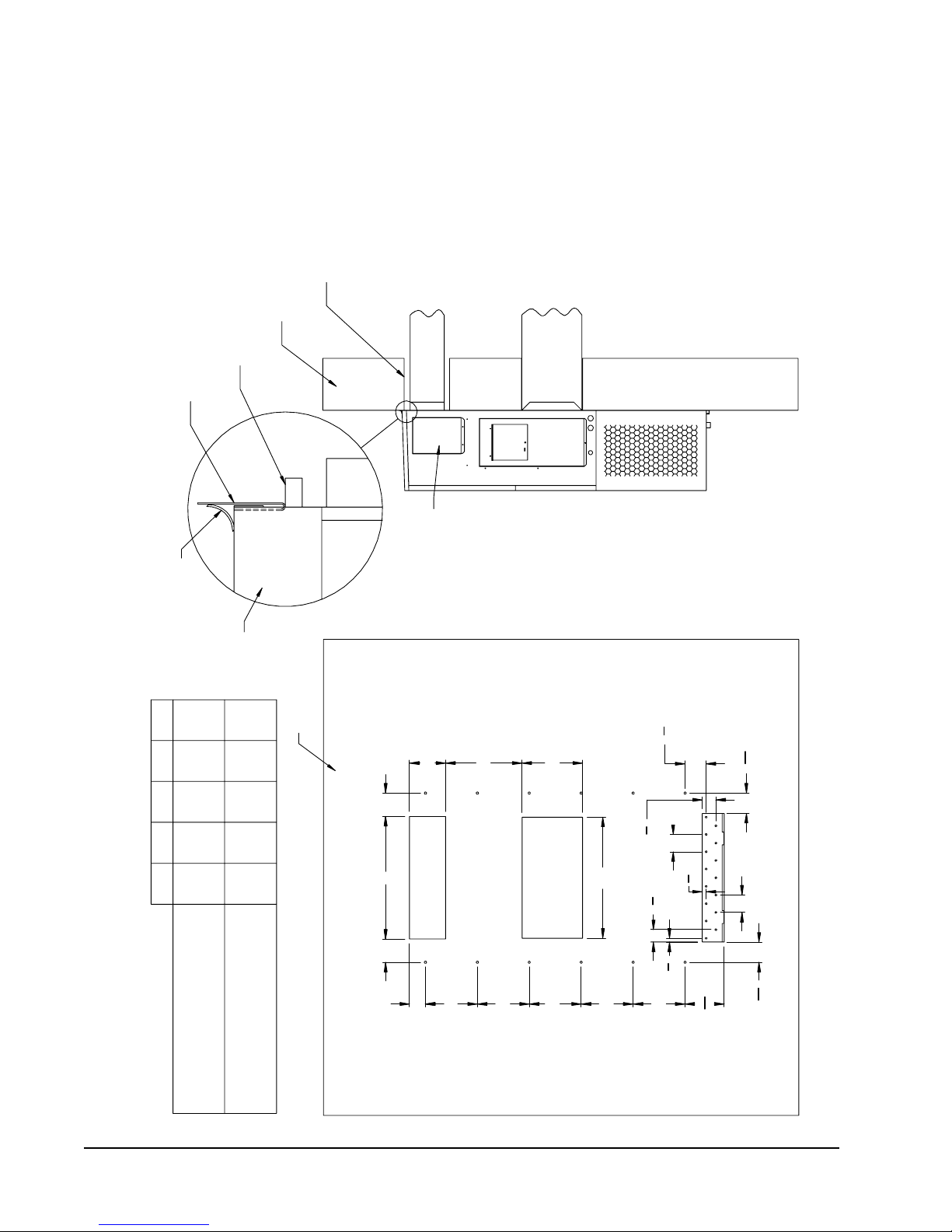
Figure 1.3A D25A, D25L, D35A, D35L
Mounting Instructions ...........................10
Figure 1.3B D28A, D28L, D36A, D36L, D42A, D42L,
Mounting Instructions ...........................11
Figure 1.3C D48A, D48L, D60A, D60L
Mounting Instructions ...........................12
Figure 1.4 Electric Heat Clearance .........................13
Figure 1.5 Wall Mounting Instructions ....................13
Figure 1.6 Wall Mounting Instructions ....................14
Figure 1.7 Common Wall Mounting Installations ......14
Figure 1.8 Circuit Routing Label ............................15
Figure 1.9 WIRING: VAC and VDC Supply Wiring
Landing Points .....................................17
Figure 1.10 Adjusting the 230/208VAC Transformer ..17
Figure 1.11 Bard Polarity-Voltage Monitor .................18
Figure 2.1 Refrigerant Sight Glass .........................23
Figure 2.2 Wall-Mount Unit Control Board ..............25
Figure 2.3 TEC-EYE
Figure 2.4 TEC-EYE
Figure 2.5 TEC-EYE
Figure 2.6 Fan Blade Setting .................................32
Figure 2.7 Dirty Filter Switch .................................32
Figure 2.8 Power Loss Relay Circuit .......................33
Figure 2.9 High Pressure Relay Circuit ...................33
Figure 2.10 Blower Motor Start Relay Circuit ............33
Figure 2.11 D25A/L, D35A/L Unit Control Panel .......34
Figure 2.12 D28A/L, D36A/L, D42A/L, D48A/L,
D60A/L Unit Control Panel ....................35
Figure 2.13 WIRING: D25A/L, D35A/L
Unit Wiring Diagram .............................36
Figure 2.14 WIRING: D28A/L, D36A/L, D42A/L, ..........
D48A/L, D60A/L Unit Wiring Diagram ....37
Figure 2.15 Troubleshooting Motor Power Supply ......39
Figure 2.16 Troubleshooting Motor Start Command ...40
Figure 2.17 Troubleshooting Speed Voltage ...............40
Figure 2.18 VDC Polarity Check ...............................41
Figure 2.19 Verifying Incoming Voltage: VDC .............42
TM
........................................................................................................................................27
Table 1.1 Electrical Specifications ..........................16
Table 2.1 Nominal Pressures ..................................23
Table 2.2 Blower Speed Voltage Chart .....................24
Table 2.3 Temp vs. Resistance of Temp Sensor. ........31
Table 2.4 Indoor Blower Performance ......................32
Table 2.5 Troubleshooting 48VDC Blower Motor ........39
Table 2.6 Blower Speed Voltage Chart .....................40
TM
Display ................................27
TM
Connection to Unit Control ....27
TM
Status Display......................28
Manual 2100-643C
Page 2 of 59
Page 3

GENERAL INFORMATION
DC FREE COOLING UNIT SYSTEM
The Bard DC Free Cooling Unit system is composed
of two (2) D-Series DUAL-TEC™ wall-mount air
conditioners matched with one (1) LC Series lead/lag
controller. The D-Series, specifically engineered for the
telecom market, can provide outdoor air cooling during
power loss situations through the use of onsite -48VDC
positive ground battery banks.
NOTE: The LC Series lead/lag controller and the
D-Series wall-mount units are designed
specifically to work together. The controller
cannot run other Bard models or other brands
of systems, nor can other controllers or
thermostats run the D-Series wall-mount units.
They are a complete system, and must be used
together.
WALL-MOUNT AIR CONDITIONER
UNITS
The D-Series units operate on both VAC and VDC power
under normal power supply conditions. If there is loss
of VAC power supply (shore and/or back-up generator)
the unit will continue to operate as free cooling or
ventilation system using the shelter’s VDC power. The
indoor blower and free cooling unit operate from -48VDC
and no inverter is required.
The units will supply 100% of rated cooling airflow
in free cooling mode with ability to exhaust the same
amount through the unit itself without any additional
relief openings in the shelter.
Each of these units are fully charged with refrigerant
and have auxilliary heat installed.
GENERAL
The equipment covered in this manual is to be installed
by trained, experienced service and installation
technicians.
The refrigerant system is completely assembled and
charged. All internal wiring is complete.
The unit is designed for use with or without duct work.
Flanges are provided for attaching the supply and return
ducts.
These instructions explain the recommended method
to install the air cooled self-contained unit and the
electrical wiring connections to the unit.
These instructions and any instructions packaged with
any separate equipment required to make up the entire
air conditioning system should be carefully read before
beginning the installation. Note particularly any tags
and/or labels attached to the equipment.
While these instructions are intended as a general
recommended guide, they do not supersede any national
and/or local codes in any way. Authorities having
jurisdiction should be consulted before the installation
is made. See ADDITIONAL PUBLICATIONS for
information on codes and standards.
Sizing of systems for proposed installation should
be based on heat loss calculation made according to
methods of Air Conditioning Contractors of America
(ACCA). The air duct should be installed in accordance
with the Standards of the National Fire Protection
Association for the Installation of Air Conditioning and
Ventilating Systems of Other Than Residence Type,
NFPA No. 90A, and Residence Type Warm Air Heating
and Air Conditioning Systems, NFPA No. 90B. Where
local regulations are at a variance with instructions,
installer should adhere to local codes.
SHIPPING DAMAGE
Upon receipt of equipment, the cartons should be
checked for external signs of shipping damage. If
damage is found, the receiving party must contact
the last carrier immediately, preferably in writing,
requesting inspection by the carrier’s agent.
These units must remain in upright position at all
times.
ADDITIONAL PUBLICATIONS
These publications can help when installing the air
conditioning system. They can usually be found at the
local library or purchased directly from the publisher.
Be sure to consult the current edition of each standard.
National Electrical Code ...................... ANSI/NFPA 70
Standard for the Installation of Air Conditioning
and Ventilating Systems ...................ANSI/NFPA 90A
Standard for Warm Air Heating
and Air Conditioning Systems ............ANSI/NFPA 90B
Load Calculation for Residential Winter
and Summer Air Conditioning ............. ACCA Manual J
Duct Design for Residential Winter and Summer
Air Conditioning and Equipment Selection
....................................................... ACCA Manual D
For more information, contact these publishers:
Air Conditioning Contractors of America (ACCA)
1712 New Hampshire Ave. N.W.
Washington, DC 20009
Telephone: (202) 483-9370 Fax: (202) 234-4721
American National Standards Institute (ANSI)
11 West Street, 13th Floor
New York, NY 10036
Telephone: (212) 642-4900 Fax: (212) 302-1286
Manual 2100-643C
Page 3 of 59
Page 4
American Society of Heating, Refrigeration and Air
Conditioning Engineers, Inc. (ASHRAE)
1791 Tullie Circle, N.E.
Atlanta, GA 30329-2305
Telephone: (404) 636-8400 Fax: (404) 321-5478
National Fire Protection Association (NFPA)
Batterymarch Park
P. O. Box 9101
Quincy, MA 02269-9901
Telephone: (800) 344-3555 Fax: (617) 984-7057
ANSI Z535.5 Definitions:
Danger: Indicate[s] a hazardous situation which, if
not avoided, will result in death or serious injury. The
signal word “DANGER” is to be limited to the most
extreme situations. DANGER [signs] should not be used
for property damage hazards unless personal injury risk
appropriate to these levels is also involved.
Warning: Indicate[s] a hazardous situation which, if
not avoided, could result in death or serious injury.
WARNING [signs] should not be used for property
damage hazards unless personal injury risk appropriate
to this level is also involved.
Caution: Indicate[s] a hazardous situation which, if
not avoided, could result in minor or moderate injury.
CAUTION [signs] without a safety alert symbol may be
used to alert against unsafe practices that can result in
property damage only.
Notice: [this header is] preferred to address practices
not related to personal injury. The safety alert symbol
shall not be used with this signal word. As an
alternative to “NOTICE” the word “CAUTION” without
the safety alert symbol may be used to indicate a
message not related to personal injury.
!
WARNING
Electrical shock hazard.
Have a properly trained individual perform
these tasks.
Failure to do so could result in electric shock
or death.
!
WARNING
Fire hazard.
Maintain minimum 1/4” clearance between the
supply air duct and combustible materials in
the rst 3’ feet of ducting.
Failure to do so could result in re causing
damage, injury or death.
!
WARNING
Heavy item hazard.
Use more than one person to handle unit.
Failure to do so could result in unit damage or
serious injury.
Manual 2100-643C
Page 4 of 59
!
CAUTION
Cut hazard.
Wear gloves to avoid contact with sharp
edges.
Failure to do so could result in personal injury.
Page 5

SECTION 1:
INSTALLATION
INSTRUCTIONS
Manual 2100-643C
Page 5 of 59
Page 6
LIST OF NECESSARY MATERIALS/TOOLS
Additional hardware and miscellaneous supplies are needed for installation. These items are field supplied and must
be sourced before installation. This list also includes tools needed for installation.
LIST OF MATERIALS/TOOLS
• Personal protective equipment/safety devices
• Supply/return grilles
• Field-fabricated sleeves (if necessary)
• Fasteners sufficient for mounting the units such as
5/16" diameter anchor/carriage/lag bolts
• 7/8" diameter washers
• Caulking materials
• Miscellaneous hand and power tools and jobsite or
shop materials
• Lifting equipment with the necessary capacity and
rigging to safely move/install the systems
• Electrical supplies:
- Two (2) 20A circuit breakers for the shelter DC
power plant (one per wall-mount unit)
- Two (2) various size circuit breakers for
the shelter AC breaker box (see Table 1.1:
Electrical Specifications on page 16)
- High-voltage wire of various gauges (see Table
1.1)
- Communication wire: 2-wire, 18 gauge,
shielded with drain
- Miscellaneous electrical supplies including
rigid/flexible conduit and fittings, junction
boxes, wire connectors and supports
The following are required and must be sourced
prior to installation of these units.
• Two (2) 20A circuit breakers for the shelter DC
power plant (one per wall-mount unit)
Circuit breakers for Emerson Network Power (ENP)
power plants (used in most telecomm shelters built
today) are available directly through the following
distributors:
• Emerson Network Power: 440.288.1122
• Master Electronics: 888.473.5297 or
www.onlinecomponents.com
Emerson Network Power (ENP) Part Number
• 20A circuit breaker: P/N 101601
Always confirm the application before ordering.
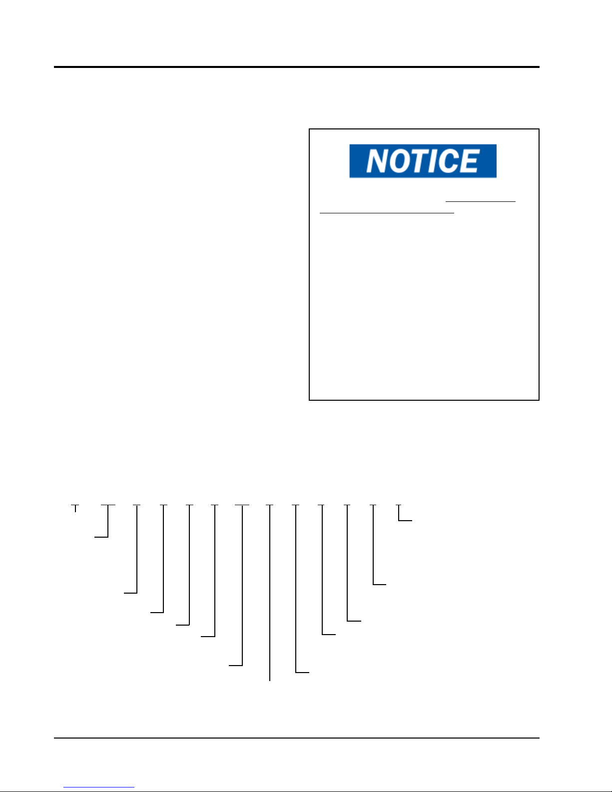
FIGURE 1.1
D-Series DUAL-TEC™ Wall-Mount Unit Model Nomenclature
D 25 A 2 P A 05 4 P X X X J
MODEL
SERIES
CAPACITY
25 – 2 Ton
28 – 2½ Ton
35 – 3 Ton
36 – 3 Ton
Manual 2100-643C
Page 6 of 59
42 – 3½ Ton
48 – 4 Ton
60 – 5 Ton
A – Right Hand
L – Left Hand
REVISION
PLC
VOLTS & PHASE
A – 230/208-60-1
B – 230/208-60-3
KW
0Z – 0 KW
05 – 5 KW
06 – 6 KW
-48VDC
Free Cooling
Unit
COIL OPTIONS
X – Standard
3 – Phenolic Coated Evaporator and
Condenser
SPECIAL FEATURES
COLOR OPTIONS
X – Beige
1 – White
4 – Buckeye Gray
FILTER OPTIONS
P – 2-Inch Pleated (MERV 8)
M – 2-Inch Pleated (MERV 11)
CONTROL MODULES
J – High Pressure Switch, Low Pressure
Switch, Compressor Control Module,
Low Ambient Control, Alarm Contacts,
Start Assist
C – J Module + Compressor Crankcase
Heater
Page 7
SITE PREPARATION
NEW SHELTER INSTALLATION VS.
RETROFIT INSTALLATION
These installation instructions cover both new shelter
installations and retrofit installations. Each installation
is unique and may require special accomodations and
modifications. Although Bard Manufacturing follows a
long-established tradition of manufacturing equipment
using industry standard dimensions for building
penetration, it is occasionally necessary to move or
enlarge supply and return openings when replacing
non-standardized equipment in a retrofit application.
MINIMUM CLEARANCE
D-Series wall-mount air conditioners are available in
both right-hand access models and left-hand access
models. Right-hand access models have the heat strip
access panel, external circuit breakers access panel
and internal controls access panel on the right side of
the unit. Left-hand access models are a mirror image
of the right-hand access models, and allow two wallmount units to be placed in relatively close proximity
and yet still allow complete access for maintenance
and repair.
On side-by-side installations, maintain a minimum of
26" clearance on control side to allow access to control
panel and heat strips, and to allow proper airflow to the
outdoor coil. For installations where units are installed
with both control panels facing each other (inward),
maintain a minimum of 36" clearance to allow access.
Additional clearance may be required to meet local or
national codes.
Care should be taken to ensure that the recirculation
and obstruction of condenser discharge air does not
occur. Recirculation of condenser discharge air can
be from either a single unit or multiple units. Any
object such as shrubbery, a building or a large object
can cause obstructions to the condenser discharge air.
Recirculation or reduced airflow caused by obstructions
will result in reduced capacity, possible unit pressure
safety lockouts and reduced unit service life.
For units with blow through condensers, such as the
D-Series units, it is recommended there be a minimum
distance of 10' between the front of the unit and
any barrier or 20' between the fronts of two opposing
(facing) units.
CLEARANCE TO COMBUSTIBLES
!
WARNING
Fire hazard.
Maintain minimum 1/4" clearance between the
supply air duct and combustible materials in
the rst 3' of ducting.
Failure to do so could result in re causing
damage, injury or death.
The unit itself is suitable for 0" clearance, but the
supply air duct flange and the first 3' of supply air duct
require a minimum of 1/4" clearance to combustible
material. However, it is generally recommended that
a 1" clearance is used for ease of installation and
maintaining the required clearance to combustible
material. See Figures 1.3A-C on pages 10-12 for
details on opening sizes.
Minimum Clearances Required to
Combustible Materials
MODELS
All covered by this
manual
SUPPLY AIR DUCT
FIRST 3'
1/4" 0"
CABINET
MODEL IDENTIFICATION
Identify the specific model using the model
nomenclature information found in Figure 1.1 and/
or model/serial tag found on the unit on the opposite
side of the control and access panels. See Figure 1.2
on page 8 for dimensions and critical installation
requirements.
Clearances Required for Service Access
and Adequate Condenser Airflow
MODELS LEFT SIDE RIGHT SIDE
All covered by this manual 26" 26"
Units with control panels
facing each other (inward)
36" between units
Manual 2100-643C
Page 7 of 59
Page 8

FIGURE 1.2
Dimensions of Basic Unit for Architectural and Installation Requirements (Nominal)
Width
Depth
Model
D25A/L
D35A/L
D28A/L
D36A/L
D42A/L
D48A/L
D60A/L
(W)
38.200 17.125 74.563 7.88 27.88 13.88 27.88 40.00 10.88 29.75 17.93 30.75 32.75 33.25 31.00 2.75 39.13 26.75 9.14 4.19 12.00 9.00
42.075 22.432 84.875 9.88 29.88 15.88 29.88 43.88 13.56 31.66 30.00 32.68 26.94 34.69 32.43 3.37 43.00 23.88 10.00 1.44 16.00 1.88
42.075 22.432 93.000 9.88 29.88 15.88 29.88 43.88 13.56 37.00 30.00 40.81 35.06 42.81 40.56 3.37 43.00 31.00 10.00 1.44 16.00 10.00
Height
(D)
Supply Return
(H)
A B C B E F G I J K L M N O P Q R S T
All dimensions are in inches. Dimensional drawings are not to scale.
Side View
Built In
Rain Hood
4° Pitch
D
1.250
Cond.
Air
Inlet
D
1.250
2.13
J
Drain
Electric
Heat
A
I
C H
K
Heater
Access
Panel
C. Breaker/
Disconnect
Access Panel
(Lockable)
Econ. Hood
Side Wall
Mounting
Brackets
(Built In)
Top Rain
Flashing
Shipping
Location
Optional
Electrical
Entrances
L
M
N
E
O
Supply Air Opening
B
Return Air Opening
P
Back View
Q
W
D**A
RIGHT
HAND
UNIT
D**L
LEFT
HAND
UNIT
Built In
Rain Hood
W
ECON Hood
F
Ventilation Air
Cond.
G
Air
Outlet
4° Pitch
Heater
Access
Panel
Electric
Heat
C. Breaker/
Disconnect
Access Panel
(Lockable)
7.000
Low Voltage
Electrical
Entrance
High Voltage
Electrical
Entrance
Front View
E
.44
R
S
S
O
Supply Air Opening
B
Side Wall
Mounting
Brackets
(Built In)
Top Rain
Flashing
Shipping
Location
2.13
A
I
.44
Bottom Installation
Bracket
MIS-3849
R
S
S
S
S
S
T
S
S
S
T
Drain
Return Air Opening
Bottom
Installation
Bracket
Back View
Manual 2100-643C
Page 8 of 59
Optional
Electrical
Entrances
M
P
N
Q
C
Ventilation Air
H
K
L
Cond.
J
Air
Inlet
7.000
Low Voltage
Electrical
Entrance
High Voltage
Electrical
Entrance
Condenser
Air Outlet
Front ViewSide View
F
G
MIS-3848
Page 9
WALL-MOUNT UNIT INSTALLATION
MOUNTING THE UNITS
!
WARNING
Heavy item hazard.
Use more than one person to handle unit.
Failure to do so could result in unit damage or
serious injury.
NOTE: It may be best to spot some electrical knockouts
(such as those located on the back of the wallmount unit) before units are mounted and access is
unavailable or limited (see Figure 1.2 to locate prepunched knockouts).
Two holes for the supply and return air openings must
be cut through the wall as shown in Figures 1.3AC on pages 10-12. On wood frame walls, the wall
construction must be strong and rigid enough to carry
the weight of the unit without transmitting any unit
vibration. Concrete block walls must be thoroughly
inspected to insure that they are capable of carrying
the weight of the installed unit.
In retrofit (unit replacement) installations, the openings
cut for the original equipment may not line up exactly
with needs of this installation. Modifications may need
to be made, such as increasing or decreasing the size
of the wall cutouts. The existing bolt placement may
not line up in which case the original bolts would need
to be removed or cut away.
1. These units are secured by wall mounting flanges
which secure the unit to the outside wall surface at
both sides. A bottom mounting bracket, attached
to skid for shipping, is provided for ease of
installation, but is not required.
2. The unit itself is suitable for 0" clearance, but the
supply air duct flange and the first 3' of supply
air duct require a minimum of 1/4" clearance to
combustible material. However, it is generally
recommended that a 1" clearance is used for
ease of installation and maintaining the required
clearance to combustible material. See Figures
1.3A-C for details on opening sizes.
3. Locate and mark lag bolt locations and location for
optional bottom mounting bracket, if desired (see
Figures 1.3A-C).
4. Mount bottom mounting bracket (if used).
5. If desired, hook top rain flashing (attached to frontright of supply flange for shipping) under back
bend of top.
6. Position unit in opening and secure with fasteners
sufficient for the application such as 5/16" lag/
anchor/carriage bolts; use 7/8" diameter flat washers
on the bolts. It is recommended that a bead of
silicone caulking be placed behind the side
mounting flanges.
7. Secure optional rain flashing to wall and caulk
across entire length of top (see Figures 1.3A-C).
8. For additional mounting rigidity, the return air
and supply air frames or collars can be drilled
and screwed or welded to the structural wall itself
(depending upon wall construction). Be sure to
observe required clearance if combustible wall.
9. A plastic drain hose extends from the drain pan at
the top of the unit down to the unit base. There are
openings in the unit base for the drain hose to pass
through. In the event the drain hose is connected
to a drain system of some type, it must be an open
or vented type system to assure proper drainage.
Manual 2100-643C
Page 9 of 59
Page 10
FOUR SIDES OF SUPPLY
Wall Opening and Hole Location View
1/4" MIN. CLEARANCE FROM
COMBUSTIBLE MATERIALSCRECOMMENDED 1" CLEARANCE FROM
REQUIRED DIMENSIONS TO MAINTAIN
COMBUSTIBLE MATERIALS
REQUIRED DIMENSIONS TO MAINTAIN
AIR DUCT IS REQUIRED
1/4" CLEARANCE ON ALL
FROM COMBUSTABLE
MIS-3820
MATERIALS
FOAM AIR SEAL
SUPPLIED
RAIN FLASHING
SEAL WITH BEAD
FIGURE 1.3A
OF CAULKING ALONG
Mounting Instructions
ENTIRE LENGTH OF TOP.
D25A, D25L, D35A, D35L
ED
17 5/8
3 11/16
TOP
4 7/16
WALL STRUCTURE
WALL
SUPPLY AIR
DUCT
PANEL
HEATER ACCESS
B
TOP FLASHING AT TIME OF INSTALLATION.
IT IS RECOMMENDED THAT A BEAD OF
THE SIDE MOUNTING FLANGES AND UNDER
RETURN AIR
OPENING
NOTES:
SILICONE CAULKING BE PLACED BEHIND
W**A UNIT SHOWN, W**L UNIT
CONTROLS AND HEATER ACCESS
IS ON OPPOSITE (LEFT) SIDE.
Right Side View
"
7
8
4
E
14"
"
16
11
4
5 3/8
B
8 3/8A9 7/829 7/8
4 5/8 16 7/8
28 3/8
Manual 2100-643C
Page 10 of 59
C
A
Supply Opening
Return Opening
28"
C
D
12"
12"
12"
12"
4"
"
Typ.
1
8
3
"
7
8
"
7
8
2
"
7
8
12"
4"
Typ.
"
1
16
9
"
16
11
4
Page 11
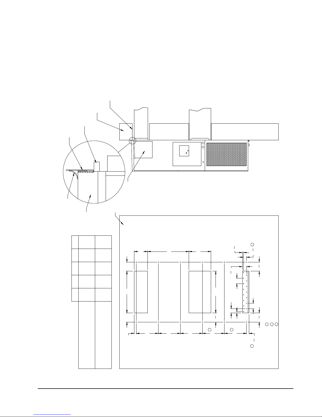
D
16"
16"
16"
16"
16"
1
7
8
"
6
1
2
" 6
1
2
"
2
1
8
"
7
8
"
1"
3"
4"
Typ.
4"
Typ.
6
1
2
"
30"
E
16"
A CC
3
1
8
"
B
Wall Opening and Hole Location View
RETURN AIR
1
REQUIRED DIMENSIONS TO MAINTAIN
1/4" MIN. CLEARANCE FROM
COMBUSTIBLE MATERIALS
REQUIRED DIMENSIONS TO MAINTAIN
29
DUCT
COMBUSTIBLE MATERIALS
A B C DE
30 1/2
10 1/2
6 1/4 1 1/4 29 3/4
32 12 5 1/2
2
NOTES:
WALL STRUCTURE
1
SUPPLY AIR
IT IS RECOMMENDED THAT A BEAD OF
OPENING
Right Side View
RAIN FLASHING
SILICONE CAULKING BE PLACED BEHIND
RECOMMENDED 1" CLEARANCE FROM
THE SIDE MOUNTING FLANGES AND UNDER
TOP FLASHING AT TIME OF INSTALLATION.
TOP.
PANEL
HEATER ACCESS
FOUR SIDES OF SUPPLY
AIR DUCT IS REQUIRED
FROM COMBUSTABLE
WALL
1/4" CLEARANCE ON ALL
MATERIALS
Supply Opening
FOAM AIR SEAL
SUPPLIED
SEAL WITH BEAD
OF CAULKING ALONG
ENTIRE LENGTH OF
TOP
1
Return Opening
MIS-416 E
Dimension is 21" on 95" tall units.
2
Dimension is 10" on T48H1 & T60H1.
2
Dimension is 6" on T48H1 & T60H1.
3
3
FIGURE 1.3B
Mounting Instructions
D28A, D28L, D36A, D36L, D42A, D42L
Manual 2100-643C
Page 11 of 59
Page 12
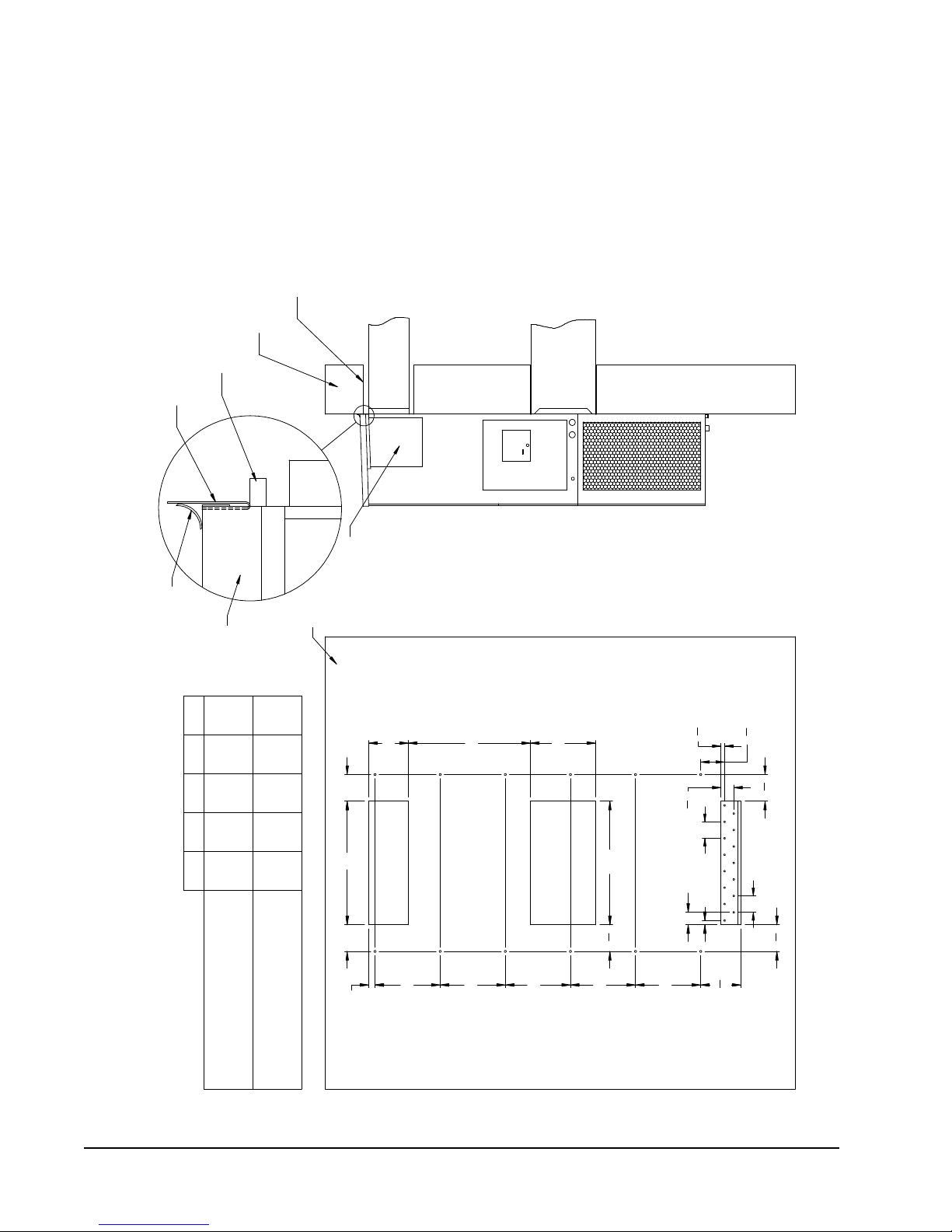
D
16"
16"
16"
16"
16"
2
"6
8
" 5
8 97
"
1"
3"
Typ.
1
4"
4"
Typ.
6
1
2
"
30"
E
16"
A CC
"
7
8
3
B
"
8
7
1
1
2
"6
1 1/430 1/2
1/4" CLEARANCE ON ALL
SUPPLIED
FOAM AIR SEAL
A
Supply Opening
SILICONE CAULKING BE PLACED BEHIND
DUCT
FOUR SIDES OF SUPPLY
FROM COMBUSTABLE
1/4" MIN. CLEARANCE FROM
COMBUSTIBLE MATERIALS
REQUIRED DIMENSIONS TO MAINTAIN
OPENING
COMBUSTIBLE MATERIALS
B D E
PANEL
AIR DUCT IS REQUIRED
32
10 1/2
Right Side View
SUPPLY AIR
RECOMMENDED 1" CLEARANCE FROM
MIS-3789
RAIN FLASHING
REQUIRED DIMENSIONS TO MAINTAIN
12
TOP.
MATERIALS
5 1/2
WALL STRUCTURE
2
6 1/4
29
29 3/4
IT IS RECOMMENDED THAT A BEAD OF
THE SIDE MOUNTING FLANGES AND UNDER
WALL
C
Wall Opening and Hole Location View
NOTES:
TOP FLASHING AT TIME OF INSTALLATION.
HEATER ACCESS
RETURN AIR
SEAL WITH BEAD
OF CAULKING ALONG
ENTIRE LENGTH OF
TOP
Return Opening
FIGURE 1.3C
Mounting Instructions
D48A, D48L, D60A, D60L
Manual 2100-643C
Page 12 of 59
Page 13
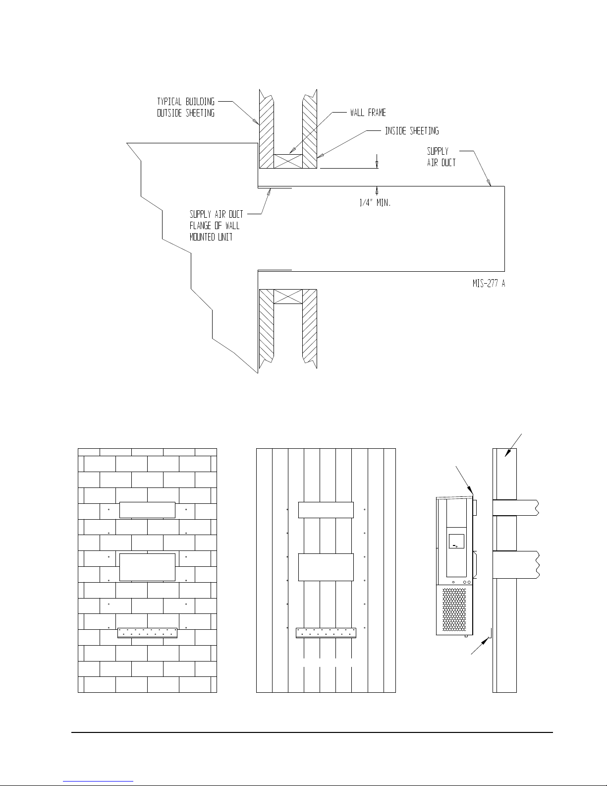
FIGURE 1.4
DUCT
OPENING
RETURN AIR
SUPPLY AIR
WOOD FRAME WALL INSTALLATION
OPENING
WALL BEFORE
MOUNT ON UNIT
OPENING
BEFORE INSTALLATION
BOTTOM MOUNTING
CONCRETE BLOCK WALL INSTALLATION
BRACKET. MOUNT ON
OPENING
WOOD OR STEEL SIDING
OPENING
INSTALLING UNIT.
RETURN AIR
WALL STRUCTURE
RETURN AIR
SUPPLY AIR
FACTORY SUPPLIED
RAIN FLASHING.
SUPPLY AIR
MIS-548 A
SIDE VIEW
Electric Heat Clearance
Wall Mounting Instructions
See FIGURE 2 – Mounting Instructions
FIGURE 1.5
Manual 2100-643C
Page 13 of 59
Page 14

FIGURE 1.6
I
A
C
K
E + 1.000
B
1.000
SUPPLY DUCT
OVER FRAME
INTERIOR FINISHED WALL
ALL AROUND DUCT
FRAMING MATERIAL
EXTERIOR FINISH WALL
OPENING
FOR ACTUAL DIMENSIONS.
2 x 4'S, 2 x 6'S &/OR
STRUCTURAL STEEL
ATTACH TO TOP
1.000" CLEARANCE
1.000" CLEARANCE
PLATE OF WALL
C
SEE UNIT DIMENSIONS, FIGURE 2,
OPENING
RETURN DUCT
2 x 6
ATTACH TO BOTTOM
OVER FRAME
PLATE OF WALL
L
THIS STRUCTURAL MEMBER
LOCATED TO MATCH STUD
SPACING FOR REST OF WALL.
A SECOND MEMBER MAY BE
REQUIRED FOR SOME WALLS.
MIS-549 B
ALL AROUND DUCT
SUPPLY DUCT MAY BE LOCATED IN AN ATTIC
OPENING W/ GRILLE
SUPPLY AIR DUCT
RAFTERS
RAFTERS
RETURN AIR
OPENING W/ GRILLE
DUCTED SUPPLY
OR BELOW CEILING RAFTERS AS SHOWN
FINISHED CEILING SURFACE
RAIN
FLASHING
RAIN
FLASHING
RETURN AT UNITNO DUCT
RETURN AIR
FINISHED CEILING SURFACE
FREE AIR FLOW
OUTSIDE
WALL
OUTSIDE
WALL
SUPPLY AIR DUCT
W/ GRILLE
Wall Mounting Instructions
SEE UNIT DIMENSIONS, FIGURE 1-2,
FOR ACTUAL DIMENSIONS
FIGURE 1.7
Common Wall Mounting Installations
Manual 2100-643C
Page 14 of 59
Page 15
WALL-MOUNT UNIT SUPPLY WIRING
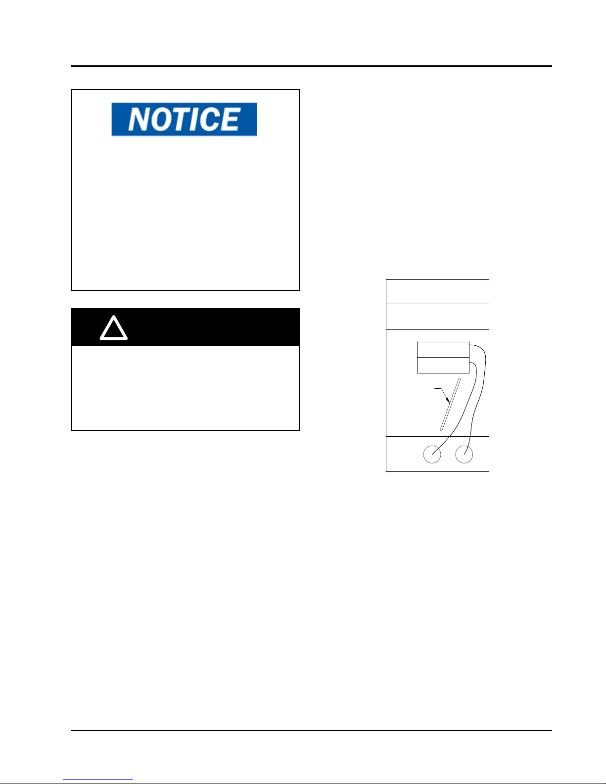
NOTICE / AVIS
ROUTE ALL HIGH VOLTAGE FIELD
WIRES TO THE RIGHT OF THE WIRE
SHIELD AS SHOWN
ACHEMINER LES FILS HAUTE
TENSION SUR LA DROITE VERS LA
PROTECTION, COMME INDIQUÉ
VAC CIRCUIT BREAKER
/DISJONCTEUR
WIRE SHIELD /
PROTECTION
WHITE 3/16" LETTERING
7961-807
VDC CIRCUIT BREAKER
/DISJONCTEUR
All models covered by this installation
instruction require dual power sources:
VAC utility power to run the compressor, heat
and outdoor fan motor and -48 VDC power
to operate the indoor blower and DC free
cooling damper.
These units require a positive ground
-48 VDC copper conductor field wire
connection. Refer to the unit wiring diagram
for more information.
!
WARNING
Route all field wires to the right of the wire shield as
shown in the circuit routing label found in Figure 1.8
(and also on the wall-mount units).
Run communication wires in separate conduit
whenever possible. If a unique installation occurs
where it is not possible to isolate the communication
wires, it is permissible to run communication wires
in a conduit which contains a dedicated VDC voltage
line. In all cases, the communication wires must be
shielded, twisted wire and utilize proper filtration at the
main communications board. It is never permissible to
run communication wires with VAC voltage lines.
FIGURE 1.8
Circuit Routing Label
Electrical shock hazard.
Have a properly trained individual perform
these tasks.
Failure to do so could result in electric shock
or death.
Refer to the unit rating plate or Table 1.1 on page
16 for wire sizing information and maximum fuse or
circuit breaker size. Each outdoor unit is marked with
a “Minimum Circuit Ampacity”. The field wiring used
must be sized to carry
models are suitable only for connection with copper
wire. Each unit and/or wiring diagram will be marked
“Use Copper Conductors Only”. These instructions
must be adhered to. Refer to the National Electrical
Code (NEC) for complete current carrying capacity data
on the various insulation grades of wiring material. All
wiring must conform to NEC and all local codes.
The electrical data lists fuse and wire sizes (75°C
copper) for all models including the most commonly
used heater sizes. Also shown are the number of field
power circuits required for the various models with
heaters.
The unit rating plate lists a “Maximum Time Delay
Relay Fuse” or circuit breaker that is to be used with
the equipment. The correct size must be used for
proper circuit protection and also to assure that there
will be no nuisance tripping due to the momentary high
starting current of the compressor motor.
that amount of current. All
See Figure 1.9 on page 17 to reference VAC and VDC
supply wiring landing points.
IMPORTANT: 230/208V 1 phase and 3 phase
equipment use dual primary voltage transformers. All
equipment leaves the factory wired on 240V tap. It is
very important that the correct voltage tap is used. For
208V operation, reconnect from 240V to 208V tap (see
Figure 1.10). The acceptable operating voltage range
for the 240 and 208V taps are: 240V Tap (253 – 216)
and 208 Tap (220 – 197).
The disconnect access door on this unit may be locked
to prevent unauthorized access to the disconnect. To
convert for the locking capability, bend the tab located
in the bottom left-hand corner of the disconnect
opening under the disconnect access panel straight
out. This tab will now line up with the slot in the door.
When shut, a padlock may be placed through the hole
in the tab preventing entry.
Manual 2100-643C
Page 15 of 59
Page 16
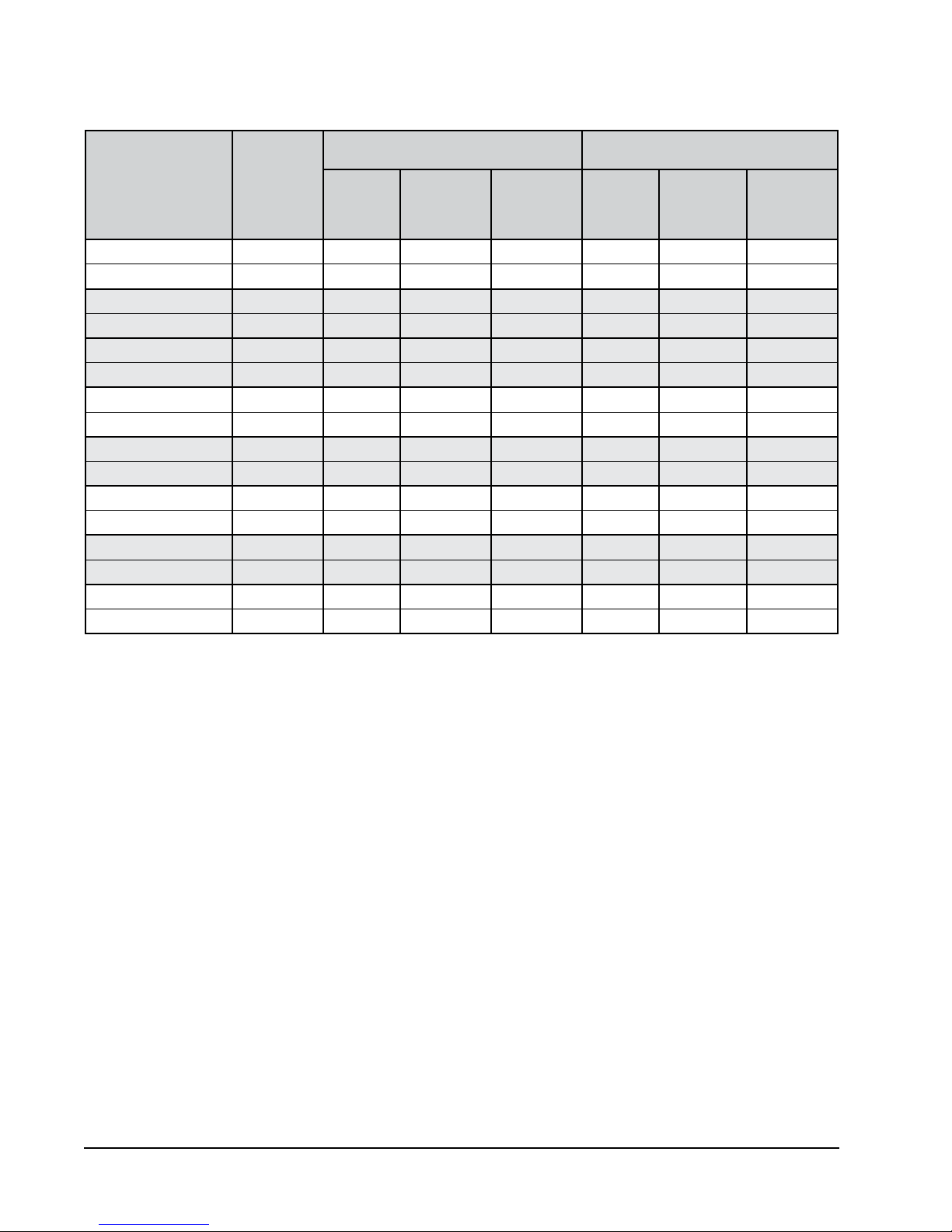
TABLE 1.1
Electrical Specifications
AC POWER CIRCUIT DC POSITIVE GROUND POWER CIRCUIT
Model
D25A2PA0Z/D25L2PA0Z 208/230-60-1 19 30 10/10 15.6 20 12
D25A2PA05/D25L2PA05 208/230-60-1 26 30 8/10 15.6 20 12
D35A2PA0Z/D35L2PA0Z 208/230-60-1 24 40 8/10 15.6 20 12
D35A2PA05/D35L2PA05 208/230-60-1 26 40 8/10 15.6 20 12
D35A2PB0Z/D35L2PB0Z 208/230-60-3 19 25 10/10 15.6 20 12
D35A2PB06/D35L2PB06 208/230-60-3 19 25 10/10 15.6 20 12
D28A2PA05/D28L2PA05 208/230-60-1 26 30 10/10 15.6 20 12
D28A2PB06/D28L2PB06 208/230-60-3 18 20 12/12 15.6 20 12
D36A2PA05/D36L2PA05 208/230-60-1 26 40 8/10 15.6 20 12
D36A2PB06/D36L2PB06 208/230-60-3 18 25 10/10 15.6 20 12
D42A2PA05/D42L2PA05 208/230-60-1 26 40 8/10 15.6 20 12
D42A2PB06/D42L2PB06 208/230-60-3 20 25 10/10 15.6 20 12
D48A2PA05/D48L2PA05 208/230-60-1 30 50 8/10 15.6 20 12
D48A2PB06/D48L2PB06 208/230-60-3 20 30 10/10 15.6 20 12
D60A2PA05/D60L2PA05 208/230-60-1 36 60 6/10 15.6 20 12
D60A2PB06/D60L2PB06 208/230-60-3 30 40 8/10 15.6 20 12
Rated Volts,
Hertz & Phase
Minimum
Circuit
Ampacity
Maximum
External Fuse or
Ckt. Breaker
Field Power/
Ground Wire
Size
Minimum
Circuit
Ampacity
Maximum
External Fuse
or Ckt. Breaker
Field Power/
Ground Wire
Size
These “Minimum Circuit Ampacity” values are to be used for sizing the field power conductors. Refer to the National Electric Code (latest
version), Article 310 for power conductor sizing.
CAUTION: When more than one field power circuit is run through one conduit, the conductors must be derated. Pay special attention
to note 8 of Table 310 regarding Ampacity Adjustment Factors when more than three current carrying conductors are in a
raceway.
Maximum size of the time delay fuse or circuit breaker for protection of field wiring conductors.
Based on 75°C copper wire. All wiring must conform to the National Electric Code and all local codes.
Manual 2100-643C
Page 16 of 59
Page 17
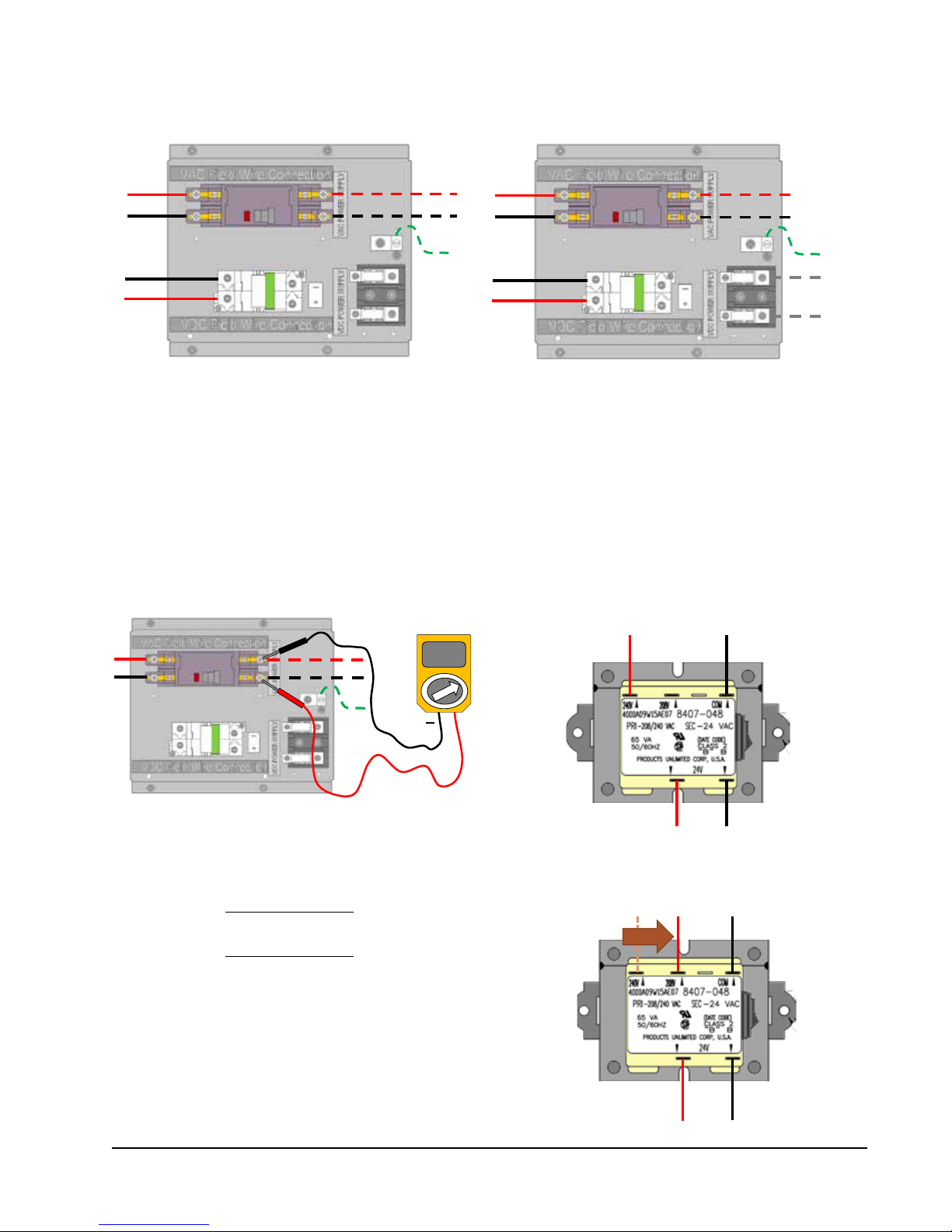
FIGURE 1.9
VAC and VDC Supply Wiring Landing Points
.
Field
Wiring
VDC
.
.
-
Factory
Wiring
VAC
Field Wiring
Factory
+
NOTE: Right-hand access model wiring landing points
are shown here; left-hand access models will
mirror this image.
Wiring
NOTE: Right-hand access model wiring landing points
are shown here; left-hand access models will
mirror this image.
FIGURE 1.10
Adjusting the 230/208 VAC Transformer
230/208V 1 phase and 3 phase equipment use dual primary voltage transformers. All equipment leaves the factory wired on
240V tap. It is very important that the correct voltage tap is used. For 208V operation, reconnect from 240V to 208V tap.
The acceptable operating voltage range for the 240 and 208V taps are: 240V Tap (253 – 216) and 208 Tap (220 – 197).
1. Verify incoming AC voltage: Multimeter set to VAC
2. If incoming AC voltage is 220VAC or above...
...do not adjust transformer
.
Shelter supply breaker in ON position
Bard system breaker in OFF position
230V/208V Single Phase Voltage Range:
197VAC – 253VAC
230V/208V Three Phase Voltage Range:
197VAC – 253VAC
(not shown)
230VAC
+
3. If incoming AC voltage is below 220VAC...
...shut off AC breaker to unit
and move factory "240V" wire to "208V" terminal
Manual 2100-643C
Page 17 of 59
Page 18
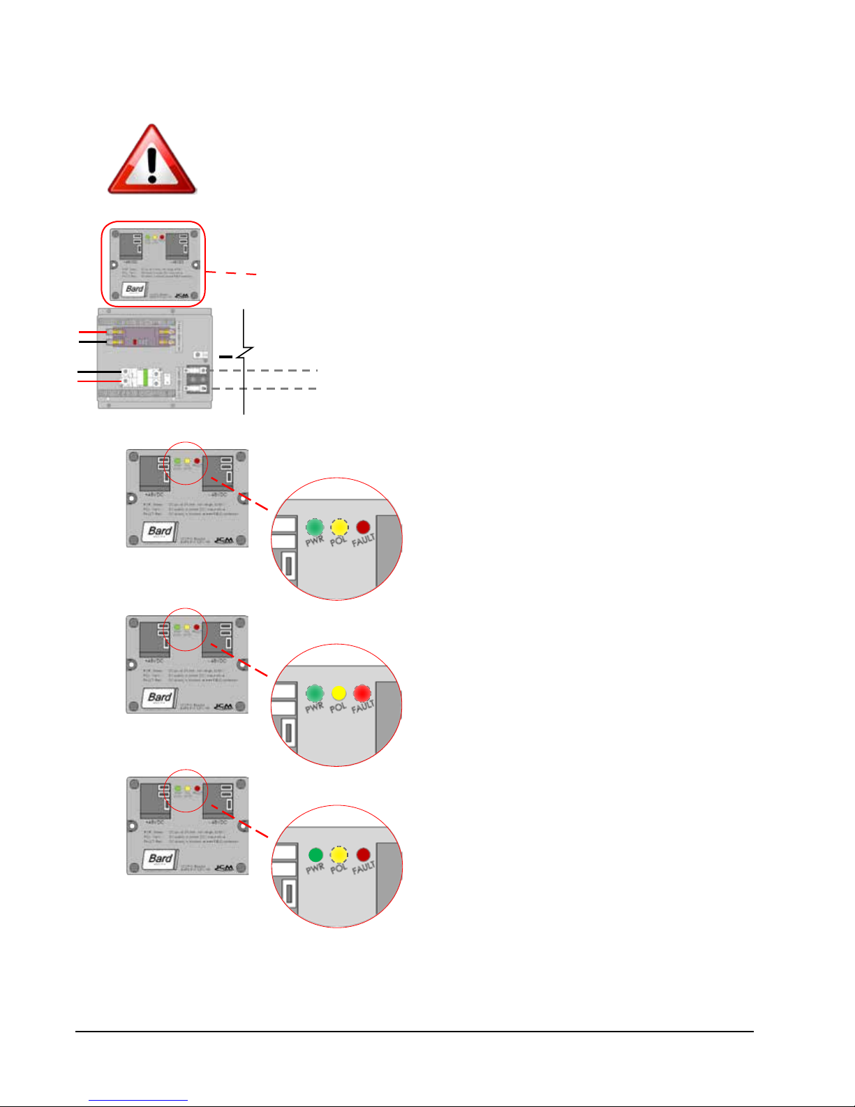
FIGURE 1.11
Bard Polarity-Voltage Monitor
If the VDC wiring is not terminated correctly on the specific polarity-indicated
terminals of the VDC terminal block, the VDC controls and motors will not activate
and the wall-mounted unit will not function.
The Bard Polarity-Voltage Monitor continually monitors for correct polarity and
voltage. If field wiring is connected improperly, or the voltage is outside of the
system parameters, the Polarity-Voltage Monitor will not allow any VDC voltage to
enter the system, protecting the internal controls and equipment.
+
When field wiring is correct in voltage and polarity, the
green power (PWR) LED and yellow polarity (POL) LED
will light, and system will operate normally.
If field wiring is incorrect in polarity, the red FAULT
LED will light, and the monitor will not allow VDC
voltage into the system.
If field wiring is correct in polarity but outside of the
required 40VDC – 56VDC, the green PWR LED will not
illuminate and the monitor not allow VDC voltage into
the system.
If the Polarity-Voltage Monitor is showing a problem with polarity and/or voltage, see pages 41 and 42 of the Service
section of this manual for instructions on checking VDC polarity and verifying incoming VDC voltage.
Manual 2100-643C
Page 18 of 59
Page 19

PRELIMINARY START-UP
RUNNING IN STAND ALONE (ORPHAN) MODE
With both AC and DC breakers turned on, each D-Series wall-mount system has the capability to run without the
controller attached—this feature is called Stand Alone or Orphan Mode, and it basically keeps the shelter between
60°F and 78°F by the use of the factory-installed return air sensor in each wall-mount unit.
During installation, this allows deactivation of one of the two existing, older wall-mount units, while keeping the
shelter cool with the other unit still operating. Once the first of the two Bard wall-mount units is installed, Orphan
Mode can be enabled early in the installation—keeping the climate inside the shelter stable and the installers
comfortable while the remainder of the older equipment is removed and the second Bard wall-mount unit and
controller are installed.
Additionally, should either or both D-Series wall-mount units lose communication with the controller (such as during
maintenance), they will continue to serve the shelter's needs until a repair can be made.
See the LC Series controller manual for information on connecting the communication wiring from the controller to
the two wall-mount units and operating the DC free cooling unit system.
Manual 2100-643C
Page 19 of 59
Page 20

Manual 2100-643C
Page 20 of 59
Page 21

SECTION 2:
SERVICE
INSTRUCTIONS
Manual 2100-643C
Page 21 of 59
Page 22

GENERAL REFRIGERANT INFORMATION
REMEMBER: When adding R-410A refrigerant, it must
come out of the charging cylinder/tank as a liquid to
avoid any fractionation and to insure optimal system
performance. Refer to instructions for the cylinder that
These units require R-410A refrigerant and
polyol ester oil.
GENERAL
1. Use separate service equipment to avoid cross
contamination of oil and refrigerants.
2. Use recovery equipment rated for R-410A
refrigerant.
3. Use manifold gauges rated for R-410A (800
psi/250 psi low).
R-410A is a binary blend of HFC-32 and HFC-125.
4.
5. R-410A is nearly azeotropic—similar to R-22 and
R-12. Although nearly azeotropic, charge with
liquid refrigerant.
6. R-410A operates at 40-70% higher pressure than
R-22, and systems designed for R-22 cannot
withstand this higher pressure.
7. R-410A has an ozone depletion potential of zero,
but must be reclaimed due to its global warming
potential.
8. R-410A compressors use polyol ester oil.
9. Polyol ester oil is hygroscopic; it will rapidly absorb
moisture and strongly hold this moisture in the oil.
10. A liquid line dryer must be used—even a deep
vacuum will not separate moisture from the oil.
11. Limit atmospheric exposure to 15 minutes.
12. If compressor removal is necessary, always plug
compressor immediately after removal. Purge with
small amount of nitrogen when inserting plugs.
TOPPING OFF SYSTEM CHARGE
If a leak has occurred in the system, Bard
Manufacturing recommends reclaiming, evacuating
(see criteria above) and charging to the nameplate
charge. If done correctly, topping off the system charge
can be done without problems.
With R-410A, there are no significant changes in the
refrigerant composition during multiple leaks and
recharges. R-410A refrigerant is close to being an
azeotropic blend (it behaves like a pure compound
or single component refrigerant). The remaining
refrigerant charge in the system may be used after
leaks have occurred. “Top-off” the charge by utilizing
the pressure charts on the inner control panel cover as
a guideline.
is being utilized for proper method of liquid extraction.
SAFETY PRACTICES
1. Never mix R-410A with other refrigerants.
2. Use gloves and safety glasses. Polyol ester oils can
be irritating to the skin, and liquid refrigerant will
freeze the skin.
3. Never use air and R-410A to leak check; the
mixture may become flammable.
4. Do not inhale R-410A—the vapor attacks
the nervous system, creating dizziness, loss
of coordination and slurred speech. Cardiac
irregularities, unconsciousness and ultimately
death can result from breathing this concentration.
5. Do not burn R-410A. This decomposition produces
hazardous vapors. Evacuate the area if exposed.
6. Use only cylinders rated DOT4BA/4BW 400.
7. Never fill cylinders over 80% of total capacity.
8. Store cylinders in a cool area, out of direct
sunlight.
9. Never heat cylinders above 125°F.
10. Never trap liquid R-410A in manifold sets, gauge
lines or cylinders. R-410A expands significantly at
warmer temperatures. Once a cylinder or line is full
of liquid, any further rise in temperature will cause
it to burst.
R410-A REFRIGERANT CHARGE
This unit was charged at the factory with the quantity
of refrigerant listed on the serial plate. AHRI capacity
and efficiency ratings were determined by testing with
this refrigerant charge quantity.
The pressure table found on the following page
shows nominal pressures for the units. Since many
installation specific situations can affect the pressure
readings, this information should only be used by
certified technicians as a guide for evaluating proper
system performance. They shall not be used to adjust
charge. If charge is in doubt, reclaim, evacuate and
recharge the unit to the serial plate charge.
PRESSURE SERVICE PORTS
High and low pressure service ports are installed on
all units so that the system operating pressures can be
observed. A pressure table covering all models can be
found on page 23. It is imperative to match the correct
pressure table to the unit by model number.
Manual 2100-643C
Page 22 of 59
Page 23

This unit employs high-flow Coremax valves instead of
the typical Shrader type valves.
WARNING! Do NOT use a Schrader valve core removal
tool with these valves. Use of such a tool could result
in eye injuries or refrigerant burns!
TABLE 2.1
Nominal Pressures
To change a Coremax valve without first removing the
refrigerant, a special tool is required which can be
obtained at www.fastestinc.com/en/SCCA07H. See the
replacement parts manual for replacement core part
numbers.
Model
D25A/L
D28A/L
D35A/L
D36A/L
D42A/L
D48A/L
D60A/L
Return Air
Temperature
75° DB
62° WB
80° DB
67° WB
85° DB
72° WB
75° DB
62° WB
80° DB
67° WB
85° DB
72° WB
75° DB
62° WB
80° DB
67° WB
85° DB
72° WB
75° DB
62° WB
80° DB
67° WB
85° DB
72° WB
75° DB
62° WB
80° DB
67° WB
85° DB
72° WB
75° DB
62° WB
80° DB
67° WB
85° DB
72° WB
75° DB
62° WB
80° DB
67° WB
85° DB
72° WB
Pressure
Low Side
High Side
Low Side
High Side
Low Side
High Side
Low Side
High Side
Low Side
High Side
Low Side
High Side
Low Side
High Side
Low Side
High Side
Low Side
High Side
Low Side
High Side
Low Side
High Side
Low Side
High Side
Low Side
High Side
Low Side
High Side
Low Side
High Side
Low Side
High Side
Low Side
High Side
Low Side
High Side
Low Side
High Side
Low Side
High Side
Low Side
High Side
Low Side Pressure ±4 PSIG
High Side Pressure ±10PSIG
Air Temperature Entering Outdoor Coil, Degree °F
75 80 85 90 95 100 105 110 115 120
132
133
134
136
137
138
140
142
144
292
141
299
146
309
137
279
146
286
151
296
118
327
126
335
130
347
133
313
142
321
147
332
131
315
140
323
145
334
133
325
142
333
147
345
129
353
138
362
143
375
308
142
316
147
327
137
299
146
307
151
318
120
349
128
358
132
371
135
327
144
335
149
347
132
331
141
339
146
351
136
341
145
350
150
362
130
362
139
371
144
384
327
143
335
148
347
137
321
147
329
152
341
122
371
131
381
136
394
137
342
146
351
151
363
134
348
143
357
148
369
137
360
147
369
152
382
132
374
141
384
146
397
347
145
356
150
368
139
342
149
351
154
363
125
396
134
406
139
420
138
361
148
370
153
383
136
368
145
377
150
390
139
379
149
389
154
403
133
390
142
400
147
414
369
146
378
151
391
140
366
150
375
155
388
127
421
136
432
141
447
139
382
149
392
154
406
137
388
147
398
152
412
141
401
151
411
156
425
134
410
143
420
148
435
392
148
402
153
416
141
389
151
399
156
413
129
448
138
459
143
475
141
406
151
416
156
431
139
410
149
421
154
436
142
424
152
435
157
450
136
432
145
443
150
459
417
150
428
155
443
143
413
153
424
158
439
132
475
141
487
146
504
143
432
153
443
158
459
142
435
152
446
157
462
144
449
154
461
159
477
137
458
146
470
151
486
445
152
456
157
472
144
439
154
450
159
466
134
504
143
517
148
535
145
461
155
473
160
490
144
461
154
473
159
490
145
477
155
489
160
506
137
488
147
501
152
519
474
154
486
159
503
146
464
156
476
161
493
136
533
145
547
150
566
147
492
157
505
162
523
146
489
156
502
161
520
147
505
157
518
162
536
139
522
149
535
154
554
147
505
157
518
162
536
148
491
158
504
164
522
137
565
147
579
152
599
149
527
159
540
165
559
149
520
159
533
165
552
148
535
158
549
164
568
140
559
150
573
155
593
FIGURE 2.1
Refrigerant Sight Glass
Capacitors
Part No. Ratings
8552-050
8552-002
8552-055
8552-005
8552-052
8552-002
8552-079
8552-005
8552-079
8552-005
8552-089
8552-005
8552-058
8552-005
1 Ø, 240V
40+15/370
3 Ø, 240V
5/370
1 Ø, 240V
40+.10/370
3 Ø, 240V
10/370
1 Ø, 240V
45+15/370
3 Ø, 240V
5/370
1 Ø, 240V
45+10/370
3 Ø, 240V
10/370
1 Ø, 240V
45+10/370
3 Ø, 240V
10/370
1 Ø, 240V
70+10/370
3 Ø, 240V
10/370
1 Ø, 240V
80+10/440
3 Ø, 240V
10/370
The refrigerant sight glass installed in this unit is not a
charging indicator. The sight glass is for moisture reference
only. If charge is in doubt, reclaim, evacuate and recharge
the unit to the serial plate charge.
Manual 2100-643C
Page 23 of 59
Page 24

SEQUENCE OF OPERATION
D-SERIES WALL-MOUNT UNIT
SEQUENCE OF OPERATION
Overview
This product is designed to function like a typical
telecom air conditioning system with an outdoor aircooling damper. However, the DC Free Cooling Unit
system does have some special features, like a control
board which allows for advanced alarming and a “DC
Free Cooling” feature that allows for forced emergency
ventilated cooling anytime “shore power” VAC power
from the utility company is lost. The internal controls
within this unit automatically recognize a loss of shore
power, energizing the indoor blower motor and powering
the actuator to open the damper to bring in outdoor air.
The power utilized during this time is the stored battery
power from the equipment shelter.
Indoor Blower
The indoor blower is a 48VDC motor, completely
separate from the VAC circuit(s). For the blower to
activate, two separate actions must take place:
1. 24VDC from terminal N07 (Blower Motor Start
Relay)
2. 0-10VDC signal from terminal Y1 (Speed Voltage)
While the 24VDC from N07 will always stay the
same, the 0-10VDC signal from terminal Y1 will vary
depending upon the mode. See Table 2.2.
DC Free Cooling Damper
This controller is enabled for dewpoint control,
specifically examining the combination of temperature
and relative humidity to determine the proper control
of cooling. The system will utilize free cooling when the
following conditions are true:
1. The outdoor temperature is below 70°F
2. The dewpoint of the outdoor air is below 60°F
3. The outdoor humidity is below 80% RH
4. The indoor humidity is below 60% RH
To signal the 24VDC damper actuator to open, a
2-10VDC signal must come from the Y2 terminal.
Additionally, while other modes get only a single speed
from the indoor blower, free cooling mode will get two:
one for outdoor air temperature above 40°F (faster), and
another for those below 40°F (slower). See Table 2.2.
Cooling Call
When a call for cooling generates from the controller,
the system will first determine which mode of cooling
to employ based on the outdoor temperature, the
outdoor humidity and the indoor temperature.
• If the outdoor temperature and humidity ratio are
conducive to free cooling, the control board will
send:
1. 2-10VDC Signal from Y2 (Damper Signal)
- Modulates damper to achieve 55°F at
supply air temperature sensor
2. 24VDC from terminal N07 (Blower Motor Start
Relay)
3. 0-10VDC signal from terminal Y1 (Speed
Voltage)
• If the outdoor conditions are conducive to free
cooling, but a 2nd stage cooling call is generated,
the board will additionally add 24VAC signal
from the N02 terminal to the CCM, activating the
compressor. The damper will limit outdoor air to
keep supply air temperature at 55°F.
Model Blower Only
D25A/D25L
D28A/D28L 800/2.8 1100/3.8 1800/7.0
D35A/D35L 1100/3.0 1100/4.0 1100/4.0
D36A/D36L 800/2.8 1100/3.8 1800/7.0
D42A/D42L 950/3.1 1250/4.7 1800/7.0
D48A/D48L 1100/3.8 1600/6.3 1800/7.0
D60A/D60L 1100/3.8 1600/6.3 1800/7.0
Manual 2100-643C
Page 24 of 59
Same as
Free Cooling
Mode
Free Cooling Mode
TABLE 2.2
Blower Speed Voltage Chart
Free Cooling Mode
(CFM/VDC
Speed Voltage)
1500/6.0
Below 40°F
(CFM/VDC
Speed Voltage)
900/2.0 900/2.0 1100/4.0
Cooling
(CFM/VDC
Speed Voltage)
Electric Heat
Page 25

• If conditions outside are not conducive to free
cooling, the control board will send:
1. 24VAC signal from N02 to CCM (Compressor)
2. 24VDC from terminal N07 (Blower Motor Start
Relay)
3. 0-10VDC signal from Y1 (Speed Voltage)
Heating Call
When a call for heating generates from the controller,
the control board will send:
1. 24VAC signal from terminal N04 to heat strip
contactor.
2. 24VDC from terminal N07 (Blower Motor Start
Relay)
3. 0-10VDC signal from terminal Y1 (Motor Speed)
FIGURE 2.2
Wall-Mount Unit Control Board
Loss of Utility Power
When AC power is lost to the unit (no shore power,
no generator), the AC power loss relay will send a
digital input to terminal DI 1, alerting the board. If
the temperature outside is warmer than the shelter
internal temperature, the units will remain static. If
the temperature outside is cooler than the internal
temperature and there is a generated cooling call, the
control board will send:
1. 2-10VDC Signal from terminal Y2 (Damper Signal)
- Modulates damper to achieve 55°F at supply
air temperature sensor
2. 24VDC from terminal N07 (Blower Motor Start
Relay)
3. 0-10VDC signal from terminal Y1 (Motor Speed)
High Pressure/Comp Control Module
Low Pressure Switch
Damper Blade Switch
Common
0-10VDC Indoor Blower Speed Signal
2-10VDC Free-Cooling Damper Signal
Power Loss Relay
Dirty Filter Switch
Common
Common
24VDC to OA Humidity Sensor
Ground
Freezestat Sensor 10kΩ
OA Hum Sensor 4-20mA
RA Temp Sensor 10kΩ
OA Temp Sensor 10kΩ
Supply Air Sensor 10kΩ
–24VDC from Power Converter
+24VDC from Power Converter
24VDC from 48VDC-24VDC Converter
24VDC Output to Blower Motor Start Relay
24VAC Heating Output
24VAC Input
– Communication Wire
+ Communication Wire
24VAC Input
24VAC Compressor Output
Manual 2100-643C
Page 25 of 59
Page 26

Special Considerations
• Compressor Run Time – Once activated, the
compressor will run for a minimum of 5 minutes,
regardless of setpoint (control board programming)
• Compressor Off Time – Once deactivated, the
compressor will not start again for a minimum of 2
minutes.
• High Pressure Situation – The high pressure switch
routes through the compressor control module
(CCM), which allows one switch opening followed
by a delay (soft lockout) of at least 2 minutes
before trying again. If the switch is still open—or
opens again on the same call—the CCM locks out
the compressor and outdoor fan. Additionally, the
CCM will send 24V to the high pressure alarm
relay, which will then send a digital input to the DI
3 terminal.
• Low Pressure Situation – The low pressure switch
is connected directly to DI 4:
1. On a call for cooling, the board ignores the
low pressure switch status for 2 minutes (OAT
above 50°F) or 3 minutes (OAT below 50°F).
2. If the switch is still open, the compressor
will shut down and the controller will wait an
additional 2 minutes.
3. If the switch is still open, the controller will
notify of an alarm and lock out the compressor.
However, if the switch closes during this time,
the compressor will start again and wait for 2
minutes (OAT above 50°F) or 3 minutes (OAT
below 50°F).
4. If the low pressure switch is open at this time,
the compressor will lock out and the controller
will notify of an alarm.
• High Temperature 2 Alarm – Should the shelter
controller see 90°F, both free-cooling dampers will
open (regardless of outdoor temperature) to cool
the building.
• Smoke Alarm – Should the smoke detector send
an alarm signal to the controller, all blower,
compressor and ventilations functions cease.
• Hydrogen Alarm – Should the hydrogen detector
send an alarm signal to the controller, both
free cooling dampers will open (regardless of
temperature) to dilute the shelter air.
• Freezestat – If the coil temperature is below 30°F
for 120 seconds, the compressor will deactivate for
5 minutes, or until the sensor sees 55°F, whichever
comes first.
• Generator Run – During generator operation, the
system may limit compressor operation to only one
unit providing that a specific jumper was removed
from the LC controller terminal block and the
alarm wires were connected to a generator-run
relay (please refer to the Installation section of this
manual regarding alarms and wiring).
Manual 2100-643C
Page 26 of 59
Page 27

FIGURE 2.3
TEC-EYETM Display
USING THE TEC-EYE
TM
ALARM KEY
MENU KEY
ESCAPE KEY
ALARM KEY
Allows viewing of active alarms
Silences audible alarms
Resets active alarms
MENU KEY
Allows entry to Main Menu
ESCAPE KEY
Returns to previous menu level
Cancels a changed entry
UP KEY
Steps to next screen in the display menu
Changes (increases) the value of a modifiable field
ENTER KEY
Accepts current value of a modifiable field
Advances cursor
DOWN KEY
Steps back to previous screen in the display menu
Changes (decreases) the value of a modifiable field
TEC-EYETM HAND-HELD DIAGNOSTIC
TOOL
The microprocessor control used in this wall mount
air conditioning system allows for complete control
and monitoring through the use of the provided TEC-
TM
EYE
hand-held monitor. This comprehensive service
tool utilizes the latest in state-of-the-art technology
including a large, easy-to-read backlit LCD graphic
display.
The menu driven interface provides users the ability
to scroll through three menu levels: Info, Control and
Service. The menus permit the user to easily view,
control and configure the unit.
The controller is completely programmed at the factory;
therefore, most applications will require no field set-up.
However, the default setpoints and their ranges are
easily viewed and adjusted from the TEC-EYE
The program and operating parameters are permanently
stored on FLASH-MEMORY in case of power failure.
The controller is designed to manage temperature
levels to a user-defined setpoint via control output
signals to the wall mount air conditioning system.
TM
The TEC-EYE
connects to the wall-mount unit control
board via an RJ11 modular phone connector as shown
in Figure 2.4.
TM
display.
UP KEY
ENTER KEY
DOWN KEY
The TEC-EYETM hand-held diagnostic tool should be
stored somewhere inside the shelter, preferably close to
TM
the controller. The TEC-EYE
has integrated magnets
on the back of the tool, so it can be attached to the
front, sides, bottom or top of the control box.
FIGURE 2.4
TEC-EYETM Connection to Unit Control
Modular Phone Connector for
TM
TEC-EYE
Hand-Held Diagnostic Tool
Manual 2100-643C
Page 27 of 59
Page 28

TEC-EYETM Menu Structure
On/Off Unit
Setpoints
Clock/Scheduler
Input/Output
Analog Inputs
Digital Inputs
Relay Outputs
Analog Outputs
Alarm History
Technician
Information
Working Hours
Service Settings
Control Loops
Probe Adjustment
Manual Management
Analog Inputs
Digital Inputs
Relay Outputs
Analog Outputs
Factory
Configuration
I/O Configuration
Factory Settings
In addition to the menu structure above, there are also
Status and Alarm screens.
Status Screen
The STATUS screen is the default start-up screen and
also the return screen after 5 minutes of no activity.
The screen can be accessed any time by pressing the
ESCAPE button repeatedly.
The STATUS screen displays the current date, time,
return air temperature, supply air temperature, outdoor
air temperature, outdoor humidity and dewpoint
conditions. It also indicates the current system
operating status for Unit 1 (U1) or Unit 2 (U2). The
screen displays whether the blower is off or on and
what percentage the damper is open.
FIGURE 2.5
TEC-EYETM Status Display
TM
TEC-EYE
Acronyms
SAT – Supply air temperature
RAT – Return air temperature
OAT – Outdoor air temperature
OAH – Outdoor air humidity
Sp – Temperature setpoint
Space – Space temperature
U1 – Unit 1
U2 – Unit 2
F – Indoor blower status
D – DC free cooling damper position status
EM – Emergency ventilation mode
C1 – Compressor activate status
HT – Heater status
OA Dew Point – Calculated outdoor dew point
FC – DC free cooling status
RN – Component run time in minutes in last hour
ST – Number of start requests in last hour
Press the MENU key to access the Main Menu
screen. Press the UP or DOWN keys to scroll through
the available menus. When the desired menu is
highlighted, press the ENTER key to access that menu.
Press the ESCAPE key or MENU key to return to the
STATUS screen from the Main Menu.
For the following items, press the MENU key to access
programming.
Executing a Run Test
Execute a run test on each unit to verify the equipment
is functioning correctly.
1. Go to Technician menu, press ENTER key.
2. Press UP or DOWN arrow keys to get to Service
Settings menu, press ENTER key.
3. Press UP or DOWN arrow keys to get to Control
Loops menu, press ENTER key.
4. Cursor will be flashing in upper left corner of
screen. Press DOWN arrow key to scroll through
screens to Run Test.
5. Press ENTER key to scroll to Enable. Press UP or
DOWN arrow keys to change No to Yes. Unit will
begin the run test.
Run Test Approximate Timings (in Minutes)
Blower On: 0:00
Damper Open: 0:00 – 2:40
Closed: 2:41 – 4:57
Compressor On: 4:58
Off: 6:00
Heat On: 6:01
Off: 7:10
Blower Off: 8:19
Manual 2100-643C
Page 28 of 59
Page 29

Identifying a Unit Address
1. Go to Setpoints menu, press ENTER key.
2. Press UP or DOWN arrow keys to get to Fieldbus
Address, press ENTER key. The wall-mount unit's
current address value will display.
NOTE: This value can be changed if there was an error
with the Auto Address sequence or the user would like
to manually set the address of the unit.
Manual Override Outputs
Blower
1. Go to Technician menu, press ENTER key.
2. Go to Manual Management, press ENTER key.
3. Go to Relay Outputs, press the DOWN arrow to get
to Blower Relay Output. Move the cursor to the
selected choice by pressing the ENTER key. Press
UP or DOWN arrow keys to change the Manual
Relay and Manual Position to “ON.”
4. Press ESCAPE key, go to Analog Outputs.
5. Go to Blower Motor Analog Output, press Enter
key to move the cursor to Mode. Change to Hand
by pressing the UP arrow key. Press ENTER key.
Next change the Manual Value to test blower speed
voltage for the unit model and press ENTER key.
Refer to the unit blower speed voltages provided in
Table 2.6 on page 40; do not exceed the maximum
speed voltage (VDC) for the unit model.
DC Free Cooling Damper
1. Go to Technician menu, press ENTER key.
2. Go to Manual Management, press ENTER key.
3. Go to Analog Outputs, press ENTER key.
4. Press DOWN arrow key to scroll screens to Analog
Output 2 Damper.
5. Press ENTER key to scroll to Mode line. Press
DOWN key to change Auto to Hand.
6. Press ENTER key to scroll to Manual Value line;
Press UP or DOWN arrow keys to change the
manual value to a desired value (maximum is
10VDC) to perform damper test.
7. Verify damper operation.
Compressor
1. Go to Technician menu, press ENTER key.
2. Go to Manual Management, press ENTER key.
3. Go to Relay Output, press ENTER key.
4. Go to Relay Output Cooling Stage. Press UP or
DOWN arrow keys to change Manual Relay to
“ON”; press ENTER key. Press UP or DOWN arrow
keys to change manual position to “ON” and press
ENTER key.
5. Verify compressor is running.
Heat
1. Go to Technician menu, press ENTER key.
2. Go to Manual Management, press ENTER key.
3. Go to Relay Output, press ENTER key.
4. Go to Relay Output Heating, press ENTER key.
5. Press UP or DOWN arrow keys to change Manual
Relay and Manual Position to “ON” and press
ENTER key.
6. Verify heater “ON” status.
The Bard DC Free Cooling Unit System has been pre-programmed with what is widely
considered to be the best settings for efficiency and operation. Any changes to internal
programming through the LC Series Controller or the TEC-EYE
manual may cause the systems to operate improperly, cause internal damage to the
HVAC units, cause the shelter to overheat or other very serious consequences. Although
complete controller programming architecture for both the LC Controller and TEC-
TM
EYE
has been provided, going outside the boundaries of what has been covered in
this manual is not recommended.
CAUTION
TM
not covered within this
Manual 2100-643C
Page 29 of 59
Page 30

COMPONENTRY SPECIFICATIONS
OUTDOOR TEMPERATURE/HUMIDITY
!
WARNING
Electrical shock hazard.
Disconnect both VAC and VDC power supplies
before servicing.
Failure to do so could result in electric shock
or death.
LOW PRESSURE SWITCH
Cut-out pressure: 40psi (+/- 4 psi)
Cut-in pressure: 55psi (+/- 4psi)
HIGH PRESSURE SWITCH
Cut-out pressure: 650psi (+/- 10 psi)
Cut-in pressure: 520psi (+/- 15psi)
LOW AMBIENT CONTROL
Modulating head-pressure control that allows full
speed at pressures above 315psi. Below 315psi, the
control will slow fan speed—following internal head
pressures—until a minimum RPM is reached (approx
300 RPM). Below this point, the control will shut the
fan completely off until internal pressures rise. The
control is preset from the factory, but should adjustment
become necessary, there is an adjustment screw located
on the bottom of the control behind a weatherproof cap.
One full turn clockwise equals approximately +48 psi.
REMOTE INDOOR TEMPERATURE
SENSOR
White, decorative plastic casing, Bard logo, fieldinstalled in shelter: 10k ohm resistance, see Table 2.3.
DISCHARGE TEMP SENSOR
4.75” stainless probe factory mounted in supply
opening of wall-mount unit: 10k ohm resistance, see
Table 2.3.
RETURN TEMPERATURE SENSOR
Exposed thermistor-element style with copper-coated
steel clip, attached in return opening of wall-mount
unit: 10k ohm resistance, see Table 2.3.
EVAPORATOR TEMP SENSOR
(FREEZESTAT)
Exposed thermistor-element style with copper-coated
steel clip, attached to evaporator coil of wall-mount unit:
10k ohm resistance, see Table 2.3.
SENSOR
Gray, weather-proof octagonal case with dip tube,
located in condenser section of wall-mount unit.
• Temperature sensor: 10k ohm resistance, see Table
• Humidity sensor: 4-20mA.
COMPRESSOR CONTROL MODULE
Compressor protection device that has an adjustable
30-second to 5-minute timer (red-dial). This module
features a delay-on-make for initial start-up (or anytime
power is interrupted) for a minimum 2 minutes plus
10% of the red-dial setting. There is no delay during
routine operation of the unit. The compressor control
module (CCM) also monitors the high pressure switch,
and will allow one automatic retry (after soft lockout
delay) before disabling the compressor in a hard
lockout (requires manual reset). If hard lockout does
occur, the ALR terminal on the CCM will become active
with 24V, which will power the high pressure relay
within the wall-mount unit, breaking a digital input to
the control board—signaling a high-pressure situation
to the system.
PHASE MONITOR
Used only on 3-phase equipment, the phase
monitor is a compressor protection device that will
prohibit operation of the compressor if the device
senses a possible reverse-rotation situation due to
incorrect phasing. On a call for compressor (and only
compressor), the device will check incoming phase,
check for severe voltage imbalance and check for
proper frequency. Under nominal conditions, a green
LED light will show on the face of the monitor. If there
is improper phasing, voltage imbalance or frequency
deviation, the device will show a red LED light and
prohibit compressor operation.
TRANSFORMER
75VA with external 4A circuit breaker, 230VAC/208VAC
convertible. Directly feeds power loss relay in wallmount unit during normal operation. Should loss of
utility power occur, transformer failure or transformer
external circuit breaker open, the loss of VAC power
will cause the contacts within the power loss relay to
open, interrupting a digital input to the control board—
signaling a loss-of-power situation to the system.
2.3.
Manual 2100-643C
Page 30 of 59
Page 31

TABLE 2.3
Temperature (F) vs. Resistance (R) of Temperature Sensor
F R F R F R F R
-25.0 196871 13.0 56985 53.0 19374 89.0 7507
-24.0 190099 14.0 55284 52.0 18867 90.0 7334
-23.0 183585 15.0 53640 53.0 18375 91.0 7165
-22.0 177318 16.0 52051 54.0 17989 92.0 7000
-21.0 171289 17.0 50514 55.0 17434 93.0 6840
-20.0 165487 18.0 49028 56.0 16984 94.0 6683
-19.0 159904 19.0 47590 57.0 16547 95.0 6531
-18.0 154529 20.0 46200 58.0 16122 96.0 6383
-17.0 149355 21.0 44855 59.0 15710 97.0 6239
-16.0 144374 22.0 43554 60.0 15310 98.0 6098
-15.0 139576 23.0 42295 61.0 14921 99.0 5961
-14.0 134956 24.0 41077 62.0 14544 100.0 5827
-13.0 130506 25.0 39898 63.0 14177 101.0 5697
-12.0 126219 26.0 38757 64.0 13820 102.0 5570
-11.0 122089 27.0 37652 65.0 13474 103.0 5446
-10.0 118108 28.0 36583 66.0 13137 104.0 5326
-9.0 114272 29.0 35548 67.0 12810 105.0 5208
-8.0 110575 30.0 34545 68.0 12492 106.0 5094
-7.0 107010 31.0 33574 69.0 12183 107.0 4982
-6.0 103574 32.0 32634 70.0 11883 108.0 4873
-5.0 100260 33.0 31723 71.0 11591 109.0 4767
-4.0 97064 34.0 30840 72.0 11307 110.0 4663
-3.0 93981 35.0 29986 73.0 11031 111.0 4562
-2.0 91008 36.0 29157 74.0 10762 112.0 4464
-1.0 88139 37.0 28355 75.0 10501 113.0 4367
0.0 85371 38.0 27577 76.0 10247 114.0 4274
1.0 82699 39.0 26823 77.0 10000 115.0 4182
2.0 80121 40.0 26092 78.0 9760 116.0 4093
3.0 77632 41.0 25383 79.0 9526 117.0 4006
4.0 75230 42.0 24696 80.0 9299 118.0 3921
5.0 72910 43.0 24030 81.0 9077 119.0 3838
6.0 70670 44.0 23384 82.0 8862 120.0 3757
7.0 68507 45.0 22758 83.0 8653 121.0 3678
8.0 66418 46.0 22150 84.0 8449 122.0 3601
9.0 64399 47.0 21561 85.0 8250 123.0 3526
10.0 62449 48.0 20989 86.0 8057 124.0 3452
11.0 60565 49.0 20435 87.0 7869
12.0 58745 50.0 19896 88.0 7686
BATTERIES
Used in wall-mount unit and controller boards, flatdisk style BR2330 3V battery. Used only for time/date
during complete power loss. Estimated lifespan 7-8
years.
48VDC TO 24VDC POWER CONVERTER
Used in both wall-mount units and LC-Series controller
to change shelter-provided 48VDC to 24VDC power for
control boards, relays, smoke detector and hydrogen
detector: Phoenix Quint PS-Series. NOTE: Output must
be minimum 22.8 VDC to allow proper control board
operation.
Manual 2100-643C
Page 31 of 59
Page 32

OUTDOOR FAN MOTOR
"A"
AIRFLOW
MIS-1724
Due to design considerations of the condenser section
of the wall-mount unit, placement/clearance of the
motor/fan blade is critical to heat dispersal. Should a
change of motor or fan blade be necessary, please view
Figure 2.6 for proper clearance adjustment.
DIRTY FILTER SWITCH
Located inside the blower compartment, this switch
measures air pressure differential across the filter (see
Figure 2.7). Manual reset only. Default setting: 0.8"
static, 50% blocked filter (approximately).
INDOOR BLOWER MOTOR
Unlike most other system fan motors, this motor is a
48VDC motor, and is very specialized in application.
Please see Table 2.4 (blower table).
PHOENIX ISOLATION RELAY:
WALL-MOUNT UNIT
Green DIN-Rail mount isolation relay used in the wallmount unit to isolate/filter 48VDC power, motor speed
signal and ground from the control board: Phoenix Mini
MCR-Style.
FIGURE 2.6
Fan Blade Setting
Model Dimension A
All covered by
this manual
FIGURE 2.7
Dirty Filter Switch
1.75"
ZETTLER ISOLATION RELAYS:
WALL-MOUNT UNIT
Black Zettler surface mount relays used in the wallmount unit to isolate the start signal from:
Power loss relay circuit (see Figure 2.8)
•
• High pressure relay circuit (see Figure 2.9)
• Blower motor start signal relay circuit (see Figure
2.10)
TABLE 2.4
Indoor Blower Performance
MODEL
D25A/D25L 0.15 0.50 1500 800 800 1100
D28A/D28L 0.10 0.50 1800 800 1100 1800
D35A/D35L 0.15 0.50 1500 800 1100 1100
D36A/D36L 0.15 0.50 1800 800 1100 1800
RATED
ESP
MAX
ESP
FREE COOLING
CFM ABOVE 40°
FREE COOLING
CFM BELOW 40°
RATED
FULL LOAD
COOLING CFM
ELECTRIC
HEAT
AIRFLOW
D42A/D42L 0.20 0.50 1800 950 1250 1800
D48A/D48L 0.20 0.50 1800 1100 1600 1800
D60A/D60L 0.20 0.50 1800 1100 1600 1800
LC Series controller derives at this decision point and switches the indoor motor speed. The damper actuator will then
adjust to still yield a 55°F supply air temperature.
Manual 2100-643C
Page 32 of 59
Page 33

FIGURE 2.8
Power Loss Relay Circuit
FIGURE 2.9
High Pressure Relay Circuit
Blower Motor Start Relay
FIGURE 2.10
Blower Motor Start Relay Circuit
Manual 2100-643C
Page 33 of 59
Page 34

CABLE DUCT
DC CONVERTOR
FIGURE 2.11
D25A/L, D35A/L Unit Control Panel
DC POLARITY
VOLTAGE MONITOR
CONTROL PANEL
2 POLE CONTACTOR
20 AMP
FILTER
SWITCH
ASSEMBLY
SPDT RELAY
24 VDC COIL
SNAP BUSHING
TERMINAL BLOCK
SPDT RELAY
SPDT RELAY
TERMINAL BLOCK
DC CIRCUIT BREAKER
CIRCUIT BREAKER BASE
TERMINAL BLOCK
LABELS
CIRCUIT BREAKER
CIRCUIT BREAKER
MOUNTING FOOT
DIN RAIL
END CLAMP
TERMINAL BLOCK
TERMINAL
PLC CONTROLLER
END CLAMP
RS485 LABEL
SOFTWARE
PAPER LABEL
COMPRESSOR
CONTROL MODULE
MOTOR STARTING
DEVICE
PTCR MTG
BRACKET
CAPACITOR
BRACKET
Manual 2100-643C
Page 34 of 59
CAPACITOR
WIRE SHIELD
TRANSFORMER
2 POLE CONTACTOR
40 AMP
MIS-3847
Page 35

BREAKER
CIRCUIT
DUCT TRANSFORMER
CABLE
20 AMP
CONTACTOR
2 POLE
MONITOR
VOLTAGE
BREAKER BASE
CIRCUIT
EVAP. TEMP.
SENSOR
TERMINAL
GROUND
BREAKER
SWITCH
TERMINAL BLOCK
DC CIRCUIT
DC POLARITY
CABLE DUCT
RS485 LABEL
DIN RAIL
END CLAMP
TERMINAL BLOCK
SHEATHED CABLE
WIRE SHIELD
DEVICE
MOTOR STARTING
BRACKET
CAPACITOR
CAPACITOR
PANEL
CONTROL
BLOCK
TERMINAL
CONTROLLER
PLC
MODULE
ISOLATION
COMMON
40 AMP
END CLAMP
"L1"
"L1"
CONTACTOR
CONTROL MOD.
COMPRESSOR
CONTROL MOD.
COMMON
START RELAY
BLOWER MOTOR
RELAY
POWER LOSS
HARNESS
WIRE
2 POLE
ASSEMBLY
DC CONVERTER
LABELS
FILTER
COMPRESSOR
RELAY
D28A/L, D36A/L, D42A/L, D48A/L, D60A/L Unit Control Panel
FIGURE 2.12
MIS-3671
Manual 2100-643C
Page 35 of 59
Page 36

4206-114 A
MOTOR POWER
Black/Gr een
Pink
Black/Gr een
102
BLOWER
MOTOR
Pink
Pink
46
46
Black/Gr een
ANALOG
GROUND TERMINAL
Green
96
Orange
OAT
Orange
Black/W hite
44 45
CC
28
MODULE
COMPRESSOR CONTRO L
HPCRY
HP
YELLOW
BLUE BLUE
BROWN
COMP. RELAY
COM
NO
50
Black/White
COM
NO
Power Loss
Relay
Black/White
COM
NO
86
Blower Relay
98
26
96
74
54
95
Outdoor temp
and humidity sensor
OAH
Orange
4-20 m A
V IN
32
Orange
Blue
Black/Green
49
Orange
43
43
C
ALR
103
PLUG
RED
WHITE WHITE
BLACK
RED
4
5 3 2 1 23 1
MOTOR POWER
PLUG
45
23
NC
43
23
NC
43
52
NC
24
Orange
Green
98
97
Supply Air
Sensor
White
VOUT
COM
Black
Red
30
Dirty Filter Switch
32
1
3
99
51
LOW
PRESSURE
SWITCH
100101
EVAP. TEMP.
SENSOR
37
DIGITAL
GROUND
TERMINAL
48
46
26
75
32
51
Yellow/Red
Black/White
5
4
3
1
2
MINUTES
42
LPC
Red/White
41
Yellow
FIGURE 2.13
D25A/L, D35A/L Unit Wiring Diagram
RED
BLACK
RED
YELLOW
ORANGEORANGE
BROWN
25
40
Red/Blac k
Red
Red/Whi te
MOTOR
CONTROLLER
O
B
W
R
B
BLACK
L
R
A
H
L
A
E
RED
U
N
IT
C
D
E
G
E
K
E
MOTOR
8 21345679
PLUG
86
66
84
Orange
65
129
40
Red/Whi te
87
127
129
Red
Black
Black
87
Red
Black
Orange
Orange/Bl ack
Black/Red
Orange
129
Red/Blac k
38
Red/Blac k
Red
Black/Red
Orange
Orange
Pink
87
84
83
48 76 49 99 50 32 52 54
54
Orange/Black
Blue
111 112 113 106 115
Connector
Connector
127
Red/White
PROGRAMMABLE
LOGIC CONTROL
111 111106
Connector
69
64
92
Orange/Black
Connector
90
Black/Green
Yellow
Red/White
67
131
L1 L2
Auxiliary
NC Contact
T1 T2
Blue
40
BLUE
LOW AMBIENT
Black/White
68
33
CONTROL
Outdoor
Fan Motor
(see chart)
Compressor
Contactor
BROWN
YELLOW
BLACK
Black/Red
Red
Black/White
116
116
RED
YELLOW
BROWN
Black
BLACK
71
Red
929393
35
Connector
41
40
Red/White
Compressor
R
70
Yellow
65
Red
Black/R ed
100
Connector
White
Black/Green
T
R
A
N
S
F
O
17
R
M
E
R
C
S
Start Kit
C
F
A
N
Red/Black
Black
73
95
109 110
Connector
122
Brown
57
YELLOW
4
Yellow
M
R
E
H
CAPACITOR
SECONDARY
LIMIT
64
Brown
Brown
5 KW HEAT STRIP
63
PRIMARY
LIMIT
12
BLACK/WHITE
25 63
L2 L1
HEATER CONTACTOR
RED
59
BLACK
BLACK
66
BLACK
T2 T1
61
62
14
60
67
White
Red
55
Black/Red
56
97
54
Connector
Connector
68
Red
Red/Black
Black
Black/R ed
Orange/Bl ack
Connector
White
119119
Black
C
R
240V
COM
208V
58
1
COMPRESSOR
CRANK CASE
HEATER (OPT.)
116
70
High Voltage
Low Voltage
Factory Opt ionalField
39 50
72
Female
Side
1
RED
11
Circuit Breaker
9
Circuit Breaker
Red
Terminal Block
NC
NO
PWR
POL
FAULT
GOOD
GOOD
140
COM
PWR (Green) DC power ON and within range (48-58v)
POL (Yellow) DC polarity is correct, DCV output active
Fault (Red) DC polarity is correct, reverse FIELD connection
48 Vdc to 24 Vdc
22
81
90
BlackRe d
VENT
PLUG
81
76
75
74
73
DBS/RAS
PLUG
Converter
ADJ.
Output
Input
Com2+3Y5U
39
1 432
80
21 3 4
79
78
5
6
77
+
-
+
-
+
Damper Actuator Motor
24 Vac/Vdc
1
BLACK
Male Side
POLARITY
MONITOR
x
x
x
x
x
2....10 Vdc
2....10 Vdc
DAMPER BLADE SWITCH
91
Black/Red
66
Red/Blac k
82
83
FOR 208 OPERATION MOVE
THIS RED WIRE TO 208 VOLT
TRANSFORMER TAP
L1
L2
208/23 0-60-1
137
138
Black
134
-
52 Vdc
+
139
NC
NO
COM
-
133
55
Red
82
Black
56
129
65
66
+
+
RED
WHITE
Green
NO
NC
Return Air
Sensor
48 VDC
24 VDC
2
0-10 VDC
Manual 2100-643C
Page 36 of 59
Page 37

FIGURE 2.14
COM
NCNO
Start Kit
C
Yellow
Yellow
H
E
R
M
F
A
N
Fan Motor
Outdoor
(see chart)
R
Compressor
S
C
+
2....10 Vdc
2....10 Vdc
24 Vac/Vdc
1
Com2+3Y5U
+
Damper Actuator Motor
48 Vdc to 24 Vdc
+
+
Output
Input
x
x
x
x
x
+
ADJ.
Converter
208V
C
R
COM
240V
12
L2
Circuit Breaker
Circuit Breaker
208/23 0-60-1
L1
Supply Air
Sensor
NO
COM
NC
NO
COM
NC
HPCRY
CC
ALR
C
MINUTES
1
2
3
4
5
LPC
OAT
OAH
4-20 m A
V IN
COM
VOUT
NO
NC
T1
L1 L2
T2
21 3 4
5
6
Return Air
Sensor
1
1
2
3
4
5
6
7
8
1 432
NO
COM
NC
PWR (Green) DC power ON and within range (48-58v)
POL (Yellow) DC polarity is correct, DCV output active
Fault (Red) DC polarity is correct, reverse FIELD connection
NC
COM
NO
NC
NO
COM
PWR
GOOD
POL
GOOD
FAULT
8 21345679
MOTOR
PLUG
Blue
Blue
Blue
BLUE BLUE
WHITE WHITE
Pink
Pink
Pink
Pink
YELLOW
Yellow
YELLOW
Yellow
Yellow/Red
YELLOW
Orange
Orange
ORANGE
and humidity sensor
DAMPER BLADE SWITCH
Orange
Orange
Orange
Orange
Orange/Bl ack
Orange
Outdoor temp
ORANGE
Brown
BROWN
Brown
Brown
BROWN
3 1
RED
O
R
A
N
G
E
B
L
U
E
B
L
A
C
K
23
RED
R
E
D
12
PLUG
BLACK
Green
WHITE
RED
RED
RED
CAPACITOR
MOTOR
VENT
RED
COMPRESSOR
(OPT.)
RED
BLUE
BROWN
BLACK
YELLOW
BLACK
BROWN
CRANK CASE
RELAY
YELLOW
SECONDARY
LIMIT
5 KW HEAT STRIP
T
R
A
N
S
F
O
R
M
E
R
LIMIT
PRIMARY
CONTROL
L2 L1
T2
HEATER CONTACTOR
4
LOW AMBIENT
T1
HEATER (OPT.)
CONTROLLER
5
Low Voltage
High Voltage
Factory Opti onal
1
38
Field
COMP. CCH
Compressor
Contactor
33
COMPRESSOR CONTRO L
MODULE
28
23
23
35
14
11
9
3
2
22
37
66
87
90
39
30
40
41
40
43
42
42
42
44 45
47
75
48
46
46
46
51
47
52
42
40
42
45
50
42
40
58
57
59
42 63
61
62
60
64
66
67
67
68
68
70
Red
Red/Blac k
Red
Red
Red/White
71
Red/Whi te
Red/White
70
Red
53
Red/Black
65
66
83
125
126
48 76 49 99 50 47 52 53
54
54
55
56
69
Orange/Black
Red
MOTOR POWER
Red/White
64
MOTOR
DBS/RAS
41
73
74
75
76
80
79
78
77
73
81
82
83
82
81
84
87
66
72
65
PLUG
65
92
929393
74
95
96
95
96
97
97
98
98
99
51
100101
102
103
40
107 107106
109 110
111 112 113 106 115
Red/White
46
116
116
116
White
White
Red
42
Red
63
Red
122
119119
100
FOR 208 OPERATION MOVE
THIS RED WIRE TO 208 VOLT
TRANSFORMER TAP
17
84
49
86
128
129
Red
126
125
90
127
128
129
131
42
86
87
24
Orange/Bl ack
127
White
+
-
52 Vdc
131
Red
124
-
139
Terminal Block
134
POLARITY
MONITOR
133
137
Red
138
Red
48 VDC
24 VDC
PLUG
RED
0-10 VDC
MOTOR POWER
PLUG
RED
91
140
BLOWER
RED
GROUND
BLACK
BLACK
BLACK
BLACK
BLACK
BLACK
3
Orange
GROUND TERMINAL
Dirty Filter Switch
BLACK/WHITE
Black
SWITCH
ANALOG
PRESSURE
COMP. RELAY
HP
LOW
Power Loss
1
Red/Black
SENSOR
TERMINAL
Relay
RELAY
Black/Green
26
White
DIGITAL
EVAP. TEMP.
4206-106 G
Black/W hite
Black/White
Black/Gr een
Black/Green
Black
BlackRe d
Black
Black
Black/Gr een
Black/White
Black/Red
Black
Black/R ed
Black/Green
Male Side
Black/White
Connector
Connector
Connector
Connector
Connector
Connector
Connector
Connector
Connector
Connector
Black
Green
Green
Black/Red
Orange
Black/White
Orange
Female
Side
26
Black
PROGRAMMABLE
Black/Red
Red/White
LOGIC CONTROL
Black/R ed
Red/Black
Black/Red
Black/Red
Black/R ed
Black/Red
Black/Red
Red/Blac k
Black
Blower Relay
Orange
Orange/Black
Black/Gr een
Black
ANALOG ISOLATION
BLACK
D28A/L, D36A/L, D42A/L, D48A/L, D60A/L Unit Wiring Diagram
Manual 2100-643C
Page 37 of 59
Page 38

MAINTENANCE AND TROUBLESHOOTING
STANDARD MAINTENANCE
PROCEDURES
!
WARNING
Electrical shock hazard.
Disconnect both VAC and VDC power supplies
before servicing.
Failure to do so could result in electric shock
or death.
!
CAUTION
Cut hazard.
Wear gloves to avoid contact with sharp
edges.
Failure to do so could result in personal
injury.
1. Disable system from LC controller (see controller
manual).
2. Turn off both AC and DC breakers at wall-mount
units.
3. Check inlet sides of condenser and evaporator coils
for obstructions/debris—clean if necessary using a
quality manufactured coil cleaning product specific
for the evaporator or condenser coil.
• Condenser coil: Remove the fan shroud/
motor/motor bracket as an assembly from the
condenser section. This will give clear access
to the inlet side of the coil for cleaning. Follow
the coil cleaner manufacturer’s directions
for necessary safety gear and precautions, as
well as for application and use. More than
one application may be necessary. Rinse
thoroughly.
• Evaporator coil: Remove the evaporator
section panel and apply specific evaporator
cleaner directly to the inlet side of coil, being
very careful not to overspray into insulation
or surrounding panels and wiring. Residual
cleaner and dissolved debris should drip into
the drain pan and leave the unit through the
condensate hose. More than one application
may be necessary. Rinse thoroughly.
4. Manually spin fan and blower motors to ensure
they turn freely. All motors are permanently
lubricated, so no oil is necessary.
5. Inspect free cooling damper actuator and linkage.
6. Install new air filter; check for additional filter
grilles internal to the structure.
7. Inspect the control panel of the system.
• Look for insect or rodent activity and remove
any nesting materials.
• Manually push contactor closed, observe for
movement—contactor points should have
minimal discoloration, no spalling or other
signs of arcing. Replace if doubtful.
• Check field and factory wiring for tightness and
look for signs of overheating (discoloration of
terminals or wire insulation).
8. Ensure that supply and return registers are not
obstructed, and more importantly, are not recycling
the air to one another. Adjust supply louvers if
necessary to direct discharge air away from any
direct route to the return grille.
9. Re-assemble wall-mount unit and turn breakers
back on.
10. Enable system from LC controller (see controller
manual).
11. Repeat steps for second wall-mount unit.
Manual 2100-643C
Page 38 of 59
Page 39

SPECIFIC TROUBLESHOOTING –
48VDC Blower Motor
To troubleshoot the 48VDC blower motor, check for
proper voltage and commands to the motor controller
from the wall-mount unit. Under a command for blower,
TABLE 2.5
Troubleshooting the 48VDC Indoor Blower Motor
disconnect the 9-pin Molex plug connecting the motor
control to the wall-mount unit control wiring harness
(this Molex is located in the chassis wall of the control
panel) and test for the items in Table 2.5 (see Figure
2.15 below and Figures 2.16 and 2.17 on page 40).
Motor Controller
Molex Plug
1 Red SPEED INPUT
2
3
4 Orange RUN
5
6
7 Red 52 VDC (+) "+" VDC power supplied to motor
8
9 Black 52 VDC (-) "-" VDC power supplied to motor
Color Function Description of Application
0-10 VDC input, varying voltage input between 0-10 VDC dictates the motor speed/
CFM delivery
Start Command – a contact closure between this wire and the control ground (Pin 5)
will issue and order for the motor to start.
Black CONTROL GROUND
Control Ground for both start-stop function and speed control voltage
FIGURE 2.15
Troubleshooting Motor Power Supply
Motor Power Supply: With the meter set to VDC, place
the black (–) lead on Pin 9 and the red (+) lead on Pin 7
of the female portion of the Molex-style plug connecting
the motor controller to the back of the wall-mount control
cabinet. Nominal voltage should be 48VDC to 54VDC.
Note the plug-pin "flats" for proper orientation of the plug.
48VDC
Female Plug
Manual 2100-643C
Page 39 of 59
Page 40

< 1Ω
FIGURE 2.16
Troubleshooting Motor Start Command
Motor Start Command: With the meter set to Continuity Beeper,
place the black (–) lead on Pin 5 and the red (+) lead on Pin 4 of
the female portion of the Molex-style plug connecting the motor
controller to the back of the wall-mount control cabinet. Meter
should audibly alert a closed-contact condition.
Note the plug-pin "flats" for proper orientation of the plug.
Female Plug
FIGURE 2.17
Troubleshooting Speed Voltage
Speed Voltage: With the meter set to VDC, place the black (–) lead
on Pin 5 and the red (+) lead on Pin 1 of the female portion of the
Molex-style plug connecting the motor controller to the back of the
wall-mount control cabinet. Nominal voltage should be 2.8VDC to
7VDC. Reference Table 2.6 for exact voltage.
Note the plug-pin "flats" for proper orientation of the plug.
???VDC
Female Plug
TABLE 2.6
Blower Speed Voltage Chart
Model Blower Only
D25A/D25L
D28A/D28L 800/2.8 1100/3.8 1800/7.0
D35A/D35L 1100/3.0 1100/4.0 1100/4.0
D36A/D36L 800/2.8 1100/3.8 1800/7.0
D42A/D42L 950/3.1 1250/4.7 1800/7.0
D48A/D48L 1100/3.8 1600/6.3 1800/7.0
D60A/D60L 1100/3.8 1600/6.3 1800/7.0
Same as
Free Cooling
Mode
Free Cooling Mode
(CFM/VDC
Speed Voltage)
1500/6.0
Free Cooling Mode
Below 40°F
(CFM/VDC
Speed Voltage)
900/2.0 900/2.0 1100/4.0
Cooling
(CFM/VDC
Speed Voltage)
Electric Heat
Manual 2100-643C
Page 40 of 59
Page 41

FIGURE 2.18
VDC Polarity Check
If the VDC wiring is not terminated correctly on the specific polarity-indicated terminals of the VDC terminal
block, the VDC controls and motors will not activate and the wall-mounted unit will not function.
Bard System
Supply Breakers
Step 1
Multimeter set to VDC:
Display reveals "0" voltage potential
Step 2
Multimeter set to VDC:
Positive-to-ground reveals
"0" voltage potential
+
Shelter VDC Power Supply
-48VDC, Positive Ground
0 VDC
Shelter VDC Power Supply
-48VDC, Positive Ground
Bard System Supply Breakers:
VDC breaker in OFF position
0 VDC
Shelter VDC Power Supply
-48VDC, Positive Ground
Bard System Supply Breakers:
VDC breaker in OFF position
Step 3
Multimeter set to VDC:
Negative-to-ground reveals
"-48" voltage potential
Bard System Supply Breakers:
VDC breaker in OFF position
-48 VDC
Shelter VDC Power Supply
-48VDC, Positive Ground
Manual 2100-643C
Page 41 of 59
Page 42

FIGURE 2.19
Verifying Incoming Voltage: VDC
Multimeter set to VDC
52VDC
48VDC Shelter System
Voltage Range:
40VDC – 56VDC
Typical Running Range:
48VDC – 53VDC
Shelter supply breaker in ON position
Bard system breaker in OFF position
Displayed voltage must be within this range
Manual 2100-643C
Page 42 of 59
Page 43

TROUBLESHOOTING WALL-MOUNT UNIT ALARMS
In the event that a problem is encountered with a wall-mount unit, the TEC-EYETM hand-held tool may be used to
diagnose the cause.
Department at 419.636.0439 for assistance.
If the problem can’t be resolved using these guidelines, contact the BARD Technical Service
Signal Description Possible Cause Component to Check Recommended Action
Low Pressure
Alarm
High Pressure
Alarm
Landline/Shore/
Prime Power
Outage
Dirty Air Filter
Alarm
DC Free Cooling
Damper Fails to
Open Alarm
Alarm is activated
when a low pressure
event is present in the
refrigeration system
and the compressor is
running.
If the alarm activates
once or twice in
an hour, it is reset
automatically. If it
occurs three times
in an hour, the
compressor and
condenser fan are
locked.
Alarm is reset
automatically.
The alarm is a warning
to check the filter.
Alarm can only be
reset manually.
Alarm is reset
automatically.
Lack of refrigerant
The switch is defective.
Check if the
connection to the
corresponding input
terminal is ok or if
the controller board is
defective.
Abnormal site
condition
Condenser fan has
failed. The condenser
fan speed controller
has failed.
The switch is defective.
Check if the
connection to the
corresponding input
terminal is ok or if
the controller board is
defective.
Primary power has
gone off.
Filter is clogged.
Check if the
connection to the
corresponding input
terminal is OK or if
the controller board is
defective.
The value set for the
differential air pressure
switch is too low.
DC free cooling damper
fails to open.
Run the unit and
check if the low
pressure value is in
the normal range.
Check if the pressure
switch is OK.
Check if the
connection is OK.
Check is the
controller board is
OK.
Check open door or
for abnormal site
condition. Check if
the high pressure
value is in the normal
range.
Check the condenser
fan status while the
high pressure is
outside the normal
setting.
Check if the high
pressure switch is
OK.
Check if the
connection is OK.
Check is the
controller board is
OK.
Check if the filter is
dirty.
Check if the
connection is OK.
Check the differential
air pressure switch
value.
Check the damper
linkage. Check to see
if anything is in the
way of the damper.
Charge appropriate
amount of
refrigeration.
If defective, replace.
Reconnect the cables.
If the controller board
is defective, replace.
Clean the condenser.
Replace the
condenser fan.
Replace the
condenser low
ambient (fan speed)
controller.
If defective, replace.
Reconnect the cables.
If the controller board
is defective, replace.
Clean or replace the
filter.
Reconnect the cable.
If the controller board
is defective, replace.
Correct the value of
the switch to standard
value.
Device
Actions
Compressor/
Condensor Fan:
Off
Compressor/
Condensor Fan:
Off
Indoor Blower:
On
Compressor/
Condensor Fan:
Off
Heat: Off
Damper: On
Indoor Blower:
On
Damper: Off
Manual 2100-643C
Page 43 of 59
Page 44

TROUBLESHOOTING WALL-MOUNT UNIT ALARMS (CONT.)
Signal Description Possible Cause Component to Check Recommended Action
DC Free Cooling
Damper Fails to
Close Alarm
Communication
Failed Alarm
Supply Air
Temperature
Sensor Failed
Alarm (B01)
Outdoor
Temperature
Sensor Failed
Alarm (B02)
Alarm is reset
automatically.
Alarm is reset
automatically.
The alarm is activated
if the sensor is faulty, a
sensor wire is loose or
an out-of-range value
is read.
The alarm is activated
if the sensor is faulty, a
sensor wire is loose or
an out-of-range value
is read.
DC free cooling damper
fails to close.
Communication is lost
with the LC Series
main controller.
The alarm is activated
if the sensor is faulty, a
sensor wire is loose or
an out-of-range value
is read.
The alarm is activated
if the sensor is faulty, a
sensor wire is loose or
an out-of-range value
is read.
Check the damper
linkage. Check to see
if anything is in the
way of the damper.
Check the RS485
port. Check for
damage to the
communications
cable between the
controllers.
Check the supply air
temperature sensor
wiring.
Check temperature
vs. resistance of
temperature sensor
(see Table 2.3 on
page 31).
Check the outdoor
temperature sensor
wiring.
Check temperature
vs. resistance of
temperature sensor
(see Table 2.3 on
page 31).
Reconnect the
communications
cable. If the controller
board RS485 port is
defective, replace.
Replace the supply
air temperature
sensor.
Replace the outdoor
temperature sensor.
Device
Actions
Indoor Blower:
On
Damper: Off
Outdoor
Humidity Sensor
Failed Alarm
(B05)
Return Air
Temperature
Sensor Failed
Alarm (B03)
The alarm is activated
if the sensor is faulty, a
sensor wire is loose or
an out-of-range value
is read.
The alarm is activated
if the sensor is faulty, a
sensor wire is loose or
an out-of-range value
is read.
The alarm is activated
if the sensor is faulty, a
sensor wire is loose or
an out-of-range value
is read.
The alarm is activated
if the sensor is faulty, a
sensor wire is loose or
an out-of-range value
is read.
Check the humidity
sensor wiring.
Check the return air
temperature sensor
wiring.
Check temperature
vs. resistance of
temperature sensor
(see Table 2.3 on
page 31).
Replace the humidity
sensor.
Replace the return air
temperature sensor.
NEED ASSISTANCE?
This document contains the most current product information as of this printing. For
the most up-to-date product information, go to www.bardhvac.com where there are
links to product specifications, installation instructions, replacement parts manuals and
wiring diagrams. Should any assistance be required during the installation or servicing
of this product, contact the Bard Technical Service Department at 419.636.0439.
Manual 2100-643C
Page 44 of 59
Page 45

SECTION 3:
APPENDIX
Manual 2100-643C
Page 45 of 59
Page 46

WALL-MOUNT UNIT ARCHITECTURE
CAUTION: The Bard DC Free Cooling Unit System has been pre-programmed with what is widely considered to
be the best settings for efficiency and operation. Any changes to internal programming through the LC Series
controller or the TEC-EYE
internal damage to the HVAC units, cause the shelter to overheat or other very serious consequences. Although
complete controller programming architecture for the wall-mount unit controller has been provided, going outside the
boundaries of what has been covered in this manual not recommended.
Screen Menu Item Range Default Value Description
MAIN STATUS SCREEN
The Status screen is the default screen on startup, and anytime more than 5
minutes has elapsed from last change. (Use UP/DOWN keys to scroll)
RAT °F Current return air temperature
SAT °F Current supply Air temperature
OAT °F Current outdoor air temperature
OAH % Current outdoor air humidity
Dewpoint °F Current temperature of dewpoint
Blower Off/On Displays status of blower
Damper % Displays percentage of current opening
Master Control Master Control
Status Unit On
MAIN MENU
Main Menu screen(s) allows access to operational programming, access by pressing MENU key at any time. (MENU key
to enter, use UP/DOWN keys to scroll)
ON/OFF UNIT
Unit Address 1 Physical address of controller
Power by Display On/Off On
Status Blower
End of ON/OFF UNIT
SETPOINTS All setpoint changes are limited to 60 minutes
Cooling Setpoint 65°F – 90°F 77°F
Heating Setpoint 52°F – 75°F 60°F
Cooling Stg. Diff. 1°F – 5°F 5°F
Heating Stg. Diff. 1°F – 5°F 2°F
FreeCool
DC OA-Return Diff. 0°F – 99.9°F 7°F
Supply Temp Low Limit 28°F – 65°F 35°F
Differential 0°F – 99.9°F 20°F
Damper Time 0-999 150 seconds
Runtest Time 0-999 60 seconds
Freeze Temp Low Limit 0°F – 99.9°F 30°F
TM
not covered within this manual may cause the systems to operate improperly, cause
Displays current data
Current operational status, "Running
Stand Alone" if communication lost
D-Series controller board is currently
55°F, 57°F,
59°F, 61°F
active, "Off by Keyboard" if disabled by
TEC-EYE
"OFF by Keyboard" system has been
turned off at controller
55°F
Time alloted before damper fail is
realized
Temperature sensed by Freezestat which
initiates compressor shutdown
TM
Manual 2100-643C
Page 46 of 59
Page 47

Screen Menu Item Range Default Value Description
Reset Temperature 0°F – 99.9°F 55°F
Reset Time 0-999 300 seconds
Temperature sensed by Freezestat which
cancels compressor shutdown
Time alloted which will also cancel
compressor shutdown
Blower Settings
Continuous None/Both/Lead None
Blower Speeds
Heat 0.0 – 7.6V 7.0V
Control voltage supplied from wall-mount
unit control boards to blower in heat
Control voltage supplied from wall-mount
Econ 0.0 – 7.6V 7.0V
unit control boards to blower in regular
DC free cooling
Control voltage supplied from wall-mount
Econ Low Temp 0.0 – 7.6V 3.8V
unit control boards to blower in low
ambient condition DC free cooling
Control voltage supplied from wall-
Full Load 0.0 – 7.6V 6.3V
mount unit control boards to blower in
mechanical cooling
Low Pressure Setup
Outside Setpoint 0°F – 99.9°F 55°F
Differential 0°F – 9.9°F 5°F
Temperature at which control separates
two (2) different low pressure situations
This differential applies to the outside
setpoint
Any low pressure situation above the
Above Setpoint Delay 0-999 120 seconds
outside setpoint will be delayed 120
seconds before an alarm is initialized
Any low pressure situation below the
Below Setpoint Delay 0-999 180 seconds
outside setpoint will be delayed 180
seconds before an alarm is initialized
Time btwn 2 1p 0-999 15 minutes
Fieldbus Address 0-999 11
Compressor Timers
Minimum Off 0-999 120 seconds
Minimum On 0-999 300 seconds
Comp Stage Delay 0-999 60 seconds
Once stopped, the compressor remains
inactive for this period of time
Once started, the compressor remains on
for this period of time
Minimum run time for first stage of twostage compressors
Modulating Setup
Damper
DIR/REV Both
Cntrl: DIR P+1 P/P+I/PID
Band 0-999 75
Deadband 99.9 0
Int. 0-999 120 seconds
Minimum 0-999 0
Manual 2100-643C
Page 47 of 59
Page 48

WALL-MOUNT UNIT ARCHITECTURE (CONT.)
Screen Menu Item Range Default Value Description
Maximum -1000 – 1000 1000
Period 500 – 9999mS 500mS
End of SETPOINTS
CLOCK/SCHEDULER
Clock
Time
Date (Current date)
Hour 1:00 – 24:00 (Current time)
Day Mon. – Fri.
Daylight Savings Time Enable/Disable Enable
Transition Time 0-240 60 minutes
Start:
End: F in at 0.00 - 12.00
End of CLOCK/SCHEDULER
INPUTS/OUTPUTS
Analog Inputs
Supply Air Temp Input
B001
Outdoor Air Temp Input
B002
Return Air Temp Input
B003
Outdoor Humidity Input
B005
Freezestat Input B007
Digital Inputs
Power Loss DI 1 Status Open
Filter Switch DI 2 Status Open
High Pressure Switch
DI 3 Status
First, Second,
Third, Fourth,
Last
Sunday –
Saturday
January –
December
0:00 – 12:00 2:00
irst, Second,
Third, Fourth,
Last
Sunday –
Saturday
January –
December
0:00 – 12:00 3:00
(Current day of
week)
System clock will follow DST Protocol,
"Disable" if desired
Last
Sunday
March
Last
Sunday
October
(Current SAT)
(current OAT)
(Current RAT)
(Current %RH)
(Current
Freezestat temp)
Open
Manual 2100-643C
Page 48 of 59
Page 49

Screen Menu Item Range Default Value Description
Low Pressure Switch
DI4 Status
Open
Blower DI 5 Status Open
Damper Switch
DI 6 Status
Open
Relay Outputs
Cooling Stage 1
Relay 2 Status
Cooling Stage 2
Relay 3 Status
Off
Off
Heating Relay 4 Status Off
Blower Relay 7 Status Off
Analog Outputs
Analog Output 1
Blower Motor
0.00vdc
Analog Output 2 Damper 2.70vdc
End of INPUTS/OUTPUTS
ALARM HISTORY
020: Damper Close Fail
Supply Air
Outdoor Air
Return Air
Outdoor Humidity
Blower Speed
Damper Position
End of ALARM HISTORY
TECHNICIAN
Information
Bard Code
-3276.8 –
3276.7
Unit Controller
Version 0-99 1.20
Bios 0-99 6.33
Boot 0-99 4.05
FLSH 2048 9999 Internal memory specifications
RAM 512 999
0MB 0-9
T memory writes 0-32767
4.8 cycle/s 0-9999
Power Cycle Status
Last On Time 0-99
Last Off Time 0-99
Length Time Off 0-32767
Days: ### Hrs: ###
Min: ###
32767/32767/
32767
Manual 2100-643C
Page 49 of 59
Page 50

WALL-MOUNT UNIT ARCHITECTURE (CONT.)
Screen Menu Item Range Default Value Description
Working Hours
Run Hours
Compressor
Run Hours
Num Starts
Compressor Full Load
Run Hours
Num Starts
Free Cool
Run Hours
Num Starts
Heat
Run Hours
Num Starts
Blower
Run Hours
Num Starts
Service Settings
Control Loops
Modulating Setup
Damper
Input 0-999
Output 0-9 0
Setpoint 0-99.9 55
Band 1.0 – 999.9 75
Integration Time 1-999 120
Delays
Damper Alarm Delays
Fail to Open 0 – 999s 20s
Fail to Close 0 – 999s 300s
Freezer Start 0 – 999s 120s
Freecoll Cp 0 – 999s 90s
Run Test
Run Test Time 0 – 999s 60s
Enable Yes/No No
-3276.8 –
3276.7
-3276.8 –
3276.7
-3276.8 –
3276.7
-3276.8 –
3276.7
-3276.8 –
3276.7
-3276.8 –
3276.7
-3276.8 –
3276.7
-3276.8 –
3276.7
-3276.8 –
3276.7
-3276.8 –
3276.7
-3276.8 –
3276.7
Hours of operation
Number of starts
Hours of operation
Number of starts
Hours of operation
Number of starts
Hours of operation
Number of starts
Hours of operation
Number of starts
Manual 2100-643C
Page 50 of 59
Page 51

Screen Menu Item Range Default Value Description
Language
Language 0-1 English
Probe Adjustment
Analog Inputs
SAT Input B001
Offset -9.9 – 9.9 0
Value
-3276.8 –
3276.7
OAT Input B002
Offset -9.9 – 9.9 0
Value
-3276.8 –
3276.7
RAT Input B003
Offset -9.9 – 9.9 0
Value
-3276.8 –
3276.7
Outdoor Air Humidity
Input B005
Offset -9.9 – 9.9 0
Value
Freezestat Input B007
-3276.8 –
3276.7
Offset -9.9 – 9.9 0
Value
-3276.8 –
3276.7
Manual Management
Analog Inputs
Supply Air Temp
Manual Control B001 Off/On Off
Manual Position -1000 – 1000 0
Value (Temp + Value)
On to manually change temperature seen
by controller
Degrees of change in sensor for manual
control
Current temperature plus the value in
manual position
Outdoor Air Temp
Manual Control B002 Off/On Off
Manual Position -1000 – 1000 0
Value (Temp + Value)
On to manually change temperature seen
by controller
Degrees of change in sensor for manual
control
Current temperature plus the value in
manual position
Manual 2100-643C
Page 51 of 59
Page 52

WALL-MOUNT UNIT ARCHITECTURE (CONT.)
Screen Menu Item Range Default Value Description
Return Air Temp
Manual Control B003 Off/On Off
Manual Position -1000 – 1000 0
Value (Temp + Value)
Outdoor Humidity
Manual Control B005 Off/On Off
Manual Position -1000 – 1000 0
Value (% RH + Value)
Freeze
Manual Control B007 Off/On Off
Manual Position -1000 – 1000 0
Value (Temp + Value)
Digital Inputs
Power Loss
Manual DI 1 Off/On Off
Manual Position Closed/Open Closed
D1 Status
Filter Switch
Manual DI 2 Off/On Off
Manual Position Closed/Open Closed
D2 Status
High Pressure Switch
Manual DI 3 Off/On Off
Manual Position Closed/Open Closed
D3 Status
Low Pressure Switch
Manual DI 4 Off/On Off
Manual Position Closed/Open Closed
On to manually change temperature seen
by controller
Degrees of change in sensor for manual
control
Current temperature plus the value in
manual position
On to manually change temperature seen
by controller
Degrees of change in sensor for manual
control
Current %RH plus the value in manual
position
On to manually change temperature seen
by controller
Degrees of change in sensor for manual
control
Current temperature plus the value in
manual position
"On" to allow artificial manipulation
power loss input
Change to "Open" to artifically create
power loss input
Current status of power loss input
(closed means no input)
"On" to allow artificial manipulation filter
switch input
Change to "Open" to artifically create
filter switch input
Current status of filter switch input
(closed means no input)
"On" to allow artificial manipulation of
high pressure switch input
Change to "Closed" to artifically create
high pressure input
Current status of high pressure input
(open means no input)
"On" to allow artificial manipulation of
low pressure switch input
Change to "Closed" to artifically create
low pressure input
Manual 2100-643C
Page 52 of 59
Page 53

Screen Menu Item Range Default Value Description
D4 Status
Current status of low pressure input
(open means no input)
Blower Status
Manual DI 5 Off/On Off
Manual Position Closed/Open Closed
D5 Status
"On" to allow artificial manipulation of
blower status input
Change to "Closed" to artifically create
blower status input
Current status of blower status input
(open means no input)
Damper Switch
Manual Status DI 6 Off/On Off
Manual Position Closed/Open Closed
D3 Status
"On" to allow artificial manipulation of
damper switch status input
Change to "Closed" to artificially create
damper switch status input
Current status of damper switch status
input (open means no input)
Relay Outputs
Cooling Stg 1
Manual Relay 2 Off/On Off
Manual Position Off/On Off
Relay 2 Status Off/On Off
"On" to allow artificial manipulation of
cooling stage 1 relay action
Change to "On" to artificially force
cooling stage 1 relay
Current status of cooling stage 1 relay
(off means no relay action)
Cooling Stg 2
Manual Relay 3 Off/On Off
Manual Position Off/On Off
Relay 3 Status Off/On Off
"On" to allow artificial manipulation of
cooling stage 2 relay action
Change to "On" to artificially force
cooling stage 2 relay
Current status of cooling stage 2 relay
(off means no relay action)
Heating
Manual Relay 6 Off/On Off
Manual Position Off/On Off
Relay 6 Status Off/On Off
"On" to allow artificial manipulation of
heating relay action
Change to "On" to artificially force heating relay
Current status of heating relay (off
means no relay action)
HVAC 2 Fail Alarm
Manual Relay 4 Off/On Off
Manual Position Off/On Off
Relay 4 Status Off/On Off
Blower
Manual Relay 7 Off/On Off
Manual Position Off/On Off
"On" to allow artificial manipulation of
blower relay action
Change to "On" to artificially force blower
relay
Manual 2100-643C
Page 53 of 59
Page 54

WALL-MOUNT UNIT ARCHITECTURE (CONT.)
Screen Menu Item Range Default Value Description
Relay 7 Status Off/On Off
Analog Outputs
Analog Output 1
Blower Motor
Mode Hand/Auto Auto
Manual Value 0.0 – 10.0vdc 0vdc
Output 0.0 – 10.0vdc
Analog Output 2
Damper
Mode Hand/Auto Auto
Manual Value 0.0 – 10.0vdc 0vdc
Output 0.0 – 10.0vdc
End of TECHNICIAN
FACTORY
Initialization
Passwords
Insert new passwords
User 2000
Technician (PW1) 1313
Factory (PW2) 9254
Configuration
Temperature Units °F/°C °F
Pressure Units psi/bar psi
Force Clock Enable Yes/No Yes
Clock Mode 24h/12h 24 hour
Disable Buzzer Yes/No Yes
Startup Delay 0s – 9999s 1 second
Enable Unit
by digit input On/Off On
by supervisor On/Off Off
by pLAN network On/Off On
by schedule On/Off Off
Analog Input Fitering
Enable No/Yes No
Input 1 4s – 256ms 19 seconds
Input 2 4s – 256ms 19 seconds
Input 3 4s – 256ms 19 seconds
Input 4 4s – 256ms 19 seconds
Input 5 4s – 256ms 19 seconds
Factory Settings
Manual Control Reset
Enable Yes/No Yes
Current status of blower relay (off means
no relay action)
Manual 2100-643C
Page 54 of 59
Page 55

Screen Menu Item Range Default Value Description
Time 0m – 500m 60m
Local Setpoint Reset 0m – 180m 60m
PW/Return Delay 0s – 9999s 300s
I/O Configuration
Analog Inputs
Supply Air Temp
Enable B001 On/Off On
Resolution
Normal/High Res.
Ohm x5, Ohm x1
,
NTC, PT1000,
0-1VDC,
0-10VDC,
Type
4-20mA, On/Off,
0-4VDC, NTC HT,
Normal Ohm x5
50T90, 10T170,
nu10,
SPKP00B7T0,
nu12, nu13
Minimum
Maximum
Offset
Value
-3276.8 –
3276.7
-3276.8 –
3276.7
-3276.8 –
3276.7
-3276.8 –
3276.7
0.0
100.0
0.0
Supply Air Temp
Input B001 ###
Out of Range Alarm
Power Delay 0s – 999s 5 Seconds
Run Delay 0s – 999s 5 Seconds
Pressure/
Units
Temperature/
Other
Outdoor Air Temp
Enable B002 On/Off On
Resolution
Normal/High Res.
Ohm x5, Ohm x1
,
NTC, PT1000,
0-1VDC,
0-10VDC,
Type
4-20mA, On/Off,
0-4VDC, NTC HT,
Normal Ohm x5
50T90, 10T170,
nu10,
SPKP00B7T0,
nu12, nu13
Minimum
-3276.8 –
3276.7
0.0
Manual 2100-643C
Page 55 of 59
Page 56

WALL-MOUNT UNIT ARCHITECTURE (CONT.)
Screen Menu Item Range Default Value Description
Maximum
Offset
Value
Outdoor Air Temp
Input B002
Out of Range Alarm
Power Delay 0s – 999s 5 Seconds
Run Delay 0s – 999s 5 Seconds
Units
Return Air Temp
Enable B003 On/Off On
Resolution
Type
Minimum
Maximum
Offset
Value
Return Air Temp
Input B003
Out of Range Alarm
Power Delay 0s – 999s 5 Seconds
Run Delay 0s – 999s 5 Seconds
Units
Outdoor Humidity
Enable B005 On/Off On
Resolution
-3276.8 –
3276.7
-3276.8 –
3276.7
-3276.8 –
3276.7
Pressure/
Temperature/
Other
Normal/High Res.
Ohm x5, Ohm x1
NTC, PT1000,
0-1VDC,
0-10VDC,
4-20mA, On/Off,
0-4VDC, NTC HT,
50T90, 10T170,
nu10,
SPKP00B7T0,
nu12, nu13
-3276.8 –
3276.7
-3276.8 –
3276.7
-3276.8 –
3276.7
-3276.8 –
3276.7
Pressure/
Temperature/
Other
Normal/High Res.
100.0
0.0
Temperature
,
Normal Ohm x5
0.0
100.0
0.0
Temperature
Manual 2100-643C
Page 56 of 59
Page 57

Screen Menu Item Range Default Value Description
Ohm x5, Ohm x1
,
NTC, PT1000,
0-1VDC,
0-10VDC,
Type
4-20mA, On/Off,
0-4VDC, NTC HT,
Normal 4-20mA
50T90, 10T170,
nu10,
SPKP00B7T0,
nu12, nu13
Minimum
Maximum
Offset
Value
-3276.8 –
3276.7
-3276.8 –
3276.7
-3276.8 –
3276.7
-3276.8 –
3276.7
0.0
100.0
0.0
Outdoor Humidity
Input B005
Out of Range Alarm
Power Delay 0s – 999s 5 Seconds
Run Delay 0s – 999s 5 Seconds
Pressure/
Units
Temperature/
Other
Freeze
Enable B007 On/Off On
Resolution
Normal/High Res.
Ohm x5, Ohm x1
,
NTC, PT1000,
0-1VDC,
0-10VDC,
Type
4-20mA, On/Off,
0-4VDC, NTC HT,
Normal 4-20mA
50T90, 10T170,
nu10,
SPKP00B7T0,
nu12, nu13
Minimum
Maximum
Offset
Value
-3276.8 –
3276.7
-3276.8 –
3276.7
-3276.8 –
3276.7
-3276.8 –
3276.7
0.0
100.0
0.0
Outdoor Humidity
Input B007
Out of Range Alarm
Manual 2100-643C
Page 57 of 59
Page 58

WALL-MOUNT UNIT ARCHITECTURE (CONT.)
Screen Menu Item Range Default Value Description
Power Delay 0s – 999s 5 Seconds
Run Delay 0s – 535s 5 Seconds
Pressure/
Units
Digital Inputs
Power Loss Switch
Enable Channel 1 On/Off On
Action Closed/Open Closed
Delay 0s – 999s 0 Seconds
Status
Filter Switch
Enable Channel 2 On/Off On
Action Closed/Open Closed
Delay 0s – 999s 1 Second
Status
High Pressure Switch
Enable Channel 3 On/Off On
Action Closed/Open Open
Delay 0s – 999s 0 Seconds
Status
Low Pressure Switch
Enable Channel 4 On/Off On
Action Closed/Open Open
Delay 0s – 999s 0 Seconds
Status
Blower Status
Enable Channel 5 On/Off On
Action Closed/Open Closed
Delay 0s – 999s 0 Seconds
Status
Damper Switch
Enable Channel 6 On/Off On
Action Closed/Open Closed
Delay 0s – 999s 0 Seconds
Status
Relay Outputs
Cooling Stage 1
Enable No/Yes Yes
Channel 2
Direction N.O./N.C. N.O.
Status Off
Temperature/
Other
Pressure
Manual 2100-643C
Page 58 of 59
Page 59

Screen Menu Item Range Default Value Description
Cooling Stage 2
Enable No/Yes Yes
Channel 3
Direction N.O./N.C. N.O.
Status Off
Heating
Enable No/Yes Yes
Channel 4
Direction N.O./N.C. N.O.
Status Off
Blower
Enable No/Yes Yes
Channel 7
Direction N.O./N.C. N.O.
Status Off
Analog Outputs
Blower Motor
Enable Yes/No Yes
Channel 1/0 1
Action Direct/Reverse Direct
Minimum 0 – 10v 0v
Maximum 0 – 10v 10v
Damper
Enable Yes/No Yes
Channel 2/0 2
Action Direct/Reverse Direct
Minimum 0 – 10v 2.7v
Maximum 0 – 10v 10v
Factory Settings
Damper Delay Test
Enable Yes/No Yes
Voltage 0 – 10v 2.5v
Time 0s – 999s 30 seconds
Blower Status Switch
Minimum Off 0s – 999s 45 seconds
Unit Controller
Serial Number
00000000000000
Wall-mount unit serial number
Model Number 60 X Wall-mount unit model number
End of FACTORY
Manual 2100-643C
Page 59 of 59
 Loading...