

Bard CTHAC241-D, CTHAC241-A, CTHAC361-A, CTHAC301-D, CTHAC361-G Installation Instructions Manual
...Page 1
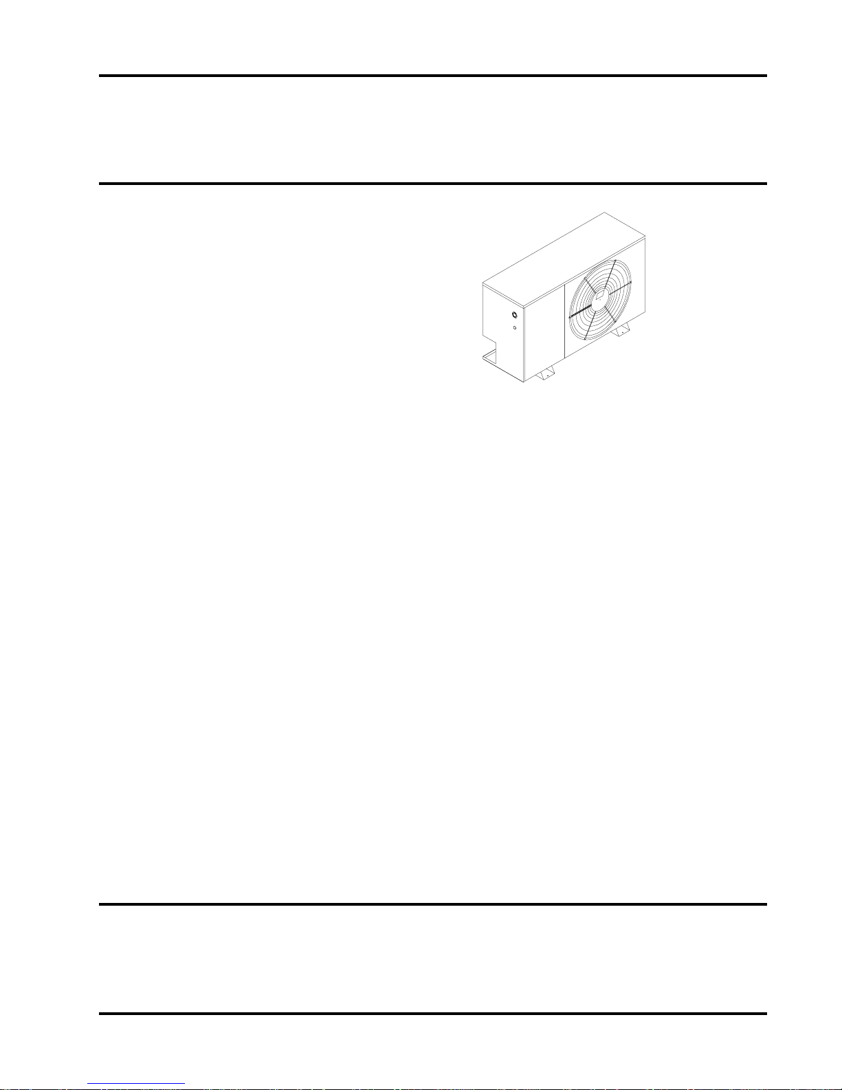
Installation Instructions
Outdoor Condensing
Section
Models: CTHAC181-A CTHAC181-D
CTHAC241-A CTHAC241-D
CTHAC301-A CTHAC301-D
CTHAC361-A CTHAC361-G
CTHAC421-A CTHAC421-E
CTHAC421-F CTHAC421-G
CTHAC481-A CTHAC481-B
CTHAC481-E CTHAC481-E
CTHAC481-G CTHAC601-A
CTHAC601-B CTHAC601-E
CTHAC601-F CTHAC601-G
For Use With:
Matching Indoor Blower Coil Units and
Matching Add On Coil Units Only
Manual No.: 2100-292
Date: 12-19-96
Page 2

Contents
Split Air Conditioner General Information.................. 1
Split Air Conditioner Model Nomenclature................ 1
Application and Location............................................. 3
General..................................................................... 3
Shipping Damage ..................................................... 3
Application ................................................................ 3
Location .................................................................... 3
Mounting Unit Outside on Slab................................. 3
Important Installer Note ............................................ 3
Installing Refrigerant Tubing..................................... 3
Sweat Style Tubing Connections: Sweat
Indoor Unit and Sweat Outdoor Unit......................... 4
Wiring Instructions....................................................... 7
General..................................................................... 7
Control Circuit Wiring ............................................... 7
Option Controls ............................................................ 8
Installation Instructions — CMA-1 ............................ 8
Installation Instructions — CMA-2 ............................ 9
Installation Instructions — CMA-4 ............................ 9
Installation Instructions — CMA-5 .......................... 10
Installation Instructions — CMA-6 .......................... 10
Installation Instructions — CMA-11..........................11
Charging Instructions ................................................ 12
Pressure Service Ports ........................................... 12
System Start-Up (Indoor Units
Without Expansion Valves)..................................... 12
Service ........................................................................ 13
Service Hints .......................................................... 13
Fan Blade Setting Dimensions ............................... 13
FIGURES
Figure 1 .................................................................... 1
Figure 2 .................................................................... 3
Figure 3 .................................................................... 4
Figure 4 .................................................................... 4
Figure 5 .................................................................... 8
Figure 6 .................................................................... 8
Figure 7 .................................................................... 9
Figure 8 .................................................................... 9
Figure 9 .................................................................. 10
Figure 10 ................................................................ 10
Figure 11..................................................................11
Figure 12 ................................................................ 13
TABLES
Table 1...................................................................... 1
Table 2...................................................................... 1
Table 3...................................................................... 2
Table 4...................................................................... 3
Table 5...................................................................... 6
Table 6...................................................................... 7
Table 7.................................................................... 12
Table 8.................................................................... 12
Table 9.................................................................... 13
Table 10.................................................................. 14
Table 11 .................................................................. 14
Table 12.................................................................. 15
Table 13.................................................................. 15
Table 14.................................................................. 16
Table 15.................................................................. 16
Table 16.................................................................. 17
Page 3
Split Air Conditioner General Information
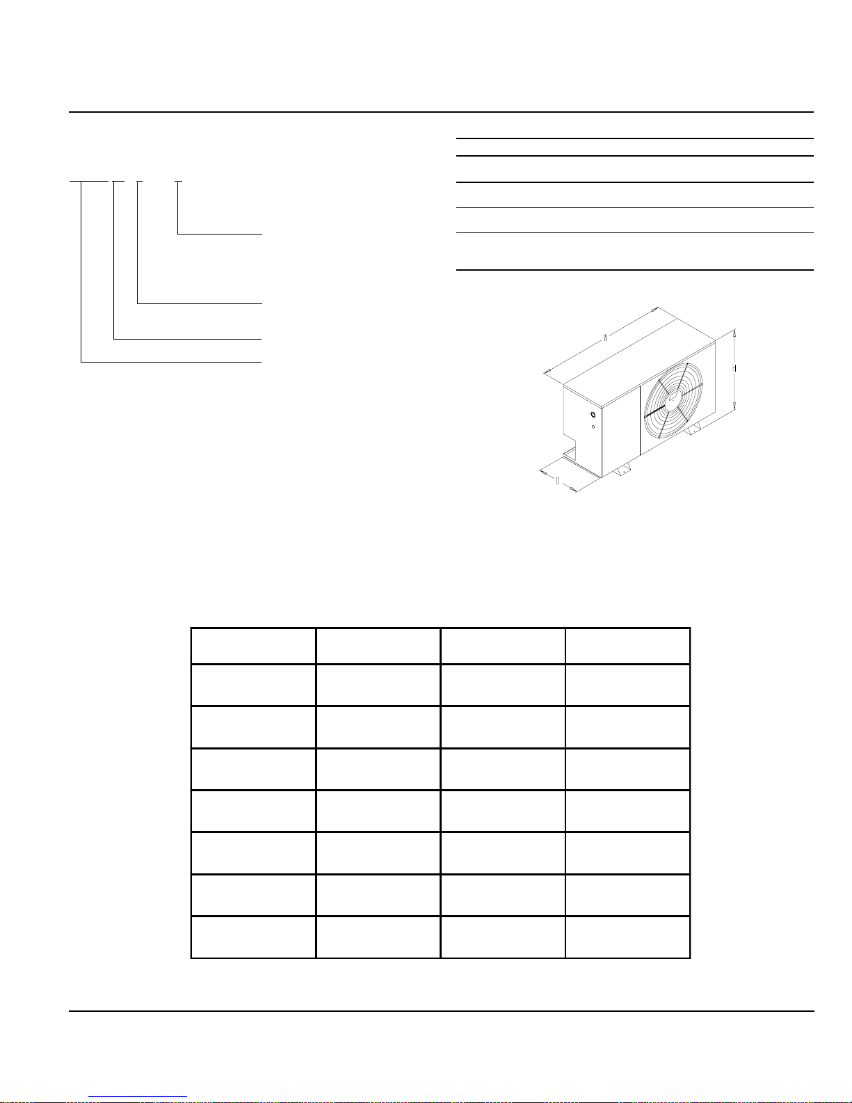
Split Air Conditioner Model Nomenclature
CTHAC 36 1 - A
Electrical Characteristics
A - 230/208-60-1
B - 230/200-60-3
D - 240/220-50-1
E - 220/200-50-3
F - 415/380-50-3
G - 220/200-50-1
Modification Code
Capacity -- 3 Ton or
Approx. 36,000 BTU
Basic Model Number
Table 1 — Dimensions
Model No. Width Depth Height
CTHAC181
CTHAC241
CTHAC301
CTHAC361
CTHAC421
CTHAC481 50" 15" 32"
CTHAC601
“W” “D” “H”
40" 15" 26"
45" 15" 26"
MIS-617
Figure 1
TABLE 2 – Rated CFM and Air Flow Data (Wet Coil – Cooling)
Co nd ensi ng Un it
Model Number
CTHAC181
CTHAC201
CTHAC301
CTHAC361
CTHAC421 FCP42 1225 0.078
CTHAC461
CTHAC601
Evapor ator Coil
Model Number CFM
FCP24
CEVA018
FCP24
CEVA024
FCP30
CEVA030
FCP36
CEVA036
FCP48
CEVA048
FCP60
CEVA060
600
600
800
800
1000
1000
1200
1200
1600
1600
2000
2000
System Orifice
Required
0.051
0.050
0.059
0.061
0.065
0.063
0.072
0.065
0.079
0.080
0.090
0.090
Page 1
Manual 2100-292
Page 4
Table 3 — Specifications
MODELS CTHAC181-A CTHAC241-A CTHAC301-A CTHAC361-A CTHAC421-A
Electrical Rating (60HZ/V/Ph) 230/208-1 230/208-1 230/208-1 230/208-1 230/208-1
Operating Voltage Range 197 - 253 197 - 253 197 - 253 197 - 253 197 - 253
Minimum Circuit Ampacity 15 1 5 1 9 2 0 2 5
Field Wire Size 14 1 4 1 2 1 2 1 0
Q
Delay Fuse Maximum or Circuit Breaker 20 2 0 3 0 3 0 40
R
T otal Unit Amps 230/208 7.9/8.6 10.2/11.4 13.4/14.0 14.5/15.8 19.1/19.6
COMPRESSOR
Volts 230/208 230/208 230/208 230/208 230/208 230/208
Rated Load Amps 6.8/7.5 9.1/10.3 12.3/12.9 13.4/14.7 17.6/18.1
Branch Circuit Selection Current 8.6 10.3 13.7 14.7 18.1
Lock Rotor Amps 230/208 49/49 56/56 75/75 82/82 105/105
Crankcase Heat None Immersion Type
FAN MOTOR AND CONDENSER
Fan Motor — HP/ RPM 1/6 - 825 1/4 - 825
Fan Motor — Amps 1.1 1.5
Fan — Diameter / CFM 20" - 2,000 24" - 2,600
SWEAT CONNECT SYSTEM
Suction Line Size ID 5/8" 3/4" 3/4" 3/4" 7/8"
Liquid Line Size ID 1/4" 3/8" 3/8" 3/8" 3/8"
Factory Charge R-22 Oz. 73 oz. 79 oz. 84 oz. 96 oz. 102 oz.
SHIPPING WEIGHT — Lbs. 155 155 180 180 250
Q
75º C copper wire size
R
Maximum time delay fuse or HACR type circuit breaker
Table 3 — Specifications (continued)
MODELS CTHAC481-A CTHAC481-B CTHAC601-A CTHAC601-B
Electrical Rating (60HZ/V/Ph) 230/208-1 230/208-3 230/208-1 230/208-3
Operating Voltage Range 197 - 253 187 - 253 197 - 253 187 - 253
Minimum Circuit Ampacity 26 17 35 21
Field Wire Size 10 12 8 10
Q
Delay Fuse Maximum or Circuit Breaker 45 25 60 3 5
R
Total Unit Amps 230/208 19.4/2 1.0 12.8/13 .4 22.7/2 6.7 15.3/17.2
COMPRESSOR
Volts 230/208 230/208 230/208 230/208
Rated Load Amps 230/208 17.9/1 9.5 11.3/11.9 21.2/25.2 13.8/15.7
Branch Circuit Selection Current 19.5 12.6 26.3 15.7
Lock Rotor Amps 230/208 102/102 91/91 135/135 150/150
Crankcase Heat Immersion Type None
FAN MOTOR AND CONDENSER
Fan Motor — HP / RPM
Fan Motor — Amps
Fan — Diameter
SWEAT CONNECT SYSTEM
Suction Line Size ID 7/8" 7/8" 7/8" 7/8"
Liquid Line Size ID 3/8" 3/8" 3/8"
Factory Charge R-22 Oz. 155 oz. 155 oz. 153 oz. 153 oz.
SHIPPING WEIGHT — Lbs. 250 250 255 255
Q
75º C copper wire size
R
Maximum time delay fuse or HACR type circuit breaker
1/4 - 825
1.5
24" - 2,600
Page 2
Manual 2100-292
Page 5

Table 4 — Specifications
MODELS CTHAC181-D CTHAC241-D CTHAC301-D CTHAC361-G CTHAC421-G CTHAC421-E CTHAC421-F
Electrical Rating (50HZ/V/Ph) 240/220-1 240/220-1 240/220-1 220/200-1 220/200-1 220/200--3 415/380-3
Operating Voltage Range 198 - 254 198 - 254 198 - 254 180 - 242 180 - 242 180 - 242 342 - 456
Minimum Circuit Ampacity 12 16 17 28 32 20 11
Field Wire Size 14 14 12 10 8 12 14
Q
Delay Fuse Maximum or Circuit Breaker 15 25 30 45 50 30 15
R
Total Unit Amps 9.6 12.8 14.9 21.2 23.0 14.8 8.1
Control Circuit
COMPRESSOR
Volts 240/220 240/220 240/220 220/200 220/200 220/200 415/380
Rated Load Amps 8.1 11.3 13.4 19.7 21.5 13.3 6.6
Branch Circuit Selection Current 8.1 11.3 13.7 21.1 23.7 14.7 7.0
Lock Rotor Amps 45.0 65.0 80.7 108.0 116.0 92.0 46.0
Crankcase Heat Immersion Type
FAN MOTOR AND CONDENSER
Fan Motor — HP / RPM 1/ 4- 825 1/4 - 825
Fan Motor — Amps 1.5 1.5
Fan — Diameter / CFM 20" - 2,000 24" - 2,600
SWEAT CONNECT SYSTEM
Suction Line Size ID 5/8" 3/4" 3/4" 3/4" 7/8" 7/8" 7/8"
Liquid Line Size ID 1/4" 3/8" 3/8" 3/8" 3/8" 3/8" 3/8"
Factory Charge R-22 Oz. 73 oz. 79 oz. 84 oz. 96 oz. 102 oz. 102 oz. 102 oz.
SHIPPING WEIGHT — Lbs. 155 155 180 180 180 250 250
Q
75º C copper wire size
R
Maximum time delay fuse or HACR type circuit breaker
S
For high voltage control circuit options consult factory
24 Volt
R
Table 4 — Specifications (continued)
MODELS CTHAC481-G CTHAC481-E CTHAC481-F CTHAC481-G CTHAC601-E CTHAC601-F
Electrical Rating (50HZ/V/Ph) 220/200-1 220/200-3 415/380-3 220/200-1 220/200-3 415/380-3
Operating Voltage Range 180 - 220 180 - 242 342 - 456 180 - 220 180 - 242 342 - 456
Minimum Circuit Ampacity 38 23 13 40 27 1 5
Field Wire Size 8 10 14 8 8 14
Q
Delay Fuse Maximum or Circuit Breaker 60 40 20 6 0 45 20
R
T otal Unit Amps 25.9 16.0 9.0 29.7 18.5 10.3
Control Circuit
COMPRESSOR
Volts 220/200 220/200 415/380 220/200 220/200 415/380
Rated Load Amps 24.4 14.5 7.5 28.2 17.0 8.8
Branch Circuit Selection Current 28.8 17.3 9.0 30.1 20.5 10.2
Lock Rotor Amps 13 8 10 6 53 178 12 4 62
Crankcase Heat Immersion Type
FAN MOTOR AND CONDENSER
Fan Motor — HP / RPM
Fan Motor — Amps
Fan — Diameter
SWEAT CONNECT SYSTEM
Suction Line Size ID 7/8" 7/8" 7/8" 7/8" 7/8" 7/8"
Liquid Line Size ID 3/8" 3/8" 3/8" 3/8" 3/8" 3/8"
Factory Charge R-22 Oz. 155 oz. 155 oz. 155 oz. 153 oz. 153 oz. 153 oz.
SHIPPING WEIGHT — Lbs. 250 250 250 255 255 255
Q
75º C copper wire size
R
Maximum time delay fuse or HACR type circuit breaker
S
For high voltage control circuit options consult factory
24 Volt
R
1/4 - 825
1.5
24" - 2,600
Page 3
Manual 2100-292
Page 6
Application and Location
General
These instructions explain the recommended method to install the
air cooled remote type condensing unit, the interconnecting
refrigerant tubing and the electrical wiring connections to the unit.
The condensing units are to be used in conjunction with the
matching evaporator coils or evaporator blower units for comfort
cooling applications as shown in the specification sheet.
These instructions and any instructions packaged with any separate
equipment required to make up the entire air conditioning system
should be carefully read before beginning the installation. Note
particularly “Starting Procedure” and any tags and/or labels
attached to the equipment.
While these instructions are intended as a general recommended
guide, they do not supersede any national and/or local codes in any
way. Authorities having jurisdiction should be consulted before the
installation is made.
Shipping Damage
Upon receipt of equipment, the carton should be checked for
external signs of shipping damage. If damage is found, the
receiving party must contact the last carrier immediately,
preferably in writing, requesting inspection by the carrier’s agent.
Application
Size of unit for a proposed installation should be based on heat
loss calculation and air duct sizing made according to methods of
Air Conditioning Contractors of America. The air duct should be
installed in accordance with the Standards of the National Fire
Protection Association for the Installation of Air Conditioning and
Ventilating Systems of Other Than Residence Type, NFPA 90A,
and Residence Type Warm Air Heating and Air Conditioning
Systems, NFPA 90B. Where local regulations are at a variance
with instructions, installer should adhere to local codes.
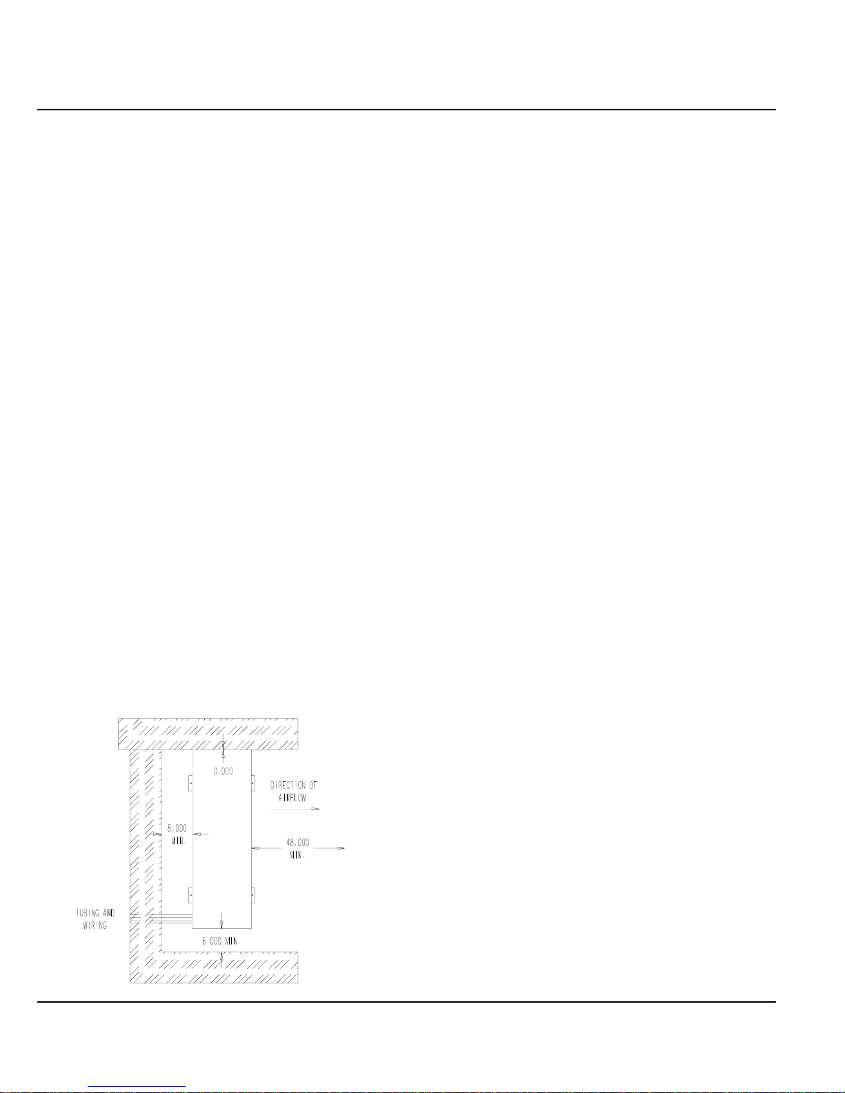
Location
Figure 2 — Installation Clearance
The condensing unit is designed to be located outside with free and
unobstructed condenser air inlet and discharge. It must also permit
access for service and installation. Condenser air enters the coil
and discharges. Refrigerant and electrical connections are made
from the rear of the unit as shown in Figure 2 with electrical
service access.
Mounting Unit Outside on Slab
A solid level base or platform, capable to support the unit’s
weight, must be set at the outdoor unit predetermined location. The
base should be at least two inches larger than the base dimensions
of the unit and at least two inches higher than surrounding grade
level. The required unit minimum installed clearances must be
maintained as called out in Figure 2 when locating and setting the
base.
Remove the unit from its shipping carton and position the unit on
the prepared base or platform.
Do not attach the unit or its base to the building structure to avoid
the transmission of noise into the occupied area.
NOTE: These units employ internally sprung compressors;
therefore, it is not necessary to remove or loosen the base
mounting bolts on the compressor prior to operation.
Consideration should be given to the electrical and tubing
connections when placing the unit to avoid unnecessary bends or
length of material.
Important Installer Note
For improved start-up performance, wash the indoor coil with a
dishwater detergent.
NOTE: ALL DIMENSIONS
IN INCHES
Page 4
Manual 2100-292
Installation Refrigerant Tubing
The information that follows on installing refrigerant tubing and
for changing the system orifice (if required) covers applications
listed in the front of this installation instruction only. Although
other indoor units may be of similar construction, the installation
instructions for these units should be consulted for proper
installation of those units prior to installation.
Page 7

Figure 3 — Installing Refrigerant Tubing
Sweat Style Tubing Connections: Sweat
Indoor Unit and Sweat Outdoor Unit
Use only refrigeration grade (dehydrated and sealed) copper
tubing. Care must be taken to insure that the tubing is kept clean
and dry before and during installation. Do not remove the plugs
from the tubing ends, coil connections or base valves until the
connection is ready to be brazed.
The suction line must be insulated with a minimum of 3/8"
Armaflex or equivalent before cutting and making connections.
Step 1. Being careful not to kink, route both the suction line and
liquid line between the indoor unit and outdoor unit. Use
a tubing bender to make any necessary bends in tubing.
When necessary to bend the insulated tube suction line,
cut the insulation around its circumference at a distance
far enough beyond the point of the bend so as to clear the
tubing bender. Slip the insulation back together and
vapor seal the joint with tape. Coil any excess tubing in a
horizontal place with the slope of the tubing toward the
condensing unit. See Figure 3.
Step 2. The tubing ends should be cut square. Make sure it is
round and free of burrs at the connecting ends. Clean
the tubing to prevent contaminants from entering the
system.
NOTE: Do not braze line to units! If orifice needs to be
changed, change out orifice first.
If the orifice does not have to be changed, skip the
instructions outlined further in Step 3 and proceed to
Step 8.
Step 3. Disassemble Flow Control Assembly by turning
body hex.
Step 4. If existing orifice has not dropped out of the body when
disassembled, remove by using a pin or paper clip.
Discard this original orifice.
Step 5. Insert proper sized orifice fully into the flow control
body with rounded “bullet” nose towards the unit as
shown. Insure the orifice stays inserted in body before
connecting mating half. See chart in the outdoor unit
installation instructions for proper size.
CAUTION
Be sure there is no dirt introduced into the
flow control —orifice assembly. Be sure to
install the orifice with the bullet nose pointing
in the proper direction as shown in Figure 4.
Failure to do so will result in improper
operation.
CAUTION
1. Be careful not to tear the insulation when
pushing it through hole in masonry or frame
walls. 2. When sealing the tube opening in
house wall, use a soft material to prevent tube
damage and vibration transmission. 3. Avoid
excessive bending in any one place to avoid
kinking.
Figure 4 — Flow Control Assembly Field Orifice
Replacement Instructions
Step 6. Thread assembly halves together by hand to insure
proper mating of threads and tighten until bodies
“bottom” or a definite resistance is felt.
Step 7. Using a marker pen or ink pen, mark a line lengthwise
from the union nut to the bulkhead. Then tighten an
additional 1/6 turn (or 1 hex flat). The misalignment of
the line will show the amount the assembly has been
tightened. This final 1/6 turn is necessary to insure the
formation of the leakproof joint.
Page 5
Manual 2100-292
Page 8

Step 8. Wrap a wet rag around the copper stub before brazing.
Step 9. Flux the copper tube and insert into the stub. Braze the
joint using an alloy of silver or copper and phosphorus
with a melting temperature above 1,100° F for copper
to copper joints. The phosphorus will act as a flux,
therefore, no flux will be required.
A copper-silver alloy with a high silver content should
be used when iron or steel material is involved in the
joint. These alloys require the use of silver solder flux.
Alloys containing phosphorus should not be used with
iron or steel. Phosphorus reacts with the iron, forming
iron phosphate which is extremely brittle.
CAUTION
1. Brazing alloys with a melting temperature
below 700° F should not be used. 2. Lead-tin
or tin-antimony solders should not be used
due to their low melting point and necessity
for corrosive fluxes.
To further prevent the formation of copper oxide inside
the tubing, dry nitrogen may be purged through the
refrigerant system during brazing.
WARNING
Never purge or pressurize a system with
oxygen. An explosion and fire will result.
Step 10. After brazing, quench with wet rag to cool the joint and
remove any flux residue.
Step 11. Leak test all connections using an electronic leak
detector or a halide torch.
Step 12. Evacuate suction line, liquid line and indoor unit
through outdoor unit base valves.
Step 13. Open both the suction and liquid base valves to the
fully open position. Refer to section later in installation
instructions for details on setting proper system charge.
Table 5— Tubing Chart
Basic Refrigerant Line Length (Ft.)
Condensing 0 - 20 21 - 60 61 - 100
Unit Model Liquid Suction Liquid Suction Liquid Suction
CTHAC181 1/4" 5/8" 1/4" 5/8" 3/8" 3/4"
CTHAC241 3/8" 5/8" 3/8" 3/4" 3/8" 3/4"
CTHAC301 3/8" 5/8" 3/8" 3/4" 3/8" 3/4"
CTHAC361 3/8" 5/8" 3/8" 3/4" 1/2" 7/8"
CTHAC421 3/8" 3/4" 3/8" 7/8" 1/2" 7/8"
CTHAC481 3/8" 7/8" 3/8" 7/8" 1/2" 1-1/8"
CTHAC601 3/8" 7/8" 3/8" 7/8" 1/2" 1-1/8"
Page 6
Manual 2100-292
Page 9

Wiring Instructions
General
All wiring must be installed in accordance with the National
Electrical Code and local codes. In Canada, all wiring must be
installed in accordance with the Canadian Electrical Code and in
accordance with the regulations of the authorities having
jurisdiction. Power supply voltage must conform to the voltage
shown on the unit serial plate. A wiring diagram of the unit is
attached to the inside of the electrical cover. The power supply
shall be sized and fused according to the specifications supplied.
A ground lug is supplied in the control compartment for
equipment ground.
The unit rating plate lists a “Maximum Time Delay Fuse” or
“HACR Type” circuit breaker that is to be used with the
equipment. The correct size must be used for proper circuit
protection and also to assure that there will be no nuisance tripping
due to the momentary high starting current of the compressor
motor.
Control Circuit Wiring
For split systems, the minimum control circuit wiring gauge
needed to insure proper operation of all controls in both indoor and
outdoor units will depend on two factors.
1. The rated VA of the control circuit transformer.
2. The maximum total distance of the control circuit wiring. (This
is the distance between the wall thermostat to the indoor unit
plus the distance between the indoor unit to the outdoor unit.)
The following table should be used to determine proper gauge
of control circuit wiring required.
Table 6— Control Circuit Wiring
Rated VA of Transformer Distance of
Control Circuit Secondary Control Circuit
Transformer FLA @ 24V Wiring in Feet
40 1.6
50 2.1 16 gauge - 100
65 2.7 16 gauge - 85
Maximum Total
20 gauge - 65
18 gauge - 90
16 gauge - 145
14 gauge - 230
20 gauge - 45
18 gauge - 60
14 gauge - 160
12 gauge - 250
20 gauge - 40
18 gauge - 55
14 gauge - 135
12 gauge - 210
Example: 1. Control circuit transformer rated at 40VA.
2. Maximum total distance of control circuit wiring
85 feet.
From Table 6, minimum of 18 gauge wire should be used in the
control circuit wiring.
For control circuit transformers rated other then those listed, use
the next lower rated transformer listed.
Example: 1. Control circuit transformer rated at 55VA.
From table use 50VA transformer.
Page 7
Manual 2100-292
Page 10

Optional Controls
SK109 Low
Voltage Start Kit
CMA-5 Compressor
Time Delay Relay
CMA-1 High
Pressure
Control Lockout
Relay
MIS-592
CMA-6Llow Ambient
Fan Cycling Control
Terminal Block
Installation Instructions — CMA-1
Disconnect all power to unit. Remove control panel cover.
Step 1. Mount lockout relay in position shown in Figure 5.
Step 2. Disconnect yellow low voltage (Y) wire at compressor
contactor coil or (Y1) at optional CMA-5 and reconnect
to terminal #4 of the lockout relay.
Step 3. Connect yellow wire from terminal #3 of the lockout
relay to the (Y) terminal of the compressor contactor
coil or (Y1) at optional CMA-5. This is the terminal
that the wire was removed from in Step 2.
Step 4. Route high (red) pressure switch wires up through the
bushing in the bottom of the control panel. Connect the
high pressure switch wires between terminal #5 of the
lockout relay and the (Y) terminal of the compressor
contactor coil or (Y1) at optional CMA-5.
Step 5. Remove service port cap on the discharge line. Install
the high pressure switch on the discharge line with the
flare tee adapter that is brazed to the high pressure
switch. Check for pressure at the flare tee dill valves
after installation to insure that the dill valve in the unit
service port was depressed by the flare tee connector.
Check for leaks at the flare tee connectors. Replace
service port cap on the flare tee service port and tighten.
CMA-2 Low Pressure Control Assembly
CMA-4 High and Low Pressure Control Assembly
CMA-11 Dual Pressure and Low Ambient Fan Cycling
Control Assembly
Figure 5 — Component Mounting Location
MIS-592
Step 6. Recheck wiring. See Figure 6. Check for proper
operation of the unit by energizing in cooling mode for
at least 5 minutes. The unit should not go into lockout.
Step 7. Replace all panels and covers. This completes
installation.
MIS-597
Figure 6 — Installation Instructions for
CMA-1 High Pressure Control
Page 8
Manual 2100-292
Page 11

Installation Instructions — CMA-2
Disconnect all power to unit. Remove control panel cover.
Step 1. Snap control assembly into control panel as shown in
Figure 5.
Step 2. Disconnect yellow low voltage (Y) wire at compressor
contactor coil or (Y1) at optional CMA-5 and reconnect
to terminal #4 of the lockout relay.
Step 3. Connect yellow wire from terminal #3 of the low
pressure bypass TDR to the (Y) terminal of the
compressor contactor coil or (Y1) at optional CMA-5.
This is the terminal that the wire was removed from in
Step 2.
Step 4. Connect the black wire from terminal H of the low
pressure bypass TDR to the common (C) side of the
compressor contactor coil.
Step 5. Route low (blue) pressure switch wires up through the
bushing in the bottom of the control panel. Connect low
pressure switch wires between terminals #1 and #3 of
the low pressure bypass TDR.
Step 6. Remove service port caps on the suction line. Install the
low pressure switch on the suction line with the flare
tee adapter that is brazed to the low pressure switch.
Check for pressure at the flare tee dill valves after
installation to insure that the dill valve in the unit
service port was depressed by the flare tee connector.
Check for leaks at the flare tee connectors. Replace
service port caps on the flare tee service ports and
tighten.
Step 7. Recheck wiring. See Figure 7. Check for proper
operation of the unit by energizing in heating or cooling
mode for at least 5 minutes. The unit should not go into
lockout.
Step 8. Replace all panels and covers. This completes
installation.
Installation Instructions — CMA-4
Disconnect all power to unit. Remove control panel cover.
Step 1. Snap control assembly into control panel as shown in
Figure 5.
Step 2. Disconnect yellow low voltage (Y) wire at compressor
contactor coil or (Y1) at optional CMA-5 and
reconnect to terminal #4 of the lockout relay.
Step 3. Connect yellow wire from terminal #3 of the low
pressure bypass TDR to the (Y) terminal of the
compressor contactor coil or (Y1) at optional CMA-5.
This is the terminal that the wire was removed from in
Step 2.
Step 4. Connect the black wire from terminal H of the low
pressure bypass TDR to the common (C) side of the
compressor contactor coil.
Step 5. Route high (red) and low (blue) pressure control wires
up through the bushing in the bottom of the control
panel. Connect low pressure control wires between
terminals #1 and #3 of the low pressure bypass TDR.
Step 6. Connect the high pressure control wires between
terminal #5 of the lockout relay and terminal #1 of the
low pressure bypass TDR.
Step 7. Remove service port caps on both the suction and
discharge lines. Install the high pressure control on the
discharge line with the flare tee adapter that is brazed
to the high pressure switch. Install the low pressure
control on the suction line. Check for pressure at the
flare tee dill valves after installation to insure that the
dill valve in the unit service port was depressed by the
flare tee connector. Check for leaks at the flare tee
connectors. Replace service port caps on the flare tee
service ports and tighten.
Step 8. Recheck wiring. Refer to Figure 8. Check for proper
operation of the unit by energizing in heating or
cooling mode for at least 5 minutes. The unit should
not go into lockout.
Step 9. Apply “This unit equipped with CMA-4 control
module” label to inside of inner control panel cover
above wiring diagram. Leave these instructions in
the unit.
Step 10. Replace all panels and covers. This completes
installation.
Figure 7 — Installation Instructions for
CMA-2 Low Pressure Control
MIS-596
MIS-595
Figure 8 — Installation Instructions for
CMA-4 High and Low Pressure Control
Page 9
Manual 2100-292
MIS-595
Page 12

Installation Instructions — CMA-5
Installation Instructions — CMA-6
Disconnect all power to the unit. Remove control panel cover.
Step 1. Mount compressor TDR in position shown in Figure 5
with screw provided.
Step 2. Disconnect yellow low voltage (Y) wire at the
compressor contactor coil and reconnect to the Y1 or #3
terminal of the TDR.
Step 3. Connect yellow wire from terminal (Y) of the TDR to
the (Y) terminal of the compressor contactor coil. This
is the terminal that the wire was removed from in
Step 2.
Step 4. Recheck wiring. Refer to Figure 9. Energize unit.
Compressor should start. Remove power and reapply.
Compressor should not start until the 5 minute time
delay has expired.
Step 5. Apply “This unit equipped with CMA-5 control
module” label to inside of the inner control panel cover
above wiring diagram.
Step 6. Replace all panels and covers. This completes
installation.
Disconnect all power to unit. Remove control panel inner and
outer cover.
Step 1. Mount terminal block in position shown in Figure 5.
Step 2. Disconnect black high voltage outdoor motor lead from
compressor contactor and reconnect to terminal block.
Step 3. Route low ambient control wires up through the
bushing in the bottom of the control panel. Connect the
low ambient control wires between the terminal block
and T2 of the compressor contactor.
Step 4. Remove service port cap on discharge line. Install the
low ambient control on the discharge line with the flare
tee adapter that is brazed to the low ambient control.
Check for pressure at the flare tee dill valve after
installation to insure that the dill valve in the unit
service port was depressed by the flare tee connector.
Check for leaks at the flare tee connectors. Replace
service port cap on the flare tee service port and tighten.
Step 5. Recheck wiring. See Figure 10. Check for proper
operation of the unit by energizing in cooling mode.
The condenser fan motor should not run until the
discharge pressure has exceeded 300 PSI. Should the
discharge pressure fall below 200 PSI while running,
the condenser fan motor will de-energize until the head
pressure builds to 300 PSI.
Figure 9 — Installation Instructions for
CMA-5 Compressor Time Delay Relay
MIS-598
Step 6. Apply “This unit equipped with CMA-6 control
module” label to the inside of the control panel cover
above the wiring diagrams.
Step 7. Replace all panels and covers. This completes
installation.
MIS-594
Figure 10 — Installation Instructions for
CMA-6 Low Ambient Fan Cycling Control
Page 10
Manual 2100-292
Page 13

Installation Instructions — CMA-11
Disconnect all power to unit. Remove control panel inner cover.
Step 1. Snap control assembly into control panel as shown in
Figure 5.
Step 2. Disconnect yellow low voltage (Y) wire at compressor
contactor coil or (Y1) at optional CMA-5 and reconnect
to terminal #4 of the lockout relay.
Step 3. Connect the black wire from terminal H of the low
pressure bypass TDR to the common (C) side of the
compressor contactor coil.
Step 4. Connect yellow wire from terminal #1 or (Y) of the low
pressure bypass relay to the (Y) terminal of the
compressor contactor coil or (Y1) at optional CMA-5.
This is the terminal that the wire was removed from in
Step 2.
Step 5. Route high (red) and low (blue) pressure switch wires
up through the bushing in the bottom of the control
panel. Connect the high pressure switch wires between
terminal #5 of the lockout relay and terminal #1 of the
low pressure bypass TDR.
Step 6. Connect low pressure switch wires between terminals
#1 and #3 of the low pressure bypass TDR.
Step 10. Recheck wiring. Refer to Figure 11. Energize unit in
first stage cooling. Compressor should start. Run the
unit for at least 5 minutes. The unit should not go into
lockout. The condenser fan motor should not run until
the discharge pressure has exceeded 300 PSI. Should
the discharge pressure fall below 200 PSI while
running, the condenser fan motor will de-energize until
the head pressure builds to 300 PSI.
Step 11. Apply “This unit equipped with CMA-11 control
module” label to the inside of the inner control panel
cover above the wiring diagram.
Step 12. Replace all panels and covers. This completes
installation.
Step 7. Disconnect black high voltage outdoor motor lead from
compressor contactor and reconnect to terminal block.
Step 8. Route low ambient control wires up through the
bushing in the bottom of the control panel. Connect the
low ambient control wires between the terminal block
and T2 of the compressor contactor.
Step 9. Remove service port caps on both the suction and
discharge lines. Install the high pressure switch and low
ambient control on the discharge line with the flare tee
adapter that is brazed to the controls. Install the low
pressure switch on the suction line. Check for pressure
at the flare tee dill valves after installation to insure that
the dill valve in the unit service port was depressed by
the flare tee connector. Check for leaks at the flare tee
connectors. Replace service port caps on the flare tee
service ports and tighten.
MIS-593
Figure 11 — Installation Instructions for CMA-11
Dual Pressure and Low Ambient Fan
Cycling Control
Page 11
Manual 2100-292
Page 14

Charging Instructions
Pressure Service Ports
High and low pressure service ports are installed on all units so
that the system operating pressures can be observed. Pressure
tables can be found later in the manual covering all models. It is
imperative to match the correct pressure table to the unit by model
number.
System Start-Up (Indoor Units Without
Expansion Valves)
Step 1. Close disconnect switch(es) and set the thermostat to
cool and the temperature to the highest setting.
Step 2. Check for proper airflow across the indoor coil by
referring to indoor unit installation.
Step 3. Connect the service gauges and allow the unit to run for
at least 10 minutes or until pressures are stable. Check
pressures to the system pressure table attached to the
outdoor unit service panel. For optimum system
performance, go to Step 4.
Step 4. Install a thermometer on the suction line approximately
6" to 10" from the compressor. Optimum system
performance will occur with a refrigerant charge
resulting in a suction line superheat as determined from
the following calculations.
A. Measure outdoor air dry bulb temperature ________ºF
B. Measure indoor air wet bulb temperature ________ºF
C. Measure suction pressure ________PSIG
D. Measure suction line temperature ________ºF
E. Determine optimum system superheat
from Table 9 using outdoor air dry bulb
(Step B) and indoor air wet bulb (Step A) ________ºF
F. Determine saturated suction temperature
from suction pressure using Table 10 ________ ºF
G. Determine system superheat:
Suction line temperature (Step D) ________ºF
- Saturated suction temperature (Step F) - ________ºF
= System superheat = _______ºF
H. Adjust the system superheat (Step G) to the optimum
system superheat (Step E) by adding charge to lower the
superheat or removing charge to raise the superheat.
I. Check final system operating pressures to the system
pressure tables as was done in Step 3.
Table 7— System Superheat
Outdoor Ambient Return Air Temperature
Temperature º F — Wet Bulb
(º F Dry Bulb) 59 63 67 71
105 1 1 5 —
95 1 3 (8) 20
90 1 7 14 26
85 3 9 19 33
80 8 14 25 39
75 10 20 30 42
Table 8— Saturated Suction Temperature (R-22)
Saturated Suction
Suction Pressure PSIG Temperature (º F)
50 26
53 28
55 30
58 32
61 34
63 36
65 38
67 39
70 41
73 43
76 45
79 47
82 49
86 51
Page 12
Manual 2100-292
Page 15

Service
Service Hints
1. Caution homeowner to maintain clean air filters at all times.
Also, not to needlessly close off supply and return air registers.
This reduces air flow through the system, which shortens
equipment service life, as well as, increasing operating costs.
2. Check all power fuses or circuit breakers to be sure that they are
the correct rating.
3. Periodic cleaning of the outdoor coil to permit full and
unrestricted air flow circulation is essential.
Fan Blade Setting Dimensions
Shown in Figure 12 are the correct fan blade setting dimensions for
proper air delivery across the outdoor coil.
Any service work requiring removal or adjustment in the fan and/
or motor area will require that the dimensions below be checked
and blade adjusted in or out on the motor shaft accordingly.
A
Figure 12 — Fan Blade
Table 9— Fan Blade Setting Dimensions
Model Dimension A
CTHAC181
CTHAC241
CTHAC301
CTHAC361
CTHAC421
CTHAC481 3-1/4"
CTHAC601
3"
Page 13
Manual 2100-292
Page 16

TABLE 10 – CTHAC181
Return Air
Indoor Section
FCP24
CEVA018
Low side pressure ± 2 PSIG
High side pressure ± 5 PSIG
Tables are based upon rated CFM (airflow) across the evaporator coil. If there is any doubt as to correct
operation charge being in the system, the charge should be removed, system evacuated, and recharged to
serial plate instructions.
Temperature Pressure 75 80 85 90 95 100 105 110 115
75° DB/62° WB
80° DB/67° WB
85° DB/72° WB
75° DB/62° WB
80° DB/67° WB
85° DB/72° WB
Low Side 70 72 74 76 78 80 82 84 86
High Side 187 202 217 231 246 260 275 290 304
Low Side 75 77 79 82 84 86 88 91 93
High Side 192 207 222 237 252 267 282 297 312
Low Side 81 83 85 88 90 92 95 97 99
High Side 198 214 229 245 261 277 293 308 324
Low Side 60 64 67 71 74 78 81 84 88
High Side 180 196 211 227 243 259 274 290 306
Low Side 65 68 72 75 79 82 86 89 93
High Side 185 201 218 234 250 266 282 298 315
Low Side 69 73 77 81 85 89 93 96 100
High Side 191 208 225 242 259 276 293 310 327
TABLE 11 – CTHAC241
Return Air
Indoor Section
FCP24
CEVA024
Low side pressure ± 2 PSIG
High side pressure ± 5 PSIG
Tables are based upon rated CFM (airflow) across the evaporator coil. If there is any doubt as to correct
operation charge being in the system, the charge should be removed, system evacuated, and recharged to
serial plate instructions.
Temperature Pressure 75 80 8 5 9 0 95 100 105 110 115
75° DB/62° WB
80° DB/67° WB
85° DB/72° WB
75° DB/62° WB
80° DB/67° WB
85° DB/72° WB
Low Side 67 70 73 75 78 81 83 86 89
High Side 198 213 228 243 258 273 288 303 318
Low Side 72 75 78 80 83 86 88 91 94
High Side 203 219 234 249 265 280 296 311 326
Low Side 78 81 84 86 89 92 94 97 100
High Side 211 227 242 258 274 290 305 321 337
Low Side 62 65 68 71 74 77 80 83 86
High Side 198 214 229 244 260 275 291 306 321
Low Side 67 70 73 76 79 82 85 88 91
High Side 204 220 235 251 267 283 298 314 330
Low Side 71 75 78 81 85 88 92 95 99
High Side 211 227 244 260 276 292 308 324 340
Page 14
Manual 2100-292
Page 17

TABLE 12 – CTHAC301
Return Air
Indoor Section
FCP30
CEVA030
Low side pressure ± 2 PSIG
High side pressure ± 5 PSIG
Tables are based upon rated CFM (airflow) across the evaporator coil. If there is any doubt as to correct
operation charge being in the system, the charge should be removed, system evacuated, and recharged to
serial plate instructions.
Temperature Pressure 75 80 8 5 9 0 95 100 105 110 115
75° DB/62° WB
80° DB/67° WB
85° DB/72° WB
75° DB/62° WB
80° DB/67° WB
85° DB/72° WB
Low Side 64 67 70 73 76 79 82 85 88
High Side 202 216 230 245 259 273 287 302 316
Low Side 69 72 75 78 81 84 87 90 93
High Side 208 222 237 251 266 280 295 310 324
Low Side 73 77 80 84 87 90 94 97 100
High Side 215 230 245 260 275 290 305 320 335
Low Side 61 64 67 70 73 76 79 82 85
High Side 196 211 226 241 256 271 286 301 316
Low Side 66 69 72 75 78 81 84 87 90
High Side 201 217 232 248 263 278 294 309 325
Low Side 70 74 77 81 84 87 91 94 98
High Side 207 223 239 256 272 288 304 320 336
TABLE 13 – CTHAC361
Return Air
Indoor Section
FCP36
CEVA036
Low side pressure ± 2 PSIG
High side pressure ± 5 PSIG
Tables are based upon rated CFM (airflow) across the evaporator coil. If there is any doubt as to correct
operation charge being in the system, the charge should be removed, system evacuated, and recharged to
serial plate instructions.
Temperature Pressure 75 80 8 5 9 0 95 100 105 110 115
75° DB/62° WB
80° DB/67° WB
85° DB/72° WB
75° DB/62° WB
80° DB/67° WB
85° DB/72° WB
Low Side 65 67 69 72 74 76 79 81 83
High Side 185 200 216 231 247 262 278 293 308
Low Side 70 72 74 77 79 81 83 86 88
High Side 190 206 221 237 253 269 284 300 316
Low Side 74 77 80 82 85 88 90 93 96
High Side 196 221 229 245 262 278 295 311 328
Low Side 61 64 67 69 72 75 77 80 83
High Side 197 210 224 238 252 365 280 293 307
Low Side 66 69 72 74 77 80 82 85 88
High Side 202 216 230 245 259 273 287 301 316
Low Side 71 74 77 80 83 86 89 92 95
High Side 209 224 238 253 268 281 297 311 326
Page 15
Manual 2100-292
Page 18

TABLE 14 – CTHAC421
Return Air
Indoor Section
FCP42
Low side pressure ± 2 PSIG
High side pressure ± 5 PSIG
Tables are based upon rated CFM (airflow) across the evaporator coil. If there is any doubt as to correct
operation charge being in the system, the charge should be removed, system evacuated, and recharged to
serial plate instructions.
Temperature Pressure 75 80 8 5 9 0 95 100 105 110 115
75° DB/62° WB
80° DB/67° WB
85° DB/72° WB
Low Side 68 70 72 75 77 79 81 84 86
High Side 184 199 215 231 247 263 278 294 310
Low Side 73 75 77 80 82 84 86 89 91
High Side 188 204 221 237 253 269 285 301 318
Low Side 78 81 83 86 88 90 93 95 97
High Side 194 211 228 245 262 279 296 313 330
TABLE 15 – CTHAC481
Return Air
Indoor Section
FCP48
CEVA048
Low side pressure ± 2 PSIG
High side pressure ± 5 PSIG
Tables are based upon rated CFM (airflow) across the evaporator coil. If there is any doubt as to correct
operation charge being in the system, the charge should be removed, system evacuated, and recharged to
serial plate instructions.
Temperature Pressure 75 80 8 5 9 0 95 100 105 110 115
75° DB/62° WB
80° DB/67° WB
85° DB/72° WB
75° DB/62° WB
80° DB/67° WB
85° DB/72° WB
Low Side 70 72 74 77 79 81 84 86 88
High Side 191 205 220 234 249 263 278 293 307
Low Side 75 77 79 82 84 86 89 91 93
High Side 195 210 225 240 255 270 285 300 315
Low Side 81 83 85 88 90 92 95 97 99
High Side 202 218 233 249 264 278 295 310 326
Low Side 63 65 67 70 70 74 76 79 81
High Side 173 189 206 222 239 256 272 289 305
Low Side 68 70 72 75 77 79 82 84 86
High Side 177 194 211 228 245 262 279 296 313
Low Side 72 75 78 80 83 86 88 91 94
High Side 183 201 219 236 254 272 289 307 325
Page 16
Manual 2100-292
Page 19

TABLE 16 – CTHAC601
Return Air
Indoor Section
FCP60
CEVA060
Low side pressure ± 2 PSIG
High side pressure ± 5 PSIG
Tables are based upon rated CFM (airflow) across the evaporator coil. If there is any doubt as to correct
operation charge being in the system, the charge should be removed, system evacuated, and recharged to
serial plate instructions.
Temperature Pressure 75 80 85 90 95 100 105 110 115
75° DB/62° WB
80° DB/67° WB
85° DB/72° WB
75° DB/62° WB
80° DB/67° WB
85° DB/72° WB
Low Side 68 70 72 75 77 79 82 84 86
High Side 194 211 228 246 26 3 280 298 315 332
Low Side 73 75 77 80 82 84 87 89 91
High Side 199 217 235 252 270 288 30 5 323 341
Low Side 79 81 83 86 88 90 93 95 97
High Side 207 225 243 261 279 297 31 5 333 351
Low Side 60 61 63 64 65 66 67 68 70
High Side 197 210 222 235 248 261 27 3 286 299
Low Side 64 65 67 68 70 72 73 75 76
High Side 202 215 228 241 254 267 28 0 293 306
Low Side 69 70 72 73 75 77 78 80 81
High Side 209 222 236 250 263 276 28 9 303 317
Page 17
Manual 2100-292
 Loading...