

Bard CompleteStat CS9B-THOA, CompleteStat CS9BE-THOA, CompleteStat CS9BE-THOCA, CompleteStat CS9B-THOCA, CS9B-THOA Advanced Programming & Features
...Page 1
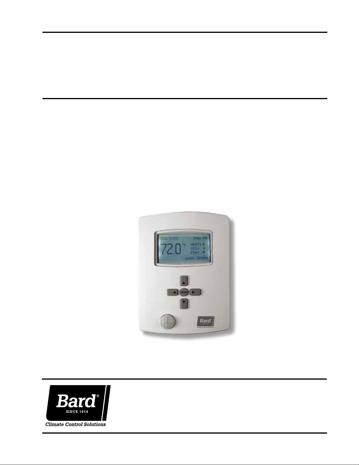
ADVANCED
PROGRAMMING & FEATURES
CompleteStat
Models:
CS9B-THOA
CS9B-THOCA
TM
Controller
CS9BE-THOA
CS9BE-THOCA
Bard Manufacturing Company, Inc.
Bryan, Ohio 43506
www.bardhvac.com
Manual: 2100-685
Supersedes: NEW
Date: 3-20-18
Page 1 of 18
Page 2

TABLE OF CONTENTS
INSTALLATION ........................................................3
Display Options .................................................. 3
BASIC OPERATION .................................................5
Operational Overviews ......................................... 5
Setting Date/Time ............................................... 5
Scheduling ........................................................ 6
Adjusting Standby Conditions .............................. 7
Temporary Temperature Override .......................... 7
Adjusting Temporary Temperature Override Time
Length ........................................................... 7
Staging Delay ..................................................... 8
Remote Sensors ................................................. 8
Remote Indoor Air Temperature Sensor .............. 8
Outdoor Air Temperature Sensor ........................ 8
Remote Occupancy Sensor ............................... 9
Leaving Air Temperature Sensor ........................ 9
Dehumidification Setup ....................................... 9
Temperature Limits ........................................... 10
Heating/Cooling Loop Configuration .................... 10
Indoor Blower Settings ...................................... 11
Alarms Feature ................................................. 12
Security Settings .............................................. 13
Trend Logs ....................................................... 14
Restart ......................................................... 15
Restore Factory Settings .................................... 16
BACnet Communications ................................... 16
Advanced Time Settings for BACnet
Applications .................................................. 17
Temperature Sensor Calibration .......................... 18
FIGURES
Figure 1 CompleteStat Home Screen Features .... 3
Figure 2 User Interface (Display) Option ............. 3
Figure 3 Motion/Occupancy Sensor Detection
Range ................................................ 4
Figure 4 Setting Date/Time ............................... 6
Figure 5 Scheduling Options ............................. 6
Figure 6 Setting Time Periods ........................... 6
Figure 7 Adjusting Standby Conditions ............... 7
Figure 8 Cancelling Termporary Override ............ 7
Figure 9 Adjusting Temporary Override Time
Length ............................................... 8
Figure 10 Adjusting Remote Temperature Sensor .. 8
Figure 11 Adjusting Dehumidification Settings ... 10
Figure 12 Adjusting Temperature Limits ............. 10
Figure 13 Minimum Setpoint Differential &
Heating/Cooling Proportional Bands .... 11
Figure 14 Adjusting Heating/Cooling
Proportional Bands and Integers ......... 11
Figure 15 Adjusting Blower Settings .................. 11
Figure 16 Setting Up Space Temp Alarms .......... 12
Figure 17 Setting Up Humidity Alarms ............... 12
Figure 18 Viewing Internal Alarms ..................... 12
Figure 19 Alarm Details .................................... 13
Figure 20 Temporarily Deactivating Locking User
Interface .......................................... 13
Figure 21 Cancelling Locking User Interface ....... 13
Figure 22 Accessing/Programming Areas of
Security ........................................... 14
Figure 23 Accessing/Changing Passwords ........... 14
Figure 24
Figure 25 Accessing Trend Logs ........................ 15
Figure 26 Programming New Trend Logs ............ 15
Figure 27 Programming New Trend Logs ............ 15
Figure 28 Initiating Restart ............................... 16
Figure 29 Setting Protocol and Parameters for
BACnet ............................................ 16
Figure 30 Accessing Device Instance, Name
and Location .................................... 17
TABLES
Table 1 UTC Offset Minutes Sample Time
Zones............................................... 18
Accessing/Adjusting Inactivity Setting ...
14
Manual 2100-685
Page 2 of 18
NOTE
Screenshots shown in this manual reflect
default settings (when applicable).
Page 3
INSTALLATION
NOTE: Follow the instructions provided in the latest version of CompleteStat Controller Installation, Operation &
Quick Start Guide 2100-684 before using this manual.
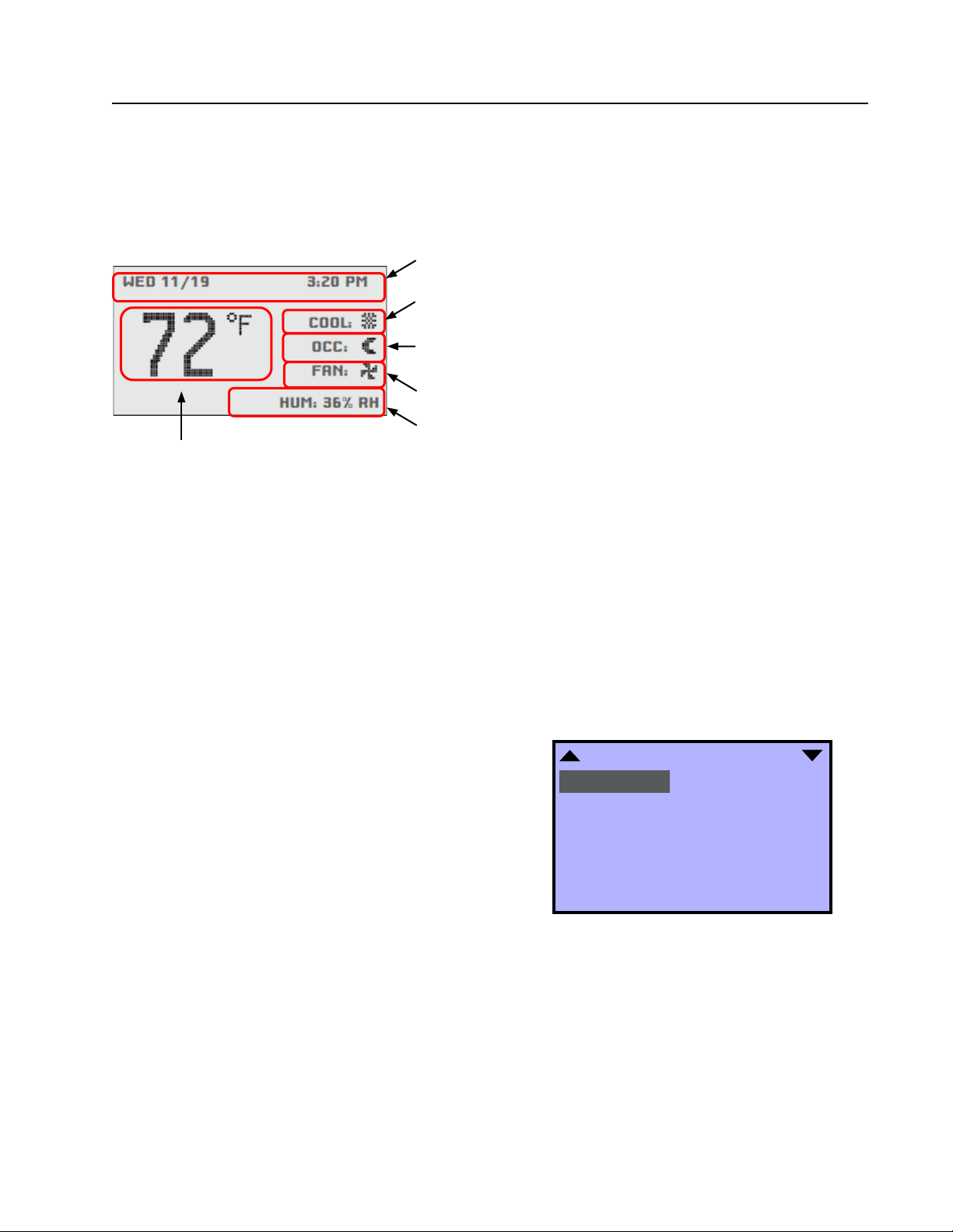
FIGURE 1
CompleteStat Home Screen Features
Date and Time Line: Reference or scheduling purposes
Current Operation Status: Cooling, Heating, Dehum or Off status, indicated
by “snowflake” icon, “heat waves” icon, “raindrop” icon or “OFF”.
Occupancy Status: Occupied, Unoccupied, or Temporary Override option,
indicated by “sun” icon, “moon” icon or “OVR” letters, respectively.
Fan Status: Fan blade icon, animated when “ON”.
System Information Rotation Values: “HUM” shows relative humidity (%),
Current Room Temperature
Degrees F or Degrees C
“CO2” shows ppm of carbon dioxide (if equipped with sensor) and “OAT”
shows outdoor air temperature degrees F or C (if equipped with sensor).
NOTE: Rotation Values will change approximately every
5 seconds. These values can be customized if desired.
NOTE: By default, controller will read temperature in
Fahrenheit. To temporarily toggle reading to Celcius,
press the ENTER button for more than 2 seconds. The
new scale will stay in place until repeated, or until
the controller is restarted. For permanent change, see
page 5 of the latest version of CompleteStat Controller
Installation, Operation & Quick Start Guide 2100-684.
Navigate the menus and change settings by pressing a
combination of the four arrow buttons and the ENTER
button.
• ENTER button to select and/or exit value editing
• UP or DOWN button to move among entries
• RIGHT or LEFT button to move among value fields
• LEFT button to return to the home screen
NOTE: If the screen includes up and down arrows in
the upper corners (as shown in Figure 2), additional
choices can be found by continuing to press the UP or
DOWN buttons.
NOTE: Access to the Main Menu, setpoint adjust and
system/occupancy/fan override may require a password.
Display Options
To adjust backlight, change rotation values and/or
activate temperature tenths:
1. Press RIGHT button to access Main Menu screen.
2. Press DOWN button to scroll to TECHNICIAN.
Press ENTER button.
3.
Controller will ask for password. Press UP and RIGHT
buttons to enter ‘BARD’. Press ENTER button.
4. Press DOWN button to scroll to ADVANCED. Press
ENTER button.
5. Press DOWN button to scroll to USER INTERFACE.
Press ENTER button.
6. Press DOWN button to highlight entry of choice
(see Figure 2).
FIGURE 2
User Interface (Display) Options
USER INTERFACE
BACKLIGHT: AUTO
CONTRAST: 40
DISPLAY BLANKING: NO
INACTIVITY (SECS): 120
ROTATION VALUES
SHOW TEMP TENTHS: NO
SHOW TIME & DATE: YES
7. Press ENTER button to select entry of choice.
8. Press UP or DOWN buttons to toggle between
adjustments (asterisks indicate default values):
• BACKLIGHT – Choose between AUTO* (turns
off after inactivity period), or ON
• CONTRAST – 30-63 (40*)
• DISPLAY BLANKING – YES/NO*
• INACTIVITY (SECS) – 5-600 (60*)
Manual 2100-685
Page 3 of 18
Page 4
• ROTATION VALUES – Choose to HIDE or
SHOW:
HUM (SHOW*)
OAT (HIDE*)
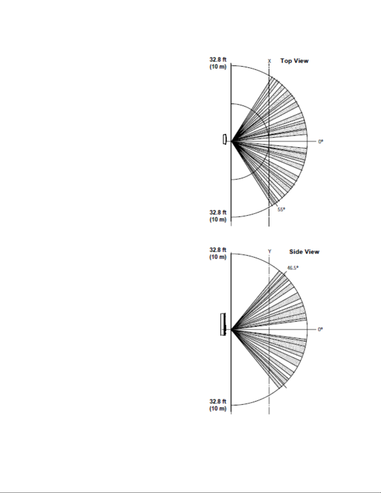
FIGURE 3
Motion/Occupancy Sensor Detection Range
U13 (SHOW*) – Non-CO
C02 (SHOW*) – CO
sensing models
2
sensing models
2
UI4 (HIDE*)
• SHOW TEMP TENTHS – Choose YES (allows
decimal temperature measurement) or NO*
• SHOW TIME & DATE – YES*/NO
• MODE – Choose between user interfaces:
o STANDARD* – User has all access, but
may need security code for certain areas.
o HOSPITALITY – User has simpler display,
limited menu. Mostly used in hotel rooms.
o LOCKED UI – User cannot access or
change ANY item within controller.
NOTE: Do not activate HOSPITALITY or
LOCKING UI until controller is completely
programmed. Deactivation is intentionally
difficult (see Security Settings on page 13).
9. Press ENTER button to save changes.
10. Press LEFT button to return to the Home screen.
Manual 2100-685
Page 4 of 18
Page 5

BASIC OPERATION
Operational Overviews
The factory-default settings will provide an intelligent,
“learning” temperature control.
CS9B(E)-THOA (non-CO
sensing capability) models
2
come standard with scheduling features; however, from
the factory, all the controllers are configured to have no
“occupied” periods. In this default configuration, the
CompleteStat is typically in an Unoccupied (moon icon)
mode enabling “setback” temperatures and disabling
ventilation unless the controller senses motion. After
sensing motion, the controller will enter a Temporary
Override (OVR) mode and will maintain “occupied”
temperatures and enable ventilation based on indoor
1
fan operation
until motion ceases for a specified length
of time (see Adjusting Temporary Override Time Length
on page 7). If the scheduling function is provided with
an “occupied” period, the scheduled Occupied (sun
icon) mode will also maintain “occupied” temperatures
and enable ventilation based on indoor fan operation
1
until the end of the programmed scheduled period.
• Adaptive Start intelligent temperature control
has been enabled as a factory default. Controller
will “learn” the typical occupancy schedules
without having to manually program them into the
scheduling feature and will automatically bring
the space to “occupied” setpoints before the
occupants arrive. If, however, no one arrives during
a learned occupancy period, the CompleteStat
will revert to the setback temperatures within a
specified period of time (see Adjusting Temporary
Override Time Length on page 7).
• Optimum Start intelligent temperature control
has also been enabled as a factory default. If
scheduled occupied periods are desired, the
CompleteStat will automatically begin to track
the amount of time necessary to bring the space
from “setback” temperatures to “occupied”
temperatures. Based on recent run-times, the
controller will adjust to ensure “occupied”
setpoints are reached before the occupants arrive.
1
CS9B(E)-THOA (non-CO2 sensing capability) models
will only activate ventilation (“A” terminal) when the
indoor fan is running and in an “occupied” condition.
To activate constant ventilation during occupied
periods, the indoor fan will have to be placed into
constant run mode during “occupied” conditions (see
Indoor Blower Settings on page 11).
CS9B(E)-THOCA (CO
sensing capability) models come
2
standard with scheduling features; however, from the
factory, all the controllers are configured to have no
“occupied” periods. In this default configuration, the
CompleteStat is typically in an Unoccupied (moon icon)
mode enabling “setback” temperatures and disabling
ventilation unless the controller senses motion. After
sensing motion, the controller will enter a Temporary
Override (OVR) mode and will maintain “occupied”
temperatures and enable ventilation based upon CO
2
content
until motion ceases for a specified length of
2
time (see Adjusting Temporary Override Time Length
on page 7). If the programmability feature is enabled,
the scheduled Occupied (sun icon) mode will also
maintain “occupied” temperatures and enable constant
ventilation based on CO
content2 until the end of the
2
programmed scheduled period.
• Adaptive Start intelligent temperature control
has been enabled as a factory default. Controller
will “learn” the typical occupancy schedules
without having to manually program them into the
scheduling feature and will automatically bring
the space to “occupied” setpoints before the
occupants arrive. If, however, no one arrives during
a learned occupancy period, the CompleteStat
will revert to the setback temperatures within a
specified period of time (see Adjusting Temporary
Override Time Length on page 7).
• Optimum Start intelligent temperature control
has also been enabled as a factory default. If
scheduled occupied periods are desired, the
CompleteStat will automatically begin to track
the amount of time necessary to bring the space
from “setback” temperatures to “occupied”
temperatures. Based on recent run-times, the
controller will adjust to ensure “occupied”
setpoints are reached before the occupants arrive.
² CS9B(E)-THOCA (CO
only activate ventilation (“A” terminal) when the CO
levels have exceeded the CO
“occupied” condition. To adjust CO
sensing capability) models will
2
setpoints and in an
2
level setpoint,
2
2
see Setpoints in latest version of CompleteStat
Controller Installation, Operation & Quick Start Guide
2100-684.
Setting Date/Time
To enter the current date and time from the Home
screen:
1. Press RIGHT button to access Main Menu screen.
2. Press DOWN button to scroll to DATE/TIME. Press
ENTER button.
3. Press ENTER button to select DATE (see Figure 4
on page 6).
4. Press RIGHT, UP or DOWN buttons to adjust
existing month, day and/or year.
5. Press ENTER button to save selection(s).
Manual 2100-685
Page 5 of 18
Page 6

6. Press DOWN button to scroll to TIME. Press
ENTER button.
7. Press RIGHT, UP or DOWN buttons to adjust
existing hour, minute, second and/or AM/PM.
8. Press ENTER button to save selection(s).
9. Press LEFT button to return to the Home screen.
FIGURE 4
Setting Date/Time
FIGURE 5
Scheduling Options
SCHEDULE
ENTIRE WEEK [MON-SUN]
WEEKDAYS [MON-FRI]
WEEKEND [SAT-SUN]
INDIVIDUAL DAYS
HOLIDAYS
DATE/TIME
DATE: JAN 7 2017
TIME: 2:08:39 AM
Scheduling
If desired, the CompleteStat can be manually
programmed to offer specific occupied/unoccuppied
time periods. During these scheduled time spans, the
controller will keep the space within the occupied and
unoccupied setpoints
To access scheduling from the Home screen:
1. Press RIGHT button to access Main Menu screen.
2. Press ENTER button to select SYSTEM.
3. Press DOWN button to scroll to SCHEDULE. Press
ENTER button.
4. Press UP or DOWN buttons to scroll through
schedule options (see Figure 5):
1
.
5 Press ENTER button to select specific schedule
option.
6. Press ENTER to select specific time period of
occupied/unoccupied (see Figure 6).
7. Press RIGHT button to access hours/minutes/
seconds/AM-PM.
8. Press UP or DOWN buttons to adjust as necessary.
9. Press RIGHT button to access period status.
Choice of ON (occupied), OFF (unoccupied) or
NULL (do not program this value). “NULL” is used
in certain commercial control platforms.
10. Press UP or DOWN buttons to adjust as necessary.
11. Press ENTER button to save scheduling
programming.
12. Repeat steps 6-13 as necessary to complete
scheduling time periods.
13. Press LEFT button to return to the Home screen.
FIGURE 6
Setting Time Periods
ENTIRE WEEK for a “7-Day” style of scheduling
• Up to six (6) separate occupied/unoccuppied
periods/day
WEEKDAYS
• Up to six (6) separate occupied/unoccuppied
periods/day
WEEKEND
• Up to six (6) separate occupied/unoccuppied
periods/day
INDIVIDUAL DAYS for specific day-customization
scheduling
• Up to six (6) separate occupied/unoccuppied
periods/day
HOLIDAYS for up to twelve (12) holiday exceptions
to the main scheduling
• Holidays will override to setback temperatures
for that specific date
Manual 2100-685
Page 6 of 18
WEEKDAYS
1: 12:00:00 AM ON
2: : :
3: : :
4: : :
5: : :
6: : :
[ > ] DELETES ENTRY
1
During scheduled OCC periods, if the controller does
not sense motion for a specific length of time, the
controller will allow the space to enter “standby”
conditions, where temperature may offset by up to
3°F for the duration of the OCC period. To adjust this
offset in degrees, or waiting period, see Adjusting
Standby Conditions.
Page 7

Adjusting Standby Conditions
Users may opt to adjust temperature offset, change
time length of waiting period or even disable standby
feature.
To change standby conditions parameters from the
Home screen:
1. Press RIGHT button to access Main Menu screen.
2. Press DOWN button to scroll to TECHNICIAN.
Press ENTER button.
3.
Controller will ask for password. Press UP and RIGHT
buttons to enter ‘BARD’. Press ENTER button.
4. Press ENTER button again to select APPLICATION.
5. Press DOWN button to scroll to ADDITIONAL
SETUP. Press ENTER button.
6. Press DOWN button to scroll to MOTION SENSOR.
Press ENTER button.
7. Press DOWN button to highlight the following
choices (see Figure 7):
• STATE (OCCUPIED/UNOCCUPIED)
• STANDBY (ENABLE/DISABLE)
• OFFSET (specify °F offset span)
• TIMER (specify time length of waiting period)
8.
Press ENTER button to select appropriate selection.
9. Press UP or DOWN buttons to enter specific
parameters.
10. Press ENTER button to save changes.
11. Press LEFT button to return to the Home screen.
FIGURE 7
Adjusting Standby Conditions
1. Press UP or DOWN buttons to access the current
temperature setpoint. “SET” will appear under
temperature reading.
2. Press UP or DOWN button again to adjust current
temperature setpoint to desired temperature.
3. Press ENTER or LEFT or RIGHT buttons to select
temporary setpoint change. OVR will appear in the
Occupancy Status line.
NOTE: If no “schedule” has been previously entered,
OVR will already be displayed in the “Occupancy
Status” line.
To cancel temporary override from Home screen:
1. Press LEFT button to highlight Current Operation
Status line.
2. Press DOWN button to highlight Occupancy Status
line. Press ENTER button.
3. Press ENTER button again to select OCC
OVERRIDE and highlight ON (see Figure 8).
4. Press UP or DOWN button to change from ON to
OFF.
5. Press ENTER button to select override
cancellation.
6. Press LEFT button to return to the Home screen.
NOTE: If no “schedule” has been entered, temperature
override will cancel, but OVR will remain in Occupancy
Status line.
FIGURE 8
Cancelling Temporary Override
OCCUPANCY OVERRIDE
OCC OVERRIDE: ON
MOTION SENSOR
STATE: OCCUPIED
STANDBY: ENABLE
~ OFFSET: 4°F
~ TIMER (MINS): 60
Temporary Temperature Override
Any changes to temperature from the Home screen
will result in a temporary “override” which will last for
a programmable length of time (factory default is 10
minutes).
To change temperatures temporarily from the Home
screen:
Adjusting Temporary Temperature Override Time Length
To adjust temporary override time length from Home
screen:
1. Press RIGHT button to access Main Menu screen.
2. Press ENTER button to select SYSTEM.
3. Press DOWN button to scroll to OCC OVRIDE (see
Figue 9 on page 8). Press ENTER button.
4. Press UP or DOWN buttons to adjust time (5
minute increments, maximum 2000 minutes).
5. Press ENTER button to select new override time
limit.
Manual 2100-685
Page 7 of 18
Page 8

6. Press LEFT button to return to the Home screen.
FIGURE 9
Adjusting Temporary Override Time Length
the baseplate of the controller and configure the
CompleteStat as noted below.
To add a remote temperature sensor or change the
parameters of a remote sensor from the Home screen:
SYSTEM
SYSTEM ENABLE: AUTO
OCCUPANCY: SCHEDULE
OCC OVRIDE (MINS): 240
SCHEDULE
Staging Delay (Only applicable to two stage
configuration)
While the typical delay between stages consists of 1°F,
a length of time in minutes can be customized.
To access/change staging time delay from the Home
screen:
1. Press RIGHT button to access Main Menu screen.
2. Press DOWN button to scroll to TECHNICIAN.
Press ENTER button.
3.
Controller will ask for password. Press UP and RIGHT
buttons to enter ‘BARD’. Press ENTER button.
4. Press ENTER button again to select APPLICATION.
5. Press DOWN button to scroll to ADDITIONAL
SETUP. Press ENTER button.
6. Press DOWN button to scroll to STAGING. Press
ENTER button.
7. Press ENTER button again to select STG DELAY
(MINS).
8. Press UP or DOWN buttons to adjust time.
9. Press ENTER button to save new STG DELAY entry.
1. Press RIGHT button to access Main Menu screen.
2. Press DOWN button to scroll to TECHNICIAN.
Press ENTER button.
3.
Controller will ask for password. Press UP and RIGHT
buttons to enter ‘BARD’. Press ENTER button.
4. Press ENTER button again to select APPLICATION.
5. Press DOWN button to scroll to ADDITIONAL
SETUP. Press ENTER button.
6. Press DOWN button to scroll to SENSORS. Press
ENTER button.
7. Press DOWN button to scroll to SPACE TEMP (see
Figure 10). Press ENTER button.
8. Press UP or DOWN buttons to toggle between
SPACE TEMP entries:
• ONBOARD – Integral temp sensor reading only
• LOWEST – Controller will read lowest of two
readings
• HIGHEST – Controller will read highest of two
readings
• AVERAGE – Averaged reading between remote
thermistor and onboard sensor
• REMOTE – Thermistor reading only
9. Press ENTER button to save new SPACE TEMP
entry.
10. Press LEFT button to return to the Home screen.
FIGURE 10
Adding Remote Temperature Sensor
10. Press LEFT button to return to the Home screen.
Remote Sensors
External sensors can be added to perform as a remote
indoor air temperature sensor, outdoor air temperature
sensor, remote occupancy sensor or leaving air
temperature sensor.
Remote Indoor Air Temperature Sensor
Bard 8403-062 Remote Indoor Air Temperature
Sensor can have multiple functions. The controller
can be configured to look at the remote as the primary
temperature sensor or as an averaged reading between
the remote and the onboard sensor, or to choose
between the highest of the two readings or the lowest
of the two sensors. Attach the 10k ohm thermister
to the two terminals marked “REM” and “GND” on
Manual 2100-685
Page 8 of 18
SENSOR SETUP
IN 4: NOT USED
IN 8: NOT USED
IN 9: NOT USED
SPACE TEMP: ONBOARD
~ IN 1 IS ONBOARD
Outdoor Air Temperature Sensor
Bard 8403-061 Outdoor Air Temperature Sensor can
be used to simply show outdoor temperatures, or to
configure auxiliary heat control strategy (see Heat Pump
Applications in the latest version of CompleteStat
Controller Installation, Operation & Quick Start Guide
2100-684). Attach the 10k ohm thermister to the two
Page 9

terminals marked “OAT” and “GND” on the baseplate
of the controller and configure the CompleteStat as
noted below.
To add an outdoor temperature sensor or change the
parameters of an outdoor sensor from the Home screen:
1. Press RIGHT button to access Main Menu screen.
2. Press DOWN button to scroll to TECHNICIAN.
Press ENTER button.
3.
Controller will ask for password. Press UP and RIGHT
buttons to enter ‘BARD’. Press ENTER button.
4. Press ENTER button again to select APPLICATION.
5. Press DOWN button to scroll to ADDITIONAL
SETUP. Press ENTER button.
6. Press DOWN button to scroll to SENSORS. Press
ENTER button.
7. Press DOWN button to scroll to IN 8. Press ENTER
button.
8. Press UP or DOWN buttons to toggle between IN 8
entries:
• NOT USED – Default
• OCCUPANCY – Remote sensor
9. Press ENTER button to save new IN 8 entry.
10. Press LEFT button to return to the Home screen.
Leaving Air Temperature Sensor
Bard 8301-014 Leaving Air Temperature Sensor can
be added, however, access to the temperature readings
will only be available through a BACnet platform. No
configuration of the controller is necessary. Attach the
sensor leads to terminals marked “LAT” and “GND” on
the baseplate of the controller.
7. Press ENTER button again to access IN 4 entry.
8. Press UP or DOWN buttons to toggle between IN 4
entries:
• NOT USED – Default
• OUTSIDE AIR TEMP – Remote sensor
9. Press ENTER button to save new IN 4 entry.
10. Press LEFT button to return to the Home screen.
Remote Occupancy Sensor
Remote occupancy sensor can be used to remote or
enhance occupancy coverage. While Bard does not
currently offer a branded sensor as a part number, the
Sensorswitch
TM
WV-16-R or CM-9-R Series sensor—or
any equivalent close-on-occupancy switch—would work.
The sensor works in conjunction with the onboard
sensor to provide additional coverage; any motion
sensed by either sensor will activate occupancy. Attach
the close-on-occupancy switch leads to terminals
marked “ROS” and “GND” on the baseplate of the
controller and configure as noted below.
To add a remote occupancy sensor or change the
parameters of an occupancy sensor from the Home
screen:
1. Press RIGHT button to access Main Menu screen.
2. Press DOWN button to scroll to TECHNICIAN.
Press ENTER button.
3.
Controller will ask for password. Press UP and RIGHT
buttons to enter ‘BARD’. Press ENTER button.
4. Press ENTER button again to select APPLICATION.
5. Press DOWN button to scroll to ADDITIONAL
SETUP. Press ENTER button.
6. Press DOWN button to scroll to SENSORS. Press
ENTER button.
Dehumidification Setup
The CompleteStat can be configured to dehumidify, but
only through a specific HVAC system that has builtin dehumidification capabilities (i.e., hot gas reheat
coil). Upon humidity rise past preset setpoint, the “D”
terminal will become energized.
To access the dehumidification option from the Home
screen:
1. Press RIGHT button to access Main Menu screen.
2. Press DOWN button to scroll to TECHNICIAN.
Press ENTER button.
3.
Controller will ask for password. Press UP and RIGHT
buttons to enter ‘BARD’. Press ENTER button.
4. Press ENTER button again to select APPLICATION.
5. Press DOWN button to scroll to ADDITIONAL
SETUP. Press ENTER button.
6. Press DOWN button to scroll to HUMIDITY. Press
ENTER button.
7. Press ENTER button again to choose
DEHUMIDIFICATION.
8. Press ENTER button again to highlight current
DEHUM choice (default DISABLE).
9. Press UP or DOWN button to toggle ENABLE (see
Figure 11 on page 10).
10. Press ENTER button to save choice.
11. Press DOWN button to scroll through
DEHUMIDIFICATION entries:
• ALLOW HTG DEHUM – Allows
dehumidification in heating
• DEHUM SETPT – The relative humidity (RH)
% setpoint
Manual 2100-685
Page 9 of 18
Page 10

• DEHUM SPAN – The amount of RH%
removal allowed past setpoint (5%RH default
minimum)
12. Press ENTER button on selected
DEHUMIDIFICATION entry.
8. Press ENTER button to save new limit choice.
9. Repeat steps 5 through 8 for remainder of change
to LIMITS.
10. Press LEFT button to return to the Home screen.
13. Press UP or DOWN button to toggle through
available entries or levels.
14. Press ENTER button to save specific entry
changes.
15. Repeat steps 11 through 14 for remainder of
DEHUMIDIFICATION entries.
16. Press LEFT button to return to the Home screen.
FIGURE 11
Adjusting Dehumidification Settings
DEHUMIDIFICATION
DEHUM: ENABLE
ALLOW HTG DEHUM: YES
DEHUM SETPT: 60%RH
DEHUM SPAN: 5%RH
Temperature Limits
Absolute limits can be set to ensure no user can raise/
lower occupied or unoccupied temperatures past
specific setpoints, or that setpoints cross specific
minimum differential margins.
To access/change temperature limits from the Home
screen:
1. Press RIGHT button to access Main Menu screen.
2. Press DOWN button to scroll to TECHNICIAN.
Press ENTER button.
3.
Controller will ask for password. Press UP and RIGHT
buttons to enter ‘BARD’. Press ENTER button.
4. Press DOWN button to scroll to LIMITS. Press
ENTER button.
5. Press UP or DOWN buttons to highlight appropriate
choice (see Figure 12):
• OCC MIN CLG
• OCC MAX HTG • MIN SETPT DIFF
• UNOCC MIN CLG • OAT HTG HIGH
• UNOCC MAX HTG
6. Press ENTER button to select appropriate choice.
7. Press UP or DOWN buttons to adjust limit
temperatures.
• COMP OAT CLG LOW
FIGURE 12
Adjusting Temperature Limits
LIMITS
OCC MIN CLG: 68°F
OCC MAX HTG: 74°F
UNOCC MIN CLG: 76°F
UNOCC MAX HTG: 68°F
COMP OAT CLG LOW: 0°F
MIN SETPT DIFF: 4°F
OAT HTG HIGH: 75°F
Heating/Cooling Loop Configuration
Heating/cooling proportional bands can be adjusted
(see Figure 13).
To access/change the PI Loop configurations from the
Home screen:
1. Press RIGHT button to access Main Menu screen.
2. Press DOWN button to scroll to TECHNICIAN.
Press ENTER button.
3.
Controller will ask for password. Press UP and RIGHT
buttons to enter ‘BARD’. Press ENTER button.
4. Press DOWN button to scroll to ADVANCED. Press
ENTER button.
5. Press DOWN button to scroll to LOOPS. Press
ENTER button.
6. Press DOWN button to highlight appropriate choice
(see Figure 14):
• COOL PROP – Cooling proportional band
(Default 2°F)
• HEAT PROP – Heating proportional band
(Default 2°F)
• COOLING INTG – Do not change from factory
default
• HEATING INTG – Do not change from factory
default
7. Press ENTER button to select appropriate choice.
8. Press UP or DOWN buttons to adjust setting.
9. Press ENTER button to save new setting.
10. Press LEFT button to return to the Home screen.
Manual 2100-685
Page 10 of 18
Page 11

FIGURE 13
Minimum Setpoint Differential & Heating/Cooling Proportional Bands
FIGURE 14
Adjusting Heating/Cooling Proportional Bands
and Integers
LOOP CONFIGURATION
COOL PROP: 2.0°F
HEAT PROP: 2.0°F
COOL INTG: 4/hr
HEAT INTG: 4/hr
Indoor Blower Settings
The indoor blower can be set for Auto or On in either
occupied or unoccupied conditions.
To access/change blower settings from the Home
screen:
1. Press LEFT button to highlight Current Operation
Status line.
2. Press DOWN button to highlight Fan Status line.
Press ENTER button to enter FAN MODES screen.
• UNOCC
ON: System fan will run continuously during
all operational modes
AUTO: System fan will operate during call for
cooling or heating, but will cycle off when no
compressor or no heating is needed (Default).
• OCC
ON: System fan will run continuously during
all operational modes
AUTO: System fan will operate during call for
cooling or heating, but will cycle off when no
compressor or no heating is needed (Default).
FIGURE 15
Adjusting Blower Settings
FAN MODES
UNOCC: AUTO
OCC: AUTO
3. Press UP or DOWN buttons again to scroll through
selections, adjust as necessary (see Figure 15):
Manual 2100-685
Page 11 of 18
Page 12

4. Press ENTER button to save changes to FAN
MODES selections.
5. Repeat steps 3 through 4 for additonal changes to
FAN MODES selections.
13. Press UP or DOWN buttons to toggle between
HUMIDITY ALARM entries (factory defaults shown
in Figure 17):
• LOW LIMIT
6. Press LEFT button to return to the Home screen.
Alarms Feature
High temperature, low temperature, high CO
and other specific anomalies will be recorded within an
internal page. Alarms may be set up and viewed and
deleted as necessary for serviceability
To set up alarms:
1. Press RIGHT button to access Main Menu screen.
2. Press DOWN button to scroll to TECHNICIAN.
Press ENTER button.
3.
Controller will ask for password. Press UP and RIGHT
buttons to enter ‘BARD’. Press ENTER button.
4. Press DOWN button to scroll to ALARMS. Press
ENTER button.
5. Press ENTER button again to select ALARM
SETUP.
6. Press ENTER button to select SPACE TEMP.
7. Press UP or DOWN buttons to scroll through
SPACE TEMP ALARM entries (factory defaults
shown in Figure 16):
• LOW LIMIT
• HIGH LIMIT
• DEADBAND
• DELAY (SECS)
1
levels
2
.
FIGURE 16
Setting Up Space Temp Alarms
• HIGH LIMIT
FIGURE 17
Setting Up Humidity Alarms
HUMIDITY ALARM
LOW LIMIT: 0%RH
HIGH LIMIT: 100%RH
14. Press ENTER button to select appropriate choice.
15. Press UP or DOWN buttons to adjust setting.
16. Press ENTER button to save new setting.
17. Press LEFT button to return to Home screen.
To view/delete internal alarms:
1. Press RIGHT button to access Main Menu screen.
2. Press DOWN button to scroll to TECHNICIAN.
Press ENTER button.
3.
Controller will ask for password. Press UP and RIGHT
buttons to enter ‘BARD’. Press ENTER button.
4. Press DOWN button to scroll to ALARMS. Press
ENTER button.
5. Press DOWN button to scroll to ALARM VIEWER.
Press ENTER button. Logged alarms will show with
brief description/date (see Figure 18).
SPACE TEMP ALARM
LOW LIMIT: 56ºF
HIGH LIMIT: 86ºF
DEADBAND: 2ºF
DELAY (SECS): 300
8. Press ENTER button to select appropriate choice.
9. Press UP or DOWN buttons to adjust setting.
10. Press ENTER button to save new setting.
11. Press LEFT button to return to ALARM SETUP.
12. Press DOWN button to scroll to HUMIDITY. Press
ENTER button.
Manual 2100-685
Page 12 of 18
FIGURE 18
Viewing Internal Alarms
ALARMS
¤ SPACE CO2 ALA 12/12
¤ SPACE CO2 ALA 12/09
¤ SPACE CO2 ALA 12/08
6. Press ENTER button to show more detailed
description of alarm (see Figure 19).
7. Press ENTER button to be given DELETE choice.
8. Press ENTER button to delete alarm.
9. Press LEFT button to return to the Home screen.
Page 13

1
When an internal alarm has been registered, a
“Service” indicator will begin flashing on the Home
screen. This does not interfere with normal operation
and will disappear once all alarms have been deleted.
FIGURE 19
Alarm Details
MON 12/12 7 27 AM
HEAT:
OCC:
FAN:
77
°F
To cancel locking user interface from Main Menu
screen:
1. Press RIGHT button to access Main Menu screen.
2. Press DOWN button to scroll to TECHNICIAN.
Press ENTER button.
3.
Controller will ask for password. Press UP and RIGHT
buttons to enter ‘BARD’. Press ENTER button.
4. Press DOWN button to scroll to ADVANCED. Press
ENTER button.
5. Press UP or DOWN buttons to scroll to USER
INTERFACE. Press ENTER button.
SERVICE CO2: 1259PPM
Security Settings
There are two locking styles of user interfaces (see
Display Options on page 3), five separate areas that can
be controlled by passwords and four individual levels of
security.
To deactivate locking user interface (HOSPITALITY or
LOCKED UI):
1. Press RIGHT button and ENTER button
simultaneously and hold for 5 seconds.
2. Press LEFT button (while still holding RIGHT and
ENTER buttons) and hold for 5 seconds.
3. Release RIGHT button (while continuing to hold
the LEFT and ENTER buttons) for 5 additional
seconds.
4. Once FLEXSTAT screen appears (as shown in
Figure 20), press DOWN button two spaces past
the TIME line (press DOWN button four times).
5. Press ENTER button to deactivate locking user
interface and return to Main Menu screen.
NOTE: This will only temporarily deactivate the locking
user interface.
FIGURE 20
Temporarily Deactivating Locking User Interface
6. Press UP or DOWN buttons to scroll to MODE (see
Figure 21). NOTE: MODE does not show up on
first screen. Continuing to press the UP or DOWN
button will display MODE.
7. Press ENTER button to select Mode.
8. Press UP or DOWN button to toggle to STANDARD.
9. Press ENTER button to save STANDARD mode.
10. Press LEFT button to return to the Home screen.
FIGURE 21
Cancelling Locking User Interface
USER INTERFACE
CONTRAST: 40
DISPLAY BLANKING: NO
INACTIVITY (SECS): 120
ROTATION VALUES
SHOW TEMP TENTHS: NO
SHOW TIME & DATE: YES
MODE: STANDARD
To access/program areas of security from Home screen:
1. Press RIGHT button to access Main Menu screen.
2. Press DOWN button to scroll to TECHNICIAN.
Press ENTER button.
3.
Controller will ask for password. Press UP and RIGHT
buttons to enter ‘BARD’. Press ENTER button.
FLEXSTAT
ABOUT
DATE: DEC 12 2017
TIME: 11:16:51 AM
4. Press DOWN button to scroll to SECURITY. Press
ENTER button.
5. Press ENTER button again to select ACCESS
LEVELS.
6. Press UP or DOWN buttons to scroll through
five access levels (see Figure 22 on page 14):
SETPOINT ADJ, MAIN MENU, SYSTEM MODE,
OCC OVERRIDE and FAN OCC/UNOCC.
7. Press ENTER button to enter a chosen access
level.
Manual 2100-685
Page 13 of 18
Page 14

8. Press UP or DOWN buttons to select among the
four levels of security for each access level: USER,
NONE, ADMIN or OPER.
FIGURE 23
Accessing/Changing Passwords
9. Press ENTER button to save choice.
10. Repeat steps 6 through 9 for each of the five
access levels.
11. Press LEFT button to return to the Home screen.
FIGURE 22
Accessing/Programming Areas of Security
ACCESS LEVELS
SETPOINT ADJ: USER
MAIN MENU: USER
SYSTEM MODE: USER
OCC OVERRIDE: USER
FAN OCC/UNOCC: USER
To access/change passwords from the Home screen:
1. Press RIGHT button to access Main Menu screen.
2. Press DOWN button to scroll to TECHNICIAN.
Press ENTER button.
3.
Controller will ask for password. Press UP and RIGHT
buttons to enter ‘BARD’. Press ENTER button.
4. Press UP or DOWN buttons to scroll to SECURITY.
Press ENTER button.
5. Press UP or DOWN button to scroll to
PASSWORDS. Press ENTER button.
PASSWORDS
USER:
OPERATOR:
0 0 0 0
0 0 0 0
ADMIN: B A R D
To access/change Inactivity (Secs) setting of controller
from the Home screen:
1. Press RIGHT button to access Main Menu screen.
2. Press DOWN button to scroll to TECHNICIAN.
Press ENTER button.
3.
Controller will ask for password. Press UP and RIGHT
buttons to enter ‘BARD’. Press ENTER button.
4. Press UP or DOWN buttons to scroll to ADVANCED
Press ENTER button.
5. Press UP or DOWN buttons to scroll to USER
INTERFACE. Press ENTER button.
6. Press UP or DOWN buttons to scroll to INACTIVITY
(see Figure 24). Press ENTER button.
7. Press UP or DOWN buttons to adjust amount of
seconds of inactivity.
8. Press ENTER button to save new time limit.
9. Press LEFT button to return to the Home screen.
6. Press UP or DOWN buttons to scroll through the
three levels of security passwords (see Figure 23):
USER, OPERATOR and ADMIN. ADMIN password
defaults to BARD.
7. Press ENTER button to select specific password.
8. Press UP, DOWN and RIGHT buttons to enter digits
to specific passwords.
9. Press ENTER button to save password.
10. Repeat steps 6 through 9 for each of the three
levels of security passwords.
11. Press LEFT button to return to the Home screen.
NOTE: After any password is given, the only delay to
enabling security programming will be the Inactivity
(Secs) setting of controller (60 seconds is default).
Once 60 seconds of button inactivity is realized,
security settings will go into effect.
NOTE: If Admin password is changed to “0000,” it will
inactivate all security passwords, and allow unlimited
access at all levels.
Manual 2100-685
Page 14 of 18
FIGURE 24
Accessing/Adjusting Inactivity Setting
USER INTERFACE
BACKLIGHT: AUTO
CONTRAST: 40
DISPLAY BLANKING: NO
INACTIVITY (SECS): 120
ROTATION VALUES
SHOW TEMP TENTHS: NO
SHOW TIME & DATE: YES
Trend Logs
The controller can be enabled to show a history log of
recorded information, specific to input sensors installed
on the unit. Space temperature and CO
been set up as a factory default logs, with 10-minute
samples taken continuously. Adjustments may be made
to duration and frequency of sampling, and logs may be
customized to show additional information.
levels have
2
Page 15

To access trend logs from the Home screen:
• AV1 –
1. Press RIGHT button to access Main Menu screen.
2. Press DOWN button to scroll to TECHNICIAN.
Press ENTER button.
3.
Controller will ask for password. Press UP and RIGHT
buttons to enter ‘BARD’. Press ENTER button.
4. Press UP or DOWN buttons to scroll to TREND
VIEWER. (NOTE: TREND VIEWER does not show
up on first screen. Continuing to press the UP or
DOWN button will display TREND VIEWER.) Press
ENTER button.
5. Press DOWN button to scroll to chosen log (see
FIgure 25).
FIGURE 25
Accessing Trend Logs
TL#1 – SPACE TEMP
JAN06 3:43AM, ENABLE
JAN06 3:43AM, 71.7
JAN06 3:53AM, 73.0
JAN06 4:04AM, 72.4
JAN06 4:14AM, 72.3
JAN06 4:24AM, 72.4
JAN06 4:34AM, 73.3
6. Press ENTER button to select log and view
recorded results.
7. Press LEFT button to return to the Home screen.
To program new trend logs from the Home screen:
1. Press RIGHT button to access Main Menu screen.
• AO1 –
• AI1 –
• BV1 –
• BO1 –
• BI1 –
9. Press ENTER button to save selection.
10. Press DOWN button to highlight LOG ENABLE.
Press ENTER button.
11. Press UP or DOWN button to toggle FALSE to
TRUE.
12. Press ENTER button to save TRUE setting.
13. Press DOWN button to highlight INTERVAL
(MINS). Press ENTER button.
14. Press UP or DOWN buttons to adjust minutes of
interval between readings.
FIGURE 26
Programming New Trend Logs
TREND LOGS
TREND1: TRUE
TREND2: FALSE
TREND3: FALSE
TREND4: FALSE
TREND5: FALSE
TREND6: FALSE
TREND7: FALSE
2. Press DOWN button to scroll to TECHNICIAN.
Press ENTER button.
3.
Controller will ask for password. Press UP and RIGHT
buttons to enter ‘BARD’. Press ENTER button.
4. Press DOWN button to scroll to ADVANCED. Press
ENTER button.
5. Press UP or DOWN buttons to scroll to TREND
LOGS. Press ENTER button.
6. Press DOWN button to highlight chosen trend logs
(see Figure 26):
• Trend1 is factory default set up to trend space
temp
• Trend2 – Trend8 are programmable
7. Press ENTER button to select chosen log and enter
setup screen.
8. Press DOWN button to highlight OBJECT REF (see
Figure 27). Press ENTER button.
FIGURE 27
Programming New Trend Logs
TREND #1
SPACE TEMPERATURE LOG
OBJECT REF: AI1
LOG ENABLE: TRUE
INTERVAL (MINS): 10
STOP W/FULL: FALSE
RESET COUNT: NO
COUNT: 252
15. Press ENTER button to save new setting.
16. Press LEFT button to return to the Home screen.
Restart
Should the controller exhibit erratic/haphazard
performance during programming or operation,
Manual 2100-685
Page 15 of 18
Page 16

a“soft-restart” function has been enabled into the
programming.
7. Press ENTER button to initiate (NOTE: Controller
will restart to Home screen).
To initiate a restart from the Home screen:
1. Press RIGHT button to access Main Menu screen.
2. Press DOWN button to scroll to TECHNICIAN.
Press ENTER button.
3.
Controller will ask for password. Press UP and RIGHT
buttons to enter ‘BARD’. Press ENTER button.
4. Press DOWN button to scroll to RESTART/
RESTORE. Press ENTER button.
5. Press ENTER button again to select RESTART (see
Figure 28).
FIGURE 28
Initiating Restart
RESTART / RESTORE
RESTART: NO
RESTORE FACTORY: NO
6. Press UP or DOWN buttons to choose from the
following options:
• NO (no restart made)
• WARM START (least intrusive, quickest
response)
BACnet Communications
The Bard CompleteStat is a native BACnet Advanced
Application Controller (B-AAC) and can simplify
networked zone control for many kinds of common
packaged HVAC equipment. The following section
addresses the needs of BACnet applications only.
Typical wiring for BACnet applications:
For MS/TP communications, connect the EIA-485
wiring to the –A and +B terminals on the base plate of
the controller.
For Ethernet, IP, and Foreign Device communications
(on “E” Models), plug an Ethernet cable directly into
the RJ-45 modular jack on the back of the controller.
To set protocol and parameters for BACnet
communications from the Home screen:
1. Press RIGHT button to access Main Menu screen.
2. Press DOWN button to scroll to TECHNICIAN.
Press ENTER button.
3.
Controller will ask for password. Press UP and RIGHT
buttons to enter ‘BARD’. Press ENTER button.
4. Press DOWN button to scroll to COMMUNICATION.
Press ENTER button.
5. Press ENTER button to select ACTIVE (see Figure
29).
FIGURE 29
Setting Protocol and Parameters for BACnet
• COLD START (comprehensive restart)
7. Press ENTER button to initiate (NOTE: Controller
will restart to Home screen).
Restore Factory Settings
If the controller becomes unmanageable due to
improper settings, the device can be reset to “factory”
settings by initiating a Restore Factory command.
To initiate a factory reset from the Home screen:
1. Press RIGHT button to access Main Menu screen.
2. Press DOWN button to scroll to TECHNICIAN.
Press ENTER button.
3.
Controller will ask for password. Press UP and RIGHT
buttons to enter ‘BARD’. Press ENTER button.
4. Press DOWN button to scroll to RESTART/
RESTORE. Press ENTER button.
5. Press UP or DOWN button to scroll to RESTORE
FACTORY (see Figure 28). Press ENTER button.
6. Press UP or DOWN button to toggle NO to YES.
Manual 2100-685
Page 16 of 18
COMMUNICATIONS
ACTIVE: MS/TP
STATUS: SOLE MASTER
MAC ADDRESS: 1
BAUD: 38400
AUTO-BAUD: OFF
MAX MASTER: 127
MAX INFO FRAMES: 1
6. Press UP or DOWN buttons to select appropriate
method from the following choices:
• MS/TP – Factory default
• IP
1
– Requires restart of controller (see Restart
on page 15)
• Ethernet
2
– Requires restart of controller (see
Restart on page 15)
• Foreign Device
1
– Requires restart of controller
(see Restart on page 15)
• Configure – Do not choose at this point
Page 17

7. Press ENTER button to save new method of
communication (will require restart if different than
default).
8. Once restarted, follow steps 1 through 4 to return
to COMMUNICATION.
9. With new/default selection in place, view the
parameters associated with that specific choice.
MAC ADDRESS, BAUD, AUTO-BAUD, MAX
MASTER, etc. are all READ-ONLY at this point.
10. To edit read-only parameters, press UP or DOWN
buttons to highlight ACTIVE. Press ENTER button.
11. Press UP or DOWN button to toggle to
CONFIGURE. Press ENTER button.
12. Press UP or DOWN buttons to choose
communication settings to edit (ETHERNET, IP,
FOREIGN DEVICE, MS-TP).
13. Press ENTER button to select communication
settings (now will allow editing).
14. Press UP or DOWN buttons to select specific
parameter. Press ENTER button to enter parameter.
15. Press UP or DOWN buttons to make changes to the
parameter. Press ENTER button to save changes.
5. Press UP or DOWN buttons to scroll to DEVICE.
Press ENTER button.
6. Press UP or DOWN buttons to scroll through
the following entries: INSTANCE, NAME and
LOCATION (see Figure 30).
7. Press ENTER button to select highlighted choice.
8. Press UP or DOWN button to change default entry
of selected choice. Press ENTER button to save
choice.
9. Repeat steps 6 through 8 to change other entries.
10. Press LEFT button to return to the Home screen.
FIGURE 30
Accessing Device Instance, Name and Location
DEVICE
INSTANCE: 6
NAME:
>BardSPVU_750003F4
LOCATION:
>KMC ControlS: New Par 1
16. Repeat steps 14 and 15 for each parameter that
needs adjustment.
17. Press LEFT button to return to COMMUNICATIONS
screen.
18. Press UP or DOWN buttons to scroll to ACTIVE.
Press ENTER button.
19. Press UP or DOWN buttons to change CONFIGURE
setting to original/desired mode of communication.
20. Press ENTER button to save mode of
communication. (NOTE: Controller will restart to
Home screen).
1
Please consult with local system administrator for the
appropriate settings for the IP Address, Subnet Mask,
Gateway and UDP Port.
2
Ethernet communications are essentially plug-andplay, and the MAC address is not changeable.
To access the device instance, name and location from
the Home screen:
1. Press RIGHT button to access Main Menu screen.
2. Press DOWN button to scroll to TECHNICIAN.
Press ENTER button.
3.
Controller will ask for password. Press UP and RIGHT
buttons to enter ‘BARD’. Press ENTER button.
4. Press DOWN button to scroll to ADVANCED. Press
ENTER button.
Advanced Time Settings for BACnet Applications
If a CompleteStat is used in a BACnet network with
UTC (Coordinated Universal Time) synchronization (via
broadcasting or addressing a single thermostat), the
UTC offset value must be set. The UTC offset value is
in minutes and corresponds to the distance of the local
time zone to the zero degree meridian (see Table 1 on
page 18). In stand-alone operation or networks that
do not have UTC broadcasts, setting this value is not
necessary.
To set the UTC offset value from the home screen:
1. Press RIGHT button to access Main Menu screen.
2. Press DOWN button to scroll to TECHNICIAN.
Press ENTER button.
3.
Controller will ask for password. Press UP and RIGHT
buttons to enter ‘BARD’. Press ENTER button.
4. Press DOWN button to scroll to ADVANCED. Press
ENTER button.
5. Press UP or DOWN buttons to scroll to DATE/TIME.
Press ENTER button.
6. Press DOWN button to scroll to UTC OFFSET. Press
ENTER button.
7. Press UP or DOWN buttons to enter the appropriate
minutes of offset from chart below.
8. Press ENTER button to save UTC OFFSET minutes.
9. Press LEFT button to return to the Home screen.
Manual 2100-685
Page 17 of 18
Page 18

TABLE 1
UTC Offset Minutes Sample Time Zones
Alaska 540 Minutes
USA/Canada Pacific Standard Time 480 Minutes
USA/Canada Mountain Standard Time 420 Minutes
USA/Canada Central Standard Time 360 Minutes
USA/Canada Eastern Standard Time 300 Minutes
Bolivia, Chile 240 Minutes
Argentina, Uruguay 180 Minutes
United Kingdom, Portugal 0 Minutes
Europe (Most Countries) - 60 Minutes
Egypt, Israel, Turkey - 120 Minutes
Kuwait, Saudi Arabia - 180 Minutes
United Arab Emirates - 240 Minutes
India, Sri Lanka - 330 Minutes
China, Mongolia - 480 Minutes
Korea, Japan - 540 Minutes
New Zealand - 720 Minutes
Temperature Sensor Calibration
WARNING: All other levels of programming within this
control are specific to performance parameters of this
unit and changes or alterations may result in damage to
the unit and/or component failure. Before making any
changes to specific programming details not present in
this manual, please consult with the Technical Service
Department of Bard Manufacturing Co.
Using an accurate thermometer, measure the
temperature of the space immediately surrounding
the CompleteStat. If an undesirable difference exists
between the thermometer reading and the on-board
temperature sensor reading, an offset may be added to
more accurately present the temperature.
To set a temperature offset value from the Home
screen:
1. Press RIGHT button to access Main Menu screen.
2. Press DOWN button to scroll to TECHNICIAN.
Press ENTER button.
3.
Controller will ask for password. Press UP and RIGHT
buttons to enter ‘BARD’. Press ENTER button.
4. Press DOWN button to scroll to ADVANCED. Press
ENTER button.
5. Press UP or DOWN buttons to scroll to INPUTS.
Press ENTER button.
6. Press ENTER button again to select SPACE TEMP.
7. Press DOWN button to scroll to CAL. OFFSET.
Press ENTER button.
8. Press UP or DOWN buttons to enter amount of
degrees offset desired.
9. Press ENTER button to save desired degrees of
calibration offset.
10. Press LEFT button to return to the Home screen.
Manual 2100-685
Page 18 of 18
 Loading...