

Page 1

INSTALLATION INSTRUCTIONS
COMMERCIAL ROOM VENTILATORS
WITH EXHAUST
MODEL
CRVS-5
CRVP-5
© Copyright 2004
For Use with Bard 3-1/2 through 5 Ton
Wall Mount Air Conditioners
and Heat Pumps
Bard Manufacturing Company, Inc.
Bryan, Ohio 43506
Since 1914...Moving ahead just as planned.
Manual : 2100-458C
Supersedes: 2100-458B
File: Volume III Tab 19
Date: 08-18-06
Manual 2100-458C
Page 1 of 17
Page 2

CONTENTS
General
General Information ................................................. 3
Unpacking................................................................ 3
Description ............................................................... 3
Installation
Basic Installation................................................... 4-8
Blade Adjustment for Desired Ventilation Air ......... 10
Commercial Room Ventilator –
WA, WH & WL Series............................................ 16
Figures
Figure 1 Removal of Exterior Panels .................... 4
Figure 2 Removal of Air Filter and Exhaust
Cover Plate ............................................. 5
Figure 3 Re-route Wires For Left Hand Units........ 6
Figure 4 Install Ventilator ...................................... 7
Figure 5 Top View of Control Panel ....................... 8
Figure 5A ................................................................ 9
Figure 5B ................................................................ 9
Figure 6 CRVS Position Adjustment ................... 10
Figure 7 Call for Blower Operation ...................... 16
Figure 8 Call for Cooling Operation ..................... 17
Tables
Table 1 ................................................................ 4
Graphs
SH381 High Speed .................................................11
SH381 Medium Speed............................................ 11
SH381 Low Speed ................................................. 12
SH431/SH491/SH611 High Speed ........................ 12
SH431/SH491/SH611 Medium Speed ................... 13
WA/WH42 & WA/WH48 High Speed..................... 13
WA/WH42 & WA/WH48 Low Speed ..................... 14
WA/WH60 High Speed .......................................... 14
WA/WH60 Low Speed ........................................... 15
Manufactured under U.S. Patent number 5,301,744
BARD MANUFACTURING COMPANY, INC.
Manual 2100-458C
Page 2 of 17
Other patents pending
COPYRIGHT DECEMBER 2004
BRYAN, OHIO USA 43506
Page 3

GENERAL
GENERAL INFORMATION
The ventilator should only be installed by a trained
heating and air conditioning technician. These
instructions serve as a guide to the technician installing
the ventilator package. They are not intended as a step
by step procedure with which the mechanically inclined
owner can install the package.
The ventilator housing is shipped in one carton which
contains the electrical harness, miscellaneous hardware
and installation instructions.
UNPACKING
Upon receipt of the equipment be sure to compare the
model number found on the shipping label with the
accessory identification information on the ordering and
shipping document to verify that the correct accessory
has been shipped.
Inspect the carton housing of each ventilator as it is
received, and before signing the freight bill, verify that
all items have been received and that there is no visible
damage. Note any shortages or damage on all copies of
the freight bill. The receiving party must contact the
last carrier immediately, preferably in writing,
requesting inspection by the carrier’s agent. Concealed
damage not discovered until after loading must be
reported to the carrier within 15 days of its receipt.
DESCRIPTION
The CRVS-5 and CRVP-5 ventilators are designed to be
used with Bard 3½ through 5 ton wall mount series air
conditioners and heat pumps. They are
electromechanical vent systems designed to provide
fresh air to meet indoor air quality standards.
MODELS:
When installed in the above-listed models, the CRV
provides built in exhaust provisions. When the damper
blade opens to bring fresh air in, the damper also opens
an exhaust relief. The exhaust air will flow into the
condenser section of the unit. The condenser fan will
help draw exhaust air out.
Manual 2100-458C
Page 3 of 17
Page 4

INSTALLATION
BASIC INSTALLATION
1. Unpack the ventilator assembly which includes the
integral ventilator with attached electrical harness
and miscellaneous hardware.
WARNING
Open and lock unit disconnect switch before
installing this accessory to prevent injury or
death due to electrical shock or contact with
moving parts. Turn thermostat to off.
REMOVAL OF EXTERIOR PANELS
FIGURE 1
TABLE 1
HTIWESUROF
LEDOM
24AW
84AW
5-SVRC
5-PVRC
2. Remove and save the existing exterior blower
access and service access panels on the Bard wall
mount unit. (See Figure 1.)
06AW
83HS
34HS
94HS
16HS
STINUGNIWOLLOF
24HW
84HW
06HW
24LW
84LW
06LW
Manual 2100-458C
Page 4 of 17
Page 5
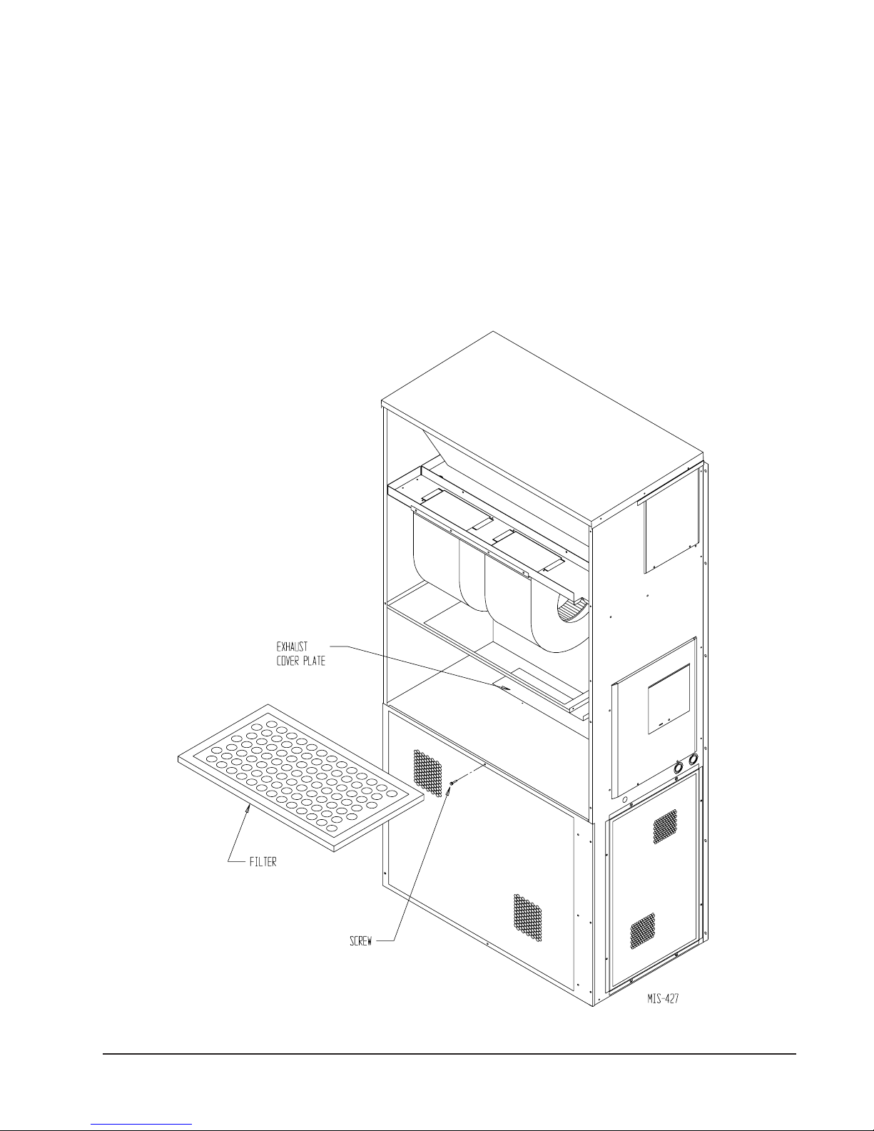
3. Remove and save existing unit air filter and screws
from front center grille. (See Figure 2.)
REMOVAL OF AIR FILTER AND EXHAUST COVER PLATE
4. Remove and discard the exhaust cover plate.
FIGURE 2
Manual 2100-458C
Page 5 of 17
Page 6
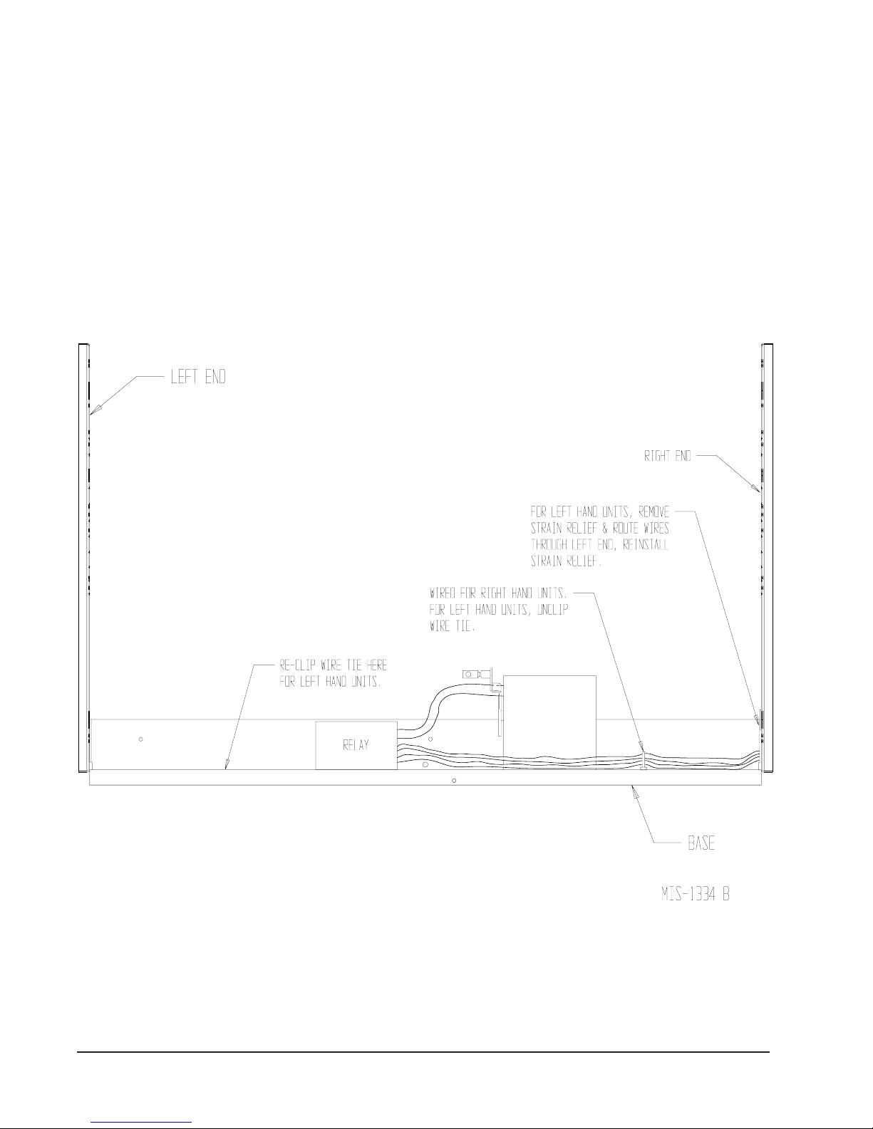
5. For Installation of Left Hand Units Only – Remove
strain relief in right side of CRV. Unclip the (2)
wire ties holding the wire harness. Reroute wires to
left side of CRV. Reinstall wire ties in left side
holes. Route wires through left side and reinstall
strain relief. (See Figure 3.)
REROUTE WIRES FOR LEFT HAND UNITS ONLY
6. Install ventilator by inserting the ventilator into the
unit to the far left side clearing the right filter
bracket. Once the ventilator is fully inserted, slide
the ventilator to the right until it is tight against the
back of the control panel. (See Figure 4.)
FIGURE 3
Manual 2100-458C
Page 6 of 17
Page 7

IMPORTANT: Position front lip of ventilator on
top of front grille and condenser partition. (See
Figure 4 inset.) This is important to ensure proper
drainage of any water entering damper assembly.
INSTALL VENTILATOR
7. Open control panel to gain access to unit low
voltage terminal block.
8. Route electrical harness leads through the 7/8"
bushing in control panel (Figure 4) into low voltage
box.
FIGURE 4
FIGURE 4 INSET
SIDE SECTION
Manual 2100-458C
Page 7 of 17
Page 8

FIGURE 5
CRVS
CRVS LEAD CONNECTIONS
T
X
DM
D
1
3
BK
6
9
B
BR/W
O
BR/W
4
7
CR
A
BK
COMPONENT CODE
CONTROL RELAY
CR
DM
DAMPER MOTOR
TERMINAL STRIP
TBL
COLOR CODE
BLACK
BROWN
RED
ORANGE
YELLOW
GREEN
BLUE
WHITE
BK
BR
R
O
Y
G
BL
W
CRVP
CRVP LEAD CONNECTIONS
DM
COM
CCW
CW
Y
BL
1
3
BK
6
9
B
BR/W
R
O
BR/W
4
7
CR
A
BK
COMPONENT CODE
CR
CONTROL RELAY
DAMPER MOTOR
DM
TERMINAL STRIP
TBL
COLOR CODE
BLACK
BROWN
RED
ORANGE
YELLOW
GREEN
BLUE
WHITE
BK
BR
R
O
Y
G
BL
W
4056-189
9. Connect leads with fork terminal to corresponding
points on unit terminal strip. (See wiring diagram,
Figure 5A or 5B, or on ventilator.)
10. Close control panel cover.
11. Replace left filter support, filter and four (4) screws
in condenser grille.
12. Reinstall the blower access panel at top of unit and
secure with sheet metal screws.
13. Ventilator Checkout
A. Remove mist eliminator to allow access to
minimum position thumbwheel or blade stops.
B. Resupply power to unit.
C. Energize the evaporator blower by switching
thermostat to the manual fan position with
heat/cool in OFF position.
4056-180 A
D. Ventilator should open to the position set by
position adjustment thumbwheel on the CRVS,
or to the blade stops on the CRVP. On the
CRVS, cycle position adjustment thumbwheel
to full open through full close. Observe damper
blade operation throughout travel to assure free,
unobstructed movement. (See Figure 5.)
E. De-energize evaporator blower. Damper blade
should close.
G. This completes ventilator checkout.
14. Adjust damper blade for required ventilation
airflow. (See next section.)
15. Replace mist eliminator. Be sure it is installed with
the drain holes to the bottom.
16. Remove blank off plate or barometric fresh air
damper installed on service access door. Plug four
(4) mounting holes with the plastic plugs provided
with the ventilator.
17. Replace service access panel.
18. Ventilator is now ready for operation.
Manual 2100-458C
Page 8 of 17
Page 9

C RC R G Y W
2
FIGURE 5A
LOW VOLTAGE WIRING AC
8403-057
TH3110D1040
4
C RC R G Y W W2 Y2
2
4
C R G Y1 W1 W2 Y2
C R G Y W1 W2 E F 1 2 3
O
R
BK
3
WIRE OPTIONAL IF BATTERIES ARE USED IN THE THERMOSTAT.
4
WIRE USED ON CRVP ONLY
3
2
FACTORY INSTALLED JUMPER
REMOVE JUMPER IF THERMOSTAT HAS A1 TERMINAL (OCCUPIED) THIS WILL ALLOW THE BLOWER TO RUN
1
WHEN THE CRV IS RUNNING IN OCCUPIED CONDITIONS.
CRVS
CRVP
1
8403-058
TH5220D1151
W3/A1
BR/W
8403-049
1 F93-380
FIGURE 5B
LOW VOLTAGE WIRING HP
UNIT 24V
TERMINAL BLOCK
MIS-2174 A
8403-049
1F93-380
R
RC
9403-058
TH5220D1151
4
Unit 24V
Terminal
WIRE OPTIONAL IF BATTERIES ARE USED IN THE THERMOSTAT.
4
WIRE USED ON CRVP ONLY
3
2
FACTORY INSTALLED JUMPER
REMOVE JUMPER IF THERMOSTAT HAS A1 TERMINAL (OCCUPIED) THIS WILL ALLOW THE BLOWER TO RUN
1
WHEN THE CRV IS RUNNING IN OCCUPIED CONDITIONS.
Block
R
3
Y1R
G
C
C
C
Y2
G
Y
G
Y
O
BK
RED
W3
E
W2
W1
AUX
O/B
W1
Y1
2
CRVS
CRVP
L
A1
E
L
B
W2
W3
2
B
O
L
DH
E
1
BR/W
E2
P
01
MIS-2186 A
Manual 2100-458C
Page 9 of 17
Page 10

FIGURE 6
CRVS POSITION ADJUSTMENT
NOTE: POSITION ADJUSTMENT
THUMBWHEEL IS LOCATED
ON BACK OF MOTOR ABOVE
THE WIRING TERMINALS
CLASSROOOM VENTILATOR MOTOR
ADJUST FULL OPEN
POSITION WITH THUMBWHEEL
ROTATE UP TO OPEN
DOWN TO CLOSE
BLADE ADJUSTMENT FOR DESIRED
VENTILATOR AIR
The amount of ventilation air supplied by the
commercial room ventilator is dependent on five (5)
factors.
1. Return air duct static pressure drop.
2. Supply air duct static pressure drop.
3. Indoor blower motor speed.
4. Damper blade open position setting.
5. Tightness or looseness of building envelope.
POSITION
ADJUSTMENT
THUMBWHEEL
Determine on what speed the evaporator motor is
running.
Refer to the graphs on the following pages to determine
the blade setting necessary to achieve the ventilation air
required. With the blower energized, use the
thumbwheel on the CRVS-5, adjust blade to desired
blade position. On the CRVP-5, move the blade stops
on the sides of the CRVP to the desired blade position making sure the stops are parallel side to side.
ADJUSTMENT
THUMBWHEEL
BACK OF
ACTUATOR
MOTOR
MIS-2188
Manual 2100-458C
Page 10 of 17
Page 11

1700
1600
1500
1400
1300
1200
1100
1000
900
800
Airflow (cfm)
700
600
500
400
300
200
100
0
SH381 HIGH SPEED TOTAL AND VENTILATION AIRFLOW
Total Air 0 ESP
Total Air .2 ESP
Vent Air 0 ESP
Vent Air .2 ESP
ABCDEF
Vent Position
1600
1500
1400
1300
1200
1100
1000
900
800
700
Airflow (cfm)
600
500
400
300
200
100
0
SH381 MEDIUM SPEED TOTAL AND VENTILATION AIRFLOW
Total Air 0 ESP
Total Air .2 ESP
Vent Air 0 ESP
Vent Air .2 ESP
ABCDEF
Vent Position
Manual 2100-458C
Page 11 of 17
Page 12

1300
1200
1100
1000
900
800
700
600
Airflow (cfm)
500
400
300
200
100
0
SH381 LOW SPEED TOTAL AND VENTILATION AIRFLOW
Total Air 0 ESP
Total Air .2 ESP
Vent Air 0 ESP
Vent Air .2 ESP
ABCDEF
Vent Position
1800
1700
1600
1500
1400
1300
1200
1100
1000
900
800
Airflow (cfm)
700
600
500
400
300
200
100
0
SH431/SH491/SH611 HIGH SPEED TOTAL AND VENTILATION AIRFLOW
Total Air 0 ESP
Total Air .2 ESP
Vent Air 0 ESP
Vent Air .2 ESP
ABCDEF
Vent Position
Manual 2100-458C
Page 12 of 17
Page 13

1600
1500
1400
1300
1200
1100
1000
900
800
700
Airflow (cfm)
600
500
400
300
200
100
0
SH431/SH491/SH611 MEDIUM SPEED TOTAL AND VENTILATION AIRFLOW
Total Air 0 ESP
Total Air .2 ESP
Vent Air 0 ESP
Vent Air .2 ESP
ABCDEF
Vent Position
2100
2000
1900
1800
1700
1600
1500
1400
1300
1200
1100
1000
900
Airflow (cfm)
800
700
600
500
400
300
200
100
0
WA/WH42 & WA/WH48 HIGH SPEED TOTAL AND VENTILATION AIRFLOW
Total Air 0 ESP
Total Air .2 ESP
Total Air .4 ESP
Vent Air 0 ESP
Vent Air .2 ESP
Vent Air .4 ESP
ABCDEF
Vent Position
Manual 2100-458C
Page 13 of 17
Page 14

1700
1600
1500
1400
1300
1200
1100
1000
900
800
Airflow (cfm)
700
600
500
400
300
200
100
0
WA/WH42 & WA/WH48 LOW SPEED TOTAL AND VENTILATION AIRFLOW
Total Air 0 ESP
Total Air .2 ESP
Total Air .4 ESP
Vent Air 0 ESP
Vent Air .2 ESP
Vent Air .4 ESP
ABCDEF
Vent Position
2200
2100
2000
1900
1800
1700
1600
1500
1400
1300
1200
1100
1000
Airflow (cfm)
900
800
700
600
500
400
300
200
100
0
WA/WH60 HIGH SPEED TOTAL AND VENTILATION AIRFLOW
Total Air 0 ESP
Total Air .2 ESP
Total Air .4 ESP
Vent Air 0 ESP
Vent Air .2 ESP
Vent Air .4 ESP
ABCDEF
Vent Position
Manual 2100-458C
Page 14 of 17
Page 15

1600
1500
1400
1300
1200
1100
1000
900
800
700
Airflow (cfm)
600
500
400
300
200
100
0
WA/WH60 LOW SPEED TOTAL AND VENTILATION AIRFLOW
Tot al A ir 0 ESP
Total Air .2 ESP
Total Air .4 ESP
Vent A ir 0 ESP
Vent A ir .2 ESP
Vent A ir .4 ESP
ABCDEF
Vent Position
Manual 2100-458C
Page 15 of 17
Page 16

COMMERCIAL ROOM VENTILATOR –
WA, WH AND WL SERIES
FEATURES
•
One piece construction – easy to install with no
mechanical linkage adjustment required.
•
Exhaust air damper – built in with positive closed
position. Provides exhaust air capability to prevent
pressurization of tight buildings.
CALL FOR BLOWER OPERATION
•
•
COMMERCIAL ROOM VENTILATOR
SEQUENCE OF OPERATION
On a call for blower operation, CRV opens to a
position as set by minimum position potentiometer. See
Figure 7.
FIGURE 7
Actuator motor – 24 volt, power open, spring return
with built in torque limiting switch.
Provides up to 75 percent of outside air.
Manual 2100-458C
Page 16 of 17
Page 17

A call for cooling cycles the compressor, and dampers
remain in the ventilation mode. On loss of blower
operation, CRV closes fully. See Figure 8.
CALL FOR COOLING OPERATION
FIGURE 8
Manual 2100-458C
Page 17 of 17
 Loading...