

Page 1

USER’S GUIDE
Please read this manual before using this projector
RLM W12
User’s Guide
Page 2

RLM
W12
INDEX
Warning, Notices and Safety Instructions 4
Notice 4
Description pertaining to FCC Rules Part 15e: 4
Warning and Safety Instructions 5
Notices you should read prior to the installation of the projector 7
Projector parts and functions 10
Front view 10
Rear view 10
Bottom view 12
Range of effective remote control signal reception 13
Installing batteries in the remote control 13
Quick installation of the projector 14
Throw distance 17
Modes of installation 17
Horizontal and vertical lens shift 19
Installing the projector 20
Connecting the projector to other devices 20
12V Trigger connection 20
RGB connection 21
RGBs connection 22
IR INPUT connection 22
S-Video/Video connection 23
COMPONENT connection 23
Turning on the projector 24
Changing OSD language 24
Adjusting screen orientation 25
Adjusting the projector lens 26
2
Page 3

Using the remote control 28
OSD Menu Tree 30
OSD Menu Description 32
INPUT 32
IMAGE 34
LAYOUT 39
LAMP 43
ALIGNMENT 45
CONTROL 51
SERVICE 54
RLM
W12
Lamp and filter maintenance 55
Lamp replacement 55
Cleaning the fi lter 56
Simple troubleshooting and definition of the
LED indicators 58
Projector specifications 60
SDI formats 62
3
Page 4

RLM
W12
Warning, Notices and Safety Instructions
Notice
Please write down your projector model number and serial number and keep the information
for maintenance purposes in the future. Should the equipment be lost or stolen, the
information could also be used for the police report.
Model number:
Serial number:
Please check the accessories that come with the projector with the following list. Should you
fi nd any missing accessory, contact your dealer immediately.
1: US specifi cation power cord*1
2: EU specifi cation power cord*1
3: China specifi cation power cord*1
4: Remote control *1
5: AA battery *2
6: CD User Manual *1
7: Quick Start Guide *1
8: WEEE Notifi cation Card *1
Description pertaining to FCC Rules Part 15e:
This device has been tested and found to comply with the limits for a Class A digital device,
pursuant to Part 15 of the FCC Rules.These limits are designed to provide reasonable
protection against harmful interference in a residential installation.
This equipment generates, uses and can radiate radio frequency energy.If not installed
and used in accordance with the instructions, may cause harmful interference to radio
or television reception.However, there is no guarantee that interference will not occur in
a particular installation.If this equipment does cause interference to radio or television
reception, which can be determined by turning the equipment off and on, the user is
encouraged to try to correct the interference by one or the following measures:
Reorient or relocate the receiving antenna.
•
Increase the separation between the equipment and receiver.
•
Connect the equipment in to an outlet on a circuit different from that to which the receiver
•
is connected.
Consult the dealer or an experienced radio/TV technician for help.
•
This Class A digital apparatus meets all requirements of the Canadian ICES-003 Standards.
Cet appareil numérique de la classe A est conforme à la norme NMB-003 du Canada.
The lamp(s) in this product contain mercury.This product could contain other electronic
wastes that might be hazardous if not handled properly.Please consult your local/state/
federal regulations regarding disposal or recycling.
4
Page 5
Warning, Notices and Safety Instructions
For more information, please contact Electronic Industries Alliance (WWW.EIAE.
Hg
ORG).
For information on proper lamp handling, visit WWW.LAMPRECYCLE.ORG.
Warning and Safety Instructions
Special Care for Laser Beams!
Special care should be considered when DLP projectors and high power laser equipment are
used in the same room as.
Direct or indirect hit of a laser beam on to the projector lens can severely damage the Digital
Mirror Devices (DMD™).
Sun light Warning
Avoid using the RLM W12 in direct sun light.
Sun light on the projector lens can severely damage the Digital Mirror Devices (DMD™).
Never look into the projector light source directly
RLM
W12
This equipment contains a high brightness light source and a portion
of the light emitted by the projector is ultraviolet light. Never look into
the projector light source directly and pay special attention to prevent
AVOID EYE CONTACT TO THE LIGHT
children from looking into the projector light source as it can damage
their eyes.
CAUTION
RISK OF ELECTRIC SHOCK
DO NOT OPEN
CAUTION / TO REDUCE THE RISK OF ELECTRIC SHOCK
DO NOT REMOVE COVER(OR BACK)
NO USER-SERVICEABLE PARTS INSIDE
REFER SERVICING TO QUALIFIED SERVICE PERSONNEL
The lightning flash with an arrowhead within a triangle
is intended to tell the user that inside this product
may cause risk of electrical shock to persons.
The exclamation point within a triangle is intended to tell
the user that important operating and/or servicing instructions
are included in the technical documentation for this equipment.
Do not turn off the projector by unplugging the power cord.
Under normal operations, be sure to use the SOFT POWER button to turn off the projector.
And as such, avoid shutting off AC power to turn off the projector since it could lead to lamp
malfunctioning or damage.
Electric shock
To protect your projector, avoid turning on the projector during lightning storms and unplug it
from the wall outlet. This will prevent sudden electrical surges caused by the lightning from
damaging the projector.
Do not overload wall outlets/extension cords
Pay attention to the current load of the outlet you are using, be it wall outlet or extension cord
outlet to prevent fi re or electric shock.
5
Page 6

RLM
W12
Warning, Notices and Safety Instructions
Cleaning
When cleaning the projector, be sure to unplug it from the wall outlet to prevent electric
shock.
Do not use liquid or aerosol cleaners. Use a dry/damp cloth with excessive moisture removed
for cleaning. Be sure to use cleaning cloth designed to clean monitors for the projector to
prevent damages to the projector casing due to abrasion.
Dampness, smoke, steam, dust, high temperature and direct
exposure to sunlight
Do not operate the projector in environments where it could be expose to dampness, smoke,
steam, dust, high temperature or direct sunlight.For example: bathroom, kitchen, adjacent to
washing machine, damp basement rooms, electric heaters or similar environments.Keeping
or operating the projector in the above-mentioned environment could lead to discoloration,
mold formation, grease or damages to the projector.
Ventilation
The projector case is designed with slots and openings to remove the heat inside the
projector so that it will not overheat and damage the components.Be sure to operate the
projector in an environment with ideal ventilation and don't operate it on a sofa, rug or other
closed-in environments that could obstruct ventilation.
Filter
Make sure to clean or replace the fi lter when it is required to keep the air intake clear of dust,
and prevent possible over temperature issue of the projector due to the clog of fi lter. Please
refer to Page 55 for details of fi lter replacement procedure.
Intrusion of foreign objects
Be sure to keep all foreign objects away from entering the projector because it could be
exposed to hazardous voltages and cause parts to short circuit. This could in turn lead to fi re
hazard or electric shock.Examples of foreign objects include: cockroach, screws, liquid and
so forth.
In addition, never spill liquid into the projector.
Carrying the projector
When moving the projector on a cart, be sure to handle the cart with care
as abrupt stops, jolts of excessive force or uneven ground could lead the projector
to topple.
Please install the projector on an even and stable surface
Avoid placing the projector on unstable cart, tripod, table and so forth to prevent the projector
from falling, becoming damaged or causing injuries.
Servicing
Should you encounter problem with the projector, please seek assistance from your local
dealer or qualifi ed service personnel. Do not attempt to service the projector yourself so that
you would not be exposed to high voltage or other potential hazards.
6
Page 7

Warning, Notices and Safety Instructions
Should you encounter any of the following situation, please unplug your projector from the
wall outlet and contact a qualifi ed service personnel for assistance:
Damaged power cord or power plug.
•
If a foreign object has fallen into the projector or if you have spilled water or other liquid
•
into the projector.
If the projector has been dropped accidentally or damaged.
•
If you experience noticeably poor performance or malfunctioning with the projector despite
•
having followed instructions for normal operation
.
Changing parts
Should any part of the projector be damaged, check with your servicing personnel that only
manufacturer certifi ed parts were used for replacement. Used of non-certifi ed parts may
result in damages to the projector or hazards such as fi re or electric shock.After changing
parts, be sure to remind the servicing personnel to perform safety inspections to ensure that
the projector operates normally.
Power cord
Don't place the projector where the cord can be walked on. This may result in fraying or
damage to the power cord, especially at the plug and the point of connection between the
power cord and the projector.
Please use the power cord that comes with the projector or the type of power cord specifi ed
for the projector (refer to the descriptions printed on the power cord). If you are not sure of
the power available at the region you are in, consult your local power company to prevent
damages to the projector due to the use of wrong power cord or potential fi re hazards due to
current overload.
Depending on the country and region you are in, the voltage and type of socket of the wall
outlet may be different from the projector. If you are unable to fi t the power plug into the wall
outlet, contact your local dealer and do not remove the extra pin on the power plug to forcibly
fi t it to the socket at the risk of your own safety.
RLM
W12
Notices you should read prior to the
installation of the projector
Safety issues related to the lamp
The lamp used in this projector contains mercury. Should the lamp be broken, please be
careful when handling the glass shards and keep the surrounding environment well ventilated.
Be sure to wear a mask that offers adequate protection before cleaning up to prevent inhaling
mercury vapor that could cause bodily harm.For instructions on lamp replacement, refer to "
Page 55 : Lamp replacement ".
Take frequent breaks to let your eyes rest
Prolonged viewing of the projector screen could strain your eyes. Please be sure to rest your
eyes adequately.
Installation environment for the projector
You should avoid installing the projector at place of excessive dampness, dust or smoke. If
installation in such environment is unavoidable, be sure to have the interior of the projector
7
Page 8
RLM
W12
Warning, Notices and Safety Instructions
cleaned routinely to prolong the projector's lifecycle. Cleaning of the projector's interior should
only be performed by qualifi ed service personnel dispatched by your local dealer and you
should not attempt to clean the inside of the projector by yourself.
If other light source is directly projected onto the projector screen, the color of the image from
the projector will appear to be pale and the image quality will be lower. In addition, your eyes
would be more prone to fatigue. Therefore, it is recommended that the projector be installed
in places without direct exposure to sunlight or other sources of intense light.
The ideal operating temperature range for the projector is between 32°F ~ 104°F (0°C ~ 40°C)
The ideal storage temperature range for the projector is between -4°F ~ 104°F (0ºC ~ 40°C)
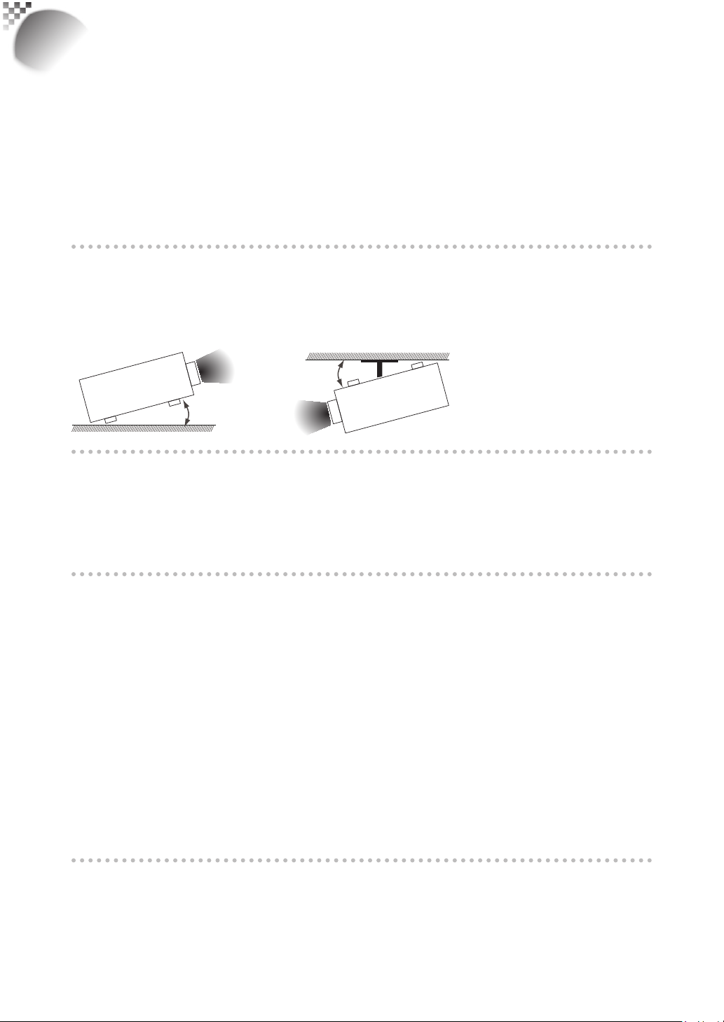
Do not tilt the projector more than 15 degrees.
The maximum tilt angle for the projector is 15 degrees.
When the projector is tilted more than 15 degrees, it will shorten the life of the projector lamp
and may lead to other unpredictable damages.
Can’t >15°
Can’t >15°
Confi gurations for projector operation at high altitudes
When operating the projector at higher altitudes, be sure to manually set the fan mode to "High"
or it could shorten the life of the optical system in the projector.High altitude is defi ned as
places being 1500 meters (4900 feet) or higher.
Please refer to " Page 44 : High Altitude Mode ".
Keep the projector's ventilation inlets and outlets free from obstructions
Be sure to keep objects for no less than 30cm away from the ventilation inlets and outlets of the
projector and note the direction of air fl ow at the designated spot of installation. Do not let the
hot air released from the outlet fl ow back to the inlet as it will prevent proper cooling and lead to
damage of the projector's internal structure.
In the event of high temperature due to malfunctioning of the internal cooling fan caused by
clogging at the ventilation inlets and outlets, the projector will activate its automatic protection
mode and shutdown. When this happens, it does not necessary mean that the equipment is
malfunctioning. Try to unplug the power cord from the wall outlet and wait for approximately 15
minutes before operating the projector again (remember to remove the objects that have caused
poor ventilation so that the projector will not go into the protection mode again). Please refer to "
Page 58 : LED STATUS ".
Description: The regulation of temperature inside the projector by the cooling fan is automatic. And
as such, the sound of cooling fan changing its operating speed does not imply that a problem has
occurred with the projector.
Protect the projector with care
When placing the projector at a high position, be sure to secure the projector fi rmly so that
it would not fall and cause injuries.Take care to protect the projector's lens from collision,
abrasion or other damages.Be sure to close the lens cover or cover the projector with a dust
cover if you need to store the projector or if it will not be used for an extended time.
8
Page 9
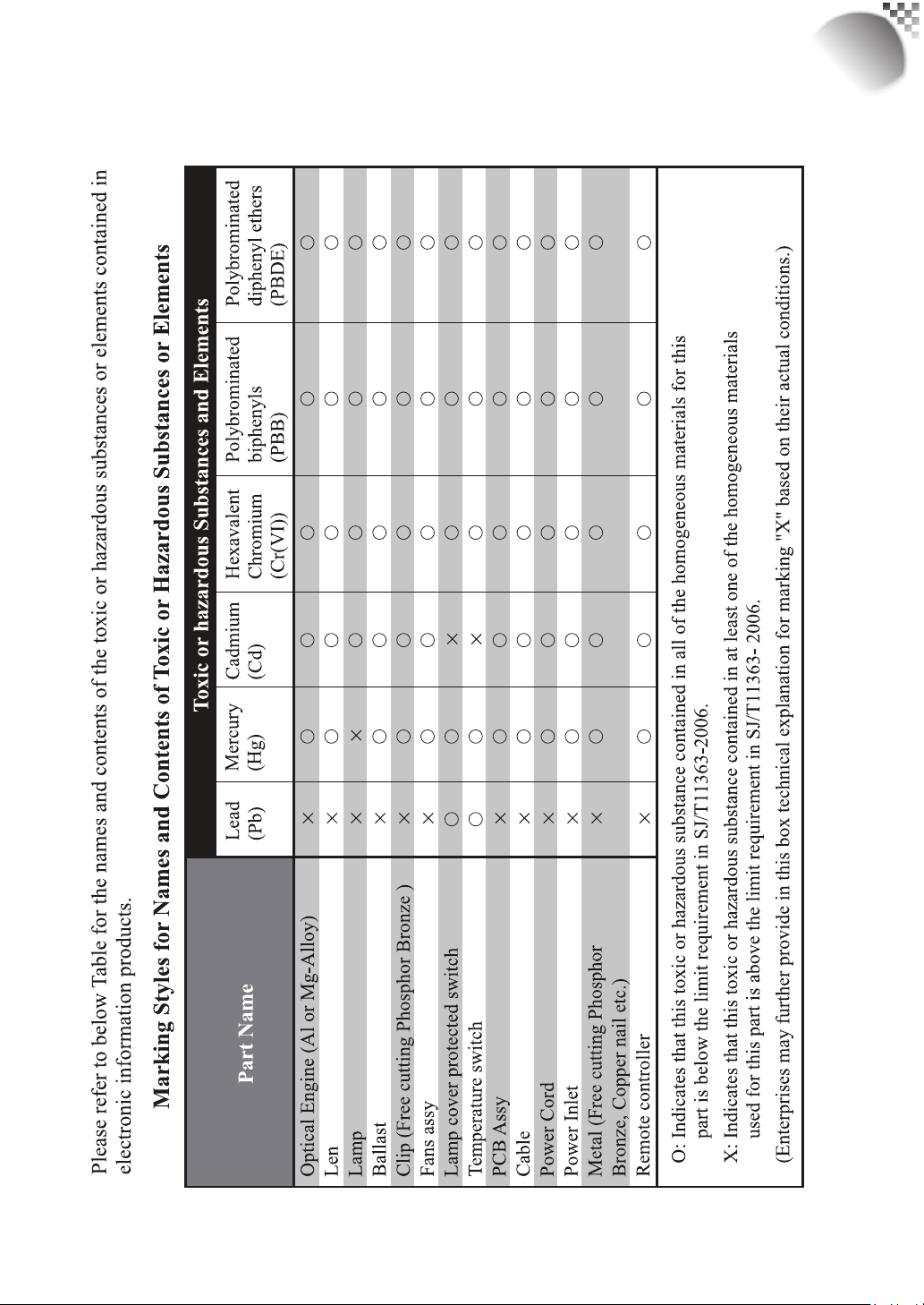
Warning, Notices and Safety Instructions
Name and quantity of toxic/hazardous substances/elements
contained in the product
RLM
W12
9
Page 10
RLM
W12
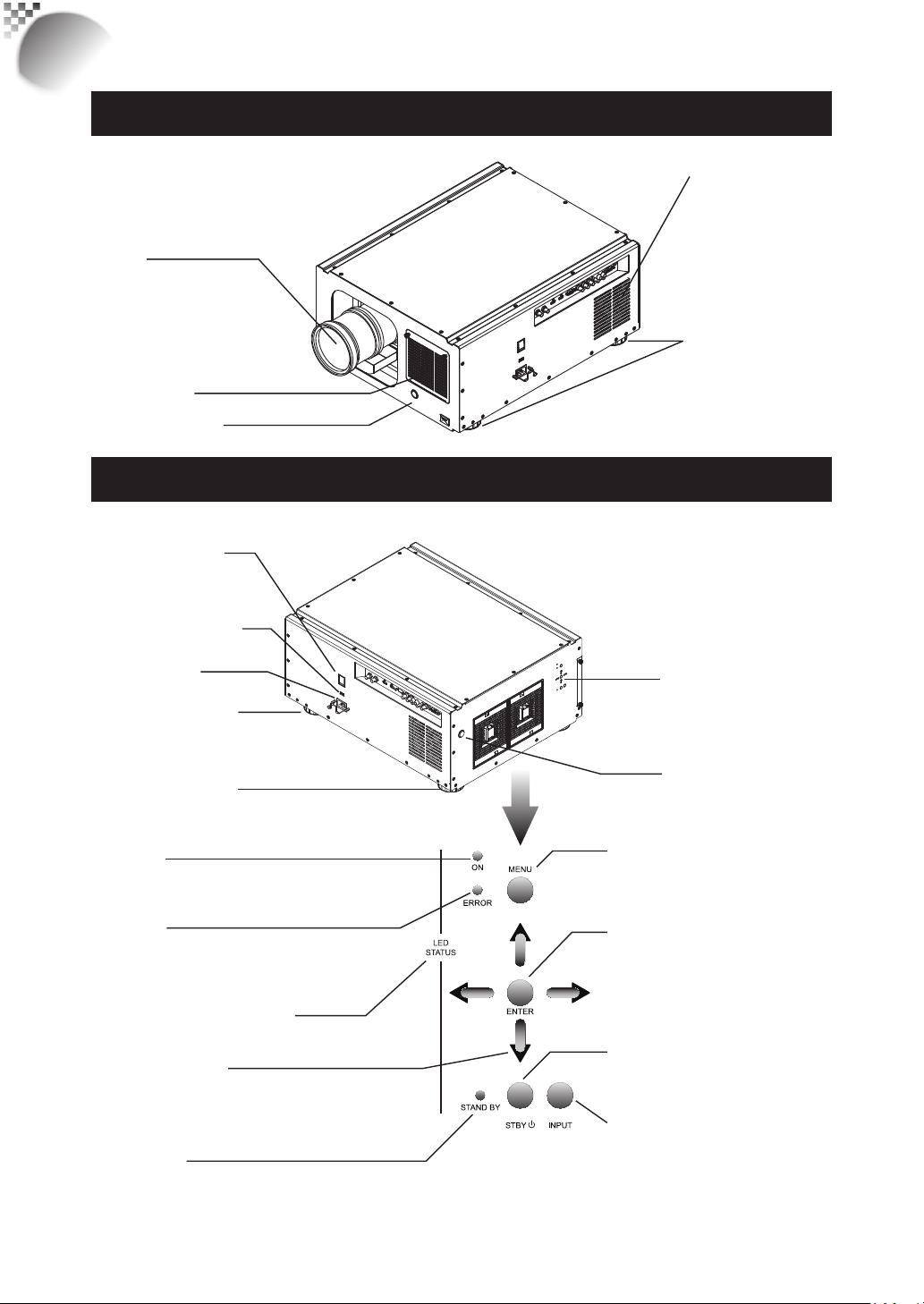
Projector parts and functions
Front view
Lens
Ventilation slot
The hot air generated
inside the projector is
dispersed through the
ventilation slot. Make
sure the ventilation slot
is free from obstruction.
Ventilation inlet
The internal cooling fan draws
cool air from the ventilation inlet
into the projector.
Infrared receiver
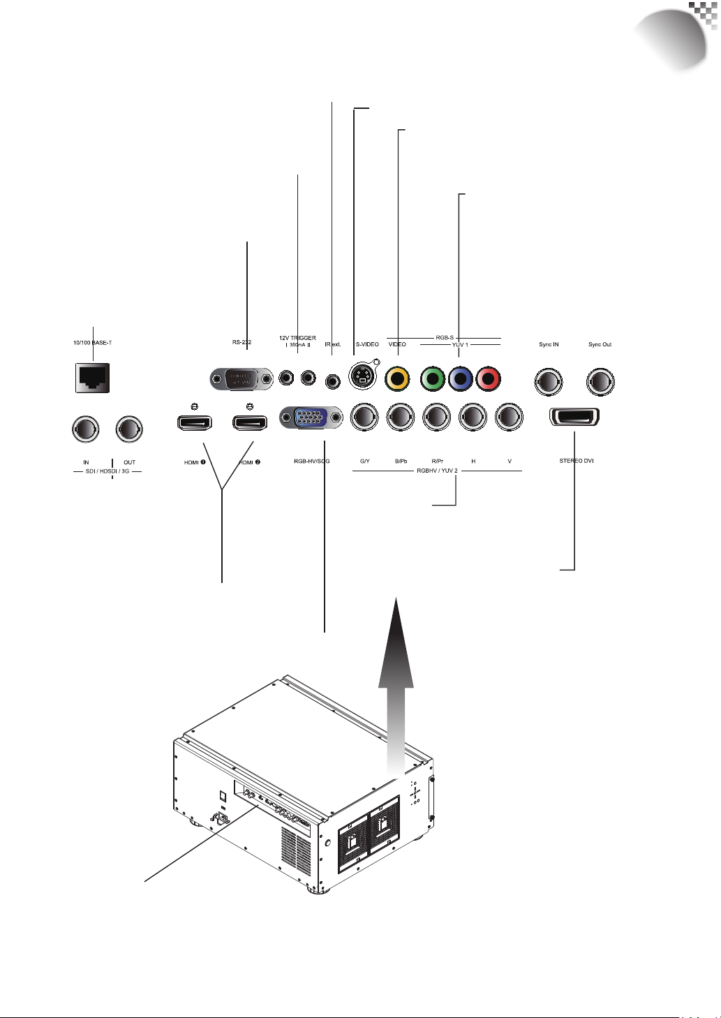
Rear view
Power switch
I → ON
O → OFF
Voltage Selector
(Default at 110V)
Power inlet
Adjustable foot
Adjustable foot
POWER
Displays the projector's power
status
ERROR
Displays the cause of problem (i.e.
temperature, fan, lamp or system)
that has led to projector malfuncti
on.
Refer to " Page 58 : LED STATUS ".
fot the detail display information.
▲▼
Use these buttons to scroll,
confi gure or adjust items on the
OSD or toggle between different
images.
STAND BY
The indic ator that shows the projector's
standby status
bottons
▼
▲
.
Adjustable foot
Adjust the height and angle of the
projector with the adjustable foot
Projector Keypad
Infrared sensor
MENU
Displays or hides the OSD
adjustment screen
ENTER
Press this button to confi rm selection
of OSD item; you can choose from
"Select Item" or access "Sub Menu"
confi gurations.
STBY
Use this button to star t up or shut down
the projector
.
INPUT
Used to toggle between different input
signal source
Refer to “ Page 32 : Input Selection “. for
more details
10
Page 11
Projector parts and functions
RLM
W12
IR ext.
Receives input signal from compatible Niles or Xantech IR
repeater systems.
12V TRIGGER
(3.5- mm, mini phone jack)
Offers 12 (+/- 1.5) V of output for 350mA monitor relay
with short circuit protection.
RS-232
9-pin D-sub socket. Connects your PC or
automatic home theater /control system.
10/100 BASE-T
Connects the projector to your
PC via network to enable direct control of the projector on
your PC.
S-VIDEO
Standard S-Video input that connects to DVD players, satellite
receiver or Super VHS (S -VHS) VCR.
VIDEO
Connects to VCR, laser disc players or other
component image sources.Also connects to the
composite image synchronized input from RGBS input
source.
YUV1
Standard and high defi nition (480i/480p/
576i/576p/720p/1080i/1080p) component
input, connects to DVD/HD-DVD/BD player,
HD set-top-box or other SD/HD input source.
Also connects to RGB input from RGBS input
source.
SDI/HDSDI/3G
IN/OUT
Serial digital inter face, use
BNCconnects input or output
the image.
HDMI 1 & 2
HDCP compatible digital image input;
connec ts to sources using HDMI or DVI.
RGBHV/SOG
Standard 15-pin VGA connection socket to connect to RGB,
high- defi nition c omponent input or PC.The projector will
automatically detect the resolution of the input signal.
IO Control
(Input/Input control panel)
RGBHV/YUV2
Connects to the fi ve BNC inputs for
component (YPbPr) image source and
channel (Hs, Vs) source.
STEREO DVI
Use this DVI dual link to connect to a stereo
3D source – it is usually a computer with 3D
Graphics card, and 3D applications.
3D Sync In
The 3D Sync In signal is generated from the
3D source to make sure the left/right eye
content is synchronized to the user and the
projector.
3D Sync Out
It is typically used to connect to the IR
emitter that sends L/R signals to the receiver
in a 3D shutter glass that c ontrols L/R
shutters alternatively to open or close for 3D
applications.
11
Page 12
RLM
W12
Projector parts and functions
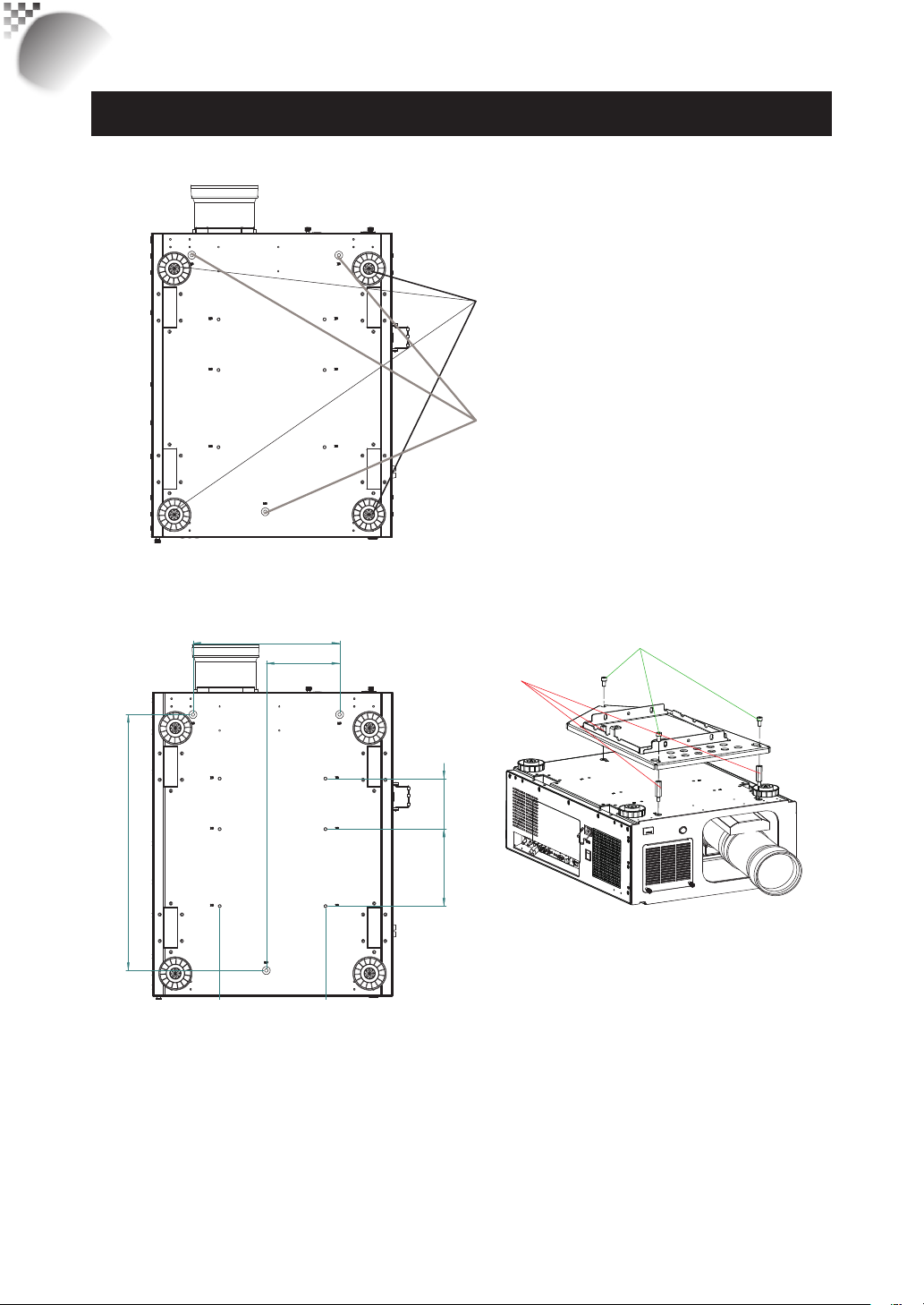
Bottom view
Adjustable foot
Adjust the height and angle of the projector
with the adjustable foot
Mounting bracket screw hole
These screw holes are used to mount the projector
to its designated mounting bracket using 3 M8x15
screws and 3 M8x40 bolts. The dimensions of the
screw holes are shown in the image below.
305
152.5
532
Ceiling Mount Order Info:
1. R9849999-Ceiling mount
2. R9841260-Short Pulley 400mm to 765mm
3. R9841261-Long Pulley 800mm to 1165mm
M8x15
3 screws
M8x40
3 bolts
105
160
12
Page 13
Projector parts and functions
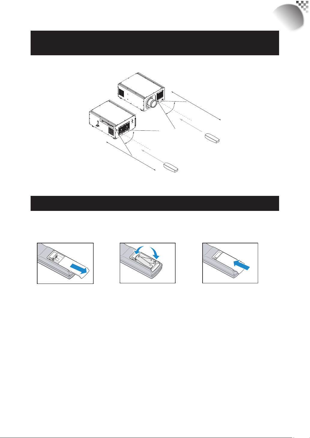
Range of effective remote control signal
reception
The diagram below illustrates the range of effective remote control signal reception.
12m
40°
40°
12m
RLM
W12
Note: Avoid placing the remote control at places of high temperature or humidity as it could cause the
remote control to malfunction.
Installing batteries in the remote control
Remove the cover by
sliding it in the direction
indicated by the arrow.
Note1: Be sure to insert the batteries in the corresponding orientations to match the polarities.
Note2: Do not mix new batteries with used batteries as it would shorten the life of new batteries or cause
leakage.
Note3: Only used AA batteries as instructed; do not attempt to insert different types of batteries into the remote
control.
Note4: If the remote is going to be unused for long periods of time, be sure to remove the batteries to prevent
leakage, which could damage the remote control.
Note5: The liquid contents in the batteries is harmful to the skin; do not touch the leakage with your bare hands
directly. When installing fresh batteries, be sure to clean up the leakage thoroughly.
Note6: Under most circumstances, you only need to point the remote control towards the screen and the IR
signal would be refl ected off the screen and picked up by the IR sensor on the projector.But under specifi c
circumstances, the projector may fail to receive signals from the remote control due to environmental
factors.When this happens, orient the remote control at the projector and try again.
Note7: If the range of effective remote control signal reception decreases or if the remote control stops working,
replace the batteries.
Note8: If the infrared receiver is exposed to fl uorescent lamp or strong sunlight, the remote control may not
operate normally.
Note9: Refer to the regulations enforced by your local government on the disposal of used batteries; improper
disposal could damage the environment.
Insert two new AA
batteries
(observe the polarity).
Replace the cover.
13
Page 14
RLM
RGB-S
RGBHV / YUV 2
W12
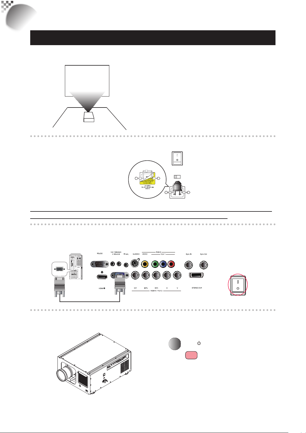
Quick installation of the projector
Quick installation of the projector.
1. Orient the projector towards the screen
Screen
2. Connect the power cord to the projector
Please select the
correct input voltage
before removing the
AC POWER SWITCH
VOLTAGE SELECT
warnning labe.
AC MAINS
100-130 / 200-240 Volts
50/60Hz
Please note that select the correct input (110V or 220V) voltage according to the area
where you operate the projector before you turn on the power switch.
3. Connect the projector to your PC and fl ip the switch to “I” to
turn on the power.
Desk Top or Notebook
桌上型或是筆記型電腦
4. Remove the lens PU foam on the projector before starting it up.
AC POWER SWITCH
14
Press the
projector or the
STBY
button on the
l
button on the
remote control to start up the projector.
Page 15
Quick installation of the projector
5. Adjusting the projector's angle
a. Please use the adjustable feet to change the angle of the projector in order to achieve
the most suitable angle for projection on the screen.
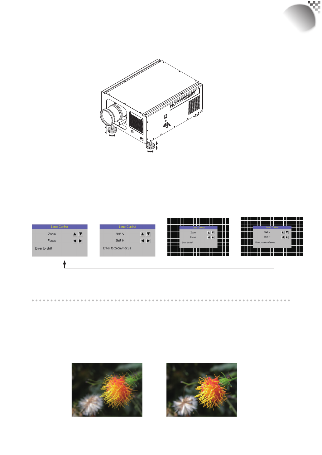
b. Adjusting the lens by horizontal and vertical lens shift
Method 1: Press the ENTER button on the remote control to access Lens Control
adjustment screen before pressing ENTER once again to access the menu
Press ENTER once to
adjust zoom and focus
and use the ▼▲
the lens.
Press ENTER again
to adjust vertical and
horizontal lens
buttons to adjust the horizontal or vertical position of
▼
▲
Press ENTER once to
adjust zoom and focus with
cross line
Press ENTER once to
Adjust Lines shift with
cross line
shift
RLM
W12
Enter
Enter
Enter
Enter
Method 2: Press the MENU button on the remote control and choose Alignment
Lens Control; then use the ▼▲
buttons to adjust the
▲ ▼
horizontal or vertical position of the lens.
6.Adjusting focus and zoom.
a. Press the MENU button on the remote control and choose Alignment Lens Control
to activate the Lens Control OSD, press enter to go through “Zoom/Focus”, “Lens
Shift”, “Zoom/Focus with Grid test pattern”, “Lens Shift with Grid test pattern” OSDs
Cyclically. Stop at either “Zoom/Focus” or “Zoom/Focus” with Grid test pattern” OSD
; then use the
buttons to adjust the lens' focus (clarity).
▼
▲
15
Page 16
RLM
W12
Quick installation of the projector
b. Press the MENU button on the remote control and choose Alignment Lens Control
to activate the Lens Control OSD, press enter to go through "Zoom/Focus", "Lens
Shift", "Zoom/Focus with Grid test pattern", "Lens Shift with Grid test pattern" OSDs
Cyclically. Stop at either "Zoom/Focus" or "Zoom/Focus" with Grid test pattern" OSD;
then use the ▼▲ buttons to adjust the size of the image that is projected onto the
screen.
Original image size
Zoom out Zoom in
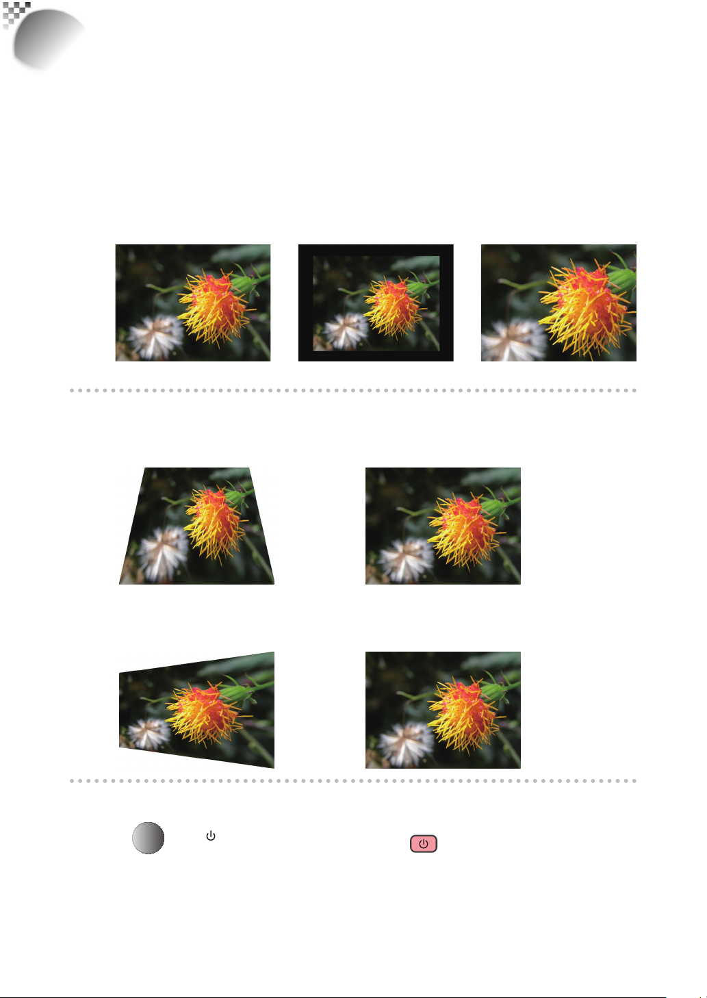
7. Correcting keystoning caused by projection angle
a. To adjust keystoning, press the MENU button on the remote control and choose
ALIGNMENT Warp Keystone and use ▼▲ buttons to adjust Vertical Keystone.
b. To adjust keystoning, press the MENU button on the remote control and choose
ALIGNMENT Warp Keystone and use
buttons to adjust Horizontal Keystone.
▲
▼
8. Turning off the projector
Press the
least 3 seconds to turn off the projector. When the projector has been turned off, the cooling
fan will remain in operation for approximately 90 seconds.
16
STBY
button on the projector or the button on the remote control at
Page 17
Installing the projector
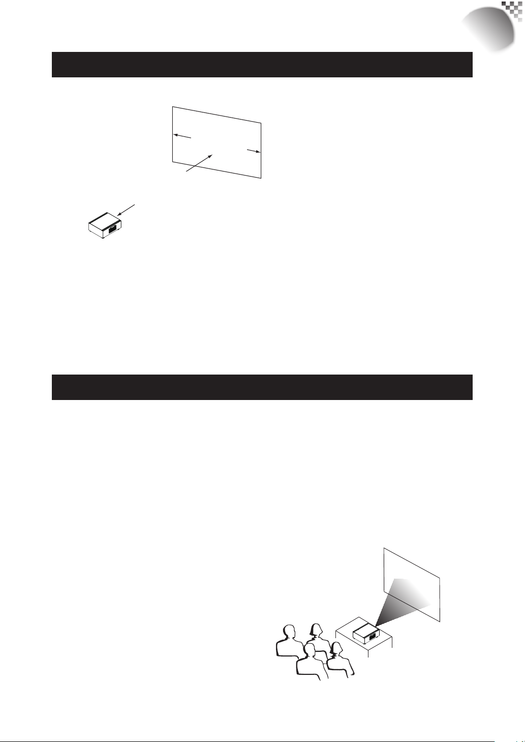
Throw distance
Throw Distance (TD) = Screen Width (W) x Throw Ratio (TR)
Screen Width (W)
Throw Distance (TD)
Coupled with the available projection lenses, the projector offers the following throw ratios:
R9862000-TLD+ (0.73:1)
•
R9840775-TLD+ (1.2:1)
•
R9862010-TLD+ (1.5 - 2.0:1)
•
R9862020-TLD+ (2.0 - 2.8:1)
•
R9862030-TLD+ (2.8 - 4.5:1)
•
R9862040-TLD+ (4.5 - 7:5:1)
•
R9829997-TLD+ (7.5 - 11.2)
•
R9862005-TLD+ Ultra (1.25-1.6)
•
Note:
Projection lenses are optional
accessories. Please contact your
local dealer to acquire the projection
lens that suits your need most.
RLM
W12
Modes of installation
Install the projector in an environment below 35°C (95°F). The projector should be kept
•
clear from sources of heat and / or ventilation openings of air conditioner.
The projector should be kept away from devices that emit electromagnetic energy, such
•
as motor and transformer.Common devices that emit electromagnetic energy include
slideshow system, speakers, power amplifi ers and elevators.
If you choose to install the projector on the ceiling, be sure to use the ceiling installation
•
components manufactured by manufacturer-certifi ed vendors. For details, please contact
your local dealer.
Frontal projection - desktop installaion
Advantages: easy to install can be easily
moved or adjusted easy to
operate.
Disadvantage: occupies fl oor space and limits
seating capacity.
17
Page 18
RLM
Screen
W12
Installing the projector
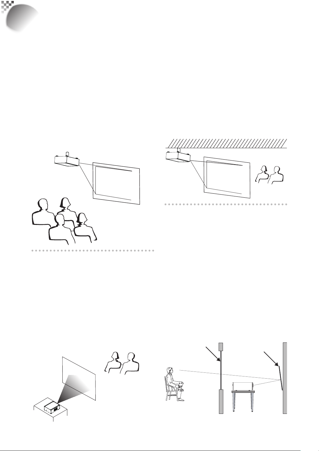
Frontal projection - ceiling mode
Advantage: does not occupy fl oor space
does not draw attention to it.
Eliminates the possibility that
someone would accidentally
move the projector.
Disadvantage: stricter installation
requirements and conditions;
care should be taken during
the installation to ensure
the projector has been
securely mounted.
operation of the projector
becomes inconvenient without
the remote control.
Rear projection - ceiling installation
Advantage: the projector is completely
hidden from plain view this setup
usually offers better reduction of
ambient noise.
Disadvantage: requires an additional room for
installation. Stricter installation
requirements and conditions;
care should be taken during
the installation to ensure the
projector has been securely
mounted. operation of the
projector becomes inconvenient
without the remote control.
Rear projection - desktop
installaion
Advantage: the projector is completely
hidden from plain view
the projector can be easily
operated this setup usually
offers better reduction of ambient
noise.
Disadvantage: requires an additional room
for installation relatively higher
costs for installation.
Rear projection - submersive
installation
If you wish to have a rear projection setup
with limited space to the rear of the projector,
you can use a mirror to refl ect the light
path. However, both the projector and the
mirror have to be precisely located.If you are
considering such installation, please contact
your dealer for assistance.
Advantage: the projector is completely
hidden from plain view
this setup usually offers better
reduction of ambient noise.
Disadvantage: requires an additional room
for installation relatively higher
costs for installation.
Mirror
18
Page 19
Range of vertical
Range of
Installing the projector
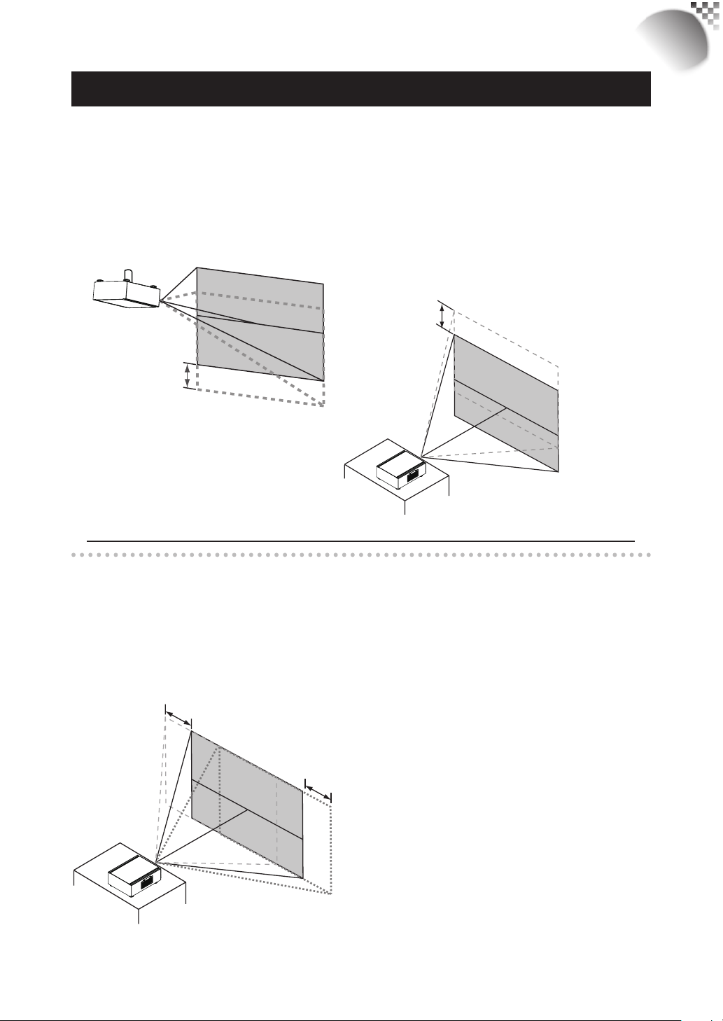
Horizontal and vertical lens shift
In addition to using the adjustable feet to adjust projection angle, you can also use the Lens
Shift function to adjust the projected image.
Moving the lens vertically
The distance of vertical lens movement is +110% , -70% of half the screen height in both
directions.For instance, if you are using a 80" × 50" screen, you will be able to move the
image upwards no more than 27.5'' or downwards no more than 17.5''.
lens shift
adjustment
Range of vertical
lens shift adjustment
RLM
W12
Moving the lens horizontally
The distance of horizontal lens movement is 30% of half the screen width in both directions.
For instance, if you are using a 80" × 50" screen, you will be able to move the image left or
right by no more than 12".
This illustration shows normal
vertical lens shift without the
use of special specifi cation
lens or projector.
Note:Please make sure the center of lens is retangular to the center of the ccreen.
horizontal
lens shift
adjustment
This illustration shows normal
horizontal lens shift without the
Range of
horizontal
lens shift
adjustment
use of special specifi cation lens
or projector.
Note: when the lens is in the
neutral position (i.e. without
horizontal or vertical shift),
the center of the projection
should be aligned with the
center of the screen.
19
Page 20

RLM
S-VIDEO VIDEO YUV 1
RGB-S
RGBHV / YUV 2
G/Y B/Pb R/Pr H V
W12
Installing the projector
Connecting the projector to other devices
HDMI / DVI connection
Signals from image source offer the best projection image quality when sent through HDMI.
Therefore, try to use input devices with HDMI output as the source of image.
HDMI/DVI input source
(BD/HD-DVD/DVD player, HD set-top-box,
gaming consoles and so forth)
12V Trigger connection
If your home theatre system includes a projector screen, screen cover or other 12V Trigger
equipment,
please connect such device/equipment to the projector’s 12V Trigger output as illustrated.
After you have done so,
Your screen will lower automatically whenever you turn on your projector for your
convenience.
Retractable screen or other
12V device
Sleeve = Ground
Tip = +12V
RS-232
HDMI
HDMI
12V TRIGGER
350mA
RGB-HV/SOG
IR ext.I II
20
Page 21

Installing the projector
RGB connection
Connect your PC or other devices with RGB output to the RGB input connectors on the
projector to be used as the source of image input.
Desk Top or Notebook
桌上型或是筆記型電腦
RLM
W12
G/Y B/Pb R/Pr H V
G/Y B/Pb R/Pr H V
Desk Top or Notebook
21
Page 22

RLM
O
N
l
PO
WER O
F
F
▲
▼
▲
▼
USER
M
EMO
R
Y
SOURCE
W12
Installing the projector
RGBs connection
If the source equipment uses composite image synchronized connectors to output
RGB, please connect the green, blue and red connectors to the Y, Pb, Pr jacks at the
COMPONENT1/SCART inputs and the synchronized output to the VIDEO jack.
Synchronize
Green Blue Red
DVD player or other SCART
RGBS input sources
S-VIDEO VIDEO YUV 1
RGB-S
YUV 1
IR INPUT connection
If the projector is unable to pick up the IR signals from the remote controle due to distance or
obstacles (i.e. wall or cabinet doors), you can connect an external IR repeater to the projector’s
IR INPUT jack to extend the effective signal reception range.
IR sensor
IR repeater
12V TRIGGER
RS-232
350mA
IR ext.I II
Remote control
RGB-S
S-VIDEO VIDEO YUV 1
HDMI
HDMI
22
G/Y B/Pb R/Pr H VRGB-HV/SOG
RGBHV / YUV 2
Page 23

Installing the projector
S-Video/Video connection
If the image input device offers both S-Video and Video connection, it is recommended that
you choose S-Video to obtain better image quality.If both the S-Video and Video inputs are
connected to the projector, the projector will prioritize S-Video signal input and image from
the Video input will not be played.
10/100 BASE-T
RS-232
12V TRIGGER
350mA
S-VIDEO VIDEO YUV 1
IR ext.I II
RGB-S
RLM
W12
G/Y B/Pb R/Pr H VRGB-HV/SOG
RGBHV / YUV 2
IN OUT
SDI / HDSDI / 3G
HDMI
HDMI
DVD player, VCR, satellite receiver,
LD and so forth
COMPONENT connection
Take the 3/5 cabled RGB component video connectors from the source equipment to the
projector’s COMPONENT1 SCART or COMPONENT2 jacks.
Y Pb Pr
RS-232
12V TRIGGER
350mA
S-VIDEO VIDEO YUV 1
IR ext.I II
RGB-S
HDMI
HDMI
G/Y B/Pb R/Pr H VRGB-HV/SOG
RGBHV / YUV 2
DTV
DTV set-top-box or other compo (YPbPr)
nent (YPbPr) input source
23
Page 24

RLM
W12
Installing the projector
STEREO DVI Connection
IR EMITTER
3D Glasses
E
M
I
T
T
E
R
L
/
R
s
i
g
n
a
l
s
L
/
R
S
y
n
c
l
s
a
i
g
n
D
V
I
Connect the STEREO DVI to a stereo 3D source – it is usually a computer with 3D Graphics
card, and 3D applications.
k
D
n
i
u
L
a
l
3D mode
There are few ways to go to the 3D mode
- OSD menu: Go to Main Menu “Input > Input Selection”, and select STEREO DVI
- Remote control: Press hot key “5” to go to STEREO DVI directly
- Network Webpage: Go to “Source/general” > “Source” and select STEREO DVI
- RS232 Commands : Use “ Input.sel = 9” to select STEREO DVI
2D mode
Please note that OSD menu is not available in 3D mode. The ways to switch back to 2D
mode are:
- Remote control: Press any of the input key 1-4 will switch back to 2D mode.
- Network Webpage: Go to “Source/general” > “Source” and select any other source that
are available.
- RS232 Commands: Use “ Input.sel = 1-8” to select any other source that are available.
24
Page 25

Installing the projector
Turning on the projector
Refer to the instructions covered in “ Page 14 : Quick installation of the projector. “.
Changing OSD language
By factory default, the OSD menu of the projector is displayed in English. If you
wish to switch to a different language, you can go to MENU CONTROL
Language and choose the language you prefer for the OSD.
RLM
W12
25
Page 26

RLM
W12
Installing the projector
Adjusting screen orientation
By default, the projector is confi gured for “frontal projection - desktop installation”. If you
choose to install your projector in other setups, be sure to adjust the screen orientation to
achieve the correct projection mode.
Front projection - ceiling mode
Press MENU ALIGNMENT Ceiling Mode and choose ON; the projector is now
confi gured for “frontal projection - ceiling mode”.
Correct Picture
canoe
26
canoe
canoe
Page 27

Rear projection - desktop installaion
Press MENU ALIGNMENT Rear Projection and choose ON; the projector is now
confi gured for “rear projection - desktop installation”.
RLM
W12
Correct Picture
canoe
canoe
Rear projection - ceiling mode
Press MENU ALIGNMENT Rear Projection and choose ON;
press MENU once more ALIGNMENT Ceiling Mode and choose ON
Correct Picture
canoe
canoe
canoe
canoe
Adjusting the projector lens
Projector lens adjustment includes focus, zoom, horizontal/vertical image shift. Please
refer to Page 15 : “5. Adjusting the projector’s angle”., “6.Adjusting focus and zoom.”. and “7.
Correcting keystoning caused by projection angle”. for detailed instructions.
27
Page 28

RLM
W12
Using the remote control
4 = YUV1
5 = Stereo DVI
1
INPUT
3
1
4
2
3
5
2
4
MENU
6
PAUSE TEXT
7
1
PHASE COLOR TINT
ASPE CT
RATI O
AUTO IMAGE
SHARPN
ADDRESSSWAPPIP
5
You can confi gure the input source
that corresponds to each button in
the OSD Menu. To do so:
When press MENU > CONTROL > Button
1~5; use the ▼▲ buttons to choose from
diffferent sources of input. You can choose
from: HDMI 1,HDMI 2,RGB D-15,YUV
1,RGBHV/YUV 2,Composite Video,S-Video
and RGB-S.
1
For example, if you have confi gured
as
RGB D-15 in the OSD Menu, when you press
1
on the remote control, the projector will
display the image from RGB D-15.
4. ▼▲▲▲
Use these buttons to make your
selection or confi gure, adjust
confi guration or toggle between
image displays.
ENTER
Use this button to select items in the
menu or confi rm the settings you
have changed.
When press ENTER , You also recall
LENS ADJUST when menu is off.
28
1. ON
This button is used to turn on the
projector.
2.
OFF
This button is used to turn off the
projector.
1
2
3
3.
4 5
These buttons on the remote control
are the hotkeys for different image
source. By factory default, these are:
1 = HDMI 1
2 = RGB D-15
3 = RGBHV/YUV2
5. ASPECT RATIO
You can scroll through different
aspect ratios by pressing this button
repeatedly. For more information,
refer to " Page 38 : Aspect Ratio ".
6. MENU
Press this button to show or hide the
OSD Menu.
7. Various image adjustment buttons
PAUSE
PAUSE
Use this button to halt projection
temporarily.
TEXT
TEXT
When TEXT is set to ON, the
user will be able to operate the
OSD Menu normally.
When TEXT is set to OFF, only
ON, OFF, 1~5, SWAP, PIP,
Page 29

Using the remote control
RLM
W12
PAUSE will function normally;
pressing any other buttons will
not access the OSD Menu.
8.
AUTO IMAGE
This button is used to Resync the
image; when the image signal
becomes unstable or image
quality deteriorates simply press
this button and the projector will
automatically adjust the screen
dimension, phase, timing and so
forth.(The adjustments also apply
to PIP input).
CONTRAST
Adjust the level of white in the
image to increase or decrease
image contrast.
BRIGHTNESS
Adjust the level of black in the
image to increase or decrease
image brightness.
SHARPNESS
Adjust image sharpness and
clarity.
PHASE
When the image fl ickers, doubles,
distorts or appears to be wavy,
press this button to adjust.
COLOR
Adjust the image’s color saturation
When oversaturated, the colors in
the image will appear to be very
bright and vivid; on the other hand,
if colors are undersaturated, the
image will appear to be washed
out.
TINT
This button only works for video
signals input through the Video
and S-video ports. By pressing
this button, you can adjust the
ratio of magenta and green in the
image; lowering this setting will
make the image appear more
magenta, while increasing this
setting will make the image
appear more green.
PIP
PIP
Use this button to display or
disable PIP.
SWAP
SWAP
Use this button to switch the
sources of image PIP display.
ADDRESS
ADDRESS
*Only 2 addresses are possible*
Press and hold the ENTER buton
and press this button until the
remote control panel fl ashes once
(approximately 5 seconds) to
change the receiving address of
the remote control. If you use one
remote control to operate two
different projectors, you can
assign different address for the
two projectors so that when you
operate projector A, projector B
will not be affected.
29
Page 30

RLM
W12
OSD Menu description
OSD Menu Tree
Tree
HDMI1
HDMI2
RGB D-15(RGB-HV/SOG)
YUV1(RGB-S)
RGBHV/ YUV2
Composite Video( Video)
S-Video
RGB- S
SDI/HDSDI/3G
STEREO DVI
Auto
48Hz, 50Hz, 60Hz
On
Off
On
Off
Logo
Blue
Black
White
Auto
PAL, SECAM, NTSC
Off, Auto
Always
3200K, 5400 K, 6500 K,
9300 K, Native
Black Balance Offset
Red Offset
Green Offset
Blue Of fset
White Balance
Red Gain
Green Gain
Blue Gain
5:4 , 4:3, 16:10
16:9, 1.88, 2.35
Letterbox, Native
H Total
H Start
H Phase
V Start
INPUT
IMAGE
Input Selection
Input Locking
Auto Power Off
Auto Power ON
No Signal
Video Standard
Auto Image Adjust
Contrast 0~200
Brightness 0~20 0
Saturation 0~200
Tint 0~200
Sharpness 0~200
Noise Reduction 0~200
Color Temperature
Input Balance
Aspect Ratio
Timings
Auto Image Execute
OSD Menu
LAYOUT
LAMPS
Zoom
Main Select
PIP Select
PIP Position
PIP On, Of f
Mode
LAMPS
High Altitude Mode
Power 0~19 (85% - 100%)
Lamp1 Status
Lamp2 Status
Lamp1 Run Time XX HRS
Lamp2 Run Time XX HRS
Off
Crop
Zoom
HDMI1
HDMI2
RGB D-15(RGB-HV/
SOG)YUV1(RGB-S)
YUV2(RGBHV/YUV2)
Composite Video( Video)
S-Video
RGB- S
SDI/HDSDI/3G
STEREO DVI
HDMI1
HDMI2
RGB D-15(RGB-HV/
SOG)YUV1(RGB-S)
YUV2(RGBHV/YUV2)
Composite Video( Video)
S-Video
RGB- S
SDI/HDSDI/3G
Top Left
Top Right
Botton Left
Botton Right
Split L-R
Eco
Normal
Power
Single
Dual
On
Off
On
Off
On
Off
30
Page 31

OSD Menu description
RLM
W12
ALIGNMENT
Control
Rear Projection
Ceiling Mode
Lens Control
Dynamic Contrast
Gamma
Internal Patterns
Color Space
Lens To
Midposition
Warp
Blanking
ScenergiX
IR Address
Eco Network Power
Network
On
Off
On
Off
Zoom/Focus
Shift
On
Off
1.8 2.0 2.2
2.35 2.5
On (1~12 Pattern)
Off (0 of f)
Native, EBU, SMPTE
Custom
Execute
Horizontal Keystone
Vertical Keystone
Rotation
Pincushion / Barrel
Top Left Corner
Top Right Corner
Bottom Left Corner
Bottom Right Corner
Top, Bottom
Left, Right, Reset
Status
White Level
Top
Bottom
Left
Right
Black Level
Top
Bottom
Left
Right
ALL
RED
GREEN
BLUE
Reset
Adjust Lines
1
2
On
Off
IP Address
Subnet mask
Gateway
DHCP
(these are read-only
information)
Control
Service
Top Left
Top Right
Menu Position
Start Up Logo
Start Up Chime
Button 1
Button 2
Button 3
Button 4
Button 5
Trigger 1
Trigger 2
Auto Source
Language
Model
Serial Number
Software Version
Active/PIP source
Pixel Clock
Signal Format
H/V Refresh Rate
Lamp1 Run Time
Lamp2 Run Time
Lamp Hour Reset
Projector Run Time Read- only information
Blue Only
Factory Reset
Botton Left
Botton Right
Center
On
Off
On
Off
HDMI1
HDMI2
RGB D-15(RGB-HV/
SOG)YUV1(RGB-S)
YUV2(RGBHV/YUV2)
Composite Video( Video)
S-Video
RGB- S
SDI/HDSDI/3G
STEREO DVI
5:4 , 4:3, 16:10
16:9, 1.88, 2.35
Letterbox, Native, Auto
On
Off
English
French
Spanish
German
Portuguese
Chinese Simplifi ed
Chinese Traditional
Japanese
Korean
Read-only information
Lamp1 Hour Reset
Lamp2 Hour Reset
On
Off
The command will
be executed after
confi rmation in the
prompt dialog box
31
Page 32

RLM
W12
OSD Menu description
OSD Description
1. Press the MENU button on the remote control or on the back of the projector to
bring up the OSD Menu.
2. You will see seven functional menus (Input, Image, Layout, Lamp, Alignment,
Control and Service). Press ◄ or ► to select the desired sub menu.
3. Press ▲ or ▼ to select the desired sub menu.
4. Your current selection in each of the sub menu will be displayed in yellow text and
highlighted in blue. Press ◄ or ► to access the confi guration for the selected
item or press ENTER to go to another sub menu.
5. Press MENU to return to the previous menu.
6. From the main menu, press MENU to close the OSD Menu.
INPUT
Input Selection
Inupt Configuration
Input Locking
Auto Power Off
Auto Power On
No Signal
Video Standard
Auto Image Adjust
Input Selection
Use this function to specify the source of image connected to the rear of the projector. For
instance, if you have connected your PC as the video input source,
you can choose RGB D-15(RGB-HV/SOG) to be the input for image projection.
Options of input available on the projector include: HDMI1, HDMI2, RGB D-15(RGB-HV/
SOG), YUV1(RGB-S), YUV2(RGBHV/YUV2), Composite Video(Video), S-Video, RGB-S,
SDI/HDSDI/3G. STEREO DVI.
Input Locking
Use this function to specify the frequency of the image input signal. You can let the projector
determine the optimal projection frequency or force the projector to project image at the
frequency you specify.
Auto
•
The preset value for this function is Auto. If you specify vertical refresh frequency from the
input device to be between 48~62Hz, the projector will automatically lock the frequency
of the input signal so that both signal input and output will be refreshed at the same
Enter
< ----- >
< ----- >
< Off >
< Off >
< Logo >
< ----- >
< ----- >
32
Page 33

OSD Menu description
frequency in order to achieve optimal image output. If the frequency of the input signal falls
between 24~31Hz, the projector will automatically double the vertical refresh frequency.
If the frequency of the input signal falls between 31~48Hz or exceeds 62Hz, the projector
will automatically set the frequency to 60Hz.
50Hz
•
Choose this option to set image output frequency at 50Hz.
60Hz
•
Choose this option to set image output frequency at 60Hz.
Note: If you enable PIP, the projector will automatically synchronize the frequency of the PIP input signal
with the main input signal.
Auto Power Off
The default value is OFF. If you set it to ON, the projector will automatically shut down after
20 minutes without input signal.
Auto Power ON
The default value is Off.If you set it to ON, the projector will automatically start up when it is
connected to AC power. If you plug the projector’s power cord into an AC socket with a switch,
you can use this function to start up the projector using the socket’s switch instead of the
remote. If you do not need this function, please set it to Off.
RLM
W12
No Signal
Use this function to specify the content or color to be displayed on the blank screen when no
input signal is available.You can choose from Logo, Blue, Black, White.The default value is
Logo.
Video Standard
Different countries may use different video signal formats. Please choose the video standard
in your area.
Auto
•
This is the default value.The projector will automatically determine the video standard used
in your area.
PAL (Phase Alternation By Line)
•
A video standard with 625 scan lines / 25 frames per second developed by Germany. The
PAL system is used in Germany, Great Britain, South America, Australia, China and many
Western European nations and Asian countries.
SECAM (Sequential Color With Memory)
•
A video standard with 625 scan lines developed by France. Areas including former East
Germany, Czechoslovakia, Egypt, Poland and etc. use the SECAM standard.
NTSC (National Television Systems Committee)
•
A video standard with 525 scan lines per frame developed by the National Television
Systems Committee of U.S.. The NTSC standard is primarily used in the U.S., Japan,
Canada and Mexico.
Note: Generally speaking, the projector will be able to automatically detect the video standard used
in your area. However, there are circumstance where the projector will fail to interpret the video
standard used and the user will have to manually confi gure the video format. If you are unsure of the
video standard used in your area, please contact a qualifi ed personnel and inquire about the video
standard used in your area.
33
Page 34

RLM
W12
OSD Menu description
Auto Image Adjust
You can confi gure the Auto Image Adjust function to one of the following three modes:
Off =NEVER
•
Auto =When not done before(or when done fi rst time)
•
Always =When new source selected or new source connected.
•
For more information on Auto Image Adjust, refer to “ Page 34 : Auto Image Adjust “.
IMAGE
Contrast
Use to adjust the contrast of the projected image.You can connect the projector to an
external image source to display an image resembling the one shown below for adjustment.
It is recommended that you adjust the projected image according to the results shown below
so that the brightness of the spectrum remains constant throughout and achieve maximum
contrast between black and white.
The following image illustrates the results of direct contrast adjustment using a random
image:
Lowered contrast Enhanced contrast
Original image
34
Page 35

OSD Menu description
Brightness
Use to adjust the brightness of the projected image.You can connect the projector to an
external image source to display an image resembling the one shown (PLUGE, Picture LineUp Generation Equipment) for adjustment. Although there are numerous versions of PLUGE
image, they are typically comprised of blocks of black, white and gray on top of a black
background.
It is recommended that you adjust the image to the
following status:
The darkest black bar of the image should
•
disappear into the background.
The dark gray area should be barely visible.
•
The light gray area should be clearly visible.
•
The white area should appear real and mellow.
•
The image should only display black, gray and
•
white (with no other colors).
Above Black
Contrast, Brightness, Saturation and Tint are interrelated options that
affect one another; when you adjust one of them, you might have to
fi ne tune other settings to get the best projection results.
Below Black
RLM
W12
The following image illustrates the results of direct brightness adjustment using a random
image:
Reduced brightness Enhanced brightness
Original image
Saturation
Use to adjust the saturation of the projected image.If the color of the projected image
seems to be overly bright and vivid, decrease color saturation; if the color seems white and
washed out, increase color saturation.
Reduced saturation Enhanced saturation
Original image
35
Page 36

RLM
W12
OSD Menu description
Tint
Use to adjust the tint (balance between magenta and green) of the projected image.
Lowering the value will make the image appear redder; increasing the value will make the
image appear greener.
Reduced tint Enhanced tint
Original image
Sharpness
The adjustment of sharpness primarily changes the value of high frequency detail. You can
connect the projector to an external image source to display an image resembling the one
shown below to adjust the image sharpness.
The following image illustrates the results of direct sharpness adjustment using a random image:
Reduced sharpness Enhancedsharpness
Original image
36
Page 37

OSD Menu description
Noise Reduction
Use to adjust the noise of the projected image. This function is suitable for the
elimination of image noise from interleaving SD input.Generally speaking, reducing image
noise will lower the value of high frequency detail and make the image appear more mellow.
→
noise reduction
Color Temperature
You can choose from 3200K, 5400K, 6500K, 9300K and Native.
Color temperature refers to the change in light color under different energies that is perceived
by the naked eye.The change of color temperature from low to high for visible light goes from
orange red white blue
The projector’s default color temperature is set at 6500K and it is suitable for most situations.
As color temperature rises, the image will appear to be more blue; as it decreases, the image
will appear redder.When you choose “Native”, the projector will disable the white adjustment
function of the input device.
.
RLM
W12
Input Balance
Regardless of the change in ambient light, the human eye is equipped with an automatic
adjustment mechanism that makes a white object appears white and black object black.
However, since no machine has such an incredible innate feature, you may need to make
certain adjustments to the projector’s settings when the ambient light changes so that the
image will appear closer to the actual colors.
input
signal
the point where CUT off
for RGB is reached
needs to be the same
the point where saturation
is reached needs to be same
for RGB
0
black balance adjust
Offset
This refers to the control of color imbalance in the darker areas of the projected image.It is
recommended that you use an external test image with many areas of dark and gray colors
(i.e. an image of 30IRE-window). If you notice minimal amount of red, green or blue in the
gray areas, adjust the offset of the corresponding color accordingly.This function will shift the
entire color spectrum for the whole image and change its brightness.
White balance
adjust
255
37
Page 38

RLM
W12
OSD Menu description
Gain
This refers to the control of color imbalance in the brighter areas of the projected image.It is
recommended that you use an external test image with many areas of white (i.e. an image of
80IRE-window). If you notice minimal amount of red, green or blue in the gray areas, lower
the gain of the corresponding color accordingly.This function is used to increase or decrease
the range of color input for the entire image.
Generally speaking, as gain increases, the contrast of the image will become lower.By
increasing the offset, the image brightness will become lower.
Black Balance Offset
•
This function involves the adjustment of the following red, green and blue offsets. The text
itself is decorative.
Red Offset
•
Press to adjust the offset of red in dark scales.
Green Offset
•
Press to adjust the offset of green in dark scales.
Blue Offset
•
Press to adjust the offset of blue in dark scales.
White Balance
•
This function involves the adjustment of the following red, green and blue gains. The text
itself is decorative.
Red Gain
•
Press to adjust the gain of red in bright scales.
Green Gain
•
Press to adjust the gain of green in bright scales.
Green Gain
•
Press to adjust the gain of blue in bright scales.
Aspect Ratio
Use this function to adjust the aspect ratio of the projected image. Use to adjust the ratio
of image length and width.
The projector’s full image size is 16:10 (1920×1200 dots).The following diagram illustrates the
difference in various aspect ratio settings:
Native input
16:10
Output aspect ratio
1.88
Output aspect ratio
5:4
Output aspect ratio
2.35
Output aspect ratio
4:3
Output aspect ratio
Letterbox
Output aspect ratio
16:9
Output aspect ratio
Native
38
Page 39

Output aspect ratio
Output aspect ratio
OSD Menu description
RLM
W12
Native input
4:3
Output aspect ratio
1.88
Output aspect ratio
5:4
Output aspect ratio
2.35
Output aspect ratio
4:3
Output aspect ratio
Letterbox
16:9
Native
Cropped portion of the image
Note : that when used for commercial purposes, including: projection of image in movie theatres, hotels,
cafeteria and other public venues, compression or extension of image achieved through the change of
aspect ratio may constitute copyright infringement to the rightful owner of the image. Please do so at your
own discretion.
Timings
H Total
•
Press to adjust the horizontal total.
Use this function to adjust the clock frequency of pixel sampling (horizontal pixel frequency
of the analog input source generated by the ADC). If you notice fl ickering or verticle lines
in the image, it means that the pixel sampling frequency is insuffi cient. You can use this
function to adjust the frequency to achieve consistent image quality.
The following image is an example of test image from an external signal source:
*In order to adjust timings the pattern should be used is pixel (on/off)*
H Start
•
Use to adjust the projected image’s horizontal position.
If the projected image is not at the center of the screen (i.e. shifted to right or left) and
ends up being cropped, use this function to adjust the image’s horizontal position.The
following image is an example of test image from an external signal source:
Adjust image quality by
changing the value of horizontal
total to smoothen the image.
39
Page 40

RLM
原始圖面 圖面下偏
圖面上偏
W12
OSD Menu description
Native picture Skewed left
Skewed right
H Phase
•
Use to adjust the projected image’s phase.
Use this function to adjust the phase of pixel sampling clock (relative to input signal).
Should the image still fl icker or show noise (i.e. edges on texts) after optimization, adjust
phase accordingly.
V Start
•
Use to adjust the projected image’s vertical position.
If the projected image is not at the center of the screen (i.e. shifted up or down) and ends
up being cropped, use this function to adjust the image’s vertical position.The following
image is an example of test image from an external signal source:
Native picture
Skewed down
Skewed Up
It is recommended that when adjusting the image, the horizontal total should be adjusted before the horizontal phase.
However, if the image still fl ickers even after you have adjusted both, try lowering the image noise.
Auto Image
When Auto Image was selected in the OSD menu, press ENTER to execute the automatic
image adjustment function.
By executing this function, the projector will resync the image. Use this function when the
image source is unstable or when you notice deterioration in image quality and the projector
will automatically adjust the image size, phase and timing. (The adjustment also applies to
PIP input source).
This function is identical to the
key on the remote control to execute this function.
button on the remote control. You can simply use the hot
40
Page 41

OSD Menu description
LAYOUT
Zoom
Due to the fact that some consumers may still be using older television systems, some TV
programs may not display the edges of the image. Use this function to hide the image edge
by choosing one of the following three options:
Off
•
Setting it to off makes no change to the projected image.
Crop
•
Setting it to "Crop" will add two "masks" equivalent to 3% of horizontal resolution on either
side of the image and two similar masks above and below the projected image.
Zoom
•
You can use this function to enlarge the image's horizontal resolution over the 106% of the
default aspect ratio. Any portion that exceeds the original image will be cropped.
RLM
W12
When you set aspect ratio to "Native", be sure to set Zoom to "Off" or "Crop".
Off Crop Zoom
16:10
5:4
2.35
Main Select
When you want to project PIP image, use this function to specify the image source for the
PIP image. This function is identical to Input Selection; for more information, please refer to "
Page 32 : Input Selection ".
41
Page 42

RLM
W12
OSD Menu description
PIP Select
Sub picture
Use this function to select the source for the sub window.
You can choose from HDMI1, HDMI2,
RGB D-15(RGB-HV/SOG), YUV1,
RGBHV/YUV2, Composite Video(Video),
S-Video, RGB-S, SDI/HDSDI/3G and so forth.
PIP Position
You can choose to display
the sub window in fi ve different location
over the main picture according
to your preference.
Split L-R
Main picture
Top RightTop Left
Bottom RightBottom Left
PIP
If you wish to display PIP image, you can make the confi guration here.By choosing "ON", you
will see two windows on the projected image; the larger one is the primary image and the
smaller one is the sub image.By choosing "OFF", the PIP function will be disabled and you
will only see a single image window.
*please refer to the following main and PIP source matrix for a valid main and PIP source selection when PIP is ON.*
Pip/main source
42
availability
HDMI1
HDMI2
RGB(D15)
YUV1
RGBHV/YUV2
PiP select
Composite Video
S-Video
RGB-S
SDI/HDSDI/3G
Source availabe
HDMI1
-
-
HDMI2
-
-
-
source not availabe
RGB
(D15)
-
- -
Main select
YUV1
-
-
RGBHV/
YUV2
-
-
-
Composite
Video
-
-
S-Video
RGB-S
SDI/
HDSDI/3G
-
-
-
-
-
-
-
-
Stereo DVI
-
-
-
-
-
-
-
-
-
Page 43

OSD Menu description
LAMP
This chapter covers information on the projector lamp.
Mode
ECO
•
When set to Eco mode, the wattage of the lamp will be at 320W. If the surrounding
environment is suffi ciently dark or if you do not require intense brightness, you can set the
lamp to Eco mode to prolong its usage life.
Normal
•
When set to Normal mode, the wattage of the lamp will be at 400W. If the projection
environment requires brighter image, you can set the lamp to Normal for the highest
projection brightness.
Power
•
If the image brightness at Eco mode is too dark for you and the Normal mode gets too
bright, you can set it to Power to specify the power of the lamp yourself to make fi ne
adjustments to the brightness of the projected image.you could encounter situations where
the image from projector A being brighter than projector B. When this occurs, you can
use this function you could encounter situations where the image from projector A being
brighter than projector B. When this occurs, you can use this function to fi ne tune the
brightness of the two projectors to achieve consistent image brightness. To access this
function, go to the OSD Menu → LAMPS → Power and adjust accordingly.
RLM
W12
LAMPS
Depending on the application condition, either single lamp or dual lamps can be selected via
OSD menu. When the projector was switched from single lamp to dual lamps, an hourglass
OSD will block the user from the further OSD operation for 7 seconds. When the projector
was switched from dual lamp mode to single lamp, the lamps selection OSD will be blocked
for 90 seconds for lamp cooling. The lamp power can be adjusted from 80% ~ 100%.
Single
•
When the projection environment is suffi ciently dark
that a single lamp could achieve the desired projection
brightness, you can choose to use one single lamp.
The projector will automatically determine the usage
hours for lamp1 and lamp2 and choose the lamp with
lower hours for the operation.
Dual
•
When you require brighter image from the projector,
please operate the projector with Dual lamps.
Lamp1
Lamp2
43
Page 44

RLM
W12
OSD Menu description
High Altitude Mode
Use this function to control the projector's cooling fan. You can set it to Off or On. The default
setting is Off.
Under normal circumstances, the projector will operate normally with this function set to
Off. By default, the projector will detect the temperature of the surrounding environment to
regulate the speed of the cooling fan. When the ambient temperature rises, fan speed will
increase (generates louder noise) to make sure the heat inside the projector gets discharged
and keep the projector working normally.
However, if you were to operate the projector in environment of excessive heat or in areas of
high altitude, the projector may automatically shut down. When this happens, you can enable
this function by setting it to On to force the cooling fan to work at a higher speed to regulate
the temperature inside the projector.
High altitude region refers to area with elevation over 1500 meters (4900 feet).
•
When operating in normal altitude environments, the projector will adjust the cooling fan
•
according to the temperature of the working environment. When the temperature rises
above 30C, the projector will automatically increase fan speed.
According to the product specifi cation, the maximum operating altitude for the projector is
•
at 3000m@25C.This means that you should not be operating the projector in high altitudes
when the working environment is over 25C.
(Due to the air thinning substantially at high altitudes, the result of cooling achieved by
the cooling fan is signifi cantly reduced compared to operation on level ground. With low
atmospheric pressure and high operating temperature, the cooling fan will not be able to
disperse the heat adequately)
Power
This function will not be available if you have set the lamp to Eco or Normal modes, refer to "
Page 43 : Mode ".; you can only adjust this setting when the lamp has been set to ”Power”. You
can specify the lamp power in the range of 85% ~ 100%. Generally speaking, the lower the
power, the dimmer the image will be but the lamp will have longer lifecycle. In contrast, the
higher the power, the brighter the image will be at the cost of shorter lamp lifecycle.
Lamp1 Status
This function is limited to display purposes to inform the user of Lamp1 status (On or Off).
Lamp2 Status
This function is limited to display purposes to inform the user of Lamp2 status (On or Off).
Lamp1 Run Time
This function is limited to display purposes to inform the user of Lamp1's total run time.
Lamp2 Run Time
This function is limited to display purposes to inform the user of Lamp2's total run time.
44
Page 45

OSD Menu description
ALIGNMENT
Rear Projection
The default setting is Off.
Whenyou have set up the projector for rear projection, please set it to ON. For more
information on different modes of projection, refer to " Page 17 : Modes of installation ".
RLM
W12
Ceiling Mode
The default setting is Off.
Whenyou have set up the projector for ceilingmode (hung from the ceiling in reverse), please
set it to ON.For more information on different modes of projection, refer to " Page 17 : Modes
of installation ".
Lens Control
Zoom
•
This function is identical to the one covered in previous sections. Refer to " Page 15 :
6.Adjusting focus and zoom. ".
Focus
•
This function is identical to the one covered in previous sections. Refer to " Page 15 :
6.Adjusting focus and zoom. ".
Shift
•
This function is identical to the one covered in previous sections. Refer to " Page 15 : 5.
Adjusting the projector's angle ".
Keystone
Use this function to correct keystoning caused by projection angle.
Horizontal Keystone
•
This function is identical to the one covered in previous sections. Refer to " Page 16 : 7.
Correcting keystoning caused by projection angle ".
Vertical Keystone
•
This function is identical to the one covered in previous sections. Refer to " Page 16 : 7.
Correcting keystoning caused by projection angle ".
Note : * The summation of the absolute value of horizontal keystone and vertical keystone is limited to
less than or equal to 350. *
45
Page 46

RLM
W12
OSD Menu description
Dynamic Contrast
Use this function to confi gure the projector to automatically adjust image contrast from the
source upon start up or shut down. When activated, the projector will dynamically adjust the
image contrast from the beginning of the projection until the content has ended.
Gamma
Different Gamma settings will affect viewers' perception of the image. Generally speaking,
for images that are darker, it is recommended that Gamma be set higher to yield better image
quality in darker regions by sacrifi cing details in brighter areas. In contrast, when projecting
brighter images, you can set the Gamma lower to give up details in the darker areas to make
the brighter areas (i.e. clouds) more visible.
You can choose from fi ve different gamma settings (1.8, 2.0, 2.2, 2.35 and 2.5) on the
projector. The projector's default gamma value is at 2.2.
Every setting has precisely defi ned phases to display all primary colors (red, green, blue) and
secondary colors (yellow, cyan, magenta) in millions of pixels. Changing any number in the
setting will change the resulting color and rearrange the color "triangle".
Internal Patterns
The projector comes with some standard built-in patterns for testers to calibrate the
equipment. These include:
0 = Off 1 = Color Bars 2 = Hatch 3 = Burst 4 = Red
5 = Green 6 = Blue 7 = White 8 = Black 9 = TI-Red
10 = TI-Green 11 = TI-Blue 12 = TI-Ramp
Color Space
Using different color space will create different color presentation in the projected image. You
can choose from the following color gamma:
Native
•
Choose this to apply the projector's native color gamut
EBU
•
Choose this to apply the EBU color gamut; it is primarily suited for input devices using
PAL, SECAM, 576i, 576p and so forth.
SMPTE
•
Choose this to apply the SMPTE color gamut; it is primarily suited for input devices using
NTSC, 480i, 480p and so forth.
Custom
•
Choose this to customize the color gamut according to your preference through projector
Toolset application.
Lens To Midposition
After series of lens shift operations, this function can be used to return the lens to the
center position.
46
Page 47

OSD Menu description
Warp
The function provides distortion correction on projected images.
Horizontal Keystone
•
Press ▲▼ to correct horizontal keystone due to projection angle.
Please refer to " Page 16 : 7. Correcting keystoning caused by projection angle ".
Verticall Keystone
•
ress ▲▼ to correct Vertical keystone due to projection angle. Please refer
P
to " Page 16 : 7. Correcting keystoning caused by projection angle".
• Rotation
Press ◄ ► to correct incorrect image angle.
Press ◄ to adjust angle to
correct.
Pincushion / Barrel
•
Press ◄► to correct pincushion/barrel distortion.
Correct angle
Press ► to adjust angle to
correct.
RLM
W12
→
Press ◄► to
correct pincushion
distortion to correct
image.
→
Press ◄► to
correct barrel distortion
to correct image.
Top Left Corner
•
Press ◄► to correct top left corner image bias.
→
Press ◄► to correct
top left corner image
bias to correct image.
47
Page 48

RLM
W12
Top Right Corner
•
Press ◄►to correct the right corner image bias.
→
Press ◄► to correct
top right corner image
bias to correct image.
Bottom Left Corner
•
Press ◄►to correct the bottom left image bias.
→
Press ◄► to correct
bottom left corner
image bias to correct
image.
Bottom Right Corner
•
Press ◄►to correct the bottom left image bias.
OSD Menu description
Press ◄► to correct
bottom right corner
image bias to correct
image.
Blanking
TOP
•
Press ▼▲ on the remote control to
adjust the top blanking area onthe
projected image
Bottom
•
Press ▼▲ on the remote control to adjust
the bottom blanking area on the projected
image
Right
•
Press ◄► on the remote control to adjust
the right blanking area on the projected
image
Reset
•
It will reset all the blanking functions to the
default settings that is without any blanking
fuctions enabled.
→
Use left blanking
function to block
the additional
image on the
screen.
48
Page 49

OSD Menu description
ScenergiX
The function of ScenergiX is applied in multiple projectors that are projecting at the same
screen simultaneously to adjust the uniformity of the images on the screen.
Status
•
Press ENTER to select ON or OFF. The function must be set to ON in order to enable the
function of ScenergiX. If the function is set to OFF, the function of ScenergiX is disabled.
White Level→ white level is to set the line from one projector where the other projector last
•
pixel ends. Press▲▼◄► to adjust the white level of the Top. Bottom, Left, Right direction on
the projected image.
As shown in the below drawing, the area D is the overlap area of the projected image 1 and the projected
image 2. The white level lines that is set where the other projector last pixels ends. Color adjustment for
matching the images is done with projector toolset with customs color space x and y or with input balance
on the OSD.
Black Level→ the purpose of black level is in order to compensate the non overlap zones
•
vs the over lap zone. It increase the black level to the brightness level of the overlap black.
It is to adjust the black level of the Top, Bottom, Left, Right direction on the projected
images.
It can be set to adjust the primary color of the projector. For instance, select ALL is to
adjust the primary color of Red, Greed, and Blue. Or it can be set to adjust the Red, Green
and Blue independently.
Note: The function combination of Black Level adjustment and 4 Corners is not available
Note: The function combination of Black Level adjustment and blend along corners is not available.
A B C
A B C
White Level Lines
White Level Lines
D
D
Image 1
Image 1
Image 2
Image 2
for black level adjustment a black image
needs to be connected on the 2 projectors.
Zone B will have the sum of the blacks
of the 2 projectors. Set the adjustment
line of the black level to the position
where the non active DMD's of the
right projector ends. Set the adjustment
line of the black level to the position
where the non active DMD's of the
left projector ends. Adjust black level
of projector A to match the black level
with zone B. Adjust the projector C to
match the black level with zone B.
RLM
W12
Blend along
corners
Reset
•
The function can reset the ScenergiX settings on the projector. It will restore to the
images to the default that is without any ScenergiX functions enabled.
Adjust Lines
•
When the function is ON, there will be adjust lines on the image in order to easily adjust
multiple images. Press ▼▲◄► on the remote control to adjust the position of the lines on
the image.
The image below is an example if 2 projectors are projecting at the same image.
1. Horizontally place two projectors and have the two projected images with an
overlap area and use the focus/zoom and lens shift functions with test grid
pattern to set a proper overlap area for blending with a matched grid size.
49
Page 50

RLM
XXX
X
W12
OSD Menu description
Color matching 2 projectors on white is done with P7 (R.G.B.C.M.Y.W) adjust in projector
2.
toolset.
3. Brightness matching 2 projectors can be done with the lamp power(Refer to
adjustment by dimming the projector with higher lumens.
4. Use ScenergiX-> White level to set the blending size based on the overlap
region size.
Use ScenergiX-> Black level position to adjust the start position of black level
compensation.
Use ScenergiX-> Black level to raise the brightness of non-overlap zone such
that the brightness of the overlap zone and non-overlap zone are matched for
black level.
Note1: Please note that the following allowable warp, blanking and ScenergiX combination
based on the underlying chip specifi cation
Note2: ScenergiX / 4 corner combination is available when black level is not adjusted.
Note3: Blend along corners is available when black level is not adjusted.
Keystone Rotation Pin/Barrel 4-corner blanking
Keystone X X X X X X X
Rotation X X X X X X X
Pin/Barrel X X X X X X X
4-corner
blanking X X X OK OK OK OK
White Level
ScenergiX
Black Level Black Level
Top/Bottom or
Left/Right only
Blend along corners X X X OK OK X
X X X OK OK OK
X X X X OK OK X
OK OK OK
Top/Bottom or
Left/Right only
ScenergiX
White Level
Blend along corners Black Level
Black Level
50
Page 51

OSD Menu description
CONTROL
RLM
W12
IR Address
Use this function to confi gure the projector’s IR code receive commands from the remote
control. The default value is 1.If you have other equipment in your home that could pick up
the command from the projector’s remote control, it is recommended that you set the remote
control code to 2.
When you are running two projectors via serial connection, you can set the code on one
projector as “1” and “2” for the other projector. By doing so, you will be able to control two
projectors with the same remote control.
When you want to switch your remote control from code 1 projector to code 2 projector,
press and hold the ENTER and ADDRESS buttons on the remote control simultaneously (for
approximately 5 seconds); the backlight module on the remote control will blink to confi rm the
switch.
Eco Network Power
The projector can be connected to a network via its RS-232 port and 10/100 BASE-T port
for remote operation with two separate boards to control the signal sources from RS-232 and
10/100BASE-T ports.
If you do not require remote operation of the projector over a network, it is recommended that
you set this function to On to activate the ECO Network Power. This will turn off the power
that is used to control the 10/100 BASE-T board. However, you will not be able to operate the
projector remotely over a network as long as the function remains activated.
By setting it to Off, the function will be disabled. You won’t be able to conserve power but you
can control the projector remotely over a network.
51
Page 52

RLM
W12
Network
To control the projector via network, after connecting the network cables for a PC and the
projector, you can use this OSD function to view the relevant network information (such as IP
Address, Subnet Mask, Gateway and DHCP) of the projector. Please confi gure the PC to be
connected to the projector with a proper IP address with the same subnet mask, gateway as
the projector. The default IP address of the projector is 192.168.0.100. The network settings
of the projector can only be changed through the web-page control or projector Toolset
application.
To control the projector via network, please connect to the projector via a web browser with
the IP address shown on the OSD menu CONTROL -> Network. The home page will be
displayed as follows.
W12
Menu Position
You can use this function to designate which area on the image the OSD Menu will appear.
As you can see from the diagram below, there are fi ve positions where you can choose to
have the OSD Menu displayed.The default setting is “Center”.
Top Left
Center
Bottom Left
Top Right
Bottom Right
Start Up Logo
You can use this function to have the projector display the Barco logo in the start up screen.
Set On to display the Barco logo during start up and Off to display a blank image.
52
Page 53

OSD Menu description
Start Up Chime
Set it to On to have the projector play a sound effect during start up; when it is set to off, the
projector will not play any sound effect to indicate start up.
Button 1~5
Use this function to designate the image source for each corresponding button.
For example, if you have assigned Button 1 as HDMI1 and Button 2 as RGB-S,
when you press
when you press
RGB-S.
You can choose from eight different input sources on the projector, namely: HDMI1, HDM2,
RGB D-15(RGB-HV/SOG), YUV1(RGB-S), YUV2(RGBHV/YUV2), Composite Video(Video),
S-Video, RBG-S, SDI/HDSDI/3G, and STEREO DVI.
1
on the remote control, the projector will show the image from HDMI1.
1
on the remote control, the projector will switch to the image from
Trigger1 ~2
The projector comes with two sets of Trigger output. You can confi gure two different devices
connected to the projector via the trigger ports to be automatically turned on when the
projector is on. There will be a 2-3 second delay prior to activation to prevent operation of this
function when the user is choosing the desired aspect ratio.
5:4 Outputs 12V of power on Trigger1 or 2 when the user chooses the 5:4 aspect ratio.
4:3 Outputs 12V of power on Trigger1 or 2 when the user chooses the 4:3 aspect ratio.
16:10 Outputs 12V of power on Trigger1 or 2 when the user chooses the 16:10 aspect ratio.
16:9 Outputs 12V of power on Trigger1 or 2 when the user chooses the 16:9 aspect ratio.
1.88 Outputs 12V of power on Trigger1 or 2 when the user chooses the 1.88 aspect ratio.
2.35 Outputs 12V of power on Trigger1 or 2 when the user chooses the 2.35 aspect ratio.
Letterbox Outputs 12V of power on Trigger1 or 2 when the user chooses the Letterbox
aspect ratio.
Native Outputs 12V of power on Trigger1 or 2 when the user chooses the native aspect
ratio.
Auto Outputs 12V of power on Trigger 1 or 2 when the projector is turned on.
RLM
W12
Auto Source
Off: default setting. By enabling this function, the projector will automatically determine
the source of input every time it is turned on so that the user will not have to make the
selection on the OSD Menu.
Setting the function off will require the user to specify source of image input on the OSD
Menu in order for the projector to display the intended image.
Language
You can use this function to select the language you wish for the OSD Menu to be displayed
in. You can choose from the following nine languages:
English, French, Spanish, German, Portuguese, Simplifi ed Chinese, Traditional Chinese,
Japanese and Korean.
53
Page 54

RLM
W12
OSD Menu description
SERVICE
Service
The functions covered in this unit relate to the display of some basic information about the
projector.
*Memory of the custom timing fi les will be erased in the Factory Reset operation.*
Model: the designated model number of the projector.
•
Serial Number: the designated serial number of the projector.
•
Software Version: the version of software installed on the projector.
•
Active/PIP Source: displays the current PIP sources.
•
Pixel Clock: displays the pixel clock of the current input signal.
•
Signal Format: displays the format of the current input signal.
•
H/V Refresh Rate: displays the horizontal and vertical refresh rates for the current image.
•
Lamp1 Run Time: displays Lamp1's current run time.
•
Lamp2 Run Time: displays Lamp2's current run time.
•
*Notice! When a lamp's run time has reached 1200 hours or when you notice the projected image to be
noticeably dimmer, please replace the lamp.*
Projector Run Time: displays the projector's total operating hours.
•
Lamp Hour Reset
Use this function to reset the hours for lamp1 and lamp2 to zero.
* After replacing the lamp, remember to reset the lamp hours to ensure the accuracy of lamp hours
displayed in the OSD Menu.*
Blue Only
Enabling this option will make the projector display only blue color to facilitate the process
of image inspection for the service personnel. For detailed instructions on how to use this
function, consult a qualifi ed service personnel.
Factory Reset
Use this function to restore the confi gurations in the OSD Menu back to factory default. Note
that this function will not apply to items including no signal, network, Projector control, startup
Logo, language, High Altitute mode and lamp hours.
*When Factory Reset is executed, all source memories created by the projector (i.e. timings fi les) will be
54
erased.*
Page 55

Lamp and fi lter maintenance
Lamp replacement
The lifecycle of ordinary projection lamp
typically lasts for 1200 hours before requiring
replacement (different lamp confi gurations
will affect lamp life). From the OSD Menu,
you can go to " Page 44 : Lamp1 Run Time
". to check how long a lamp has been used.
You should also replace the lamp when the
projected image gets noticeably darker.
Contact your local dealer to purchase new
certifi ed lamps for your projector.
To replace the projector lamp
1. Turn off the projector and unplug
the power cord. Let the projector
cool for approximately 60 minutes
before removing the lamp module for
replacement.
RLM
W12
4. Grasp the metal rod on the lamp
cover and pull the lamp out.
5. Insert the new lamp in the direction
shown in the illustration into the lamp
assembly; tighten the two screws
using a screw diver and make sure
the lamp is fi rmly secured to prevent
the lamp from shaking or poor
contact.
When you turn off the projector, the lamp inside
the projector will still be very hot (approximately
200 ~ 30 0°C). If you attempt to replace the lamp
without allowing the projector to cool, you could risk
scalding yourself. This is why you should wait for no
less than 60 minutes for the lamp to cool down in
order to perform the replacement safely.
2. Loosen the lamp cover.
3. Use a screw driver to loosen the
screws as shwon in the illustration.
6. Replace the lamp cover and fi rmly
secure the two screws on the lamp
cover.
7. Reconnect power to the projector and
reset the lamp usage timer. Refer to
" Page 44 : Lamp1 Run Time "."Lamp2
Run Time".
55
Page 56

RLM
W12
Lamp and fi lter maintenance
2. Insert the new fi lter.
Replace the filter
Make sure to replace the fi lter when it is
required to keep the air intake clear of dust,
and prevent possible over temperature issue
of the projector due to the clog of fi lter.
To clean the fi lter at the ventilation slots,
refer to the following illustration:
1. Loosen the two screws on the cover
of the ventilation slot.
3. Reattach the fi lter cover and tighten
the two screws.
56
Page 57

Simple troubleshooting and defi nition of the LED indicators
The following table of fers a list of common problems with projectors and how to troubleshoot. If the recommended solutions fail to
resolve your problem, contact your local dealer to arrange for servicing; do not attempt to service the projector by yourself.
Problem Possible cause Solution
You cannot turn on the
projector
You cannot turn on the
projector after turning it off
The remote control does not
operate normally
You are able to turn on the
projector and access the
OSD Menu but no picture
appears.
You have connected the
projector to a DVD player
as the input source but the
image appears broken or split
in halves.
The picture looks dim
The image is too bright or the
bright areas are blurr y
The image appears washed
out or the dark areas appear
too bright
The image is blurry
The color of the image looks
pale
The image fl ashes
occasionally
The colors of the projected
image are out of place (i.e.
displaying red as blue)
The noise from the cooling
fan suddenly grew louder
The LED indicator on the
projector’s rear panel is
blinking in red
1. The projector may be unplugged
2. Check the AC POWER SWITCH on the back
of the projector and see if it is fl ipped to ON.
3. The AC socket may be faulty
4. The lens cover is not replaced properly
1. You will not be able to turn on the projector
within t wo minutes after you have just turned it
off.
This feature is designed to protect the lamp.
1. The batter y might have run out
2. You might have inser ted the batteries in the
wrong orientations
3. You may be operating the remote control
too far away from the projector's IR sensor
or exceeded the maximum angle of signal
reception ; there might be an obstacle
between the projector and the remote control
or there might be a source of intense light
near the IR receiver.
4. Ø 3.5mm A wired remote connector might be
connec ted to the projector's 3.5mm port.
5. The remote c ontrol's address is not consistent
with the projector's address.
1. The projector may not be turned on properly
or you have not selected the correct input
source.
2. You might not have connected the source
device correctly or the source might not be
connec ted to the projector at all.
The DVD player is connected to the projector
through component cables (RGB -S or RGBHV/
YUV2) and you have set it to progressive scan.
1. The image brightness, contrast, color and tint
might need proper adjustment.
2. The lamp is due for replac ement.
The contrast might have been set too high. Lower contrast settings.
The image brightness might have been set too
high.
1. The lens may not be in focus.
2. The temperature or humidity of the projector's
working environment may have changed in
mid operation (i.e. going from cold to warm
or dry to humid), leading to c ondensation of
moisture inside the projector.
The input signal type (RGB-S/ RGBHV/YUV2)
might not have been connected properly
1. The cables might not have been properly
connec ted or the input device itself may be
faulty.
2. If the problem persists, it may also mean the
lamp might be faulty.
The G/ Y, R/Pr, B/Pb cables from the input might
have been inc orrectly connected to the input.
The temperature inside the projector might have
risen.
The lamp or the cooling fan could be faulty. Refer to the defi nition of " Page 5 8 : LED
1. Plug the projector's power cord into a wall
outlet
2. Flip the power switch to "I ".
3. Make sure the AC socket is working properly.
4. Make sure the lens cover has been properly
replaced.
1. Wait for the projector to cool down
completely before starting it up again
(the projector's STAND BY indicator will turn
blue)
1. Replace new batteries
2. Make sure the batteries are inserted in the
right orientation.
3. Adjust the distance/angle between the
projector and the remote control and try
again; if there are obstacles between the
projector and the remote or source of intense
light near the IR sensor resolve these
situations and try again.
4. Remove the wired remote cable or
operate the projector using wired remote.
5. Press the ENTER button on the remote
control followed by the Address button until
the panel of the remote control fl ashes once
(approximately 5 seconds) and try again.
1. Make sure the projector is turned on properly
and select the correct input source.
2. Check the connection between the projector
and the input device.
Disable the progress scanning function on the
DVD player.
1. Adjust the image brightness, contrast, color
and tint.
2. Replace the projector lamp.
Lower brightness settings.
1. Adjust Lines focus.
2. Turn of the projector fi rst and wait for the
moisture in the projector to evaporate.
Check to make sure that the connections
between the projector and the input device are
correct.
1. Make sure the connector and the input
device have been properly connected; check
to see if the input device is in normal working
order.
2. Replace the projector lamp.
Please make sure the input source has been
correctly connected to the projector.
When the temperature inside the projector
rises, the cooling fan will operate at a higher
speed to discharge the internal heat more
rapidly.
STATUS ".
RLM
W12
57
Page 58

RLM
W12
Simple troubleshooting and defi nition of the LED indicators
1. During projection, the lamp
sudden ly goes off a nd the
picture disappears.
2. The lamp does not turn on
even when the projector has
been turned on.
The lamp might have been damaged; check the
LED indicator on the rear panel of the projector
and see if it is blinking in red.
The lamp has reached the end of its service life;
please replace it.
LED STATUS
STAND BY
Turns blue Indicates that the projector is in standby mode; this also
means the p rojector has not been turned on by pressing the
SOFT POWER button but has been connected to power.
The indicator is off This indicates that the projector has either been turned on
and is working normally or the projector is not connected to
power.
ON
Turns green This indicates that the projector has been turned on and is
working normally.
Flashes in green This indicates that the projector is currently warming up or
The indicator is off This indicates that the projector is currently in stand by
ERROR
Flashes once in red The projector lamp is faulty; check to see if the lamp
Flashes twice in red The lamp cover is not properly replaced.
Flashes three times in red The cooling fan inside the projector is not working;
Flashes four times in red The projector temperature is too high; try cleaning
Flashes fi ve times in red The projector fi lter might not have been inserted
cooling down and will not respond to button operations.
mode.
is damaged or if it hasn't been properly installed.
seek assistance from a qualifi ed service personnel.
the ventilator slots or unplugging the power cord to
resolve the issue.
properly; check the ventilation slot and make sure
the fi lter has been properly replaced and inserted.
Warning
Flashes once in green and red: The lamp is approaching the end of life. It should be
replaced with a new lamp.
58
Page 59

Status Blue
1. Standby
2. Lamp is approaching end of life repeat repeat
3. Cooling / Warm up repeat
4. Power on / Normal
5. Lamp fail repeat
6. Lamp door open repeat
7. Fan fail
8. Over Temperature repeat
9. System Error
(Standby)
Green
(Power)
Red
( Issue )
repeat
Remark:
The time period of each step in the above LED blinking pattern is 500
milliseconds, e.g., for“Cooling / Warm up”state, the green LED will ON for 500
milliseconds, and then OFF 500 milliseconds, and then repeat the above LED
pattern.
RLM
W12
59
Page 60

RLM
W12
Projector specifi cations
Specifications
Description Specifi cations
Brightness 10500 ansi lumens (11500 Center Lumens*)
Resolution 1920 × 1200 (Native)
Micro display 3 × DLP 0.96" DMD
Contrast 1700 : 1 (Typical)
Luminence uniformity 85%
Lamp 2 × 400W UHP
R9862000-TLD+ (0.73:1)
•
R9840775-TLD+ (1.2:1)
•
R9862010-TLD+ (1.5 - 2.0:1)
•
Projection lens - projection ratio
Input/Output ports
R9862020-TLD+ (2.0 - 2.8:1)
•
R9862030-TLD+ (2.8 - 4.5:1)
•
R9862040-TLD+ (4.5 - 7:5:1)
•
R9829997-TLD+ (7.5 - 11.2)
•
R9862005-TLD+ Ultra (1.25-1.6)
•
1 × YUV1 1 × Video
1 x Sync In
1 × S-Video 1 x Sync Out
2 × HDMI 1 x DVI (dual link)
1 × RGBHV/YUV2
1 × 10/100 BASE-T
1 × RS-232
2 × 12V Trigger
1 × IR ext.
1 x SDI/HDSDI/3G
60
Primary voltage range 100V - 240V (±10%)
Power consumption
Maximum input resolution 1920 × 1200
Operating temperature
Noise level under normal
operation
Noise level under Eco mode < 40 dBA
Weight 32 kg
* +/- 10%
2W max power when RJ45 is disable ;
5W when RJ45 is enable
0~40°C
Note 1: The normal operating temperature of the DMD is
between 10~65°C
Note 2: The DMD may operate normally for
approximately 10 minutes under 0~10°C short
operation under such temperature will not result
in DMD damage.
< 43 dBA
Page 61

Projector specifi cations
RLM
W12
Signal
Type
Resolution
Frame
Rate
640×480 59.94
640×480 74.99
640×480 85
800×600 60.32
800×600 75
800×600 85.06
848×480 47.95
848×480 59.94
1024×768 60
1024×768 75.03
PC
1024×768 85.03
1280×720 47.95
1280×1024 60.02
1280×1024 75.02
1280×1024 85.02
1400×1050 60
1600×1200 60
1920×1080 47.95
1680×1050 59.94
1920×1200 50.00
1920×1200 RB 59.94
1920×1200 RB 60
Apple Mac
640×480 66.59
832×624 74.54
NTSC NTSC (M, 4.43) 59.94
PAL (B,G,H,I) 50
PAL
PAL (N) 50
PAL (M) 59.94
SECAM SECAM (M) 50
RGBS 50
1440x480i 60
SDTV
1440x576i 50
480i 59.94
576i 50
EDTV
480p 59.94
576p 50
1035i 60
1080i 50
1080i (Aus) 50
1080i 59.94
1080i 60
720p 50
720p 59.94
HDTV
720p 60
1080p 23.98
1080p 24
1080p 25
1080p 29.97
1080p 30
1080p 50
1080p 59.94
1080p 60
Video
× ×
× ×
× ×
× ×
× ×
S-Video
SCART (RGB-S)
Y-Pr-Pb (YUV1)
× ×
× ×
× ×
× ×
× ×
× ×
× ×
× ×
× ×
× ×
× ×
× ×
× ×
× ×
× ×
× ×
× ×
× ×
× ×
× x
× ×
× ×
× ×
× ×
×
×
×
× × × × ×
× × × × ×
x × × × ×
× × × × ×
× × × × ×
× × × × ×
x × × × ×
× × × × ×
x × × × ×
× × × × ×
x × × × ×
× × × × ×
x × × × ×
× × × × ×
x × × × ×
× × × × ×
x × × × ×
x × × × ×
References
HD15, BNC - RGBHV
HD15, BNC - YUV
HDMI - RGB
HDMI - YUV
VESA DMT, CEA-86 1D Format 1
VESA DMT
VESA DMT
VESA DMT
VESA DMT
VESA DMT
VESA CVT
VESA CVT
VESA DMT
VESA DMT
VESA DMT
VESA GTF
VESA DMT
VESA DMT
VESA DMT
VESA CVT
VESA DMT
VESA CVT
VESA CVT
PCLK = 158.25MHz
VESA CVT, PCLK=153.75MHz
VESA CVT, PCLK=154MHz
VESA DMT
VESA DMT
ITU-R BT.1700, SMPTE 170M
ITU-R BT.1700
ITU-R BT.1700
ITU-R BT.1700
ITU-R BT.1700
RS-170, SCART, ITU-R BT.656
× ×
× ×
CEA-861-D Format 6 & 7
CEA-861-D Format 21 & 22
SMPTE 125M
ITU-R BT.601
SMPTE 293M, CEA-861-D Format 2 & 3
ITU-R BT.1358, CEA-861-D Format 17 & 18
SMPTE 260M
SMPTE 274M, CEA-861-D Format 20
SMPTE 295M
SMPTE 274M, CEA-861-D Format 5
SMPTE 274M, CEA-861-D Format 5
SMPTE 296M, CEA-861-D Format 19
SMPTE 296M, CEA-861-D Format 4,
SMPTE 296M, CEA-861-D Format 4
SMPTE 274M, CEA-861-D Format 32
SMPTE 274M, CEA-861-D Format 32
SMPTE 274M, CEA-861-D Format 33
SMPTE 274M, CEA-861-D Format 34
SMPTE 274M, CEA-861-D Format 34
SMPTE 274M, CEA-861-D Format 31
SMPTE 274M, CEA-861-D Format 16
SMPTE 274M, CEA-861-D Format 16
61
Page 62

RLM
W12
Projector specifi cations
SDI formats
Timing SDI Link mode Signal Standards
NTSC SD SMPTE 259M-C 270Mbps SD YCbCr 4:2:21 0
1035i60 HD SMPTE 292M 1.5Gbps HD YCbCr 4:2:21 0
1080i59 HD SMPTE 292M 1.5Gbps HD YCbCr 4:2:21 0
1080i60 HD SMPTE 292M 1.5Gbps HD YCbCr 4:2:21 0
1080P30 HD SMPTE 292M 1.5Gbps HD YCbCr 4:2:21 0
1080P25 HD SMPTE 292M 1.5Gbps HD YCbCr 4:2:21 0
1080i50 HD SMPTE 292M 1.5Gbps HD YCbCr 4:2:21 0
1080P24 HD SMPTE 292M 1.5Gbps HD YCbCr 4:2:21 0
720P60 HD SMPTE 292M 1.5Gbps HD YCbCr 4:2:21 0
720P50 HD SMPTE 292M 1.5Gbps HD YCbCr 4:2:21 0
1080Sf25H DS MPTE 292M 1.5Gbps HD YCbCr 4:2:21 0
1080Sf30H DS MPTE 292M 1.5Gbps HD YCbCr 4:2:21 0
1080P50 3G Level A SMPTE 424M 3Gbps YCbCr 4:2:21 0
1080P59 3G Level A SMPTE 424M 3Gbps YCbCr 4:2:21 0
1080P60 3G Level A SMPTE 424M 3Gbps YCbCr 4:2:21 0
1080P50 3G Level B SMPTE 424M 3Gbps YCbCr 4:2:21 0
1080P59 3G Level B SMPTE 424M 3Gbps YCbCr 4:2:21 0
1080P60 3G Level B SMPTE 424M 3Gbps YCbCr 4:2:21 0
Color
Encode
Sampling
Structure
Bit Depth
012:2:4rCbCYDS spbM072 C-M952 ETPMSDSLAP
62
Page 63

Projector specifi cations
631
RLM
W12
500
270
63
 Loading...