

Page 1
Laser Diode Array Tool™
User guide
R9898351
R9898352
R5976700/01
21/01/2009
Page 2

Barco nv Simulation Products
600 Bellbrook Ave, Xenia OH 45385
Phone: +1 (937) 372 7579
Fax: +1 (937) 372 8645
E-mail: eis@barco.com
Visit us at the web: www.eis.barco.com
Barco nv Avionics and Simulation Division
Noordlaan 5, B-8520 Kuurne
Phone: +32 56.36.82.11
Fax: +32 56.36.84.86
E-mail: info@barco.com
Visit us at the web: www.barco.com
Printed in Belgium
Page 3

Changes
Barco provides this manual ’as is’ without warranty of any kind, either expressed or implied, including but not limited to the implied warranties or merchantability and fitness for a particular purpose. Barco may make improvements and/or changes to the product(s) and/or the
program(s) described in this publication at any time without notice.
This publication could contain technical inaccuracies or typographical errors. Changes are periodically made to the information in this
publication; these changes are incorporated in new editions of this publication.
Copyright ©
All rights reserved. No part of this document may be copied, reproduced or translated. It shall not other
stored in a retrieval system without the prior written consent of Barco.
wise be recorded, transmitted or
Disposal Information
This equipment has required the extraction and use of natural resources for its production. It may contain hazardous substances for health
and environment. In order to avoid the dissemination of those substances in the environment and to diminish the pressure on natural
resources, we encourage you to use the appropriate take-back systems. Those systems will reuse or recycle most of the materials of your
end of life equipment in a sound way.
The crossed-out wheeled bin symbol invites you to use those systems. If you need more information on the collection, reuse and recycling
systems, please contact your local or regional waste administrator. You can also contact us for more information on the environmental
performances of our products.
Federal Communications Commission (FCC Statement)
This equipment has been tested and found to comply with the limits
These limits are designed to provide reasonable protection against harmful interference when the equipment is operated in a commercial
environment. This equipment generates, uses, and can radiate radio frequency energy and, if not installed and used in accordance with
the instruction manual, may cause harmful interference to r
cause harmful interference, in which case the user will be responsible for correcting any interference at his own expense
adio communications. Operation of this equipment in a residential area may
for a class A digital device, pursuant to Part 15 of the FCC rules.
Guarantee and Compensation
Barco provides a guarantee relating to perfect manufacturing as part of the legally stipulated terms of guarantee. On receipt, the purchaser
must immediately inspect all delivered goods for damage incurred during transport, as well as for material and manufacturing faults Barco
must be informed immediately in writing of any complaints.
The period of guarantee begins on the date of transfer of risks, in the case of special systems and software on the date of commissioning,
at latest 30 days after the transfer of risks. In the event of justified notice of complaint, Barco can repair the fault or provide a replacement
at its own discretion within an appropriate period. If this measure proves to be impossible or unsuccessful, the purchaser can demand a
reduction in the purchase price or cancellation of the contract. All other claims, in particular those relating to compensation for direct or
indirect damage, and also damage attributed to the operation of software as well as to other services provided by Barco, being a component
of the system or independent service, will be deemed invalid provided the damage is not proven to be attributed to the absence of properties
guaranteed in writing or due to the intent or gross negligence or part of Barco.
If the purchaser or a third party carries out modifications or repairs on goods delivered by Barco, or if the goods are handled incorrectly,
in particular if the systems are commissioned operated incorrectly or if, after the transfer of risks, the goods are subject to influences not
agreed upon in the contract, all guarantee claims of the purchaser will be rendered invalid. Not included in the guarantee coverage are
system failures which are attributed to programs or special electronic circuitry provided by the purchaser, e.g. interfaces. Normal wear as
well as normal maintenance are not subject to the guarantee provided by Barco either.
The environmental conditions as
the customer.
well as the servicing and maintenance regulations specified in the this manual must be complied with by
Trademarks
Brand and product names mentioned in this manual may be trademarks, registered trademarks or copyrights of their respective holders.
All brand and product names mentioned in this manual serve as comments or examples and are not to be understood as advertising for
the products or their manufacturers.
Page 4

Page 5

Table of contents
TABLE OF CONTENTS
1. Safety Instructions................................................................................................. 3
1.1 Safety Instructions.................................................................................................................... 3
2. Introduction ......................................................................................................... 7
2.1 LDAT™................................................................................................................................ 7
2.2 Outline Lasers ........................................................................................................................ 7
2.3 Warp Lasers .......................................................................................................................... 8
3. Content and Dimensions......................................................................................... 11
3.1 Content Laser LDAT™ ..............................................................................................................11
3.2 Dimensions .......................................................................................................................... 11
4. Connections........................................................................................................13
4.1 Connections Overview ..............................................................................................................13
4.2 LDAT™ Power Connection..........................................................................................................13
5. Operating the LDAT™ ............................................................................................15
5.1 Introduction ..........................................................................................................................15
5.2 Operation ............................................................................................................................15
6. Adjusting the LDAT™.............................................................................................17
6.1 Adjustingthe position of the Laser Beam...........................................................................................17
Index......................................................................................................................19
R5976700 LASER DIODE ARRAY TOOL™ 21/01/2009 1
Page 6

Table of contents
2 R5976700 LASER DIODE ARRAY TOOL™ 21/01/2009
Page 7
1. Safety Instructions
1. SAFETY INSTRUCTIONS
Overview
• Safety Instructions
1.1 Safety Instructions
WARNING: The Laser Diode Array Tool™ or LDAT™ can only be serviced by a qualified Barco Technician,
other servicing may result in hazardous radiation exposure.
Notice on Safety
The LDAT™ is built in accordance with the requirements of the international safety standards EN60950, UL 1950 and CSA C22.2
No.950, which are the safety standards of information technology equipment including electrical business equipment. These safety
standards impose important requirements on the use of safety critical components, materials and isolation, in order to protect the
user or operator against risk of electric shock and energy hazard, and having access to live parts. Safety standards also impose
limits to the internal and external temperature rises, radiation levels, mechanical stability and strength, enclosure construction and
protection against the risk of fire. Simulated single fault condition testing ensures the safety of the equipment to the user even when
the equipment’s normal operation fails.
Operation Instructions
Before operating this equipment please read this manual thoroughly, and retain it for future reference.
Installation and Service Instructions
Installation and Service adjustments should only be performed by qualified BARCO personnel or by authorized BARCO service
dealers.
WARNING: Use of controls or adjustments or performance of procedures other than those specified in this
manual may result in hazardous radiation exposure.
Safety Indications on the LDAT™
Following labels can be found on 1mW LDAT™:
R5976700 LASER DIODE ARRAY TOOL™ 21/01/2009
3
Page 8
1. Safety Instructions
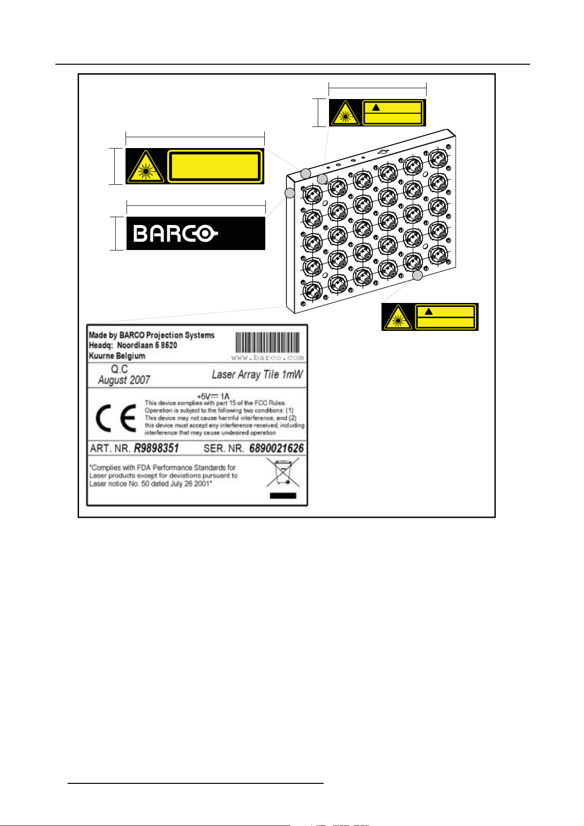
Stickers on the R9898351 (Class 2):
1. Laser Class Warning Sticker (Top / 50x13mm / Black + Warning Yellow)
2. 2x Laser Aperture Sticker (Front / 35x10 / Black + Warning Yellow)
3. Barco Patent Pending Sticker (Left / 50x12mm / Black + White)
4. Product Identification Sticker (Serial Number, ...)
50 mm
LASER RADIATION
13 mm
DO NOT STARE INTO THE BEAM
CLASS 2 LASER PRODUCT
50 mm
12 mm
Patent
Pending
10 mm
1
3
35 mm
CAUTION
!
LASER APERTURE ON THIS SIDE
2
2
CAUTION
!
LASER APERTURE ON THIS SIDE
Image 1-1
Safety Indications on the 1mW Laser Array (R9898351)
Following labels can be found on 3mW LDAT™:
4
R5976700 LASER DIODE ARRAY TOOL™ 21/01/2009
Page 9

1. Safety Instructions
Stickers on the R9898352 (Class 3R):
1. Laser Class Warning Sticker (Top / 50x13mm / Black + Warning Yellow)
2. 2x Laser Aperture Sticker (Front / 35x10 / Black + Warning Yellow)
3. Barco Patent Pending Sticker (Left / 50x12mm / Black + White)
4. Product Identification Sticker (Serial Number, ...)
50 mm
LASER RADIATION
13 mm
AVOID DIRECT EYE EXPOSURE
CLASS 3R LASER PRODUCT
50 mm
12 mm
Patent
Pending
10 mm
1
3
35 mm
CAUTION
!
LASER APERTURE ON THIS SIDE
2
2
CAUTION
!
LASER APERTURE ON THIS SIDE
Image 1-2
Safety Indications on the 3mW Laser Array (R9898352)
Safety Warning on the LDAT™
For the 1mW Laser Array (R9898351): LASER RADIATION, AVOID DIRECT EYE EXPOSURE WITH THE LASER BEAMS, CLASS
2 LASER PRODUCT!
On the3mW Laser Array (R9898352): LASER RADIATION, AVOID DIRECT EYE EXPOSURE WITH THE LASER BEAMS, CLASS
3R LASER PRODUCT!
Laser Aperture Location
The lasers are located on
Laser Safety Class for t
For the 1mW Laser Array (R9898351): The Laser Array is a Class 2 Laser Product.
For the 3mW Laser Array (R9898352): The Laser Array is a Class 3R Laser Product.
R5976700 LASER DIODE ARRAY TOOL™ 21/01/2009
the front side of the Laser Array.
he 1mW Laser Array (R9898351)
5
Page 10

1. Safety Instructions
6 R5976700 LASER DIODE ARRAY TOOL™ 21/01/2009
Page 11

2. Introduction
2. INTRODUCTION
2.1 LDAT™
WhyusetheLDAT™?
In multi-channel projection displays, externally generated test pattern grids are generally used
geometric (electrical) alignment of the many display channels. These test patterns are designed to represent the location of signifi-
cant landmarks that may be pre-calculated positions, according to the type of screen (flat, curved, front, rear, etc.), eye-points and
position of the projectors.
Many solutions exist to visualize the pre-calculated points to guide display alignment: one can mark "invisible" dots using UV-paint,
one can use a slide-projector to project these points, one can install small LED’s or fiber optic strands in the screen surface for
example. None of these solutions is ideal: they can’t be used on all types of screens, they require a complicated setup which may
include direct access to the screen surface, several are inaccurate and expensive to correct, and many can only be used in a dark
environment.
The ‘laser arrays’ provide a method and device for generating a test pattern grid for being used as reference for aligning display
channels without having the disadvantages of the solutions mentioned above.
The test pattern generator has a surface, each light source being moveably fixed on the surface and being adjustable such that a
direction of light emitted from each light source can be set for directing light from the light source onto the screen.
as references for mechanical and
2.2 Outline Lasers
Why use Outline Lasers?
Some Laser Light sources of the Laser Array are configured as Outline Lasers.
These Outline Lasers will mark the Outline corners of the desired projection area on the screen.
The Outline Lasers are the reference points for the mechanical alignment of the projectors.
This illustration shows a single display channel for a Dome Simulator Setup with a 5x6 Laser Array, 5 laser light sources are configured as Outline Laser, these mark 4 corners + 1 centre point of the Angular Field Of View
1
1. In a multi channel setup, each display channel will cover a specific field of the large screen (e.g. a dome simulator setup). This field is called the Angular Field Of View.
R5976700 LASER DIODE ARRAY TOOL™ 21/01/2009 7
Page 12

2. Introduction
Dome Simulator Setup
Projector for
Display Channel 1
Laser Array
Image 2-1
Outline Lasers
Outline
Lasers
Pattern projected
by Projector 1
Angular Field Of View
for Display Channel 1
2.3 Warp Lasers
Why use Warp Lasers?
The remaining laser light sources will be used as Warp Lasers.
These Warp Lasers will mark the geometric test pattern that is used for geometric (electrical) alignment of the projector.
This illustration shows a single display channel for a Dome Simulator Setup with a 5x6 Laser Array, 25 light sources are used to
mark the Warp Test Pattern.
8
R5976700 LASER DIODE ARRAY TOOL™ 21/01/2009
Page 13

Dome Simulator Setup
Laser Array
2. Introduction
Projector for
Display Channel 1
Warp
Lasers
Pattern projected
by Projector 1
Angular Field Of View
for Display Channel 1
Image 2-2
Lasers Outline
R5976700 LASER DIODE ARRAY TOOL™ 21/01/2009 9
Page 14

2. Introduction
10 R5976700 LASER DIODE ARRAY TOOL™ 21/01/2009
Page 15

3. CONTENT AND DIMENSIONS
Overview
• Content Laser LDAT™
• Dimensions
3.1 Content Laser LDAT™
Content
• Laser Array 6x5 Matrix
• Power Supply
• Adjustment Tube
3.2 Dimensions
LDAT™ Dimensions in mm (inch)
3. Content and Dimensions
Fixation Holes Ø 8.2mm (4x)
Image 3-1
Laser Array Dimensions
166.67 mm
6.58 inch
280 mm
11.02 inch
120 mm
4.72 inch
9.73 inch
8.58 inch
26.5 mm
1.04 inch
42 mm
1.65 inch
238 mm
218 mm
R5976700 LASER DIODE ARRAY TOOL™ 21/01/2009 11
Page 16

3. Content and Dimensions
12 R5976700 LASER DIODE ARRAY TOOL™ 21/01/2009
Page 17

4. CONNECTIONS
Overview
• Connections Overview
• LDAT™ Power Connection
4.1 Connections Overview
Connections Overview
The following table gives an overview of the connectors on the LDAT™:
Driver
Box
+5V
Outline
Warp
+5V +5V ON ON
Power In
Outline
Warp
External
Supply
4. Connections
Image 4-1
1
Power Switch Outline Lasers
2
Power Switch Warp Lasers
3
+5 VDC Power Supply Connection
4
+5 VDC Power Supply Connection for the Outline Lasers (for future use)
5
+5 VDC Power Supply Connection for the Warp Lasers (for future use)
Ta bl e 4 - 1
Laser Array Connections Overview
4.2 LDAT™ Power Connection
This connection is no longer needed when using an optional Driver Box, the Driver Box already contains a
Power Supply for 3 Laser Arrays.
AC Power Supply Connection
1. Connect the Power Supply to the DC Power Connection on the Top Side of the LDAT™.
1 5432
R5976700 LASER DIODE ARRAY TOOL™ 21/01/2009
13
Page 18

4. Connections
Image 4-2
Connect the Power Supply to the DC Power Connection on the Top Side of the LDAT™
Driver
Box
Image 4-3
Connect the Power Supply to the DC Power Connection on the Top Side of the LDAT ™
Outline
+5V
Warp
+5V +5V ON ON
Power In
2. Connect the Power Supply to the wall outlet
Outline
Warp
External
Supply
14
R5976700 LASER DIODE ARRAY TOOL™ 21/01/2009
Page 19

5. Operating the LDAT™
5. OPERATING THE LDAT™
Overview
• Introduction
• Operation
5.1 Introduction
Operating Modes of the LDAT™
The LDAT™ is operated using the switches located on top of the LDAT™ (These switches are protected by a switch cover).
5.2 Operation
WARNING: LASER RADIATION, AVOID DIRECT EYE EXPOSURE WITH THE LASER BEAMS, CLASS 2 or
CLASS 3R LASER PRODUCT!
Operation of the LDAT™
1. Loosen the 2 screws of the Cover on top of the LDAT™ and remove this cover.
Image 5-1
Loosen the 2 screw of the Cover on top of the LDAT™
The Power Switches are now accessible.
2. Use the switches to switch the Outline and/or Warp Lasers On/Off.
Driver
Box
Image 5-2
Use the switches to switch the Outline and/or Warp Lasers On/Off
Switching on the Outline Lasers will activate the 4 (+1 spare) laser pointers that indicate the outline corners of the non-distorted
projected image.
Switching on the Warp Lasers will activate the 25 laser pointers used for geometry alignment of the projector.
R5976700 LASER DIODE ARRAY TOOL™ 21/01/2009
Outline
+5V
Warp
+5V +5V ON ON
Power In
Outline
Warp
External
Supply
15
Page 20

5. Operating the LDAT™
16 R5976700 LASER DIODE ARRAY TOOL™ 21/01/2009
Page 21

6. ADJUSTING THE LDAT™
Overview
• Adjusting the position of the Laser Beam
WARNING: LASER RADIATION, AVOID DIRECT EYE EXPOSURE WITH THE LASER BEAMS, CLASS 2 or
CLASS 3R LASER PRODUCT!
WARNING: ALWAYS WEAR LASER SAFETY GLASSES WHEN ADJUSTING THE LASER ARRAY.
CAUTION: When adjusting the positions of the Laser Beams, wear protective clothing to avoid direct skin
exposure, e.g. by wearing gloves to protect the hands.
This will also avoid reflections of the Laser Beam on e.g. wristwatches and/or jewelry.
6.1 Adjusting the position of the Laser Beam
6. Adjusting the LDAT™
Necessary tools
• Laser Safety Glasses
• Protectiveclothingtocovertheskine.g. apairofgloves
• Adjustment Tube
How to adjust the Laser Beam Position?
1. Put the Adjustment Tube over the desired Laser Holder.
Image 6-1
Put the Adjustment Tube over the desired Laser Holder
2. Use the Adjustment Tube to move the Laser Holder to the desired position.
R5976700 LASER DIODE ARRAY TOOL™ 21/01/2009
17
Page 22

6. Adjusting the LDAT™
Image 6-2
Adjusting the position of the Laser Holder
Note: Due to the mechanical characteristics of the Laser Holders, repeat step 2 until the Laser Beam is in the perfect position.
3. Remove the Adjustment Tube.
Now the Laser beam will mark the desired point on the screen
4. Repeat step 1 to 3 to mark all the desired points on the screen.
18
R5976700 LASER DIODE ARRAY TOOL™ 21/01/2009
Page 23

INDEX
Index
A
Adjustment 17
LDAT™ 17
C
Connection 13
Power 13
LDAT™ 13
Connections 13
Overview 13
Content 11
LDAT™ 11
D
Dimensions 11
I
Installation 3
Instructions 3
Introduction 7, 15
L
Laser Aperture 5
Location 5
Laser Beam 17
Position 17
Adjusting 17
Laser Safety Class 5
1mW 5
LDAT™ 7, 11, 13, 15, 17
Adjustment 17
Content 11
Operate 15
Power 13
Connection 13
N
Notice on Safety 3
O
Operate 15
LDAT™ 15
Operation 3, 15
Instructions 3
Outline 7
Lasers 7
S
Safety 3, 5
Indications 3
Instructions 3
Warning 5
Service 3
Instructions 3
W
Warp 8
Lasers 8
R5976700 LASER DIODE ARRAY TOOL™ 21/01/2009
19
Page 24

Index
20 R5976700 LASER DIODE ARRAY TOOL™ 21/01/2009
Page 25

Revision Sheet
To :
Barco nv Avionics and Simulation Division
Noordlaan 5, B-8520 Kuurne
Phone: +32 56.36.82.11, Fax: +32 56.36.84.86
E-mail: info@barco.com, Web: www.barco.com
From:
Date:
Please correct the following points in this documentation (R5976700/01):
page wrong
correct
R5976700 LASER DIODE ARRAY TOOL™ 21/01/2009
 Loading...