

Page 1
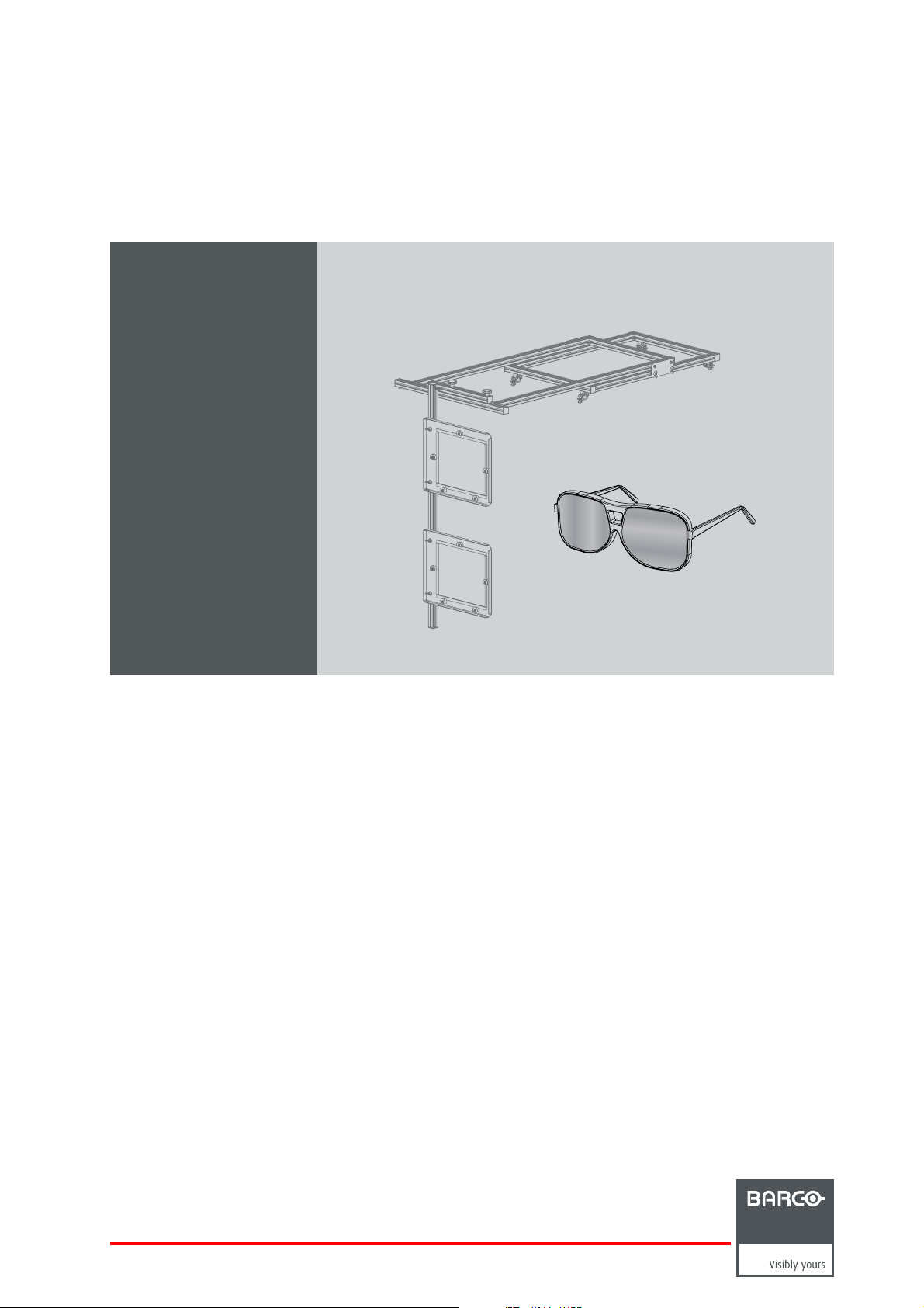
Polarization 3D Kit
R5905072/00
28/02/2011
Installation manual
For RLM W-se ries
R9864220
Page 2

Barco nv Events
Noordlaan 5, B-8520 Kuurne
Phone: +32 56.36.82.11
Fax: +32 56.36.88.24
E-mail: sales.events@barco.com
Visit us at the web: www.barco.com
Printed in Belgium
Page 3

Changes
Barco provides this manual ’as is’ without warranty of any kind, either expressed or implied, including but not limited to the implied warranties or merchantability and fitness for a particular purpose. Barco may make improvements and/or changes to the product(s) and/or the
program(s) described in this publication at any time without notice.
This publication could contain technical inaccuracies or typographical errors. Changes are periodically m ade to the information in this
publication; these changes are incorporated in new editions of this publication.
Copyright ©
All rights reserved. No part of this documen t may be copied, reproduced or translated. It shall not other
stored in a retrieval system without the prior written consent of Barco.
wise be recorded, transmitted or
Disposal Information
This equipment has required the extraction and use of natural resources for its production. It may contain hazardous substances for health
and environment. In order to av oid the dissemination of those substances in the environment and to diminish the pr essure on natural
resources, we encourage you to use the appropriate take-back systems. Those systems will reuse or recycle mos t of the materials of your
end of life equipment in a sound way.
The crossed-out wheeled bin symbol invites you to use those systems. If you need more information on the collection, reuse and recycling
systems, please contact your local or r egional waste administrator. You can also contact us for more information on the environmental
performances of our products.
Trademarks
Brand and product names mentioned in this manual may be trademark
All brand and product names mentioned in this manual serve as comments or examples and are not to be understood as advertising for
the products or their manufacturers.
s, registered trademarks or copyrights of their respective holders.
Page 4

Page 5

Table of contents
TABLE OF CONTENTS
1. Polarization 3D Kit ..... ................ ................ ................ ................ ................ ........... 3
1.1 Introduction .......................................................................................................................... 4
1.2 Installationprocess overview........................................................................................................ 6
2. Installation procedures................ ................ ................ ................ ................ ........... 7
2.1 Installationof the 3Dpolarizer assembly ........................................................................................... 8
2.2 Adjustment the 3D polarization filters...............................................................................................11
2.3 Cleaning the polarization filters .....................................................................................................13
2.4 Enabling/Disabling the 3D polarization filters....................................................................................... 14
R5905072 POLARIZATION 3D KIT 28/02/2011
1
Page 6

Table of contents
2 R5905072 POLARIZATION 3D KIT 28/02/2011
Page 7

1. Polarization 3D Kit
1. POLARIZATION 3D KIT
Purpose of the Polarization 3D Kit
The Polarization 3D Kit is exclusively designed for the Barco RLM W-series and can thus not be used on any other equipment.
Overview
• Introduction
• Installation process overview
R5905072 POLARIZATION 3D KIT 28/02/2011
3
Page 8

1. Polarization 3D Kit
1.1 Introduction
Function
The illusion of depth in a photograph, m ovie or other 2D image, is created by presenting a slightly different image to each eye. The
brain puts the two pictures together to form one 3D image.
The passive polarization 3D viewing system can be obtained with a dual projection setup.
In front of the lens of each projector, there’s a linear polarizer (reference 1, image 1-1). The polarization for the left eye is perpendicular to the one for the right eye.
The light emitted by the projectors is projected onto and reflected by a special screen (reference 2, image 1-1) that is coated to retain
the polarization.
The images are simultaneously projected on the screen, so they overlap, resulting in a blurry image. But since the spectators a re
wearing passive 3D g lasses (reference 3, image 1-1) with perpendicularly polarized lenses, they can see clear and well de fi ned 3D
images.
1
3
Image 1-1
Order info & content of the kit
When ordering the Polarization 3D Kit for RLM W-series, refer to article number R9864220.
The table below gives an ov erview of the content of the kit.
Article number Description
R5905072 This installation manual 1
R8760979 Frame assembly 1 image 1-2
B364356
B362188 Hammer nut 4 image 1-4
B362189
Clamp
Screw
Quantity
4 image 1-3
4 image 1-5
Image
2
4 R5905072 POLARIZATION 3D KIT 28/02/2011
Page 9

Image 1-2 Image 1-3 Image 1-4
1. Polarization 3D Kit
Image 1-5
R5905072 POLARIZATION 3D KIT 28/02/2011 5
Page 10

1. Polarization 3D Kit
1.2 Installation process overview
Installation from A to Z
1. S tack the two projectors. The two projectors must be stacked using the m ultifunctional frame, which is exclusively designed
for the Barco RLM W-series projectors. See the installation manual (R5905038) of the multifunctional frame (R9899700).
2. In stall the 3D polarizer assembly. The 3D polarizer assembly has to be mounted on the frame of the upper projector in the
dual stack. See "Installation of the 3D polarizer assembly", page 8 .
3. A lign the two stacked p rojectors. It is important that the p rojected images of both projectors coincide
the screen. S ee th e installation manual (R5905038) of the multifunctional frame (R9899700) to align the projectors using the
adjustments on the frames.
4. A pply 3D content to the stacked projectors. For that connect the 3D content for the left eye with the input port of the lower
projector and the 3D content for the right eye with the input port of the upper projector.
5. A djust the 3D polarization filters. For optimal 3D performance, the projected surface upon the polarization filters should be as
big as possible without loss of content. See "Adjustment the 3D polarization filters", page 11.
6. C lean the 3D polarization fi lters if necessary. See "Cleaning the polarization filters", page 13.
7. E nable/Disable the 3D polarization fi lters. F or 2D projection, the polarization filter has to be rem
jection lens. The 3D polarization assembly is designed to shift the filters away from the projection lens. See "Enabling/Disabling
the 3D polarization filters", page 14.
oved from the front of the pro-
with each other on
6
R5905072 POLARIZATION 3D KIT 28/02/2011
Page 11

2. INSTALLATION PROCEDURES
Overview
• Installation of the 3D polarizer assembly
• Adjustment the 3D polarization filters
• Cleaning the polarization filters
• Enabling/Disabling the 3D polarization filters
2. Installation procedures
R5905072 POLARIZATION 3D KIT 28/02/2011
7
Page 12

2. Installation procedures
2.1 Installation of the 3D polarizer assembly
How to install the 3D polarizer assembly?
1. P lace the 3D polarizer assembly on top of the two stacked projectors as illustrated (image 2-1). If necessary, adjust the position
of the clamps (reference 1, image 2-1) on the frame in the Y direction (reference 2, image 2-1). Release the sc rews (reference
3, im age 2-1) and slide the clamps as desired. Tighten the screws.
2. S ecure the 3D polarizer assembly on the upper multifunctional frame by locking the clamps (reference 1, image 2-1).
2
3
1
1
Image 2-1
3. Install the filter assembly with the filters in front of the projector lenses as illustrated (image 2-2). The upper profile of the filter
assembly has two guiding bolts (reference 4, image 2-2) which slide into the profile mounted o n top of the pro jector. Tighten the
two knobs (reference 5, image 2-2) on
top of the fi lter ass embly to secure the position of the polarization filters.
8
R5905072 POLARIZATION 3D KIT 28/02/2011
Page 13

2. Installation procedures
5
4
Image 2-2
4. Install the corner bracket (reference 6, image 2-3) upon the profile m ounted on top of the projector as illustrated. S lide the corner
bracket against the filterassemblybeforefastening. Usea4mmAllenwrenchtotightenthescrew(reference7,image 2-3) with
hammer nut (reference 8, image 2-3).
Note: This corner bracket functions as a reference for the filter assembly. In case the filter assembly was retracted for a 2D
projection it can easily be placed back in front o f the projection lens by sliding the assembly against the corner bracket.
5. P lace the plastic cap (reference 9, image 2-3) upon the profile.
R5905072 POLARIZATION 3D KIT 28/02/2011
9
Page 14

2. Installation procedures
9
7
6
8
Image 2-3
10 R5905072 POLARIZATION 3D KIT 28/02/2011
Page 15

2. Installation procedures
2.2 Adjustment the 3D polarization filters
Why adjusting the 3D polarization filters?
For optimal performance of the 3D polarization filters, the projected surface upon the polarization filters should be as big as possible
without loss of content. The design of the 3D polarization as sem bly makes it possible to adjust the position of the filters in the X , Y
and Z direction.
This procedure assumes that the projected images of both stacked projectors are already aligned.
Why adjusting the 3D polarization filters?
1. A djust the Y direction of the polarization filters until the center of the projected image matches the cen ter of the polarization filter.
Release the two knobs (reference 1, image 2-4) to reposition the assembly with polarization filt
the corner bracket (reference 2, image 2-4). Use a 4 mm Allen wrench to release the corner bracket.
Tip: Once the Y direction is correctly aligned, install the corner bracket against the assembly with polarization filters. This
corner bracket will function as a reference to reposition the polarization fi lters for 3D pro
for 2D projection.
1
ers. It may be necessary to release
jection after they were retraced
2
Image 2-4
2. A djust the height (Z direction) o f each polarization filter until the center of the projected image matches the center of the polarization filter. Release the two wing nuts (reference 3, image 2-5) to reposition the polarization filter. Tighten the wing nuts when
finished.
3
Image 2-5
3. A djust the X direction of the polarization filters, by sliding the upper frame aw ay or towards the projection lenses, until the projected surface upon the polarization filters is as big as possible without loss of content. Release the two wing screws (reference
4, image 2-6) at bo th sides of the assembly to reposition the assembly. Tighten the wing s crews when finished.
R5905072 POLARIZATION 3D KIT 28/02/2011
11
Page 16

2. Installation procedures
Image 2-6
4. Repeat step 1 to 3 until the projected surface upon the polarization filters is as big as possibl
4
e without los s of content.
12
R5905072 POLARIZATION 3D KIT 28/02/2011
Page 17

2. Installation procedures
2.3 Cleaning the polarization filters
When cleaning the polarization filters?
Only clean the polarization filters in case it is really necessary. This means in case dust is clearly visible upon the surface of the
polarization filters.
WARNING: ISOPROPANOL ALCOHOL (200–661–7).
Hazardous product. Irritating to eyes and skin. Always use in a well ventilated area. Vapors may cause drowsiness and dizziness. Avoid contact with skin and eyes. In case of con tact with the eyes, rinse immediately with
plenty of water and seek medical adv ise.
CAUTION: ISOPROPANOL A LCO HO L (200–661–7).
Hazardous product. Lightly flammable. Alw ays use in a well ventilated area. Keep away from sources of
ignitions. Do not smoke wh ile working with isopropanol. Exclusive keep in original container tightly closed
at a cool, well ventilated and fireproof storage space.
Necessary tools
• Compressed air.
TM
• Clean Toraysee
• Clean cotton cloth.
• Demineralized water.
• Isopropanol alcohol.
cloth.
How to clean the polarization filters?
1. Try to blow away the dust with compressed air.
2. Is all dust removed from the polarization filters?
If y es, stop this cleaning procedure.
If no, wipe off the dust of the polarization filters. Use for that a clean Toraysee
Caution: Always wipe in a single direction. Do not wipe back and forwards across the filter surface as this tends to grind dirt
Tip: Limit the n umber of wipe movements. This to protect the optical coating. It is better to wipe of the dust with one good
3. Is all dust removed from the polarization filters?
If y es, stop this cleaning procedure.
If no, wipe off the dust of the polarization filters first with a clean cotton cloth and demineralized water and than with a clean
Toraysee
Tip: Use isopropanol alcohol instead of demineralized water to remove fingerprints.
into the c oating.
wipe movemen t then with 10 soft wipe movements.
TM
cloth.
Do not leave cleaning cloth in either an open room or lab coat pocket, a s d oing so can contaminate the cloth.
If smears occur when cleaning lenses, replace t he cloth. Smears are the firstindicationofadirtycloth.
TM
cloth.
R5905072 POLARIZATION 3D KIT 28/02/2011 13
Page 18

2. Installation procedures
2.4 Enabling/Disabling the 3D polarization filters
2D and 3D projection
The design of the 3 D polarization assemb ly makes it possible to retract the filters from the lenses for 2D projection. The filters can
easily be placed back in their o riginal position by sliding the fi lter assembly against the reference bracket.
How to enable/disable the 3D polarization filters?
1. R elease the two knobs (reference 1, image 2-7) on top of the filter assembly.
2. S lide the filter assembly away from the lenses for 2D projection or slide the filter assembly against the reference bracket (reference 2, image 2- 7) for 3D projection.
3. Tighten the two knobs (reference 1, image 2-7) to secure the position of the filters.
3D
Image 2-7
2D
1
2
14 R5905072 POLARIZATION 3D KIT 28/02/2011
 Loading...