

Page 1
D320 Lite Digitizer
Installation Guidelines
R9851560
R5976471/02
1/2006
15/1
Page 2

Barco nv Events
Noordlaan 5, B-8520 Kuurne
Phone: +
32 56.36.89.70
Fax: +32 56.36.88.24
E-mail: sales.events@barco.com
Visit us at
the web: www.barco.com
Printed in Belgium
Page 3

Changes
Barco provides this manual ’as is’ without warranty of any kind, either expressed or implied, including but not
limited to the implied warranties or merchantability and fitness for a particular purpose. Barco may make improvements and/or changes to the product(s) and/or the program(s) described in this publication at any time
without notice.
This publication could contain technical inaccuracies or typographical errors. Changes are periodically made
to the information in this publication; these changes are incorporated in new editions of this publication.
Guarantee and Compensation
Barcoprovides aguarantee relatingto perfectmanufacturingas partof thelegally stipulatedtermsofguarantee.
Onreceipt,thepurchasermustimmediatelyinspect alldeliveredgoodsfordamageincurredduring transport,as
well as for material and manufacturing faultsBarcomustbeinformed immediately in writing of any complaints.
The period of guarantee begins on the date of transfer of risks, in the case of special systems and software
on the date of commissioning, at latest 30 days after the transfer of risks. In the event of justified not
complaint,Barcocan repairthefault orprovidea replacementat its owndiscretion withinan appropriateperiod.
If thismeasure provestobe impossibleorunsuccessful, thepurchasercan demandareduction inthepurchase
price or cancellation of the contract. All other claims, in particular those relating to compensat
indirect damage, and also damage attributed to the operation of software as well as to other services provided
byBarco,being acomponent ofthe systemor independentservice, willbe deemedinvalid providedthe damage
is not proven to be attributed to the absence of properties guaranteed in writing
negligence or part of Barco.
If the purchaseror a third party carriesoutmodifications or repairs ongoodsdelivered by Barco, or ifthegoods
are handled incorrectly, in particular if the systems are commissioned operated incorrectly or if, after the transfer of risks, the goods are subject to influences not agreed upon in the contract, all guarantee claims of the
purchaser will be rendered invalid. Not included in the guarantee coverage are system failures which are attributed to programs or special electronic circuitry provided by the purchaser, e.g. interfaces. Normal wear as
well as normal maintenance are not subject to the guarantee provided by Barco either.
or due to the intent or gross
ion for direct or
ice of
The environmentalconditions as wellasthe servicing and mainten
must be complied with by the customer.
ance regulationsspecified in thethismanual
Copyright ©
All rights reserved. No part of this document may be copied, reproduced or translated. It shall not otherwise
be recorded, transmitted or stored in a retrieval system without the prior written consent of Barco.
Trademarks
Brand and product names mentioned in this manual m ay be tra
of their respective holders. All brand and product names mentioned in this manual serve as comments or
examples and are not to be understood as advertising for the products or their manufactures.
demarks, registered trademarks or copyrights
Federal Communications Commissio n (FCC Statement)
This equipment has been tested and found to comply with the limits for a class A digital device, pursuant to
Part 15 of the FCC rules. These limits are designed to provide reasonable protection against harmful interference when the equipmentisoperated in a commercial environment. This equipment generates,uses, and can
radiate radio frequency energy and, if not installed and used in accordance with the instruction manual, may
cause harmful interference to radio communications. Operation of this equipment in a residential area may
cause harmful interference, in which case the user will be responsible for correcting any interference.
Page 4

Page 5

1. SAFETY
1.1 Important Safety Instructions
Instructions:
• Read these instructions.
• Keep these instructions.
• Heed all warnings.
• Follow all instructions.
• Do NOT submerge fully or partly in water or other liquids.
• Clean only with materials or chemicals that are inert, nonabrasive, noncorrosive and non-marking.
Consultthemanufacturer forfurther adviceshould any doubtsexist regardingany cleaning procedure.
• Do not block ventilation openings. Install in accordance with the manufacturers instructions.
• Do not install near any heat sources such as radiators, heat registers, stoves, or other apparat
(including amplifiers) that produce heat.
• Do not defeat the safety purpose of the polarized or grounding type plugs/sockets. If the provided
sockets /plugs aredamaged then replacementof thedefective partsmustbe undertakenimmediately.
• Protect the power/data cords from being walked on or pinched particularly at plugs, convenience receptacles, and the point where they exit from the apparatus. Replace damaged power/data cords
immediately.
• Only use attachments/accessories specified by the manufacturer.
• Disconnect the power to this apparatusduring lightning storms or provide suitable additional lightning
protection. Unplug this apparatus when unused for long period of time.
• Referall servicingto qualifiedservice technicians/personnel. Servicing isrequired whenthe apparatus
has been damaged in any way, such as power-supply cord or plug is damaged, the apparatus does
not operate normally, or has been dropped.
• Use only with systems or peripherals specified by the manufacturer, or sold with the apparatus. Use
caution during lifting/moving or transporting to avoid damage by possible tipping.
1. Safety
us
R5976471 D320 LITE DIGITIZER 15/11/2006
1
Page 6
1. Safety
1.2 Important Warnings
Important Warnings:
• Risk of electric shock:
Image 1-1
Risk of electrical shock
Risk of electric shock. Do not open. To reduce the risk of electric shock, do n
back). No user-serviceable parts inside. Refer servicing to qualified service personnel.
The lightning flash with an arrowhead within a triangle is intended to tell the user that parts inside this
product may cause a risk of electrical shock to persons.
The exclamation point within a triangle is intended to tell the user that important operating and/or
servicing instructions are included in the technical documentation for this equipment.
• Maximum ambient temperature:
The maximum recommended ambient temperature for this equipment is 40 °C.
• Flammable materials:
Keep flammable materials away from the installation (su ch as curtains)
into heat. The installation should be such that theamountofair flow required for safe operation of the
equipment is not compromised. Proper ventilation must be provided.
• This equipment MUST be earthed:
In order to protect against risk of electric shock, the installation should be properly grounded. Defeating thepurposeof the grounding typeplug will expose youtothe risk of electricshock. This apparatus
must be grounded (earthed) via the supplied 3 conductor AC power cord. (If the supplied power cord
is not the correct variant, consult your dealer.)
• Power system:
It is recommended to use a TN-S power distribution system (
arate neutral and grounding conductor) in o rder to avoid large ground currents loops due to voltage
differences in the neutral conductor. The total electrical installation should be protected by an appropriate rateddisconnect switch, circuitbreakers and G
shall bedoneaccording to the local electricalinstallation codes. In Europe specialattention should be
given to EN 60364, the standard for electrical installation of buildings. In Germany VDE 0100 should
be adhered to.
• Mains cords:
The power cords delivered with this system have special properties for safety. They are not user
serviceable. If the power cordsare damaged, replace only with new ones. Never try to repaira power
cord.
round FaultCurrent Interrupters. The installation
a power distribution system w ith a sep-
. A lot of energy is transferred
ot remove cover (or
2
R5976471 D320 LITE DIGITIZER 15/11/2006
Page 7

1. Safety
• Use of an extension cord:
If an extension cord is used with this product, make sure that the total of the ampere ratings on the
products plugged into the extension cord does not exceed the extension cord ampere rating. Also
make sure that the total of all products plugged into the wall outlet does not exceed 15 amperes.
• Cabinet openings:
Never push objects of any kind into this product through cabinet slots as they may touch dangerous
high voltage points or short out parts that could result in a risk of fire or electrical shock.
Never spill liquid of any kind on the product. Should any liquid or solid object fall into the cabinet,
unplug the set and have it checked by qualified service personnel before resuming operations.
R5976471 D320 LITE DIGITIZER 15/11/2006
3
Page 8

1. Safety
4 R5976471 D320 LITE DIGITIZER 15/11/2006
Page 9
2. Introduction
2. INTRODUCTION
2.1 General functionality
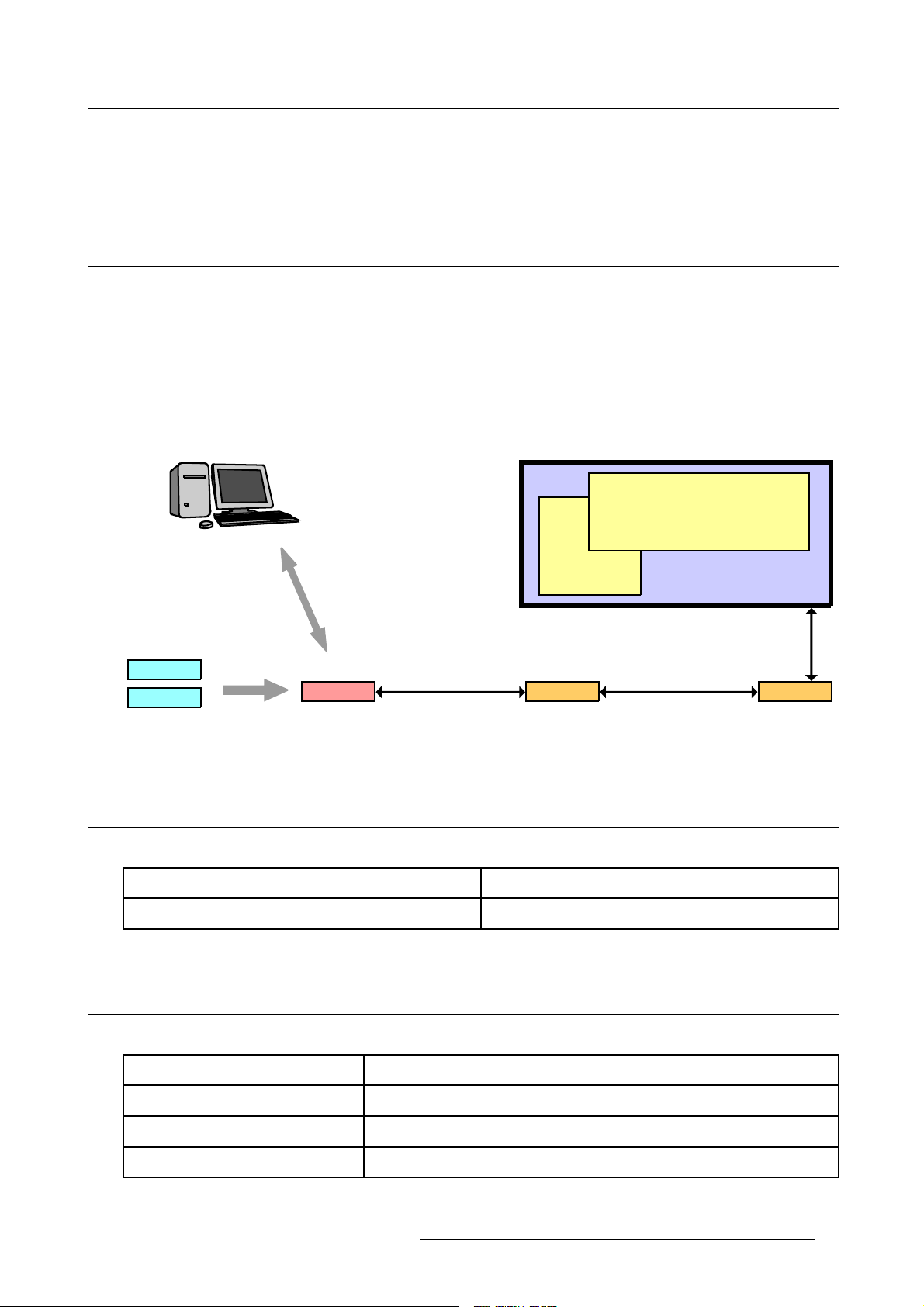
Overview
The D320Liteis a video processingdevice, designed to driveexclusively Barco LED walls. The D320 Lite
iscapable ofhandlingall standardoutput formatslikeSVGA, XGA,SXGA andUXGA onananalogRGBHV
and digital DVI output.
The D320 Lite Digitizerallowsyou to control up to 2sourceson one display. Seamless switch from source
to source or display sources together, overlay them, customize them. With analog and digital outputs
which allow for the control of displays, as well as built-in-controlsoftware,the D320 Lite gives you control
over everything from basic set-up to configuration and advanced feature control.
Display
SOURCE 1
SOURCE 2
Image 2-1
System overview
Analog Video
Digital Video
Control PC
Formated RGB Video Data /
D320Lite Fiberlink TX Fiberlink RX
Communication Data
2.2 Order info D320 Lite Digitizer
Order info:
Article No. Description
R9851560 D320 Lite Digitizer
Input 1
Input 2
Single / Multi
Mode Fiber
Video Data
Comm. Data
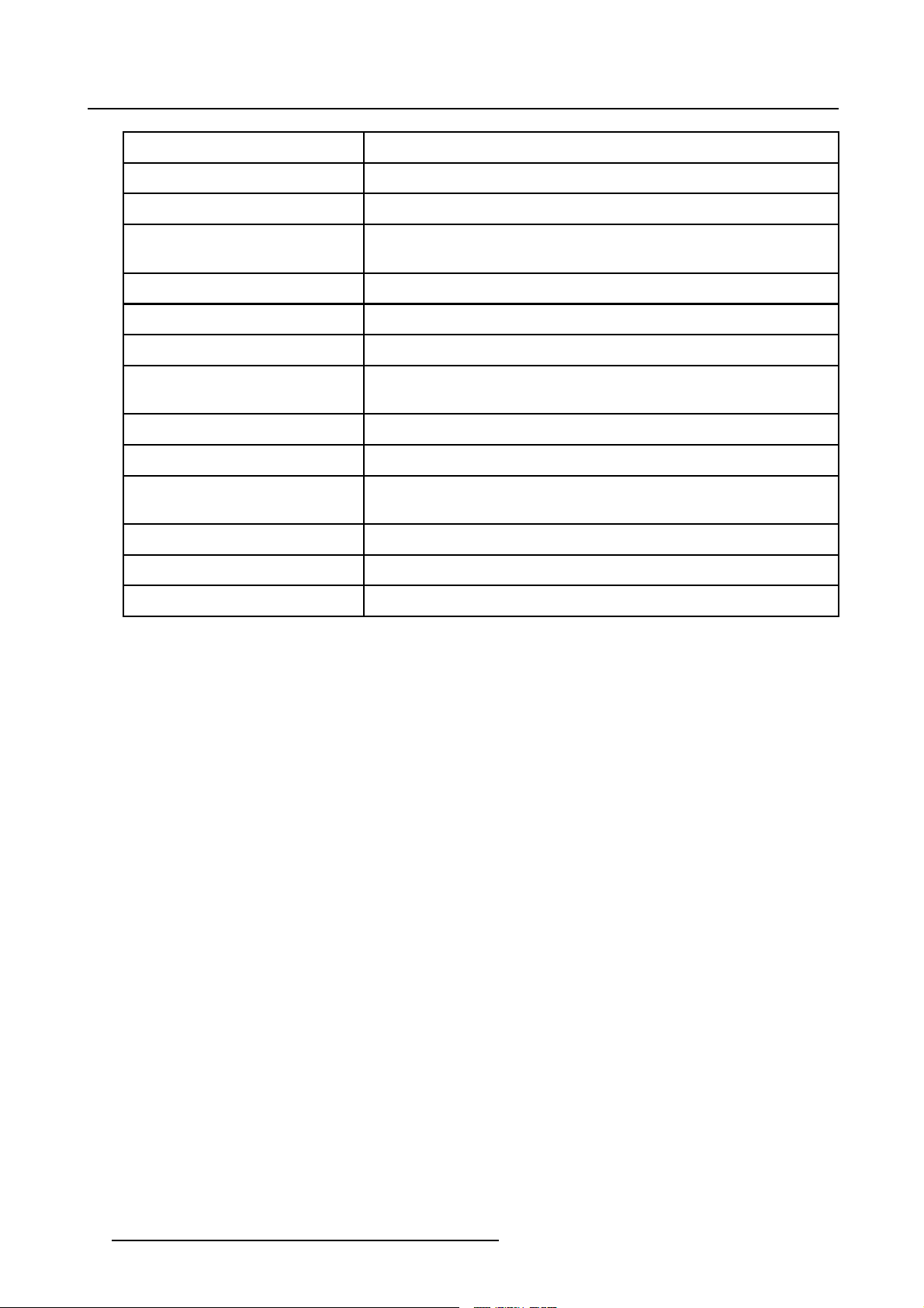
2.3 Technical summary
Summary
Type Value
Input slots
Compatibility
Output
R5976471 D320 LITE DIGITIZER 15/11/2006 5
2 input slots, front accessible, auto sensing and hot swappable
Barco LED walls
DVI-A, Barco LED protocol
Page 10
2. Introduction
Type Value
Scalability
Flexibility
Scaler 2 input channels [Data-Video]fully independent scalable to desired
Z-order control
Window Positioning
Connectors RS 232 [RJ 11] — Ethernet [RJ 45]
Effects Anamorphic imaging, Chroma keying [per input], Alpha keying [per
Ruggedness IP 10
Dimensions D320 Lite
Dimensions D320 Lite input
Units
Weight ±7kg
Operating Temperature 0ºC<>45ºC
Power consumption
no chaining, no stacking possible
User defined input
output resolution
Instant modification of Z-order control, for each output window
Intuitive positioning interface
input], Z-order control, Windowing/ View ports
486 x 482 x 53 (W x D x H)
41 x 181 x 103 (W x D x H)
130 Watt max at 85–264 Volt (50–60 Hertz)
6 R5976471 D320 LITE DIGITIZER 15/11/2006
Page 11

2.4 Dimensions of the D320 Lite Digitizer
1
0
5
Dimensions
2. Introduction
3
5
2
5
3
1
,
8
7
2
5
,
2
8
4
3
6
,
9
3
Image 2-2
2
1
,
6
4
4
4
8
6
,
2
3
2
3
,
5
6
4
R5976471 D320 LITE DIGITIZER 15/11/2006 7
Page 12

2. Introduction
8 R5976471 D320 LITE DIGITIZER 15/11/2006
Page 13

3. Physical Installation of the D320 Lite Digitizer
3. PHYSICAL INSTALLATION OF THE
D320 LITE DIGITIZER
3.1 Installation requirements for the D320 Lite digitizer
Requirements
• The D320 Lite digitizer should not be placed in a built-in installation or enclosure unless proper venti-
lation is provided.
• When using the unit in a multiunit rack assembly or closed assembly,the ambient temperature in
the assembly may not exceed the maximum rated ambient temperature of the digitizer. The installation should be such that the amount of air flow required for safe operation of the equipment is not
compromised.
• When buildingin the D320 Lite digitizerintoa rack with cover door, be aware that a spaceofminimum
85 mm is needed between the indicated reference and the cover door. This space is needed to guide
the input cables to the inputs.
side
85 mm
• The D320 Lite digitizer will require that air flows freely in vent holes. Blocking these holes will greatly
reduce the reliability of the unit and lead to the possibility of overheating.
• The D320 Lite Digitizer shouldoperatefrom an AC power source. The D320 Lite digitizer is equipped
with an auto-ranging power supply from 85 to 264 volt (50–60 Hertz).
• When installed in a rack, the mounting should be such that no hazardous condition is achieved due
to uneven mechanical loading.
• When the mains switch located on the back of the D320 Lite digitizer is not accessible due to rack
mounting, the socket outlet supplying the rack shall be installed near the equipment and be easily
accessible or a readily accessible disconnect device shall be incorporated in the fixed wiring. When
using a rack in an installation it is advisable to log the serial number of the device and to activate the
warranty figure by registering utilizing the included form.
• Do not place the D320 Lite digitizer on an
personal injury and serious damage to the digitizer.
• The data path between the D320 Lite digitizer and the LED display may not exceed five (5) meter.
unstable cart, stand or table. The device may fall, causing
R5976471 D320 LITE DIGITIZER 15/11/2006
9
Page 14

3. Physical Installation of the D320 Lite Digitizer
3.2 Connections
Rear panel inputs/outputs
A B
E F
Image 3-1
A LED-WALL OUTPUT
B Power Switch
C Power input
D Not used
E Retractable dust filter
F COM1 : RS232 input
G Not used
H Not used
I TCP-IP : Ethernet LAN connector
• A : LED-WALL OUTPUT
- LED wall out (Barco proprietary protoc ol).
• B : Power switch
- The power ON/OFF switch is provide on the rear side of the Digit
o
Switchpressedto1=theunitstarts.
o
Switch pressed to 0 = unit totally switched off.
• C : Power input
- Autoranging from 90 to 260 VAC / 130 Watt.
• D:Notused
• F : Retractable dust filter
- The fan intake grill of the Digitizer has a retractable dust filter. This filter can be retracted from the
back of the unit. Check the filter for good functionality on a regular basis. Never allow this filter to
become blocked up and never operate the unit without a good working air filter in place.
• G : COM1 : RS232 input
-Directmaster.
- RS232 in p ut port for communication links with local PC.
• H:Notused
• I : Not used
• J : TCP-IP : Ethernet LAN connector
- For future use.
C
izer.
D
G
H I
3.3 Removing and inserting a D320 Lite Digitizer input modul
There isno needto switchoff the D320Lite Digitizerto removeor insertan input module.
The input modules are hot swappable.
10 R5976471 D320 LITE DIGITIZER 15/11/2006
e
Page 15

3. Physical Installation of the D320 Lite Digitizer
How to remove an input module from the D320 Lite Digitizer
1. Push in the release button underneath the input module which you want to remove. At the same time
pull out the input module by the grip handle. (image 3-2)
2
1
Image 3-2
How to insert an input module into the D320 Lite Digitizer
1. Gently slide in the input module into a free input slot with the grip handle at the top.
2. Locking inthemodule bypushing the inputmodule completelyinto theD320Lite Digitizeruntil adefinite
click is audible.
CAUTION: Maximum two HDSDI input modules may be inserted in one D320 Lite Digi-
tizer.
R5976471 D320 LITE DIGITIZER 15/11/2006 11
Page 16

3. Physical Installation of the D320 Lite Digitizer
12 R5976471 D320 LITE DIGITIZER 15/11/2006
Page 17

4. Input modules
4. INPUT MODULES
Overview
• DVI input module
• SDI input module
• HDSDI input module
• CVBS / S-VID input module
• YUV / R G(s)B input module
• RGB analog input module
• Dummy input module
4.1 DVI input module
Technical info:
• Computer generated graphical source.
• DVI data in.
• 162 MHz pixel clock.
• Resolution from VGA to UXGA/60 Hz.
• DVI compliant.
• DVI loop through.
• Amber LED (upper LED on the front side) will be lit indicating module start up.
• When placed in an input slot the green LED (lower LED on the front side) will be lit indicating that
system acknowledges the module.
the
IN OUT
D320 DVI
Image 4-1
Image 4-2
Order info:
Article No. Description
R9850960 D320 Lite Digitizer DVI input module
R5976471 D320 LITE DIGITIZER 15/11/2006 13
Page 18

4. Input modules
4.2 SDI input module
Technical info:
• SDI data in.
• SDI loop through.
• 270Mbit/s transmission (SMPTE 259M-C).
• 525/625 interlaced.
• Coax (75 Ohm).
• Amber LED (upper LED on the front side) will be lit indicating recognition of film, either continuous or
intermittent film detection.
• When placed in an input slot the green LED (lower LED on the front side) will be lit indicating that the
system acknowledges the module.
IN OUT
D320 SDI
Image 4-3
Order info:
Article No. Description
R9850970
4.3 HDSDI input module
CAUTION: Maximum two HDSDI input modules may be inserted in one D320 Lite Digi-
tizer.
Image 4-4
D320 Lite Digitizer SDI input module
14 R5976471 D320 LITE DIGITIZER 15/11/2006
Page 19

4. Input modules
Technical info:
• HDSDI data in (SMPTE292M).
• HDSDI loop through (SMPTE292M).
• Coax (75 Ohm).
• When placed in an input slot the green LED (lower LED on the front side) will be lit indicating that the
system acknowledges the module.
• Supported HDSDI standards:
- Progressive:
o
1280x720/60/1:1/ (SMPTE 296M)
o
1280x720/59.94/1:1/ (SMPTE 296M)
o
1920x1080/30/1:1/ (SMPTE 274M)
o
1920x1080/29.97/1:1/ (SMPTE 274M)
o
1920x1080/25/1:1/ (SMPTE 274M)
o
1920x1080/24/1:1/ (SMPTE 274M)
o
1920x1080/23.98/1:1/ (SMPTE 274M)
- Interlaced:
o
1920x1035/60/2:1/ (SMPTE 260M)
o
1920x1035/59.94/2:1/ (SMPTE 260M)
o
1920x1080/60/2:1/ (SMPTE 274M)
o
1920x1080/59.94/2:1/ (SMPTE 274M)
o
1920x1080/50/2:1/ (SMPTE 274M)
o
1920/1080/50/2:1 (1250)/ (SMPTE 295M)
o
1920x1080/24/Segmented/ (SMPTE 274M)
o
1920x1080//23.98/Segmented/ (SMPTE 274M)
IN OUT
D320 HDSDI
Image 4-5
Image 4-6
Order info:
Article No. Description
R9850980
D320 Lite Digitizer HDSDI input module
R5976471 D320 LITE DIGITIZER 15/11/2006 15
Page 20

4. Input modules
4.4 CVBS / S-VID input module
Technical info:
•Video(BNC)
- CVBS : 1Vpp ±3dB (0,7V Video +0,3V Sync) 75 Oh m termination .
- BNC loop through connector.
• S-Video (4 pins DIN)
- Y : 1Vpp ±3dB (0,7V Video +0,3V Sync) 75 Ohm termination.
- U/V : 0,7Vpp ±3dB 100% color base, 75 Ohm termination.
- Chroma : Multi-Standard (PAL / SECAM / NTSC).
- 4 pins DIN loop through connector.
• Amber LED (upper LED on the front side) will be lit indicating recognition of film, either continuous or
intermittent film detection.
• When placed in an input slot the green LED (lower LED on the front side) will be lit indicating that the
system acknowledges the module.
• Supports MacroVision™.
IN OUT
Image 4-7
IN OUT
D320 CVBS/S-VID
Image 4-8
Order info:
Article No. Description
R9850920
D320 Lite Digitizer CVBS / S-VID input module
16 R5976471 D320 LITE DIGITIZER 15/11/2006
Page 21

4. Input modules
4.5 YUV / RG(s)B input module
Technical info:
• Component Video (BNC)
- R-Y : 0,7Vpp ±3dB 75 Ohm termination.
- Ys : 1Vpp ±3dB (0,7V Luma +0,3V Sync) 75 Ohm termination.
- B-Y : 0,7Vpp ±3dB 75 Ohm termination.
•RG(s)B(BNC)
- R : 0,7Vpp ±3dB 75 Ohm termination.
- G(s) : 1Vpp ±3dB (0,7Vpp G + 0,3Vpp Sync) 75 Ohm termination.
- B : 0,7Vpp ±3dB 75 Ohm termination.
• 3 BNC’s loop through connectors.
• Amber LED (upper LED on the front side) will be lit indicating recognition of film, either continuous or
intermittent film detection.
• When placed in an input slot the green LED (lower LED on the front side) will be lit indicating that the
system acknowledges the module.
• Supports MacroVision™.
IN OUT
D320 YUV/RGSB
Image 4-9
Image 4-10
Order info:
Article No. Description
R9850940
D320 Lite Digitizer YUV / RG(s)B input module
4.6 RGB analog input module
Technical info:
• Sub D15 connector for input and loop through.
• R, G, B, Hsync, Vsync : 0 to 1 Vpp ±3dB 75 Ohm termination.
• Black level : 300mV.
• Sync-tip : 0V
• Resolution : SXGA and UXGA version available.
• Amber LED (upper LED on the front side) will be lit indicating recognition of film, either continuous or
intermittent film detection.
• When placed in an input slot the green LED (lower LED on the front side) will be lit indicating that the
system acknowledges the module.
R5976471 D320 LITE DIGITIZER 15/11/2006
17
Page 22

4. Input modules
IN OUT
D320 RGB-AN
Image 4-11
Order info:
Article No. Description
Image 4-12
R9850950
R9851710
R9853120
4.7 Dummy input module
Technical info
• Dimensions : 103 x 181 x 41(W x D x H)
D320 DUMMY
Image 4-13
D320 Lite Digitizer RGB analog SXGA input
module
D320 Lite Digitizer RGB
analog UXGA input
module
D320 Lite Digitizer RGB analog input module
Image 4-14
Order info:
Article No. Description
R9850930 D320 Lite Digitizer dummy input module
18 R5976471 D320 LITE DIGITIZER 15/11/2006
Page 23

5. Cables and accessories for the D320 Lite Digitizer
5. CABLES AND ACCESSORIES FOR THE
D320 LITE DIGITIZER
5.1 Cables and accessories
List with available cables and accessories
Article No. Description Image
R326103
R3261115 Power cable with NEMA 5–15 plug. image 5-2
B5580491
Z3498421
R9827560
Z3499209
R9851210 Five meter data cable with DVI connectors. Used to connect the
R9851216
R9851219
Power cable with CEE7 plug.
Data cable with RJ12 connectors for RS232 connection between
local control PC and COM1 RS2 3 2 input p o rt of the master Digitizer.
Also used to connect th e COM2 or COM3 port with the COM1 port
of the following Digitizer.
RJ12–SUBD adapter.
Data cable with SUBD connectors for RS232 connection between
local control PC and COM1 RS232 input port of the master Digitize r.
One meter data cable with MDR connectors. Used to make a
connection between the LOOP OUT connector of the previous
Digitizer and the LOOP IN connector of the next Digitizer.
LED-WALL OUTPUT with an ILite display.
Five meter data cable with one DVI connector and one waterproof
MDR connector. Used to connect the LED-WALL OUTPUT with an
DLite display.
One meter data cable with one DVI connector and one MDR
connector. Used to connect the LED-WALL OUTPUT with a Fiberlink
Transmitter.
image 5-1
image 5-3
image 5-4
image 5-5
image 5-6
image 5-7
image 5-8
image 5-9
Image 5-1 Image 5-2 Image 5-3
R5976471 D320 LITE DIGITIZER 15/11/2006 19
Page 24

5. Cables and accessories for the D320 Lite Digitizer
Image 5-4 Image 5-5 Image 5-6
Image 5-7 Image 5-8 Image 5-9
20 R5976471 D320 LITE DIGITIZER 15/11/2006
Page 25

6. Configuration Schemes
6. CONFIGURATION SCHEMES
6.1 Stand alone configuration
Scheme
Local Control PC
with Control Software
Control
Data
RS232
Image 6-1
Video Inputs
12
LOOP IN
COM1
D320
TO DISPLAY
A D320 Lite is sufficient to drive one Barco LED wall wi
Display
Input 1
Video Data / Communication Data
th two different sources.
Input 2
How to set up a D320 Lite configuration
1. Connect the RS232 communication port of the local control PC with the COM1 RS232 input port of the
D320 Lite Digitizer.
2. Connect the LED-WALL OUTPUT from the D320 Lite D
3. Provide the available video sources to the D320 Lite input modules.
4. Con fig ure the D320 Lite Digitizer and theD isplay
with the control softwareinstalledon the local control
PC.
igitizer with the display.
R5976471 D320 LITE DIGITIZER 15/11/2006
21
Page 26

6. Configuration Schemes
22 R5976471 D320 LITE DIGITIZER 15/11/2006
Page 27

7. Control Software
7. CONTROL SOFTWARE
7.1 XLite Toolset
General introduction
The XLite Toolset (R9850042) is used to configure and control the D320 Lite Digitizer from basic set-up
to advanced features such as chroma keying, alpha blending or window positioning. Refer to the manual
(R5976380) for more information about the XLite Toolset.
7.2 Version Control Manager (VCM)
General introduction
TheVersion ControlManager (R9850044)is astand aloneprogram toupdate thesoftwareandfirmwareof
D320 LiteDigitizer. The softwareruns from CD-ROM andactslike a wizard. So noinstallation isrequired.
The software runs on a Windows platform. Refer to the manual (R5976407) for more information about
the Version Control Manager.
R5976471 D320 LITE DIGITIZER 15/11/2006
23
Page 28

7. Control Software
24 R5976471 D320 LITE DIGITIZER 15/11/2006
Page 29

8. Maintenance of the D320 Lite Digitizer
8. MAINTENANCE OF THE D320 LITE
DIGITIZER
8.1 Cleaning the dust filter
CAUTION: The fan intake grillof theD320 Lite Digitizerhas a retractable dustfilter which
must be checked for good functionality on regular basis. Never allow this filter to become blocked up.
How to clean the dust filter
1. Softly press down the lid of thedustfilter at the rear side of theD320Lite Digitizer and pull out thefilter.
(image 8-1)
2. Blow out all the dust from the filter and remove remaining dust with a dry cloth.
3. Place the clean dust filter back in the D320 Lite Digitizer.
Image 8-1
8.2 Cleaning the cabinet
CAUTION: Do not use liquid cleaners or aerosol cleaners. Never use strong solvents,
such as thinner or benzine, or abrasive cleaners, since these will damage the cabinet.
How to clean the cabinet
1. Unp lug the D320 Lite Digitiz er from the wall outlet before cleaning.
2. Clean the cabinet with a damp cloth. Stubborn
with mild detergent solution.
To keep the cabinet looking brand-new, periodically clean it with a soft dry cloth.
stains may be removed with a cloth lightly dampened
1
2
R5976471 D320 LITE DIGITIZER 15/11/2006 25
Page 30

8. Maintenance of the D320 Lite Digitizer
26 R5976471 D320 LITE DIGITIZER 15/11/2006
Page 31

9. OPTIONS
9.1 Overview
Order info:
Article No. Description
9. Options
R9851510
Climate Control Case for using the D320 Lite
Digitizer outdoor
R5976471 D320 LITE DIGITIZER 15/11/2006 27
 Loading...