

Page 1
XLite ToolSet
User Guide
R9850042
R5976380/14
3/2005
16/0
Page 2

Product revision
Software version: 2.6
Barco nv Events
Noordlaan 5, B-8520 Kuurne
Phone: +
Fax: +32 56.36.88.24
E-mail: events@barco.com
Visit us at
Printed in Belgium
32 56.36.89.70
the web: www.barco.com
Page 3

Software Licence Agreement
User agreement for XLite ToolSet Software
IMPORTANT: This Software Agreement is a legal agreement between the end user and the producer of the software product identified above, which includes computer software and associated media and printed materials,
and includes “online” or electronic documentation. By installing, copying, or otherwise using the SOFTWARE
PRODUCT, you agree to be bound by the terms of this Agreement.
The SOFTWARE PRODUCT is protected by copyright laws and international copyright treaties, as well as other
intellectual property laws and treaties.
Systems Software - You may install and use this SOFTWARE PRODUCT only in conjunction with other Barco
products where it is made for.
If you have acquired this software with the purchase of a product you may make a number of additional copies
of the computer software portion of the SOFTWARE PRODUCT only for authorized training off line for a Barco
System.
RIGHTS AND LIMITATIONS. You may not reverse engineer, decompile, or disassemble the SOFTWARE
PRODUCT.
NO LIABILITY FOR CONSEQUENTIAL DAMAGES To the maximum extent permitted by applicable law, in
no event shall the manufacturer or it’s suppliers be liable for any special, incidental, indirect, or consequential
damages whatsoever (including, without limitation, damages for loss of business profits, business interruption,
loss of business information, or any other pecuniary loss) arising out of the use of or inability to use the software
product, even if the manufacturer has been advised of the possibility of such damages.
Copyright ©
All rights reserved. No part of this document may be copied, reproduced or translated. It shall not otherwise
be recorded, transmitted or stored in a retrieval system without the prior
written consent of BARCO.
Trademarks
Brand and product names mentioned in this manual may be trademarks, registered trademarks or copyrights
of their respective holders. All brand and product names mentioned in this manual serve as comments or
examples and are not to be understood as advertising for the products or their manufactures.
Page 4

Page 5

Table of contents
TABLE OF CONTENTS
1. Introduction ..........................................................................................9
1.1 General introduction............................................................................................ 9
2. Installation.......................................................................................... 11
2.1 General Requirements........................................................................................11
2.2 Software installation........................................................................................... 11
2.3 Starting up......................................................................................................12
2.4 Troubleshooting Guide........................................................................................13
2.5 Updating XLite ToolSet........................................................................................13
2.6 Uninstalling XLite ToolSet.....................................................................................13
3. Logging On.........................................................................................15
3.1 Log on page....................................................................................................15
3.1.1 User Log on...............................................................................................15
3.1.2 Add user ..................................................................................................16
3.1.3 Delete user................................................................................................16
3.2 Start up Page...................................................................................................17
4. AutodetectPage ..................................................................................21
4.1 Autodetect page startup.......................................................................................21
4.2 RS232 Communication Settings .............................................................................22
4.3 Start Autodectection...........................................................................................23
4.4 Reload parameters from devices ............................................................................27
4.5 Serial Numbers ................................................................................................27
5. Wall PositioningPage ...........................................................................29
5.1 Start up .........................................................................................................29
5.2 Grid positioning ................................................................................................30
5.2.1 Selecting Grid positioning ...............................................................................30
5.2.2 Grid Dimensions..........................................................................................33
5.2.3 Define the Tile Linkage..................................................................................34
5.2.4 Wall Positioning for DLite, SLite, OLite and ILite walls...............................................34
5.2.5 Wall Positioning for MiPix ...............................................................................36
5.2.6 MiPix setup ...............................................................................................37
5.3 Manual Positioning ............................................................................................41
5.3.1 Selecting Manual positioning ...........................................................................41
5.3.2 Selection mode...........................................................................................43
5.3.3 Cutout coordinates for DLite/SLite/ILite/OLite.........................................................45
5.3.4 Cutout coordinates for MiPix............................................................................46
5.3.5 String functions for MiPiX ...............................................................................47
5.3.6 Export Cutout coordinates ..............................................................................48
5.4 MiPix Configurator.............................................................................................49
5.4.1 MiPix configurator overview.............................................................................50
5.4.2 Show preview stored design............................................................................51
5.4.3 Create new design .......................................................................................51
5.4.3.1 Start up..............................................................................................52
5.4.3.2 New block configuration ...........................................................................52
5.4.3.3 Outline in Grid.......................................................................................52
5.4.3.4 Auto fill...............................................................................................53
5.4.3.5 Advanced settings for auto fill.....................................................................54
5.4.3.6 Some typical examples where auto fill is very useful...........................................56
5.4.3.7 Manual fill............................................................................................57
5.4.3.8 Outline border On or Off ...........................................................................57
5.4.3.9 The design window.................................................................................58
5.4.3.10Save a design.......................................................................................59
5.4.4 Add blocks to a design ..................................................................................59
5.4.5 Edit existing design ......................................................................................61
5.4.5.1 Load a design.......................................................................................61
R5976380 XLITE TOOLSET 16/03/2005
1
Page 6

Table of contents
5.4.5.2 Save current version of the design ...............................................................62
5.4.5.3 Save current design under a new name .........................................................62
5.4.6 Block manipulations......................................................................................63
5.4.6.1 Selecting one block ................................................................................63
5.4.6.2 Selecting multiple blocks ..........................................................................63
5.4.6.3 Selecting a complete string........................................................................64
5.4.6.4 Deselect all blocks..................................................................................64
5.4.6.5 Moving a block ormultiple blocks.................................................................65
5.4.6.6 Delete selected blocks.............................................................................66
5.4.6.7 Swap two strings ...................................................................................66
5.4.6.8 Rotate selected blocks.............................................................................67
5.4.6.9 Auto rotation ........................................................................................68
5.4.6.10View wire direction of a string.....................................................................68
5.4.6.11Show rotation .......................................................................................69
5.4.6.12Simulate wire direction.............................................................................70
5.4.7 Delete a design...........................................................................................71
5.4.8 Zoom in - Zoom out......................................................................................71
5.4.9 Associate designs to devices ...........................................................................71
5.4.10 Internal pattern ...........................................................................................72
6. Stack Manager..................................................................................... 73
6.1 Basic principle of stacking ....................................................................................73
6.2 Restrictions on stacking.......................................................................................76
6.3 Before using the Stack manager.............................................................................76
6.4 Stack overview.................................................................................................76
6.5 Start up of the Stack Manager................................................................................78
6.6 Building the layout of the display.............................................................................78
6.7 Creating an extra display .....................................................................................80
6.8 Assigning screens to a display ...............................................................................82
6.8.1 Assigning singlescreens to a display..................................................................82
6.8.2 Assigning all screens to the same display.............................................................83
6.9 Removing a display............................................................................................83
6.10 Changing the properties of anexisting display .............................................................84
6.11 Layout screens.................................................................................................84
6.12 Changing the position of a display ...........................................................................85
6.13 Timings Overview masterDigitizer...........................................................................87
6.13.1 Output mode dependent timings .......................................................................87
6.13.2 How to start up an Timings Overview..................................................................88
6.13.3 Overview of the Timings for LED Wall output .........................................................88
6.13.4 Overview of the Timings for Digital output.............................................................89
6.13.5 Overview of the Timings for Analog output............................................................90
6.14 Zoom/pan in the screen representation pane...............................................................90
6.15 Reloading a configuration.....................................................................................90
6.16 Show or Hide Apply Settings .................................................................................90
6.16.1 Starting up Apply settings...............................................................................91
6.16.2 Reset windows after apply stack .......................................................................91
6.17 AdjustmentApply Level Settings.............................................................................91
7. System Configuration ...........................................................................95
7.1 Start up System configuration ................................................................................95
7.2 Input & DisplayConfiguration ................................................................................97
7.3 Windowing......................................................................................................99
7.3.1 General representation ..................................................................................99
7.3.2 Window Selection...................................................................................... 100
7.3.3 Changing a window name............................................................................. 100
7.3.4 Locking a window ...................................................................................... 101
7.3.5 Window, no scaling .................................................................................... 101
7.3.6 Moving Windows ....................................................................................... 102
7.3.7 Scaling Windows....................................................................................... 102
7.3.8 Making group changes to a window.................................................................. 103
2
R5976380 XLITE TOOLSET 16/03/2005
Page 7

Table of contents
7.3.9 Z-Order.................................................................................................. 104
7.3.10 Aspect Ratio ............................................................................................ 104
7.3.11 ViewPort................................................................................................. 105
7.3.11.1General............................................................................................ 105
7.3.11.2Creating a ViewPort.............................................................................. 106
7.3.11.3Making group changes........................................................................... 108
7.3.11.4Apply Viewport setting source A to sourceB.................................................. 108
7.3.12 Visibility setup of a source............................................................................. 108
7.3.13 Color Key ............................................................................................... 109
7.3.14 Alpha Blending ..........................................................................................111
7.3.15 Update All................................................................................................112
7.3.16 Settings...................................................................................................113
7.3.17 Preset Configurations...................................................................................113
7.3.17.1Saving a configuration ............................................................................113
7.3.17.2Loading a configuration, way 1...................................................................114
7.3.17.3Loading a configuration, way 2...................................................................115
7.3.17.4Removing a predefined configuration ...........................................................115
7.4 Work Space Resolution ......................................................................................116
7.5 Wall Settings ..................................................................................................117
7.5.1 Wall settings overview..................................................................................117
7.5.2 Gamma (non-linear color tracking)....................................................................118
7.5.2.1 Starting Gamma adjustment .....................................................................118
7.5.2.2 Gamma Curves overview.........................................................................118
7.6 Device Configuration ........................................................................................ 120
7.7 Configuration Manager...................................................................................... 122
7.7.1 Overview ofthe configuration manager.............................................................. 122
7.7.2 Saving a Configuration ................................................................................ 123
7.7.3 “Save as” a Configuration............................................................................. 124
7.7.4 Deleting a Configuration............................................................................... 125
7.7.5 Loading a Configuration............................................................................... 126
8. D310 Configuration..............................................................................129
8.1 D310 Configuration start up ................................................................................ 129
8.2 Settings ....................................................................................................... 129
8.2.1 Selected source ........................................................................................ 130
8.2.2 Input Settings........................................................................................... 130
8.2.2.1 Starting up the Input Settings ................................................................... 130
8.2.2.2 Image Processing ................................................................................ 131
8.2.2.3 Video Equalizing.................................................................................. 132
8.2.2.4 Dynamic Image Stabilizer ....................................................................... 132
8.2.2.5 Color Matrix ....................................................................................... 132
8.2.3 Digitizer Settings ....................................................................................... 132
8.2.3.1 Digitizer Settings Start up........................................................................ 132
8.2.3.2 Advanced Settings ............................................................................... 133
8.2.3.3 General Advanced Settings ..................................................................... 134
8.3 Device Properties Windowing Option...................................................................... 134
8.4 Device Properties Digitizer.................................................................................. 134
9. D320 Configuration..............................................................................135
9.1 D320 Configuration start up ................................................................................ 135
9.2 Digitizer Settings............................................................................................. 135
9.2.1 OperationalMode ...................................................................................... 136
9.2.2 Sync Generator......................................................................................... 136
9.2.2.1 How to start up.................................................................................... 136
9.2.2.2 Timings of Sync Generator ...................................................................... 138
9.2.2.3 The Timing Wizard ............................................................................... 139
9.2.2.4 Finishing the Timings of the Sync Generator.................................................. 141
10.D320PLConfiguration..........................................................................143
10.1 D320PL Configuration start up............................................................................. 143
R5976380 XLITE TOOLSET 16/03/2005
3
Page 8

Table of contents
10.2 Digitizer Settings............................................................................................. 144
10.2.1 Operational Mode ...................................................................................... 144
10.2.2 Output Selection........................................................................................ 146
10.2.3 Monitor Preview of an image on a LED wall ........................................................ 147
10.2.3.1Introduction and Start up ........................................................................ 147
10.2.3.2Moving the monitor preview in the active area ................................................ 147
10.2.3.3Settings............................................................................................ 148
10.2.4 Timings.................................................................................................. 149
10.2.4.1Using predefined timings for digital or analog output......................................... 149
10.2.4.2Using the advanced timing settings for digital or analog output ............................. 150
10.2.4.3Timings of Sync Generator for Digital or Analog output...................................... 152
10.2.4.4Timings of Display Interface for Digital or Analog output..................................... 154
10.2.4.5Lock mode for Barco LED Wall output ......................................................... 155
10.2.4.6Timings of Sync Generator for Barco LED Wall output selected ............................ 156
10.2.5 Pattern Generation..................................................................................... 157
10.2.5.1Overview and activation ......................................................................... 157
10.2.5.2Test pattern set up................................................................................ 157
11.D320L Configuration............................................................................159
11.1 D320L Configuration start up............................................................................... 159
11.2 Digitizer Settings............................................................................................. 160
11.2.1 Operational Mode ...................................................................................... 160
11.2.2 Sync Generator......................................................................................... 161
11.2.2.1How to start up.................................................................................... 161
11.2.2.2Timings of Sync Generator ...................................................................... 162
11.2.2.3The Timing Wizard ............................................................................... 163
11.2.2.4Lock mode ........................................................................................ 163
11.2.3 Monitor preview of an imageon the LED wall....................................................... 165
11.2.3.1Introduction and Start up ........................................................................ 165
11.2.3.2Moving the monitor preview in the active area................................................ 165
11.2.3.3Settings............................................................................................ 166
11.2.4 Pattern Generator...................................................................................... 167
11.2.4.1Overview and activation ......................................................................... 167
11.2.4.2Test pattern set up................................................................................ 168
12.D320Lite Configuration........................................................................171
12.1 D320Lite Configuration start up ............................................................................ 171
12.2 OperationalMode............................................................................................ 172
12.3 Sync Generator .............................................................................................. 172
12.3.1 How to start up ......................................................................................... 172
12.3.2 Timings of Sync Generator............................................................................ 174
12.3.3 The Timing Wizard..................................................................................... 175
12.3.4 Lock mode .............................................................................................. 175
12.4 Monitor preview of an image on the LED wall ............................................................ 176
12.4.1 Introduction and Start up .............................................................................. 176
12.4.2 Moving the monitor preview in the active area...................................................... 177
12.4.3 Settings.................................................................................................. 178
12.5 Pattern Generator............................................................................................ 179
12.5.1 Overview and activation............................................................................... 179
12.5.2 Test pattern set up ..................................................................................... 179
13.Input Slots for D320 series....................................................................181
13.1 General info .................................................................................................. 181
13.2 Input D320 DVI-D............................................................................................ 182
13.2.1 Settings start up ........................................................................................ 182
13.2.2 Image Processing ...................................................................................... 182
13.3 Input D320 YUV/RG(s)B .................................................................................... 183
13.3.1 Settings start up ........................................................................................ 183
13.3.2 Image Processing ...................................................................................... 184
13.3.3 Input Gain Equalizing.................................................................................. 185
4
R5976380 XLITE TOOLSET 16/03/2005
Page 9

Table of contents
13.3.4 Dynamic Image Stabilizer (DIS) ...................................................................... 186
13.4 Input D320 SDI............................................................................................... 186
13.4.1 Settings start up ........................................................................................ 186
13.4.2 Image Processing ...................................................................................... 187
13.4.3 Dynamic Image Stabilizer (DIS) ...................................................................... 187
13.5 Input D320 HDSDI........................................................................................... 188
13.5.1 Settings start up ........................................................................................ 188
13.5.2 Image Processing ...................................................................................... 188
13.6 Input D320 CVBS/S-Vid..................................................................................... 189
13.6.1 Settings start up ........................................................................................ 189
13.6.2 Image Processing ...................................................................................... 190
13.6.3 Input Gain Equalizing.................................................................................. 192
13.6.4 Dynamic Image Stabilizer (DIS) ...................................................................... 193
13.7 Input D320 RGB analog..................................................................................... 193
13.7.1 Settings start up ........................................................................................ 193
13.7.2 Image Processing ...................................................................................... 194
13.7.3 Resolution Settings .................................................................................... 195
13.7.4 RGB Contrast........................................................................................... 195
13.7.5 RGB Brightness ........................................................................................ 196
13.8 Input D320 RGB analog (UXGA)........................................................................... 196
13.8.1 Settings start up ........................................................................................ 196
13.8.2 Image Processing ...................................................................................... 196
13.8.3 Resolution Settings .................................................................................... 197
13.8.4 RGB Contrast........................................................................................... 198
13.8.5 RGB Brightness ........................................................................................ 198
13.9 Input D320 RGB UXGA 2................................................................................... 199
13.9.1 Settings start up ........................................................................................ 199
13.9.2 Image Processing ...................................................................................... 199
13.9.3 Black balance........................................................................................... 201
13.9.4 White balance .......................................................................................... 201
13.9.5 AMD System............................................................................................ 201
13.9.5.1Auto Measurement ............................................................................... 201
13.9.5.2Manual file selection ............................................................................. 201
13.9.5.3Add new item to list .............................................................................. 202
13.9.5.4Remove item from list............................................................................ 203
13.9.5.5Remove all items from the list................................................................... 203
13.9.5.6Best ADC setting ................................................................................. 204
13.9.5.7Default list ......................................................................................... 205
13.9.5.8Total pixels per line............................................................................... 205
14.FiberLink Configuration .......................................................................207
14.1 Start up ....................................................................................................... 207
14.2 FiberLink Selection .......................................................................................... 208
14.3 Pattern Generator............................................................................................ 208
14.4 Reconstruction Filter ........................................................................................ 208
14.5 Key Reference............................................................................................... 209
14.6 LED Wall Power.............................................................................................. 209
14.7 Device Properties FiberLink ................................................................................ 209
15.FiberLink 2 configuration .....................................................................211
15.1 Start up ........................................................................................................211
15.2 FiberLink 2 Selection ........................................................................................ 212
15.3 Pattern Generator............................................................................................ 212
15.4 LED Wall Power.............................................................................................. 212
15.5 Device Properties FiberLink ................................................................................ 212
16.DLiteDisplay Configuration..................................................................215
16.1 Configuration Start up....................................................................................... 215
16.2 Screen Settings.............................................................................................. 216
16.2.1 Overview................................................................................................ 216
R5976380 XLITE TOOLSET 16/03/2005
5
Page 10

Table of contents
16.2.2 Tile Settings............................................................................................. 217
17.ILiteDisplay Configuration ...................................................................221
17.1 Configuration Start up....................................................................................... 221
17.2 Screen settings .............................................................................................. 222
17.2.1 Overview................................................................................................ 222
17.2.2 OSD functions for ILite 6/8/10/12..................................................................... 224
17.2.2.1OSD functions for ILite 6/8/10/12............................................................... 224
17.2.2.2Overview OSD Screens ......................................................................... 225
17.2.2.3OSD control....................................................................................... 227
17.2.3 OSD function for ILite 3................................................................................ 227
17.2.4 Tile Settings............................................................................................. 230
18.ILiteMD Display Configuration ..............................................................233
18.1 Configuration Start up....................................................................................... 233
18.2 Screen Settings.............................................................................................. 234
18.2.1 Overview................................................................................................ 234
18.2.2 OSD functions.......................................................................................... 236
18.2.3 Tile Settings............................................................................................. 237
19.SLiteDisplay Configuration ..................................................................241
19.1 Configuration Start up....................................................................................... 241
19.2 Screen settings .............................................................................................. 242
19.2.1 Overview................................................................................................ 242
19.2.2 OSD functions.......................................................................................... 243
19.2.3 Tile Settings............................................................................................. 247
20.OLiteDisplay Configuration ................................................... ...............251
20.1 Configuration Start up....................................................................................... 251
20.2 Screen settings .............................................................................................. 252
20.2.1 Overview................................................................................................ 252
20.2.2 OSD functions.......................................................................................... 254
20.2.3 Tile Settings............................................................................................. 255
20.2.4 View properties modules .............................................................................. 257
21.MiPix Display Configuration..................................................................259
21.1 Configuration Start up....................................................................................... 259
21.2 Screen settings .............................................................................................. 260
21.2.1 Overview................................................................................................ 260
21.2.2 Tile Settings............................................................................................. 261
22.AEC Configuration..............................................................................265
22.1 Start up ....................................................................................................... 265
22.2 AEC settings ................................................................................................. 266
22.3 Device Properties AEC...................................................................................... 266
23.Maintenance Page...............................................................................267
23.1 Start up ....................................................................................................... 267
23.2 Update Software............................................................................................. 267
23.2.1 Update Software Start up ............................................................................. 267
23.2.2 ILite Display............................................................................................. 269
23.2.3 DLite Display ........................................................................................... 270
23.2.4 OLite Display ........................................................................................... 271
23.2.5 SLite Display............................................................................................ 272
23.2.6 Windowing Option...................................................................................... 273
23.2.7 FiberLink Option........................................................................................ 274
23.2.8 FiberLink2 update software ........................................................................... 275
23.2.9 AEC...................................................................................................... 276
23.3 Color Calibration............................................................................................. 276
23.3.1 Color Calibration for DLite, SLite, ILite (embedded soft < 2.05) except ILite3 and MiPiX...... 276
23.3.2 Color Calibration for ILite and OLite.................................................................. 280
6
R5976380 XLITE TOOLSET 16/03/2005
Page 11

Table of contents
23.3.2.1Start up............................................................................................ 280
23.3.2.2Preview set up of the diagram .................................................................. 282
23.3.2.3Changing a color point........................................................................... 283
23.3.2.4Color temperature (white point)................................................................. 284
23.3.2.5Loading the default Targets...................................................................... 286
23.3.2.6Calibration levels ................................................................................. 286
23.3.2.7Run mode LED wall .............................................................................. 287
23.3.2.8Start up the calibration procedure .............................................................. 288
24.Monitoring Page .................................................................................289
24.1 Start up of the Monitoring Page ............................................................................ 289
24.2 MonitoringStatus ............................................................................................ 289
24.3 Monitor Settings.............................................................................................. 290
24.3.1 Temperature Control Set up........................................................................... 290
24.3.2 Ambient Environment Control set up for Monitoring................................................ 290
24.3.2.1Monitor Settings .................................................................................. 290
24.3.2.2AEC Settings...................................................................................... 291
24.3.3 Monitoring set up....................................................................................... 292
24.4 Monitor Reminder Message ................................................................................ 292
24.5 Log Data...................................................................................................... 293
24.5.1 Diagnostic Check ...................................................................................... 293
24.5.2 Temperature History ................................................................................... 293
24.5.3 ContrastHistory ........................................................................................ 294
24.5.4 AEC Light History ...................................................................................... 295
Index ...................................................................................................297
R5976380 XLITE TOOLSET 16/03/2005 7
Page 12

Table of contents
8 R5976380 XLITE TOOLSET 16/03/2005
Page 13
1. Introduction
1. INTRODUCTION
1.1 General introduction
Overview
The display and configuration ‘’Xlite ToolSet Software’’ is designed preliminary as a user interface (GUI).
This software works in combination with the existing :
• Barco Digitizers D310
• Barco Digitizers D320 series
• Barco DLite, ILite and SLite Displays
• Barco MiPix Displays
• FiberLink
• AEC
• Barco projectors (D320PL)
Windows is the operating environment (Windows NT/2000) for the software.
The "Xlite ToolSet Software" is a DHTML based application and runs out of Microsoft Internet Explorer 5.
or later. The software is divided in six main work sections, after logging on.
The Control Software can be used to control and configure of Barco ILite Systems, SLite Systems, DLite
Systems or MiPix systems, either locally or via a network. (LAN, WAN or internet).
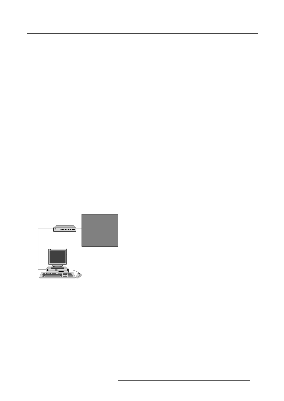
Connection Configurations
When connected through a serial RS232 connection.
RS232
Image 1-1
Configuration with client & server on one PC
Connection configurations can be achieved directly from a PC to a Digitizer or via a PC connected to an
local Server on a local area network (LAN). With the Digitizer connected to the local server.
Digitizer
310/320
PC
D/ILite Display
Client +
WebServer +
Local Server
5
R5976380 XLITE TOOLSET 16/03/2005
9
Page 14
1. Introduction
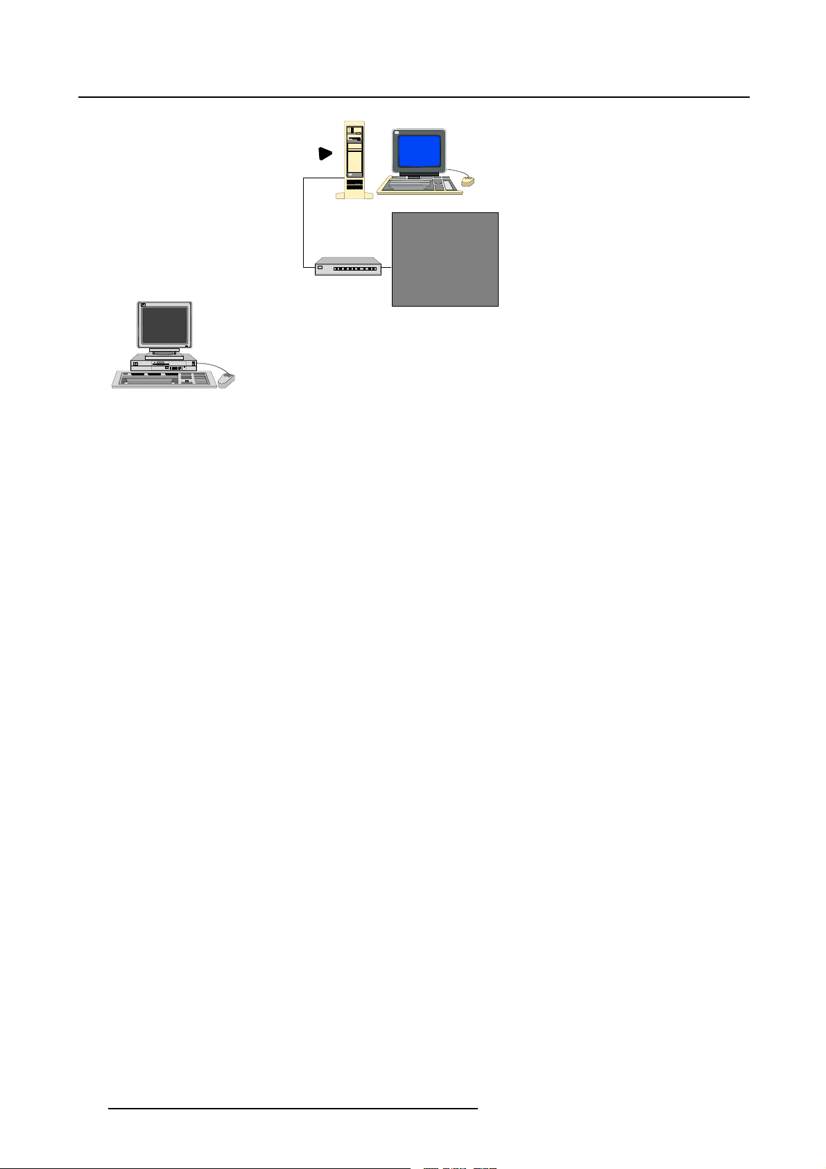
TCP/IP
Client
Image 1-2
Configuration with client & server on a different PC.
Web Server +
Local Server
RS232
Digitizer
310/320
D/ILite Display
10 R5976380 XLITE TOOLSET 16/03/2005
Page 15

2. Installation
2. INSTALLATION
Overview
• General Requirements
• Software installation
•Startingup
• Troubleshooting Guide
• Updating XLite ToolSet
• Uninstalling XLite ToolSet
2.1 General Requirements
Before you begin
It assumes you are familiar with the Windows operating system at your site.
The CD-ROM in your package contains a Windows-based installation program. You can install the software from the CD-ROM.
System requirements
A minimum configuration of a Pentium II processor, 160 MHz and 128 MB of RAM.
At least 50 MB of disk space. A CD-ROM drive.
The operating system required is a 32 bit Windows version:
• Windows NT 4.0. with service pack 4.0
• Windows 2000
•WindowsXP
Microsoft Internet Explorer 5.5 or higher
The screen resolution of the software is 1024*768 for a good working environment.
2.2 Software installation
To install
The process of installing your software involves the following basic steps:
1. Insert the CD-ROM in the CD-ROM drive.
2. Is the AutoPlay active on your PC.
If yes, continue with step 7.
If no, from within the Windows environment go to the Start Menu. Choose Run... from the menu and
proceed with the next steps.
3. Open windows explorer.
4. Select the CD-ROM Drive.
5. Double click ‘setup.exe’ file.
6. Press ‘OK’ to run the installation.
7. For a new installation select ’Typical’.
With ’Typical’, everything necessary to run the program will be installed (Tomcat webserver, Java environment variables and plug ins for the applets).
R5976380 XLITE TOOLSET 16/03/2005
11
Page 16

2. Installation
With ’Custom’ you have the choice to install only the Xlite part or only the Java part.
8. Press ‘Enter’ to execute the installation program.
9. Complete installation is automatic.
’XLite ToolSet’ item will be added to the program list.
Check
Some settings of the PC must be checked before launching the software:
1. Check if the Java Virtual machine (VM) is enabled on the PC.
2. Open your Internet Explorer.
Select Tools → Internet Options → Temporary Internet Files → Settings.
3. Check ’Every visit to the page’ and press OK. (image 2-1)
Image 2-1
Internet options Settings
2.3 Starting up
Start up
To start up the XLite ToolSet software, the following steps are involved:
1. Go to the Start menu, select Programs.
2. Drag your mouse to the right and select XLite ToolSet v2. Drag further to the right and select XLite
ToolSet.(image2-2)
This action starts first the service launcher whic
- Tomcat Webserver
-Driver
- Admin engine
- sysid
And it start then XLite ToolSet itself.
Image 2-2
Start up of XLite ToolSet
h contains the following processes :
12 R5976380 XLITE TOOLSET 16/03/2005
Page 17
2. Installation
2.4 Troubleshooting Guide
Overview
A troubleshooting guide with the most frequently discovered problems is online available on the CD-ROM.
2.5 Updating XLite ToolSet
Wheretofindupdate
From time to time, updates or new versions of the XLite ToolSet are released in the PartnerZone on the
internet.
As a registered partner, you can download these updates.
If you are not yet a partner, you can register yourself as a new partner. For more information, surf to
h
ttp://events.barco.com and follow the link Services -> Secure Zone.
Once you have access to the Partner Zone, download the latest version of the XLite ToolSet and save it
to your local hard disk. The file is a self-extracting zip file.
How to update
1. Browse in Windows Explorer to the directory where the zip file was saved.
2. Extract the zip file in the desired directory.
3. Go to the directory in which the zip file is extracted and double click on setup.exe.
The setup file will automatically update the current version of the XLite ToolS
If you have already installed the update, a notice will be shown asking you if you want to uninstall the
update. Uninstalling the update will make the current installation corrupt.
You cannot uninstall an update to return to the previous version. If you uninstall an
update, the files are removed and the XLite ToolSet will no longer work properly.
If you want to go back to an older version, re-install the original versi
CD, delivered with the digitizer), and install the updated version over it.
2.6 Uninstalling XLite ToolSet
If youhave also installed an update for XLiteToolSet,this should be removed first before
uninstalling XLite ToolSet itself.
et.
on (the one on the
How to uninstall
1. Open the Control Panel of your windows (Start → Settings → Control Panel).
2. Select XLite ToolSet from the list and click on the Change/Remove button.
The uninstall procedure for XLite ToolSet will start.
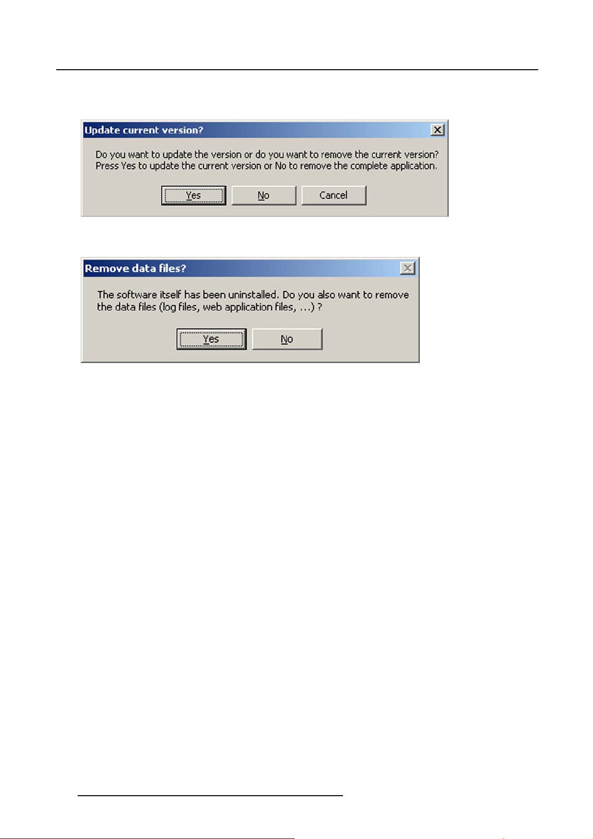
3. The uninstall wizard asks for confirmation. (image 2-3)
4. Click No to remove completely.
5. Do you want to remove the data files too? Data files are the user files, preset files, configuration, etc.
R5976380 XLITE TOOLSET 16/03/2005
13
Page 18
2. Installation
If yes, click on Yes. Every thing will be deleted. (image 2-4)
If no, click on No. XLite ToolSet will be able to work on the same configuration when reinstalled later.
Image 2-3
Uninstall confirmation
Image 2-4
Data files removal during uninstall
14 R5976380 XLITE TOOLSET 16/03/2005
Page 19
3. LOGGING ON
Overview
• Log on page
•StartupPage
3.1 Log on page
Overview
• User Log on
• Add user
•Deleteuser
3.1.1 User Log on
Overview
3. Logging On
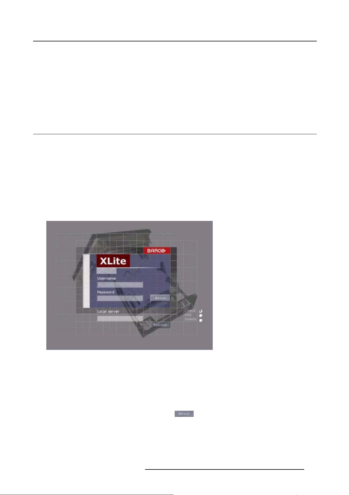
The login page is the first page of the GUI after starting up the software.
Image 3-1
Log on page
There are 3 actions you can do on this page:
•check
•add
• delete
This specified with the 3 radio buttons (right corner of the login screen).
When user name and password are filled in, w
ith
thebuttonbothboxescanbecleared.
Check
1. Check the check radio button. (image 3-2)
2. Fill in a user name and password.
R5976380 XLITE TOOLSET 16/03/2005
15
Page 20
3. Logging On
3. Click on submit to login.
The software validates the entry.
Image 3-2
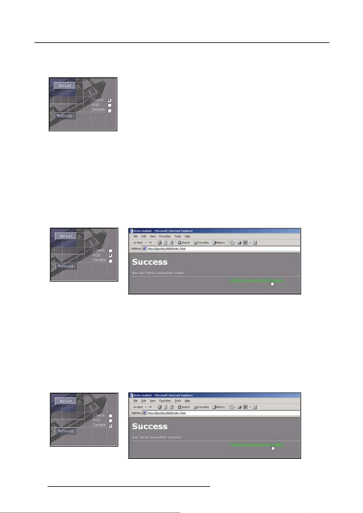
3.1.2 Add user
Add
1. Enter a specific user name and password.
2. Check the add radio button. (image 3-3)
3. Click on submit to add the new user.
A confirmation screen will be displayed. (image 3-4)
4. Click on Clickheretoreturntothelogonpageto return to the logon page.
Image 3-3
Image 3-4
3.1.3 Delete user
Delete
1. Enter the user name and password.
2. Check the delete radio button. (image 3-5)
3. Click on submit to delete the user.
A confirmation screen will be displayed. (image 3-6)
4. Click on Clickheretoreturntothelogonpageto return to the logon page.
Image 3-5
Image 3-6
16 R5976380 XLITE TOOLSET 16/03/2005
Page 21
3.2 Start up Page
Start up menu
When correctly logged on, the following start up menu will be displayed.
1. When a no configuration is detected, the software starts up with the Autodetect window.
3. Logging On
Image 3-7
Autodetect start up page
R5976380 XLITE TOOLSET 16/03/2005 17
Page 22
3. Logging On
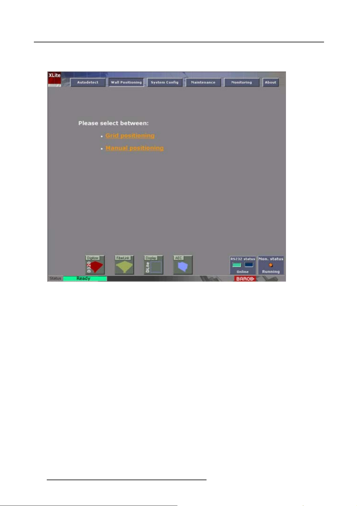
2. When the configuration is known, but no wall positioning is already entered, the software starts up
with the Wall Positioning window.
Image 3-8
Wall positioning start up page
18 R5976380 XLITE TOOLSET 16/03/2005
Page 23
3. Logging On
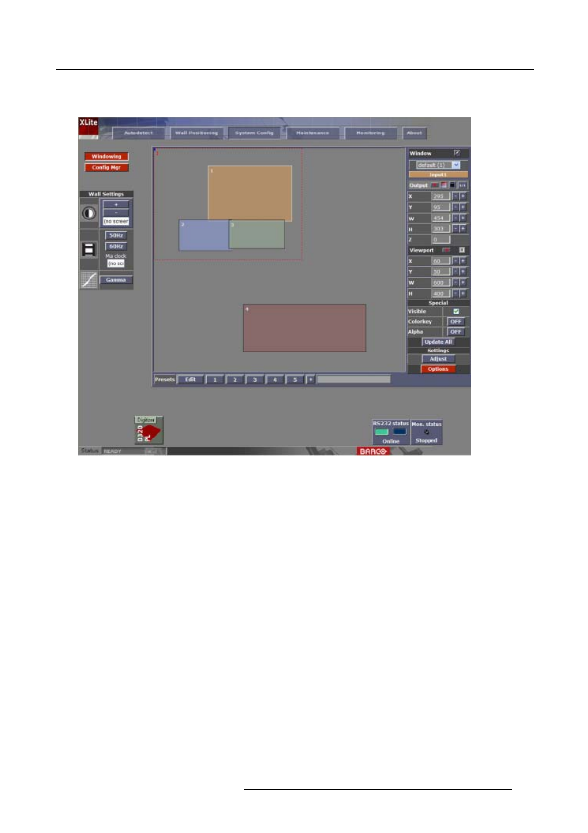
3. When everything is already configured (e.g. for an existing installation), the software starts up with
the System Config window.
Image 3-9
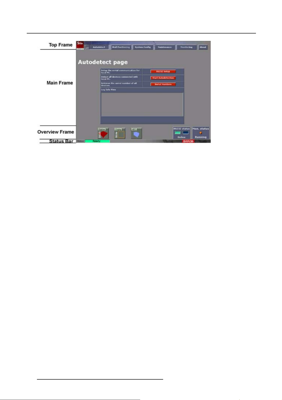
Menu Structure Overview
The basic menus are built up in 4 frames:
• Top Frame for navigating the software.
• Main Frame for the application windows.
• Overview Frame for displaying the connected devices.
• Status Bar.
R5976380 XLITE TOOLSET 16/03/2005
19
Page 24
3. Logging On
Image 3-10
Menu structure overview page
20 R5976380 XLITE TOOLSET 16/03/2005
Page 25
4. AUTODETECT PAGE
Overview
• Autodetect page startup
• RS232 Communication Settings
• Start Autodectection
• Reload parameters from devices
• Serial Numbers
4.1 Autodetect page startup
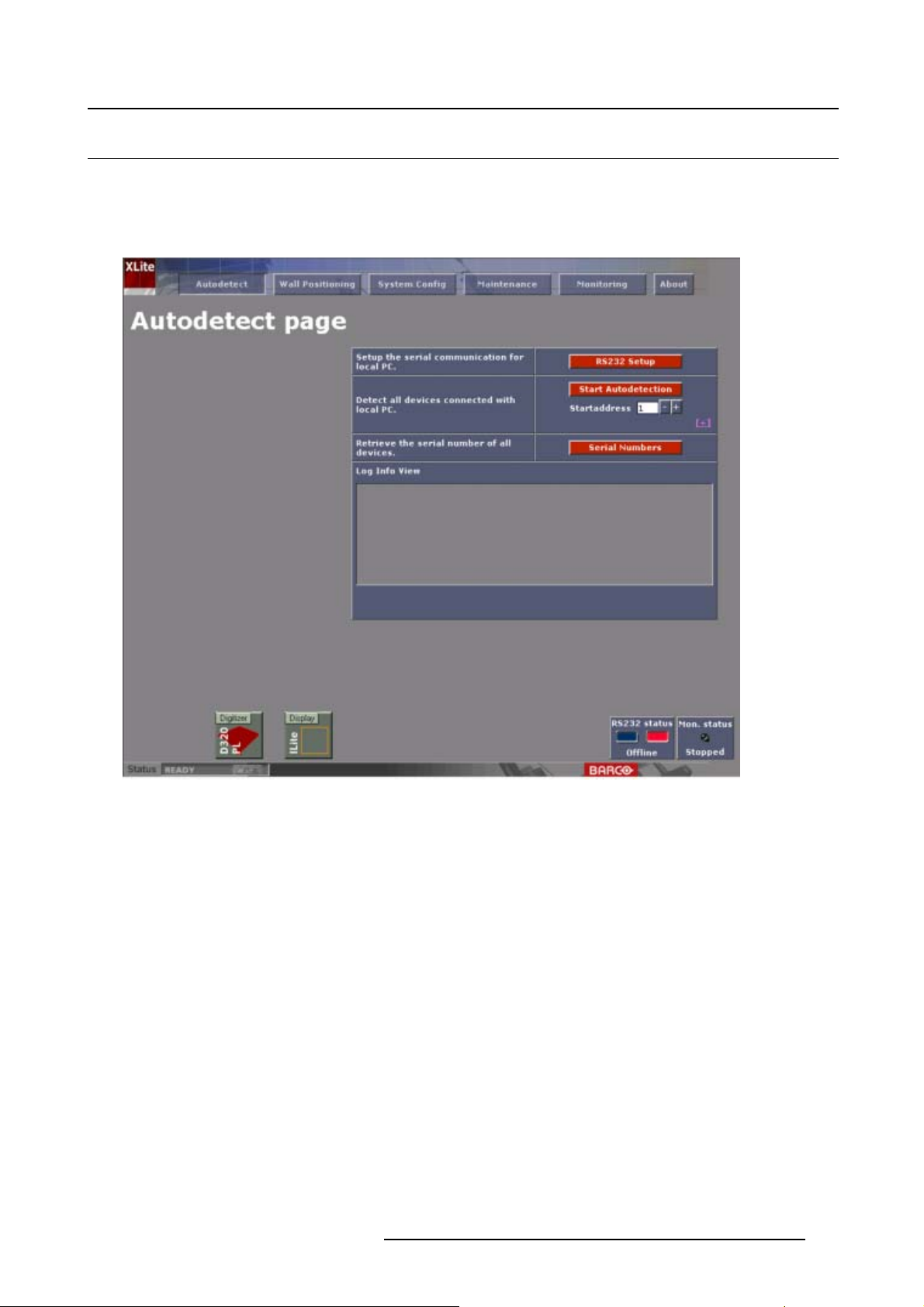
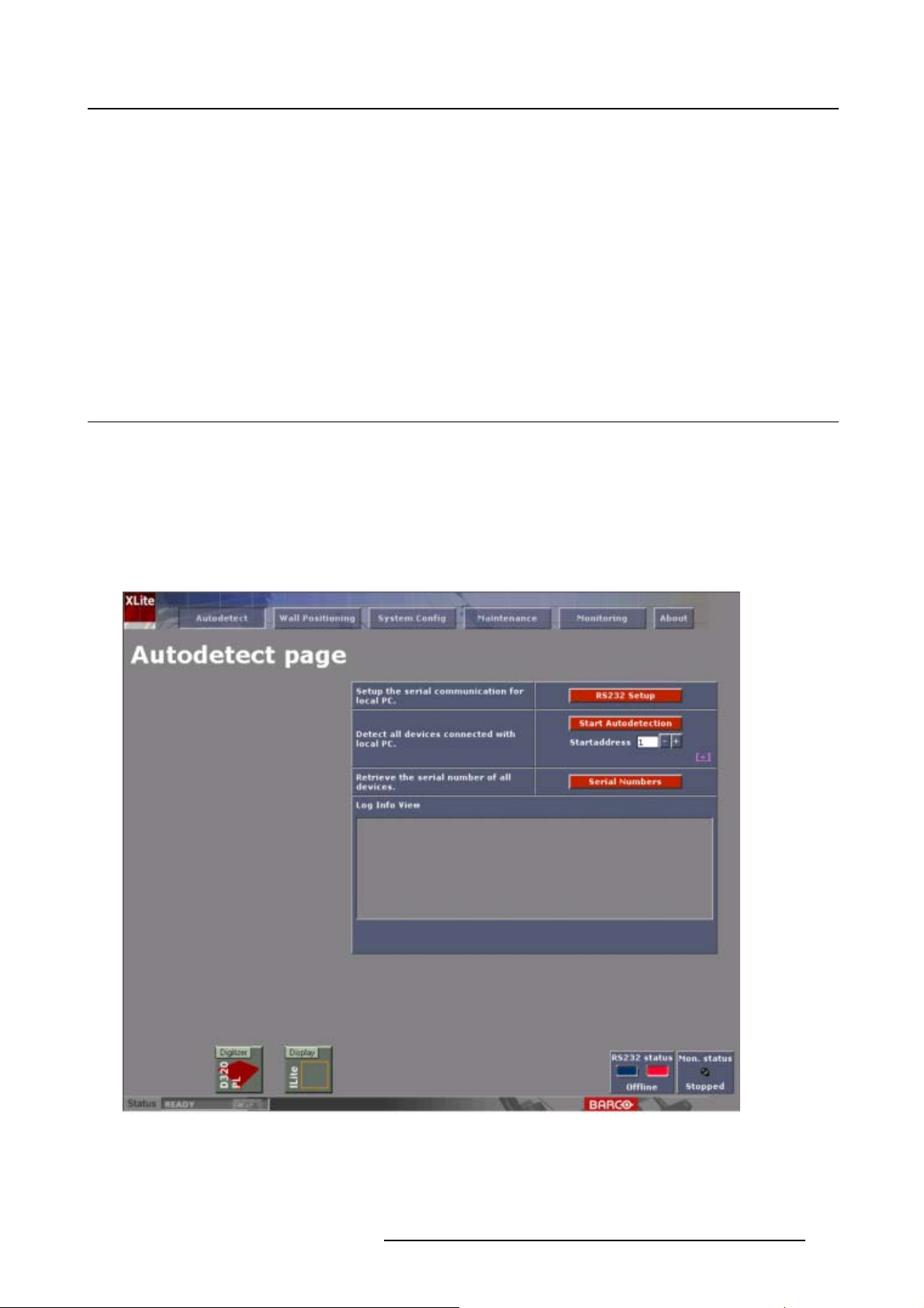
Start up
1. Click on Autodetect.
Note: Autodetection must be done on each occasion after logging on.
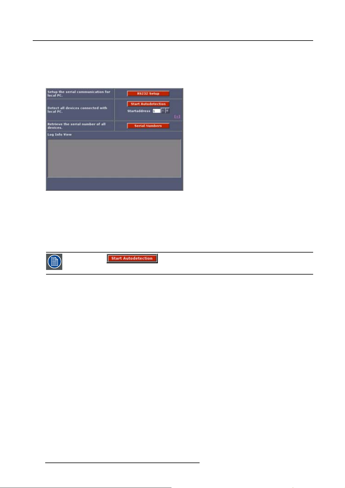
This window is used for the primary detection of devices connected to the local PC.
4. Autodetect Page
During autodetection, all devices will be addressed in the order in which they are detected in the data
link. (image 4-1)
Image 4-1
Autodetect start up page
R5976380 XLITE TOOLSET 16/03/2005 21
Page 26
4. Autodetect Page
Status
The status bar can have 3 states :
• Busy : searching for devices or busy with calculating
• Loading : retrieving device information
• Ready : everything is loaded
Detected d evices
Detected devices will be visible in the ‘overview’ frame.
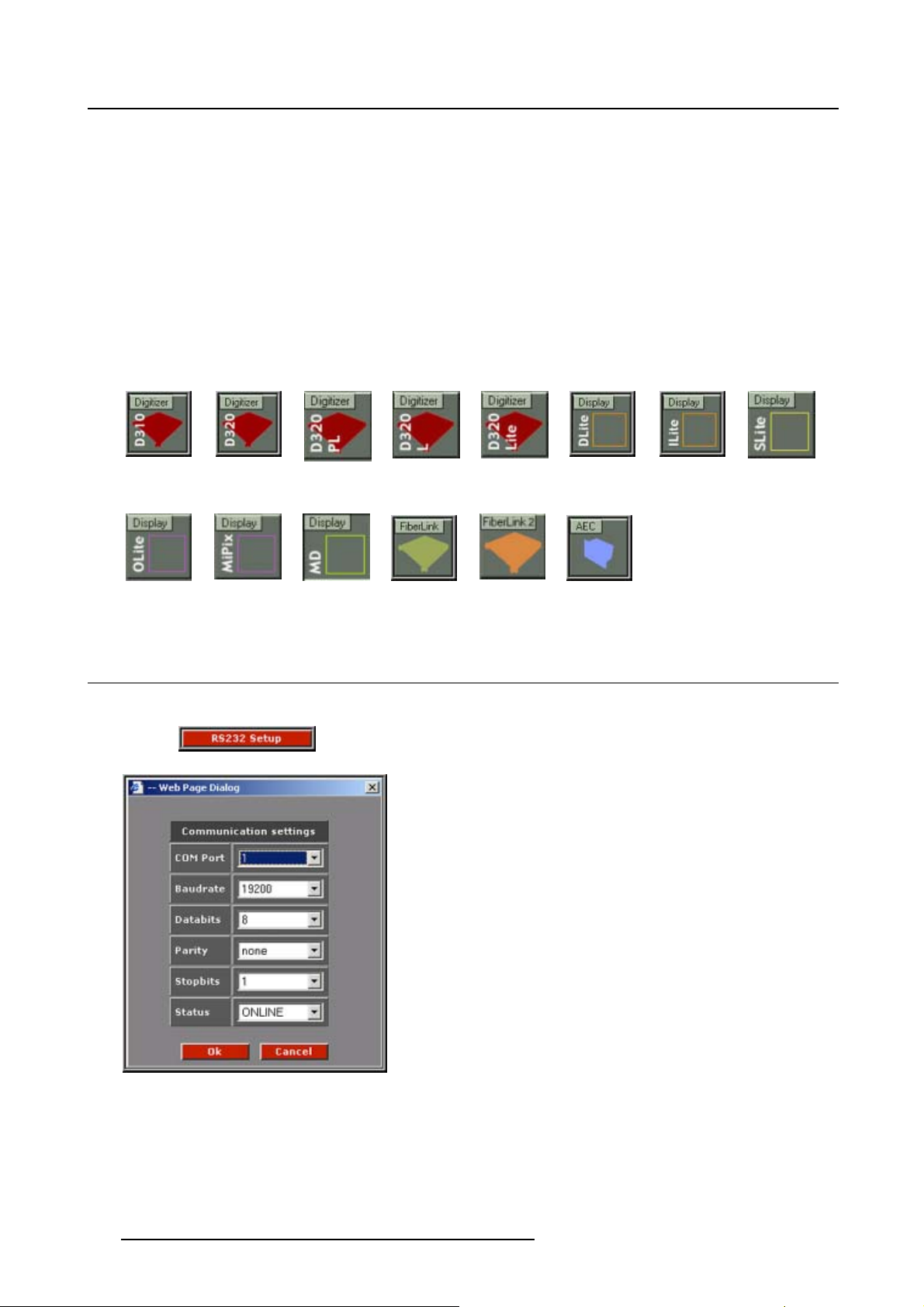
Icons of detected devices will appear if connected within the system configuration.
The following icons are possible:
Image 4-2 Image 4-3
Image 4-10
Image 4-11
Image 4-4
Image 4-12
Image 4-5
Image 4-13
Image 4-6
Image 4-14
Image 4-7 Image 4-8
Image 4-15
4.2 RS232 Communication Settings
Start up
1. Click to reveal the RS232 parameter box. (image 4-16)
Image 4-9
Image 4-16
RS232 Communication settings
ameter values
Par
Adjust the parameter values to suit the serial RS232 communication values between the local PC and
Digitizer.
22
R5976380 XLITE TOOLSET 16/03/2005
Page 27
4. Autodetect Page
Default values will already be filled in.
Communication port Change the Communication port to the serial port as used for connecting
the PC to the Digitizer.
Baudrate
Databits
Parity Read only value. Parity is set to none. No parity check is used.
Stopbits Read only value. Stopbits is set to 1.
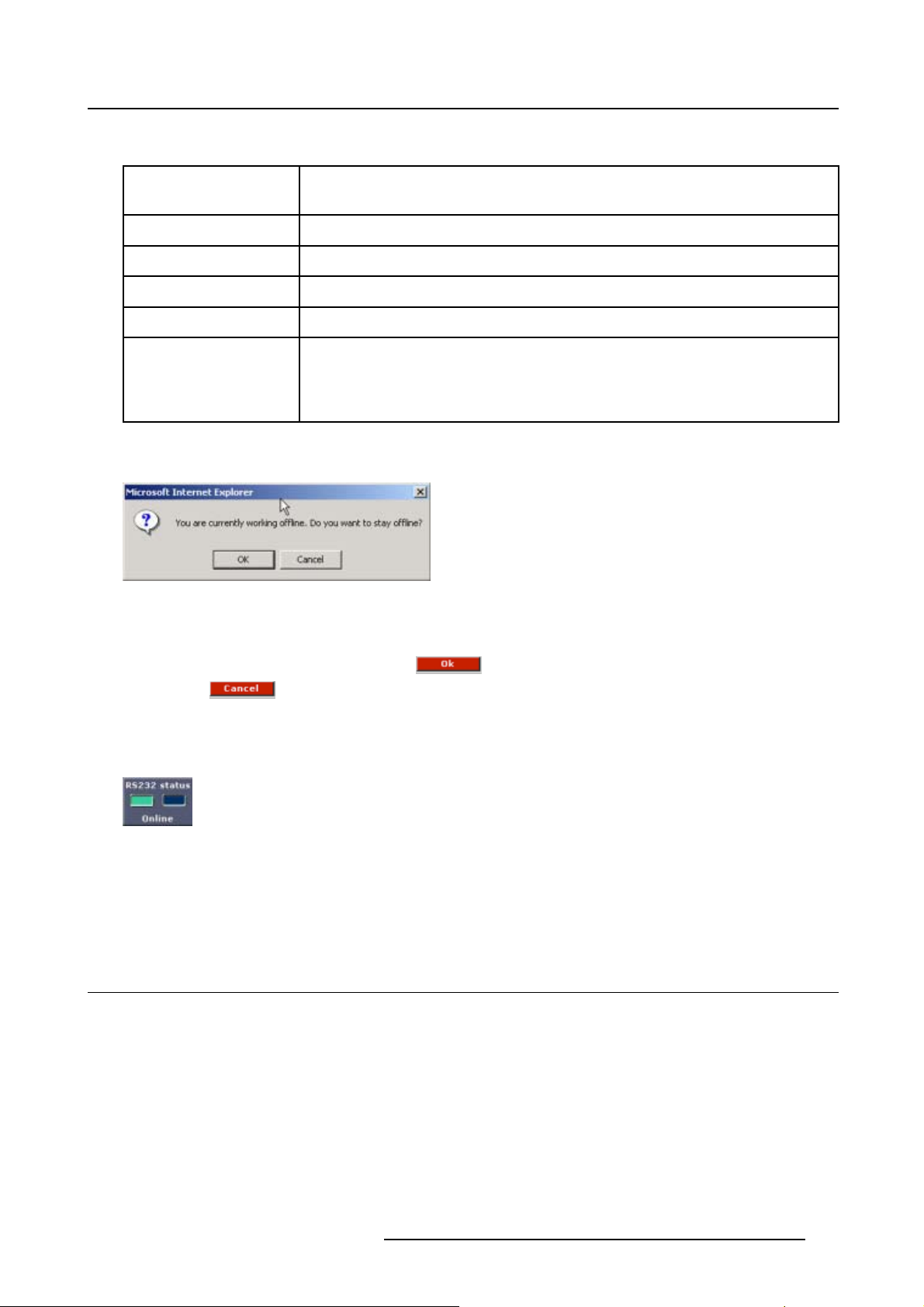
Status This setting is very important as it indicates as to whether the software
When the Status is set to ’off-line’, during some adjustments in system configuration a message will appear
to asked if you want to stay working offline.(image 4-17)
Image 4-17
To stay working off line, click on OK. To return to online, click Cancel.
To finish the Communication settings:
• When the values are entered, click on
• Click on
Read only value. Set up on 19200.
Read only value. Set to 8.
commands have effect on the system being talked to by the XLite ToolSet
software. When online all commands are sent and acted on, when off-line
all commands are not sent to the system devices.
to update any changes made
to exit without updating any changes and leaving the existing values unchanged.
Quick Status Change
Click on the non selected square of the RS232 window to change the status.
Image 4-18
Status change RS232
When a green square is visible : online
When a red square is visible : offline
of RS232
4.3 Start Autodectection
What will be executed?
Depending on the download mode the following will be executed during an autodetection:
Normal download mode (by default):
• Detection of all devices
• Addressing of all devices
• Downloading of device parameters
R5976380 XLITE TOOLSET 16/03/2005
23
Page 28
4. Autodetect Page
Simple download mode:
• Detection of all devices
• Addressing of all devices
Status info will be given in the Log Info View field during the downloading procedure.
Image 4-19
Wait until the status bar indicates ‘Ready’ before proceeding with further operations. Continuing with
further operations could result in the program locking due to conflicts in communication sending and receiving.
Check in the ‘Log Info View’ that detection has finished successfully, if so: continue and go to chapter
“Wall Positioning Page”, if not : check the system devices and the c
Also check all device have been switched on and are in full operational mode.
Repeat the procedure once again if a rectified problem prevented
successful detection originally.
abling connections between them.
SetupoftheStartaddress
The start address can be filled out by entering with the digit keys. Default = 1.
Set up the download mode
1. Click on the + button just below Start address.(image4-20)
The download options become available. (image 4-21)
2. Click on the desired radio button to select the download mode.
Normal
download
Default selected.
Devices will be detected, addressed and all necessary parameters will be
downloaded during an auto-detection.
24
Simple
download
Devices will be detected, addressed and only the basic parameters will be
downloaded from these devices. This option is fa
values for certain settings.
Practical use : hot swap of a tile. Tile can be detected and addressed. Then
tile can be first calibrated etc. and then a download parameters of all devices
can be executed.
R5976380 XLITE TOOLSET 16/03/2005
ster, but may result in undefined
Page 29
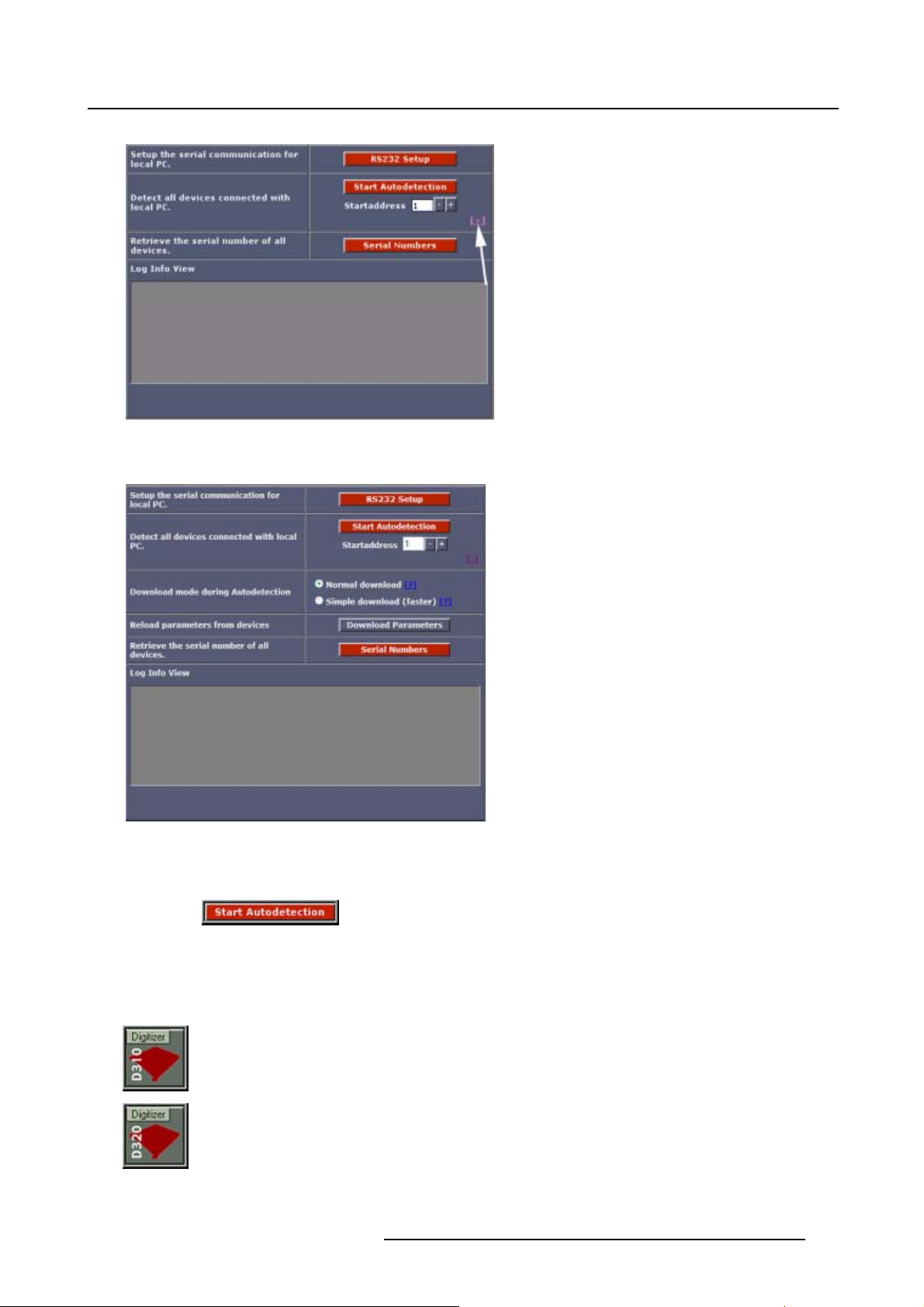
Image 4-20
Select download options
4. Autodetect Page
Image 4-21
Download options
Start up the Autodetection
1. Click on to initiate the detection process.
Detected devices will be visible in the ’overview’ frame.
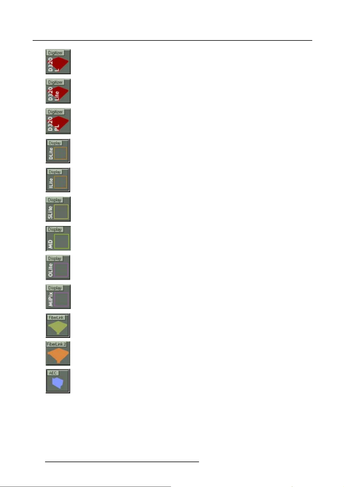
Available icons
The following icons of detected devices will appear if connected within the system configuration.
Digitizer D310
Digitizer D320
R5976380 XLITE TOOLSET 16/03/2005
25
Page 30
4. Autodetect Page
Digitizer D320L
Digitizer D320Lite
Digitizer D320PL
DLite Display
ILite Display
Slite Display
MD Display
OLite Display
MiPix Display
FiberLink
FiberLink 2
AEC
26 R5976380 XLITE TOOLSET 16/03/2005
Page 31

4. Autodetect Page
4.4 Reload parameters from devices
When can it be applied ?
A reload is mostly useful after an auto-detection has taken place with simple download mode.
The devices parameters will be downloaded locally.
How to reload ?
1. Click on the button.
The parameters of all devices will be reloaded.
4.5 Serial Numbers
Start up
1. Click on to initiate the serial detection process.
2. A pop up screen appears to ask to display the information in a separate window. (image 4-22)
3. Do you want the overview in a separate window?
If yes, click ok (image 4-23)
Note: Print out this page or save this page in a text file for later use.
If no, click Cancel. (image 4-24)
Image 4-22
Image 4-23
Serial numbers on separate page
R5976380 XLITE TOOLSET 16/03/2005 27
Page 32

4. Autodetect Page
Image 4-24
Serial numbers on Autodetect page
28 R5976380 XLITE TOOLSET 16/03/2005
Page 33

5. WALL POSITIONING PAGE
Overview
•Startup
• Grid positioning
• Manual Positioning
• MiPix Configurator
5.1 Start up
Why?
Thenextstepaftertheautodetection, is wall positioning.
This is necessary to position the LED wall in the total video output field.
Two ways are possible to position the tiles:
• Grid positioning, automatic positioning of the tiles.
• Manual positioning.
5. Wall Positioning Page
Start Up
1. Click on to start up the wall positioning page. (image 5-1)
Selection between Grid positioning and Manual positioning is possible for DLite, ILite, ILite MD and
SLite displays.
R5976380 XLITE TOOLSET 16/03/2005
29
Page 34

5. Wall Positioning Page
Image 5-1
Wall positioning start up page
5.2 Grid positioning
Overview
• Selecting Grid positioning
• Grid Dimensions
• Define the Tile Linkage
• Wall Positioning for DLite, SLite, OLit
• Wall Positioning for MiPix
• MiPix setup
5.2.1 Selecting Grid positioning
Why?
The Grid positioning positions automatically all tiles. It provides the possibility to define the start-position
(upper left corner), and also the ti
le resolution of the LED wall.
Start Up
e and ILite walls
1. Click on Grid positioning to start up the wall positioning page. (image 5-2, image 5-3, image 5-4)
Note: When ’include’ in ’Tile Linkage’ is not checked, the dark orange square is not a tile.
30
R5976380 XLITE TOOLSET 16/03/2005
Page 35

5. Wall Positioning Page
The dark-orange field corresponds with the start of the data linkage.
Every orange square on the wall positioning screen corresponds with a tile in the wall or with a string
when MiPix.
For ILite 6/8/10/12, DLite, SLite and OLite
Image 5-2
Wall position start page after Grid positioning (for DLite, SLite, OLite and ILite 6/8/10/12).
R5976380 XLITE TOOLSET 16/03/2005 31
Page 36

5. Wall Positioning Page
For ILite 3:
Image 5-3
Wall positioning start page after Grid p
ositioning (for ILite 3)
32 R5976380 XLITE TOOLSET 16/03/2005
Page 37

For MiPix :
5. Wall Positioning Page
Image 5-4
Wall positioning start page after Grid positioning (for MiPix)
5.2.2 Grid Dimensions
In a stack configuration, wall positioning has to be done for each screen of the display.
Horizontal (Rows)
Fill in the number of tiles horizontally, which form the display area.
Image 5-5
Vertical (Columns)
Fill in the number of tiles vertically, which form the display area.image 5-5
R5976380 XLITE TOOLSET 16/03/2005
33
Page 38

5. Wall Positioning Page
5.2.3 Define the Tile Linkage
Start
This refers to the data link orientation. Select the start corner of the data cable while viewing the screen
from the front. This is the location of the first tile (the tile that is connected directly to the Digitizer or
FiberLink RX) in the display.
Possible positions :
• Bottom left
• Bottom right
•Topleft
• Top right
Image 5-6
Direction
Direction specifies how the tiles of the LED wall are linked together.image 5-6
Select the data link direction, either horizontally or vertically, according to the data cabling path. It is
recommended that this is normally done horizontally to make possible trouble shooting more easy.
The dark-orange field in the GUI corresponds with the start point of the data linkage.
When Include is checked, the first tile is incorporated.
Tile Addressing
Individual addresses are given in accordance to the sequence in which devices are detected during the
Auto Detection procedure. Hence addresses start with the digitizer and follow the data cabling path to
sequential address all other devices. It is not possible to manipulate the addresse
s manually.
5.2.4 Wall Positioning for DLite, SLite, OLite and ILite walls
Start
Give up the coordinates in pixels for the horizontal and vertical start pos
wall.
Normal values are :
• Horizontal = 52
•Vertical=36
ition of the upper left corner of the
34
R5976380 XLITE TOOLSET 16/03/2005
Page 39

5. Wall Positioning Page
For ILite 6/8/10/12, DLite,
SLite and OLite
Image 5-7
For ILite 3
Image 5-8
Tile resolution
Give up the tile resolution in pixels. (image 5-7)
The tile resolution depends on the type of wall.
Maximum default values are already filled in for the connected display. To change the resolution click on
the - or + button next to horizontal or vertical. The up scaling indication will change while clicking on the
+ or - button.
Dimensions
Overview of the wall dimensions.(image 5-7)
Rotation (only for ILite 3)
The result of combination of ILite 3 tiles can be landscape or portrait. As the content can be created in the
other direction, it is possible to rotate the content so that is perfectly displayed.
To rotate the content, click on the drop down box next to Rotation and select the desired rotation.
e5-9
Imag
Rotating content for ILite3
The following rotations are possible:
•normal
• 90° clockwise
• 180°
• 90° counter clockwise
Update
Click on to apply this wall positioning.
R5976380 XLITE TOOLSET 16/03/2005
35
Page 40

5. Wall Positioning Page
5.2.5 Wall Positioning for MiPix
Start
Give up the coordinates in pixels for the horizontal and vertical start position of the upper left corner of the
MiPix wall.
Normal values are :
• Horizontal = 52
•Vertical=36
Image 5-10
Tile resolution
The resolution depends on the selected working mode for MiPix.
The maximum default values are already filled in for th
on the - or + button next to horizontal or vertical. The up scaling indication will change while clicking on
the + or - button.
e connected display. To change the resolution click
MiPix setup
For more explanation see "MiPix setup", page 37.
Pixel gap
Number of pixels between 2 MiPix units.
Grid gap
Number of pixels between 2 strings (chains) of MiPixes. Column way and row way.
Dimensions
Overview of the wall dimensions.
Update
Click on to apply this wall positioning.
When Only start pos is checked, only the start positions of each MiPiX module will be sent. This is a faster
update as the pixel mapping will not be sent to the MiPiX modules.
36
R5976380 XLITE TOOLSET 16/03/2005
Page 41

5.2.6 MiPix setup
Start up and Introduction
1. Click on button.
The Device set up window appears. (image 5-11)
Overview of the specific areas in the device set up window:
1 Working mode selection
2
String setup (chain)
3
Direction string (chain)
4
Number of blocks per string (chain). Maximum allowed : 32
5
Preview area
6 Preview color index
For a chain configuration, one module can contain maximum 4 chains and each chain can contain 32
blocks. Each block is 4 pixels.
For a tile configuration, one module can contain 1 tile with 4 nested chains in it. Each chain contains
32 blocks. Each block is 4 pixels.
5. Wall Positioning Page
For a custom configuration, one module
at random. Each string can contain 32 blocks. Each block is 4 pixels.
can contain maximum 4 strings of blocks which can be placed
Image 5-11
MiPix device setup window
Working mode
k on the drop down box and select the corresponding working mode.
1. Clic
R5976380 XLITE TOOLSET 16/03/2005
37
Page 42

5. Wall Positioning Page
Available working modes:
4 linear chains of pixelblocks : One module can contain 4 different chains of blocks which can be placed
2 x 2 or 4 x 1 or 1 x 4, depending on the direction.
Tiles Rental : 11 x 11 blocks
Tiles : 11 x 11 blocks
Custom pixel-mapping : blocks can be placed as desired on the working field.
Workingmode:4chainsofpixelblocks
1. Click on the drop down box and select 4 linear chains of pixelblocks. (image 5-12)
2. Select the String setup byclickingonthedropdownbox.
The choices will be different for Vertical and Horizontal:
Vertical
o
2x2
o
1x4
o
4x1
Horizontal
o
2x2
o
1x4
3. Select the String direction by clicking on the drop down box.
Possible choices:
- Horizontal
-Vertical
Overview drawings: (image 5-13)
Image 5-12
Linear chain setup
38 R5976380 XLITE TOOLSET 16/03/2005
Page 43

5. Wall Positioning Page
1
2
3
4
1234 12
2 x 2 H 1 x 4 V
2 x 2 V
34
A
B
N
CC
1 x 4 H
4 x 1 V
Image 5-13
Configuration overview
A Chain
B Port number (see installation manual for more explanation)
C Possible start position of data connection
1
3
2
4
1
2
3
4
Working mode : Rental tiles 11 x 11 blocks
1. Click on the drop down box and select tile Rental : 11 x 11.
The corresponding preview window will be displayed. (image 5-14)
Image 5-14
Rental tile 11 x 11 setup
R5976380 XLITE TOOLSET 16/03/2005 39
Page 44

5. Wall Positioning Page
Workingmode:11x11tiles
1. Click on the drop down box and select tile : 11 x 11.
The corresponding preview window will be displayed. (image 5-15)
Image 5-15
11 x 11 tile setup
Working mode : Custom pixel-mapping
1. Click on the drop down box and select Custom pixel-mapping
A corresponding preview window will be displayed. (image 5-16)
2. Click OK.
The MiPix configurator applet will be loaded (see "MiPix Configurator", page 49 for more explanation).
.
40
R5976380 XLITE TOOLSET 16/03/2005
Page 45

5. Wall Positioning Page
Image 5-16
MiPix custom pixel-mapping selection
5.3 Manual Positioning
Overview
• Selecting Manual positioning
• Selection mode
• Cutout coordinates for DLite/SLite/ILite/OLite
• Cutout coordinates for MiPix
• String functions for MiPiX
• Export Cutout coordinates
5.3.1 Selecting Manual positioning
Why?
The Manual positioning makes it possible to position your tiles in the way you want to have them.
Start Up
1. Click on Manual positioning to start up the wall positioning page. (image 5-17, image 5-18)
Note: When ’include’ in ’Tile Linkage’ is not checked, the dark orange square is not a tile or string for
MiPix.
R5976380 XLITE TOOLSET 16/03/2005
41
Page 46

5. Wall Positioning Page
The dark-orange field corresponds with the start of the data linkage.
Every orange square on the wall positioning screen corresponds with a tile in the wall.
Image 5-17
Wall positioning page for manual positioning for D/I/S/OLite
42 R5976380 XLITE TOOLSET 16/03/2005
Page 47

5. Wall Positioning Page
Image 5-18
Wall positioning page for manual positioning for MiPix
5.3.2 Selection mode
Possibility
ile selection can be done on a single base or on a multiple base. When multiple tile (strings for MiPix)
T
selection is done, moving the tiles at once are possible.
Set up of the selection mode
1. Click on the drop down box just below Selection mode. (image 5-19)
e drop down box opens. Single or Multiple are possible.
Th
2. Select the desired mode.
Image 5-19
lection mode
Se
How to make a multiple selection
1. If the tiles (strings for MiPix) you want to select are just below each other in the Module list, push the
Shift button and click with your mouse on the first and a last one in the desired selection. (image 5-20)
e selected tiles (strings for MiPix) become orange.
Th
2. If the tiles (strings for MiPix) you want to select are not below each other in the Module list, push the
CTRL button and click with your mouse on each tile (string for MiPix) you want to select. (image 5-21)
The selected tiles (strings for MiPix) become orange.
R5976380 XLITE TOOLSET 16/03/2005
43
Page 48

5. Wall Positioning Page
Image 5-20
Multiple selection via Shift button
44 R5976380 XLITE TOOLSET 16/03/2005
Page 49

5. Wall Positioning Page
Image 5-21
Multiple selection via CTRL button
To physically see which tile is selected in the wall, switch Internal Patterns from Off to
On. The selected tile will display an internal pattern.
To scroll true the file list, use the red up or down arrows in the right bottom corner of
the Module list pane.
5.3.3 Cutout coordinates for DLite/SLite/ILite/OLite
What can be filled out
he start coordinates determine the position of each tile in the wall. These coordinates have to be entered
T
for each tile.
The size values determine the displayed resolution of the image. To calculate these values, starting from
the native tile resolution, use the following formulas:
Vertical Size = (image width / display width)* maximum tile resolution.
Horizontal Size = (image height / display height) * maximum tile resolution
The result of the calculation should be rounded to the lower digit. These result values for Vertical Size
nd Horizontal Size should be entered for each tile. When the values are lower that the tile resolution, the
a
image will be scaled (enlarged) to be displayed on the hole screen.
If you use the native resolution of the tile (depending on the type of wall) in stead of the calculated values,
the image will only be displayed on a part of the wall in stead of on the hole wall.
R5976380 XLITE TOOLSET 16/03/2005
45
Page 50

5. Wall Positioning Page
How to fill out the cutout coordinates
1. Fill out the start position (horizontal and vertical) of the tile by clicking on the input field and entering the
value with the keyboard. (image 5-22)
Or,
click on the - or + button next to Horizontal or Vertical.
2. Calculates the pixels size with the above mentioned formulas.
3. Click in the input fields and enter the appropriate value with the keyboard.
Or,
click on the - or + button next to Size Hor. or Size Vert.
Image 5-22
Cutout coordinates
Screen d imensions
Overview of the wall dimensions are given in pixels.
Apply m ode
When Auto apply is checked, the changes will be applied immediately to the wall (online mode).
When the Auto apply is not checked, off line working is possible. Everything can be changed. Click then
on
to send all changes to the wall.
5.3.4 Cutout coordinates for MiPix
What can be filled out
The start coordinates determine the position of e
entered for each string.
The size values determine the displayed resolution of the image. These values are filled out when the
working mode is selected.
Pixel gap : the horizontal and vertical distance between two MiPix blocks.
ach string in the wall. These coordinates have to be
How to fill out the cutout coordinates
1. Fill out the start position (horizontal and vertical) of the string by clicking on the input field and entering
the value with the keyboard. (image 5-23)
Or,
click on the - or + button next to Horizontal or Vertical.
46
R5976380 XLITE TOOLSET 16/03/2005
Page 51

5. Wall Positioning Page
2. Click now first on button before changing any values for size and pixels gap.
For a complete explanation about MiPix setup, see "MiPix setup", page 37.
When finishing the MiPix setup, the Size and Pixel gap will be filled out.
3. As the size is already filled out, small corrections can be made to the horizontal and vertical size.
4. The pixel gap can be freely adapted for string configuration.
The pixel gap for the tile mode is by default 2 pixels.
Image 5-23
Cutout coordinates MiPix
Screen d imensions
Overview of the wall dimensions are given in pixels.
Apply m ode
When Auto apply is checked, the changes will be applied immediately to the wall (online mode).
When the Auto apply is not checked, off line working is possible. Everything can be changed. Click then
on
When Only start pos. is check, only the start position of the modules will be sent to the wall when
is clicked.
to send all changes to the wall.
5.3.5 String functions for MiPiX
String colors
1. Click on .
An internal pattern with fixed colors per string will be generated to check the string connections.
String 1 = red, string 2 = green, string 3 = blue and string 4 = yellow.
R5976380 XLITE TOOLSET 16/03/2005
47
Page 52

5. Wall Positioning Page
String directions
1. Click on .
A running light pattern is activated so that the directions of the strings can be checked.
5.3.6 Export Cutout coordinates
How to export
1. Click on the export icon in the Module list pane. (image 5-24)
The cutout coordinates will be displayed in a separate window. (image 5-25)
2. Print out this window or save it in text file for further use.
Image 5-24
Export data selection
48 R5976380 XLITE TOOLSET 16/03/2005
Page 53

5. Wall Positioning Page
Image 5-25
Cutout coordinates exported
5.4 MiPix Configurator
Overview
• MiPix configurator overview
• Show preview stored design
• Create new design
• Add blocks to a design
• Edit existing design
• Block manipulations
• Delete a design
• Zoom in - Zoom out
• Associate designs to devices
• Intern
al pattern
When starting up the MiPix configurator for the first time, a security warning will be
displayed. To avoid displaying this warning in the future, select Always.
R5976380 XLITE TOOLSET 16/03/2005 49
Page 54

5. Wall Positioning Page
5.4.1 MiPix configurator overview
Pixel block
One block, unit containing several pixels. E.g. 4 pixels. Each pixel can light up in the 4 different
colors.
Objectives of the MiPix configurator
The MiPix configurator allows the user within the designer part of the configurator to place pixel blocks in
a custom way on the workspace and create in that way a design (template) configuration. Therefore, two
ways to place these pixels blocks in a workspace are possible.
• the manual way : this way can place the blocks from a particular string on any place in the workspace.
• the auto fill way : the software calculates the best position of the blocks within a viewport on the
workspace.
Once the blocks are placed in one or the other way,
• it is possible to reposition each block
• to rotate a block for easy physical mounting of that block or to comply with the physical mounting.
• delete blocks or add extra blocks if still blocks left to be placed.
Once the design (template) configuration is finished, it can be saved. This design can now be associated
with one or more controller modules (devices).
MiPix configurator window
Image 5-26
MiPix configuration start up window
1. Tool bar
2. Stored designs (templates)
3. Device list (controller modules)
4. Update configuration
5. Design preview window
6. Status bar
7. Physical check with real wall.
50
R5976380 XLITE TOOLSET 16/03/2005
Page 55

5.4.2 Show preview stored design
What is possible ?
A preview of each stored design can be given in the preview pane.
Howtoshowapreview?
1. Single click on a design name in the Stored designs pane (1). (image 5-27)
A preview will be displayed in the preview pane (2).
5. Wall Positioning Page
Image 5-27
Show preview
5.4.3 Create new design
Overview
•Startup
• New block configuration
• OutlineinGrid
• Auto fill
• Advanced settings for auto fill
• Some typical examples where auto fill is very us
• Manual fill
• Outline border On or Off
• The design window
• Save a design
eful
R5976380 XLITE TOOLSET 16/03/2005
51
Page 56

5. Wall Positioning Page
5.4.3.1 Start up
How t o start up ?
1. Click on Create a new design icon ( ).
The New control block configuration window opens. (image 5-28)
Image 5-28
New control block configuration window
5.4.3.2 New block configuration
Name
Enter a name for the new configuration.
Workspace dimensions (read only)
The workspace is the area where a design (template) can be created.
The workspace dimensions are limited by the hardware of the controller un
As only one controller unit is available (at the moment), only 128 x 128 pixels are possible.
it.
Number of Strings (read only)
The number of strings are limited by the used controller. As many strings can be connected to the controller as the number of output ports mounted on this control.
Number of blocks per string (read only)
The number of blocks per string depends on the maximum number of pixels that can be driven by the
used controller and by the number of pixels per block.
E.g. when using a controller with a maximum output of 128 pix
pixels, then only 128 divided by 4, 32 blocks can be connected in one string.
els per output port and MiPix blocks of 4
Block resolution (read only)
Block resolution is the number of pixels available in one block. E.g. 2 x 2
The block resolution influences the number of blocks p
er string.
5.4.3.3 Outline in Grid
Definition
Outlineingridis a well defined area within the workspace to facilitate the user with placing its bocks on
the design or to allow an auto fill. The outline is indicated by a well defined border which can be switched
off and on again.
52
R5976380 XLITE TOOLSET 16/03/2005
Page 57

5. Wall Positioning Page
Defining a Outline in Grid
The outline is defined by its start position, its width and height.
Image 5-29
Viewport in grid set up
Enter first the X and Y coordinate to define the start position. Therefore, click in the input field and enter
the desired value or click on the up or down arrows next to the coordinate value until the desired value is
reached.
Enter the desired width or height to define a viewport in grid. Therefore, clic
the desired value or click on the up or down arrows next to the coordinate value until the desired value is
reached.
k in the input field and enter
5.4.3.4 Auto fill
Auto fill can only be activated when Outline in G rid is defined.
How to set up ?
1. Check the check box just before Auto fill (1). (image 5-30)
The auto fill function is activated.
2. Select the way auto fill should handle. Click in the drop down b
- Snake wise: the software starts by default in the upper left corner of the outline and goes from left
to right until the bounderies of the outline are reached. Then it goes one down and continues from
right to left. It starts with the first string, continues with the second string, then the third string and
ends with the fourth string. It interrupts the auto fill when the outline is filled up or when the blocks
(4 x 32) are placed. (image 5-31)
There are some special cases where snake wise fill up always starts for the 4 strings at the same
side. E.g. when outline set up matches exactly the number of pixels blocks, such as 64 with no gap.
The rows or columns will be filled up starting at the same side and that to make the connection with
the controller more easier.
- By quadrant : the software will start at the joining corners of the quadrants of the viewport. Each
quadrant will be filled up with another string and in most cases each string will contain the same
amount of blocks. This depends on the width and h
height = 7 all string will contain the same amount of blocks. (image 5-32)
Whether or not the same amount of blocks for each string is used depends on the combination of
width, height, horizontal gap, vertical gap a
fill with width = 27, height = 35, horizontal gap = 1 and vertical gap = 1 and a MiPix block (2x2), this
method will not fill the area with the same amount of blocks for each string.
nd the dimension of the block. E.g. for outline and auto
eight setting of the outline. E.g. width = 5 and
ox (2) and select the desired way (3).
R5976380 XLITE TOOLSET 16/03/2005
53
Page 58

5. Wall Positioning Page
Image 5-30
Set up auto fill
23
23
23
23
23
01
01230123012301230123012301230123012301
23
01
01230123012301230123012301230123012301
23
01
23
01
01
23
23
01
23
01
012301
23
01
23
012301
23
23
01
01
01
23
23
01
01
23
23
01
01
0123012301230
23
23
01
01
0123012301230
23
23
01
01
0123012301230123012301230123012301
23
23
01
01
01
23
01
23
01
23
01
23
01
23
01
01
23
01
23
01
23
01
23
01
23
01
23
01
23
01
23
01
1
01
3
2
2
23
01
1
012301230123012301
23
23
01
23
1
0
01
23
01
23
01
3
23
01
23
01
23
01
01
2
01
23
01
23
01
3
23
01
23
01
23
01
01
3
2
23
23
23
01
23
23
01
23
01
01
2
23
01
23
01
23
01
23
01
23
01
23
01
3
23
01
23
01
23
01
23
23
01
23
23
01
01
3
2
23
23
3
2
01
23
23
01
01
01
23
01
01
23
23
012301230123012301
01
01
23
23
012301230123012301
01
01
23
23
01
01
23
23
2
3
3
01
01
01
23
23
012301230123012301
01
01
23
23
23
01
23
01
23
01
23
2
01
01
23
01
23
3
23
01
23
01
23
01
23
2
01
01
23
01
23
3
2
01
01
01
01
01
23
01
23
01
23
01
23
3
01
23
01
23
012301230123012301
01
01
23
23
23
012301230123012301
01
01
23
23
23
2
3
3
01
230123012301230123
0 1
01
01
2
23
23
01
230123012301230123
0 1
01
01
23
23
23
230123012301230123
0 1
01
23
01
23
2
01
01
23
01
23
3
01
23
01
23
2
01
01
23
01
23
3
01
23
01
23
2
01
0
23
0 1
23
3
23
23
2
01
1
Image 5-31
Auto fill snake wise, viewport area 22 x 22
Image 5-32
Auto fill by quadrant, outline area 22 x 22
Remarks
The auto fill will search for the best rotation of the blocks. Those block where the software cannot calculate
the best rotation are indicated by a light blue background. These blocks should be manually rotated till
the correct position is obtained. For more information, see "Rotate selected blocks", page 67.
When the auto fill is finished, it is still possible to place extra blocks manually in the
design and that as long as there are blocks available.
5.4.3.5 Advanced settings for auto fill
What is possible with the advanced settings ?
The following items can be defined :
• Horizontal and vertical pixel gap.
• String direction, horizontal or vertical
• Start position of the first string when using snake wise fill up.
54
R5976380 XLITE TOOLSET 16/03/2005
Page 59

By default :
• Horizontal and vertical gap = 0
• String direction = horizontal
• Start position = upper left
Start up the advanced settings
1. Click on the Advanced >> button. (image 5-33)
Note: Only active when Viewport in Grid and Auto fill are checked.
The options window will be added.
5. Wall Positioning Page
Image 5-33
Advanced auto fill options
Gap set up
1. If you want to set a Horizontal gap, click in the input field next to Horizontal gap and enter the pixel gap
youwanttouse.
Or,
click on the up or down arrow next to Horizontal gap until the desired value is reached. (image 5-34)
2. If you want to set a Vertical gap, click in the input field next to Vertical gap and enter the pixel gap you
want to use.
Or,
click on the up or down arrow next to Vertical gap until the desired value is reached.
01
23
23
23
23
23
23
23
01
01
012301230123012301
23
01
01
23
0123012301230123012301
23
01
23
01
23
23
01
01
012301230123012301
01
23
01
23
01
01
23
01
23
01
01
23
01
23
01
23
23
23
01
23
01
23
01
01
23
01
23
23
01
23
23
01
01
23
01
23
01
23
01
23
01
23
01
23
01
01
23
Image 5-34
Auto fill, viewport 22 x 22, horizontal and vertical gap 1
R5976380 XLITE TOOLSET 16/03/2005 55
Page 60

5. Wall Positioning Page
String direction
1. Click on the desired radio button to set up the string direction.
Note: The block connected with the controller has a shaded background.
Horizon-
the bocks will be placed in a horizontal way. From left to right or from right to left.
tal
Vertical
the bocks will be placed in a vertical way. From top to bottom or from bottom to top.
See image 5-35, image 5-36.
23
23
23
23
23
23
23
23
23
01
01230123012301230123012301230123012301
23
01
01230123012301230123012301230123012301
23
01
23
01
01
23
23
01
23
01
012301
23
01
23
012301
23
23
01
01
01
23
23
01
01
23
23
01
01
0123012301230
23
23
01
01
0123012301230
23
23
01
01
0123012301230123012301230123012301
23
23
01
01
01
23
01
23
01
23
01
23
01
23
01
01
23
01
23
01
2
23
01
23
23
01
23
01
01
01
23
23
01
01
23
23
01
01
1
01
01
3
3
2
2
23
23
01
01
1
012301230123012301
23
23
01
01
23
23
1
01
0
Image 5-35
Auto fill, viewport 22 x 22, horizontal string direction
01
23
01
23
01
3
23
01
23
01
23
01
01
3
2
01
23
01
23
01
23
01
23
01
23
01
23
01
3
2
23
01
23
01
01
23
23
01
01
01
2
23
01
23
23
01
01
23
23
01
0
23
01
01
23
23
23
3
01
23
3
2
23
01
23
01
23
01
23
01
23
01
23
01
23
01
23
01
23
01
23
01
23
01
23
01
0
0
1
0
1
0
1
0
1
0
1
0
1
0
1
0
1
0
1
0
1
23
01
23
01
23
01
23
01
23
01
23
01
23
01
23
01
23
01
23
01
23
01
2
1
3
0
2
1
3
0
2
1
3
0
2
1
3
0
2
1
3
0
2
1
3
0
2
1
3
0
2
1
3
0
2
1
3
0
2
1
3
0
2
1
3
0
2
1
3
2
3
2
3
2
3
2
3
2
3
2
3
2
3
2
3
2
3
2
3
2
3
1
0
1
0
1
0
1
0
1
0
1
0
1
0
1
0
1
0
1
0
1
0
1
3
2
0
2
3
1
3
2
0
2
3
1
3
2
0
2
3
1
3
2
0
2
3
1
3
2
0
2
3
1
3
2
0
2
3
1
3
2
0
2
3
1
3
2
0
2
3
1
3
2
0
2
3
1
3
2
0
2
3
1
3
2
Image 5-36
Auto fill, viewport 22 x 22, horizontal string direction
0
2
3
1
2
0
3
1
2
0
3
1
2
0
3
1
2
0
3
1
2
0
3
1
2
0
3
1
2
0
3
1
2
0
3
1
2
0
3
1
2
0
1
0
1
1
3
0
0
2
1
1
3
0
0
2
1
1
3
0
0
2
1
1
3
0
0
2
1
1
3
0
0
2
1
1
3
0
0
2
1
1
3
0
0
2
1
1
3
0
0
2
1
1
3
0
0
2
1
1
3
0
0
2
3
1
1
3
2
0
0
2
3
2
3
2
3
2
3
2
3
2
3
2
3
2
3
2
3
2
3
2
3
2
3
1
1
3
2
0
0
2
3
1
1
3
2
0
0
2
3
1
1
3
2
0
0
2
3
1
1
3
2
0
0
2
3
1
1
3
2
0
0
2
3
1
1
3
2
0
0
2
3
1
1
3
2
0
0
2
3
1
1
3
2
0
0
2
3
1
1
3
2
0
0
2
3
1
1
3
2
0
0
2
3
1
1
3
2
0
Start p osition
1. Click on the drop down box.
The possible choices will be displayed.
- Upper left
- Upper right
- Lower right
- Lower left
2. Select the desired start position.
This start position will only be used when snake wise auto fill is selected.
5.4.3.6 Some typical examples where auto fill is very useful
For horizontal string directions
When the width matches exactly the number of blocks to be placed, the height does not matter:
e.g. width = 64 with no gap : each row will be filled up with one string.
e.g. width = 32 with no gap : the first string will be divided over the first 2 rows. The second string will
start on the third row, etc.
e.g. width = 95 with gap = 1 : each row will be filled up with one string. Between each block there is one
pixel gap.
e.g. width = 126 or 127 or 128 with gap = 2 : each row will be filled up with one string. Between each
block there are two pixel gaps.
56
R5976380 XLITE TOOLSET 16/03/2005
Page 61

5. Wall Positioning Page
For vertical string directions
When the height matches exactly the number of blocks to be placed, the width does not matter:
e.g. height = 64 with no gap : each column will be filled up with one string.
e.g. height = 32 with no gap : the first string will be divided over the first 2 columns. The second string
will start on the third colomn, etc.
e.g. height = 95 with gap = 1 : each column will be filled up with one string. Between each column there
is gap of one pixel.
e.g. height = 126 or 127 or 128 with gap = 2 : each column will be filled up with one string. Between each
column there is gap of two pixels.
5.4.3.7 Manual fill
When Outline in Grid is not selected, manual fill is automatically active.
How to set up
1. Uncheck Outline in Grid (image 5-37)
Or,
check OutlineinGridand uncheck Auto fill. (image 5-38)
Now it is possible to manually place blocks on the work space.
To see how to place blocks, see "Add blocks to a design", page 59.
Image 5-37
No viewport selected
5.4.3.8 Outline border On or Off
This function is only active when an outline is defined during the design configuration.
Image 5-38
No auto fill
How to switch ?
1. Right click in the workspace.
A popup window appears. (image 5-39)
2. Select View and move your mouse to the right.
3. Select Show outline.
R5976380 XLITE TOOLSET 16/03/2005
57
Page 62

5. Wall Positioning Page
- When checked : the outline is shown with the dimensions as chosen in the configuration set up.
- When not checked : the outline is not shown.
Image 5-39
Show outline
5.4.3.9 The design window
Overview
Image 5-40
The result window of a design
The following parts can be recognized:
• Configuration settings (1)
Blocks left per string (2). Each string is rep
string. The more background color visible on the recipient, the more blocks are available to be placed.
The value inside the recipient gives the quantity of blocks which are not placed on the preview. A list
of the block numbers is given just belo
- 0.x represents blocks of the first string (red one)
- 1.x represents blocks of the second string (green one)
- 2.x represents blocks of the third string (blue one)
- 3.x represents blocks of the fourth string (yellow one)
• The preview of the configuration (3).
58
resented by a recipient which is colored according the
w those recipients.
R5976380 XLITE TOOLSET 16/03/2005
Page 63

5. Wall Positioning Page
What is possible ?
• If there are still blocks available, these can be manually added to the configuration.
• Blockscanbemovedwithintheworkspace.
• Blocks can be rotated left or right.
• Blocks can be removed from the configuration.
• When moving the mouse over a block, the block number and the orientation angle will pop up.
5.4.3.10Save a design
How to save ?
1. Click on the Save this design icon ( ).
If the design already has a name. The design will be saved on that name.
Otherwise, a pop up window will appear. (image 5-41)
2. Enter a name for the design.
3. Click on OK.
The design will be saved.
Image 5-41
Save file, enter name
5.4.4 Add blocks to a design
What is possible ?
As long as there are blocks available in one of the 4 recipients, these blocks can be placed on any free
place in the work space.
How to place block by block ?
1. Click on a recipient to select a string (1). (image 5-42)
Note: Only the recipients with a background color and value higher than 0 are possible.
The first free block of the selected string will be selected.
Or,
click in the list below the recipients for a specific block.
2. Hold down the Shift button while clicking with the left mouse butto
(within the shaded area) of a grid where the block has to be placed (2). When clicking outside this grid,
the block will be centered around another point.
The first free block of the selected string will be placed on the selected position (see blue outline on
image 5-42).
If the block cannot be placed on that center, the software wi
E.g. when clicking on the indicated place (image 5-43), the software should place the block on the
place of the red outline, but due to the blue block it is not possible. Now the software will search for the
first possible free place (red shaded area).
ll search for the next free position.
n on the center or near the center
The software will follow a well defined way to find a free place (green loop). (image 5-44)
R5976380 XLITE TOOLSET 16/03/2005
59
Page 64

5. Wall Positioning Page
3. To continue placing blocks of the same string, hold down the Shift button and click on the next possible
center.
To place blocks of another string return to step 1.
Image 5-42
Add block
Image 5-43
First free place
ow to place multiple blocks at once ?
H
Image 5-44
Search for free place
1. Click on a recipient to select a string.
ld down the Ctrl button and click in the work area to define the start position. (image 5-45)
2. Ho
3. Click in the work area to define the start position, hold down the mouse button and drag to the end
position.
4. Release the mouse button.
The possible positions within the selected area will be filled up with pixel blocks, using the snake wise
default pattern.
60
R5976380 XLITE TOOLSET 16/03/2005
Page 65

Image 5-45
Place multiple blocks
A Drag place area
B Area filled up
5.4.5 Edit existing design
5.4.5.1 Load a design
5. Wall Positioning Page
First method
1. Click on the load design icon ( ).
The Choose design window opens. (image 5-46)
2. Select the desired design out of the list.
3. Click OK.
The selected design will be loaded in the designer window.
All block manipulations are now possible on that design. Therefore
"Block manipulations", page 63.
, follow the instructions given in
Image 5-46
Choose design
Second method
1. Right click on a design in stored designs pane. (image 5-47)
A pop up window appears.
2. Select Load design.
R5976380 XLITE TOOLSET 16/03/2005
61
Page 66

5. Wall Positioning Page
The selected design will be loaded in the designer window.
All block manipulations are now possible on that design. Therefore, follow the instructions given in
"Block manipulations", page 63.
Image 5-47
Load design
Third method
1. Double click on a design in the stored designs pane. (image 5-48)
The selected design will be loaded in the designer window.
All block manipulations are now possible on that design. Therefore, follow the instructions given in
"Block manipulations", page 63.
Image 5-48
Load design by double click
5.4.5.2 Save current version of the design
How to save the current design ?
1. Click on the Save this design icon.
The current design will be saved with the same name. A message will be given in the status bar.
5.4.5.3 Save current design under a new name
How to save with a new name ?
1. Click on the Save design as icon ( ).
A popup window appears. (image 5-49)
2. Enter a name for the design.
3. Click on OK.
The design will be saved with the new name.
62
R5976380 XLITE TOOLSET 16/03/2005
Page 67

Image 5-49
Enter new name
5.4.6 Block manipulations
5.4.6.1 Selecting one blo ck
How to select ?
1. Click on a block.
The background color of that block will change to light grey. (image 5-50)
5. Wall Positioning Page
Image 5-50
Select a block
5.4.6.2 Selecting multiple blocks
First method
1. Click first on a block to select.
The background color will change to light grey.
2. Push Ctrl and hold it down. Click on the next blocks you want to select.
The background color will change too.
Second method
1. Click outside the blocks and hold down the mouse button. (image 5-51)
2. Drag the mouse pointer over the blocks you want to select.
The background of the blocks in the selection will change to light grey.
Image 5-51
Select multiple blocks
Select all blocks, first method
1. Click on the Select all bocks icon ( ).
All blocks will be selected.
R5976380 XLITE TOOLSET 16/03/2005
63
Page 68

5. Wall Positioning Page
Select all blocks, second method
1. Right click in the preview window.
A popup selection menu appears. (image 5-52)
2. Select Select and move your mouse to the right.
3. Select Select all.
All blocks will be selected.
Image 5-52
Select all via right click
5.4.6.3 Selecting a complete string
How to select ?
1. Right click in the preview window.
A popup selection menu appears. (image 5-53)
2. Select Select and move your mouse to the right.
3. Select the desired string description.
The following strings are possible :
- Selectstring0(redstring)
- Select string 1 (green string)
- Select string 2 (blue string)
- Select string 3 (yellow string)
Image 5-53
Select a string
5.4.6.4 Deselect all blocks
First method
1. Click on the Deselect all blocks icon ( ).
Second method
1. Right click in the preview window.
A popup selection menu appears. (image 5-54)
64
R5976380 XLITE TOOLSET 16/03/2005
Page 69

2. Select Deselect all.
Image 5-54
Deselect all blocks
Third method
1. Left click in the grid.
All blocks will be deselected.
5.4.6.5 Moving a block or multiple blocks
How to move
5. Wall Positioning Page
1. Select first the block or the blocks which must be moved (A). See "Selecting one block", page 63 or
"Selecting multiple blocks", page 63. (image 5-55)
2. Click on a selected block and hold down the mouse button.
3. Drag to the desired position (B) and release the mouse button (C).
Note: You can only drag to possible locations.
The selected block or blocks are moved to the new location.
Image 5-55
Move blocks to new location
ASelectblocks
B Drag blocks
C Release on new location
R5976380 XLITE TOOLSET 16/03/2005
65
Page 70

5. Wall Positioning Page
5.4.6.6 Delete selected blocks
First method
1. Select the blocks which must be deleted. See "Selecting one block", page 63 or "Selecting multiple
blocks", page 63.
2. Click on the Delete all selected blocks icon (
The selected blocks will be removed from the workspace.
).
Second method
1. Select the blocks which must be deleted. See "Selecting one block", page 63 or "Selecting multiple
blocks", page 63.
2. Right click in the workspace.
A popup window appears. (image 5-56)
3. Select Delete.
The selected blocks will be removed from the workspace.
Image 5-56
Delete all selected blocks
5.4.6.7 Swap two strings
What is possible ?
Sometimes it becomes handy to replace e.g. the red string by the yellow string. With this function, the
operation can be done by a single mouse click. All red blo
yellow blocks will be replaced by the red ones.
cks will be replaced by yellow ones and the
Howtoswapstrings?
1. Right click in the workspace.
A popup window appears. (image 5-57)
2. Select Switch strings and move your mouse to the right.
3. Select the desired switch function.
The strings of the selected combination will be swapped. Even when no blocks of a certain string are
used in the design, the swap will be executed.
E.g. if string 0 (red string) contains more blocks than string 2 (blue string), the blue string takes the
place of the red string and extra blocks will be taken automatically out of the blue recipient. The surplus
of blocks for the red string will be dropped in th
e red recipient.
66
R5976380 XLITE TOOLSET 16/03/2005
Page 71

5. Wall Positioning Page
Image 5-57
Switch strings
5.4.6.8 Rotate selected blocks
Why rotating block ?
From a hardware point of view, during the build up of a MiPix wall, it can become handy that some block or
parts of a string can be rotated to the left or to the right over 90° or 180°. Otherwise, it would be possible
that the cables will be twisted or that an input cable covers an output so that easy cabling is impossible.
How to rotate, first method
1. Select the blocks which must be rotated (multiple selection possible) (1). See "Selecting one block",
page 63 or "Selecting multiple blocks", page 63. (image 5-58)
2. Click on the rotate left (
The selected blocks will be rotated over 90° to the left or to the right.
A second rotation for the same blocks is still possible.
Image 5-58
Rotation to the right
a) or rotate right ( ) button.
How to rotate, alternative method
This method can only be used when your computer is equipped with a mouse with mouse wheel.
1. Select the blocks which must be rotated (multiple selection possible). See "Selecting one block", page
63 or "Selecting multiple blocks", page 63.
2. Press and hold the Shift key, turn your mouse wheel up or down to rotate the block(s) to the left or to
the right.
R5976380 XLITE TOOLSET 16/03/2005
67
Page 72

5. Wall Positioning Page
5.4.6.9 Auto rotation
What is possible ?
Once the blocks are placed in a design, the software can make for each block a proposal how it should
be rotated in a string. Those blocks where the software cannot find a good solution are indicated with a
light blue background. Those blocks must be checked and manually rotated if necessary.
The blocks will be placed in the proposed position. An undo is still possible.
First method
1. Click on the Auto rotate icon ( ).
All block will be automatically rotated according the wiring. Those blocks for which the software finds
more than one favorable solution a good rotation are indicated with a light blue background. Manual
rotation of those blocks is still possible. (image 5-59)
Image 5-59
Auto rotate result
Second method
1. Right click in the workspace.
A popup window appears. (image 5-60)
2. Select Auto rotate.
The software will rotate the blocks for the best rotation. The blocks having more than one equally
favorable rotation, will have a light blue backgroun
Image 5-60
Auto rotate
5.4.6.10View wire direction of a string
d. Manual rotation is now possible. (image 5-59)
How t o display ?
1. Right click in the workspace.
68 R5976380 XLITE TOOLSET 16/03/2005
Page 73

5. Wall Positioning Page
A popup window appears. (image 5-61)
2. Select View and move your mouse to the right.
3. Select Show wiring.
When checked, the blocks will be connected with a line in the same way as the blocks should be hardware connected. The start block, block connected with the controller unit, has a colored background.
(image 5-62)
As this function is a toggle function, the show wiring stays active until it is switched off again.
Image 5-61
Show wiring
Image 5-62
Show wire direction, result
5.4.6.11Show rotation
What is possible ?
To check the rotation of each block on an easy way, with show rotation pixel 1 and 3 of each block will
light up.
Howtoshowtherotation?
1. Right click in the workspace.
A popup window appears. (image 5-63)
2. Select View and move your mouse to the right.
3. Select Show ro tation.
Pixel 1 and 3 will light up of each block simultaneously. (image 5-64)
Image 5-63
Show rotation
R5976380 XLITE TOOLSET 16/03/2005 69
Page 74

5. Wall Positioning Page
Image 5-64
Show rotation, result window
5.4.6.12Simulate wire direction
What is possible ?
The wire
a running light started by the first block connected with the controller and running through the string in
the direction of the wiring of the string. The pixels 1 and 3 of each block, input side of block, will light up
one a
the function internal pattern, string direction which is executed on the wall itself. With this comparison it is
possible to set up the correct rotation of the blocks.
Once this function is activated, it stays active until it is switched off.
direction for each block, which correspond with the input side of the block, can be simulate by
fter each other during the simulation. This running light simulation should be exactly the same as
How to simulate ?
1. Right click in the workspace.
A popup window appears. (image 5-65)
2. Select Simulation and move your mouse to the right.
3. Check Simulate string direction.
When checked, the running light will start. (image 5-66)
Once this function is activated, it stays active until it is switched off.
70
R5976380 XLITE TOOLSET 16/03/2005
Page 75

Image 5-65
Simulate string direction
5. Wall Positioning Page
Image 5-66
Simulate string direction, result
5.4.7 Delete a de
sign
How to delete a design ?
1. Right click in Stored designs on the design which has to be deleted.
A popup window appears. (image 5-67)
2. Select Delete design.
The selected design will be deleted.
Image 5-67
Delete design
5.4
.8
m in - Zoom out
Zoo
How to zoom ?
1. To z
oom in, click on the zoom in icon (
To zoom out, click on the zoom out icon (
Or,
press and hold the Ctrl key and scroll the mouse wheel up to zoom out, down to zoom in.
5.4.9 Associate designs to devices
to make an association ?
How
1. Click on a design in the Stored designs pane (1).
R5976380 XLITE TOOLSET 16/03/2005
).
).
71
Page 76

5. Wall Positioning Page
2. Click on a device or on multiple devices, by holding down the shift button, in the Device list pane (2).
3. Click on Update Configuration (3).
The information about the setup (design) will be loaded in the controller module.
5.4.10 Internal pattern
Internal or external pattern
1. Click in the drop down box and select internal or external.
Internal
External
Internal pattern will be used to check the strings
External pattern will be used to check the strings
String colors
1. Click on .
A pattern will be generated to chec
k the hardware string connections.
String directions
1. Click on .
A running light pattern is activated so that the hardware directions of the strings can be checked.
72
R5976380 XLITE TOOLSET 16/03/2005
Page 77

6. STACK MANAGER
Overview
• Basic principle of stacking
• Restrictions on stacking
• Before using the Stack manager
• Stack overview
• Start up of the Stack Manager
• Building the layout of the display
• Creatinganextradisplay
• Assigning screens to a display
• Removing a display
• Changing the properties of an existing display
• Layout screens
• Changing the position of a display
• Timings Overview master Digitizer
• Zoom/pan in the screen representation pane
• Reloading a configuration
• Show or Hide Apply Settings
• Adjustment Apply Level Settings
6. Stack Manager
6.1 Basic principle of stacking
Stack
A stack is configuration in which several digitizers are connected with each other through the
stack connector. This configuration makes it possible to create big images.
Screen
A screen is the output of one digitizer.
Display
A display is a group of screens which are combined together by stacking the respective digitizers.
General overview
When a display is too large to be controlled by a single digitizer, this display can be split up in different
screens, each controlled by a digitizer which is responsible for a part of the complete image. This principle
is called stacking.
R5976380 XLITE TOOLSET 16/03/2005
73
Page 78

6. Stack Manager
Display (a)
Source In (d)
Image 6-1
Stacking principle
aDisplay
b Screen 1
c Screen 2
dSourcein
e Output 1
f RS232 loop through
gRS232
Screen 1 (b)
RS232 loop through (f)
RS232 (g)
Output 1 (e)
Screen 2 (c)
Output 2
Display a is split up into two screens, screen 1 and screen 2. Two digitizers configured in a stack configuration are producing the image on the display. For more information about stacking digitizers, consult the
installation manual of the used digitizers.
Another example of stacking :
74
R5976380 XLITE TOOLSET 16/03/2005
Page 79

Output 2
6. Stack Manager
Displays (a)
Source In (d)
Source In
Source In
Output 1 (e)
Output 3
RS232 loop through (f)
Output 4
Output 5
RS232 (g)
Image 6-2
Stacking example with 3 displays
a Display
cSourcein
dSourcein
e Output
f RS232 loop through
g RS232
This configuration contains 3 displays. First display with one screen, second display with 2 screens next
to each other and a third displays with 2 screen above each other.
To realize this com
bination, 5 digitizers stacked on each other are necessary.
The customer will see this combination as 3 separate displays.
R5976380 XLITE TOOLSET 16/03/2005
75
Page 80

6. Stack Manager
6.2 Restrictions on stacking
Overview
• Stack manager works only for LED displays.
• Each screen must contain the same type of tiles.
6.3 Before using the Stack manager
Steps to be taken for a new configuration
1. Go to Autodetect and click on .
The software scans the configuration for the available hardware and reads out the settings. When
a stack configuration is detected, a new window will be added in the ’overview’ frame. All detected
screens will be added in a default display. (image 6-3)
2. Click on
3. Select Screen 1 by clicking on the pop down next to screen.
The configuration icons for screen 1 will be displayed in the ’overview’ frame.
4. Fill out the grid dimensions, tile linkage and tile resolution for the selected screen.
Caution:Execute this step very carefully as the Stack Manager needs the entered values for future
calculations.
For more explanation, consult chapter wall positioning.
Grid dimensions see "Grid Dimensions", page 33
Tile linkage
Wall positioning (start, tile
resolution)
5. If there are still screens which must be configured, repeat procedure from step 3 for the next not con-
figured screen. Otherwise the configuration is ready to start up the Stack Manager.
Image 6-3
Stack configuration icon
.
see "Define the Tile Linkage", page 34
see "Wall Positioning for DLite, SLite, OLite and ILite walls", page
34
6.4 Stack overview
Content of the Stack overview
The stack overv
to manage the different displays and the different screens in a display so that a complete installation can
be configured.
Display selection
By clicking on the first drop down list, the available displays will be shown. Select the display you have to
configure.
76
iew groups the different displays and screens in a stack. From this overview it is possible
R5976380 XLITE TOOLSET 16/03/2005
Page 81

6. Stack Manager
By changing the display, all settings in the XLite ToolSet will change to the settings of the selected screen
in that display. The icons in the ’overview’ frame will change according the hardware configuration of the
selected screen in the chosen display. The windowing will be adapted to show the new display configuration.
Image 6-4
Selecting a display
The default display is always available.
Display Name
Move the mouse over the i to pop up the name of the display indicated in the display field.
Image 6-5
Getting display name
Screen selection within a display
By clicking on the second drop down list, the available screens for the chosen display will be shown. The
configuration settings in the XLite ToolSet will be different for each screen. The icons and the settings
behind the icons will be different for each screen according the hardw
are configuration of that specific
screen.
Image 6-6
Selectingascreen
E.g. for screen 1, the digitizer and wall icons correspond with the hardware configuration of screen 1. For
screen 2, the digitizer and the wall icons correspond with the hardware configuration of screen 2. The
icons can look the same, but each are pointing to another hardware device with possible other settings.
Configuring a complete display
To configure a complete display, configure each individual screen of that display or after configuring one
display, click on
. A question window will be displayed.
Image 6-7
Question window stacker
If you still want to go to the stack manager, press OK.
R5976380 XLITE TOOLSET 16/03/2005
77
Page 82

6. Stack Manager
If you want to configure yourself, press Cancel.
6.5 Start up of the Stack Manager
How to start up
1. In the Wall Positioning pane, click on .
The Stacker applet will be loaded. During the loading process an info window will be displayed. (image 6-8)
All screens will be grouped together in the default display and represented in a line. (image 6-9)
Image 6-8
Loading the Stack Manager
Image 6-9
Stack manager start up window
6.6 Building the layout of the d isplay
Purpose
Within the stack manager the virtual representation of the display can be reconstructed by moving the
different screens (building blocks of the display) to there real location within the display.
78
R5976380 XLITE TOOLSET 16/03/2005
Page 83

6. Stack Manager
How to move a screen
1. Click on screen.
The background changes to gray and the cursor becomes a 4 arrow cursor. (image 6-10)
2. Move the selected screen to the desired place by holding down the left mouse button.
When starting the move of the selected screen, the outline of the original screen position becomes red.
When dragging to another position the outline of the nearest possible position becomes red. When
releasing the mouse button, the screen jumps to the position with a red outline. (image 6-11)
Any combination is possible as long as the next screen is joining the previous one with one side (within
the same display).
Some examples of possible combinations: (image 6-12, image 6-13)
Image 6-10
Screen selected
Image 6-11
Moving screens
R5976380 XLITE TOOLSET 16/03/2005 79
Page 84

6. Stack Manager
Image 6-12
A2x3display
Image 6-13
A special shape of display
Within the same display, all screens must be connected with each other with at least
one side.
Multiple selection of screens is possible by clicking with the mouse and dragging the
mouse over the screens which you want to have into the selection.
6.7 Creating an extra display
Overview
The available screens which are grouped by default in the default display can be reorganised in different
display.
80
R5976380 XLITE TOOLSET 16/03/2005
Page 85

6. Stack Manager
How to create a display
1. Click on Settings and select Display Properties. (image 6-14)
The Display Properties window will be displayed. (image 6-15)
2. Click on Add. (image 6-16)
The Create display window opens.
3. A display Id is already filled out. That Id can be changed by clicking in the input field and changing the
setting to the desired value.
Click also in the name field and enter a name for the created display.
The software will also assign a background color for the representation of the screen to the display.
4. Click on OK to create the display.
Image 6-14
Select Display properties
Image 6-16
Add a new display
Image 6-15
Display properties window
R5976380 XLITE TOOLSET 16/03/2005 81
Page 86

6. Stack Manager
6.8 Assigning screens to a display
Overview
• Assigning single screens to a display
• Assigning all screens to the same display
6.8.1 Assigning single screens to a display
How to assign a single screen
1. Click on the screen you want to assign to a display or make a multiple selection.
The screen or screens will be selected and the background colored gray.
2. Right click on the selected screen(s).
A display selection window will popup. (image 6-17)
3. Click in the check box in front of the display name to which you want assign the screen.
The popup window disappears and the screen background gets the color of the display. (image 6-18)
4. Repeat this procedure if more screens must be added to the display.
Image 6-17
Assigningascreentoadisplay
Image 6-18
Screen 4 & 5 added to the same display
82 R5976380 XLITE TOOLSET 16/03/2005
Page 87

6.8.2 Assigning all screens to the same display
How to assign all screens to same display
1. Right click in the screen representation pane (not on a screen). (image 6-19)
A popup window pops up.
2. Select Assign to.. and move you mouse to the right.
3. Select the display which will contain all the screens.
6. Stack Manager
Image 6-19
Assign all screens to a display
6.9 Removing a display
Before removing a display, assign first all screens of that display to another display.
The default display (0) cannot be deleted !
How to remove
1. Click on Settings and select Dis pla y Properties.(image 6-14)
The Display Properties window will be displayed (image 6-15).
2. Select a display out of the list and click on Remove. (image 6-20)
If no screen are assigned to the display, the display will be removed. Otherwise a message will be
displayed. (image 6-21)
Click OK, the removing process will be terminated. As
before restarting the display remove.
R5976380 XLITE TOOLSET 16/03/2005
sign now first the screens to another display
83
Page 88

6. Stack Manager
Image 6-20
Image 6-21
Message display contains screens
6.10 Changing the properties of an existing display
How t
1. Click on Settings and select Dis pla y Properties.(image 6-14)
2. Click in
6.11 Layou
Purpose
Screens, grouped in displays located all over the preview pane will be reorganised beginning on the left
side.
o change
The Dis
The Id field and the name field can be changed.
Enter a new value with the keyboard.
play Properties window will be displayed (image 6-15).
the input field you want to change and delete the actual value.
t screens
How to handle
1. Right click in the preview pane and select Layout Screens.. (image 6-22)
The screens will be reorganised on the left side of the preview pane. (image 6-23)
84
R5976380 XLITE TOOLSET 16/03/2005
Page 89

Image 6-22
Layout screens
6. Stack Manager
Image 6-23
Layout screens result
6.12 Changing the position of a display
How to change the position
1. Click first on the Display ID drop down box and select a display. (image 6-24)
2. Fill out the horizontal and vertical start position for the selected display.
3. Repeat both steps for the other displays if necessary.
R5976380 XLITE TOOLSET 16/03/2005
85
Page 90

6. Stack Manager
Image 6-24
Display position
Some examples
If you have two displays with a width (800) and a height (800) and with the following coordinates :
Display 1 : x-position = 0, y-position = 0
Display 2 : x-position = 800, y-position = 0
Display 3: x-position = 0, y-position = 0
Display 4: x-position = 0, y-position = 0
The following image will be displayed on the different displays:
86
R5976380 XLITE TOOLSET 16/03/2005
Page 91

6. Stack Manager
Display 1 (0,0)
Display 3 (0,0)
Image 6-25
Display 2 (800,0)
Display 4 (0,0)
6.13 Timings Overview master Digitizer
Overview
• Output mode dependent timings
• How to start up an Timings Overview
• Overview of the Timings for LED Wall output
• Overview of the Timings for Digital out
• Overview of the Timings for Analog output
put
6.13.1 Output mode dependent timings
Overview
The timings of the master digitizer depends on the output mode which is set in the digitizer settings.
For a D320, the output mode can be:
• Barco LED walls
For a D320PL, the output mode can be:
• Barco LED walls
• Digital
•Analog
R5976380 XLITE TOOLSET 16/03/2005
87
Page 92

6. Stack Manager
6.13.2 How to start up an Timings Overview
Steps to be taken
1. Click on the first screen of the display.
The screen properties will be displayed on the right pane, together with the output mode. (image 6-26)
2. Click on Timing in the right pane.
The default timings for the selected output mode will be filled out.
Image 6-26
Displaying the screen properties
6.13.3 Overview of the Timings for LED Wall output
Timings overview
Image 6-27
LED wall output timings
88 R5976380 XLITE TOOLSET 16/03/2005
Page 93

6. Stack Manager
Horizontal timings
Start Horizontal start active pixels, the horizontal start position of the active image area,
referenced from HSync. The value must be greater than HSync Width.
Active
To ta l
Width active pixels, the number of pixels that are really used (= the actual width of the
image/video that will be
shown
Total number of pixels in line (= max. width)
total = (hor. start active pixels) + (width active pixels) + (number of trailing blanking pixels)
Vertical timings
Start Vertical start active pixels, the vertical start position of the active image area, referenced
from VSync. The value must be greater than VSync Width.
Active
To ta l
Height active pixels, the number of pixels that are really used (= the actual height of the
image/video that will be shown
Total number of pixels in field (= max. height)
total = (vert. start active pixels) + (height active pixels) + (number of trailing blanking lines)
Frame rate
Indication of the vertical frequency.
Frequencies
Dual path
The pixel clock can work in 2 ways: single or dual. Check this box if you want to work
in dual mode.
Pixel
clock
H-sync
V-sync
The clock speed of the digitizer. Typically 32 MHz in single mode.
The width of the horizontal sync signal. This should always be 10 pixels.
The width of the vertical sync signal. This should always be 10 pixels.
6.13.4 Overview of the Timings for Digital output
Overview
The timings overview are the seem as for LED wall output mode. For a detailed explanation, see "Overview
of the Timings for LED Wall output", page 88.
R5976380 XLITE TOOLSET 16/03/2005
89
Page 94

6. Stack Manager
6.13.5 Overview of the Timings for Analog output
Timings Overview
Image 6-28
Timings overview for Analog output
The explanation for each item is the same as for LED wall output, see "Overview of the Timings for LED
Wall output", page 88.
Switching between Analog output and LED/digital output is possible by clicking on the tab page.
6.14 Zoom/pan in the screen representation pane
Overview
Zoom/pan can be executed with the buttons just below the screen representation pane.
Zoom/pan is also possible by right click in the screen representation pane and clicking on Zoom in or
Zoom out, or by selecting Custom zoom and selecting one of the preprogrammed values.
6.15 Reloading a configuration
How to reload
1. Click on Select and select Reload configuration.
The complete configuration will be reloaded starting in the left corner of the representation pane.
6.16 Show or Hide Apply Settings
Overview
• Starting up Apply settings
• Reset windows after apply stack
90
R5976380 XLITE TOOLSET 16/03/2005
Page 95

6. Stack Manager
6.16.1 Starting up Apply settings
What is possible?
When clicking on show/hide apply settings, extra apply settings will become available or disappear. These
apply settings determine how a configuration will be executed (loaded).
Show/hide apply settings
1. Click on Show apply settings. (image 6-29)
The apply settings check list appears just below.
Image 6-29
Show apply settings
6.16.2 Reset windows afte r apply stack
What is possible?
When applying a stack configuration, by default all windows will be reset (placed in cascade on the wall).
It can be interesting in some case to switch off this setting, e.g. when a new tile is inserted in the wall.
The stack configuration will be processed but the windows not reset.
How to activate
1. Click in the check box in front of Reset windows after apply stack.
The feature is activated now.
This feature is activated by default.
6.17 Adjustment Apply Level Settings
Overview
When multiple screens/displays are used, changing a setting can be interpreted in different ways. E.g.
changing a setting on an input of the master digitizer can be interpreted as changing only the setting for
that specific input or for the stacked inputs or even for all similar inputs. The same thing can be happen
for a screen and for tiles.
Possible settings:
Apply changes to
inputs
selected input only
the stacked inputs The selected input and its stacked inputs will
Only the input on which the setting is changed
will be adapted.
be changed according to the changes of the
selected input (within the same display).
all similar inputs
R5976380 XLITE TOOLSET 16/03/2005 91
All similar inputs of the stacked digitizers will be
changed (even those which are not in the same
display).
Page 96

6. Stack Manager
Apply changes to
screens
selected screen only
all screens in display
Change will only be applied to the selected
screen
Changes will be applied to all screens in the
display.
all screens
Changes will be applied to screens in the stack
even if they are linked to another display.
Apply changes to
selected tile only
Changes will be applied to the selected tile.
tiles
all tiles in the same screen
all tiles in the same display
all tiles
Changes will be applied to all tiles in the screen.
Changes will be applied to all tiles in the display.
Changes will be applied to all tiles connected to
the stack.
How to use these settings
1. Before starting an adjustment, set first the apply levels correct.
2. Click on Apply options. (image 6-30)
The apply level settings window opens. (image 6-31)
3. Select the correct statement by clicking first on the drop down boxes.
4. Click on
to apply the settings.
5. Continue now with the setting you want to change.
Image 6-30
Click on Apply
options
Image 6-31
Apply level
settings
Changing from display
1. Click on the first drop down box indicating the displays.
2. Select the desired display out of the list of available displays.
Changing from screen within a specific display
1. Select first the display for which the screens must be visible.
2. Click on the second drop down box indicating the screens.
3. Select the desired screen out of the list of available screens for that specific display.
92
R5976380 XLITE TOOLSET 16/03/2005
Page 97

6. Stack Manager
The icons next to selection will change according the hardware configuration of the selected screen.
E.g. when screen 2 is selected, the icon of the digitizer for screen 2 will be shown. When clicking on
that digitizer icon, the input settings only for screen 2 will be shown.
R5976380 XLITE TOOLSET 16/03/2005
93
Page 98

6. Stack Manager
94 R5976380 XLITE TOOLSET 16/03/2005
Page 99

7. System Configuration
7. SYSTEM CONFIGURATION
Overview
• Start up System configuration
• Input & Display Configuration
•Windowing
• Work Space Resolution
• Wall Settings
• Device Configuration
• Configuration Manager
Overview
This involves the manipulation of the devices connected within the system and also the tuning of the
sources connected to the digitizer.
Before clicking on a device when on the start up window of the software, click first on
System configuration.
7.1 Start up System configuration
Start up
1. Click on .
By default the windowing page, will be loaded. (image 7-1, image 7-2)
R5976380 XLITE TOOLSET 16/03/2005
95
Page 100

7. System Configuration
Image 7-1
System configuration start up page
96 R5976380 XLITE TOOLSET 16/03/2005
 Loading...