

Page 1
DAYLIGHT DISPLAY SYSTEMS
Date: 19/06/2001
DLite System
Control Software
R9850040 DLite Software
R9828832 DLite Digitizer
INSTALLATION & OPERATIONS
MANUAL
Rev: 03
Art. No: R5976170
Page 2

Software License Agreement
USER AGREEMENT FOR ALL DLITE SOFTWARE
IMPORTANT: This Software Agreement is a legal agreement between the end user and the producer of the software product identified above, which includes computer
software and associated media and printed materials, and includes online or electronic documentation. By installing, copying, or otherwise using the SOFTWARE
PRODUCT, you agree to be bound by the terms of this Agreement.
The SOFTWARE PRODUCT is protected by copyright laws and international copyright treaties, as well as other intellectual property laws and treaties.
Systems Software - You may install and use this SOFTWARE PRODUCT only in conjunction with Barco Daylight Display Systems.
If you have acquired this software with the purchase of a wall you may make a number of additional copies of the computer software portion of the SOFTWARE
PRODUCT only for authorized training off line for a Daylight Display System.
RIGHTS AND LIMITATIONS.
You may not reverse engineer, decompile, or disassemble the SOFTWARE PRODUCT.
NO LIABILITY FOR CONSEQUENTIAL DAMAGES
To the maximum extent permitted by applicable law, in no event shall the manufacturer or its suppliers be liable for any special, incidental, indirect, or consequential
damages whatsoever (including, without limitation, damages for loss of business profits, business interruption, loss of business information, or any other pecuniary loss)
arising out of the use of or inability to use the software product, even if the manufacturer has been advised of the possibility of such damages.
Order Numbers
Ordering spare/
replacement parts
R9828832 ....... DIGITIZER .............................................................
R9850420 ....... DIGITIZER ...................................... MIXER+LVDS
R9850080 ....... DIGITIZER ..................................... 19"IP54 CASE
R9850160 ....... DLITE RENTAL STRUCTURE ..............................
R9850361 ....... DLITE TRUSS BEAM DUAL .................................
R9850360 ....... DLITE TRUSS BEAM SINGLE ..............................
R9850060 ....... DLITE PC DATA CARD .........................................
R9850050 ....... DLITE POWER/FUSE BOX ..................................
R9850070 ....... DLITE ROOTER BOX ............................................
R9850210 ....... DATA CABLE ................................................ 1.5M
R9850270 ....... DUMMY DATA PLUG ........................................X2
R9850220 ....... DATA CABLE ................................................... 5M
R9850230 ....... DATA CABLE ............................. DIGITIZER-TILE
R9850250 ....... POWER CABLE ........................................... 4.5M
R9850240 ....... POWER CABLE ............................................ 0.6M
R9850280 ....... DUMMY POWER PLUG ....................................X5
R9850260 ....... POWER CABLE ............................................... 9M
R9850351 ....... DIV PERIPHERALS ..............................................
R9850100 ....... DLITE AEC ............................................................
R9850040 ....... DLITE CTRL SOFT ................................................
R9850090 ....... DLITE LDL .............................................................
R9004001 ....... DLITE L5 P14 VGN7 G1 .......................................
R9004006 ....... DLITE L5 P14 VGN7 G1M ....................................
R9004000 ....... DLITE L5 P14 VGN7 G2 .......................................
R9004005 ....... DLITE L5 P14 VGN7 G2M ....................................
R9004021 ....... DLITE L5 P19 VGN10 G1 .....................................
R9004020 ....... DLITE L5 P19 VGN10 G2 .....................................
R9004030 ....... DLITE L5 P28 ........................................................
R9004010 ....... DLITE L5 P28 VGN14 ...........................................
R9004015 ....... DLITE L5 P28 VGN14 M .......................................
R9850290 ....... DLITE FRONT ACCESS ................................. P14
R9850300 ....... DLITE FRONT ACCESS ................................. P19
R9850310 ....... DLITE FRONT ACCESS ................................. P28
R9850110 ....... DLITE FLIGHT-CASE ........................... BTM+TOP
R9850120 ....... DLITE FLIGHT-CASE ............................. 1 LAYER
R9850130 ....... DLITE FLIGHT-CASE ................................. 1 TILE
R9850180 ....... DLITE FLIGHT-CASE ........................... 2 RENTAL
R9850385 ....... DLITER TRIM ......................................... L1.344 M
R9850375 ....... DLITER TRIM .......................................... L0.896M
R9850410 ....... SOFT OMNIPOINT CTRL .....................................
R9850200 ....... FIBERLINK MEDIUM .......................... RECEIVER
R9850190 ....... FIBERLINK MEDIUM ................... TRANSMITTER
R9850430 ....... FIBER CABLE ................................................ 50M
R9850431 ....... FIBER CABLE .............................................. 100M
R9850432 ....... FIBER CABLE .............................................. 150M
R9850433 ....... FIBER CABLE .............................................. 200M
R9850434 ....... FIBER CABLE .............................................. 250M
R9850435 ....... FIBER CABLE .............................................. 300M
Due to constant research, the information contained this manual is subject to change without notice
Trademarks are the rights of their respective owners
All rights reserved
Produced by BARCO NV, 19/06/2001
BARCO n.v./Daylight Display Systems
Noordlaan 5
B-8520 Kuurne
Tel: +32/56/368828
Fax: +32/56/368824
e-mail: sales.bps@barco.com
Visit Barco on the web: http://www.barco.com
Belgium
Printed in Belgium
Page 3

Contents
Block Diagram DLite
Control Software
Menu Structure ........................................ 7
CHAPTER 1
Introduction .............................................9
Implemented Features ............................................. 9
1.1.Introduction ................................................ 9
DLite System Control Software Dialog ................................ 9
Monitoring ......................................................................... 10
1.2.Setup ......................................................... 10
1.3.System Control ......................................... 10
1.4.Source & Image Control ........................... 11
1.5.Monitoring ................................................. 11
CHAPTER 2
Control Software package ....................13
System Requirements ............................................13
Software Installation ............................................... 13
CHAPTER 3
Getting Started....................................... 15
System Overview ................................................... 15
Getting Started with the DLite Display System ....... 16
1. Make sure... ........................................................ 16
2. Access From The Taskbar ................................ 16
Remark ....................................................................................... 17
3. Communication Setup ...................................... 17
Remarks ..................................................................................... 18
4. Display Setup ..................................................... 18
5. Define Sources .................................................. 18
6. General Use ....................................................... 18
7. Monitoring .......................................................... 18
CHAPTER 4
Control Software ................................... 19
Setup ...................................................................... 19
4.1.Guided Setup ............................................ 19
Introduction ....................................................................... 19
Menu Structure .................................................................. 20
1.Display Configuration ........................................ 20
DLite Dimensions ....................................................................... 21
DLite Link Orientation ................................................................. 21
NEXT-Button .............................................................................. 21
2.Display Configuration Storage ......................... 21
3.Display Auto Addressing ................................... 24
4.Display Configuration ........................................ 24
4.2.Initial Tile Setup ........................................ 25
Menu Structure .................................................................. 25
1.Tile Addressing................................................... 26
Select the DLite Dimensions ...................................................... 26
Select the Link Orientation .......................................................... 26
Automatically Execute Tile Positioning ....................................... 26
Tile Addressing Button ................................................................ 26
2.Tile Positioning .................................................. 27
3.Display Configuration Files .............................. 28
4.Display Actions ................................................... 29
Download Tile Configuration ...................................................... 29
Download Tile Database ............................................................ 29
5.Display Resolution Information ........................ 29
6.Display Progress Information ........................... 29
CHAPTER 5
Control Software ................................... 31
System Control ....................................................... 31
5.1.Introduction .............................................. 31
Introduction ....................................................................... 31
Menu Structure .................................................................. 32
1.Global Access ..................................................... 33
2.Configuration ......................................................33
3.Database.............................................................. 33
4.Flash Update ....................................................... 33
5.Calibration ........................................................... 33
1.Tile properties..................................................... 33
2.Definitive Chroma Correction Data .................. 33
3.Individual Correction ......................................... 33
4.General Settings ................................................. 33
5.Chroma measurements ..................................... 33
6.Temporary Chroma Correction Data ................ 33
5.2.Alter Configuration ................................... 34
5.3.Tile Accessing/Enabling........................... 35
1.Access Tile .......................................................... 35
2.Diagnose Tile ......................................................35
3.Enable/Disable Tile ............................................ 36
4.Exclude from Calibration .................................. 36
5.4.Individual Tile Control .............................. 37
Introduction ....................................................................... 37
Individual Tile Control .......................................... 37
1.Tile Properties ................................................................ 38
Address ...................................................................................... 38
Serial Number ............................................................................ 38
Software Identification ................................................................ 38
Firmware Identification ............................................................... 38
Temperature ............................................................................... 38
Runtime ...................................................................................... 38
continued on next page
Daylight Display Systems 3 BARCO DLite Software
Page 4

Contents continued
2.General Settings ............................................................. 39
Window Positioning .............................................. 39
General ...................................................................39
3.Temporary Chroma Correction ....................................... 40
Temporary Chroma Corr. data .............................. 40
Contrast ..................................................................40
4.Definitive Chroma Correction ......................................... 41
Definitive Chroma Corr data. ............................... 41
5.Individual Correction ....................................................... 42
Quadrant Selection ............................................... 42
Color ....................................................................... 42
Visualize ................................................................. 42
Actions (Disabled) ................................................. 42
Visual Led Control ................................................ 42
SELECTION ............................................................................... 43
SEND TO PRINTER .................................................................. 43
ADJUST SELECTED ADDRESSES .......................................... 44
ACCUMULATE SELECTED ADDRESSES ............................... 44
6.Chroma Measurements .................................................. 45
Y-Luminance .......................................................... 45
x,y-Color Coordinates ........................................... 45
5.5.Global Access ........................................... 47
1.Temporary Chroma Correction. Data ............... 47
2.Contrast Settings ............................................... 47
3.Light Output ........................................................ 47
4.General ................................................................48
5.Display Mode ...................................................... 48
6.Resolution Mode ................................................ 48
5.6.Configuration ............................................ 49
1.Quick Tile View ................................................... 49
Position ....................................................................................... 49
General ....................................................................................... 49
Picture ........................................................................................ 49
Chroma Measurements Data ..................................................... 50
2.Configuration File .............................................. 50
LOAD CONFIGURATION FILE .................................................. 50
SAVE CONFIGURATION FILE .................................................. 50
3.Control Configuration ........................................ 51
Download configuration< ............................................................ 51
Upload configuration> ................................................................ 51
4.Options ................................................................ 51
Convert to text ............................................................................ 51
PRINT TILE VIEW ...................................................................... 51
TOGGLE CURRENT TILE VIEW ............................................... 51
5.7.Database.................................................... 52
1.Current Tiles ....................................................... 52
Initial Tile> .................................................................................. 52
2.Target Tiles .......................................................... 52
3.View ..................................................................... 53
4.Mask .................................................................... 53
5.Database Management ...................................... 53
1.Initialize Tiles ........................................................................... 53
2.Update LED Wall Tiles............................................................. 54
3.Update Database Files ............................................................ 54
4.Zip Management ..................................................................... 55
5.Tile 3D Correction .................................................................... 56
5.8.Flash Update Wizard ................................ 57
Flash Update .......................................................... 57
Automatic Update ....................................................................... 57
Custom Update .......................................................................... 57
1.Range of Tiles to Update ......................................................... 58
2.Options .................................................................................... 58
3.Update Files ............................................................................ 58
5.System Device Update ............................................................ 59
6.Load HEX File ......................................................................... 59
7.Flash Update Processing ........................................................ 60
5.9.Calibration ................................................. 61
Introduction ........................................................... 61
Calibration .............................................................. 61
CAlibration Settings .................................................................... 61
Calibration Tiles .......................................................................... 61
Remark ....................................................................................... 61
CHAPTER 6
Control Software ................................... 63
Source & Image Control ......................................... 63
6.1.Introduction .............................................. 63
Menu Structure .................................................................. 64
Information ............................................................. 64
Remote Control ..................................................... 64
Imaging ................................................................... 64
Scaling .................................................................... 64
Source .................................................................... 65
Advanced ............................................................... 65
6.2.Source Control.......................................... 66
1.Defining and Using User Defined Sources ..................... 66
2.Add & Delete Sources .................................................... 67
To Add a source .....................................................67
To Delete a source .................................................68
3.Edit a user Defined source ............................................. 69
Source Properties ....................................................................... 69
Digital Contrast ........................................................................... 69
Light Output ................................................................................ 69
Flicker Adjustment ...................................................................... 69
DLite Display Properties ............................................................. 69
Suggestions ................................................................................ 69
Resolution Mode ........................................................................ 70
4.Import & Export Userdefined Sources ............................ 71
Import Source Setting ................................................................. 71
Export Source Setting ................................................................. 72
5.Copying User Defined Source Settings .......................... 73
6.3.Daylight Display Digitizer ......................... 74
6.4.Daylight Display Digitizer (D3) Controls . 75
1.Info ................................................................................. 75
Daylight Display Digitizer info ............................. 75
SOFT VERSION ........................................................................ 75
TYPE .......................................................................................... 75
STATUS ..................................................................................... 76
SOURCE .................................................................................... 76
FIRMWARE VERSION .............................................................. 76
2.Remote control ............................................................... 77
Source Switching ........................................................................ 77
Adjustment ................................................................................. 77
Operate ...................................................................................... 77
3.Imaging .......................................................................... 78
1.Image Processing .............................................. 78
Saturation ................................................................................... 78
Tint ............................................................................................. 78
Brightness .................................................................................. 78
continued on next page
Daylight Display Systems 4 BARCO DLite Software
Page 5

Contents continued
Luminance Delay ........................................................................ 78
Luma Tracking ............................................................................ 79
Clip to Subblack .......................................................................... 79
Dynamic Image Stabilizer ........................................................... 79
RGB Gamma .............................................................................. 79
General Gamma ......................................................................... 79
Filmmode ................................................................................... 79
2.Dynamic Image Stabilizer Sensitivity............... 79
3.Dynamic Image Stabilizer Filter ........................ 79
4.Video Equalizing ................................................ 79
5.Color Matrix ........................................................ 79
AUTO ......................................................................................... 79
EBU ............................................................................................ 80
ANSI ........................................................................................... 80
6.General Gamma .................................................. 80
Tweak Gamma Correction.......................................................... 80
Reference Curves ...................................................................... 80
Controls ...................................................................................... 81
Remark ....................................................................................... 81
4.Scaling ............................................................................ 82
Video Scaling ......................................................... 82
Compression .............................................................................. 82
Panning ...................................................................................... 83
Position ....................................................................................... 83
Options ....................................................................................... 83
Upscaling ............................................................... 83
Pop up Menu .......................................................... 84
Show Coordinates ...................................................................... 84
Show LED Wall Mask ................................................................. 84
Show Border ............................................................................... 85
Video .......................................................................................... 85
Data ............................................................................................ 85
Video on Data ............................................................................. 85
Data on Video ............................................................................. 85
Windowing Option ................................................ 86
1.Cutout position ......................................................................... 86
2.Cutout size ............................................................................... 86
3.Panning ................................................................................... 86
Windowing Toolbox .............................................. 87
The Data Cutout Tab .................................................................. 87
The Data Size Tab ...................................................................... 87
The Data Panning Tab ................................................................ 87
The Video Cutout Tab ................................................................. 87
The Video Size Tab .................................................................... 87
5.Source ............................................................................ 90
D3 Source Settings ............................................... 90
Backup Settings .................................................... 90
Create Backup Settings .............................................................. 90
Restore Backuped Settings ........................................................ 90
Restore Factory Settings ............................................................ 90
6.Advanced ....................................................................... 91
Advanced Settings ................................................ 91
Source Specific ..................................................... 91
Clampgating (ON/OFF) .............................................................. 91
H Filter (ON/OFF) ....................................................................... 91
DIS Flash (ON/OFF) ................................................................... 91
DIS 3D Slide (ON/OFF) .............................................................. 91
Vref Origin (FROM PLL/FROM DIRECT COMPOSITE) ............ 92
Insert Blanking (ON/OFF) ........................................................... 92
Sync Speed (Automatic/Fast) ..................................................... 92
Sync Restore (Automatic/Off) ..................................................... 92
Time Base Correction (On/Off) ................................................... 92
General ................................................................... 92
Full Frame Freeze (ON/OFF) ..................................................... 92
Monitor Sync (ON/OFF) .............................................................. 92
Start system LED Wall (ON/OFF) ............................................... 92
CHAPTER 7
Control Software ................................... 93
Devices .................................................................. 93
7.1.Ambient Environment Controller ............ 93
Introduction ....................................................................... 93
Menu Structure .................................................................. 94
Ambient Environment Controller ........................ 94
Sensor Weight AEC ............................................... 95
7.2.Fiberlink .................................................... 96
Introduction ....................................................................... 96
Menu Structure .................................................................. 97
Fiberlink ................................................................. 97
Pattern Generator Type......................................... 98
None ........................................................................................... 98
Horizontal / Vertical Ramp .......................................................... 98
Crosshatch ............................................................................... 100
Byte Level ................................................................................. 101
Multiburst .................................................................................. 102
Fiber Diagnostics Box ........................................ 103
Possible Diagnostics ................................................................ 103
Display Power OFF/on ............................................................. 104
7.3.Windowing Option .................................. 105
Introduction ..................................................................... 105
Menu Structure ................................................................ 105
Windowing Option Info ....................................... 106
7.4.Routerbox ............................................... 107
Menu Structure ................................................................ 107
CHAPTER 8
Software Monitoring............................ 109
Controlling the Taskbar......................................... 109
System Monitoring ............................................... 110
8.1.Introduction ............................................ 110
Menu Structure ................................................................ 110
Introduction ..................................................................... 110
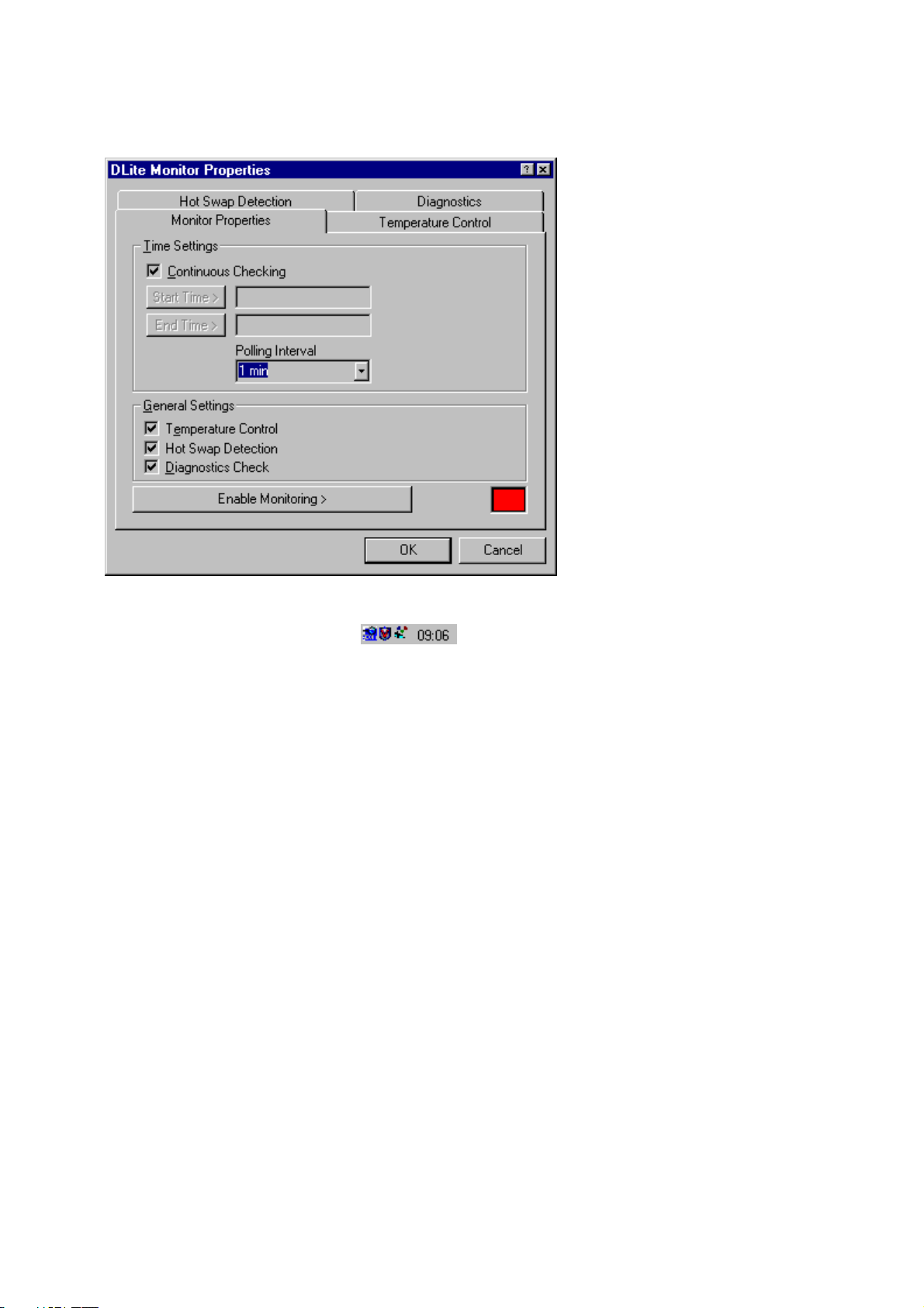
8.2.Monitoring Properties ............................. 111
Time Settings ....................................................... 111
Start Time and End Time ........................................................... 111
CALENDAR.............................................................................. 112
DATE SELECTION .................................................................. 112
TIME SELECTION ................................................................... 112
Polling Interval .......................................................................... 112
General Settings ....................................................................... 112
Remark ................................................................. 113
8.3.Hot Swap Detection ................................ 114
Introduction ..................................................................... 114
A Tile is replaced ................................................. 114
A Tile is missing .................................................. 114
8.4.Diagnostics ............................................. 116
Introduction ..................................................................... 116
continued on next page
Daylight Display Systems 5 BARCO DLite Software
Page 6

Contents continued
8.5.Temperature Control .............................. 117
Introduction ..................................................................... 117
Temperature Control ........................................... 117
Temperature Log Files ........................................ 118
Configuration File ..................................................................... 118
Logging Status ......................................................................... 118
Started Logging ........................................................................ 118
Ended Logging ......................................................................... 118
Number of loggings .................................................................. 118
Temperature Monitoring Diagnostics ............... 119
Temperature Tracking selected Tile .......................................... 119
Average Temperature each Tile ................................................ 119
Average Temperature Display .................................................. 119
Digital Contrast Tracking Display .............................................. 119
1. Temperature Tracking Selected Tile ..................................... 119
2. Average Temperature Each Tile ........................................... 120
3. Average Temperature Display ............................................... 120
4. Digital Contrast Tracking Display .......................................... 121
Remark .................................................................121
8.6.AEC Sensing ........................................... 122
Introduction ..................................................................... 122
AEC Sensing Properties ..................................... 122
Chapter 9
Trouble shooting ................................. 125
General ................................................................ 125
Initial Tile Setup / Guided setup ........................... 127
System Control ..................................................... 128
Source and Image Control ................................... 129
Devices ................................................................ 130
Monitoring ............................................................ 131
(9) IR Receiver ..................................................... 136
Rear Panel Inputs ......................................... 137
INPUT 1 (Selection 1) ..........................................137
INPUT 2 (Selection 2) ..........................................137
INPUT 3 (Selection 3) ..........................................137
INPUT 4 (Selection 4) ..........................................137
INPUT 5 (Selection 5) ..........................................138
INPUT 6 (Selection 6) ..........................................138
INPUT 7 (Selection 7) ..........................................138
INPUT 8 (Selection 8) ..........................................138
INPUT COMMUNICATION PORT ........................138
Rear Panel Outputs ...................................... 139
OUTPUT DATA ......................................................139
OUTPUT SDI ......................................................... 139
OUTPUT RGBHV .................................................. 139
OUTPUT AUDIO ................................................... 139
OUTPUT COMMUNICATION PORT .................... 139
POWER ................................................................. 139
Remote Control ............................................ 141
Power Up/Down ............................................ 142
AC Power (Mains) Cord Connections ............... 142
Switching ON/OFF ............................................... 142
Switching to Stand-by/Operation ...................... 142
Overview Menu Structure ............................ 143
Chapter 10
Digitizer ................................................ 133
Operation .............................................................133
SERVICE SAFETY PRECAUTIONS .............. 133
WARNING ....................................................................... 133
VENTILATION ................................................................. 133
POWER REQUIREMENTS .................................. 133
FEDERAL COMMUNICATION COMMISSION ....133
Notice on Owner's manual .................................134
Notice on Safety .................................................. 134
On safety .............................................................. 134
Notice on installation .......................................... 134
Notice on servicing ............................................. 135
Notice on cleaning .............................................. 135
Front Panel Description ............................... 136
(1) LCD Screen ..................................................... 136
(2) Menu Arrows .................................................. 136
(3) ENTER ............................................................. 136
(4) Exit................................................................... 136
(5) Adjust .............................................................. 136
(6) Video Adjustments......................................... 136
(7) Direct Source Selection ................................ 136
(8) Power/Stand-by .............................................. 136
Daylight Display Systems 6 BARCO DLite Software
Page 7
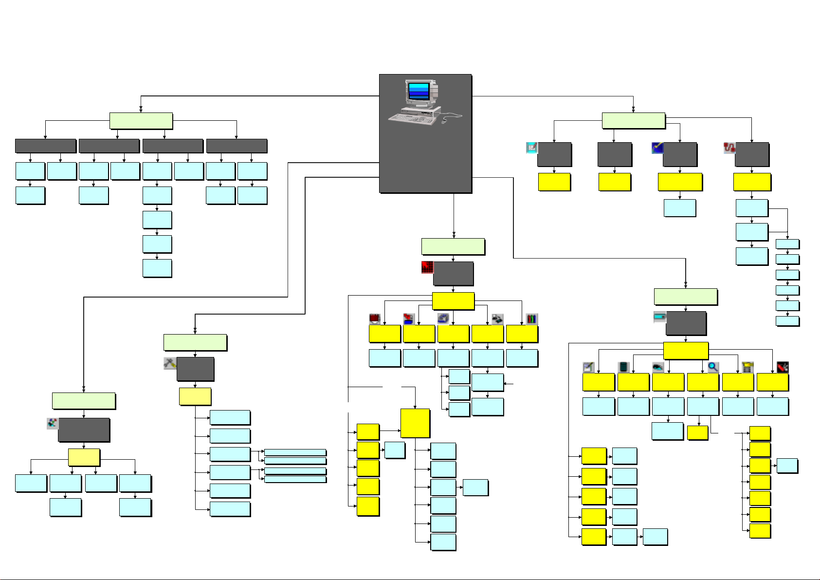
Block Diagram DLite Control Software
DLit e System
Control
Software
Chapter 6
Chapter 3/4
Chapter 4
Chapter 7
Chapter 8
Chapter 5
Visualisation
Correction
Correction
Calibration
DLite Source and
Image Control
DLite Display
Setting
Setting
Sources
Save a DLite Configuration to File >
Download Tile Database >
Menu Structure
Software Overview
File Options SetUp
Communication
SetUp...
Communication
Settings
Operation Properties Guided SetUp
Exit
Work Off Line
Dlite System
Monitor Properties
Dlite Monitor
Properties
Monitor Properties
Temperature
Control
Temperature
Logging
Hot Swap
Detection
Diagnostics
AEC sensing
DLite Display
Configuration
DLite Display
Configuration
Storage
DLite Display
Auto Addressing
DLite Display
Configuration Info
Check For
Devices
Initial Tile
Setup
DLite Display
SetUp
Help
About the DLite
Control Software
Tile Addressing
Tile Positioning
DLite Display
Configuration Files
DLite Display
Actions
DLite Display
Progress Info
DLite Display
Resolu tion Info
Help
Control Software
Help Topics
DLite System
Help
< Load a DLite Configuration from File
Download Tile Configuration >
Select a Tile then Click
on Right Mouse Button
Version 1.04
Global Access Configuration Data Base
Access
Tile
Diagnose
Tile
Enable
Tile
Disable
Tile
Exclude
from
Global LED Wall
Access
Double Click
on a Tile
Diagnostics
Tile [ ]
LED Wall
Configuration
Individual Til e
Control
DLite System
Control
DLite Display
Data Managemant
Visual Mask
Control
Visual LED
Control
3D
Correction
Tile Properties
Definative
Chroma
Individual
Correction
General
Settings
Croma
Management
Temporary
Chroma
Flash Update Calibration
Flash Update
Wizard
Flash Update
Options
Flash Update
Processing
Visual LED
Control
DLite Di s pl a y
Calibration
Load HEX
Windowing
Option
Windowing
Option
Router Box
Router Box
Info Remote Control Imaging
Day Light Display
Digitizer Info
Add Source
Delete
Source
Import
Source
Export
Source
Edit Source
Remote Control
Source SetUp
[ ] Position the
Confirmation
Import a DLite
Display
Export a DLite
Display
Edit User
Defined
240
Ambient Environment
Daylight Display
Digitizer Imaging
Tweak Gamma
Correction
Confirmation
Ambient
Controller
Controller
Sensor Weight
AEC [ ]
DLite Source
Control
Video Scaling D3 Source Settings
Windowing
Toolbox
Fiberlink: Selected
Scaling Source
Click Right
Mouse Button
Fiberlink
Address
Pattern Generator
Transmitter
Pattern Generator
Receiver
Diagnostics of
Fiberlink
Transmit/Receive
Show
Coordinates
Show LED
Wall Mask
Show
Borders
Video
Data
Video on
Data
Data on
Video
Advanced
Advanced Settings
Visual LED
None
H Ramp
V Ramp
Crosshatch
Byte Level
Multiburst
Control
Daylight Display Systems 7 BARCO DLite Software
Page 8

Page 9
CHAPTER 1
Introduction
The DLite System Control Software is designed preliminary as a user interface to be used with BARCO
Digitizer and DLite Display in a windows environment (Windows 95/ Windows 98/ Windows NT).
The Control Software can be used to control the Barco Digitizer/DLite Display when connected through a
serial RS232 connection
Implemented Features
1.1.Introduction
The DLite System Control software resides in the Taskbar during startup, is always resident. The software is
divided in two main parts:
DLite System Control Software Dialog
This window gives the user access to ALL controls to the DLite System
Daylight Display Systems 9 BARCO DLite Software
Page 10
Chapter 1 Introduction
Monitoring
This part window resides in the Taskbar and can be accessed by clicking the right mouse
button over the icon. This part is important for monitoring the DLite System. The software keeps monitoring
(when enabled) even when the DLite System Control Software Dialog is closed.
1.2.Setup
The user can choose between the Initial Tile Setup or the Guided Setup Wizard (where the system will ask
the user, step by step to provide the necessary information).
The Setup allows the user to make the DLite Display setup in an simple manner. The user can change the
Display layout (number of rows, number of columns and the linking orientation), while the system takes care
of Automatic Addressing, Automatic Positioning and Automatic Configuration.
1.3.System Control
The control software visualizes the DLite Display in its real configuration, providing the following features:
EASY ACCESS TO ALL SETTINGS
By simply clicking on a tile, the user can access all its settings (Tile properties, general settings, chroma
adjustment, individual correction data,)
ALTER DLITE DISPLAY CONFIGURATION BY DRAG AND DROP
GLOBAL ACCESS TO THE DLITE DISPLAY WITH POSSIBILITY TO CHANGE THE CONTRAST
SETTINGS, RESOLUTION MODE,...
OVERVIEW OF THE DLITE DISPLAY CONFIGURATION WITH POSSIBILITY TO TOGGLE EASILY
BETWEEN ALL THE TILES
EMBEDDED SOFTWARE & FIRMWARE UPDATE
Daylight Display Systems 10 BARCO DLite Software
Page 11

Chapter 1 Introduction
DATABASE MANAGEMENT
CALIBRATION
INDIVIDUAL DIAGNOSTICS
VISUALIZATION OF HOT SWAP DETECTION
1.4.Source & Image Control
USER DEFINED SOURCES AND QUICK SOURCE SWITCHING
SIMULATED REMOTE CONTROL
IMAGE PROCESSING, TO IMPROVE THE IMAGE ON THE DLITE DISPLAY
SCALING: COMPRESSING AND PANNING OF THE VIDEO IMAGE
UP-SCALING
GAMMA CONTROL
1.5.Monitoring
RESIDENT TEMPERATURE CONTROL
HOT SWAP DETECTION + AUTO CALIBRATION
RESIDENT DIAGNOSTICS
Daylight Display Systems 11 BARCO DLite Software
Page 12

Page 13

CHAPTER 2
Control Software package
System Requirements
Install the Software Package on a PC with minimum 5 MB of free space available.
A minimum configuration of a 486 processor, 75 MHz and 32 MB RAM is necessary.
The minimum operating system required is a 32 bit Windows version:
- Win95 / Win98 and later versions
- Win NT.3.5. and later versions
The screen resolution of the software is suggested at 800*600 for a good working environment.
Software Installation
To install the software, put the CD-ROM in your CD-ROM drive.
From within the Windows environment go to the Start Menu. Choose Run... from the menu and proceed as
follows:
1.PUSH BROWSE
2.CHOOSE YOUR CD-ROM DRIVE
3.SELECT SETUP.EXE PRESS OPEN TO SELECT SETUP.EXE
4.PRESS OK TO RUN THE INSTALLATION
5.PRESS ENTER TO EXECUTE THE INSTALLATION PROGRAM.
6.EVERYTHING WILL BE INSTALLED AUTOMATICALLY BY THE INSTALLATION PROGRAM.
Daylight Display Systems 13 BARCO DLite Software
Page 14

Page 15
CHAPTER 3
Getting Started
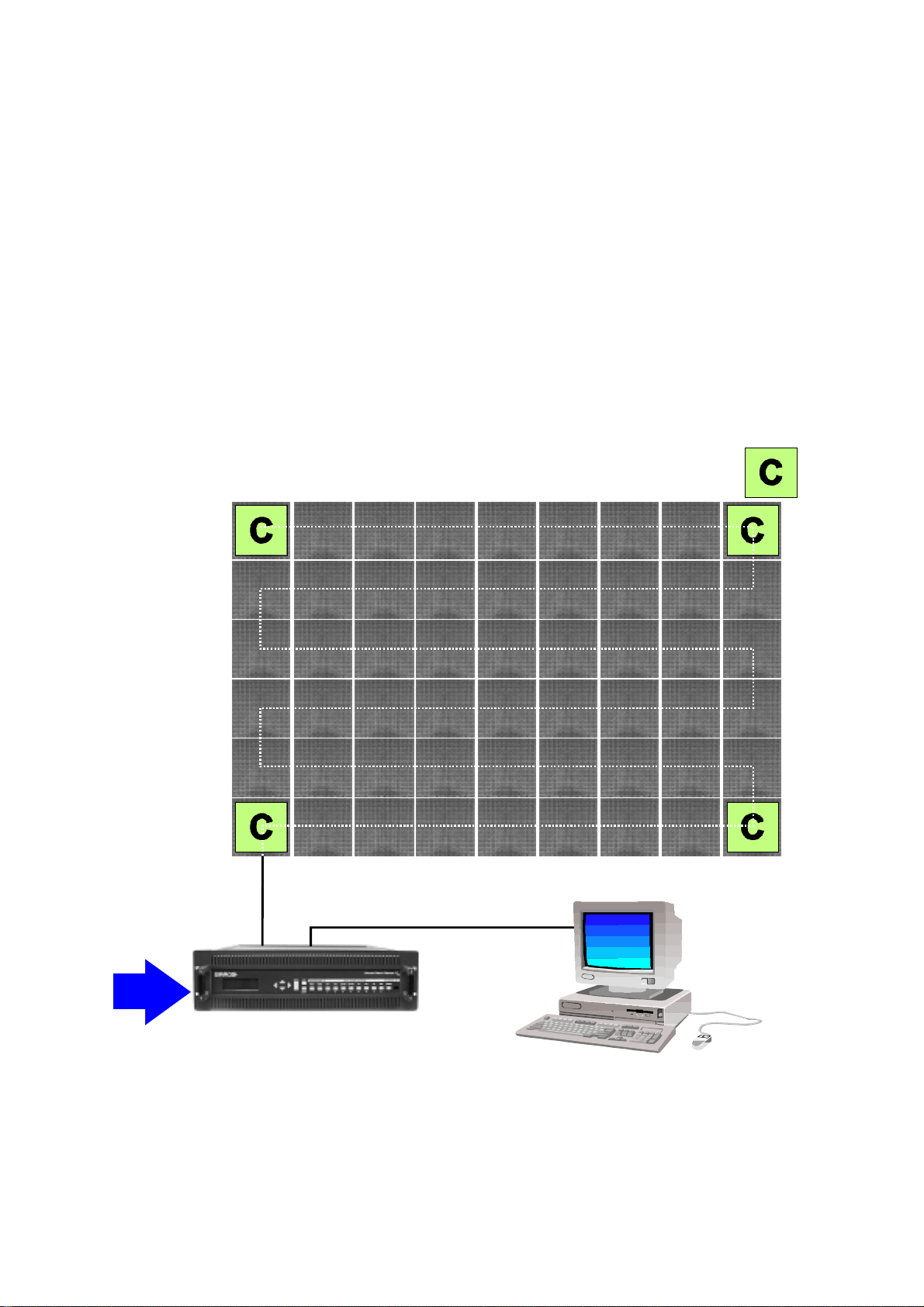
System Overview
DLite DISPLAY
DATA IN TO FIRST TILE
POSSIBLE START TILES FOR DATA CONNECTION.
MAY BE REALIZED IN THE VERTICAL OR
HORIZONTAL DIRECTIONS
RS232 IN
DATA TO DISPLAY
SOURCE
SIGNALS
RS232 OUT
DIGITIZER
CONTROL P.C.
The three main parts of the DLite Display System are: the DLite Display (that consists of different DLite
Display tiles), the Daylight Display Digitizer (that takes care of all video conversion and conditioning) and the
DLite Display Control Software (that controls the Digitizer as well as the DLite Display tiles).
Different sources can be displayed with this system: Composite Video (2x), S-VHS (2x), Component Video,
Daylight Display Systems 15 BARCO DLite Software
Page 16
Chapter 3 Getting Started
RGB, SDI and PC Data.
Its the Daylight Display Digitizer that processes all source signals for digital distribution to every DLite display
tile. The Digitizer can be accessed directly or via the DLite Display Control Software. This software is
designed as a user interface to be used with the Daylight Display Digitizer and the DLite Display and can be
used when connected to the Digitizer through a serial RS232 connection.
Getting Started with the DLite Display System
To get started with the DLite Display System act do as follows
1. MAKE SURE...
· To have the software installed properly
· To have made the proper connections between Display & Digitizer and between Digitizer & Controlling PC
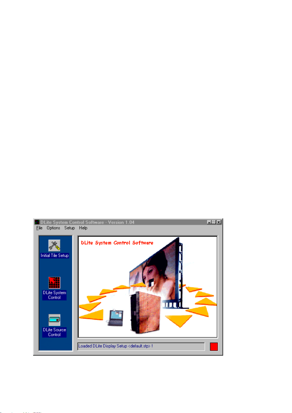
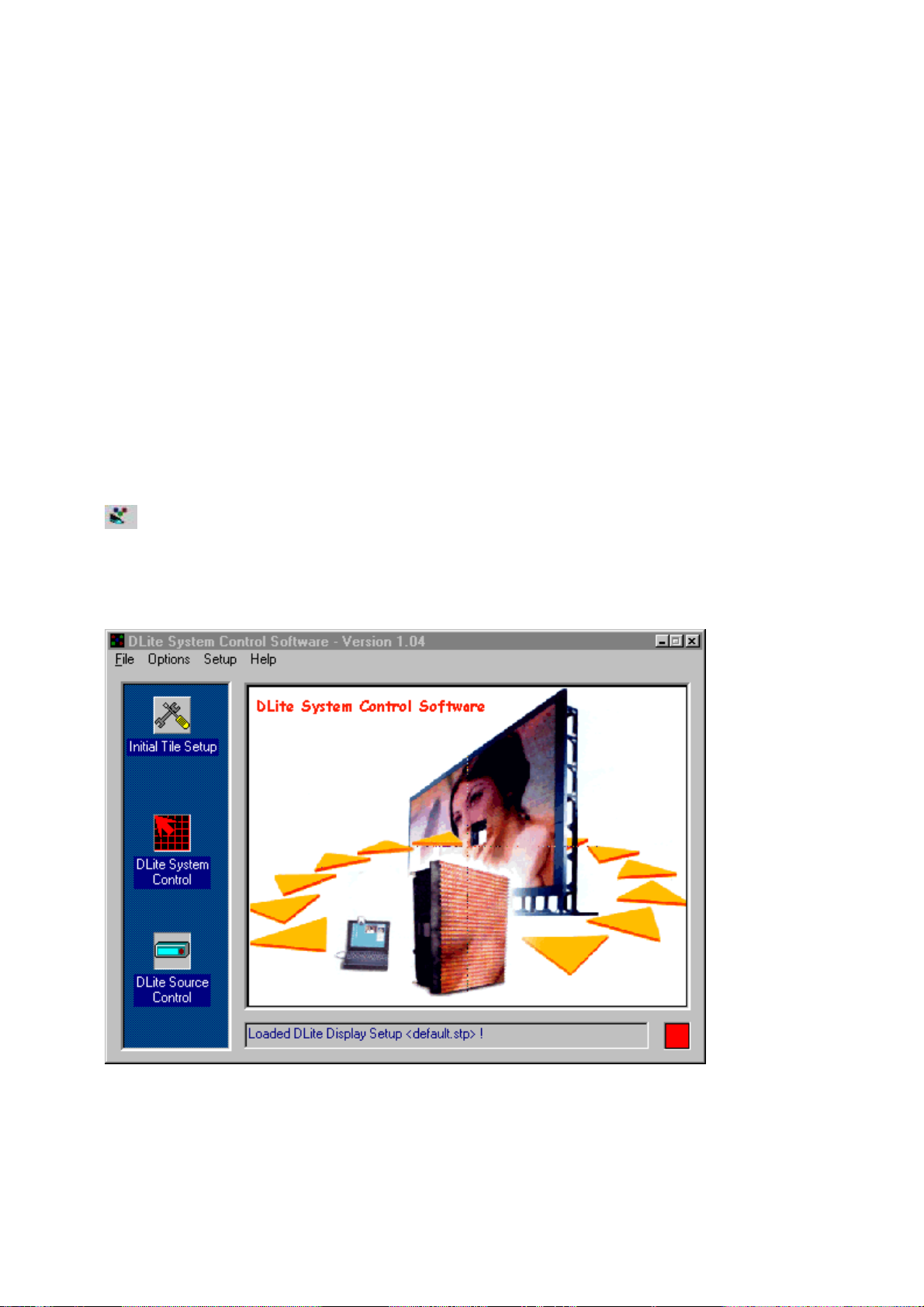
2. ACCESS FROM THE TASKBAR
When one starts up the DLite software for the first time, an icon appears in the taskbar.
This icon represents the DLite Software being resident in the Taskbar.
The DLite System Control Software Dialog also appears simultaneously.
Setting up a DLite Display Configuration and controlling the entire system is always done from the box shown
above. However, when one closes this box, this doesnt close down the software because it remains resident
in the taskbar.
Daylight Display Systems 16 BARCO DLite Software
Page 17
Chapter 3 Getting Started
REMARK
Exit the software by clicking the right mouse on the DLite Software icon and selecting <Exit> from the menu.
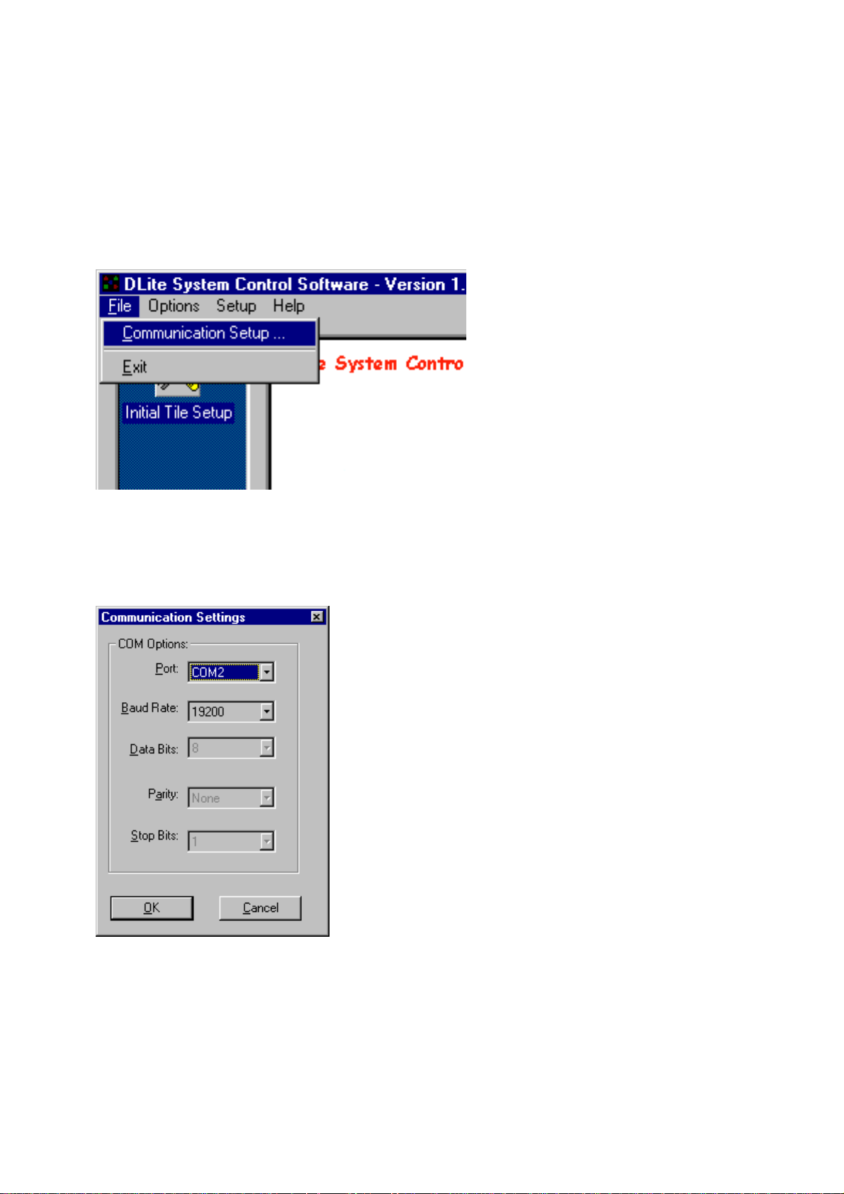
3. COMMUNICATION SETUP
Proceed as follows to change your communication settings
COMMUNICATION SETUP
From the File menu, choose Communication Setup
SETUP
The Communication Setting dialog box appears.
COMMUNICATION PORT
Change the Communication port to the serial port
Used for connecting the PC to the Digitizer.
BAUDRATE
If required, change the baudrate to match the baudrate of the digitizer.
The baudrate determines the speed of the data transfer.
Daylight Display Systems 17 BARCO DLite Software
Page 18
Chapter 3 Getting Started
OK BUTTON
Click the OK button to save changes or CANCEL to abort.
REMARKS
Other settings as the data bits, stop bits and parity are default and can not be altered
Exit the software by clicking the right mouse on the DLite Software icon and selecting <Exit> from the menu.
4. DISPLAY SETUP
Before using a DLite Display it must be initialized (addressing, positioning,...), either:
Follow the Guided Setup Wizard (started automatically when setting up a display for the first time)
or, follow the Initial Tile Setup
See Control Software SetUp
5. DEFINE SOURCES
Add user defined sources via the Source Control
See Source & Imaging Control to add sources
6. GENERAL USE
By far the most commonly used features for the DLite System will be:
IMAGING
SCALING
See Source & Imaging Control
7. MONITORING
Monitoring is available via the taskbar . Several Monitoring options are possible
MONITORING PROPERTIES
TEMPERATURE CONTROL
HOT SWAP DETECTION
DIAGNOSTICS
Daylight Display Systems 18 BARCO DLite Software
Page 19
CHAPTER 4
Control Software
Setup
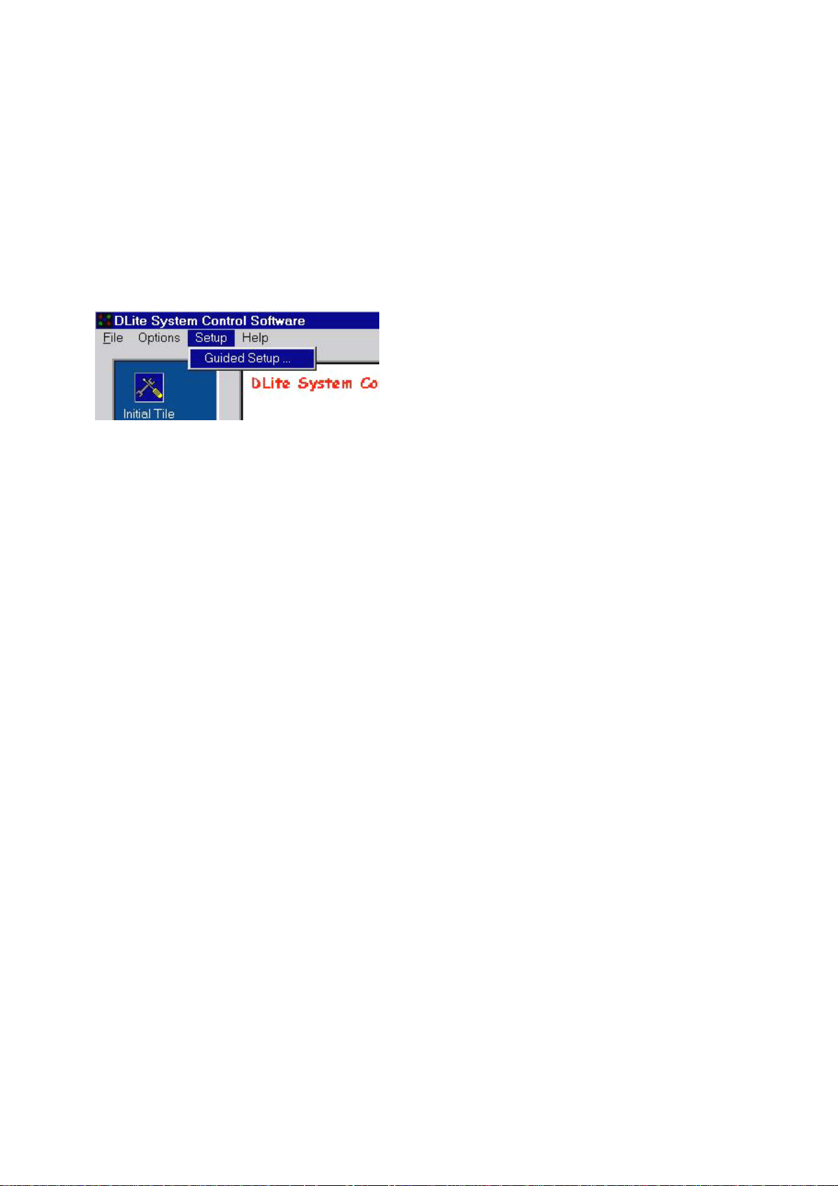
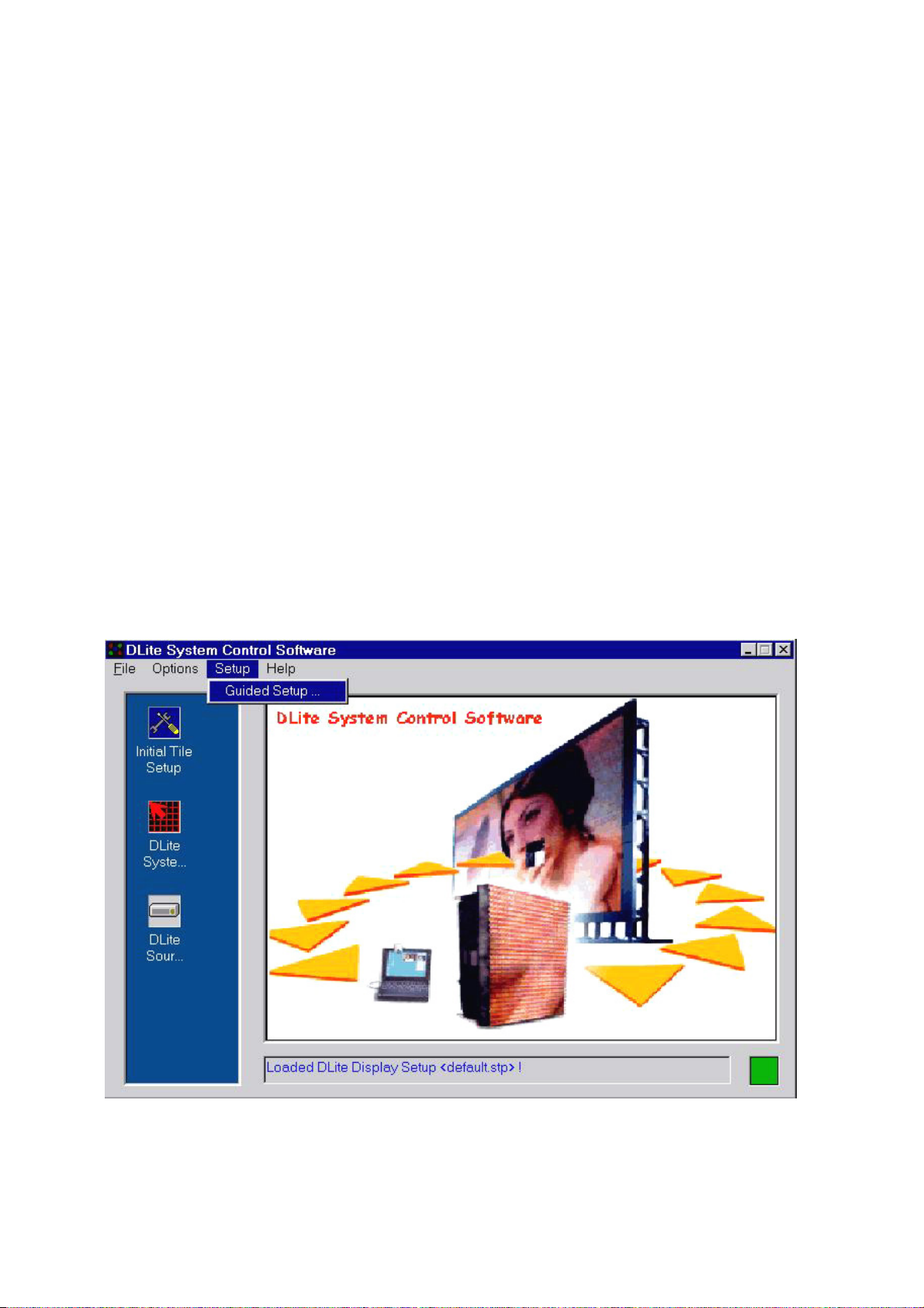
4.1.Guided Setup
Introduction
The guided setup wizard will start automatically when clicking the INITIAL TILE SETUP icon for the first
time. It guides the user through the process of setting up a DLite Display Configuration, displaying each
step the user has to take action and automating the main setup tasks. For accessing this wizard
afterwards click the GUIDED SETUP in the SETUP menu.
Daylight Display Systems 19 BARCO DLite Software
Page 20
Chapter 4 Control Software/Setup
Menu Structure
DLite System Control
Software
Version 1.04
File Options SetUp
Communication
SetUp...
Communication
Settings
Exit
Operation Properties Guided SetUp
Work Off Line
1.DISPLAY CONFIGURATION
DLite Disp lay
Configuration
DLite Disp lay
Configur ation
Storage
DLite Disp lay
Auto Addressing
DLite Disp lay
Confi guration Info
Check For
Devices
Help
About the DLite
Control Software
Help
Help Topic s
DLite System
Control Software
Help
Daylight Display Systems 20 BARCO DLite Software
Page 21
Chapter 4 Control Software/Setup
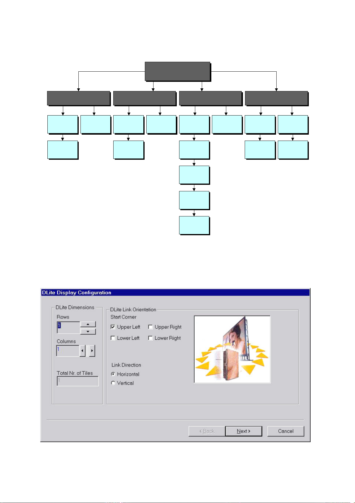
Initialize the DLite Dimensions and Link Orientation as follows
DLITE DIMENSIONS
· select the desired number of rows and columns or use the
corresponding arrows. The number of tiles will be changed automatically
DLITE LINK ORIENTATION
· select the start corner, this is the place of the first tile
(i.e. the tile connected to the Digitizer) in the display
· select the Link Direction to define the way tiles are connected to each other (H / V)
NEXT-BUTTON
Click the NEXT-button to proceed
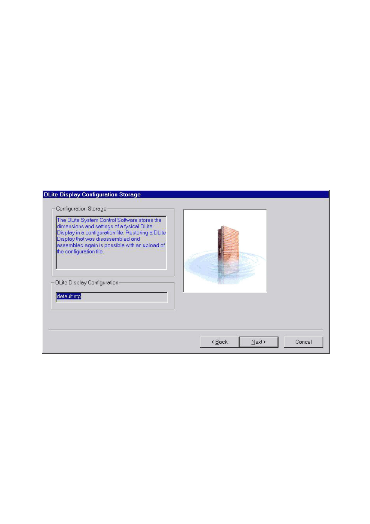
2.DISPLAY CONFIGURATION STORAGE
A configuration file stores a real configuration. For each tile it stores the address, the positioning, the
correction data for the quadrants, the chroma measurements data and some general information.
Daylight Display Systems 21 BARCO DLite Software
Page 22
Chapter 4 Control Software/Setup
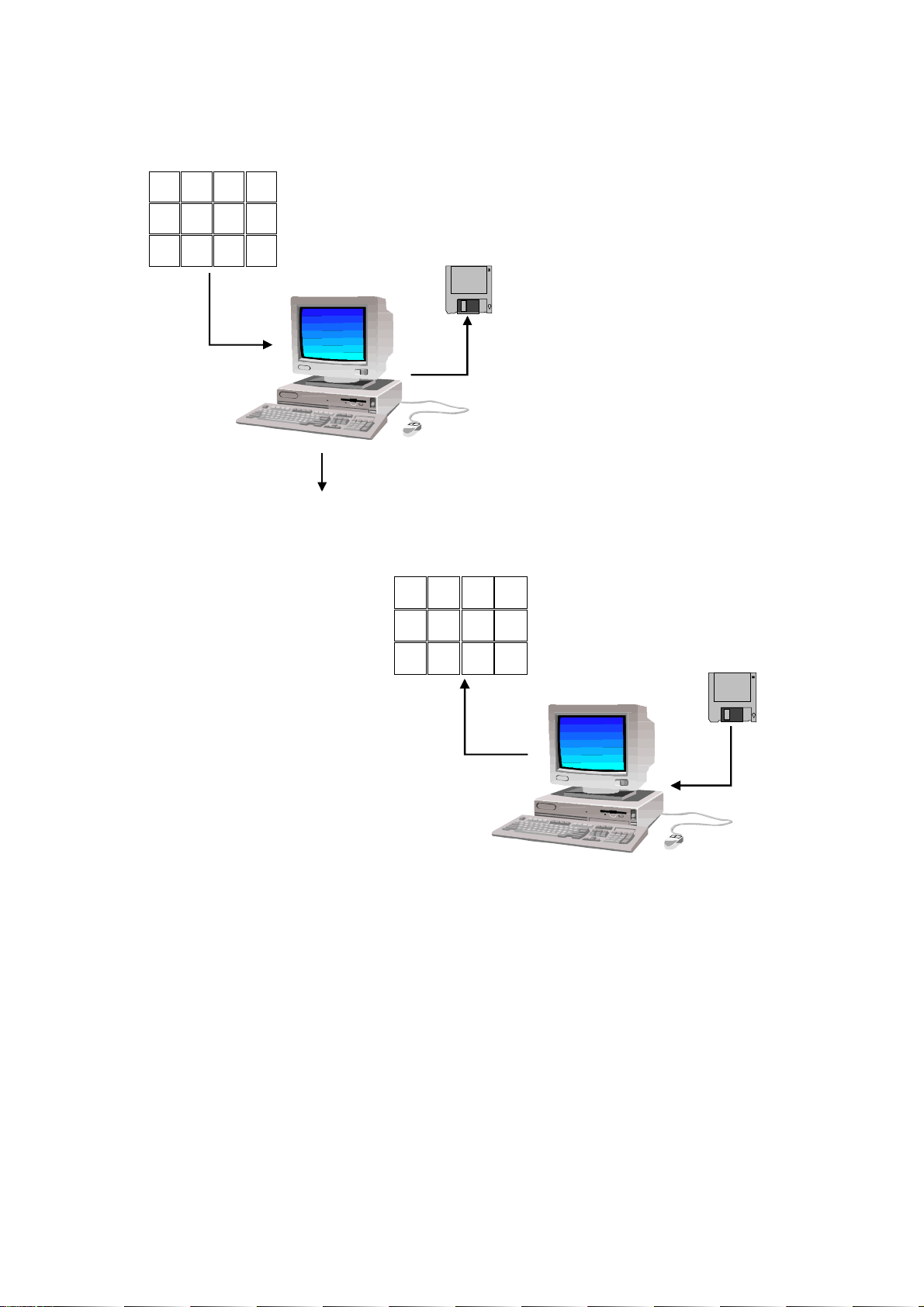
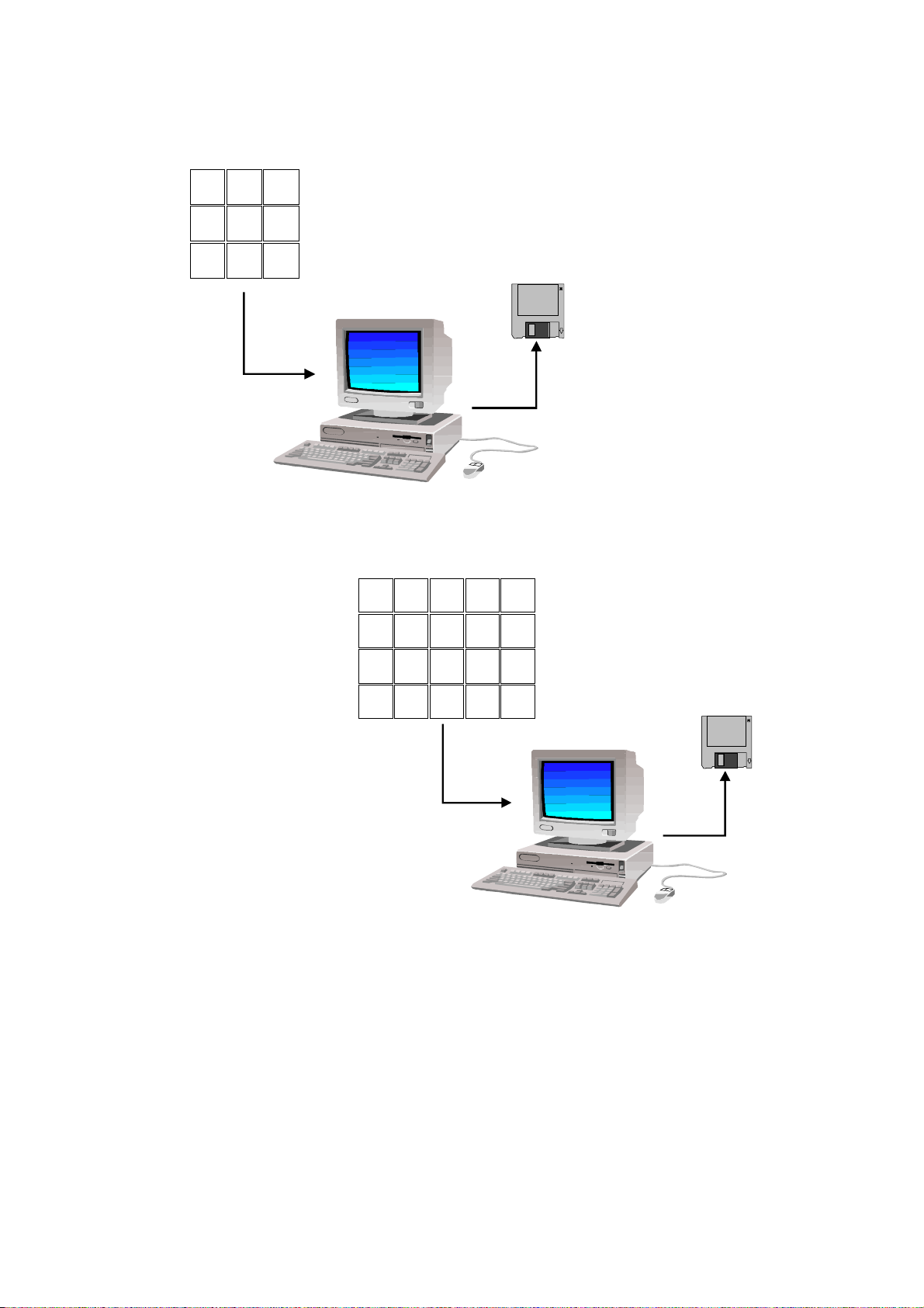
A configuration file can be useful in the following situations
· Disassembling an existing DLite Display and assembling it again (with the same dimensions and link
orientation)
9
10 11 12
8 7 6 5
1 2 3 4
down load configuration
save to disk
disassemble and assemble
9
10 11 12
8 7 6 5
1 2 3 4
display configured without
readdressing, repositioning...
ADVANTAGE: no setup needed again! (Software is already configured)
load from disk
Daylight Display Systems 22 BARCO DLite Software
Page 23
Chapter 4 Control Software/Setup
· Accessing different DLite Displays (for example with a laptop) in different locations, with different
configurations
PLACE A
down load configuration
save to disk as CfgA
PLACE B
save to disk as CfgB
down load configuration
ADVANTAGE: Once configured for a DLite Display, you can load the desired configuration to work with the
software
1. Fill in the name of the Configuration file in the DLite DISPLAY
CONFIGURATION-window (automatically displays default loaded file)
2. Click the NEXT-button to proceed
Daylight Display Systems 23 BARCO DLite Software
Page 24
Chapter 4 Control Software/Setup
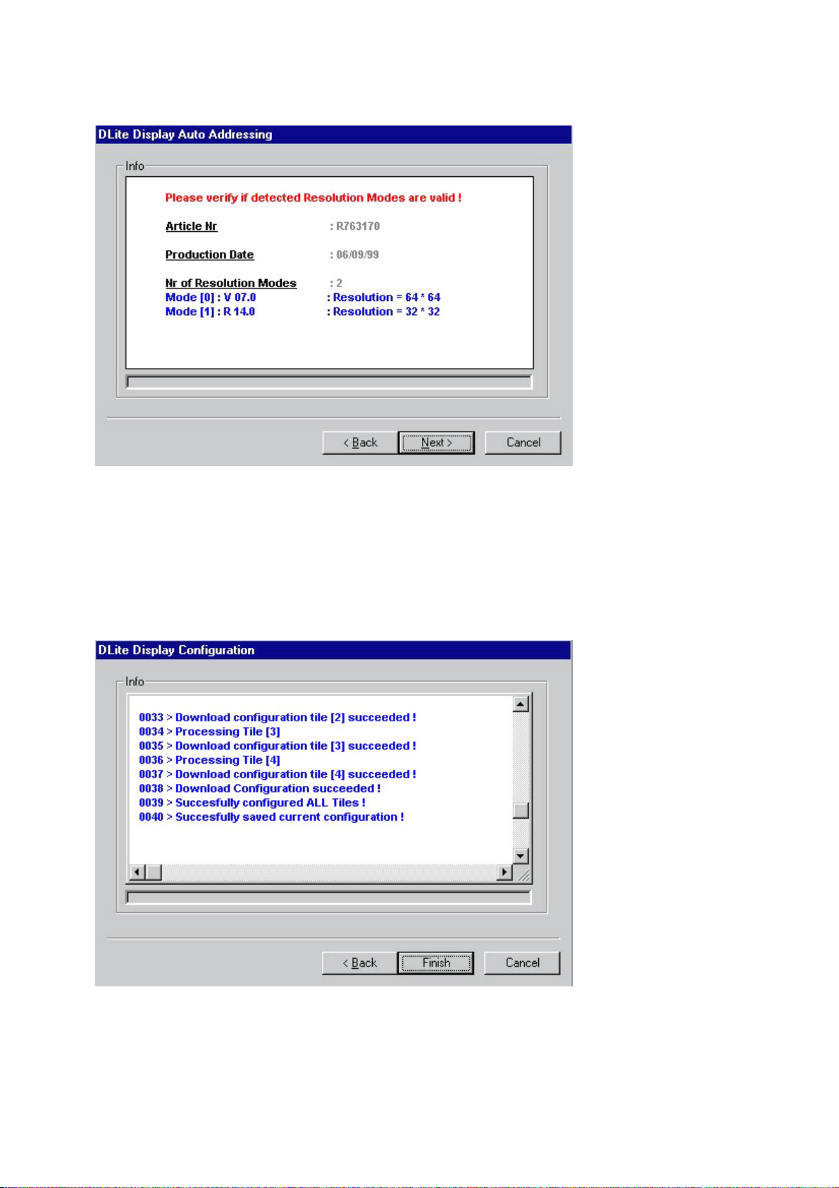
3.DISPLAY AUTO ADDRESSING
Here one can see which kind of display is used and what the possible resolution modes are. Check if the
detected resolution modes are valid. If not, click the CANCEL-button.
If everything is detected correctly, click the NEXT-button.
4.DISPLAY CONFIGURATION
The DLite Display Configuration displays the info about the progress of the configuration. Info about the
addressing of the tiles, the positioning, the database creation and the downloading of the configuration are
viewable.
When done, scroll through it using of the scrollbar or save the log by opening a popup menu with the right
mouse button.
Finish the guided setup by clicking the FINISH-button.
Daylight Display Systems 24 BARCO DLite Software
Page 25
Chapter 4 Control Software/Setup
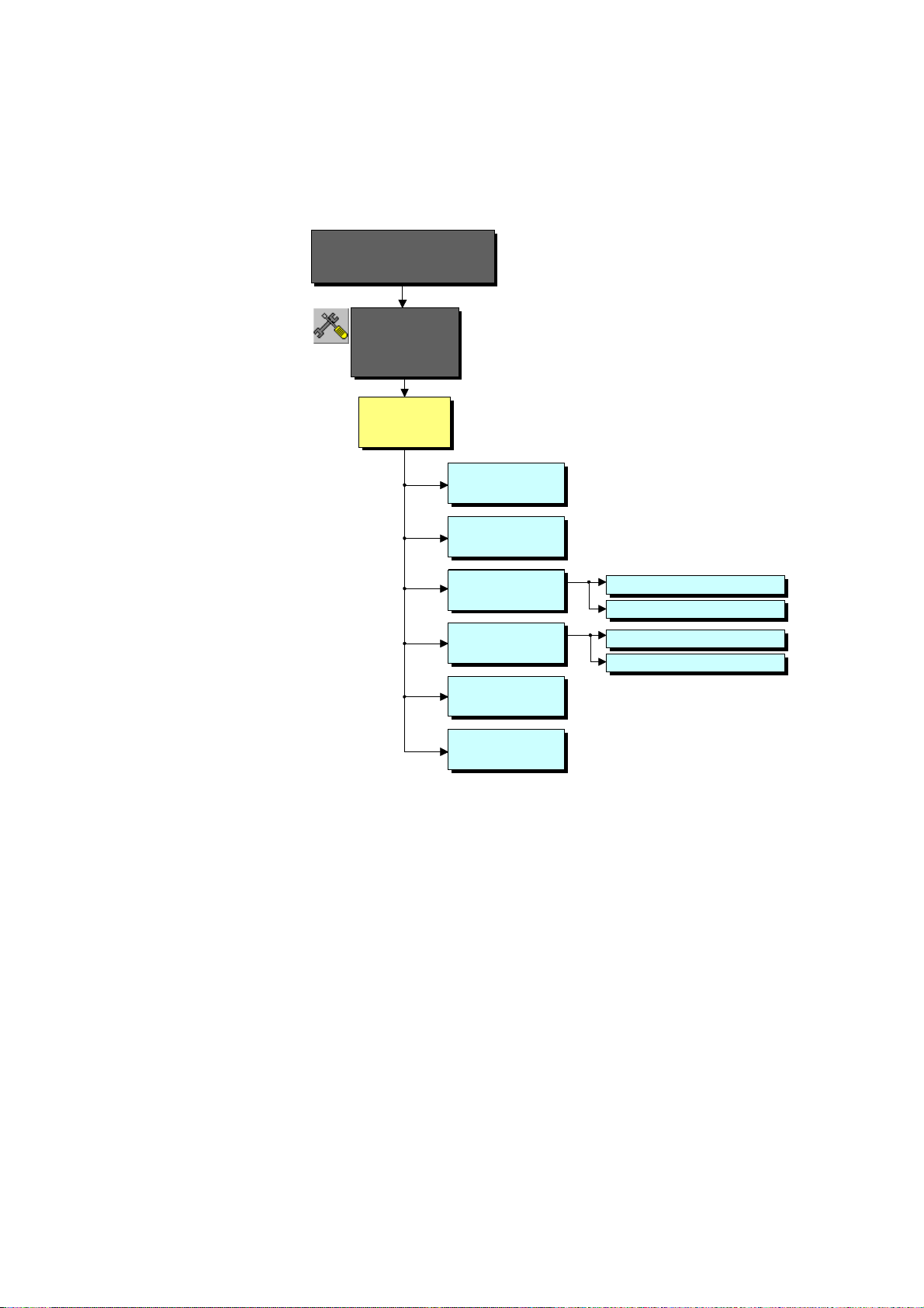
4.2.Initial Tile Setup
Menu Structure
DLite System Control
Software
Version 1.04
Initial Tile
Setup
DLite Display
SetUp
Tile Addressing
Tile Positioning
DLite Display
Configuration Files
DLite Display
Actions
DLite Display
Progress Info
DLite Display
Resolution Info
< Load a DLite Configuration from File
Save a DLite Configuration to File >
Download Tile Database >
Downl oad Tile Configuration >
(click the INITIAL TILE SETUP-icon)
When entering the initial tile setup for the first time the guided setup will be started automatically.
Otherwise the <DLite Display Setup> screen appears:
Daylight Display Systems 25 BARCO DLite Software
Page 26
Chapter 4 Control Software/Setup
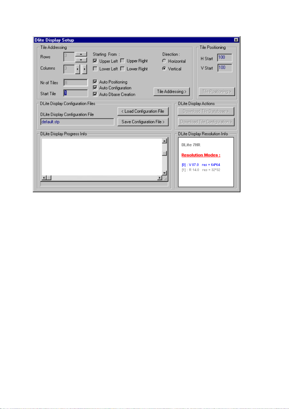
Here the DLite Display can be configured without following the guided setup wizard.
1.TILE ADDRESSING
SELECT THE DLITE DIMENSIONS
Select the desired number of rows and columns or use the
corresponding arrows. The number of tiles will be changed automatically.
Also the Start Tile can be initialized (i.e. the address of the first tile, the tile that is connected to the Digitizer).
SELECT THE LINK ORIENTATION
Select the start corner, this is the place of the first tile (i.e. the tile that is connected to the Digitizer) in the
display.
Select the Link Direction to define the way tiles are connected to each other (H / V).
AUTOMATICALLY EXECUTE TILE POSITIONING
Tile Configuration or Database Creation by selecting the corresponding check box.
TILE ADDRESSING BUTTON
Clicking this button will start giving each tile its individual address, starting with the first tile that gets the
address you chose as start-address.
The progress of the addressing is displayed in the DLite Display Progress Info-window. When done, scroll
through it using of the scrollbar or save the log by opening a popup menu with the right mouse button.
Daylight Display Systems 26 BARCO DLite Software
Page 27
Chapter 4 Control Software/Setup
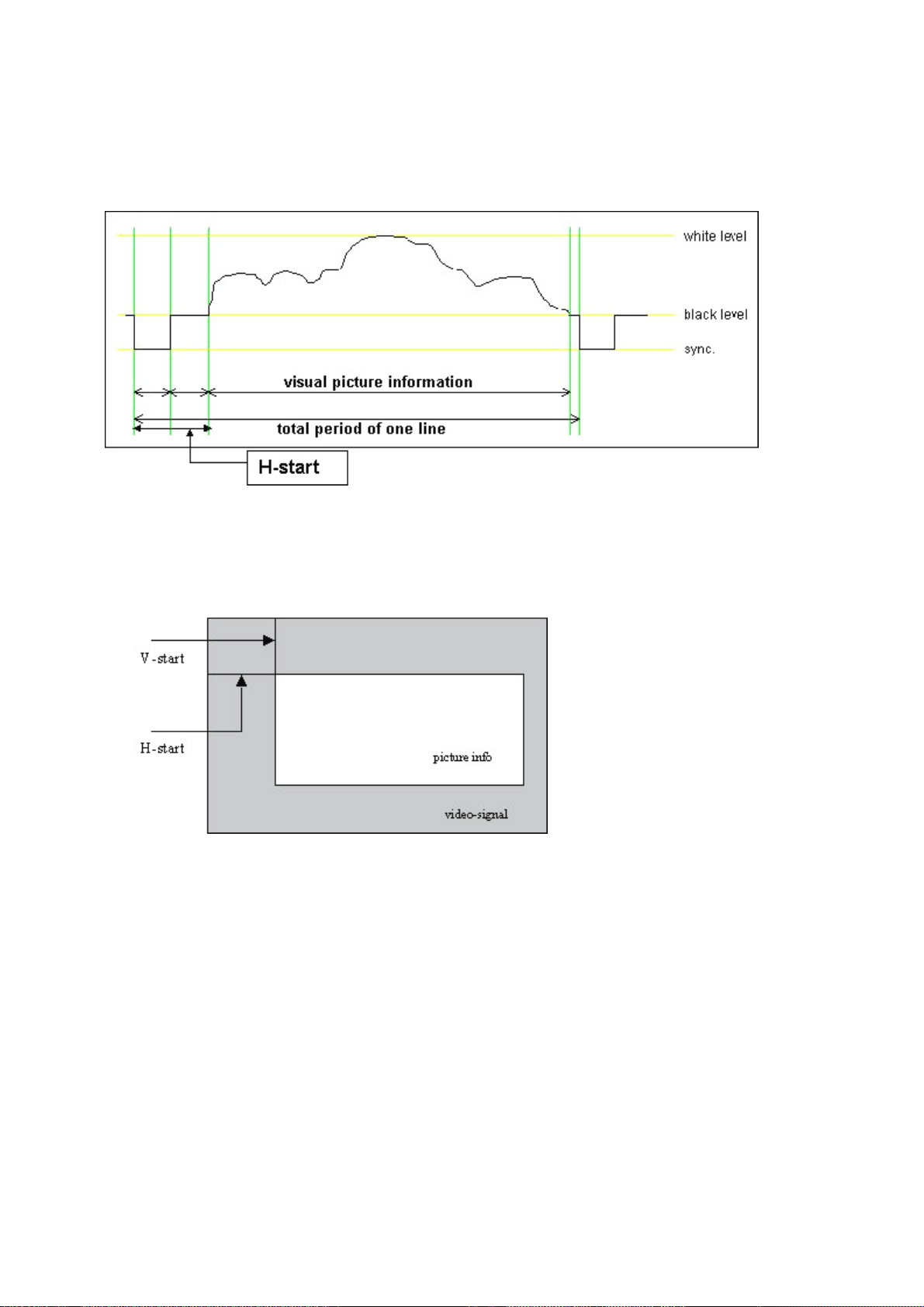
2.TILE POSITIONING
Define the horizontal and vertical start position of the incoming video. The information of one video image
consists of several video lines. On such line contains more information than only the visual picture information
(e.g. sync pulse, color burst,). The time between the start of the line and the start of the picture information
is defined as the horizontal start position.
In the same way the information of one video image contains more information than only the several video
lines. The time between the start of the image information and the first actual video line with picture
information is defined as the vertical start position.
Do as follows:
1.Select the desired horizontal and vertical start position values
2.Clicking TILE POSITIONING, gives each tile its individual position in relation to the incoming video-signal,
each tile position is calculated according to the start position.
The progress of the positioning is displayed in the DLite Display Progress Info-window. When done, scroll
through it using of the scrollbar or save the log by opening a popup menu with the right mouse button.
Daylight Display Systems 27 BARCO DLite Software
Page 28
Chapter 4 Control Software/Setup
3.DISPLAY CONFIGURATION FILES
A configuration file is the storage of the real configuration. It stores the addressing and the positioning of the
display and the Tile Configuration (i.e. the correction data for the quadrants, the chroma measurements data
and some general info for each tile separately).
Saving of such a configuration file can be interesting when disassembling a configuration; when assembling it
again the system doesnt have to collect all the information from the tiles again, but can load it from the
configuration file.
In the DLite DISPLAY CONFIGURATION FILE-window one can read the last loaded configuration file.
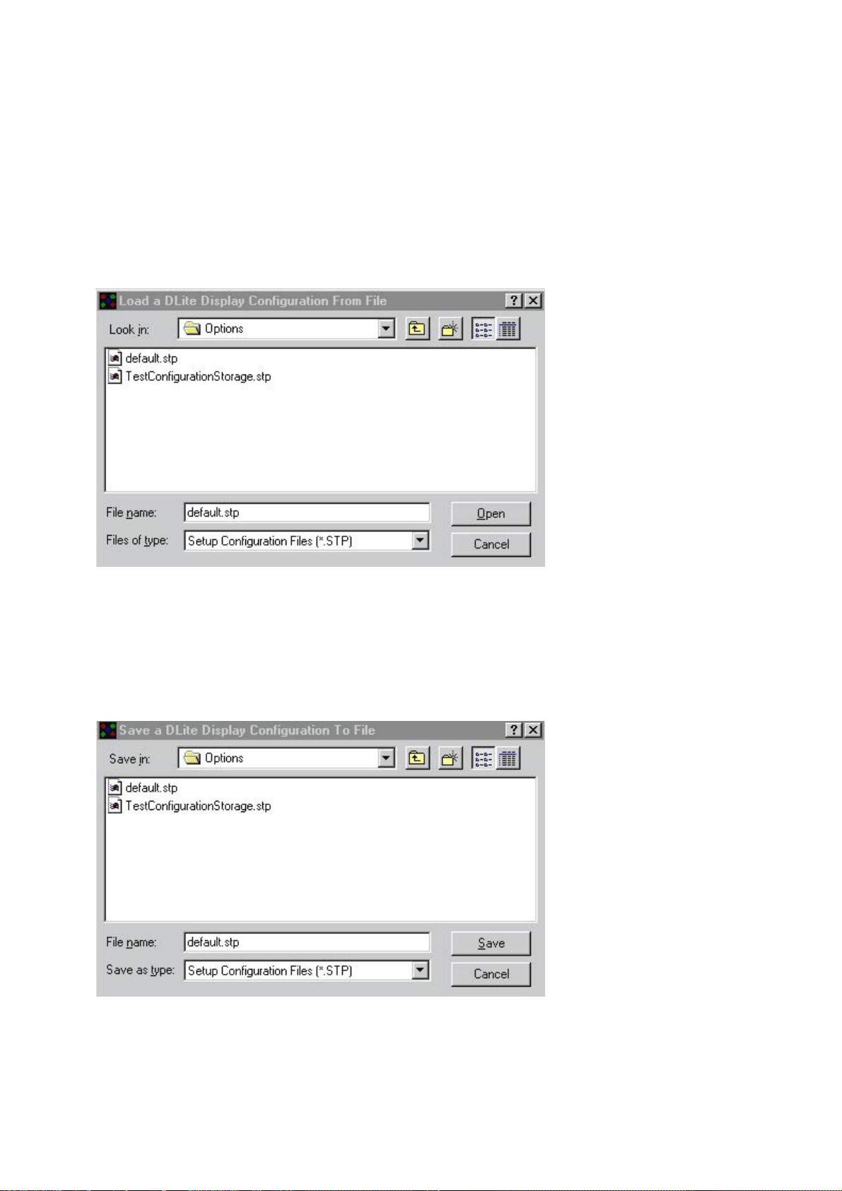
For loading a previous configuration file act as follows
1.Click LOAD FROM DISK to enter the following screen
2.Select the configuration file to open or fill in the name in the FILE NAME-screen.
3.Click OPEN
For saving the actual configuration file do as follows:
1.Click SAVE FROM DISK to enter the following screen
2.Select the configuration file to save (then this file will be overwritten) or fill in a new file name in the FILE
NAME screen.
3.Click SAVE.
Daylight Display Systems 28 BARCO DLite Software
Page 29
Chapter 4 Control Software/Setup
4.DISPLAY ACTIONS
Downloads information about the tiles in the actual display.
DOWNLOAD TILE CONFIGURATION
Downloads the Tile Configuration, i.e. the correction data for each quadrant, the chroma measurement data
and general info for each tile separately. The actual Configuration File (the file seen in the DLite Display
Configuration File window) will be overwritten with this information. To store this information on disk, follow the
instructions to save a configuration file to disk.
DOWNLOAD TILE DATABASE
Download the Tile Database, which stores the Correction Data for every single LED of a tile. This information
is stored in a file for each tile separately which is linked to the tiles serial number. One can manipulate this
database afterwards in the DATABASE MANAGEMENT of the DLite SYSTEM CONTROL.
The progress of the downloading is displayed in the DLite Display Progress Info window. When done, scroll
through it using of the scrollbar or save the log by opening a popup menu with the right mouse button.
5.DISPLAY RESOLUTION INFORMATION
This shows the possible Resolution Modes and which Resolution Mode is active. The active resolution mode
is colored blue. The DLite Display is identified in gray.
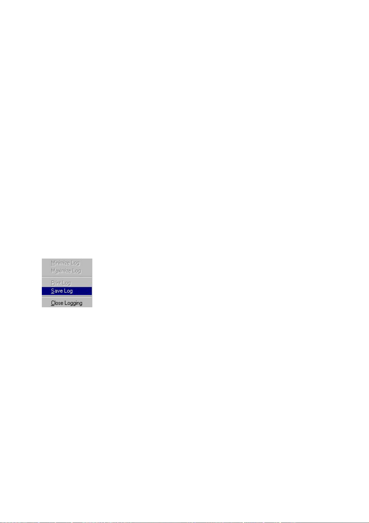
6.DISPLAY PROGRESS INFORMATION
Shows the progress of the communication when executing an action. Afterwards one can scroll through it by
use of the scrollbar.
By clicking the right mouse button the following popup menu appears
<Save Log> saves the log to a file
<Print Log> prints
Daylight Display Systems 29 BARCO DLite Software
Page 30

Page 31

CHAPTER 5
Control Software
System Control
5.1.Introduction
Introduction
Accessing the DLite System Control visualizes the DLite Display- tiles in their real configuration. From here its
easy to access a single tile by double clicking it with the left mouse button or one can get a global access to
the DLite Display. Its also possible to alter the DLite Display configuration by simply drag and drop.
Daylight Display Systems 31 BARCO DLite Software
Page 32

Chapter 5 Control Software/System Control
Visual Mask
Double Click
Correction
Correction
Calibration
Diagnostics
Menu Structure
DLite System Control
Software
Version 1.04
DLite System
Control
DLite Display
Visualisation
Select a Tile then Click
on Right Mouse Button
Access
Diagnose
Enable
Disable
Exclude
Global Access Configuration Data Base
Global LED Wall
Access
on a Tile
LED Wall
Confi guration
Data Managemant
Individual Tile
Control
Tile
Tile
Tile
Tile
from
Tile [ ]
Tile Pr operties
Definat ive
Chroma
Individual
Correction
General
Settings
Control
Visual LED
Control
3D
Correction
Flash Update Calibration
Flash Update
Wizard
Flash Update
Options
Flash Update
Processing
Visual LED
Control
DLite Display
Calibration
Load HEX
Croma
Management
Temporary
Chroma
(click the DLite SYSTEM CONTROL-icon)
Daylight Display Systems 32 BARCO DLite Software
Page 33

Chapter 5 Control Software/System Control
The icons underneath the visualization of the DLite Display provide features that influence the complete Display.
These features are:
1.GLOBAL ACCESS
For accessing all tiles at once
2.CONFIGURATION
For having an overview of the DLite Display configuration
3.DATABASE
For accessing the database
4.FLASH UPDATE
For updating the flash memory of tiles, AEC and Fiberlink
5.CALIBRATION
To calibrate a range of tiles
Double clicking a tile provides features that influence only the selected tile.
These features are:
1.TILE PROPERTIES
For having an overview of the tiles properties
2.DEFINITIVE CHROMA CORRECTION DATA
For changing the chroma data correction values definitive
3.INDIVIDUAL CORRECTION
For having access to the individual LEDs of the tile
4.GENERAL SETTINGS
For changing the general settings of the tile
5.CHROMA MEASUREMENTS
Gives an overview of the measured chroma values of the tile
6.TEMPORARY CHROMA CORRECTION DATA
For changing the chroma data correction values temporary
Daylight Display Systems 33 BARCO DLite Software
Page 34

Chapter 5 Control Software/System Control
5.2.Alter Configuration
It is possible to simply change the configuration of the DLite Display by clicking on a tile, dragging and
dropping it on another one. The addresses and corresponding files of both tiles will be switched
Daylight Display Systems 34 BARCO DLite Software
Page 35

Chapter 5 Control Software/System Control
5.3.Tile Accessing/Enabling
Clicking on a tile with the right mouse button opens the following pop up menu, where its possible to Access
the tile or to Enable/Disable the (monitoring of the) tile:
1.ACCESS TILE
Access all the tiles properties and settings. See Individual Tile Control.
2.DIAGNOSE TILE
Diagnosing a tile id done in the following window, supply voltages for all colors, link voltage and errors are
displayed
The following error messages can appear in the Diagnostic listing:
1. Fan fail detection
2. Altera Configuration Status
3. I2C errors
4. LED boards dont match
5. Error during Flash Update
plus further updated errors are possible....
Daylight Display Systems 35 BARCO DLite Software
Page 36

Chapter 5 Control Software/System Control
3.ENABLE/DISABLE TILE
Enable or disable a tile.
A tile is disabled when DISABLED appears in the tile:
4.EXCLUDE FROM CALIBRATION
Excludes the selected tile in the calculation for calibration. The tile will not influence the calibration of the wall
in any way.
When a tile is excluded, the tile appears as:
Multiple tiles can be excluded and the exclusion is saved within the current configuration until selecting the tile
and clicking <Exclude from Calibration>
Daylight Display Systems 36 BARCO DLite Software
Page 37

Chapter 5 Control Software/System Control
5.4.Individual Tile Control
Introduction
INDIVIDUAL TILE CONTROL
(double click on a tile with the left mouse button)
Double clicking the left mouse button on a tile gives access to all the tiles properties and settings. Switch
between the different topics by clicking on the corresponding header.
Features:
· Tile Properties
· General Settings
· Temporary Chroma Correction
· Definitive Chroma Correction
· Individual Correction
· Chroma Measurement
Daylight Display Systems 37 BARCO DLite Software
Page 38

Chapter 5 Control Software/System Control
1.Tile Properties
ADDRESS
The tiles address, each tile is addressed individually
SERIAL NUMBER
A tiles serial number, each tile has its own Serial Number.
SOFTWARE IDENTIFICATION
The version of embedded software a tile uses.
FIRMWARE IDENTIFICATION
The version of Firmware a tile uses.
TEMPERATURE
The temperature of an tile.
RUNTIME
The tiles time in use.
Pushing <Update Configuration> updates the configuration for the selected tile
Daylight Display Systems 38 BARCO DLite Software
Page 39

Chapter 5 Control Software/System Control
2.General Settings
WINDOW POSITIONING
1. Read the actual window positioning by clicking the READ POSITION command button.
2. Change the positioning of the tile (horizontal and vertical start and end position) by typing the desired values
in the corresponding boxes.
3. For actually changing the tiles window positioning, send these changed values to the tile by clicking the
SEND POSITION command button.
GENERAL
1. Read the actual ma_clock and PWM repeat by clicking the READ CLOCK command button.
2. Change the ma_clock and the PWM repeat by typing the desired values in the corresponding boxes.
3. Send these values to the tile by clicking the SEND CLOCK command button.
4. Put the tile in internal or external mode by choosing the desired mode and send it to the tile by clicking the
SEND MODE command button
Daylight Display Systems 39 BARCO DLite Software
Page 40

Chapter 5 Control Software/System Control
3.Temporary Chroma Correction
TEMPORARY CHROMA CORR. DATA
Overview of the chroma correction data of the tile. These correction data are used to adjust the slight colordifferences between the four quadrants of a tile.
For each quadrant and for each color one can see the correction data.
1. Read the actual data by clicking the READ button of the desired quadrant.
2. If necessary change the data.
3. Update the tile by clicking the corresponding SEND button.
Changing the data this will be temporary, so the changes will be lost when turning off this tile, for changing the
data definitive, use the Definitive Chroma Correction Data menu.
CONTRAST
The analog contrast.
1. Read the actual contrast by clicking the READ button.
2. After possibly changing these values, update the tile by clicking the SEND button.
Daylight Display Systems 40 BARCO DLite Software
Page 41

Chapter 5 Control Software/System Control
4.Definitive Chroma Correction
DEFINITIVE CHROMA CORR DATA.
Overview of the chroma correction data of the tile. These correction data are used to adjust the slight colordifferences between the four quadrants of a tile.
For each quadrant and for each color one can see the correction data.
1. Read the actual data by clicking the READ button of the desired quadrant.
2. If necessary change the data.
3. Update the tile by clicking the corresponding SEND button.
Changing this data will be definitive, so the data in the tile will be lost; for changing the data only temporary,
use the Temporary Chroma Correction Data menu
Daylight Display Systems 41 BARCO DLite Software
Page 42

Chapter 5 Control Software/System Control
5.Individual Correction
Access to the individual LEDs of the tile, and possibility to change their correction data.
QUADRANT SELECTION
Choose the desired quadrant by clicking on the corresponding square.
COLOR
Choose the desired color by clicking on the corresponding radio button.
VISUALIZE
Clicking the VISUAL LED CONTROL button makes the selected quadrant and color visible and makes it
possible to change its values (see Visual LED Control).
ACTIONS (DISABLED)
1. Download the correction data of the selected quadrant and color, stored in the tile, by clicking the
DOWNLOAD CORRECTION DATA-button.
2. If necessary change these values (by using the VISUAL LED CONTROL-button).
3. Update the tile with the stored values by clicking the UPLOAD CORRECTION DATA-button.
VISUAL LED CONTROL
Visual representation of stored individual led correction data.
Daylight Display Systems 42 BARCO DLite Software
Page 43

Chapter 5 Control Software/System Control
Select or deselect a single led by clicking it with the left mouse button. Clicking the right mouse button opens
a pop up menu:
SELECTION
SELECT/DESELECT ALL/CURRENT ROW/CURRENT COLUMN
Its possible to select/ deselect all LEDs or one row or column at once.
SEND TO PRINTER
Print the values of this quadrant by selecting SEND TO PRINTER.
Daylight Display Systems 43 BARCO DLite Software
Page 44

Chapter 5 Control Software/System Control
ADJUST SELECTED ADDRESSES
Fill in the desired correction data value (0-255) and by clicking the ADJUST-button all the values of the selected
LED-addresses will be adjusted (off-line, for updating the tile click the UPLOAD CORRECTION DATA-button in
the previous menu).
ACCUMULATE SELECTED ADDRESSES
Fill in the desired correction data for accumulation and by clicking the ADD-button this value will be
accumulated with all the values of the selected LED-addresses (off-line, for updating the tile click the UPLOAD
CORRECTION DATA-button in the previous menu).
Daylight Display Systems 44 BARCO DLite Software
Page 45

Chapter 5 Control Software/System Control
6.Chroma Measurements
Overview of the measured values for this tile for each quadrant.
Y-LUMINANCE
Abbreviation or symbol for luminance, the black & white information in a video signal.
x,y-COLOR COORDINATES
Color-coordinates, the color part in a video signal.
Daylight Display Systems 45 BARCO DLite Software
Page 46

Chapter 5 Control Software/System Control
Each point on the next diagram, representing a unique color, may be identified by two coordinates, x and y.
Daylight Display Systems 46 BARCO DLite Software
Page 47

Chapter 5 Control Software/System Control
5.5.Global Access
(Click the GLOBAL ACCESS-icon)
Pushing the Global Access Icon makes the Global LED Wall Access box appear
1.TEMPORARY CHROMA CORRECTION. DATA
Change the chroma correction data of all the tiles of the DLite Display. These correction data are used to adjust
the slight color-differences between the four quadrants. For each quadrant and for each color one can see the
correction data.
1. Change the data
2. Update the wall by clicking the corresponding UPDATE button.
This update will only be temporary, so the update will be lost after turning off the DLite Display.
2.CONTRAST SETTINGS
Change the Analog or Digital contrast for all tiles in the DLite Display.
1. Enter the desired values or use the slider.
2. Click the UPDATE-button.
3.LIGHT OUTPUT
Change the Light Output for all tiles in the DLite Display by using the slider in the Light Output tab
Daylight Display Systems 47 BARCO DLite Software
Page 48

Chapter 5 Control Software/System Control
4.GENERAL
Change the clock- and the PWM value of all tiles of the DLite Display.
1. Click the appropriate 50 or 60 Hz button according to the used source.
2. Enter the desired values or use the default values.
3. Click the SEND CLOCK button.
5.DISPLAY MODE
Put the wall in internal or external mode.
1. Choose the desired mode.
2. Send it to the wall by clicking the SEND MODE button.
6.RESOLUTION MODE
Select the resolution you want to use.
1. Choose the desired resolution.
2. Send it to the wall by clicking the SWITCH RESOLUTION-button.
Daylight Display Systems 48 BARCO DLite Software
Page 49

Chapter 5 Control Software/System Control
5.6.Configuration
(Click the CONFIGURATION-icon)
Overview of the configuration of the whole DLite Display. The most important information of each tile separately
is displayed and its easy to switch from one tile to another.
1.QUICK TILE VIEW
Overview of one tile. Switch to another tile by use of the arrows of the TOGGLE CURRENT TILE VIEW in the
OPTIONS box.
POSITION
The actual positioning: the horizontal and vertical start position (upper left corner) and the horizontal and vertical
end position (the lower right corner).
GENERAL
The tile its serial number and its actual address.
Version of embedded software (SOFT ID) and firmware (FIRMWARE ID) its using.
Mode (internal or external) the tile is working in.
PICTURE
The analog contrast values and an overview of the chroma correction data. These correction data are used to
adjust the slight color-differences between the four quadrants of a tile. For each quadrant and for each color one
can see the temporary and the definitive correction data. The temporary data values are the ones that will be
lost when turning of the tile, the definitive ones are the ones that are stored.
Daylight Display Systems 49 BARCO DLite Software
Page 50

Chapter 5 Control Software/System Control
CHROMA MEASUREMENTS DATA
The measured values for this tile for each quadrant. For each color one can see the Y (intensity) and x-, y(color coordinates) values.
2.CONFIGURATION FILE
The configuration file that is actually used.
LOAD CONFIGURATION FILE
Load a saved configuration as follows:
When loading a configuration file make sure the file is related to the actual DLite Display. If not errors will occur.
1. Click the LOAD CONFIGURATION FILE- button to enter the following screen:
2. Select the configuration file to open or fill in the file name in the FILE NAME- screen
3. Click the OPEN-button, a new configuration will be loaded.
SAVE CONFIGURATION FILE
Saving the actual configuration:
1. Click the SAVE CONFIGURATION FILE-button to enter the following screen:
Daylight Display Systems 50 BARCO DLite Software
Page 51

Chapter 5 Control Software/System Control
2. Select the configuration file to save (then this file will be overwritten) or fill in a new file name in the FILE
NAME- screen
3. Click the SAVE-button.
3.CONTROL CONFIGURATION
DOWNLOAD CONFIGURATION<
Download the actual running configuration of the DLite Display by clicking the DOWNLOAD CONFIGURATION
button.
UPLOAD CONFIGURATION>
Upload the DLite Display with the configuration youre watching by clicking the UPLOAD CONFIGURATION
button.
4.OPTIONS
CONVERT TO TEXT
Convert this configuration to a text-file by clicking the CONVERT TO TEXT-button. Choose to convert only the
configuration of the current tile or to convert all tiles by choosing the corresponding radio button.
PRINT TILE VIEW
Print the configuration of the current tile by clicking the PRINT TILE VIEW-button.
TOGGLE CURRENT TILE VIEW
Toggle from one tile to another by using the arrows of the TOGGLE CURRENT TILE VIEW-command.
Daylight Display Systems 51 BARCO DLite Software
Page 52

Chapter 5 Control Software/System Control
5.7.Database
(click the DATABASE-icon)
All procedures only influence the data stored in the files and not the data of the related tiles, except for the INIT
TILE> TARGET TILES-button and the FILES> TARGET TILES-button in the DATABASE MANAGEMENTwindow.
Access to the database of the DLite Display. This database contains all the individual correction data of all the
tiles of the DLite Display, and can be created during Setup. The information of each tile is stored in a separate
file and linked to its serial number.
1.CURRENT TILES
All the current tiles of the DLite Display, their serial number and their address.
INITIAL TILE>
Choose one tile to be the initial tile. The initial tile can be used to make adjustments on only one tile until
satisfaction with the result. Adjust all other (target) tiles with the same values as this initial tile, this by use of
the INIT TILE> TARGET TILES-button.
To select a tile as init tile act as follows:
1.Click the desired tile in the CURRENT TILES-window
2.Click the INIT TILE-button.
2.TARGET TILES
These are the tiles on which adjustments will be made. To add a tile to the target tiles do the following:
1. Click the desired tile in the CURRENT TILES-window
2. Click the ADD-button
And for removing a tile from the target tiles:
1. Click the desired tile in the TARGET TILES-window
2. Click the DEL-button
Daylight Display Systems 52 BARCO DLite Software
Page 53

Chapter 5 Control Software/System Control
3.VIEW
Access to the individual LEDs of a tile and possibility to change their correction data. For using this view
function follow the next steps:
1. Choose a tile by clicking the desired tile. This can be done in the CURRENT TILES-window, as well as in the
TARGET TILES-window or the database information window below.
2. Choose the quadrant to view by clicking the corresponding square.
3. Choose the desired color by clicking the corresponding radio button.
4. Click the VIEW-button.
5. If necessary, adjust the values as explained in Individual Tile Control - Individual Correction - Visual Led
Control
6. After possible adjustments the system will ask to store those new values in the file (Click YES for saving
them)
4.MASK
With this function its possible to create a mask to put over all the target tiles. When applying this mask the
correction values of all LEDs of the selected quadrant and color of all target tiles will be accumulated (or
subtracted) with the values of the corresponding LEDs of the mask. For applying this act as follow:
1. Choose the desired quadrant by clicking the corresponding square in the VIEW-window.
2. Click the VIEW MASK-button.
3. Adjust the mask in the same way as explained in Individual Tile Control - Individual Correction - Visual LED
Control
4. After adjusting the mask the system will ask to store those new values in the mask file (Click YES for saving
them)
5. Choose to accumulate the mask values or subtract them by choosing the POSITIVE-, respectively
NEGATIVE-radio button.
6. Click the APPLY MASK-button
5.DATABASE MANAGEMENT
1.INITIALIZE TILES
INIT TILE> TARGET TILES
This function will influence the tiles and not their files!
By clicking this button all the values of the target tiles will be overwritten with that of the init tile. Because this
action is definitive the system will ask to confirm to do this:
Daylight Display Systems 53 BARCO DLite Software
Page 54

Chapter 5 Control Software/System Control
After clicking YES the action proceeds.
INITIALIZE INIT TILE WITH VALUE
Click this button to give the tile selected as init tile an initial value. All the LEDs of this tile will get this value as
correction data. Because this action is definitive the system will ask to confirm to do this:
After clicking YES the action will proceed with the following screen where one can select the desired initial
value:
2.UPDATE LED WALL TILES
This function will influence the tiles and not their files!
By clicking the FILES> TARGET TILES-button all the data stored in the tiles selected as target will be
overwritten with the data in their related files. Because this action is definitive the system will ask to confirm to
do this:
After clicking YES the action proceeds.
3.UPDATE DATABASE FILES
By clicking the TARGET TILES> FILES-button all the data in the files selected as target will be overwritten with
the data stored in the tiles. Because this action is definitive the system will ask to confirm to do this:
Daylight Display Systems 54 BARCO DLite Software
Page 55

Chapter 5 Control Software/System Control
After clicking YES the action proceeds.
4.ZIP MANAGEMENT
This function gives the possibility to make a back up of the database. This can be very interesting; when some
or all information in the tiles is lost, it can be repaired.
For making this back up file do the following:
PACK DATABASE FILES
Click the PACK DATABASE FILES-button to enter the following screen:
Select the Packed Database File to save (then this file will be overwritten) or fill in a new file name in the
FILE NAME-screen.
Click the SAVE-button
To load a saved back up file (Restore after losing information)
UNPACK DATABASE FILES
Click the UNPACK DATABASE FILES -button to enter the following screen:
Select the Packed Database File to open or fill in the file name in the FILE NAME-screen.
Click the OPEN-button.
Daylight Display Systems 55 BARCO DLite Software
Page 56

Chapter 5 Control Software/System Control
5.TILE 3D CORRECTION
APPLY 3D CORRECTION
This function can be applied when there is an inequality in the tiles due to measurements; then a correction
formula is applied on the tiles. After clicking the APPLY 3D CORRECTION-button choose between automatic
and custom correction.
The automatic correction will,
· update the current database
· store the current database (pack to ZIP-file)
· apply the correction formula on ALL tiles + send update
The custom correction will,
· confirm to update the current database
· confirm to store the current database (pack to ZIP-file)
· apply the correction formula on ALL tiles or target tiles + send update
RESTORE 3D CORRECTION
If necessary, restore this 3D Correction (unpack the ZIP-file) by clicking the RESTORE 3D CORRECTIONbutton and do the same as with UNPACK DATABASE FILES.
Daylight Display Systems 56 BARCO DLite Software
Page 57

Chapter 5 Control Software/System Control
5.8.Flash Update Wizard
(Click the FLASH UPDATE-icon)
FLASH UPDATE
Enables the user to easily update the embedded software (Program code of the tiles & Firmware of the Alteras)
of the tiles through RS232.
Updates the flash-memory of the tiles. Choose between AUTOMATIC UPDATE and CUSTOM UPDATE by
clicking the corresponding radio button.
AUTOMATIC UPDATE
This will Automatically update Flash Memory of all tiles.
CUSTOM UPDATE
WARNING: ONLY LOAD THE CORRECT HEX FILE INTO A TILE OR DEVICE. IF NOT A CRASH WILL
RESULT AND ALL UPDATED TILES & DEVICES MUST HAVE THERE FLASH EEPROMS RENEWED
Click the FINISH-button to enter the Flash Update Options box:
Daylight Display Systems 57 BARCO DLite Software
Page 58

Chapter 5 Control Software/System Control
1.RANGE OF TILES TO UPDATE
Select the range of tiles to update by selecting the start and end tile by use of the corresponding arrows.
2.OPTIONS
Choose the number of retries; this is how many times the system must restart the update if eventually the
update should fail.
3.UPDATE FILES
Choose the kind of update by clicking the corresponding selection button(s)
BOOT CODE
Boot Code updates the code, the flash RAM uses to boot from. This code is essential to be able to run the
Program Code/ configure the Alteras from This probably never has to be updated in the future!
Be aware: if this update fails: the tiles embedded software can crash! So avoid to do this!
PROGRAM CODE
The Program Code is the embedded software of the tiles.
Extra code needs to be loaded when the hardware contains a Long Distance Link, an AEC or a Data Mixer.
This is how you do it:
Switch the Update System Device button on and select the desired System Device in the scrollbox
Switch on the Program Code checkbutton in the Update Files
FIRMWARE CODE
Altera Configuration 1 & Altera Configuration 2
These two files represent the firmware code of the tiles
Daylight Display Systems 58 BARCO DLite Software
Page 59

Chapter 5 Control Software/System Control
5.SYSTEM DEVICE UPDATE
Use this to update a particular system device HEX code such as that of an AEC
6.LOAD HEX FILE
To select the update file click on the corresponding arrow (>) to enter the following screen:
Select the configuration file to use for update or fill in the file name in the FILE NAME- screen and then click
the OPEN-button.
To update the respective files, choose these combinations
· Boot Code: Boot.hex
· Program Code: Led1_02.hex
· Altera Configuration 1: a102Page0.hex
Daylight Display Systems 59 BARCO DLite Software
Page 60

Chapter 5 Control Software/System Control
· Altera Configuration 2: a102Page1.hex
· Ambient Environment Controller: Ambient.hex
· ...
7.FLASH UPDATE PROCESSING
Finally click the FINISH-button to execute the Flash Update.
The Flash Processing Window appears, showing the user the progress of the flash update The fysical sectors
of the flash RAM are visually represented to the user, the size of the sectors is displayed next to the sectors. A
Boot Code update, updates the first Boot sector. A Program Code update updates the three other Boot sectors.
The <firmware update> only updates the first six Flash sectors.
Before the Flash RAM of each tile is updated, all needed hex-files (containing the soft update) are processed.
These files are processed only once. Then, the DLite System Control Software begins to update all the sectors
needed to be updated for all tiles that need a software upgrade. The progressbar shows the progress of the
Flash Update for the tiles and for each tile, the Flash Update is visual represented by filling each updated
sector red! (the number of bytes updated are also shown ...)
Daylight Display Systems 60 BARCO DLite Software
Page 61

Chapter 5 Control Software/System Control
5.9.Calibration
(Click the Calibration-icon)
INTRODUCTION
Calibration enables the user to recalibrate the DLite Display. Normally ALL tiles are calibrated and this should
only be performed when one or more tiles dont match the other tiles in the DLite Display.
All tiles are equipped with the unique system color signature, which guarantees color uniformity across the
whole screen and across time. Tiles are calibrated at some temperature color to achieve color uniformity for the
entire wall.
CALIBRATION
The Calibration Box is as follows:
CALIBRATION SETTINGS
COLOR TEMPERATURE
Select the Color Temperature to calibrate your Display at.
RESOLUTION
Select the resolution of your DLite Display (one can check this in the lower right corner of the DLite Setup
Box). The optimal digital & analog contrast settings will be altered. DO NOT change the ANALOG contrast
unless you are completely familiar with the implications of any changes.
CALIBRATION TILES
Select the range of tiles to calibrate by selecting a start tile and an end tile.
CALIBRATE
Pushing <Calibrate Tiles> calibrates the range of tiles. ALL tiles will be measured again (to avoid hot swapped
tiles) but ONLY the selected range will be calibrated. If a messagebox pops up, saying that the entire wall must
be recalibrated, one of the tiles to calibrate has a lower light output and the entire wall will be recalibrated.
REMARK
When a tile is excluded from calibration (see pop up menu!), and is in the range to calibrate, the software does
not take the excluded tile into account.
Daylight Display Systems 61 BARCO DLite Software
Page 62

Page 63

CHAPTER 6
Control Software
Source & Image Control
6.1.Introduction
(Click the DLite SOURCE CONTROL-icon)
Accessing the DLite Source Control makes it possible to switch easily between different user defined sources,
adjust settings for a specific source and save those settings. Its easy to add or delete a source. It is even
possible to export you Source Settings to a file (*.src) or import a previous defined source to the Source Control
Window.
Daylight Display Systems 63 BARCO DLite Software
Page 64

Chapter 6 Control Software/Source Control
DLite Display
Setting
Setting
Sources
Menu Structure
DLite System Control
Softwar e
Version 1.04
DLite Source
Control
DLite Source and
Image Control
Info Remote Control Imaging
Day Light Display
Digitizer Info
Add Source
Delete
Source
Import
Source
Export
Source
Edit Source
Remote Control
Source SetUp
[ ] Position the
Confirmation
Import a DLite
Display
Export a DLite
Display
Edit User
Defined
240
Confirmation
Daylight Display
Digitizer Imaging
Tweak Gamma
Correction
Scaling Source
Video Scaling D3 Source Settings
Windowing
Toolbox
Click Right
Mouse Button
Advanced
Advanced Settings
Show
Coordinates
Show LED
Wall Mask
Show
Borders
Video
Data
Video on
Data
Data on
Video
Visual LED
Control
The icons underneath provide the following features:
INFORMATION
Displays info about the used digitizer
REMOTE CONTROL
Simulation of the remote control
IMAGING
Provides features to improve the image on the DLite Display
SCALING
Adjust the compression, the panning and positioning of the video
Daylight Display Systems 64 BARCO DLite Software
Page 65

Chapter 6 Control Software/Source Control
SOURCE
Create backup settings or restore backuped settings
ADVANCED
Advanced features to improve the image on the DLite Display
Daylight Display Systems 65 BARCO DLite Software
Page 66

Chapter 6 Control Software/Source Control
6.2.Source Control
1.Defining and Using User Defined Sources
The DLite System Control Software enables the user to store its own source settings to a file. The user defined
Source contains the following information:
1.A name
2.An input related to the Digitizer
3.All DLite Display Digitizer Settings that can be altered from within the Source control window (Image / Scaling
/ some Advanced)
4.Some Display related settings like the start positions, resolution, clock settings & digital contrast.
1.NAME
2.DIGITIZER INPUT
3.DIGITIZER SETTINGS
4.DISPLAY SETTINGS
All the settings are stored in a Source File.
The name of the user defined source is displayed in the DLite Source Control Window.
SOURCE FILES
The following happens when selecting a user defined source from the control window
SOURCE FILES
DIGITIZER SETTINGS &
DLite DISPLAY SETTINGS
DIGITIZER
DLi te DISPLAY
SETTINGS
DLite DISPLAY
Daylight Display Systems 66 BARCO DLite Software
Page 67

Chapter 6 Control Software/Source Control
2.Add & Delete Sources
The Source Control-window displays the user defined sources to switch between. Once such a source is
defined its settings can be saved which makes it easy to switch between sources without having to reset every
time the settings of each source.
A user defined source stores:
· Settings related to the DLite Display Digitizer (controls in the lower control bar like Imaging, Scaling,
Advanced )
· Settings related to the DLite Display like digital contrast, position, resolution
TO ADD A SOURCE
1.Click the ADD-button to enter the following screen:
2.Fill in the name to assign to the user defined source
3.Select the input on the DLite Display Digitizer associated with the user defined source by clicking the arrow
and selecting the desired one
Daylight Display Systems 67 BARCO DLite Software
Page 68

Chapter 6 Control Software/Source Control
4.Click the NEXT-button, to enter the following screen:
5.Fill in the Horizontal and Vertical Start Position to determine the Start Position of the Video Image on the
DLite Display
6.Alter the resolution of the DLite Display for the specific source
7.Click the FINISH button
TO DELETE A SOURCE
1.Click the DEL-button to enter the following screen
2.Click the YES-button. The source is now deleted from your Source Control View but not from your disk
(stored as <sourcename>.src by default)
Daylight Display Systems 68 BARCO DLite Software
Page 69

Chapter 6 Control Software/Source Control
3.Edit a user Defined source
Click the EDIT-button to enter the following screen
SOURCE PROPERTIES
In Source Properties one can change the Source Name and Input Relation
DIGITAL CONTRAST
In Digital Contrast, adjust the slider to adjust the Digital Contrast.
Changing the values (color related) and clicking <Update> will adjust the Digital Contrast relative to the values
you typed in .The Digital Contrast value is linked with the Light Output value in the Light Output tab.
LIGHT OUTPUT
In the Light Output tab you can directly change the light output of the Daylight Display. The Digital Contrast
value will change accordingly.
FLICKER ADJUSTMENT
In Flicker Adjustment one can manipulate the flicker by changing the Clock. If one pushes <Restore Clock>,
the Clock Setting will be recalculated to match the best Clock Setting for the selected source.
DLITE DISPLAY PROPERTIES
In DLite Display Properties Change the H start & V start position of the video, the upper left tile will take as the
start position of his source input. Push <Update Position>.
Upscale the output by lowering the resolution of the tile (H Res & V Res). (Automatically limited, see comment
with Scaling)
SUGGESTIONS
Only upscale when you need a resolution higher than 800 x 600
Set the Digitizer to FULL Scale
Daylight Display Systems 69 BARCO DLite Software
Page 70

Chapter 6 Control Software/Source Control
RESOLUTION MODE
Change the resolution of the wall with the Resolution Mode combobox. The H Res & V Res will automatically
change within there allowed limits. Restore the normal resolution for the selected Resolution Mode by clicking
the <Restore Resolution> button.
STORE THE CHANGES
Close the EDIT USERDEFINED SOURCES window, the system will ask to agree with the edit
Click YES to store the changes
Daylight Display Systems 70 BARCO DLite Software
Page 71

Chapter 6 Control Software/Source Control
4.Import & Export Userdefined Sources
The user has the ability to exchange his userdefined sources or save them to disk
No need to define a source twice, once defined for a specific display one can easily import it back again in the
software.
IMPORT SOURCE SETTING
To import a userdefined source:
Click on [ <<Import Source ] and a dialog will popup
Select the file you want to import and a new userdefined source will appear in the Source Control Box.
Daylight Display Systems 71 BARCO DLite Software
Page 72

Chapter 6 Control Software/Source Control
EXPORT SOURCE SETTING
To export a userdefined source:
Click on [>> Export Source ] and a dialog will popup asking you which source to export ...
Select the userdefined source to export and type a file name to store the source to
Daylight Display Systems 72 BARCO DLite Software
Page 73

Chapter 6 Control Software/Source Control
5.Copying User Defined Source Settings
To copy settings of one userdefined source to another
Once the settings for one userdefined source are initialized, another source can easily be initialized with the
same settings:
1.Select the source to copy from by clicking on it
2.Drag and drop it on the source to copy to
3.THE system will ask to agree to copy the settings
4.Click YES to copy the settings
Daylight Display Systems 73 BARCO DLite Software
Page 74

Chapter 6 Control Software/Source Control
6.3.Daylight Display Digitizer
Select the address of the digitizer by use of the arrows.
Daylight Display Systems 74 BARCO DLite Software
Page 75

Chapter 6 Control Software/Source Control
6.4.Daylight Display Digitizer (D3) Controls
1.Info
(Click the INFO-icon)
DAYLIGHT DISPLAY DIGITIZER INFO
Displays information about the digitizer:
SOFT VERSION
Version of embedded control software
TYPE
Type of Digitizer
Daylight Display Systems 75 BARCO DLite Software
Page 76

Chapter 6 Control Software/Source Control
STATUS
Status of Digitizer (Operating/Off)
SOURCE
Current source
FIRMWARE VERSION
Version of embedded video-processing software
Daylight Display Systems 76 BARCO DLite Software
Page 77

Chapter 6 Control Software/Source Control
2.Remote control
(Click the REMOTE CONTROL-icon)
Simulated Remote Control, to be used as the remote control of the digitizer.
Main features:
SOURCE SWITCHING
By clicking a number, the corresponding input source of the digitizer is selected
ADJUSTMENT
Adjust Video and Audio settings
OPERATE
Operate with the menus of the digitizer by use of the corresponding buttons
Daylight Display Systems 77 BARCO DLite Software
Page 78

Chapter 6 Control Software/Source Control
3.Imaging
(Click the IMAGING-icon)
General video-settings of the DLite Display System:
1.IMAGE PROCESSING
SATURATION
Adjustable from 0 to 15 with the corresponding slider
Saturation is the intensity of the color, 0 will be black-and-white.
TINT
Adjustable from 0 to 127 with the corresponding slider
Tint (or hue) is the parameter of color that allows to distinguish between colors, 0 will give a more red image
and 127 a greener one. (only possible video / S-video input)
BRIGHTNESS
Adjustable from -31 to +31 with the corresponding slider
Brightness is the intensity of the displayed signal.
LUMINANCE DELAY
Adjustable from -7 to +7 with the corresponding slider
Luminance Delay adjust the phase between the Luma- and the Chroma- signal of the incoming video., so
Luma-Chrome timing errors in sources (color information is shifted) can be corrected.
Daylight Display Systems 78 BARCO DLite Software
Page 79

Chapter 6 Control Software/Source Control
LUMA TRACKING
Adjustable from -15 to 0 with the corresponding slider
Luma Tracking prevent that green haze appears in low lights.
CLIP TO SUBBLACK
Adjustable from -15 to 0 with the corresponding slider
Clip To Subblack will filter spurious LSBs in low lights under black-level, to prevent that spurious pixels appear
in black planes., even after Dynamic Image Stabilization.
DYNAMIC IMAGE STABILIZER
Adjustable from 0 to 7 with the corresponding slider
The DIS causes the image to be more stabilized. In high gain displays like the DLite Display this is very
important. The DIS will filter the video in time, where 0 means nearly filtering in time and 7 very high filtering.
Too high filtering can causes smearing in fast moving video. Therefore the DIS is adjustable to achieve an
optimal compromise. Because of this the DIS will minimize spurious pixels in low lights, makes high contrast
performance possible and cleans up sources of lesser quality for display.
RGB GAMMA
Adjustable: flat/-1/-2/-3
The RGB Gamma provides adjustable gamma curves on R G and B outputs, which causes to reserve a high
relative contrast, also in low lights. RGB gamma is processed in the digitizer.
GENERAL GAMMA
General gamma is a more accurate gamma adjustment, performed in the tiles to reserve a better relative
contrast for the images (video / data ..) and for a more accurate color representation. See · General Gamma
FILMMODE
ON/OFF
Select ON to enable a film logic circuit which recognizes whether the source material was originally film or
video to prevent the creation of motion artifacts.
2.DYNAMIC IMAGE STABILIZER SENSITIVITY
Select the amplitude sensitivity of the DIS
e.g. for low video quality sources choose Luma Low/ Chroma Low for video sources of high quality choose
Luma High/ Chroma High (preferable)
3.DYNAMIC IMAGE STABILIZER FILTER
Select the frequency sensitivity of the DIS
e.g. for low video quality sources choose Luma On/ Chroma On (preferable) for video sources of high quality
choose Luma Off/ Chroma Off
4.VIDEO EQUALIZING
Adjustment of the sharpness impression of the image in three frequency ranges.
Adjust sharpness completely conform own preferences or use predefined preset.
5.COLOR MATRIX
Select Color Matrix:
AUTO
automatic adapted to incoming source, depending on measured raster frequency
Daylight Display Systems 79 BARCO DLite Software
Page 80

Chapter 6 Control Software/Source Control
EBU
European Standard (PAL/SECAM)
ANSI
American Standard (NTSC)
6.GENERAL GAMMA
TWEAK GAMMA CORRECTION
REFERENCE CURVES
The <General Gamma> option in <Imaging> enables control on the gamma of the displayed source. The curve
represents the gamma curve that will be selected for that source. There are 10 gamma presets on the right:
F Flat No gamma
G1 -> G3 General curves general gamma adjustment
S1-> S3 S curves dark = darker & light = lighter =>better relative contrast
BS Black Stretch more gamma in the low lights => darker impression
WS White Stretch more gamma in the high lights => brighter impression
D Data curve Optimal gamma for data
Push the according button for the gamma preset
Select <Auto update> if you want the gamma to be updated immediately after selecting a preset.
Daylight Display Systems 80 BARCO DLite Software
Page 81

Chapter 6 Control Software/Source Control
CONTROLS
The gamma curve is represented through 4 points and 2 slopes. Changing any of the points or slopes results in
a different gamma. One can change the points by clicking the arrows below the gamma curve or by moving the
crosses (representing the positions of the 4 points) with the mouse. The black curve shows then the last
selected preset as a reference for the altered gamma curve. This option is only accessible for authorized
people.
Push <Update Gamma> to update the gamma immediately
REMARK
Updating the digital contrast resolves in a loss of gamma (= flat curve). You must select the source again or go
in this dialog and push <Update Gamma>.
The gamma is adjusted with the selection of a userdefined source.
Daylight Display Systems 81 BARCO DLite Software
Page 82

Chapter 6 Control Software/Source Control
4.Scaling
(Click the SCALING-icon)
VIDEO SCALING
COMPRESSION
Adjust the horizontal and vertical compression factor of the video image. One can change this compression by
clicking on a border of the scaled video (i.e. the gray colored rectangle) and drag it until desired compression is
reached. If the KEEP RATIO-option is selected the scaled video will keep its ratio.
The compression can also be changed by use of the corresponding arrows in the COMPRESSION-menu.
The maximal compression factor is 8.
Daylight Display Systems 82 BARCO DLite Software
Page 83

Chapter 6 Control Software/Source Control
PANNING
Change the panning of the scaled video. One can change this panning by clicking on the scaled video (i.e. the
gray colored rectangle) and drag it until desired panning is reached.
When trying to pan the scaled video outside the active video, the scaled video will be compressed
automatically.
The panning can also be changed by use of the corresponding arrows in the PANNING-menu.
POSITION
Change the Horizontal and Vertical Start Position of the video source on the DLite Display by use of the
corresponding + or - button.
OPTIONS
Select to keep the ratio of the image or not.
UPSCALING
Upscaling is also a possibility (but only relevant if the configuration of the DLite Display exceeds 800*600
resolution). One can diminish the resolution of the tile Horizontal & Vertical so the image is upscaled. It is
automatically limited within the correct resolution range.
Pushing the <Restore Resolution> button forces the tiles back to their normal resolution.
Keep in mind that the changed resolution are dependent of the resolution mode youre in (and also will be
restored when one readdresses the Display)
Selecting the <Keep Ratio> check box determines whether the simulated image keeps its detected ratio.
Daylight Display Systems 83 BARCO DLite Software
Page 84

Chapter 6 Control Software/Source Control
POP UP MENU
By clicking the right mouse button one can open the following popup menu (only with the Windowing option):
Here one can select:
SHOW COORDINATES
Displays the horizontal and vertical start and end position of the Video Image.
SHOW LED WALL MASK
Visualizes the position of the DLite Display (in relation to the active incoming video and the scaled video) by
means of a blue colored rectangle.
Daylight Display Systems 84 BARCO DLite Software
Page 85

Chapter 6 Control Software/Source Control
SHOW BORDER
Visualizes the active incoming video by means of a white colored rectangle.
VIDEO
Selects video
DATA
Selects data
VIDEO ON DATA
Sets the video to be displayed on top of the data.
DATA ON VIDEO
Sets the data to be displayed on top of the video.
Daylight Display Systems 85 BARCO DLite Software
Page 86

Chapter 6 Control Software/Source Control
WINDOWING OPTION
When a windowing option is present, the scaling window will automatically be adjusted to this option. A
Windowing toolbox will appear allowing the user to define the data/video window.
As well as for data as for video three parameters can be adjusted
1.CUTOUT POSITION
2.CUTOUT SIZE
3.PANNING
These three parameters will be explained with a picture ...
For example, if one tries to display the selected part in this image (orange selection = cutout), one chooses a
part of the total image to be displayed. This part is the cutout. The cutout is defined by its offset from the start
of the image (H Cutout and V Cutout) and its size (H & V cutout size).
If one takes the orange part as the cutout window, one can scroll the information Horizontal AND Vertical.
These are the H & V Panning parameters.
The meaning of these parameters are alike for the data cutout as well as the video cutout ...
The video cutout window is simulated on the software, but the data cutout window has to be setup visually.
Daylight Display Systems 86 BARCO DLite Software
Page 87

Chapter 6 Control Software/Source Control
WINDOWING TOOLBOX
This tool box is available only when the Windowing Option is installed.
THE DATA CUTOUT TAB
Represents the H & V cutout position of the data cutout window.
THE DATA SIZE TAB
Represents the H & V cutout size of the data cutout window.
THE DATA PANNING TAB
Represents the H & V panning parameter for the data cutout window.
THE VIDEO CUTOUT TAB
Represents the H & V cutout position of the video cutout window.
THE VIDEO SIZE TAB
Represents the H & V cutout size of the video cutout window.
Daylight Display Systems 87 BARCO DLite Software
Page 88

Chapter 6 Control Software/Source Control
Example 1
On the above picture one distinguishes 3 parts:
1) blue rectangle = mask of the DLite Display
2) full gray window = total video window
3) dashed red/ white rectangle = video cutout
Daylight Display Systems 88 BARCO DLite Software
Page 89

Chapter 6 Control Software/Source Control
Example 2
The panning is the offset between the LED Wall mask and the total video window. The two pictures below show
the above picture but panned H & V
<force cutout to full video> forces the video cutout to the total information
Daylight Display Systems 89 BARCO DLite Software
Page 90

Chapter 6 Control Software/Source Control
5.Source
(Click the SOURCE-icon)
D3 SOURCE SETTINGS
BACKUP SETTINGS
For one input source or for all input sources (select corresponding selection-button).
CREATE BACKUP SETTINGS
Applied changes can be stored. If anybody makes changes to certain settings, your stored settings can be
restored afterwards. (See further).
RESTORE BACKUPED SETTINGS
After adjusting any setting on any input source and intend to return to your own saved settings.
RESTORE FACTORY SETTINGS
After adjusting any setting on any input source and intend to return to the initial factory settings.
Daylight Display Systems 90 BARCO DLite Software
Page 91

Chapter 6 Control Software/Source Control
6.Advanced
(Click the ADVANCED-icon)
ADVANCED SETTINGS
SOURCE SPECIFIC
CLAMPGATING (ON/OFF)
Clampgating is to be used for video with Macrovision Protection and Time Base Correction ON. Macrovision
Protection: Pseudo Sync Pulses and modulated AGC pulses With Clampgating ON, clamp is switched off
during vertical flyback, what avoid clampdrift on Macrovision AGC pulses.
H FILTER (ON/OFF)
H-filter is to be used with image-compression with a factor higher than two.
DIS FLASH (ON/OFF)
To compensate for fast moving images, the DIS Flash will detect such movements and put the DIS temporary
off.
DIS 3D SLIDE (ON/OFF)
DIS 3D Slide will keep the same characteristic than the DIS but the effect will be more intense.
Daylight Display Systems 91 BARCO DLite Software
Page 92

Chapter 6 Control Software/Source Control
VREF ORIGIN (FROM PLL/FROM DIRECT COMPOSITE)
Select if vertical reference has to come from sync or from PLL .e.g. for Fast Forward Search select FROM
DIRECT COMPOSITE when FROM PLL selected, source errors will be compensated
INSERT BLANKING (ON/OFF)
Will insert blanking on the monitor in the parts of the image that are not displayed on the DLite Display.
SYNC SPEED (AUTOMATIC/FAST)
Select FAST to avoid bad sync on low quality VHS-video sources. With AUTOMATIC this will be detected
automatically.
SYNC RESTORE (AUTOMATIC/OFF)
Select AUTOMATIC if picture distortions appear due to Macrovision copy protection.
TIME BASE CORRECTION (ON/OFF)
For the Time Base Correction, select ON which cleans-up low quality videotape noise for a more stable image.
When Time Base Correction put on, Clampgating is best put ON also.
GENERAL
FULL FRAME FREEZE (ON/OFF)
Full frame definition is stored and displayed.
MONITOR SYNC (ON/OFF)
With Monitor Sync OFF a green certified monitor will go in standby.
START SYSTEM LED WALL (ON/OFF)
Activate/disactivate start system.
Daylight Display Systems 92 BARCO DLite Software
Page 93

CHAPTER 7
Control Software
Devices
7.1.Ambient Environment Controller
(Click the AEC-icon)
Introduction
The Ambient Environment Controller (AEC) is a device containing one temperature sensor and four light
sensors used to measure the ambient environment. The software integrates the control of the DLite Display
with the AEC.
One or more AECs can be placed next to the DLite Display to measure the environmental light during the
day. Each AEC is assigned a certain percentage of weight, dependent on its relevance. (e.g. an AEC is
positioned next to a light spot and extremely influenced by variances of light). A percentage of weight can
even be assigned at the level of the light sensors. A weighted average is calculated out of all the
measurements and the software responds according to a certain reaction slope. The reaction slope
determines the time of response to filter out peeks in light measurements. The light output is changed
accordingly to the value which the AEC is calibrated at.
Daylight Display Systems 93 BARCO DLite Software
Page 94

Chapter 7 Control Software/Devices
Menu Structure
DLite System Control
Software
Version 1.04
Ambient
Controller
Ambient Environment
Controller
Sensor Weight
AEC [ ]
AMBIENT ENVIRONMENT CONTROLLER
By pushing the Ambient Controller button in the main window, the AEC Box appears
In the Device Listing tab you find all linked AECs with their address and their weight of importance. This is
shown in a pie representation under the Resource Sharing tab. By selecting a AEC in the Device Listing tab or
by selecting a portion of the pie in the Resource Sharing tab and pushing the up and down button in the
Resource Sharing tab you can alter the weight attached to the selected AEC. The selected area is always
yellow.
The General Info tab displays general info such as the address of the AEC, the serial number, the software
version and the run time.
The last tab contains the Ambient Environment Preferences. In the middle of this tab you can see a slider bar
that references to a certain light output expressed in a corresponding number from 1 to 500. The calibration
Daylight Display Systems 94 BARCO DLite Software
Page 95

Chapter 7 Control Software/Devices
value is proportional to the Light Output (expressed in Nit) E.g. when the ambient light is only half as bright as
normal, you can set the reference number to 250 instead of 500. The AEC will be calibrated according to this
number. To Calibrate the AEC push the AEC Calibration button and wait a second. All measurements will
return a value proportional to the calibration value.
At the bottom of the tab you can push the Sensor Weight button to pull up a next box where you can change
the sensor weight according to its importance. The next window will appear:
To be able to assign weights to the individual sensors, one can perform 100 measurements on each sensor.
In this way, the chart for each sensor is a reference to the measured light of this sensor. If one sees one or
more sensors having unstable measurements, the sensors can be weighted by the ens user.
After youve pushed either one of the buttons the Sensor weight AEC box appears
SENSOR WEIGHT AEC
Select a sensor by selecting a portion of the pie diagram. The portion selected depends on the sensor
required, represented in the Sensor Representation tab. At the bottom are visible the according statistics in
the Statistics tab.
Altering the sensor weight can be done by pushing the up and down buttons in the Sensors tab. Check
buttons in the Sensors tab are also visable. Switching on these checkbuttons make sure that the weight of the
respective sensors will change in the same proportional way.
It is also possible to hold the weight of a specific sensor while changing the other sensors weights. This can
be accomplished by right clicking the portion of the pie corresponding to the desired sensor provided this
portion of the pie isnt already selected in anyway.
Daylight Display Systems 95 BARCO DLite Software
Page 96

Chapter 7 Control Software/Devices
7.2.Fiberlink
(Click the Fiberlink-icon)
Introduction
The Fiberlink is a digital fiber optic transmission system from Digitizer to DLite Display. It covers very long
distances and has a very high bandwidth (1.5 GB/s). This enables the end-user for instance to setup the
Digitizer in a remote control room.
The fiberlink transmits not only the video signals but also the communication to the display. Therefore an
extensive self-diagnose system is implemented for possible failure of transmission.
Daylight Display Systems 96 BARCO DLite Software
Page 97

Chapter 7 Control Software/Devices
DLite System Control
Menu Structure
Software
Version 1.04
Fibe rli nk
Fiberlink: Selected
Address
Pattern Generator
Transmitter
Pattern Generator
Receiver
Diagnostics of
Fiberli nk
Transm it/ R ec eive
None
H Ramp
V Ramp
Crossh atc h
Byte Level
Multiburst
FIBERLINK
When pushing the Fiberlink button in the main window, the Fiberlink Box appears:
The Fiberlink Box contains a Fiberlink Transmit tab and a Fiberlink Receive tab. Selecting one of these
provides the corresponding information such as address, serial number, software version, and run time in the
Fiberlink Info tab.
In the Fiberlink Controls tab, one can test the Fiberlink Transmitter or Receiver corresponding to your
selection at the top.
To bring out the Test Pattern box, push the Pattern Generator button
Daylight Display Systems 97 BARCO DLite Software
Page 98

Chapter 7 Control Software/Devices
PATTERN GENERATOR TYPE
The Pattern Generator box allows generation of patterns for the Dlite Display. There are several test patterns
to choose from and all can be tuned in different ways.
NONE
Pattern Generator <None> switches to the normal output (no pattern selected)
There are several test patterns and all of them can be generated for the receiver as well as for the transmitter.
HORIZONTAL / VERTICAL RAMP
Pattern Generator <H Ramp>/<V Ramp> generates respectively a horizontal/vertical ramp.
Move the ramp in H/V direction with the H Still or the V Still button. Select the desired direction - with the left,
right, up and down buttons. Select the color of the testpattern with the color check boxes on the right. Change
the colors periodically by switching the Roll checkbutton in the Color Tab.
To force an update of the pattern according to the selection made, push the <Update Pattern> button at the
bottom of the box.
Daylight Display Systems 98 BARCO DLite Software
Page 99

Chapter 7 Control Software/Devices
Daylight Display Systems 99 BARCO DLite Software
Page 100

Chapter 7 Control Software/Devices
CROSSHATCH
<Crosshatch> generates an adjustable crosshatch. Once again, choose the direction and/or dynamics of the
pattern by You can let the crosshatch scroll in any direction: left, right, up, down or a combination. Choose the
color with the appropriate checkbuttons.
In the Crosshatch tab you can switch on one of the x pixel checkbuttons to define the width of the crosshatch.
Control the foreground and the background amplitude with the appropriate sliders.
Daylight Display Systems 100 BARCO DLite Software
 Loading...