

Page 1
AutoAlignment Head Gen II
R59770509/10
26/11/2013
User and Installation guide
R9843500
R9843501
Page 2

Product revision
Software version: 3.11
Factory: Barco nv Advanced Visualization Systems
Noordlaan 5, B-8520 Kuurne
Phone: +32 56.36.82.11
Fax: +32 56.36.84.86
Support: www.barco.com/esupport
Visit us at the web: www.barco.com
Printed in Belgium
Page 3

Changes
Barco provides this manual ’as is’ without warranty of any kind, either expressed or implied, including but not limited to the implied warranties or merchantability and fitness for a particular purpose. Barco may make improvements and/or changes to the product(s) and/or the
program(s) described in this publication at any time without notice.
This publication could contain technical inaccuracies or typographical errors. Changes are periodically made to the information in this
publication; these changes are incorporated in new editions of this publication.
The latest edition of Barco manuals can be downloaded from the Barco web site w
h
ttps://my.barco.com.
ww.barco.com or from the secured Barco web site
Copyright ©
All rights reserved. No part of this document may be copied, reproduced or translated. It shall not otherwise be recorded, transmitted or
stored in a retrieval system without the prior written consent of Barco.
Barco XDS Software End-User License Agreement (EULA)
PLEASE READ THIS DOCUMENT CAREFULLY BEFORE OPENING OR DOWNLOADING AND USING SOFTWARE OR HARDWARE
PROVIDED TO YOU BY BARCO AS IT CONTAINS THE TERMS AND CONDITIONS BY WHICH BARCO OFFERS TO LICENSE THE
SOFTWARE. BY OPENING THE SOFTWARE PACKAGE, OR USING THE HARDWARE IN WHICH THE SOFTWARE IS EMBEDDED,
YOU AGREE TO BECOME BOUND BY THE TERMS OF THIS AGREEMENT. The Software as supplied by BARCO is licensed, not sold
to you, on a non-exclusive basis for use only under the terms of this license, and BARCO reserve all rights not expressly granted to you.
You own the disk(s) on which the Software is provided, but the Software is owned and copyrighted by BARCO or by third party suppliers.
Your license confers no title or ownership and is not a sale of any rights in the Software or its documentation.
By installing the Software, either as initial version or as an upgrade, update, patch or enhancement of a prior release, this Software License
shall supersede any terms and conditions previously agreed upon (whether or not in writing) between Barco and you with respect to the
subject matter of this Software License and such previous terms shall from the date hereof cease to have any force or effect; provided,
however that this Software License shall not be construed as a renunciation, discharge or waiver of any right or remedy provided in any
terms and conditions previously agreed upon with respect to a failure of either party to perform any of its obligations under any terms and
conditions previously agreed upon.
Software Specifications
The Software contains 2 main products:
• - XDS RACU (with Auto Alignment);
• - XDS Display Wall Software.
Software License Terms
1. This Software License is between you and BARCO NV, a corporation organized and existing under the laws of Belgium registered
under number BE 0473.191.041, Commercial Companies’ Register of Kortrijk, having its registered office President Kennedypark, 35
at B-8500 Kortrijk, Belgium ("Barco") for the use of the Software.
You hereby undertake to inform all Authorized Users of the terms of this Software License and to bind all Authorized Users to accept all
such terms of this Software License as applies to them. Barco grants you a limited, non-exclusive, non-assignable, non-transferable
license (without the right to grant sublicenses) and right to install the Software on your network for use by you and/or any Authorized
User(s). You agree to notify Barco prior to moving the Software to any network other than the originally installed network.
2. The Software is licensed to you as a network-enabled product. The Software component parts must not be separated or replicated
in any manner. You and Authorized Users are entitled to use the Software for the purposes and in the manner set out in this EULA
(and documentation), but neither you nor any Authorized User are entitled to: (i) sell or grant a security interest in the Software to
other parties in any way, or to rent, lease or sub-license the Software to others without the express prior written consent of Barco; or
(ii) exploit the Software or any of its component parts for any commercial purpose, other than use by you and/or Authorized Users of
the Software.
Page 4

3. Barco shall hold you harmless and indemnify you from and against direct damages, losses and expenses arising from infringement
or alleged infringement of any patent, trademark or copyright of such third party by the license and the right to install the Software as
permitted by this Software License and defend and settle at its sole expense any claim, action, suit or proceeding brought against you,
provided that (i) you promptly notify Barco in writing after a claim has been asserted against you or the commencement of any claim,
action, suit or proceeding, and (ii) Barco shall assume sole control of the defense and any settlement negotiations related to any claim,
action, suit or proceeding, and (iii) you shall not negotiate, settle or compromise any claim, action, suit or proceeding without the prior
written consent of Barco and (iv) you, at your cost, shall cooperate with Barco and provide assistance and support, as may reasonably
required by Barco, in connection with the defense and any settlement negotiations related to any claim, action, suit or proceeding.
Barco shall have no indemnity obligation for any Software, or any portion thereof, (i) that is based on specifications, drawings, models
or other data furnished by you or, (ii) that is not provided by Barco or, (iii) that is modified, in spite of the prohibition for you to modify
the software or, (iv) to the extent that you continue allegedly infringing activity after having been provided modifications that avoid the
alleged infringement, or (v) where the use of the Software, or the combination or thereof with other Software, processes or materials or
the distribution thereof rather than the Software itself is the primary cause of an alleged infringement. In case it has been determined
by a finally awarded judgment that Barco infringed or misappropriated such third party rights or earlier, at Barco’s discretion, it may, at
its option and cost, (i) modify the Software in such a way that it shall not infringe upon or misappropriate the rights of the third party or
(ii) obtain for you a license or other right to use the rights allegedly infringed or (iii) replace the Software in question with non-infringing
Software. The remedies set forth in this paragraph shall constitute your sole and exclusive remedy and Barco’s sole and exclusive
liability for a third party claim that the Product infringes or misappropriates any intellectual property right of a third party.
4. Barco (and Barco’s licensors, as appropriate) retain ownership of all intellectual property rights in the Software and any copies you or
any Authorized User may make of such Software. The Software is protected by national copyright laws, international copyright treaties
and conventions, and other applicable laws. All rights not expressly licensed to you in this Software License are reserved to Barco
and Barco’s licensors, as appropriate. The Software contains certain other licensed materials and Barco’s licensors may protect their
rights in the event of any violation of this Software License. Neither you nor any Authorized User may, whether in whole or in part,
copy, translate, reverse engineer, derive source code from, modify, disassemble, decompile, create derivative works based on the
Software, or remove any proprietary notices or labels on the Software, save as may be permitted by law or this Software License,
without the prior consent, in writing, of Barco.
This software uses:
- the OpenSSL library, (c) 1998-2008 The OpenSSL Project. The full license can be found in OpenSSLWin32License.txt;
- the Crypto++ library, (c) 1995-2009 by Wei Dai. The full license can be found in cryptopplicense.txt
- the Ogg Vorbis libraries, (c) 2002-2008 the Xiph.org Foundation. The full license can be found in oggvorbislicense.txt;
- the OpenCV library, (C) 2000-2006, Intel Corporation. The full license can be found in OpenCVLicense.txt
This software is based in part on the work of the Qwt project (http://qwt.sf.net).
5. The duration of this Software License will be from the date of your acceptance (as set forth above) of the Software, with no termination
date, unless otherwise specified. You may terminate
in your possession and returning all associated materials and documentation, to Barco or the appointed Barco reseller that sold or
provided these to you. Barco may terminate this Software License forthwith by informing you at any time if you and/or any Authorized
User are in breach of any of the Software License
6. YOU UNDERSTAND THAT THE SOFTWARE IS BEING PROVIDED TO YOU "AS IS". BARCO DOES NOT MAKE NOR INTENDS
TO MAKE ANY WARRANTIES OR REPRESENTATIONS, EXPRESS OR IMPLIED AND SPECIFICALLY DISCLAIMS ALL IMPLIED
WARRANTIES OF MERCHANTABILITY FITNESS, FOR A PARTICULAR PURPOSE AND NON-INFRINGEMENT OF INTELLECTUAL PROPERTY AND DOES NOT WARRANT THAT THE SOFTWARE WILL BE FREE FROM ERRORS OR THAT SUCH ERRORS
WILL BE CORRECTED BY BARCO AND YOU ARE SOLELY RESPONSIBLE FOR ALL COSTS AND EXPENSES ASSOCIATED
WITH RECTIFICATION, REPAIR OR DAMAGE CAUSED BY SUCH ERRORS.
YOU ALSO ACKNOWLEDGE AND AGREE THAT:
BARCO ACCEPTS NO LIABILITY FOR ANY DAMAGES, LOSSES OR CLAIMS YOU OR ANY THIRD PARTY MAY SUFFER AS A
RESULT OF YOUR USE OF THE SOFTWARE, AND YOU HEREBY AGREE TO INDEMNIFY, KEEP INDEMNIFIED, DEFEND AND
HOLD HARMLESS BARCO AND BARCO’S AFFILIATES AND SUBSIDIARIES FROM AND AGAINST ANY AND ALL ACTIONS,
PROCEEDINGS, LIABILITY, LOSS, DAMAGES, FEES AND COSTS (INCLUDING ATTORNEYS’ FEES), AND OTHER EXPENSES
INCURRED OR SUFFERED BY BARCO ARISING OUT OF OR IN CONNECTION WITH ANY BREACH BY YOU OF THE TERMS OF
THIS SOFTWARE LICENSE. TO THE MAXIMUM EXTENT PERMITTED BY LAW, IN NO EVENT WILL BARCO BE LIABLE FOR ANY
INDIRECT, SPECIAL, PUNITIVE, INCIDENTAL OR CONSEQUENTIAL LOSS OR DAMAGES OF ANY KIND WHICH MAY ARISE
OUT OF OR IN CONNECTION WITH THE SOFTWARE, THIS SOFTWARE LICENSE OR THE PERFORMANCE OR PURPORTED
PERFORMANCE OF OR FAILURE IN THE PERFORMANCE OF BARCO’S OBLIGATIONS UNDER THIS SOFTWARE LICENSE
OR FOR ANY ECONOMIC LOSS, LOSS OF BUSINESS, CONTRACTS, DATA, GOODWILL, PROFITS, TURNOVER, REVENUE,
REPUTATION OR ANY LOSS ARISING FROM WORK STOPPAGE, COMPUTER FAILURE OR MALFUNCTION OF THE SOFTWARE AND ANY AND ALL OTHER COMMERCIAL DAMAGES OR LOSSES WHICH MAY ARISE IN RESPECT OF USE OF THE
SOFTWARE, EVEN IF BARCO HAS BEEN ADVISED OF THE POSSIBILITY OF THEIR OCCURRENCE; AND
7. You shall treat as confidential all information obtained from the other pursuant to this Software License which is marked ’confidential’
or the equivalent or has the necessary quality of confidence about it and shall not divulge such information to any persons without
Barco’s prior written consent provided that this Paragraph 7 shall not extend to information which was rightfully in the possession of
you prior to the commencement of the negotiations leading to this Software License, which is already public knowledge or becomes
so at a future date (otherwise than as a result of a breach of this paragraph 7), is required to be disclosed by law or which is trivial or
obvious. You are aware of and ensure to comply with the provisions of this paragraph 7. The foregoing obligations as to confidentiality
shall survive any termination of this Software License.
this Software License at any time by destroying all copies of the Software then
’s terms.
Page 5

8. You agree with and fully accept the following limited service and support statements.
Barco may limit or terminate any Support Services being provided if you use any Support Services in an abusive or fraudulent manner,
as determined by Barco in its reasonable discretion. Resale, assignment and transfer of ownership are strictly prohibited and will be
grounds for termination of the License Agreement, unless otherwise agreed in writing. A single support incident will be restricted
to support on an issue that focuses on one aspect of the product – e.g. use of a specific documented feature of the product or
assistance with a specific problem or error message. While this issue may involve other aspects of the product, addressing other
aspects constitutes a separate issue and requires an additional support incident. A single support incident may involve multiple phone
calls, emails and off-line research. Barco will determine what characterizes a single support incident and communicating this to you.
Unless a contractual agreement states differently, Barco will make reasonable efforts to resolve the issue but Barco cannot guarantee
that every issue will be resolved.
Barco shall not be obliged to provide any Support Services relating to problems or issues arising out of or from (i) the use of the
Software in a manner for which they were not designed; (ii) damage to the media on which the Software are provided or to the
computer on which the Software are installed; (iii) negligence, misuse, or modification of the Software; (iv) versions of Software other
than the most recent version (e.g., 5.x) and one version back (e.g., 4.x), provided that Barco shall also not be required to provide
any Support Services for Software that are no longer listed on the Barco Site as supported Software; (v) third-party Software and
technologies not associated with network installation assistance or (vii) conflicts related to replacing or installing hardware, drivers,
and software.
You will remain responsible for the maintenance of your hardware, operating system, the functioning of your network and in keeping
your systems virus-free. You acknowledge that the Software is a complex computer software application, and that the performance
thereof may vary depending hardware platform, software interactions and configuration. You acknowledge that the Software is not
designed and produced specifically to meet your specific requirements and expectations and the selection of the Software by you is
entirely your own choice and decision.
The Software has to be installed on a computer delivered by Barco or by yourself. The XDS Racu software is only compatible with
Microsoft Windows XP and Microsoft Windows XP Embedded. The XDS Display Wall Software is only compatible with Microsoft
Windows XP, Vista or Windows 7.
For the avoidance of doubt, nothing in this clause shall impose any obligation on Barco to provide Services not covered by the License
Agreement.
9. This Software License is the only understanding and agreement between you and Barco for use of the Software by you and/or Authorized Users. The Software License supersedes all other communications, understandings or agreements we had prior to this Software
License (with the exception of any continuing confidentiality agreement) although nothing in this Software License purports to exclude
liability for fraudulent misrepresentation. You may not export or re-export the Software or any copy or adaptation in violation of any
applicable laws or regulations. This Software License shall not be altered, amended or varied. If any provision of this Software License is determined to be illegal, void or unenforceable, or if any court of competent jurisdiction in any final decision so determines,
this Software License shall continue in full force save that such provision shall be deemed to be deleted with effect from the date of
such decision, or such earlier date.
10. You acknowledge that this Software may be subject to U.S. or other governments Export Jurisdiction. You agree to comply with all
applicable international and national laws that apply to the Software, including the U.S. Export Administration Regulations, as well as
end-user, end-use, and destination restrictions issued by the U.S. or other governments.
11. Barco shall be entitled to sub-contract all or any of Barco’s obligations hereunder to a third party and/or any of Barco’s affiliated
companies.
12. The construction, validity and performance of this Software License shall be governed in all respects by the laws of Belgium without
recourse to its conflict of law principles. All disputes arising in any way out of or affecting this Software License shall be subject
to the exclusive jurisdiction of the courts of Kortrijk, without prejudice to enforcement of any judgment or order thereof in any other
jurisdiction.
13. The United Nations Convention on Contracts for the International Sale of Goods (the "Convention") shall not apply to this Software
License, however, if the Convention is deemed by a court of competent jurisdiction to apply to this Software License, Barco shall not
be liable for any claimed non-conformance of the Software under Article 35(2) of the Convention.
Trademarks
Brand and product names mentioned in this manual may be trademarks, registered trademarks or copyrights of their respective holders.
All brand and product names mentioned in this manual serve as comments or examples and are not to be understood as advertising for
the products or their manufacturers.
Guarantee and Compensation
Barco provides a guarantee relating to perfect manufacturing as part of the legally stipulated terms of guarantee. On receipt, the purchaser
must immediately inspect all delivered goods for damage incurred during transport, as well as for material and manufacturing faults Barco
must be informed im
The period of guarantee begins on the date of transfer of risks, in the case of special systems and software on the date of commissioning,
at latest 30 days after the transfer of risks. In the event of justified notice of complaint, Barco can repair the fault or provide a replacement
at its own discretion within an appropriate period. If this measure proves to be impossible or unsuccessful, the purchaser can demand a
reduction in the purchase price or cancellation of the contract. All other claims, in particular those relating to compensation for direct or
indirect damage, and also damage attributed to the operation of software as well as to other services provided by Barco, being a component
mediately in writing of any complaints.
Page 6
of the system or independent service, will be deemed invalid provided the damage is not proven to be attributed to the absence of properties
guaranteed in writing or due to the intent or gross negligence or part of Barco.
If the purchaser or a third party carries out modifications or repairs on goods delivered by Barco, or if the goods are handled incorrectly,
in particular if the systems are commissioned operated incorrectly or if, after the transfer of risks, the goods are subject to influences not
agreed upon in the contract, all guarantee claims of the purchaser will be rendered invalid. Not included in the guarantee coverage are
system failures which are attributed to programs or special electronic circuitry provided by the purchaser, e.g. interfaces. Normal wear as
well as normal maintenance are not subject to the guarantee provided by Barco either.
The environmental conditions as well as the servicing and maintenance regulations specified in the this manual must be complied with by
the customer.
Disposal Information
Waste Electrical and Electronic Equipment
This symbol on the product indicates that, under the European Directive 2012/19/EU governing waste from electrical and electronic
equipment, this product must not be disposed of with other municipal waste. Please dispose of your waste equipment by handing it over to
a designated collection point for the recycling of waste electrical and electronic equipment. To prevent possible harm to the environment
or human health from uncontrolled waste disposal, please separate these items from other types of waste and recycle them responsibly
to promote the sustainable reuse of material resources.
For more information about recycling of this product, please contact your local city office or your municipal waste disposal service. For
details, please visit the Barco website at: h
ttp://www.barco.com/en/AboutBarco/weee
Federal Communications Commission (FCC Statement)
This equipment has been tested and found to comply with the limits for a class A digital device, pursuant to Part 15 of the FCC rules.
These limits are designed to provide reasonable protection against harmful interference when the equipment is operated in a commercial
environment. This equipment generates, uses, and can radiate radio frequency energy and, if not installed and used in accordance with
the instruction manual, may cause harmful interference to radio communications. Operation of this equipment in a residential area may
cause harmful interference, in which case the user will be responsible for correcting any interference at his own expense
Turkey RoHS compliance
Türkiye Cumhuriyeti: AEEE Yönetmeliğine Uygundur.
[Republic of Turkey: In conformity with the WEEE Regulation]
中国大陆 RoHS – Chines e Mainland RoHS
根据中国大陆《 电子信息产品污染控制管理办法》(也称为中国大陆 RoHS), 以下部分列出了Barco产品中可能包含的有毒和/或有害物质
的名称和含量。中国大陆RoHS指令包含在中国信息产业部MCV标准:“电子信息产品中有毒物质的限量要求”中。
According to the “China Administration on Control of Pollution Caused by Electronic Information Products” (Also called RoHS of Chinese
Mainland), the table below lists the names and contents of toxic and/or hazardous substances that Barco’s product may contain. The RoHS
of Chinese Mainland is included in the MCV standard of the Ministry of Information Industry of China, in the section “Limit Requirements
of toxic substances in Electronic Information Products”.
零件项目 (名称)
Component Name
印制电路配件
Printed Circuit
Assemblies
电( 线)缆
Cables
有毒有害物质或元素
Hazardous Substances or Elements
铅
(Pb)
x
x
汞
(Hg)
0
0
镉
(Cd)
六价 铬
(Cr6+)
x
x
000
000
多溴联苯
(PBB)
多溴 二苯醚
(PBDE)
Page 7

底架
Chassis
电源供应 器
x
x
0
0
x
x
000
000
Power Supply Unit
文件说明 书
000000
Paper Manuals
光盘说明 书
CD Manual
光学部件
000000
x
0
x
000
Optical components
O: 表示该有毒有害物质在该部件所有均质 材料中的含量均在 SJ/T 11363-2006 标准规定的限量要求以下.
O: Indicates that this toxic or hazardous substance contained in all of the homogeneous materials for this part is below the limit
requirement in SJ/T11363-2006.
X: 表示该有毒有害物质至少在该部件的某一均质材料中的含量超出 SJ/T 11363-2006 标准 规定的限量要求.
X: Indicates that this toxic or hazardous substance contained in at least one of the homogeneous materials used for this part is
above the limit requirement in SJ/T11363 2006.
在中国大陆销售的相应电子信息产品(EIP)都必须遵照中国大陆《电子信息产品污染控制标识要求》标准贴上环 保使用期限(EFUP)标签。
Barco产品所采用的EFUP标签(请参 阅实例,徽标内部的编号使用于制定产品)基于中国大陆的《电子信息产品 环保使用期限通则》标准。
All Electronic Information Products (EIP) that are sold within Chinese Mainland must comply with the “Electronic Information Products
Pollution Control Labeling Standard” of Chinese Mainland, marked with the Environmental Friendly Use Period (EFUP) logo. The number
inside the EFUP logo that Barco uses (please refer to the photo) is based on the “Standard of Electronic Information Products Environmental Friendly Use Period” of Chinese Mainland.
Image -1
Page 8

Page 9

Table of contents
TABLE OF CONTENTS
1. About ................. ................ ................ ................ ................ ................ ................ 5
1.1 Versions............................................................................................................................... 5
1.2 About this manual . . .................................................................................................................. 5
1.3 Related products .. ................................................................................................................... 5
1.4 Symbols and fonts . ................................................................................................................... 6
2. Safety................................................................................................................. 7
2.1 Safetylabels.......................................................................................................................... 7
2.2 Safetyandwarnings.................................................................................................................10
2.2.1 Noticeon safety...............................................................................................................10
2.2.2 Installation instructions........................................................................................................11
2.2.3 Owner’s record................................................................................................................11
2.2.4 Warnings......................................................................................................................11
2.2.5 Plug types.....................................................................................................................11
2.2.6 Prevent personal injury .......................................................................................................12
2.2.7 Devicedamage ...............................................................................................................12
2.2.8 Environment condition check .................................................................................................12
2.2.9 Repacking .....................................................................................................................13
2.2.10 Emergency stop...............................................................................................................13
2.2.11 Moving parts ..................................................................................................................13
2.2.12 Class2 laser ..................................................................................................................14
2.2.13 SFTP Cat.5e cable warning ..................................................................................................14
2.2.14 Vibrations......................................................................................................................15
3. Compliancy.........................................................................................................17
3.1 EMC shieldingclamps...............................................................................................................17
4. Packaging...........................................................................................................19
4.1 Content...............................................................................................................................19
4.2 Unpacking . . . ........................................................................................................................19
4.3 Shipping bracket.....................................................................................................................22
4.3.1 Removing the shipping bracket...............................................................................................23
4.3.2 Installing the shipping bracket ................................................................................................23
5. Facility and system requirements........... ................ ................ ................ ................ ...25
5.1 Environmental requirements ........................................................................................................25
5.2 Dimensions ..........................................................................................................................25
5.3 Air flow requirements ................................................................................................................27
5.4 Power requirements .................................................................................................................28
5.5 View requirements. . .................................................................................................................28
5.6 Access requirements ................................................................................................................28
5.7 Luminance requirements . . . .........................................................................................................29
6. Specifications ......................................................................................................31
6.1 Hardware layout .....................................................................................................................31
6.2 Gimbal range ........................................................................................................................33
6.3 Camera FOV.........................................................................................................................34
7. Installation..........................................................................................................35
7.1 Mechanical installation ..............................................................................................................35
7.2 Hardware connections...............................................................................................................37
7.2.1 Preparing SFTP Cat.5e cable ................................................................................................37
7.2.2 Power connections............................................................................................................38
7.2.3 Connecting the LEX unit to the MCU. ........................................................................................39
7.2.4 Connecting the SFTP Cat.5e cable . . ........................................................................................39
7.2.5 Connection diagram . .........................................................................................................40
7.3 Driverinstallation ....................................................................................................................41
7.4 Uploading the calibration files.......................................................................................................41
7.4.1 Uploading the spectrometer calibration file ..................................................................................41
7.4.2 Uploading the camera calibration file ........................................................................................42
7.5 Importing the license file ............................................................................................................43
7.6 Camera settings .....................................................................................................................43
7.6.1 Fixed camera settings ........................................................................................................43
7.6.2 Lens cap.......................................................................................................................44
7.6.3 Zoom ..........................................................................................................................44
7.6.4 Focus.......................................................................................................................... 45
7.7 AutoAlignment parameters..........................................................................................................46
8. Getting started .............. ................ ................ ................ ................ .................. .....49
8.1 Starting up the MCU, eRACU and AutoAlignment Head...........................................................................49
8.1.1 Starting up theMCU..........................................................................................................49
8.1.2 Starting up theeRACU .......................................................................................................50
8.1.3 Starting up theAutoAlignment Head .........................................................................................50
R59770509 AUTOALIGNMENT HEAD GEN II 26/11/2013
1
Page 10

Table of contents
8.2 Connecting to a display .............................................................................................................51
8.3 Configuring the software ............................................................................................................ 52
8.4 Defining multiple head location . . . ..................................................................................................52
8.5 Setting Gimbal Home Position ......................................................................................................54
8.6 Defining positions....................................................................................................................55
8.6.1 Displaying the Positioning Page..............................................................................................55
8.6.2 Acurasposition................................................................................................................56
8.6.2.1 Defining Acuras 1-point position.......................................................................................57
8.6.2.2 Defining Acuras Multi-point ............................................................................................61
8.6.2.2.1 Description of theAcurasMulti-point............................................................................61
8.6.2.2.2 Defining the Panel Markers......................................................................................65
8.6.2.2.3 Defining the Gimbal positions....................................................................................71
8.6.3 AutoGeometryposition: Faceted display ....................................................................................76
8.6.3.1 Difference betweenAutoGeometryfaceted and warp display........................................................76
8.6.3.2 Defining AutoGeometry position: standard channels .................................................................77
8.6.3.3 Defining AutoGeometry position: Head-Up Display...................................................................85
8.6.3.4 Creating Mask image...................................................................................................89
8.6.4 AutoGeometryposition: Warpdisplay........................................................................................90
8.6.4.1 Difference betweenAutoGeometryfaceted and warp display........................................................90
8.6.4.2 Defining the AutoGeometry position...................................................................................90
8.6.5 OmniBlendposition ...........................................................................................................96
8.6.5.1 OmniBlendposition explained.........................................................................................96
8.6.5.2 Defining OmniBlend position...........................................................................................98
8.6.5.3 Creating Mask image..................................................................................................103
8.7 ECRcalibration .....................................................................................................................104
9. Dynacolor™ calibration ........................................................................................ 107
9.1 Dynacolorcalibration...............................................................................................................107
9.2 Matching Dynacolor setsof multiple projectors ...................................................................................109
9.3 Dynacolorcalibration: Color alignment............................................................................................112
9.4 Undoing a color alignment . ........................................................................................................113
10. Operating Acuras................................................................................................ 115
10.1 Preconditions .......................................................................................................................116
10.1.1 CLO regression principle ....................................................................................................116
10.1.2 Conditions for Acuras Capture and Realign ................................................................................118
10.2 Gray LevelCorrection ..............................................................................................................118
10.2.1 Startingthe Gray Level Correctionprocess.................................................................................119
10.2.2 Restoring the Gray Level Correction........................................................................................120
10.2.3 Undoing the Gray Level Correction .........................................................................................121
10.3 AcurasCapture.....................................................................................................................121
10.4 AcurasRealignment................................................................................................................124
10.5 Undoing an Acuras realignment . ..................................................................................................128
10.6 Restoringthe whiteuniformity factorysettings....................................................................................129
10.7 DeletingAcurasrealignment data..................................................................................................131
11. Operating AutoGeometry: Faceted display ................................................................ 133
11.1 AutoGeometryCapture.............................................................................................................133
12. Operating AutoGeometry: Warp display .................................................................... 137
12.1 AutoGeometryCapture.............................................................................................................137
12.2 AutoGeometryRealignment........................................................................................................139
12.3 DeletingWarp Realignment data ................................................................................................. .141
13. Operating OmniBlend ........... ................ ................ ................ ................ ............... 145
13.1 The OmniBlend process............................................................................................................145
13.2 Displaying the OmniBlend page .................................................................................................. .145
13.3 StartingOmniBlendprocess: projectorbasis......................................................................................146
13.4 StartingOmniBlendprocess: position basis.......................................................................................147
13.5 Undoing an OmniBlend process . . .................................................................................................148
14. Replacing devices.......... ................ ................ ................ ................ .................. ... 151
14.1 Replacinga camera ................................................................................................................151
14.2 Replacinga spectrometer..........................................................................................................152
14.3 Replacinga laser ...................................................................................................................152
15. Troubleshooting ................ .. . . . . . . . . . . . . . . . . .. . . . . . . . . . . .. . . . . . . . . . . . . .. . . . . . . . . . . . . .. . . . . . . . . . . .. . . . . . . . . . 155
15.1 Empty displaylist ...................................................................................................................155
15.2 AutoAlignment Head ...............................................................................................................156
15.3 LEX Unit ............................................................................................................................156
15.4 Camera .............................................................................................................................157
15.5 Laserpointer........................................................................................................................159
15.6 Spectrometer .......................................................................................................................160
15.7 Gimbal ..............................................................................................................................162
15.8 USB device not detected...........................................................................................................163
2
R59770509 AUTOALIGNMENT HEAD GEN II 26/11/2013
Page 11

Table of contents
A. CE declaration..................................................................................................... 165
A.1 CE declaration......................................................................................................................165
Index..................... .................. ................ ................ ................ ................ ............. 167
List of images.................... ................ ................ ................ ................ ................ ..... 171
R59770509 AUTOALIGNMENT HEAD GEN II 26/11/2013 3
Page 12

Table of contents
4 R59770509 AUTOALIGNMENT HEAD GEN II 26/11/2013
Page 13
1. ABOUT
For the latest updates of this manual, browse to www.barco.com (public) or https://my.barco.com (secured)
or Intranet (Barco employees only).
1.1 Versions
Versions
By the time of release of this manual, two different versions of AutoAlignment Head are available: AutoAlignment Head Gen II
(R9843500) and AutoAlignment Head Gen II Rugged (R9843501).
AutoAlignment Head Gen II is also referred to as AutoAlignment Head and MES ACURAS HEAD
CAUTION: Due to a supplier component change, the AutoAlignment Head Gen II Rugged (R9843501) uses
a new rugged gimbal from serial number 1199151060 onwards. The new gimbal is automatically detected
from XDS version V3.11 onwards. For existing installations (XDS below V3.11), a patch will be made available
through Barco support or an upgrade to XDS version 3.11 will be advised where needed.
1. About
1.2 About this manual
About this manual
Partnumber Description Level
R59770509 User and installation guide Installer and user
Always check for the latest version of the manual on https://my.barco.com.
Graphics and contents
Depending on the XDS RACU software version, some graphics might be slightly different to the ones used in this manual. This
however does not have any effect to the functionality.
Depending on the AutoAlignment Head version, some graphics might be slightly different for the given version to the ones used in
this manual. This however, does not have any effect on their functionality.
The differences between both AutoAlignment Head versions (standard and rugged) are illustrated through graphics and/or content.
If no version is specified in a procedure, it applies to both standard version and rugged version If a procedure applies to one version
only, it is explicitly stated.
1.3 Related products
Software related products
The main tools are the following:
Description Installed on the ...
XDS RACU server software MCU
XDS RACU client software eRACU hand held unit
Hardware related products
Description
MCU
R59770509 AUTOALIGNMENT HEAD GEN II 26/11/2013 5
Used as/for ...
server
Page 14
1. About
Description
eRACU hand held unit
AutoAlignment Head Automatic measurements and alignment
Barco Rugged Automatic measurements and alignment
Used as/for ...
Remote control touch screen panel
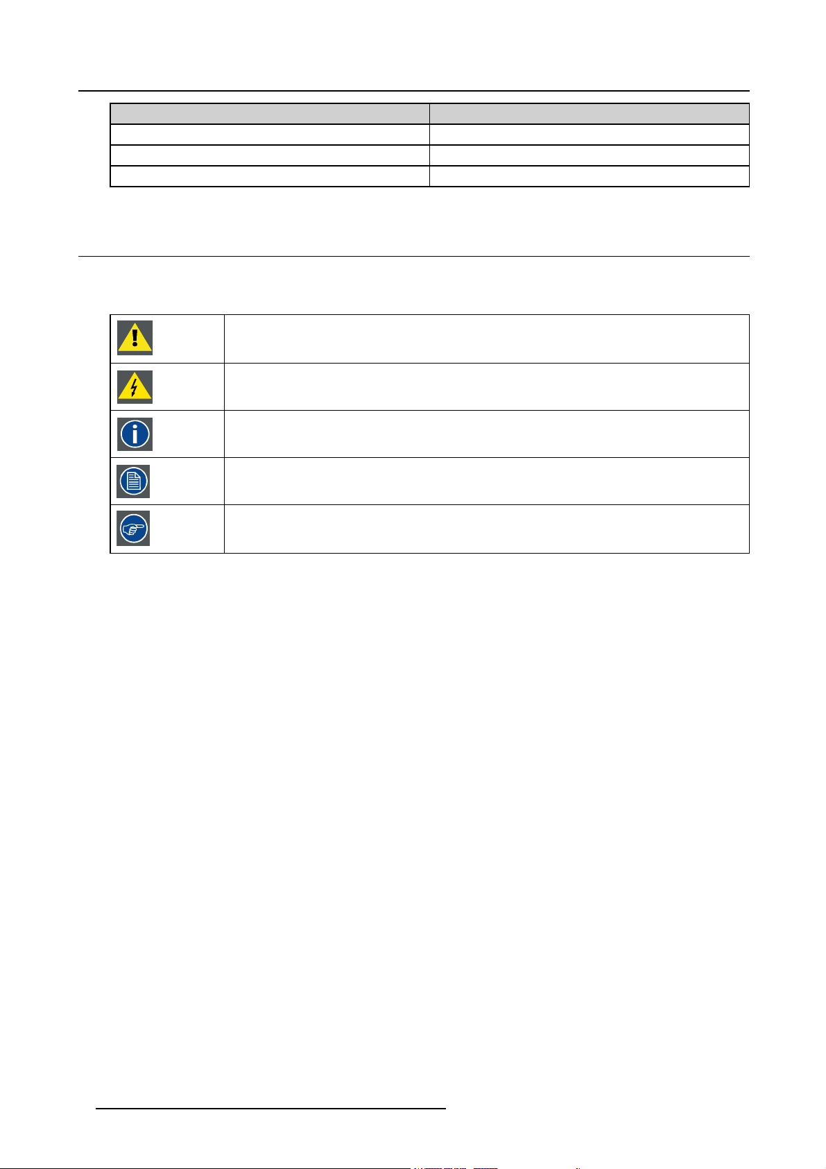
1.4 Symbols and fonts
Symbol overview
The following icons are used in the manual :
Caution
Warning
Info, term definition. General info about the term
Note: gives extra information about the described subject
Tip: gives extra advice about the described subject
Font overview
• Buttons are indicated in bold, e.g. OK.
• Menu items are indicated in italic.
• Step related notes, tips, warnings or cautions are printed in italic.
• Procedure related notes, tips, warnings or cautions are printed in bold between 2 lines preceded by the corresponding icon.
6
R59770509 AUTOALIGNMENT HEAD GEN II 26/11/2013
Page 15
2. SAFETY
Overview
• Safety labels
• Safety and warnings
2.1 Safety labels
Overview of the safety labels
The table below lists all of the safety related labels that are available on the MES ACURAS HEAD (standard and rugged) versions.
Carefully read these labels and act accordingly.
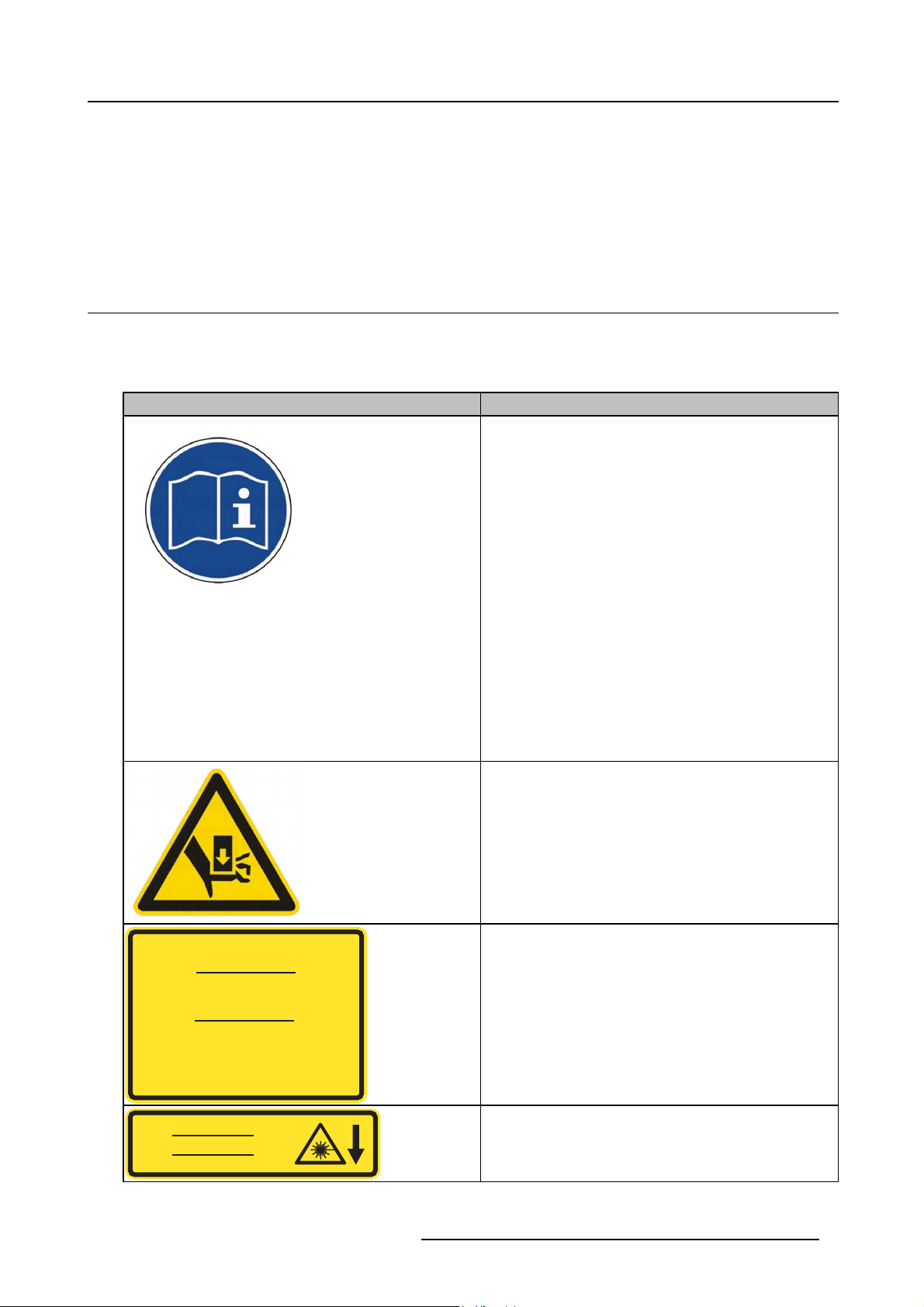
Label Description
Refer to the manual for more detailed information.
2. Safety
LASER RADIATION : DO NOT STARE INTO BEAM
CLASS 2 LASER PRODUCT
RAYONNEMENT LASER
NE PAS REGARDER DANS LE FAISCEAU
APPAREIL À LASER DE CLASSE 2
䉏⏘戟⺓ₜ尐⑬展䟄㽱
Max output / Puissance de sortie max / 㦏⮶戢⒉= 1mW
Wavelength / Longeur d’onde / 㽱栎 = 650 nm
儶䉏⏘ℶ䞮
IEC 60825-1 Ed. 2.0 2007
LASER APERTURE
OUVERTURE LASER
䉏⏘戟⺓ⷣ㈓
Fingers can be clamped between moving parts. (Only available
on standard version).
Class 2 laser radiation: do not stare into the beam.
Position of the laser aperture.
R59770509 AUTOALIGNMENT HEAD GEN II 26/11/2013 7
Page 16
2. Safety
Label Description
WARNING: Hazardous moving parts.
Keep fingers and other body parts away.
ATTENTION: Parties mobiles dangereuses.
Tenir eloignés les doits et autres parties du corps.
巵⛙᧶☀棸扟┷捷ↅᇭ㓚㖖✛愺⇢␅Ⅵ捷⒕庆扫䱊
C
N
Y
M
E
E
E
G
R
D
T
Ê
R
R
A
S
U
’
T
R
G
O
E
N
P
C
E
Moving parts: keep fingers, other body parts, loose clothes,
jewelry, rings etc. away.
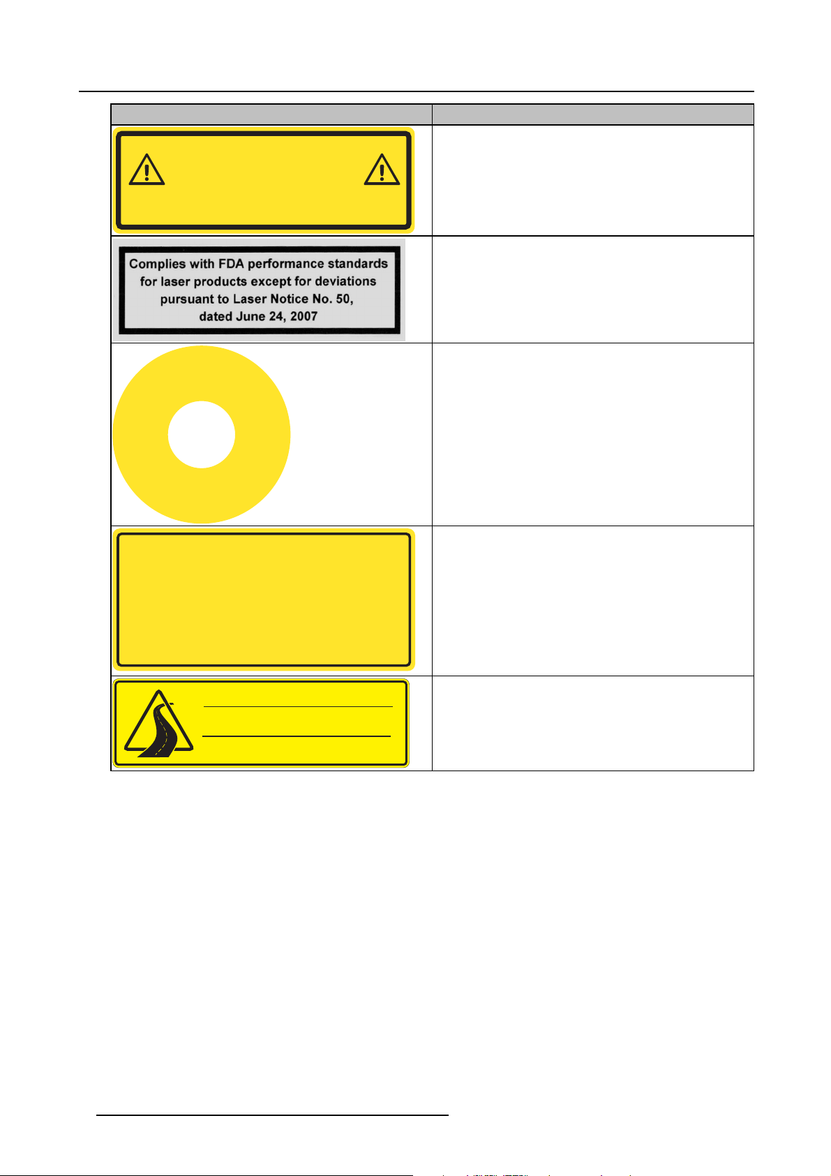
FDA compliancy
Emergency stop: engage in case of a dangerous situation. Do
not reset before the situation is fully safe again.
侶
㊴
! WARNING !
The RJ-45 connector is not an Ethernet connection. Do not connect
to an Ethernet port. Possible risk of damage to the equipment and port!
! ATTENTION !
Le connecteur RJ-45 n’est pas un connecteur Ethernet. Ne pas connecter
sur un port Ethernet. Risque d’endommager le matériel et le port!
巵⛙
5-扭㘴⣷ₜ㢾₹ⅴ⮹几扭㘴ↅᇭₜ尐㘴⏴ⅴ⮹几䵾♲ᇭ
♾厌㦘㗮⧞幍✛䵾♲䤓歝棸ᇭ
㷱
⋫
WARNING : Check manual for shipping instructions
ATTENTION : Consultez le manuel pour
les instructions d’expédition
巵⛙᧶㩴䦚孔扟㖖ⅳ㓚␛
This RJ45 connector is not a network connector. One of the
pins is a power signal.
Check manual for shipping instruction. (Only available on
rugged version).
8 R59770509 AUTOALIGNMENT HEAD GEN II 26/11/2013
Page 17
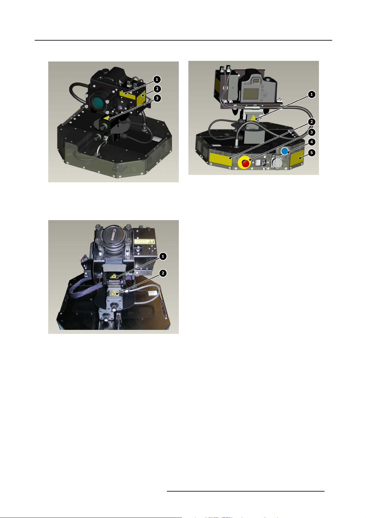
Position of the safety labels (on standard version)
Image 2-2
Image 2-1
Labels: position
1 Laser aperture
2 Laser radiation
3Clampedfingers
Labels: position
1 Clamped fingers
2Movingparts
3 Emergency stop
4 Refer to manual for information
5 RJ45 connector is not an Ethernet connection
2. Safety
Image 2-3
Labels: position
1Clampedfingers
R59770509 AUTOALIGNMENT HEAD GEN II 26/11/2013 9
Page 18
2. Safety
2Clampedfingers
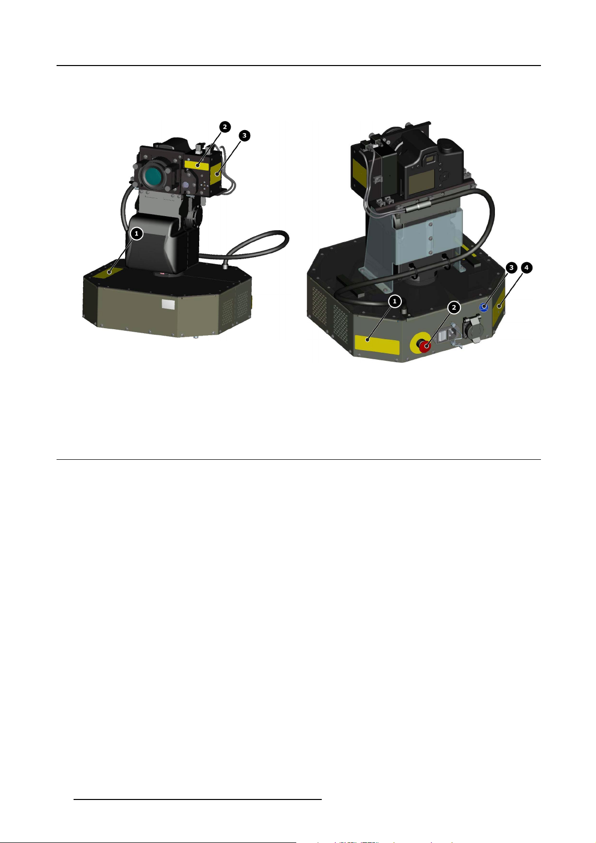
Position of the safety labels (on rugged version)
Image 2-4
Labels: position
1 Check manual for shipping instruction
2 Laser aperture
3 Laser radiation
Image 2-5
Labels: position
1Movingparts
2 Emergency stop
3 Refer to manual for information
4 RJ45 connector is not an Ethernet connection
2.2 Safety and warnings
About this chapter
It is necessary to read this chapter prior to starting any activity on the device. It contains valuable and critical information to ensure
safety of the operator, the service technician or other people in the neighborhood of the device.
Overview
• Notice on safety
• Installation instructions
• Owner’s record
• Warnings
• Plug types
• Prevent personal injury
• Device damage
• Environment condition check
• Repacking
• Emergency stop
•Movingparts
• Class 2 laser
• SFTP Cat.5e cable warning
• Vibrations
2.2.1 Notice on safety
Notice on Safety
This equipment is built in accordance with the requirements of the international safety standards IEC60950-1, EN60950-1,
UL60950-1 and CAN/CSA - C22.2 No.60950-1, which are the safety standards of information technology equipment including
electrical business equipment. These safety standards impose important requirements on the use of safety critical components,
10
R59770509 AUTOALIGNMENT HEAD GEN II 26/11/2013
Page 19
materials and isolation, in order to protect the user or operator against risk of electric shock and energy hazard, and having access
to live parts. Safety standards also impose limits to the internal and external temperature rises, radiation levels, mechanical stability
and strength, enclosure construction and protection against the risk of fire. Simulated single fault condition testing ensures the
safety of the equipment to the user even when the equipment’s normal operation fails.
2.2.2 Installation instructions
Installation Instructions
• Before operating this equipment please read this manual thoroughly, and retain it for future reference.
• Installation and preliminary adjustments can be performed after reading the documentation manuals in detail.
• All warnings on the device and in the documentation manuals should be adhered to.
• All instructions for operating and use of this equipment must be followed precisely.
2.2.3 Owner’s record
Owner’s Record
The part number and serial number can be found on the label at the back side of the device. Record these numbers in the table
below. Refer to them whenever you call your Barco dealer regarding this product.
Part Number:
Serial Number:
Dealer:
2. Safety
2.2.4 Warnings
Safety warnings
• To prevent fire or electrical shock hazard, do not expose this equipment to rain or moisture!
• This product should be operated from an AC power source. Power input is auto-ranging from 100 V to 240 V.
• All equipment in the system is equipped with a 3-wire grounding plug, a plug having a third (grounding) pin. This plug will only
fit into a grounding-type power outlet. This is a safety feature. If you are unable to insert the plug into the outlet, contact your
electrician to replace your obsolete outlet. Do not defeat the purpose of the grounding-type plug.
• Do not allow anything to rest on the power cord. Do not locate this product where persons will walk on the cord. To disconnect
the cord, pull it out by the plug. Never pull the cord itself.
• If an extension cord is used with this product, make sure that the total of the Ampere ratings on the products plugged into the
extension cord does not exceed the extension cord Ampere rating.
• Never push objects of any kind into this product through cabinet slots as they may touch dangerous voltage points or short out
parts that could result in a risk of fire or electrical shock.
• Never spill liquid of any kind on the product. Should any liquid or solid object fall into the cabinet, unplug the set and have it
checked by qualified service personnel before resuming operations.
• Lightning - For added protection for this product during a lightning storm, or when it is left unattended and unused for long
periods of time, unplug it from the wall outlet. This will prevent damage to the device due to lightning and AC power-line surges.
2.2.5 Plug types
WARNING: The AC mains power adapter must be grounded (earthed) via the supplied 3 conductor AC power
cable. If the supplied p ower cable is not the correct one, co nsu lt your dealer.
Plug types
a. Mains lead (AC Po wer cord) with C EE 7 plug u p to 16 A
CEE 7
E
L
N
Image 2-6
The colors of the mains lead are colored
R59770509 AUTOALIGNMENT HEAD GEN II 26/11/2013
in accordance with the following code:
11
Page 20

2. Safety
Green + yellow: Earth (Ground)
Blue: Neutral
Brown: Line (Live)
b. PowercordwithNEMA5/15plugupto15A
NEMA 5/15
E
L
N
Image 2-7
The wires of the power cord are colored in accordance with the following code.
Green or yellow + green: Earth (Ground)
Blue or white: Neutral
Brown or black: Line (Live)
2.2.6 Prevent personal injury
To prevent personal injury
To prevent injuries and physical damage, always read this manual and all labels on the system before connecting to the wall outlet.
To prevent injuries, take note of the weight of the device.
Before attempting to remove any of the device’s covers, you must turn off the device and disconnect from the wall outlet.
2.2.7 Device damage
To prevent device damage
In order to ensure that correct airflow is maintained, and that the device complies with Electro-Magnetic Compatibility requirements,
it should always be operated with all of it’s covers in place.
Ensure that nothing can be spilled on, or dropped inside the device. If this does happen, switch off and unplug the mains supply
immediately. Do not operate the device again until it has been checked by qualified service personnel.
The device must always be mounted in a manner which ensures free flow of air into its air inlets and unimpeded evacuation of the
hot air exhausted from its cooling system. Heat sensitive mat
erials should not be placed in the path of the exhausted air.
2.2.8 Environment condition check
Environment condition check
A device must always be mounted in a manner which ensures the free flow of clean air into the device’s ventilation inlets. For
installations in environments where the device is subject to excessive dust, then it is highly advisable and desirable to have this dust
removed prior to it reaching the device clean air supply. Devices or structures to extract or shield excessive dust well away from the
device are a prerequisite; if this is not a feasible solution then measures to relocate the device to a clean air environment should be
considered.
It is the clients responsibility to ensure at all times that the device is protected from the harmful effects of hostile airborne particles
in the environment of the device. The manufacturer reserves the right to refuse repair if a device has been subject to negligence,
abandon or improper use.
Ambient temperature conditions
Max. ambient temperature : +40°C or 104°F
Min. ambient temperature: 0°C or 32°F
Storage temperature: -20°C to +60°C (–4°F to 140°F)
Humidity Conditions
Storage: 0 to 98% relative humidity, non-condensing
Operation: 0 to 85% relative humidity, non-co
ndensing
Environment
Do not install the device in a site near heat sources such as radiators or air ducts, or in a place subject to direct sunlight, excessive
dust or humidity. Be aware that room heat rises to the ceiling; check that temperature near the installation site is not excessive.
12
R59770509 AUTOALIGNMENT HEAD GEN II 26/11/2013
Page 21
Environment condition check
The device must always be mounted in a manner which ensures the free flow of clean air into the air intake and out of the air outlet.
2.2.9 Repacking
On Repacking
Save the original shipping carton and packing material; they will come in handy if you ever have to ship your e
mum protection, repack your set as it was originally packed at the factory.
2.2.10 Emergency stop
Emergency stop
The emergency stop button is the large, circular red switch located at the rear side of the device. Pressing the emergency stop
button will disconnect the main power going to the modules of the MES ACURAS HEAD (RUGGED). To release it, turn the button
in the direction of the arrow. It should only be re-enabled if the situation is fully safe.
Use the emergency stop button only in emergencies.
C
N
Y
M
E
E
E
G
R
D
T
Ê
R
R
A
S
U
’
T
R
G
O
E
N
P
C
E
quipment. For maxi-
2. Safety
侶
㊴
Image 2-8
Emergency button + label
2.2.11 Moving parts
WARNING: Make sure that nobody and nothing is present within an area of 1 meter around the AutoAlignment
Head during operation.
Moving parts
• Keep your hands and fingers away from all moving parts.
• Do not wear loose clothing or jewelry. Keep long hair, clothing, scarves, rings, bracelets, gloves and such away from moving
parts, since they can be caught in moving parts.
• No people are allowed to come near the unit when it is in operation
• Do not operate the unit when other people can come near to the unit.
• Keep children, outsider, and other untrained persons away from the unit and its moving parts.
• Ensure that there is no loose cabling from the unit that can get caught by the moving parts.
Immediately stop operation if Gimbal Pan/Tilt does not respond to control
• Test Gimbal Pan/Tilt movement when initially operating the unit.
• Ensure Pan movement is going full -180º and +180º.
• Ensure Tilt movement is going full -80º and +30º.
• Ensure all controls function smoothly and do not stick or bind when operated.
• Avoid any type of manual intervention when operating the unit.
⋫
㷱
R59770509 AUTOALIGNMENT HEAD GEN II 26/11/2013
13
Page 22
2. Safety
WARNING: Hazardous moving parts.
Keep fingers and other body parts away.
ATTENTION: Parties mobiles dangereuses.
Tenir eloignés les doits et autres parties du corps.
巵⛙᧶☀棸扟┷捷ↅᇭ㓚㖖✛愺⇢␅Ⅵ捷⒕庆扫䱊
Image 2-9
Moving parts warning label
Image 2-10
Moving parts warning label
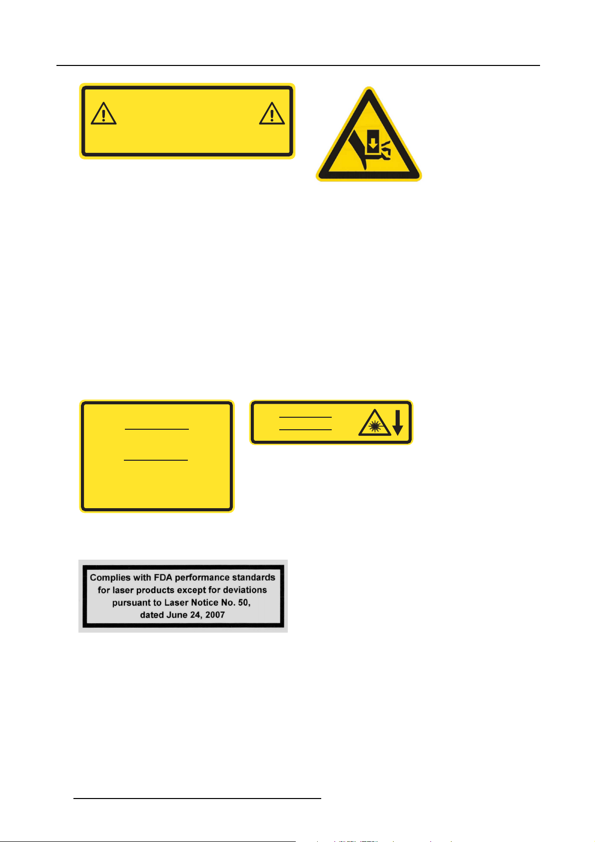
2.2.12 Class 2 laser
Class 2 laser
• The laser device installed on the MES ACURAS HEAD (RUGGED) is classified as a Class 2 laser. Class 2 laser is not considered as an optically dangerous device as the eye reflex will prevent any ocular damage.
• Switch OFF the laser device when not in use.
• Never look into the laser beams directly.
• Avoid direct eye exposure.
• Never operate the unit if other people are in the same room.
• No bystanders are allowed near to or inside the room when the laser device is in operation.
• Never come near to unit during operation.
• Never aim the laser beams to a projector lens. Direct or indirect hitting of a laser beam on to the lens can severely damage to
the optical engines in which case there is a loss of warranty
Following labels can be found on the unit:
LASER RADIATION : DO NOT STARE INTO BEAM
CLASS 2 LASER PRODUCT
RAYONNEMENT LASER
NE PAS REGARDER DANS LE FAISCEAU
APPAREIL À LASER DE CLASSE 2
䉏⏘戟⺓ₜ尐⑬展䟄㽱
Max output / Puissance de sortie max / 㦏⮶戢⒉= 1mW
Wavelength / Longeur d’onde / 㽱栎 = 650 nm
儶䉏⏘ℶ䞮
LASER APERTURE
OUVERTURE LASER
䉏⏘戟⺓ⷣ㈓
Image 2-12
Laser warning label
IEC 60825-1 Ed. 2.0 2007
Image 2-11
Laser warning label
FDA compliancy
Image 2-13
2.2.13 SFTP Cat.5e cable warning
SFTP Cat.5e cable warning
The supplied SFTP Cat.5e cable is a RJ45 cable. It is used for communication between the MES ACURAS HEAD and the MCU via
LEX unit. The total length of the SFTP Cat.5e cable is 50 meter.
Never connect the SFTP Cat.5e cable to an Ethernet card, hub, switch or port or other Ethernet RJ45 connector of an Ethernet
device or MCU. Damage to devices connect
ed to the Ethernet may result.
14
R59770509 AUTOALIGNMENT HEAD GEN II 26/11/2013
Page 23

! WARNING !
The RJ-45 connector is not an Ethernet connection. Do not connect
to an Ethernet port. Possible risk of damage to the equipment and port!
! ATTENTION !
Le connecteur RJ-45 n’est pas un connecteur Ethernet. Ne pas connecter
sur un port Ethernet. Risque d’endommager le matériel et le port!
巵⛙
5-扭㘴⣷ₜ㢾₹ⅴ⮹几扭㘴ↅᇭₜ尐㘴⏴ⅴ⮹几䵾♲ᇭ
♾厌㦘㗮⧞幍✛䵾♲䤓歝棸ᇭ
Image 2-14
SFTP Cat.5e cable warning label
2.2.14 Vibrations
Vibrations
The standard version of the AutoAlignment Head, being MES ACURAS HEAD (R9843500) is not motion base compatible. It is only
to be installed on still or non-moving structures.
The rugged version of the AutoAlignment Head, being MES ACURAS HEAD RUGGED (R9843501) is motion base compatible,
which means it can be installed on motion based simulators or on moving structures
2. Safety
R59770509 AUTOALIGNMENT HEAD GEN II 26/11/2013 15
Page 24

2. Safety
16 R59770509 AUTOALIGNMENT HEAD GEN II 26/11/2013
Page 25
3. Compliancy
3. COMPLIANCY
Introduction
To meet EMC compliancy, it is required to take some precaution. See topic below.
Overview
• EMC shielding clamps
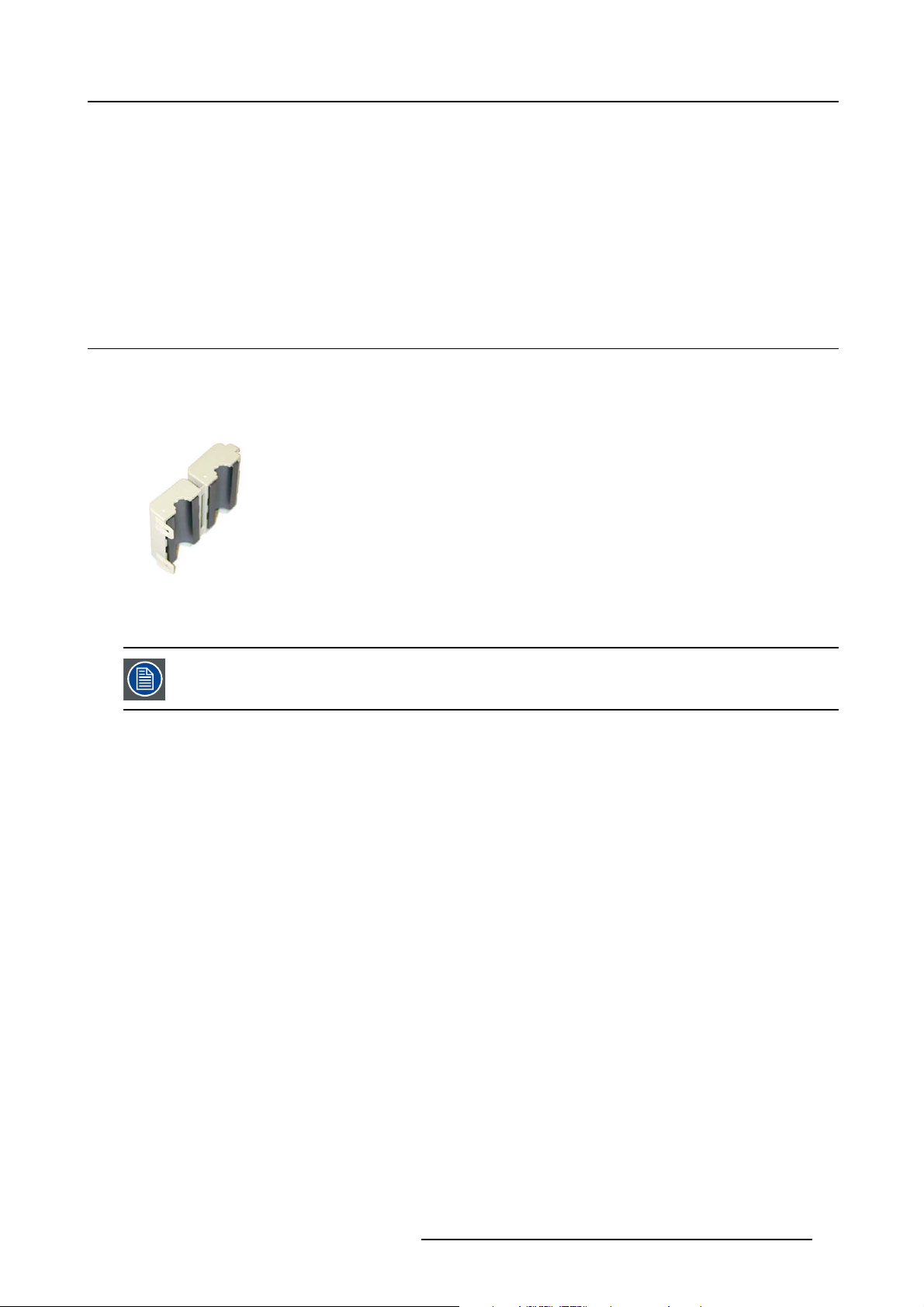
3.1 EMC shielding clamps
EMC shielding clamps
When replacing some of the cables, always put back the EMC shielding clamps (Ferrites) in their original position if they were present
before.
Image 3-1
EMC shielding clamp
Depending on the type of EMC shielding clamp, use a pair of cutting pliers and/or a slotted screwdriver to open the clamp.
Some cables must make a loop through the EC shielding clamps!
R59770509 AUTOALIGNMENT HEAD GEN II 26/11/2013 17
Page 26

3. Compliancy
18 R59770509 AUTOALIGNMENT HEAD GEN II 26/11/2013
Page 27
4. PACKAGING
Overview
• Content
• Unpacking
• Shipping bracket
4.1 Content
Content
Description Article number
AutoAlignment Head (standard/rugged) R765840/R7658402
Power cord (connectors C13 and CEE7)
Power cord (connectors C13 and NEMA
5–15)
Power cord (connector C13 and PCR-3)
S/FTP CAT5e control cable (connectors
RJ45)
USB extender or LEX unit (Icron LEX)
Ferrite split core B195382 2
Adhesive label: WARNING No Ethernet
connection
AutoAlignment Head Quick install guide R59770598 1
AutoAlignment Head Service manual R59770510 1
AutoAlignment Head User and installation
manual
CD-ROM (Calibration files for
Spectrometer)
R326103 1
V326111 1
Z3487503 1
CBL-3380–61 1 (length 50m)
-
R870792 2
R59770509 1
-
4. Packaging
Quantity
1
1
1
4.2 Unpacking
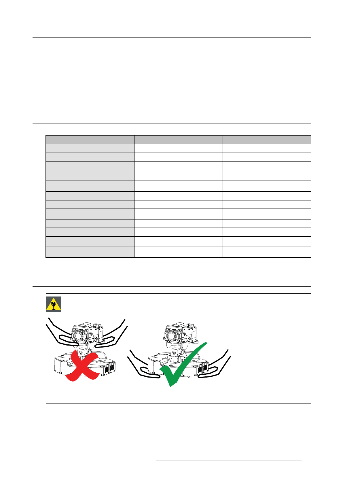
CAUTION: Hold the unit at the bottom box to lift and move it. Never hold the camera or Gimbal to lift theAu-
toAlignment Head.
Image 4-1
Lifting instructions: Barco (standard and rugged) version
Packaging
Cardboard boxes and foam are used to protect the device during shipping.
R59770509 AUTOALIGNMENT HEAD GEN II 26/11/2013
19
Page 28
4. Packaging
Save the original packag ing for future shipment. For maximum protection while shipping the unit, always
pack it as it was packed during first delivery.
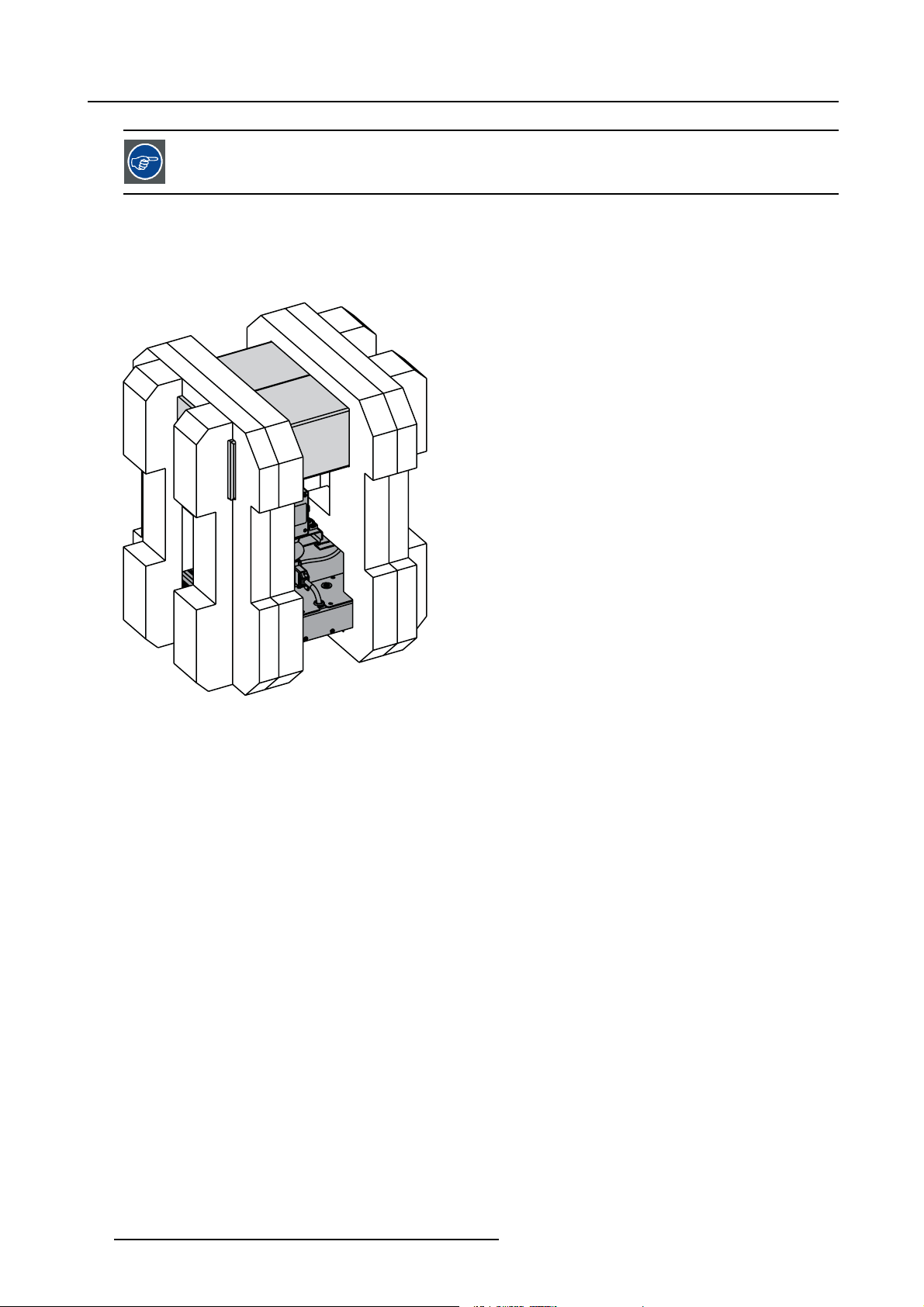
How to unpack the AutoAlignment Head?
1. Carefully cut the tape on the top lid of the box.
Warning: Follow the relevant safety precautions while using a knife.
2. Open the main box and carefully lift out the foam parts, carboard box and AutoAlignment Head as one unit
Image 4-2
Packaging: content of the m ain box
3. Remove the left and right foam part to release the AutoAlignment Head and a second cardboard box.
20
R59770509 AUTOALIGNMENT HEAD GEN II 26/11/2013
Page 29
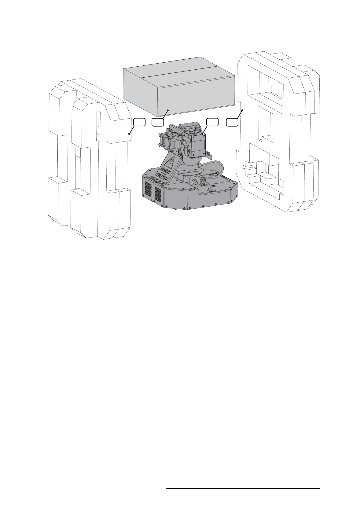
A B C D
4. Packaging
Image 4-3
Packaging: remove the foam parts (AutoAlignment Head standard version)
A Foam protection part
B Second cardboard box
C AutoAlignment Head
R59770509 AUTOALIGNMENT HEAD GEN II 26/11/2013 21
Page 30
4. Packaging
D Foam protection part
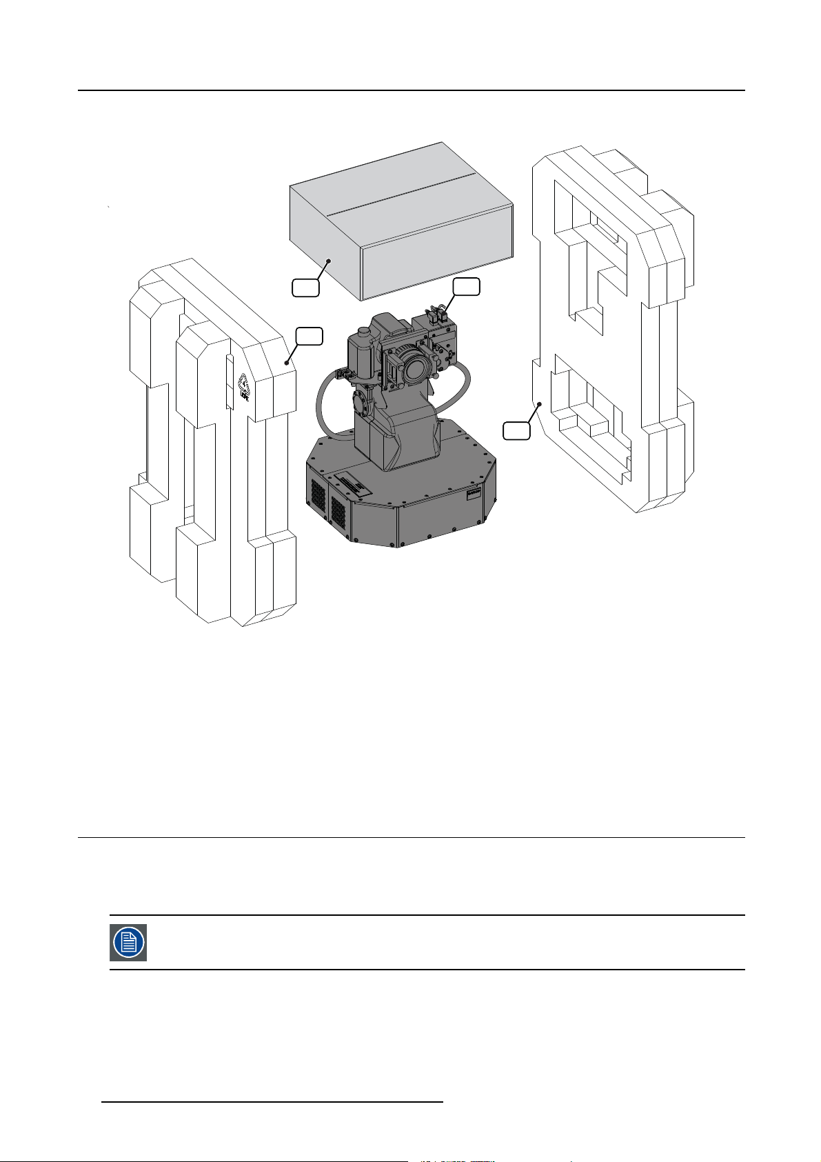
B
A
Image 4-4
Packaging: remove the foam parts (AutoAlignment Head rugged version)
A Foam protection part
B Second cardboard box
C AutoAlignment Head
D Foam protection part
4. Carefully cut the tape on the top lid of the second cardboard box
Warning: Follow the relevant safety precautions while using a knife.
5. Remove the parts from this box.
6. Check if all parts are available. See "Content", page 19.
C
D
4.3 Shipping bracket
Introduction
When the AutoAlignment Head is shipped, the shipping bracket must be fixed to it. This bracket prevents the Gimbal unit from
being damaged due to handling actions during shipment. The shipping bracket must be removed prior to installing the unit.
If this AutoAlignment Head must be shipped ever again, it is necessary to first install the shipping bracket.
Overview
• Removing the shipping bracket
• Installing the shipping bracket
22
R59770509 AUTOALIGNMENT HEAD GEN II 26/11/2013
Page 31

4.3.1 Removing the shipping bracket
Necessary tools
Torx screwdriver T10
How to remove the shipping bracket?
1. Remove all screws fixing the shipping bracket to the AutoAlignment Head.
4. Packaging
Image 4-5
Shipping bracket removal: standard version
Image 4-6
Shipping bracket removal: rugged version
2. Remove the shipping bracket.
3. Insert all screws in the AutoAlignment Head again and tighten them.
4.3.2 Installing the shipping bracket
CAUTION: The shipping bracket must always be installed on the AutoAlignment Head prior to shipping it!
Necessary tools
Torx screwdriver T10
How to install the shipping bracket?
1. Adjust pan and tilt to align the holes on the AutoAlignment Head exactly to the holes on the shipping bracket. This corresponds
to pan 90° / tilt 0° for the standard version and pan 0° / tilt 0° for the rugged version.
R59770509 AUTOALIGNMENT HEAD GEN II 26/11/2013
23
Page 32

4. Packaging
Image 4-7
Orientation to fix shipping bracket: standard version
Tip: On the standard version, this positioning can be done manually (Pan knob and Tilt knob) or through the XDS RACU us er
interface.
2. Power off the system and remove the power cord.
3. Disconnect the AutoAlignment Head.
4. Remove the AutoAlignment Head from its support.
5. Fix the shipping bracket to the unit.
Image 4-8
Orientation to fix shipping bracket: rugged version
Image 4-9
Shipping bracket: standard version
Tip: To install the shipping bracket, follow the removal procedure in reverse order.
24
Image 4-10
Shipping bracket: rugged version
R59770509 AUTOALIGNMENT HEAD GEN II 26/11/2013
Page 33

5. Facility and system requirements
5. FACILITY AND SYSTEM REQUIREMENTS
About this chapter
This chapter provides information about the installation requirements such as temperature, humidity, dimensions, power net, safety
area around the device. Also the air intake and air outlet area of the device are considered.
Overview
• Environmental requirements
• Dimensions
•Airflow requirements
• Power requirements
• View requirements
• Access requirements
• Luminance requirements
5.1 Environmental requirements
Ambient temperature conditions
Storage:
• -20°C to +60°C (-4°F to 140°F)
Operation:
• Max. ambient temperature : +40°C or 104°F
• Min. ambient temperature : 0°C or 32°F
Humidity Conditions
Storage: 0 to 98% relative humidity, non-condensing
Operation: 0 to 85% relative humidity, non-condensing
Environment
Do not install the device in a site near heat sources such as radiators or air ducts, or in a place subject to direct sunlight, excessive
dust or humidity. Be aware that room heat rises to the ceiling; check that temperature near the device is not excessive.
Environment condition check
The device must always be mounted in a manner which ensures the free flow of clean air into the air intake and out of the air outlet.
Environmental light conditions
During operation of the AutoAlignment Head , the environment should be fully dark to guarantee correct measurements. Even the
light of a small standby LED which is visible on the screen may le
Next to that, there should be no light (not even stray light) pointing to the ocular while the diaphragm of the camera is open. A light
beam entering the ocular while the camera’s diaphragm is open may lead to damage to the camera.
ad to bad measurement results.
5.2 Dimensions
Dimensions
The total weight of the AutoAlignment Head standard version is 8.26 kg. The weight of the AutoAlignment Head Rugged version is
11. 5 k g.
Dimensions of both versions can be found in the drawings below.
R59770509 AUTOALIGNMENT HEAD GEN II 26/11/2013
25
Page 34

5. Facility and system requirements
Image 5-1
Dimension: AutoAlignment Head (standard version)
1 M6 Mounting stud
26 R59770509 AUTOALIGNMENT HEAD GEN II 26/11/2013
Page 35

2 Location pin Ø 6mm
5. Facility and system requirements
304,4
[11,984]
152,2
[5,992]
82,6
82,6
[3,252]
[3,252]
325,86
325,86
[12,829]
[12,829]
162,2
[6,386]
108
[4,252]
324,4
[12,772]
108
[4,252]
82,6
[3,252]
66,3 x45° (4x)
[2,610]
(3x)
14
[,551]
[8,931]
[8,931]
226,84
226,84
(=Gimbal Tilt Axis)
397,57
[15,652]
152,2
152,2
[5,992]
[5,992]
Image 5-2
Dimension: AutoAlignment Head (rugged version)
1 M6 Mounting stud
2 Location pin Ø 6mm
(=Gimbal Pan Axis)
13
[,512]
5.3 Air flow requirements
Air flow requirements
It is important to keep the air grids unblocked. A free area of at least 30 cm should be available around the air grids.
178,2
178,2
[7,016]
[7,016]
R59770509 AUTOALIGNMENT HEAD GEN II 26/11/2013
27
Page 36

5. Facility and system requirements
Image 5-3
AutoAlignment Head : position of air grids
5.4 Power requirements
Mains power
Mains power must be in the range 100–250V, 50–60Hz.
Power consumption
The total power consumption of the AutoAlignment Head is 25 Watt at 230 Volt.
5.5 View requirements
Design Eye Point
The Design Eye Point is the position from which the user is intended to view the total image for an optimal view of it.
Camera position
The best position for the AutoAlignment Head is that position where its camera is in the Design Eye Point.
Camera/Spectrometer field of view
Adequate space must be provided around the AutoAlignment Head. No physical or mechanical obstruction should be present in the
camera or spectrometer field of view.
5.6 Access requirements
AutoAlignment Head location and access
There must be enough space around the AutoAlignment Head to allow access to and flawless operation of the unit.
Following rules must be taken into account:
28
R59770509 AUTOALIGNMENT HEAD GEN II 26/11/2013
Page 37

5. Facility and system requirements
• a minimum safety distance of 1 meter must be considered when the AutoAlignment Head is in operation i.e. no operator and/or
bystanders are allowed within the minimum safety distance during operation.
• never try to stop the moving parts manually, it may damage the motor of the AutoAlignment Head.
• do not wear loose clothing or jewelry. Keep long hair, clothing, scarves, rings, bracelets, gloves and such away from moving
parts, since they can be caught in moving parts.
• never cover the AutoAlignment Head (e.g. with a tissue) when it is powered on or just after it was powered off.
• no mechanical obstruction for the full AutoAlignment Head movement range.
5.7 Luminance requirements
Ambient light
Followings rules must be taken into account:
• stray light and reflections of it should be avoided, e.g. by using dark wall, ceiling and floor color.
• switch off all external light sources during measurements.
• only aimed spotlight should be used to illuminate small areas if required. Make sure that this aimed spotlight d
the screen during measurements.
oes not fall on
R59770509 AUTOALIGNMENT HEAD GEN II 26/11/2013
29
Page 38

5. Facility and system requirements
30 R59770509 AUTOALIGNMENT HEAD GEN II 26/11/2013
Page 39

6. SPECIFICATIONS
Overview
• Hardware layout
• Gimbal range
• Camera FOV
6.1 Hardware layout
Hardware layout: front view
6. Specifications
BA C
K
J
I
H
Image 6-1
AutoAlignment Head (standard version) : parts overview
Label in the image
A
B
C
K
I
D
E
F
G
Image 6-2
AutoAlignment Head (rugged version) : parts overview
Description (standard version) Description (rugged version)
Camera Camera
Spectrometer Spectrometer
Laser pointer Laser pointer
A
C
B
D
E
D Laser aperture Laser aperture
E
F
Optical filter Optical filter
Gimbal cable
PAN–TILT unit cable
G Gimbal Gimbal (PAN–TILT unit)
H
I
J
K
Manual pan knob (See note)
Camera cable Camera cable
Manual tilt knob (See note)
Thumb screws to fix the focus ring Thumb screws to fixthefocusring
not available
not available
F
G
Manual pan and tilt adjustment by using the knobs is only allowed when the AutoAlignment Head is not electrically powered. W hen the device is powered up, the manual pan and tilt knobs are blocked electronically.
Forcing a pan or tilt movement via the knobs might damage the device.
R59770509 AUTOALIGNMENT HEAD GEN II 26/11/2013 31
Page 40

6. Specifications
Hardware layout: top view
A
G
F
Image 6-3
AutoAlignment Head (standard version) : parts overview
Label in the image
A
B
C
B
D
G
F
E
Image 6-4
AutoAlignment Head (rugged version) : parts overview
A
D
B
Description (standard version) Description (rugged version)
Camera: Power On / Off Camera: Power On / Off
Camera: Rotary dial Camera: Rotary dial
C Base frame Base frames
D
Camera lens: Manual / Auto focus Camera lens: Manual / Auto focus
E Air grid Air grid
F
Camera: focus ring Camera: focus ring
G Camera: zoom ring Camera: zoom ring
C
E
Hardware layout: rear bottom view
A
B
I
H
G
F
Image 6-5
AutoAlignment Head (standard version) : parts overview
E
C
D
I
H
H
F
Image 6-6
AutoAlignment Head (rugged version) : parts overview
A
B
C
D
E
Label in the image
A
B
Description (standard version) Description (rugged version)
Camera: Ocular Camera: Ocular
Camera: LCD display Camera: LCD display
32 R59770509 AUTOALIGNMENT HEAD GEN II 26/11/2013
Page 41

6. Specifications
Label in the image
C
D Air grid Air grid
E
F Emergency stop Emergency stop
G
H Mains power connector Mains power connector
I
Description (standard version) Description (rugged version)
Location pin Ø 6mm Location pin Ø 6mm
M6 Mounting studs (and washers + nuts) M6 Mounting studs (and washers + nuts)
Mains power switch Mains power switch
SFTP CAT5e connector (covered by a lid) SFTP CAT5e connector (covered by a lid)
6.2 Gimbal range
Gimbal range
The Gimbal has two degrees of freedom (DOF): pan and tilt. Pan is the left/right rotation if th
position. Tilt is the up / down tilting if in table position.
. The limits are indicated below:
• PAN: range is between -180° and +180° for both AutoAlignment Head versions;
e AutoAlignment Head is in table
Image 6-7
AutoAlignment Head (standard version) : Pan range
-180°+180°
Image 6-8
AutoAlignment Head (rugged version) : Pan range
-180°+180°
R59770509 AUTOALIGNMENT HEAD GEN II 26/11/2013 33
Page 42

6. Specifications
• TILT range is between +30° and -80° for standard version and +30° and -90° for rugged version.
+30°
-80°
Image 6-9
AutoAlignment Head (standard version) : Tilt range
-90°
Image 6-10
AutoAlignment Head (rugged version) : Tilt range
+30°
6.3 Camera FOV
Camera FOV (Field Of View)
The Horizontal and the Vertical Field of View of the camera are
• Camera HFOV: 64°
• Camera VFOV: 45°
These Camera FOV’s correspond to an 18 m m zoom setting on the lens.
34 R59770509 AUTOALIGNMENT HEAD GEN II 26/11/2013
Page 43

7. Installation
7. INSTALLATION
About this chapter
This chapter describes the full installation flow which is a one time operation only: mechanical installation, connectivity, upload of
the correct calibration files for the spectrometer and settings on the Camera.
The AutoAlignment Head can be fixed using the M6 mounting studs, washers and nuts at its bottom. It can be used in table mount
or ceiling mount mode.
CAUTION: The AutoAlignment Head standard version has not been designed to be used on a motion base
platform.
Overview
• Mechanical installation
• Hardware connections
• Driver installation
• Uploading the calibration files
• Importing the license file
• Camera settings
• AutoAlignment parameters
7.1 Mechanical installation
CAUTION: Hold the unit at the bottom box to lift and move it. Never hold the camera or Gimbal t o lift the
AutoAlignment Head.
Image 7-1
Lifting instructions: AutoAlignment Head (standard and rugged) version
CAUTION: Disconnect the mains power supply during the AutoAlignment Head installation. Doing not so
may cause electric shock.
The mechanical support must be solid enough t
is in a good and safe location and position. It should have a positioning hole and three fixation h oles. See
"Dimensions", page 25.
o sustain the weight of the AutoAlignment Head and that it
WARNING: The AutoAlignment Head mu st be instantly and correctly fixated to its mechanical support during
installation.
R59770509 AUTOALIGNMENT HEAD GEN II 26/11/2013 35
Page 44

7. Installation
WARNING: M ake sure that the AutoAlignment Head is instantly secured when it is mounted in ceiling mode
(i.e. hanging upside down). Improper fixation may cause personal injury or device damage.
Necessary tools
Open ended nut spanner 10 mm
How to mount the AutoAlignment Head on a mechanical support?
1. Disconnect the power cable and the SFTP Cat.5e cable from the AutoAlignment Head.
2. Loosen and remove the M6 mounting nuts (3x) and washers (3x) from the M6 mounting studs on the AutoAlignment Head.
A
Image 7-2
A M6 nuts and washers (3x)
3. Align the location pin of the AutoAlignment Head to the positioning hole on the mechanical support and slide it in.
A
B
Image 7-3
A A utoAlignme nt Head
B Mounting plate
4. Orient the AutoAlignment Head until its M6 mounting studs are aligned with their respective fixation holes in the support.
36
R59770509 AUTOALIGNMENT HEAD GEN II 26/11/2013
Page 45

A
B
Image 7-4
A A utoAlignme nt Head
B Mechanical support
5. Insert the mounting studs in their respective holes
6. Install the washers (3x) and screw on the M6 nuts (3x) to fix the Barco to the mechanical support.
7. Installation
A
B
Image 7-5
A A utoAlignme nt Head
B Mechanical support
7. Connect all the power cable and the SFTP Cat.5e cable to the AutoAlignment Head.
7.2 Hardware connections
Overview
• Preparing SFTP Cat.5e cable
• Power connections
• Connecting the LEX unit to the MCU
• Connecting the SFTP Cat.5e cable
• Connection diagram
CAUTION: Disconnect the mains po
may cause electric shock.
7.2.1 Preparing SFTP Cat.5e cable
Necessary parts
• Ferrites: B195382 (2x)
• Warning label: R870792 (2x)
wer supply during the AutoAlignment Head installation. Doing not so
How to prepare SFTP Cat.5e cable?
1. Make a loop at one end of the cable.
R59770509 AUTOALIGNMENT HEAD GEN II 26/11/2013
37
Page 46

7. Installation
Image 7-6
preparation: making a loop
2. Fix this loop using ferrite as indicated in the picture below.
Image 7-7
preparation: fixing the loop
3. Repeat steps 2 and 3 at the other end of this cable.
Image 7-8
preparation: fi xing the loop at the other end of the cable
4. Put one end of the cable in. the middle of warning label as indicated in the picture below.
Note: This warn ing label is an adhesive PVC film.
Image 7-9
preparation: placing the cable on the warning label
5. Fold this warning label so that the cable is stuck in between this label.
Image 7-10
preparation: fi xing th e warnin g label
6. Repeat steps 4 and 5 at the other end of this cable.
Image 7-11
preparation: fixing the warning label at the other end of the cable
7.2.2 Power connections
How to connect the power to the MCU?
1. Connect the supplied power cable to connect the MCU to the power outlet.
2. Plug the female power connector into the male connector at the rear of the MCU.
TOP
Image 7-12
Connectors: mains power (MCU)
How to connect the power to the AutoAlignment Head?
1. Connect the supplied power cable to connect the AutoAlignment Head to the power outlet.
2. Plug the female power connector into the male connector at the rear of the AutoAlignment Head.
38
R59770509 AUTOALIGNMENT HEAD GEN II 26/11/2013
Page 47

TOP
A
Image 7-13
Connectors: mains power (AutoAlignment Head)
3. Secure the connection with the locking buckle. See label A
CAUTION: Only use the original power cables.
CAUTION: Never use a power cable that is damaged. Replace it by a new original one.
7. Installation
7.2.3 Connecting the LEX unit to the MCU
How to connect the LEX unit to the MCU?
1. Place the LEX unit close to the MCU.
2. Connect the LEX unit USB cable (male plug ) directly to one of the USB ports (female connector) on the MCU. See image 7-14.
Note: Do not connect the LEX unit to the M CU via a US B hub.
A
B
Image 7-14
AMCU
B LEX unit
7.2.4 Connecting the SFTP Cat.5e cable
Make sure that both ends of the SFTP Cat.5e cable are looped and that the warning labels are attached at both
ends.
How to connect the SFTP Cat.5e cable?
1. Connect one end of the supplied SFTP Cat.5e cable to the LEX unit.
R59770509 AUTOALIGNMENT HEAD GEN II 26/11/2013
39
Page 48

7. Installation
B
D
C
A
Image 7-15
Connecting SFTP Cat.5e cable to LEX unit
A SFTP Cat.5e cable
B A utoAlignme nt Head
CLEXUnit
D RJ 45 connector lid close
2. Open the lid and connect the other end of the supplied SFTP Cat.5e cable to the AutoAlignment Head.
B
D
A
Image 7-16
Connecting SFTP Cat.5e cable to LEX unit
A SFTP Cat.5e cable
B A utoAlignme nt Head
CLEXUnit
D RJ 45 connector lid open
7.2.5 Connection diagram
Diagram
F
TOP
C
TOP
B
E
C
D
A
Image 7-17
Connection diagram
A SFTP Cat 5e cable
B A utoAlignme n
CLEXUnit
DMCU
E Power to the XDS RACU MCU from the mains power supply (wall outlet)
FPowertot
t Head
he AutoAlignment Head from the mains power supply (wall outlet)
40 R59770509 AUTOALIGNMENT HEAD GEN II 26/11/2013
Page 49

7. Installation
7.3 Driver installation
Driver installation
By default the drivers for the AutoAlignment Head (laser, spectrometer and camera) are installed on the MCU by the time of delivery.
No additional action is required.
Only in case of hard disk replacement in the MCU, it is required to run one executable to install all drivers again.
Article number File na me
MCUAutoAlignHardwareDrivers.exe
Download from
TDE on Barco’s IntranetR33224600
Barco’s secured website:
ttps://my.barco.com
h
7.4 Uploading the calibration files
Overview
• Uploading the spectrometer calibration file
• Uploading the camera calibration file
7.4.1 Uploading the spectrometer calibration file
Overview
A set of calibration data is required to guarantee accurate measurements of the spectrometer. This calibration data is available in
the calibration file (<filename>.cal) on the CD-ROM (created by Ocean Optics) which is delivered with the AutoAlignment Head. The
CD ROM label typically includes the serial number of the spectrometer, e.g. USB4F03653.
The calibration file must be uploaded to the MCU, prior to connecting the spectrometer to the MCU.
It is possible to connect more than one spectrometer to a single MCU; In this case the user needs to manually create a folder
on the MCU for each spectrometer. The name of each folder must be the serial number of the corresponding spectrometer. E.g.
C:\Program Files\Barco\XDS\Resources\Spectrometer\USB4F03653.
It is advised to store the calibration fi les of all owned spectrometers on all owned MCU’s: in that situation,
you can freely use each AutoAlignment Head in any display system.
How to upload the spectrometer calibration file?
1. Run the Barco delivered CD on the MCU.
2. Copy the correct spectrometer calibration file called <filename>.cal.
3. Save the spectrometer calibration file to the correct location on the MCU, without changing its name:
C:\Program Files\Barco\XDS\Resources\Spectrometer\<serial number>, where <serial number> is the serial number of the
corresponding spectrometer
Tip: If this folder does not exist y et, it must be manually created.
Getting the serial number of the spectrometer
If the spectrometer has already been connected to the XDS RACU, stop and restart the XDS RACU software on the MCU. Once the
XDS RACU server is running again, the serial number of the spectrometer can be read from the XDS RACU Server Console:
R59770509 AUTOALIGNMENT HEAD GEN II 26/11/2013
41
Page 50

7. Installation
Image 7-18
XDS RACU Server Console
The serial number of the spectrometer can also be read from the label on it:
Image 7-19
Spectrometer: serial number
7.4.2 Uploading the camera calibration file
Overview
By default, the camera is fully calibrated and no further action is required to guarantee correct measurements. For future applications,
it might be required to upload a new calibration file to the MCU. At that time, the calibration file will be provided by Barco.
How to upload the camera calibration file?
1. Save the camera calibration file to the following location on the MCU, without changing its name
- C:\Program Files\Barco\XDS\Resources\Camera\<serial number>.
Getting the serial number of the camera
If the camera has already been connected t
RACU server is running again, the serial number of the camera can be read from the XDS RACU Server Console:
o the XDS RACU, stop and restart the XDS RACU software on the MCU. Once the XDS
Image 7-20
XDS RACU Server Console
42 R59770509 AUTOALIGNMENT HEAD GEN II 26/11/2013
Page 51

7. Installation
7.5 Importing the license file
The license file is linked to – amongst other things – the hostname of the computer on which the according
software is running. As a result, a new license file is required when the hostname of this computer is changed.
Overview
A license file is required to run the XDS RACU software. The user has to send a request to Barco for the license fi le explicitly
mentioning the feature(s) required: Acuras, OmniBlend and/or AutoGeometry.
How to import the license file?
1. See the XDS RACU user guide R597705 08 for more information.
7.6 Camera settings
Overview
• Fixed camera settings
• Lens cap
• Zoom
• Focus
7.6.1 Fixed camera settings
Camera settings
To guarantee proper working, the camera settings should never be changed! The default settings of the various selection switches
are listed below:
• Power switch: ON
• Rotary dial position: M
• Focus selection switch on the camera lens: MF
R59770509 AUTOALIGNMENT HEAD GEN II 26/11/2013
43
Page 52

7. Installation
Image 7-21
Camera settings
7.6.2 Lens cap
Lens cap setting
Remove the lens cap before turning on the camera. If you turn on the camera before removing the lens cap, no image will be visible
when looking through its ocular.
7.6.3 Zoom
Zoom setting
By default, zoom has been set to 18 mm (Wide view) in the factory and doesn’t need to be changed. If you decide that zoom setting
should be changed in a specific application, adjust it prior to setting focus.
Necessary tools
Torx screwdriver T20
How to adjust the zoom setting?
1. Loosen the four screws fixing the zoom ring brackets half a turn anticlockwise. See label 1
44
R59770509 AUTOALIGNMENT HEAD GEN II 26/11/2013
Page 53

7. Installation
1 1
1 1
Image 7-22
Zoom: loosening the four screws
2. Turn the zoom ring to set to the desired zoom.
3. Push the zoom ring brackets against the lens (see label 1) and tighten four screws to fix the zoom ring brackets (see label 2).
22
1
1
22
Image 7-23
Zoom: tightening the four screws
7.6.4 Focus
Prior to adjusting focus, make sure the camera lens is set to MF (Man ua l Focus). See image 7-21.
How to adjust the focus s etting?
1. Loosen the four screws fixing the focus ring brackets half a turn anticlockwise. See label 1
R59770509 AUTOALIGNMENT HEAD GEN II 26/11/2013
45
Page 54

7. Installation
1 1
1 1
Image 7-24
Focus: loosening 4 thumbscrews
2. Turn the focus ring to set to the required focus.
Note: If the distance between camera and different points on the screen varies, then set the focus to the average distance to
the screen.
3. Push the focus ring brackets against the lens (see label 1) and tighten the thumbscrews to fix the focus ring brackets (see label
2).
22
11
22
Image 7-25
Focus: tightening 4 thumbscrews
7.7 AutoAlignment parameters
Overview
The AutoAlignment parameters on the Options page of the XDS RACU user interface are informatory only. The password protected
AutoAlignment parameters may only be changed by authorized Barco personal.
46
R59770509 AUTOALIGNMENT HEAD GEN II 26/11/2013
Page 55

7. Installation
Image 7-26
AutoAlignment settings: Acuras parameters
Image 7-27
AutoAlignment settings: AutoGeometry parameters
R59770509 AUTOALIGNMENT HEAD GEN II 26/11/2013 47
Page 56

7. Installation
Image 7-28
AutoAlignment settings: OmniBlend parameters
Image 7-29
AutoAlignment settings: Warp AutoGeometry parameters
CAUTION: Make sure that you have selected the correct display system type “Rear Projected Do me or Cross
Cockpit Collimated Display” from the System Type drop down box, prior to changing and saving the corre-
sponding system type Omniblend parameters.
CAUTION: Make sure t hat you have selected the correct display system type “Rear Projected Dome or Col-
limator with Slide Projector” from the System Type drop down box, prior to changing and saving the corresponding system type Wa
48 R59770509 AUTOALIGNMENT HEAD GEN II 26/11/2013
rpAutoGeometry parameters.
Page 57

8. Getting started
8. GETTING STARTED
About this chapter
In this chapter, we describe the procedures that are required to come to an AutoAlignment Head that is ready to be operated. It is
assumed that the XDS RACU MCU and eRACU are fully connected, installed and configured and that the AutoAlignment Head is
fully installed as well (see previous chapter).
After having powered the full system and having selected the correct Display system from the User Interface, plugins for the Camera,
Spectrometer and Gimbal must be enabled in the XDS RACU software and the Gimbal home position can be changed.
In applications where it is required to have multiple physical positions where the AutoAlignment Head can be installed, these positions must be defi ned. This can be the case if a mechanical module (e.g. cockpit, metal beams) is in
View of the AutoAlignment Head.
In a next step, the operator must define the locations on the projected image where the Spectrometer and Camera should be pointed
at during measurements, and learn those positions to the AutoAlignment Head. For Dynacolor measurements and gray level correction, 1 single point is used, for uniformity corrections multiple points need to be defined.
Finally the ECR (Enhanced Contrast Ratio, or adjustable iris in the projection lens) can be calibrated if available. Now the AutoAlignment Head is fully ready to be operated.
Overview
• Starting up the MCU, eRACU and AutoAlignment Head
• Connecting to a display
•Configuring the software
•Defining multiple head location
• Setting Gimbal Home Position
•Defining positions
•ECRcalibration
part obstructing the Field of
8.1 Starting up the MCU, eRACU and AutoAlignment Head
Overview
Follow the startup sequence mentioned below.
•MCU
• eRACU
• AutoAlignment Head
It is assumed that all hardware connection related to MCU, eRACU and AutoAlignment Head have been completed.
8.1.1 StartinguptheMCU
How to start up the MCU?
Switch on the power switch.
Image 8-1
Starting up the MCU
It is not required to log in on Windows on the MCU in order for the eRACU to connect to the XDS RACU server.
R59770509 AUTOALIGNMENT HEAD GEN II 26/11/2013 49
Page 58

8. Getting started
CAUTION: In order to use the camera functionality in AutoAlignment, one should either boot the MCU and
stay logged out of Windows or permanently stay logged in on Windows during usage of AutoAlignment. A
limitation of the camera driver makes it inaccessible after a Windows logoff event. One should either reboot
or re-login to be able to use the camera functionality again after a Windows logoff.
8.1.2 Starting up t he eRACU
How to start up the eRACU?
Switch on the eRACU by pressing the power button for 2 seconds.
Image 8-2
Starting up the eRACU
8.1.3 StartinguptheAutoAlignmentHead
How to start up the AutoAlignment Head?
Switch the power switch to 1 as indicated in the picture below.
Image 8-3
Starting up the AutoAlignment Head
50 R59770509 AUTOALIGNMENT HEAD GEN II 26/11/2013
Page 59

8.2 Connecting to a display
In the display dialog (see below), different display types can appear. The AutoAlignment Head is only used
on a Simulator display type. It can not be used on a display (e.g. Powerwall), which is a computer running an
XDS installer.
How to connect to a display?
1. Press the XDS RACU icon on your eRACU desktop.
The Display dialog will appear.
2. On the display dialog, select the display which you want to connect.
8. Getting started
Image 8-4
Connection dialog
Note: Use the navigation arrows on the right to scroll through the display list.
3. Press the Connect button to connect to the selected display.
Image 8-5
Connect: button
R59770509 AUTOALIGNMENT HEAD GEN II 26/11/2013 51
Page 60

8. Getting started
Image 8-6
Main page of the XDS RACU for the selected display is displayed
8.3 Configuring the software
Overview
Configuration of software is the checking of the desired plugins checkbox in the Options page.
Note that the separate plugins are used for t he Acuras, AutoGeometry and OmniBlend submodules. A specific
license file must be bought with XDS RACU for this.
How to configure the software?
1. In the Options page, navigate to Add/Remove Device > Plugin Management.
2. Check the desired plugins to activate them.
Image 8-7
Activating the plugins
3. Press the button Apply to confirm and save the setting.
8.4 Defining multiple head location
Head location
The physical position of the AutoAlignment Head. Multiple Head Locations are required if it is not possible or not
desirable to cover the full display system image from one single physical location.
52 R59770509 AUTOALIGNMENT HEAD GEN II 26/11/2013
Page 61

8. Getting started
Overview
From this page you can define multiple head locations. In a display system, the AutoAlignment Head is typically located at the eye
point; however, in some cases there might be object(s) that block the spectrometer and camera filed of view when executing Acuras/
AutoGeometry/OmniBlend capture or realign. In this case, the user can define alternative head locations and physically position
the AutoAlignment Head in the display at the corresponding defined head location. Furthermore, you can rename the existing head
location name as desired.
By default the Head Location ”Default” is always selected, if no additional head location is selected or created.
How to define the head location?
1. In the Options page, navigate to Auto Alignment > General
Image 8-8
Options page: defining the head location
2. In the section Measurement Head Location, enter the desired head location name
Image 8-9
Naming the head location
Note: For the Head location names , the same rules apply as standard Windows files names. No special characters are allowed.
3. Press Add to save the new head location name
Image 8-10
Adding the head location
How to rename the Head Location name?
1. In the Options page, navigat
2. Select the existing head location to be renamed
R59770509 AUTOALIGNMENT HEAD GEN II 26/11/2013
etoAuto Alignment > General
53
Page 62

8. Getting started
Image 8-11
Selecting the head loacation
3. Rename the selected head location as desired
Image 8-12
Renaming the head location
4. Press Rename to save the reamed head location
Image 8-13
Saving the renamed head location
Use the Delete button to delete an existing head location. The following Warning dialog will appear.
Image 8-14
If a head location which is in use by an Acuras, OmniBlend or AutoGeometry position is deleted, the capture
data for that position will be lost and the head location for that p osition will be set to the Default location.
Capture must then be executed again for that position before realignment can b e p erformed.
8.5 Setting Gimbal Home Position
Overview
The setting Gimbal Home Position feature allows the user to define a home position for the Gimbal: Pan and/or Tilt values (in
degrees) can be set and saved.
If a setting has been saved, the Gimbal will return to this Pan and Tilt position, after an Acuras Capture or Realign or after an
AutoGeometry Capture or Realign.
Navigate to Options > Auto Alignment > General > Gimbal Home Position in the XDS RACU GUI to access this feature.
Image 8-15
Gimbal Home Position
By default the defined home position for the Gimbal P an and Tilt values is 0 degrees and should only be
changed if it is really required.
54 R59770509 AUTOALIGNMENT HEAD GEN II 26/11/2013
Page 63

8.6 Defining positions
Overview
• Displaying the Positioning Page
• Acuras position
• AutoGeometry position: Faceted display
• AutoGeometry position: Warp display
• OmniBlend position
After power up of the AutoAlignment Head it is not possible to move the Gimbal until a Reset Gimbal has
been executed. The movemen t arrows on the Position page are then grayed ou t. Before creating Acuras/OmniBlend/AutoGeometry positions, the user should manually reset the Gimbal on the Position page after power
up. Upon running Acuras/OmniBlend/AutoGeometry capture or realign, the user will be prompted to first execute a Gimbal reset. Reset ap prox imately takes one minute.
8. Getting started
Image 8-16
Gimbal reset
If you move to different pages or switch off the projectors without saving a new position or a modified selected
position, the following confirmation dialog will appear.
Image 8-17
8.6.1 Displaying the Positioning Page
How to display the Positioning Page?
1. Open the main page of the XDS RACU user interface.
2. Optional: Select a projector (or group).
3. Navigate to Projector > Position Page and press it.
R59770509 AUTOALIGNMENT HEAD GEN II 26/11/2013
55
Page 64

8. Getting started
Image 8-18
Pressing the Position Page button
Image 8-19
Positioning Page is displayed.
8.6.2 Acuras position
Acuras position
A set of configuration data needed for Acuras operations on a channel. This set includes Panel Markers, Gimbal
Orientations, channel name etc.
Overview
•Defining Acuras 1-point position
•Defining Acuras Multi-point
56
R59770509 AUTOALIGNMENT HEAD GEN II 26/11/2013
Page 65

8. Getting started
8.6.2.1 Defining Acuras 1-point position
Acuras 1-point
In case of 1-point position, one single reference point per channel will be defined as reference point. At this point the automatic
color and brightness measurements for that channel are performed. A good practice is to choose the center of the visible part of the
image of the selected channel as reference point. The laser pointer is used to aim the spectrometer to the desired reference point.
Since the laser pointer is installed next to the spectrometer, there will be a sm all parallax error between the
laser pointer and the spectrometer Field of View, depending on the distance to these devices.
If you have defined multiple Head Location in the Options page, then physically position your AutoAlignment
Head at the correct head location in the display prior to defining a Acuras 1-point position.
How t o define the reference point in case of Acuras 1-point position?
1. Project any image or internal pattern.
2. On the Positioning Page, navigate to Position > Position type and select Acuras 1-point from the drop down list.
Image 8-20
Position type: Acuras 1-point
3. Press the New buttontodefine a new position or select an existing position from Position drop down list to change it. For a new
position, a name must be entered in the Position edit box.
R59770509 AUTOALIGNMENT HEAD GEN II 26/11/2013
57
Page 66

8. Getting started
Image 8-21
Creating a new position
Note: Selecting an existing p osition w ill highlight the selected projector used in this position.
Note: Use the Delete button to delete an existing position, if required. All capture data belonging to this pos ition will be deleted.
Note: If you select an existing position and press the Test button, this position is shown as a square on the image and the laser
is switched ON and points at the position as it has been defin ed before.
4. Select the correct AutoAlignment Head location from the Head Location drop down list.
Image 8-22
Selecting the correct Head Location
5. From the Select Projectors that make up this Position section, select the projector for which the Acuras1-point position has to be
defined.
58
R59770509 AUTOALIGNMENT HEAD GEN II 26/11/2013
Page 67

8. Getting started
Image 8-23
Selecting a projector
Note: For each projector only one Acuras position can be defined.
Note: Make sure that the selected projector com es under the Head location that you have selected.
6. From the Select Camera, Spectrometer and Laser subsection select the following devices from the drop down lists:
- spectrometer
- laser
Note: The name of the spectrometer and laser is entered in the XDS RACU user interface during definition of the AutoAlignment
Head.
Image 8-24
Selecting spectrometer and laser
7. Check the Laser checkbox to switch it ON.
R59770509 AUTOALIGNMENT HEAD GEN II 26/11/2013
59
Page 68

8. Getting started
Image 8-25
Laser: switch on by checking the according box
8. Using the Gimbal control arrows to point the laser beam at the center of the visible part of the image.
Image 8-26
Gimbal control arrows
Note: Use the Step size bu ttons to increase or decrease the adjustment steps of the Gimbal.
Note: Press the R button to control the Gimbal movements using the navigation buttons on the eRACU hand held unit.
Image 8-27
Transferring control to eRACU handheld unit
9. Press the Save button.
60 R59770509 AUTOALIGNMENT HEAD GEN II 26/11/2013
Page 69

8. Getting started
Image 8-28
Saving the Acuras 1–point
If a different AutoAlignment Head location is selected, then you will be prompted to physically position the AutoAlignment Head
at the location as indicated in the Alert dialog.
Image 8-29
Alert dialog
10.In the appearing Status information dialog, press the OK button to save the new Acuras 1-point position or the modified selected
position.
Image 8-30
Saving a new Acuras pos ition
The Gimbal orientation (pan and tilt) is saved along with the selected projector, spectrometer, laser and the selected head location.
8.6.2.2 Defining Acuras Multi-point
Overview
• Description of the Acuras Multi-point
•Defining the Panel Markers
•Defining the Gimbal positions
Acuras Multi-point position is not available for SIM 5W projector.
8.6.2.2.1 De scription of the Acuras Multi-point
Introduction
The positions defined in Acuras Multi-point are used to perform white uniformity correction on a projector. Those positions must be
defined in such a way that they a
R59770509 AUTOALIGNMENT HEAD GEN II 26/11/2013
re well-distributed over the visible part of the projected image of the concerning channel.
61
Page 70

8. Getting started
Panel Markers are used to indicate the x and y coordinates (in pixels) of the center and the outline of the visible part of the image.
These Panel Marker squares must be positioned at well-considered locations on the visible part of the projected image.
Gimbal positions are used to store the orientation (pan and tilt) of the Gimbal head to the Panel Markers.
Panel Markers
In case of Acuras Multi-point position, the user can define five – or seven – reference points, called Panel Markers per channel to
indicate the visible part of the image. The XDS RACU software then automatically adds four – or two – Panel Markers to come to a
total of nine. In case of a triangular image shape, the user defines four reference points and XDS RACU adds three Panel Markers.
Channel image shape Panel Markers (user defin ed ) Panel Markers (calculated by the
Quadrangular
Hexagonal
Triangle 4 3
Panel markers are represented by squares generated in the projector as an overlap on the projected image.
The general goal of Panel Markers is to define capture and realign measurement areas within each display
channel. These areas must be w ell distributed over the projected display channel image.
The position of the Panel Markers must be defined in such a way that they indicate the center and the outer
corners and edges of the visible part of the projected channel image. Panel Markers must lay fully within the
visible part of the projected channel image and they may not be defined inside the overlap area b etween two
or more channels to a void interference from other channel images. The tools Test Sp ectromet er FOV and
Test Acuras Contour can be used to find the best position of the Panel Markers in relation to the edges of the
visible part of the channel image.
5
7
XDS RACU software)
4
2
In case of a quadrangular visible image area, by default nine Panel Markers are defined: the position of the Panel Markers in
the center point and at the four outer corners of the visible part of the image is defined by the user. See labels C, 1, 2, 3 and 4
on image 8-32. The Panel Markers at the mid points of the four sides are automatically calculated and added by the XDS RACU
software. See 1-2, 2-4, 3-4 and 1-3 on image 8-32.
The po sition of the XDS RACU calculated Panel Markers 1–2 and 3–4 cannot be changed by the user. Th e
position of XDS RACU calculated Panel Markers 2–4 and 1–3 can only be changed in a restricted way.
Changing the position of Panel Marker C, 1, 2, 3 or 4 will change the position of the adjacent side Panel Markers.
When a new Acuras Multi-point is defined, the Panel Marke rs appear in their default layout, having a quadrangular shape.
62 R59770509 AUTOALIGNMENT HEAD GEN II 26/11/2013
Page 71

8. Getting started
User defined
Calculated (can be changed)
Calculated
Panel Marker numbering
1 1-2
2
Visible image area
1-3 2-4
Image 8-32
Acuras multi point: Panel Marker labelling
Image 8-31
Acuras multi point: Panel Markers
In case of a pentagonal or hexagonal visible image area, it is possible to change the position of Panel Markers 1-3 and 2-4 in a
restricted way to meet the actual visible part of the projected image.
User defined
Calculated, then changed
Calculated
C
3-4
43
Visible image area
Image 8-33
Acuras multi point: Panel Markers
If one of the corner Panel Markers is moved close towards another Panel Marker or close towards the diagonal of the quadrangular,
XDS RACU will automatically convert the quadrangular into a triangle, resulting in three corner Panel Markers and a center Panel
Marker that are user defined and three side Panel markers that are calculated and positioned by XDS RACU. These ones can not
be moved.
User defined
Calculated
Disabled by XDS RACU
Visible image area
Image 8-34
Acuras multi point: panel markers (triangle)
In case of rear projection or ceiling mode, the ordering might be rotated or mirrored.
R59770509 AUTOALIGNMENT HEAD GEN II 26/11/2013 63
Page 72

8. Getting started
Gimbal positions
After the positioning of the Panel Markers, the user must define the corresponding Gimbal position for each of them.
Defining Gimbal positions is d one by pointing the laser dot to the center of a Panel Marker and ’learn’ this
Gimbal orientation and direction for that Panel Marker.
As soon as a Gimbal position is stored, the corresponding square in the MP Acuras Control section of the Posi
RACU user interface is indicated by a green check mark. The small red square on the projected image turns green.
If a Panel Marker position is changed after the definition of its Gimbal position, it will be required to redefine one or more Gimbal
positions. The ones to be redefined are indicated by the absence of a green check mark in the corresponding squares on the MP
Acuras Control section of the Position page in the XDS RACU user interface and by red squares instead of green ones on the
projected image.
tion page in the XDS
Gimbal positions numbering
1 1-2
C
3-4
Image 8-35
Gimbal pos ition labelling (quadrangular)
In case of a triangle, only seven Gimbal P osition need to be defined. See an example in the image below, where it has been
assumed that Panel Marker 2 comes close towards Panel Marke
2
2-41-3
43
r1.
Gimbal positions numbering
(triangle)
1
1-3
Image 8-36
Gimbal pos ition labelling (triangular )
Additional features
• Test Spectrometer FOV : this feature visualizes the Field of View of the spectrometer by moving the laser pointer around the
area covered by the spectrometer at the current Gimbal orientation. This feature is used to determine the distance of a Panel
Marker to the edge of the vis
• Test Acuras Contour : during Acuras realignment, the results of a Multi-point measurement is interpolated and extrapolated
to come to a new set of alignment parameters. Extrapolation however is limited depending on the correction values derived
from it, which results in a fade-out of the corrections where the extrapolation becomes less reliable. The Test Acuras Contour
button visualizes this fade-out area by means of a green outline.
• Restore Default Marker : retrieves the default position of Panel Marker 1-3 or 2-4, i.e. the position that was originally calculated
by XDS RACU. The button is only enabled for the quadrangular panel marker set.
C
3-4
2-4
43
ible part of the image. The button is only enabled if the Acuras Multi-point position is defined.
64
R59770509 AUTOALIGNMENT HEAD GEN II 26/11/2013
Page 73

8. Getting started
8.6.2.2.2 Defining the Panel Markers
Panel Marker
Adefined area on a projected channel image. Acuras measurements are to be performed at these areas.
Introduction
By default, five Panel Markers need to be user defined (quadrangular image). Optionally, the position of two of the four additional
automatically calculated Panel Markers can be changed.
If a new Acuras Multipoint position is created, the nine Panel Markers appear on the projected image at their default position:
• a moveable Panel Marker is indicated by a white outline having a small green or red square in it on the projected image and
by a white outline on the GUI.
• a Panel Marker that can not be moved is indicated by a small green or red square only on the projected image.
• a focused Panel Marker is indicated by a blue background on the projected image and on the GUI: this Panel Marker can be
selected to be moved or the Gimbal arrows can be used to jump to another Panel Marker.
• a selected Panel Marker is indicated by a white background on the projected image and on the GUI: the Gimbal control arrows
canbeusedtomoveitsposition.
• a small red square in the center of a Panel Marker on the projected image indicates that no Gimbal position is available for this
Panel Marker.
• a small green square in the center of a Panel Marker and a green check mark in the GUI indicate that a Gimbal position is
available for this Panel Marker.
• in case of a triangular visible image, two Panel Markers are indicated by a thin white outline on the GUI, which means that they
are currently coinciding with another Panel Marker and therefore not available.
Next to the definition of the Panel Marker position, the Panel Marker size can be changed. The recommended size is determined
by the area covered by the spectrometer at that particular part of the image on the screen, that in turn is determined by the distance
between spectrometer and screen at that location.
The Field of View (FOV) value of the spectrometer currently installed on the AutoAlignment Head is 8 degrees.
The size of each Panel Marker can be individually defined i.e. changing the size o
size of other Panel Markers.
Visible image area
Image 8-37
Panel Markers in the quadrangular shape (Panel Marker Center is focused)
If you have defin ed multiple Head location in the Options page, make sure that the physical position of your
AutoAlignment Head corresponds to the head location in the XDS RACU user interface prior to defining the
Acuras Multi-point position.
f one Panel Marker does not affect or change the
How to define the Panel Markers?
This procedure applies to the quadrangular image.
1. Project an image.
2. On the Positioning Page, navigate to Position > Position type and select Acuras Multi-point from the drop down list.
R59770509 AUTOALIGNMENT HEAD GEN II 26/11/2013
65
Page 74

8. Getting started
Image 8-38
Position type: Acuras Multi-point
3. Press the New buttontodefine a new position or select an existing position from the Position drop down list to change it. For a
new position, a name must be entered in the Position edit box.
Image 8-39
Creating a new position
Note: Selecting an existing p osition w ill highlight the selected projector used in this position.
Note: Use the Delete button to delete an existing position, if required. This will cause all capture data for this position to be lost.
Note: If you have selected an existing po sition and pres s the Test button, the selected existing position is shown as a square
on the image and the laser dot is pointing at it. This can be used to chec k a Gimbal position.
4. Select the correct AutoAlignment Head location from the Head Location drop down list.
66
R59770509 AUTOALIGNMENT HEAD GEN II 26/11/2013
Page 75

8. Getting started
Image 8-40
Selecting the correct Head Location
Note: Only one AutoAlignment Head location head location is allowed for all Panel M arker positions to be defined for a single
Acuras Multi-point position.
5. From the Select Projectors that makeup this Pos ition sectio
defined.
n, select a projector for which Acuras Multi-point position has to be
Image 8-41
Selecting a projector
Note: For each projector only one Acuras Multi-point position can be defi ned.
Note: Make sure that the selected projector is available in the He ad Location that you have selected.
6. From the Select Camera, Spectrometer and Laser subsection select the following devices from the drop down lists
- spectrometer
- laser
R59770509 AUTOALIGNMENT HEAD GEN II 26/11/2013
67
Page 76

8. Getting started
Image 8-42
Selecting spectrometer and laser
7. Press the Panel Marker button in the section MP Acuras control of the GUI.
Image 8-43
Panel Marker Center is focused
Note: By de fault the Panel Marker Center is always focused.
Note: The labels Pan and Tilt in the section Positio
n Gimbal/Panel Position Marker changes to X and Y respectively.
Note: Use the Marker size buttons + and – to increase or decrease the Panel Marker size, so as to compensate the distance
between spectrometer and screen. The size adjustment of the Panel Markers 1-2 and 3-4 is disabled.
8. Optionally, set the focus to another Panel Marker in one of the following ways:
68
R59770509 AUTOALIGNMENT HEAD GEN II 26/11/2013
Page 77

- by pressing another Panel Marker in the Position subtype drop down list;
Image 8-44
Selection: Panel Marker 2 is focused
- or by pressing another square directly on the MS Acuras position section of the GUI;
8. Getting started
Image 8-45
Selection: Panel Marker 1 is focused
- or by scrolling to another one using the Gimbal control arrows on the GUI.
Image 8-46
Selection: Panel Marker 2 is focused
9. Press the button Move Position to select the focused Panel Marker
Image 8-47
Panel Marker Center: acti
vated
Note: The blue background of the Panel Marker square on the projected image and on the user interface turns white.
10.Press the button R to transfer control to the navigation arrows on the eRACU hand held unit for the Panel Marker movements.
R59770509 AUTOALIGNMENT HEAD GEN II 26/11/2013
69
Page 78

8. Getting started
Image 8-48
Transferring control to navigation buttons on the eRACU hand held unit
11.Use the Gimbal control arrows to move the selected Panel Marker to its correct position.
Image 8-49
Gimbal control arrows
Note: Use the Step size bu ttons to increase or decrease the adjustment steps of the Gimbal.
12.Press the button Move Position again to automatically store the actual Panel Marker position.
Image 8-50
Panel Marker Center: defined
13.Repeat steps 8 to 12 for the other Panel Markers whose position need to be corrected.
How to define the optional Panel Markers?
By default, the position of Panel Markers 1–3 and 2–4 is automatically calculated (and valid), but can be changed. This is indicated
by a blue check mark in the Position subtype drop down list. This procedure applies to the pentagonal or hexagonal image.
1. If desired, focus on Panel Marker 1–3.
2. Press the button Move Position to activate the Panel Marker 1–3.
3. Use the left and right Gimbal control arrows to move the Panel Marker to the edge of the visible image.
Visible image area
Visible image area
Image 8-51
Panel Marker 1–3: default position
Image 8-52
Panel Marker 1–3: m oved to its new position
70 R59770509 AUTOALIGNMENT HEAD GEN II 26/11/2013
Page 79

8. Getting started
Note: ThelineonwhichPanel Marker 1–3 can be moved is indicated on the image by a dashed line, partly yellow and partly
green (not visible on the projected image). Moving the Panel Marker to the yellow zone res ults in a higher rate of
interpolation while performing the automatic brightness and color measurement. This can affect the uniformity of the
color/brightness alignment.
4. Press the button Move Position again to automatically save the corrected Panel Marker 1–3 position.
A green check mark appearing in front of Panel Marker 1–3 indicates that the default position of this Panel Marker has been
changed and saved.
5. Repeat this procedure for Panel Marker 2–4, if desired.
8.6.2.2.3 Defining the Gimbal positions
Gimbal position
An orientation (pan and tilt) of the Gimbal of the AutoAlignment Head. A Gimbal Marker links the spectrometer
on-screen measurement to the according Panel Marker: its definition ensures that the spectrometer measures at the
location indicated by its Panel Marker.
Introduction
In this procedure, we are going to point the laser dot to the center of each Panel Marker in turn. When pressing the Gimba l button
in the MP Acuras control section, nine (or seven) red squares appear, each one at the center of a Panel Marker.
• a small red square on the projected image indicates a Panel Marker for which no Gimbal position is available
• a small green square on the projected image and a green check mark in the GUI indicate a Panel Marker for which a Gimbal
position is available
• a focused Gimbal position is indicated by the small square having a blue outline on the projected image and a blue background
on the GUI: this Gimbal position can be selected to be defined or the Gimbal arrows can be used to jump to another Gimbal
position
• a selected Gimbal position is indicated by the small square having a white outline on the projected image and a white background on the GUI: the Gimbal control arrows can be used to move the laser dot to this position
Visible image area
Image 8-53
Gimbal points: Gimbal Center is focused
How to define the G imbal positions?
1. Press the Gimbal button in the section MP Acuras control of the GUI.
Image 8-54
Gimbal center is focused
By default the Gimbal Cen ter is focused.
2. Optionally, set the focus on another Gimbal position in one of the following ways:
R59770509 AUTOALIGNMENT HEAD GEN II 26/11/2013
71
Page 80

8. Getting started
- by pressing another Gimbal position from the Position subtype drop down list;
Image 8-55
Selection: Gimbal Corner 2 is selected
- or by pressing another square directly on the MP Acuras position section of the GUI;
Image 8-56
Selection: Gimbal Corner 1 is focused
- or by jumping to another Gimbal position using the Gimbal control arrows on the GUI.
Image 8-57
Selection: Gimbal Corner 4 is focused
Automatically the Laser is switched ON.
3. Press the button Move Position to select the focused Gimbal position
Image 8-58
Gimbal Center is activated
Note: The selected Gimbal position is indicated by a white background on the GUI and a white outline on the small square on
the projected image.
4. Press the button R to transfer the control to the navigation arrows on the eRACU hand held unit for the Gimbal movements.
72
R59770509 AUTOALIGNMENT HEAD GEN II 26/11/2013
Page 81

8. Getting started
Image 8-59
Transferring control to navigation buttons on the eRACU hand held unit
5. Use the Gimbal control arrows to direct the laser beam to the center of the selected red square on the projected image.
Image 8-60
Gimbal control arrows
A
Image 8-61
A Laser beam: at a random position
B
Image 8-62
B Laser beam: at the center of the red square
Note: Use the Step size bu ttons to increase or decrease the adjustment steps of the Gimbal.
6. Press the button Move Position again to store the Gimbal orientation (pan and tilt) along with the Panel Marker position.
R59770509 AUTOALIGNMENT HEAD GEN II 26/11/2013
73
Page 82

8. Getting started
Image 8-63
Storing the Gimbal Center + Panel Marker Center
values
Note: A green check mark appears in the corresponding square in the section MP Ac uras Control and in front of the Gimbal
indicating that the value have been stored.
The red square of that Gimbal position on the projected image turns green and focused.
Image 8-64
Storing the Gimbal Center + Panel Marker Center values
Visible image area
Image 8-65
Gimbal Center: green square
7. Repeat the steps 2 to 6 for all Gimbal positions.
74
R59770509 AUTOALIGNMENT HEAD GEN II 26/11/2013
Page 83

Image 8-66
Gimbal side 3-4 + Panel Marker 3-4 values stored
8. Press the Save button.
Image 8-67
Gimbal side 3-4 + Panel Marker 3-4 values stored
8. Getting started
Image 8-68
Save: button
Caution: Make sure that the Gimbal position is defined for each Panel Marker prior to saving an Acuras Multi-point position.
Otherwise, the following alert dialog appears if attempted to save an incomplete Acuras Multi-point position.
Image 8-69
9. In the appearing Status information dialog, press OK to save the new Acuras Multi-point position or modified selected position.
R59770509 AUTOALIGNMENT HEAD GEN II 26/11/2013
75
Page 84

8. Getting started
Image 8-70
Saving the new Acuras Multi-Point
The Panel Marker positions and Gimbal positions are now saved along with the selected projector, spectrometer, laser and head
location.
Obstructed point
If the laser dot can not be pointed to one of the side Panel Markers because of a mechanical obstruction (e.g. cockpit, metal beam),
the according Gimbal position can be set as Obstructed point, by checking the concerning check box. This Gimbal position is then
marked with a ’no entrance’ sign on the projected image and on the GUI. Only one of the side Panel Markers can be set as an
Obstructed point.
Position Subtypes which are already stored can be verified by selecting them. The appropriate Panel Marker
is then indicated on screen and the Gimbal points to it.
If an existing Panel Marker is changed, it will be required to redefine one or more Gimbal positions.
Changes to Panel Markers and/or Gimbal positions of an existing Ac uras Multi-point position are only saved
after pressing the Save button.
Make sure that all Gimbal positions for a single display channel is defined from a single physical head location.
Also ensure that this physical head location is present and corresponds to the AutoAlignment Head location
selected on the Position page.
Changing this physical head location or selecting a d ifferent AutoAlignment Head location on the Position
page will require the user to re-defi ne all Gimbal p
8.6.3 AutoGeometry position: Faceted display
AutoGeometry: Faceted display
The goalof AutoGeometry is to determine the position of the screen corners in relation to the panel of the corresponding
projector (X and Y projector pixel coordinates), where deviations between the captured and realigned state are returned
to the Image Generator in order to make corrections
Overview
• Difference between AutoGeometry faceted and warp display
•Defining AutoGeometry position: standard channels
•Defining AutoGeometry position: Head-Up Display
• Creating Mask image
ositions.
8.6.3.1 Difference between AutoGeometry faceted and warp display
IG
Image Generator
Differences
The table below list the differences between the AutoGeometry faceted and warp display and also indicated which one is to be
selected when.
76
R59770509 AUTOALIGNMENT HEAD GEN II 26/11/2013
Page 85

8. Getting started
AutoGeometry faceted display AutoGeometry warp display
mostly used for rear projection flat faceted display mostly used for rear projection curved screen
when user want warping to be done on IG instead of the projector
Selecting projector warping is best option, where warping done on the IG is not sufficient.
when warping can be done on the projector
8.6.3.2 Defining AutoGeometry position: standard channels
Introduction
AutoGeometry is used to calculate the X and Y projector pixel coordinates of the required image corners of each channel in a display
system. This can be done by aiming your AutoAlignment Head camera to the required corner(s). For this purpose, AutoGeometry
positions must be defined to learn XDS RACU where to look for the corners.
Choose AutoGeometry position subtype Without Blend Zone if there is no overlap between channels or choose With Blend Zone
if there is overlap between channels.
It is good practice to include as much corners as possible in one position, however this depends upon the
channel size in the display. Both multiple corners of a single channel or corners of different channels are
allowed within a single AutoGeometry position.
Mechanically blocked the overshoot or stray light coming from one channel into the other channel.
AutoGeometry requires full colored test patterns. Remove any color filters from the projector light path during
execution of AutoGeometry, including from the H ead-Up Display.
A Head-up Display is not considered as a standard channel.
Measuring corners in single channel setup
Consider a display system where you have a projected image consisting of one single channel. In this case four corners in total
need to be included in the set of positions to be defined.
a
b
1
cd
Image 8-71
Example: Single channel setup (Without Blend Zone)
a to d corners of channel 1
R59770509 AUTOALIGNMENT HEAD GEN II 26/11/2013 77
Page 86

8. Getting started
Measuring corners in multi-channel setup
Without Blend Zone
Consider a display system where you have a projected image consisting of two non-overlapping channels. In this case eight corners
in total need to be included in the set of positions to be defined. At the corners where two channels are meeting each other, both
corners may be included in one single position.
a
1
h
Image 8-72
Example: Multiple channels setup (Without Blend Zone)
1 channel 1
2 channel 2
a, b, g, h
c, d, e, f corners of channel 2
With Blend Zone
Consider a display system where you have a projected image consisting of two overlapping channels. In this case eight corners in
total need to be included in the set of positions to be defined. Also here, the common corners will be included in one single position.
Of course it is possible to include more than two projector corners of the same channel in a single position if they are not too far
away from each other.
bc
2
g
corners of channel 1
d
ef
ac
1
h
Image 8-73
Example: Multiple channels setup (With Blend Zone)
1 channel 1
2 channel 2
a, c, f, h corners of channel 1
b, d, e, g
CAUTION: Cor ners in Electrical So ft-Edge Matching zones only are allowe d. Co r ners in Optical Blen d zones
are not supported.
b
g
d
2
f
corners of channel 2
e
78 R59770509 AUTOALIGNMENT HEAD GEN II 26/11/2013
Page 87

8. Getting started
The shape of the visible channel area can be more general than t he rectangular examples above.
While defining the AutoGeometry positions, you can use both Position subtype With Blend Zone or Without
Blend Zone depending on corner types in that position. If the defined position has both overl a pping and non
overlapping corners, you mu st select Position subtype With Blend Z one.
Auto Exposure
Auto Exposure is an optimization of the camera integration time. If that time is too low, the scene is too dark and not
visible. If it is too high, the scene will be saturated and not clear.
How to define AutoGeometry positions for standard channels?
1. Project any image or internal pattern from the projector(s) for the desired AutoGeometry position.
2. On the Positioning Page, navigate to Position > Position type and select AutoGeometry from the drop down list.
Image 8-74
Position type: AutoGeometry
3. From the Select Camera, Spectrometer and Laser subsection select Camera from the drop down lists.
R59770509 AUTOALIGNMENT HEAD GEN II 26/11/2013
79
Page 88

8. Getting started
Image 8-75
Selecting ca mera
4. Press the Start live view button to see live view of the projected image from the selected camera.
Image 8-76
Starting the live view
Note: Auto Exposure might take some seconds to complete, wait until it is completed.
5. Press the New buttontodefine a new position or select an existing position from Position drop down list to change it. For a new
position, a name must be entered in the Position edit box.
80
R59770509 AUTOALIGNMENT HEAD GEN II 26/11/2013
Page 89

8. Getting started
Image 8-77
Creating a new position
Note: Selecting an existing position will highlight the selected projector(s) used in this position and causes the Gimbal to move
to the stored orientation for that position.
Note: Use the Delete button to delete an existing position, if requ
deleted.
6. Select the correct AutoAlignment Head location from the Head Location drop down list.
ired. A ll Auto Geometry data belonging to this position will be
Image 8-78
Head Location: Default
7. Use the Gimbal control arrows to move the Gimbal until the Camera Live view shows the Position as it is desired.
R59770509 AUTOALIGNMENT HEAD GEN II 26/11/2013
81
Page 90

8. Getting started
Image 8-79
Gimbal control arrows
Note: A good practice is to bring as many corners inside the camera live view.
Note: Make sure that the channel corners are not too close to the edges of the Camera Live view. In practice, they should not
be within the outer 15% border of the camera live view. A lso en
camera field of view.
sureasufficient portion of each channel is visible in the
100%
3
100%
15%
15%
100%
15%
15%
15%
3
100%
1
2
15%
A
Image 8-80
Bad example: one of the channel corners are not within 15% of camera live view
A 15% border of the Camera Live view
B CameraLiveview
B
Note: Use the Step size bu ttons to increase or decrease the adjustment steps of the Gimbal.
Note: Press the R button to control the Gimbal movements using the navigation buttons on the eRACU hand held unit.
8. Select Without Blend Zone or With Blend Zone from the Position subtype drop down list.
15%
A
Image 8-81
Good example: channels corners within 15% of camera live view
A 15% border of the Camera Live view
B C amera Live view
2
B
15%
1
82
R59770509 AUTOALIGNMENT HEAD GEN II 26/11/2013
Page 91

8. Getting started
Image 8-82
Position subtype: Without Blend Zone
Note: Select Without Blend Zone if there is no overlap between channels.
Select With Blend Zone if at least one corner of the current position is in an overlap zone.
9. From the Select Projectors that makeup this Position section, select the projector(s) of which at least one channel corner is meant
to be included in the selected position.
Image 8-83
Selecting the projector(s)
Note: Make sure that each selected projector is visible from t he Head Location that you have selected.
10.Optional: If unwanted objects (artifacts) are visible in the current Camera Live view, they must be masked. Select a suitable
mask from the Mask Image drop down list. See "Creating Mask image", page 89.
R59770509 AUTOALIGNMENT HEAD GEN II 26/11/2013
83
Page 92

8. Getting started
Image 8-84
Selecting a suitable mask
Automatically, the check box Apply Mask Image in Live View gets enabled (see the image below). Use it to toggle On/Off mask.
Image 8-85
Masking enabled
11. P re ss the Save button.
84
R59770509 AUTOALIGNMENT HEAD GEN II 26/11/2013
Page 93

8. Getting started
Image 8-86
Saving new position: center top
If a different AutoAlignment Head location is selected, then you will be prompted to physically position the AutoAlignment Head
at the location as indicated in the Alert dialog.
Image 8-87
Alert dialog
12.In the appearing —OK to save this position or to modified selected position.
Image 8-88
Position center top saved successfully
13.Repeat steps 5 to 12 to create additional positions until all remaining channel corners are part of at least one position.
Image 8-89
Position top back saved successfully
8.6.3.3 Defining AutoGeometry position: Head-Up Display
HUD
Head Up Display
R59770509 AUTOALIGNMENT HEAD GEN II 26/11/2013 85
Page 94

8. Getting started
Introduction
In case of AutoGeometry position subtype: Head-Up Display (HUD), the four corners of the region of interest of the HUD image
need to be measured. These corners can appear on one single channel or on multiple channels. This requires the user to identify
the corners of the HUD in relation to the background channels on which they are projected.
ab
1
2
cd
Image 8-90
Example: HUD corners in multiple channel setup
1 channel 1
2 channel 2
a, b, c, d HUD corners
How to define the AutoGeometry position for HUD image?
1. Project any image or pattern from the projectors for the desired AutoGeometry position subtype: HUD
Note: The projectors include the HUD projector and projectors on whose projected image the HUD image corners are appear-
ing.
2. On the Positioning Page, navigate to Position > Position type and select AutoGeometry from the drop down list. See image 8-74
3. From the Select Camera, Spectrometer and Laser subsection select Camera from the drop down lists. See image 8-75
4. Press the Start live view button to see live view of the projected image from the selected camera. See image 8-76
Note: Auto Exposure might take some seconds to complete, wait until it is completed.
5. Press the New buttontodefine a new position or select an existing position from Position drop down list to change it. For a new
position, a name must be entered in the Position edit box. See image 8-77
You will be prompted to physically position the AutoAlignment Head at the correct location. See image 8-87
Note: Selecting an existing position will highlight the selected projector(s) used in this position and causes the Gimbal to move
to the stored orientation for that position.
Note: Use the Delete button to delete an existing position, if required. All Auto Geometry data belonging to this position will be
deleted.
6. Select HUD from the Position subtype drop down list.
Image 8-91
Position subtype: HUD
86 R59770509 AUTOALIGNMENT HEAD GEN II 26/11/2013
Page 95

8. Getting started
7. Select the correct AutoAlignment Head location from the Head Location drop down list.
Image 8-92
Head Location: Default
Note: If different AutoAlignment Head location is selected, then you will be prompted again to physically position the AutoAlign-
ment Head at the location as indicated in the drop down list.
8. Use the Gimbal control arrows to move the Gimbal until the Camera Live view shows the position as it is desired.
Image 8-93
Gimbal control arrows
Note: Use the Step size bu ttons to increase or decrease the adjustment steps of the Gimbal.
Note: Press the R button to control the Gimbal movements using the navigation buttons on the eRACU hand held unit.
9. From the Select Projectors that makeup this Position section, select a projector on whose projected image one ore more HUD
image corners are appea
ring that to be included in the defined position.
R59770509 AUTOALIGNMENT HEAD GEN II 26/11/2013
87
Page 96

8. Getting started
Image 8-94
Selecting a projector
Note: Make sure that the selected projector is v isible from the Head Location that you have selected.
10.Optional: If unwanted objects (artifacts) are visible in the current Camera Live view, they must be masked. Select a suitable
mask from the Mask Image drop down list. See "Creating Mask im
age", page 89.
Image 8-95
Selecting a suitable mask
11. P re ss the Save button
88 R59770509 AUTOALIGNMENT HEAD GEN II 26/11/2013
Page 97

8. Getting started
Image 8-96
Saving the HUD position
A Status Information dialog will appear, click OK to save the new HUD position or the modified selected HUD position.
Image 8-97
Position HUD saved successfully
12.Repeat steps 5 to 11 to create additional positions if there are any remaining HUD image corners.
8.6.3.4 Creating Mask image
Introduction
While defining the AutoGeometry positions sometimes unwanted objects (e.g. mechanical object, fake corner(s), etc...) are visible
in the Camera Live view of that position. Those artifacts must be hidden as the AutoGeometry algorithm may detect them wrongly
as channel corners. This requires the user to create a mask using any design program: e.g. MS Paint, Adobe Photoshop, Gimp,
Paint.NET.
The mask image resolution should be a little bigger than half of the camera resolution:
• Canon EOS 1000D: 1953 x 1301 pixels;
• Canon EOS 1100D: 2176 x 1437 pixels.
It must contain only black and white regions. A black region is used to hide the artifacts and the white regions of the mask will not
hide the image. All mask fi les must be saved as .png files at the following location on the MCU: C
sources\autoalign\maskImages
In case of XDS RACU Diskless serv
location: \
\<MCU hostname>\shared_folder\<MAC address>\autoalign\maskImages where <MCU hostname> is the diskless MCU
er, all mask fi les must be saved on a storage server provide by the customer at the following
server name, shared_folder is a folder on the diskless server and <MAC address> is the MAC address of diskless MCU server.
To know the MAC address of your MCU connected over the network, you may need to follow the steps mentioned below
1. Go to Start > Connect to > All Connections
2. Select your Local Area Connections right click it and select Status
3. In the Local Area Connection Status, select Support tab and click Details
4. The MAC address is the Physical Address listed in Network Connection Details.
:\Program Files\Barco\XDS\re-
R59770509 AUTOALIGNMENT HEAD GEN II 26/11/2013
89
Page 98

8. Getting started
Examples:
Image 8-98
Example 01: hide_bottom_right.png
Image 8-99
Example 02: hide_support_right_left_plug.png
8.6.4 AutoGeometry position: Warp display
8.6.4.1 Difference between AutoGeometry faceted and warp display
IG
Image Generator
Differences
The table below list the differences between the AutoGeometry faceted and warp display and also indicates which feature is to be
selected and when.
AutoGeometry faceted display AutoGeometry warp display
mostly used for rear projection flat faceted display mostly used for rear projection curved screen
when user want warping to be done on IG instead of the projector when warping can be done on the projector
Selecting projector warping is best option, where warping done on the IG is not sufficient.
8.6.4.2 Defining the AutoGeometry position
Introduction
AutoGeometry position can be defined by aiming your AutoAlignment Head camera to the desired position on the screen so that a
desired amount of projector’s warp image is visible inside the Camera Live View on the Position page.
AutoGeometry warp position saves the Gimbal orientation (pan and tilt) along with the camera ID, and the projectors used in defining
the position. This information is later used by the XDS RACU system for the AutoGeometry warp capture and realignment process.
How to define the AutoGeometry position?
1. Manually adjust the warp of the projector(s) (only if necessary and required !) in a group so that a geometrically seamless
image appears across the projectors on the screen.
Tip: Use the XDS RACU G eometry page o r the projector ’s OSD or Sim CAD to adjust the warp of the projector’s.
2. Navigate to the Eyepoint page and save this geometry setting as an eyepoint file.
3. Project any image or internal pattern from the projector(s) for the desired AutoGeometry warp position.
4. Navigate to the following pages of the XDS RACU GUI and do the following:
90
R59770509 AUTOALIGNMENT HEAD GEN II 26/11/2013
Page 99

8. Getting started
- Navigate to Options > AutoGeometry > Warp AutoGeometry and check Enable Warp AutoGeometry check box;
Image 8-100
Enabling the Warp AutoGeometry
- Navigate to Power Switch page and switch ON the concerned LDAT device(s).
5. In the Po sitioning Page navigate to Position > Position type and select AutoGeometry from the drop down list.
Image 8-101
Selecting the AutoGeometry position
6. From the Select Camera, Spectrometer and Laser section select the Camera to be used from the drop down lists.
R59770509 AUTOALIGNMENT HEAD GEN II 26/11/2013
91
Page 100

8. Getting started
Image 8-102
Selecting the camera
7. Press Start Live View to see live view of the projected image from the selected camera.
Image 8-103
Starting the camera live view
Note: Auto Exposure might take some seconds to complete, wait until it is completed.
8. Press New to define a new position or select an existing position from Position drop down list to change it.
For a new position, a name must be entered in the Position edit box.
92
R59770509 AUTOALIGNMENT HEAD GEN II 26/11/2013
 Loading...