

Page 1

Optical Lens Adapt er
Installation Manual
For TLD and CineVERSUM Cinema lenses
R9832650
R5976641/01
29/03/2004
Page 2

Barco nv Events
aan 5, B-8520 Kuurne
Noordl
Phone: +32 56.36.89.70
Fax: +32 56.36.88.24
events@barco.com
E-mail:
Visit us at the web: www.barco.com
PrintedinBelgium
Page 3

Copyright ©
All rights reserved. No part of this document may be copied, reproduced or translated. It shall not otherwise be recorded, transmitted or
stored in a retrieval system without the prior written consent of Barco.
Changes
Barco provides this manual ’as is’ without warranty of any kind, either expressed or implied, including but not limited to the implied warranties or merchantability and fitness for a particular purpose. Barco may make improvements and/or changes to the product(s) and/or the
program(s) described in this publication at any time without notice.
This publication could contain technical inaccuracies or typographical errors. Changes are periodically made to the information in this
publication; these changes are incorporated in new editions of this publication.
Trademarks
Brand and product names mentioned in this manual may be trademarks, registered trademarks or copyrights of their respecti
All brand and product names mentioned in this manual serve as comments or examples and are not to be understood as advertising for
the products or their manufactures.
ve holders.
Page 4

Page 5

Table of contents
TABLE OF CONTENTS
1. Optical Lens Adapter ............................................................................................... 3
1.1 Kit Contents ........................................................................................................................... 3
1.2 Use of the Optical Lens Adapter...................................................................................................... 3
2. Mounting the OpticalLensAdapter.............................................................................. 5
2.1 TLD (0.8:1) Lens andTLD HB(0.8:1)Lens........................................................................................... 5
2.2 TLD Zoom Lenses and CineVERSUM Cinema zoom Lenses....................................................................... 6
3. Lens Removaland Installation....................................................................................9
3.1 Lens Removal ..... .................................................................................................................... 9
3.2 Lens Installation . .. .................................................................................................................... 9
4. Lens Formulas ...................................................................................................... 11
4.1 Projector Distance Calculation....................................................................................................... 11
4.2 Lens Formulas. . . . . ...................................................................................................................12
5. Lens Adjustment ...................................................................................................17
5.1 Lens Adjustment via Control Buttons on Projector. .................................................................................17
5.2 Lens Adjustment via Menu Bar ......................................................................................................18
5.3 Direct LensAdjustment(RCU).......................................................................................................18
6. Lens Cleaning.......................................................................................................19
6.1 Cleaning the lens.....................................................................................................................19
Index......................................................................................................................21
R5976641 OPTICAL LENS ADAPTER 29/03/2004 1
Page 6

Table of contents
2 R5976641 OPTICAL LENS ADAPTER 29/03/2004
Page 7

1. OPTICAL LENS ADAPTER
1.1 Kit Contents
Contents of the Optical Lens Adapter Kit
The Kit contains the following parts:
• Optical Lens adapter R9832650
• Allen Hex key 0.9mm (W382114)
• Installation manual R5976641
1.2 Use of the Optical Lens Adapter
On which lens the optical adapter can be fitted.
The optical lens adapter fits on the following lenses:
• TLD (0.8:1) R9840900
• TLD (1.6–2.0):1 R9840670
• TLD (2.0–2.8):1 R9840680
• TLD (2.8–5.0):1 R9840690
• TLD (5.0–8.0):1 R9840910
• TLD HB(0.8:1) R9842040
• TLD HB(1.6–2.0):1 R9842060
• TLD HB(2.0–2.8):1 R9842080
• TLD HB(2.8–5.0):1 R9842100
• TLD HB(5.0–8.0):1 R9842120
• CineVERSUM Cinema (1.6–2.0):1 R9642060
• CineVERSUM Cinema (2.0–2.8):1 R9642080
• CineVERSUM Cinema (2.8–5.0):1 R9642100
• CineVERSUM Cinema (5.0–8.0):1 R9642120
1. Optical Lens Adapter
The mounting instructions of the optical lens adapter onto the TLD lens (0.8:1) is different compared to the
other zoom lenses.
Wrong position of the optical lens adapter onto the rear of the lens can hinder lens insertion in lens block.
Read carefully the mounting instructions.
R5976641 OPTICAL LENS ADAPTER 29/03/2004 3
Page 8

1. Optical Lens Adapter
4 R5976641 OPTICAL LENS ADAPTER 29/03/2004
Page 9
2. Mounting the Optical Lens Adapter
2. MOUNTING THE OPTICAL LENS ADAPTER
Overview
• TLD (0.8:1) Lens and TLD HB(0.8:1) Lens
• TLD Zoom Lenses and CineVERSUM Cinema zoom Lenses
2.1 TLD (0.8:1) Lens and TLD HB(0.8:1) Lens
Necessary tools
Allen hex key 0.9mm (added to the kit)
How to Mount The Optical Lens Adapter
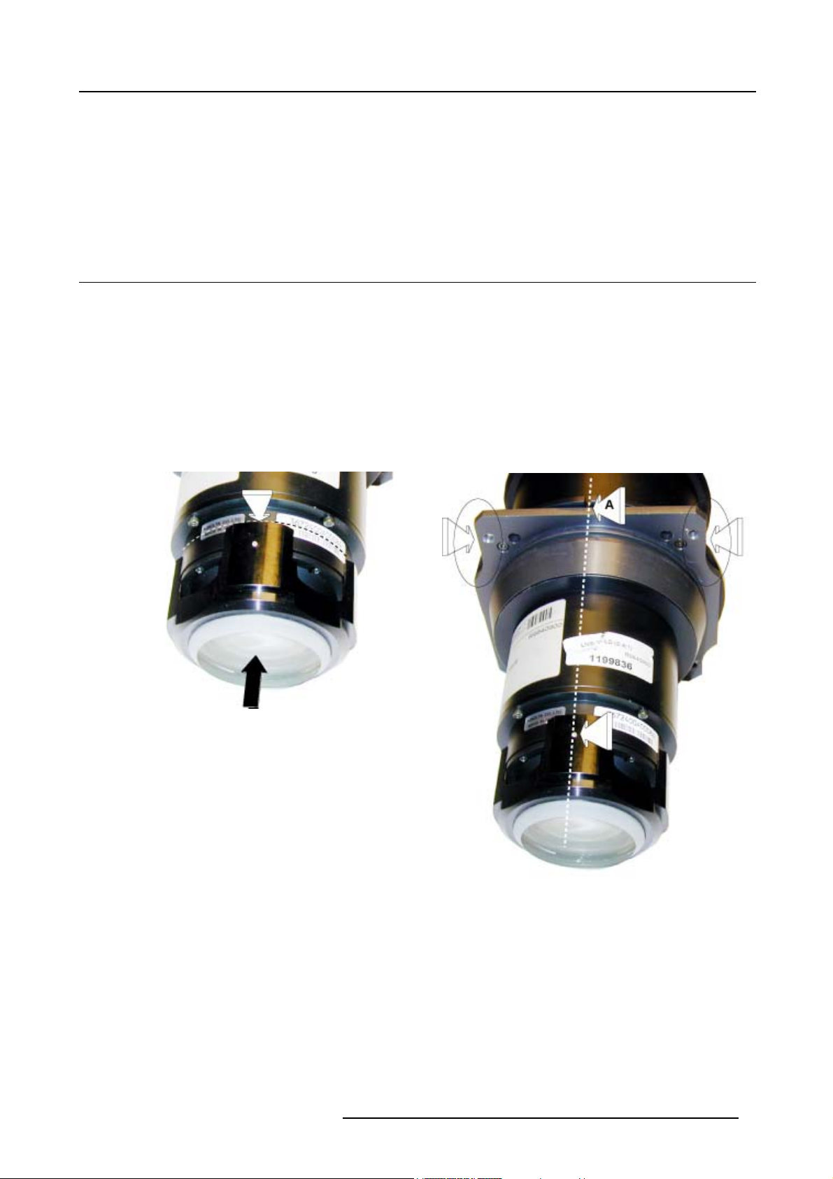
1. Carefully unpack the optical lens adapter. Avoid touching the lens itself (fingerprints).
2. Fully slide the lens adapter onto the end of the lens. (image 2-1)
3. Rotate the adapter for lining up an adapter fixation screw with the middle of the lens holder plate (A), as illustrated in picture
below. (image 2-2)
4. Secure the position of the adapter by tightening the 4 screws (B). (image 2-3)
Image 2-1
Lens adapter insertion
Image 2-2
Lens adapter lining up
R5976641 OPTICAL LENS ADAPTER 29/03/2004 5
Page 10

2. Mounting the Optical Lens Adapter
Image 2-3
Lens adapter securing
2.2 TLD Zoom Lenses and CineVERSUM Cinema zoom Lenses
Necessary tools
Small flat (0.5 mm) screwdriver
How to Mount The Optical Lens Adapter
1. Carefully unpack the optical lens adapter. Avoid touching the lens itself (fingerprints).
2. Fully slide the lens adapter onto the end of the lens. (image 2-4)
3. Rotate the adapter for lining up an adapter fixation screw with the middle of the lens holder plate (A), as illustrated in picture
below. (image 2-5)
4. Secure the position of the adapter by tightening the 3 screws (B). (image 2-6)
Image 2-4
Lens adapter insertion
Image 2-5
Lens adapter lining up
6 R5976641 OPTICAL LENS ADAPTER 29/03/2004
Page 11

Image 2-6
Lens adapter securing
2. Mounting the Optical Lens Adapter
R5976641 OPTICAL LENS ADAPTER 29/03/2004 7
Page 12

2. Mounting the Optical Lens Adapter
8 R5976641 OPTICAL LENS ADAPTER 29/03/2004
Page 13

3. Lens Removal and Installation
3. LENS REMOVAL AND INSTALLATION
Overview
• Lens Removal
• Lens Installation
3.1 Lens Removal
Necessary tools
No tools.
CAUTION: Risk of personalinjury and lens damage. Pay attention to lenssupport while removing orins
the lens.
How to remove the installed lens
1. Support the lens with one hand.
2. Fully move the handle (A) of the lens anchor system counter clockwise (unlocked).
3. Remove the lens unit. (image 3-1)
Image 3-1
Lens removal
talling
3.2 Lens Installation
How t o install the new lens
1. Fully move the lens handle clockwise (lock position).
2. Insert the lens unit into the lens holder lining up the motor connector with the its socket (B) until it fits.
3. Push the lens unit in the lens holder until it fits (a click is audible when the lens locks). (image 3-2)
R5976641 OPTICAL LENS ADAPTER 29/03/2004
9
Page 14

3. Lens Removal and Installation
Image 3-2
Lens installation
CAUTION: For a table mounted projector, block the projector while inserting the lens unit to a
jector from sliding off from the table.
void the pro-
10 R5976641 OPTICAL LENS ADAPTER 29/03/2004
Page 15

4. Lens Formulas
4. LENS FORMULAS
4.1 Projector Distance Calculation
Diagram
The following diagrams explains the position of the projector with respect to the screen and how to determine the projector distance
PD.
A
B
Image 4-1
PD calculation Front/Ceiling configuration
PD
C
PD
R5976641 OPTICAL LENS ADAPTER 29/03/2004 11
Page 16

4. Lens Formulas
A
PD
PD
B
Image 4-2
PD calculation Front/Table configuration
4.2 Lens Formulas
Lens Formulas for the different lenses with optical adapter
Lens formulas in the decimal system (PD and SW in meters)
TLD ( 0.8:1)
PD=1.06 x SW + 0.09
C
TLD HB(0.8:1)
PD=1.06 x SW + 0.09
TLD (1.6-2.0):1
TLD (1.6-2.0):1 Wide PD=2.01 x SW - 0.05
TLD (1.6-2.0):1 Tele PD=2.53 x SW - 0.09
TLD HB(1.6-2.0):1
TLD (1.6-2.0):1 Wide PD=2.01 x SW - 0.05
TLD (1.6-2.0):1 Tele PD=2.53 x SW - 0.09
12 R5976641 OPTICAL LENS ADAPTER 29/03/2004
Page 17

TLD (2.0-2.8):1
TLD HB(2.0-2.8):1
TLD (2.8-5.0):1
TLD HB(2.8-5.0):1
TLD (5.0-8.0):1
4. Lens Formulas
TLD (2.0-2.8):1 Wide PD=2.52 x SW - 0.13
TLD (2.0-2.8):1 Tele PD=3.58 x SW - 0.20
TLD (2.0-2.8):1 Wide PD=2.52 x SW - 0.13
TLD (2.0-2.8):1 Tele PD=3.58 x SW - 0.20
TLD (2.8-5.0):1 Wide PD=3.53 x SW - 0.12
TLD (2.8-5.0):1 Tele PD=6.43 x SW - 0.33
TLD (2.8-5.0):1 Wide PD=3.53 x SW - 0.12
TLD (2.8-5.0):1 Tele PD=6.43 x SW - 0.33
TLD (5.0-8.0):1 Wide PD=6.18 x SW +0.03
TLD (5.0-8.0):1 Tele PD=10.29 x SW - 0.24
TLD HB(5.0-8.0):1
TLD (5.0-8.0):1 Wide PD=6.18 x SW +0.03
TLD (5.0-8.0):1 Tele PD=10.29 x SW - 0.24
CineVERSUM Cinema (1.6-2.0):1
CineVERSUM Cinema (1.6-2.0):1 Wide PD=1.62 x SW - 0.07
CineVERSUM Cinema (1.6-2.0):1 Tele PD=2.03 x SW - 0.11
CineVERSUM Cinema (2.0-2.8):1
CineVERSUM Cinema (2.0-2.8):1 Wide PD=2.03 x SW - 0.15
CineVERSUM Cinema (2.0-2.8):1 Tele PD=2.88 x SW - 0.22
CineVERSUM Cinema (2.8-5.0):1
CineVERSUM Cinema (2.8-5.0):1 Wide PD=2.84 x SW - 0.14
CineVERSUM Cinema (2.8-5.0):1 Tele PD=5.18 x SW - 0.36
CineVERSUM Cinema (5.0-8.0):1
CineVERSUM Cinema (5.0-8.0):1 Wide PD=4.97 x SW - 0.01
CineVERSUM Cinema (5.0-8.0):1 Tele PD=8.28 x SW - 0.270.016*39.37
Lens Formulas for the different lenses with optical adapter
Lens formulas in the inch system (PD and SW in inches)
R5976641 OPTICAL LENS ADAPTER 29/03/2004
13
Page 18

4. Lens Formulas
TLD ( 0.8:1)
TLD HB(0.8:1)
TLD (1.6-2.0):1
TLD HB(1.6-2.0):1
TLD (2.0-2.8):1
PD=1.06 x SW + 3.54
PD=1.06 x SW + 3.54
TLD (1.6-2.0):1 Wide PD=2.01 x SW - 1.97
TLD (1.6-2.0):1 Tele PD=2.53 x SW - 3.54
TLD (1.6-2.0):1 Wide PD=2.01 x SW - 1.97
TLD (1.6-2.0):1 Tele PD=2.53 x SW - 3.54
TLD (2.0-2.8):1 Wide PD=2.52 x SW - 5.12
TLD (2.0-2.8):1 Tele PD=3.58 x SW - 7.87
TLD HB(2.0-2.8):1
TLD (2.8-5.0):1
TLD HB(2.8-5.0):1
TLD (5.0-8.0):1
TLD HB(5.0-8.0):1
TLD (2.0-2.8):1 Wide PD=2.52 x SW - 5.12
TLD (2.0-2.8):1 Tele PD=3.58 x SW - 7.87
TLD (2.8-5.0):1 Wide PD=3.53 x SW - 4.72
TLD (2.8-5.0):1 Tele PD=6.43 x SW - 12.99
TLD (2.8-5.0):1 Wide PD=3.53 x SW - 4.72
TLD (2.8-5.0):1 Tele PD=6.43 x SW - 12.99
TLD (5.0-8.0):1 Wide PD=6.18 x SW + 1.18
TLD (5.0-8.0):1 Tele PD=10.29 x SW - 9.45
TLD (5.0-8.0):1 Wide PD=6.18 x SW + 1.18
TLD (5.0-8.0):1 Tele PD=10.29 x SW - 9.45
CineVERSUM Cinema (1.6-2.0):1
CineVERSUM Cinema (1.6-2.0):1 Wide PD=1.62 x SW - 2.91
CineVERSUM Cinema (1.6-2.0):1 Tele PD=2.03 x SW - 4.49
14 R5976641 OPTICAL LENS ADAPTER 29/03/2004
Page 19

CineVERSUM Cinema (2.0-2.8):1
CineVERSUM Cinema (2.0-2.8):1 Wide PD=2.03 x SW - 6.06
CineVERSUM Cinema (2.0-2.8):1 Tele PD=2.88 x SW - 8.82
CineVERSUM Cinema (2.8-5.0):1
CineVERSUM Cinema (2.8-5.0):1 Wide PD=2.84 x SW - 5.57
CineVERSUM Cinema (2.8-5.0):1 Tele PD=5.18 x SW - 14.33
CineVERSUM Cinema (5.0-8.0):1
CineVERSUM Cinema (5.0-8.0):1 Wide PD=4.97 x SW + 0.24
CineVERSUM Cinema (5.0-8.0):1 Tele PD=8.28 x SW - 10.79
4. Lens Formulas
R5976641 OPTICAL LENS ADAPTER 29/03/2004 15
Page 20

4. Lens Formulas
16 R5976641 OPTICAL LENS ADAPTER 29/03/2004
Page 21

5. LENS ADJUSTMENT
Lens adjustment features:
The lens adjustment menu contains the following items:
• Zoom/Focus adjustment of the lens
• Vertical and Horizontal shift of the image.
• Activation of a specific test pattern for lens adjustment.
Lens adjustment via Control Buttons on projector only possible for RLM series.
Overview
• Lens Adjustment via Control Buttons on Projector
• Lens Adjustment via Menu Bar
• Direct Lens Adjustment (RCU)
5.1 Lens Adjustment via Control Buttons on Projector
5. Lens Adjustment
How to enter the adjustment menu.
1. Press the control button
The lens adjustment menu appears on the screen, requesting for ZOOM/FOCUS alignment.
2. Press button
Note: For the alignment, a lens adjustment test pattern can be activated: toggle control button
the lens adjustment test pattern.
3. Press the corresponding arrows (A1) or (A2) on the adjust button, as indicated in front of the menu items, for alignment.
4. Press control button
1
A2
A1
D
Lens
(C).
(B) to toggle between ZOOM/FOCUS and Vert. Hor. SHIFT menu.
(D) to leave the lens adjustment menu. (image 5-1)
2
Lens adjustment
Use
↑
and ↓ for vertical shift
Use
←
and → for horizontal shift
Press <enter> for ZOOM/FOCUS
Press <LOGO> or <LENS>
B
C
for test pattern
Lens adjustment
Use
↑
and ↓ for zoom
←
and → for focus
Use
Press <enter> for SHIFT mode
Press <LOGO> or <LENS>
for test pattern
3
Lens adjustment
Use
↑
and ↓ for vertical shift
Use ← and → for horizontal shift
Press <enter> for ZOOM/FOCUS
Press <LOGO> or <LENS>
for test pattern
Lens adjustment
Use ↑ and ↓ for zoom
Use ← and → for focus
Press <enter> for SHIFT mode
Press <LOGO> or <LENS>
for test pattern
Lens
(C) to activate or deactivate
Image 5-1
Lens Adjustment
1 Button panel on projector
2 Menu Zoom/Focus and Vertical & Horizontal shift
3 Same menus inserted in lens adjustment test pattern
R5976641 OPTICAL LENS ADAPTER 29/03/2004
17
Page 22

5. Lens Adjustment
5.2 Lens Adjustment via Menu Bar
How to enter the adjustment menu.
1. Press the MENU button (A) on the Remote Control.
The menu bar (1) appears on top of the image. (image 5-2)
2. Press → (A1) on adjust button to select menu item Installation.
A text box appears with the first item Lens adjustment selected (reversed text)
3. Press ENTER button (B) to activate the lens adjustment menu (2).
The lens adjustment menu appears on the screen, requesting for ZOOM/FOCUS alignment.
4. Press ENTER button (B) to toggle between ZOOM/FOCUS and Vert. Hor. SHIFT menu (2).
Note: For the alignment, a lens adjustment test pattern can be activated: toggle button (C) to activate or deactivate the lens
adjustment test pattern (3).
5. Press the corresponding arrows (A1) or (A2) on the adjust button, as indicated in front of the menu items, for alignment.
6. Press control button (D) to leave the lens adjustment menu.
...... Installation ......
1
2
Lens adjustment
D
A1
A
A2
B
C
Use
↑
and ↓ for vertical shift
←
and → for horizontal shift
Use
Press <enter> for ZOOM/FOCUS
Press <LOGO> or <LENS>
for test pattern
Lens adjustment
Use
↑
←
Use
Press <enter> for SHIFT mode
Press <LOGO> or <LENS>
for test pattern
Lens adjustment
Projector address
......
and ↓ for zoom
and → for focus
3
Lens adjustment
Use
↑
and ↓ for vertical shift
←
and → for horizontal shift
Use
Press <enter> for ZOOM/FOCUS
Press <LOGO> or <LENS>
for test pattern
Lens adjustment
Use ↑ and ↓ for zoom
Use ← and → for focus
Press <enter> for SHIFT mode
Press <LOGO> or <LENS>
for test pattern
Image 5-2
Lens adjustment via menu
5.3 Direct Lens Adjustment (RCU)
Lens adjustment button on the Remote Control
On the Remote Control three buttons with double action are provided, allowing direct alignment for lens ZOOM, FOCUS and VERTICAL SHIFT (For Horizontal Shift, see the first t
1. Press LENS ZOOM button [-] or [+] (A) for correct image size on the screen.
2. Press LENS FOCUS button [-] or [+] (C) for an overall
3. Press LENS SHIFT button ↑ or ↓ (B) for correct vertical position of the image on the screen. (image 5-3)
Image 5-3
Lens adjustment with RCU
wo procedures).
focus of the image.
B
A
C
18 R5976641 OPTICAL LENS ADAPTER 29/03/2004
Page 23

6. LENS CLEANING
6.1 Cleaning the lens
To minimize the possibility of damaging the optical coati ng or scratching exposed lens surface, we have developed recommenda ti ons for cleaning the lens. FIRST, we recommend you try to remove any material from
the lens by blowing it o ff with clean, dry deionized air. DO NOT use any liqu id to clean the lenses.
Necessary tools
To ra ys e eTMcloth (delivered together with the lens kit). Order number : R379058.
Howtocleanthelens?
Proceed as follow :
1. Always wipe lenses with a CLEAN Toraysee
2. Always wipe lenses in a single direction.
Warning: Do not wipe back and forwards across the lens surface as this tends to grind dirt into the coating.
3. Do not leave cleaning cloth in either an open room or lab coat pocket, as doing so can contaminate the cloth.
4. If smears occur when cleaning lenses, replace the cloth. Smears are the first indication of a dirty cloth.
TM
cloth.
6. Lens Cleaning
WARNING: Do not use fabric softener when washing the cleaning cloth or softener sheets when drying the
cloth.
Do not use liquid cleaners on the cloth as doing so will contaminate the cloth.
CAUTION: Other lenses can also be cleaned safely with this Toraysee
TM
cloth.
R5976641 OPTICAL LENS ADAPTER 29/03/2004 19
Page 24

6. Lens Cleaning
20 R5976641 OPTICAL LENS ADAPTER 29/03/2004
Page 25

INDEX
Index
A
Adjustment 17–18
Lens 17–18
Remote Control 18
Via Menu Bar 18
With Control buttons 17
C
Calculation PD 11
Projector distance 11
CineVERSUM cinema zoom lenses 6
Mounting adapter 6
Cleaning 19
Lens 19
F
Formulas 11–12
Lens 12
Lenses 11
K
Kit Contents 3
L
Lens 3, 9, 12, 17–19
Adjustment 17–18
Remote Control 18
Via Menu Bar 18
With Control buttons 17
Cleaning 19
Formulas 12
Installation 9
Optical adapter 3
Removal 9
Lens installation 9
Lens removal 9
Lenses 11
Formulas 11
M
Mounting 5
Optical Lens adapter 5
Mounting adapter 5–6
CineVERSUM cinema zoom lenses 6
TLD (0.8:1) lens 5
TLD HB(0.8:1) lens 5
TLD zoom lenses 6
O
Optical adapter 3
Lens 3
optical Lens adapter 3
Use 3
Optical Lens adapter 5
Mounting 5
P
Projector distance 11
Calculation PD 11
R
Remote Control 18
Lens adjustment 18
T
TLD (0.8:1) lens 5
Mounting adapter 5
TLD HB(0.8:1) lens 5
Mounting adapter 5
TLD zoom lenses 6
Mounting adapter 6
U
Use of the optical lens adapter 3
R5976641 OPTICAL LENS ADAPTER 29/03/2004
21
Page 26

Index
22 R5976641 OPTICAL LENS ADAPTER 29/03/2004
Page 27

Revision Sheet
To :
Barco nv Events/Documentation
Noordlaan 5, B-8520 Kuurne
Phone: +32 56.36.89.70, Fax: +32 56.36.88.24
E-mail: antoon.dejaegher@barco.com, Web: www.barco.com
From:
Date:
Please correct the following points in this documentation (R5976641/01):
page
wrong
correct
R5976641 OPTICAL LENS ADAPTER 29/03/2004
 Loading...