

Page 1
SIMULATION PRODUCTS
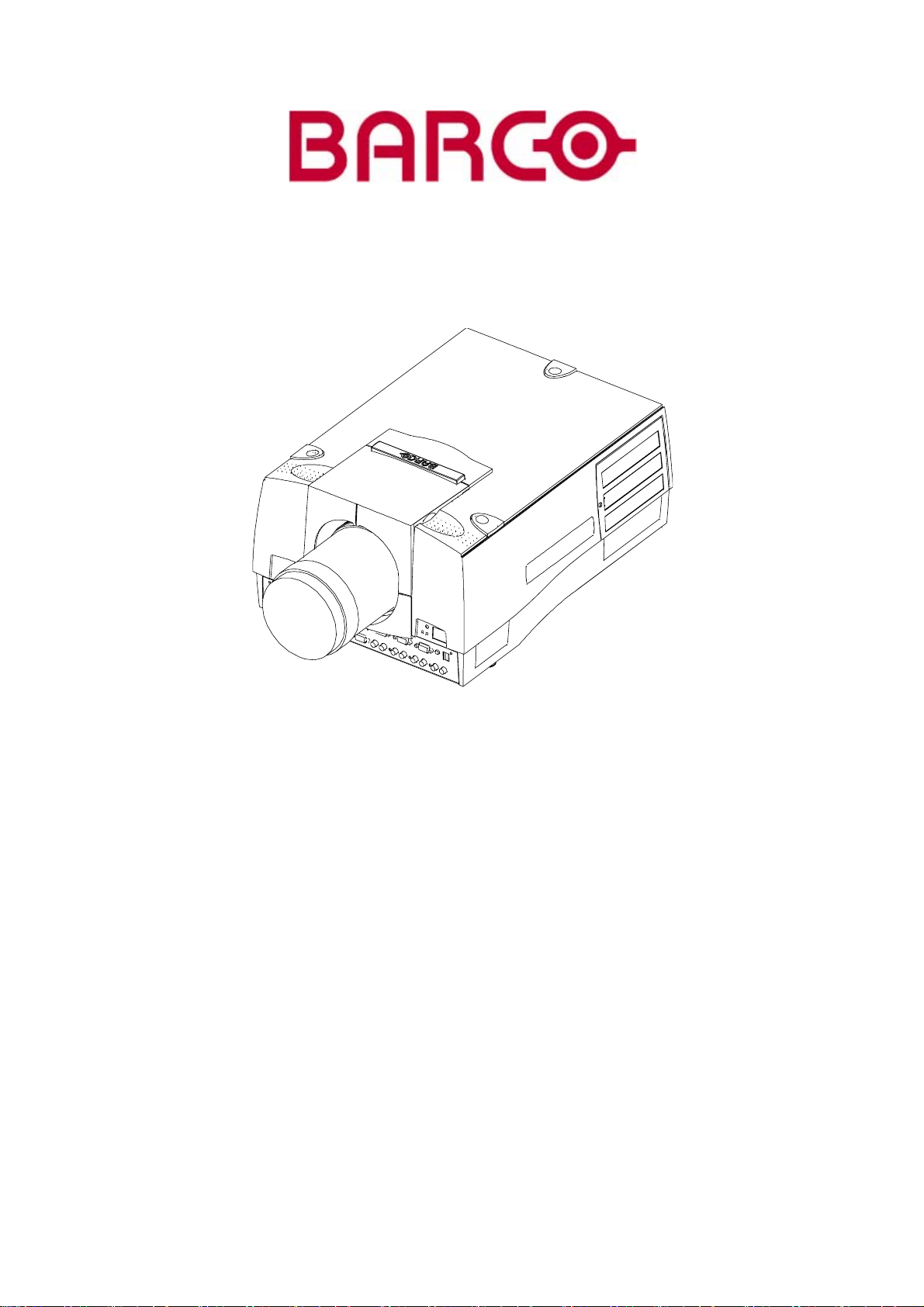
BARCOREALITY SIM 6MKII
R9040142
R9040143
OWNER’S MANUAL
08092003 R5976493/02
Page 2

Barco nv Simulation Products
600 Bellbrook Ave, Xenia OH 45385
Phone: +1 (937) 372 7579
Fax: +1 (937) 372 8645
E-mail: eis@barco.com
Visit us at the web: www.eis.barco.com
Barco nv Simulation Products
laan 5, B-8520 Kuurne
Noord
Phone: +32 56.36.82.11
Fax: +32 56.36.84.86
info@barco.com
E-mail:
Visit us at the web: www.barco.com
Printed in Belgium
Page 3

Copyright ©
All rights reserved. No part of this document may be copied, reproduced or translated. It shall not otherwise be recorded, transmitted or
stored in a retrieval system without the prior written consent of Barco.
Changes
Barco provides this manual ’as is’ without warranty of any kind, either expressed or implied, including but not limited to the implied warranties or merchantability and fitness for a particular purpose. Barco may make improvements and/or changes to the product(s) and/or the
program(s) described in this publication at any time without notice.
This publication could contain technical inaccuracies or typographical errors. Changes are periodically made to the information in this
publication; these changes are incorporated in new editions of this publication.
Trademarks
Brand and product names mentioned in this manual may be trademarks, registered trademarks or copyrights of their respecti
All brand and product names mentioned in this manual serve as comments or examples and are not to be understood as advertising for
the products or their manufactures.
ve holders.
Federal Communications Commission (FCC Statement)
This equipment has been tested and found to comply with the limits for a class A digital device, pursuant to Part 15 of the FCC rules.
These limits are designed to provide reasonable protection against harmful interference when the equipment is operated in a commercial
environment. This equipment generates, uses, and can radiate radio frequency energy and, if not installed and used in accordance with
the instruction manual, may cause harmful interference to radio communications. Operation of this equipment in a residential area may
cause harmful interference, in which case the user will be responsible for correcting any interference.
Page 4

Page 5

Table of contents
TABLE OF CONTENTS
1. Packaging and Dimensions ....................................................................................... 5
1.1 Lens Packaging . . ..................................................................................................................... 5
1.2 Dimensions............................................................................................................................ 5
2. Installation Guidelines.............................................................................................. 7
2.1 Installation guidelines ................................................................................................................. 7
2.2 Configuration .......................................................................................................................... 8
2.3 Lenses . ................................................................................................................................ 9
2.3.1 Lenses . . .. . ....................................................................................................................10
2.3.2 Lens formulas . . . ...............................................................................................................10
2.3.3 Lens installation ............................................................................................................... 11
2.3.4 Cleaning the lens . . . ...........................................................................................................12
2.4 Batteries..............................................................................................................................12
2.4.1 Battery installation.............................................................................................................12
3. Connections.........................................................................................................13
3.1 Power connections ................................................................................................................... 13
3.2 Switching on..........................................................................................................................13
3.3 Switching to standby .. ...............................................................................................................15
3.4 Switching off..........................................................................................................................15
3.5 Input source connection. . ............................................................................................................15
3.5.1 Input facilities . . . ...............................................................................................................15
3.5.2 Inputs via RCVDS05...........................................................................................................16
3.5.3 5–Cable input .. . ...............................................................................................................16
3.5.4 Computer input . ............................................................................................................... 18
3.5.5 S-Video Input (optional) . .. .................................................................................................... 19
3.5.6 SDI input / SDI output (optional) . .............................................................................................20
3.6 Communications connections. . . . ....................................................................................................20
3.6.1 RS232..........................................................................................................................20
4. Getting started......................................................................................................21
4.1 RCU& Local keypad.................................................................................................................21
4.2 Terminology overview ................................................................................................................21
4.3 Operating theprojector...............................................................................................................23
4.3.1 Switching on................................................................................................................... 23
4.4 Quick setupadjustments.............................................................................................................24
4.4.1 Quick lensAdjustment.........................................................................................................24
4.4.2 Quick onScreen ColorChange. ..............................................................................................25
4.5 Using the RCU .......................................................................................................................26
4.6 Projector Address.................................................................................................................... 28
4.6.1 Controlling theprojector....................................................................................................... 28
4.6.2 Displaying andProgrammingaddresses ..................................................................................... 29
4.7 Controlling theprojector..............................................................................................................29
5. Random Access ....................................................................................................31
5.1 Random AccessOverview ..........................................................................................................31
5.2 Random AccessStart up ............................................................................................................32
5.3 FileServices.......................................................................................................................... 32
5.3.1 File annotation .. ...............................................................................................................32
5.3.2 Possible filemanipulations....................................................................................................33
5.3.3 Start up of the fileservices....................................................................................................33
5.3.4 Load file .. . . . ................................................................................................................... 34
5.3.5 Edit file .........................................................................................................................35
5.3.5.1 Start up..................................................................................................................35
5.3.5.2 Changing the settings. .. ................................................................................................35
5.3.5.3 Correct value............................................................................................................ 36
5.3.5.4 Rename . ................................................................................................................38
5.3.5.5 Copy.....................................................................................................................39
5.3.5.6 Delete....................................................................................................................39
5.3.5.7 File options..............................................................................................................40
5.4 Picture tuning......................................................................................................................... 42
5.4.1 Start up.........................................................................................................................42
5.4.2 Motion Compensation (TMR) (Optional)......................................................................................42
5.4.2.1 Starting up Motion Compensation ..................................................................................... 43
5.4.2.2 LCD speed . . ............................................................................................................43
5.4.2.3 LCD speed R/G . . . . . .................................................................................................... 43
5.4.2.4 LCD speed B/G . .. . . ....................................................................................................44
5.4.3 Color Temperature.............................................................................................................44
5.4.4 Gamma ........................................................................................................................45
5.4.5 Decoding (Optional) ...........................................................................................................46
5.4.6 Color Depth ....................................................................................................................46
5.4.7 Input Balance . . ................................................................................................................46
5.4.8 Black Color.....................................................................................................................49
R5976493 BARCOREALITY SIM 6 MK II 08092003
1
Page 6

Table of contents
5.5 Audiotuning(Optional)............................................................................................................... 50
5.5.1 Start up.........................................................................................................................50
5.5.2 Volume, Balance,Bass andTreble ........................................................................................... 50
5.5.3 Mute............................................................................................................................50
5.5.4 Fade............................................................................................................................ 51
5.5.5 Mode...........................................................................................................................51
5.5.6 Video - audio lock. . . ...........................................................................................................52
5.6 Geometry.............................................................................................................................52
5.6.1 Introduction .................................................................................................................... 53
5.6.2 Geometry start up .............................................................................................................53
5.6.3 Shift ............................................................................................................................53
5.6.4 Size ............................................................................................................................ 53
5.6.5 Side Keystone .................................................................................................................54
5.6.6 Blanking........................................................................................................................54
5.6.7 Aspect Ratio ...................................................................................................................55
5.6.8 Options.........................................................................................................................55
5.7 SoftEdge ............................................................................................................................ 56
5.7.1 Starting up the soft edge . . ....................................................................................................56
5.7.2 Type............................................................................................................................57
5.7.3 Size ............................................................................................................................ 58
5.7.4 Options.........................................................................................................................58
5.8 Demo .................................................................................................................................58
5.8.1 Start up.........................................................................................................................58
5.8.2 Split Screen.................................................................................................................... 59
6. Installation Mode ...................................................................................................61
6.1 Installation ModeOverview..........................................................................................................62
6.2 Build-up...............................................................................................................................62
6.3 Startup ...............................................................................................................................63
6.4 Input slots. .. ..........................................................................................................................63
6.5 No signal.............................................................................................................................. 64
6.5.1 Changing the background color .. .............................................................................................64
6.5.2 Changing the shutdown setting . . . ............................................................................................65
6.5.3 Changing the shutdown time .. ................................................................................................65
6.6 Lens adjustment. .. ...................................................................................................................65
6.7 MenuPosition ........................................................................................................................ 67
6.8 Quickaccess keys ...................................................................................................................67
6.8.1 What areQuick Access Keys?................................................................................................ 67
6.8.2 Getting anoverview ...........................................................................................................68
6.9 800- Peripheral .. . . ...................................................................................................................68
6.9.1 Defining the Output module of the RCVDS05 . . . ............................................................................. 68
6.9.2 Defining the communicationprotocol of the RCVDS05...................................................................... 69
6.10 Configuration ......................................................................................................................... 69
6.11 OSD Color............................................................................................................................70
6.12 Internal Patterns...................................................................................................................... 70
6.13 Shutter (Optional) . ................................................................................................................... 71
7. ServiceMode........................................................................................................73
7.1 Service ModeOverview..............................................................................................................73
7.2 Build-up...............................................................................................................................74
7.3 Startup ...............................................................................................................................74
7.4 Identification .......................................................................................................................... 74
7.4.1 The different identification screens .. . . .. ..................................................................................... 74
7.4.2 Displaying the identification screen . . .. . ......................................................................................75
7.5 Change password.................................................................................................................... 75
7.6 Change the address..................................................................................................................76
7.6.1 Start up.........................................................................................................................76
7.6.2 Projector Address.............................................................................................................. 77
7.7 Change Baudrate . ................................................................................................................... 77
7.8 Resetlamp runtime ..................................................................................................................77
7.9 LampRuntimehistory................................................................................................................78
7.10 Dimming ..............................................................................................................................79
7.10.1 Lamp Dimming.................................................................................................................79
7.10.2 Constant Light Output (Optional). . ............................................................................................79
7.11 Barco logo ............................................................................................................................80
7.12 Panel adjustments ................................................................................................................... 81
7.13 Uniformity............................................................................................................................. 81
7.14 PresetInput Balance.................................................................................................................81
7.15 Electronic convergence . . . ...........................................................................................................82
7.16 I2C Diagnoses . . . . ....................................................................................................................82
A. Standard Source setup files ......................................................................................85
A.1 Table overview .......................................................................................................................85
B. Source Numbers 81 — 86 and 91 — 96.........................................................................89
B.1 Projector without any 800 peripheral connected . . . ................................................................................. 89
B.2 Projector with a 800 peripheral connected .. . . ......................................................................................89
2 R5976493 BARCOREALITY SIM 6 MK II 08092003
Page 7

Table of contents
B.2.1 Sourcenumbers 91— 96.....................................................................................................89
B.2.2 Sourcenumbers 81— 86.....................................................................................................90
C. Cleaning the Dustfilter.............................................................................................91
C.1 Cleaning ..............................................................................................................................91
Index......................................................................................................................93
R5976493 BARCOREALITY SIM 6 MK II 08092003 3
Page 8

Table of contents
4 R5976493 BARCOREALITY SIM 6 MK II 08092003
Page 9

1. PACKAGING AND DIMENSIONS
This chapter handles about the way the projector is packed and gives an overview of the dimensions.
• Lens Packaging
• Dimensions
1.1 Lens Packaging
Way of Packaging
Lenses are supplied as an individual item.
Theyarepackedinacartonbox.
Save the original shipping carton and packing material, they will be necessary if you ever have to transport
the lens.
Never transport the projector with the lens mounted on it !
Always remove the lens before transporting the projector.
1. Packaging and Dimensions
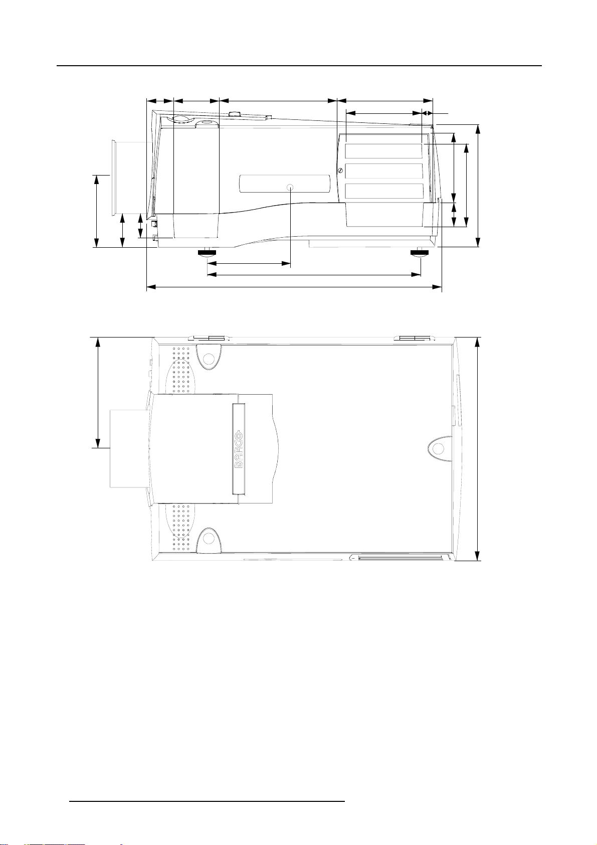
1.2 Dimensions
Dimensions overview
Dimensions are given in mm (1 inch = 25.4 mm)
53.5
120.2
245.1
97.6
371.2
202.4
187.2
53.5
29.6
107.5
6
152.6
min 12
max 24
Image 1-1
Front view dimensions projector
R5976493 BARCOREALITY SIM 6 MK II 08092003 5
152.6
Page 10
1. Packaging and Dimensions
46 82.7 211.4
124.1
43
60
Image 1-2
Side view dimensions projector
148.9
526.8
380.6
169.5
139.6
14
124.4
147.8
42
217.2
184.4
Image 1-3
Top view dimensions p rojector
368.7
6 R5976493 BARCOREALITY SIM 6 MK II 08092003
Page 11
2. INSTALLATION GUIDELINES
Overview
• Installation guidelines
• Configuration
• Lenses
• Batteries
Before installing the projector, read first the safety instructions supplied with the BarcoReality SIM6 MKII.
2.1 Installation guidelines
Ambient Temperature Conditions
Careful consideration of things such as image size, ambient light level, projector placement and ty
the optimum use of the projection system.
Max. ambient temperature : 40 °C or 104 °F
Min. ambient temperature : 0 °C or 32 °F
The projector will not operate if ambient air temperature falls outside this range (0°C- 40°C or 32°F-104°F).
Storage temperature: -35°C to +65°C (-25.6°F to 149°F)
2. Installation Guidelines
pe of screen to use are critical to
Humidity Conditions
Storage: 0 to 98 % RH Non-condensing
Operation: 0 to 95 % RH Non-condensing
Environment
Do not install the projection system in a site near heat sources such as radiators or air ducts, or in a place subject to direct sunlight,
excessive dust or humidity. Be aware that room heat rises to the ceiling; check that temperature near the installation site is not
excessive.
Harmful Environmental Contamination Precaution
Environment condition check
A projector must always be mounted in a manner which ensures the free flow of clean air into the projectors ventilation inlets. For
installations in environments where the projector is subject to airborne contaminants such as that produced by smoke machines or
similar (these deposit a thin layer of greasy residue upon the projectors internal optics and imaging electronic surfaces, degrading
performance), then it is highly advisable and desirable to have this contamination removed prior to it reaching the projectors clean
air supply. Devices or structures to extract or shield contaminated air well away from the projector are a prerequisite, if this is not a
feasible solution then measures to relocate the projector to a clean air environment should be considered.
Only ever use the manufactures recommended cleaning kit which has been specifically designed for cleaning optical parts, never
use industrial strength cleaners on a projectors optics as these will degrade optical coatings and damage sensitive optoelectronic
components. Failure to take suitable precauti
nants will culminate in extensive and irreversible ingrained optical damage. At this stage cleaning of the internal optical units will be
non-effective and impracticable. Damage of this nature is under no circumstances covered under the manufactures warranty and
may deem the warranty null and void. In such a c
repair. It is the clients responsibility to ensure at all times that the projector is protected from the harmful effects of hostile airborne
particles in the environment of the projector. The manufacture reserves the right to refuse repair if a projector has been subject to
wantful neglect, abandon or improper
ons to protect the projector from the effects of persistent and prolonged air contami-
ase the client shall be held solely responsible for all costs incurred during any
use.
What about ambient light ?
The ambient light level of any room is made up of direct or indirect sunlight and the light fixtures in the room. The amount of ambient
light will determine how bright the image will appear. So, avoid direct light on the screen. Windows that face the screen should be
covered by opaque drapery while the set is being viewed. It is desirable to install the projection system in a room whose walls and
floor are of non-reflecting material. The use of recessed ceiling lights and a method of dimming those lights to an acceptable level
R5976493 BARCOREALITY SIM 6 MK II 08092003
7
Page 12

2. Installation Guidelines
is also important. Too much ambient light will ‘wash out’ of the projected image. This appears as less contrast between the darkest
and lightest parts of the image. With bigger screens, the ‘wash out’ becomes more important. As a general rule, darken the room to
the point where there is just sufficient light to read or write comfortably. Spot lighting is desirable for illuminating small areas so that
interference with the screen is minimal.
Which screen type ?
There are two major categories of screens used for projection equipment. Those used for front projected images and those for rear
projection applications.
Screens are rated by how much light they reflect (or transmit in the case of rear projection systems) given a determined am
of light projected toward them. The ‘GAIN’ of a screen is the term used. Front and rear screens are both rated in terms of gain.
The gain of screens range from a white matte screen with a gain of 1 (x1) to a brushed aluminized screen with a gain of 10 (x10)
or more. The choice between higher and lower gain screens is largely a matter of personal preference and another co
called the Viewing angle. In considering the type of screen to choose, determine where the viewers will be located and go for the
highest gain screen possible. A high gain screen will provide a brighter picture but reduce the viewing angle. For more information
about screens, contact your local screen supplier. A high gain screen will provide a brighter picture but r
educe the viewing angle.
What image size ? How big should the image be ?
The projector is designed for projecting an image size (video) from 1.00m (3.3ft) to 6.00m (19.7ft) with a aspect ratio of 5 to 4.
2.2 Configuration
Which configuration can be used ?
The projector can be installed to project images in four different confi
gurations :
ount
nsideration
• Front/table
• Rear/table
• Front/ceiling
• Rear/ceiling
Positioning the projector
Drawings are given for a nominal lens position.
8
R5976493 BARCOREALITY SIM 6 MK II 08092003
Page 13
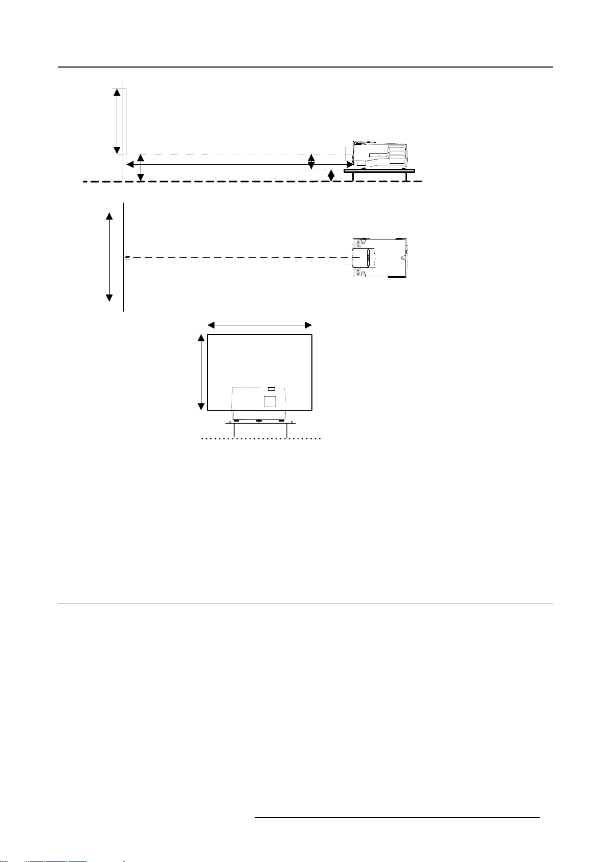
SIDE VIEW
2. Installation Guidelines
SW
SH
Screen
Screen
CD = B - A
Projector
Optical axis projection lens
B
SH
PD
Floor
TOP VIEW
SW
A
CD
Floor
BACK VIEW
Image 2-1
B Distance between ceiling and top of the screen or between floor and bottom of the screen.
A Correction value, distance between
bottom side of projector (without feet) and middle of the lens. Value to be subtracted from
B to obtain the correct installation position. (A value is a constant value for all screen widths and type of lenses, A = 124.1 mm
or 4.89 inch)
CD Total distance between projecto
r and ceiling or projector and floor.
SW Screen width
SH Screen height (image height)
PD Projector distance, distanc
e between screen and projector
2.3 Lenses
Overview
• Lenses
• Lens formulas
• Lens installation
• Cleaning the lens
R5976493 BARCOREALITY SIM 6 MK II 08092003
9
Page 14
2. Installation Guidelines
2.3.1 Lenses
Available lenses
The following lenses are available, or will become available (contact a BARCO service center) as an option :
Lenses
QFD(1.27:1)
QFD(2.5:1)
QFD(1.4-2.1:1)
QFD(2.1-3.0:1)
QFD(3.4-4.5:1)
QFD(4.5-6.0:1)
QFD(7:1)
QGD(0.8:1) / SW: (1-1.4)m
QGD(0.8:1) / SW: (1.7-2.4)m
QGD(0.86:1)
Standard version Scheimpflug version
R9840400 R9840600
R9840290 R9840470
R9840380 R9840610
R9840390 R9840590
R9840060 R9840580
R9840100 R9840460
R9840410
—
R9829800 R9840480
R9840040 R9840490
R9840491 R9840492
2.3.2 Lens formulas
Formulas
Lenses
QFD(1.27:1) PD = 1.33 x SW — 0,0195 + 0,00270 /SWPD = 1.33 x SW — 0.768 + 4.185 / SW
Metric Formulas (meter) Inch Formulas (inch)
QFD(2.5:1) PD = 2.486 x SW + 0,025 + 0,0215 / SW PD = 2.486 x SW +0.984 + 33.325 / SW
QFD(1.4-2.1:1) PD
QFD(2.1-3.0:1) PD
QFD(3.4-4.5:1) PD
QFD(4.5-6.0:1) PD
= 1,48 x SW + 0,0287 — 0,0215 /
min
SW
= 2,25 x SW — 0,01 + 0,0195 /
PD
max
SW
= 2,18 x SW — 0,10 + 0,055 / SW
min
= 2,97 x SW + 0,10 — 0,0730 /
PD
max
SW
= 3,457 x SW — 0,115 + 0,056 /
min
SW
= 4,542 x SW — 0,133 + 0,054 /
PD
max
SW
= 4,39 x SW — 0,02 + 0,0008 /
min
SW
= 6,00 x SW + 0,15 + 0,0029 /
PD
max
SW
PD
=1.48xSW+1.13—33.325/
min
SW
= 2.25 x SW — 0.39 + 30.225/
PD
max
SW
PD
=2.18xSW—3.937+85.25/
min
SW
= 2.97 x SW + 3.937 — 113.15 /
PD
max
SW
PD
= 3.457 x SW — 4.528 + 86.80 /
min
SW
= 4.542 x SW — 5.236 + 83.70 /
PD
max
SW
PD
= 4.39 x SW — 0.787 + 1.24 / SW
min
PD
= 6.00 x SW + 5.906 + 4.495 /
max
SW
QFD(7.0:1) PD = 7,083 x SW — 0,049 + 0,061 / SW PD = 7.083 x SW —1.929 + 94.55/ SW
QGD(0.8:1) / SW: (1-1.4)m PD = 0,794 x SW — 0,048 + 0,0072 /SWPD = 0.794 x SW — 1.89 + 11.16 / SW
QGD(0.8:1) / SW: (1.7-2.4)m PD = 0,794 x SW — 0,048 + 0,0072 /SWPD = 0.794 x SW — 1.89 + 11.16 / SW
QGD(0.86:1) PD = 0,862 x SW + 0,00254 — 0,0146 /SWPD = 0.862 x SW + 0.1 — 22.63 / SW
10 R5976493 BARCOREALITY SIM 6 MK II 08092003
Page 15
Lens program to calculate the projector distance is available on the BARCO web site :
ttp://www.barco.com/projection_systems/customer_services/lens_program.asp
h
2.3.3 Lens installation
How to install ?
Follow the next procedure :
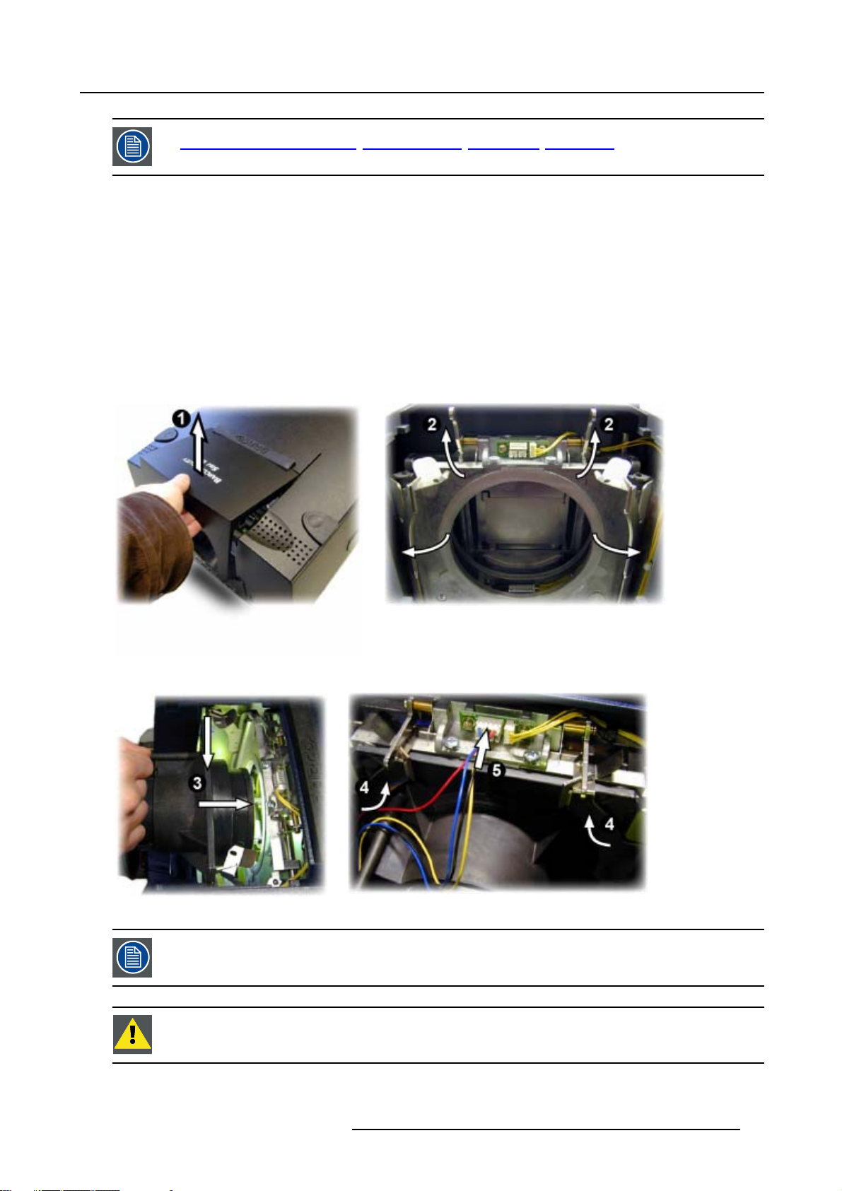
1. Open the lens cover of the projector by pivoting it up and take it off. (image 2-2)
2. Pull the lens locks levers backwards to open the lens locks. (image 2-3)
3. Put the lens on the lens holder. (image 2-4)
4. Push the lens locks back in position and lock the levers.
5. Plug the wires of the motor unit into the connector (image 2-5)
6. Re-install the lens cover.
2. Installation Guidelines
Image 2-2
Image 2-4
Image 2-3
Image 2-5
The procedure for the mounting of a Scheimpflug lens is different.
Refer to the installation manual of the lens.
Never transport the projector with the lens mounted on it !
Always remove the lens before transporting the projector.
R5976493 BARCOREALITY SIM 6 MK II 08092003 11
Page 16
2. Installation Guidelines
2.3.4 Cleaning the lens
To minimize the possibility of damaging the optical coating or scratching exposed lens surface, we have developed recommendations for cleaning the lens. FIRST, we recommend you try to remove any material from
the lens by blowing it off with clean, dry deionized air. DO NOT use any liquid to clean the lenses.
Necessary tools
To ra ys e eTMcloth (delivered together with the lens kit). Order number : R379058.
Howtocleanthelens?
Proceed as follow :
1. Always wipe lenses with a CLEAN Toraysee
2. Always wipe lenses in a single direction.
Warning: Do not wipe back and forwards across the lens surface as this tends to grind dirt into the coating.
3. Do not leave cleaning cloth in either an open room or lab coat pocket, as doing so can contaminate the cloth.
4. If smears occur when cleaning lenses, replace the cloth. Smears are the first indication of a dirty cloth.
Do not use fabric softener when washing the cleaning cloth or softener sheets when drying the cloth.
Do not use liquid cleaners on the cloth as doing so will contaminate the cloth.
TM
cloth.
Other lenses can also be cleaned safely with this TorayseeTMcloth.
2.4 Batteries
Overview
• Battery installation
2.4.1 Battery installation
How to install the battery
Two batteries are packed together with the RCU. Before using your RCU, install first these batteries.
1. Remove the battery cover on the backside by pushing the handle a little towards the bottom of the RCU.
2. Lift up the top side of the cover at the same time.
3. Insert the batteries as indicated in the RCU.
4. Put the battery cover on its place.
12
R5976493 BARCOREALITY SIM 6 MK II 08092003
Page 17
3. Connections
3. CONNECTIONS
Overview
• Power connections
• Switching on
• Switching to standby
• Switching off
• Input source connection
• Communications connections
3.1 Power connections
AC Power cord connection
Use the supplied power cord to connect your projector to the wall outlet. Plug the female power connector into the male connector
at the front of the projector. The power input is auto-ranging from 90 to 240 VAC.
Fuses
For continued protection against fire hazard :
• refer replacement to qualified service personnel.
• ask to replace with the same type of fuse (T10 AH/250V).
3.2 Switching on
How to switch on.
1. Press the power switch to switch on the projector.
- When ’0’ is visible, the projector is switched off.
- When ’1’ is visible, the projector is switched on
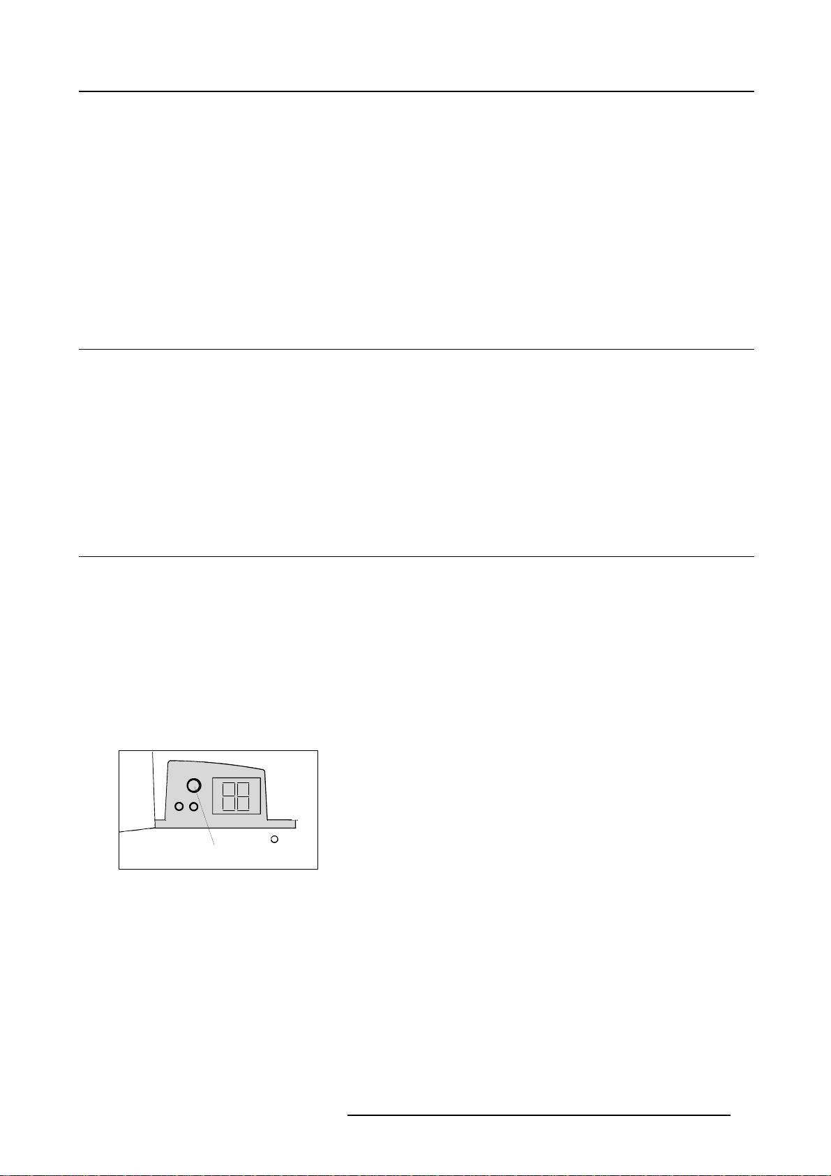
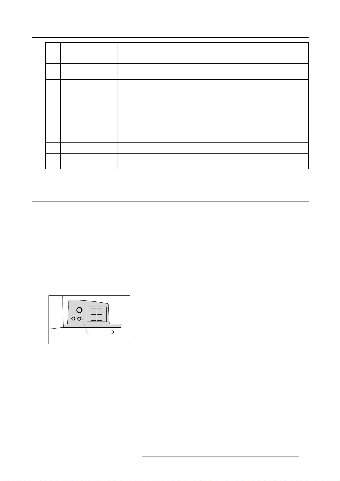
The projector starts in standby mode. The projector mode indication lamp is red.
Starting image projection.
1. Press Stand by key once on the local keypad or on the remote control.
The projector mode indication lamp will be green (image 3-1, image 3-2)
Projector mode indication
Image 3-1
R5976493 BARCOREALITY SIM 6 MK II 08092003 13
Page 18
3. Connections
Stand-by key
F3
F2
F1
F4
F5
Image 3-2
ADJ
9
7
5
3
1
0
STANDBY
8
6
4
SHARPN
2
TEXT
PHASE
ENTER
COLOR
TINT
EXIT
PAUSE
BRIGHTN
CONTRAST
PAUSE
0
9
8
7
6
5
34
2
1
TREBLE BALANCE
BASS
EXIT
ENTER
TEXT
PHASE
SHARPN
TINT
COLOR
BRIGHTN
CONTR
VOL
Lamp run time indication while running
The lamp run time warning will only be displayed when the time is exceeding the limit. A warning message will be displayed 100
hours beforehand , with the exact run time “x” displayed on the screen. This message is displayed only at the start up of the projector.
Press the EXIT button on the RCU or keypad to remove this warning message.
If the projector is running all the time the lamp warning will never be displayed.
Lamp run time is
x
hours.
Operating the lamp
longer than
x
hours
may damage
the projector.
<ENTER> to reset the
lamp runtime.
ase replace
Ple
the lamp.
-1
Menu 3
The total lifetime of the lamp for a safe operation is “x” hours max, do not use it longer. Always replace with a same type of lamp.
Call a BARCO authorized service technician for lamp replacement.
Press ENTER to reset the lamp runtime.
14
R5976493 BARCOREALITY SIM 6 MK II 08092003
Page 19
Max Lamp runtimes for the available projectors.
SIM Projector x(Maxlampruntime,inhours)
3. Connections
BarcoReality SIM6 MKII
Using a lamp for more than its recommended life time is dangerous
3.3 Switching to standby
Howtoswitchtostandby?
1. Press STANDBY for 2 seconds until the m
Saving data, please wait
Image 3-3
When switching to standby the projector waits for 30 sec. before it can be restarted. During this period the
LED display will show a jumpin
projector can restart.
3.4 Switching off
1000
as the lamp could explode.
essages Saving data please wait is displayed. (image 3-3)
g square with a dash. After one minute, two dashes will be displayed and the
How to switch off the projector?
To switch off the projector, handle as follow :
1. Press STANDBY key for 2 seconds. When the message Saving data, please wait is displayed, do not press any longer on the
STANDBY key otherwis
When switching to standby the projector waits for 1 minute before it can restart again. During this period the LED display will
show a jumping square with a dash. After one minute, two dashes will be displayed and the projector can restart.
Warning: Let cool down the proj
2. Switch off the projector with the power switch.
e the projector will restart.
ector at least 10 min.
3.5 Input source connection
3.5.1 Input facilities
Overview input facilities
• 5-cable input
• Computer
• Video (optional)
• S-Video (optional)
• Serial digital input (optional)
• IEEE (not implemented)
Input selection
This can be manually or automatically.
When ’automatic’ is selected in the Input slots menu, by starting up the projector, it searches for an input source by scanning the
inputs one by one. If only one source is found, this source will be projected. If different sources are found, the priority is as follow
R5976493 BARCOREALITY SIM 6 MK II 08092003
15
Page 20
3. Connections
1. Video
2. S-Video
3. 5 cable input
4. Computer input
SDI input is never automatically selected.
When a RCVDS is connected to the projector, the ’Automatic’ selection is disabled.
Setupoftheinputselection
1. Press ENTER to start up the adjustment mode.
2. Press the cursor keys to select Installation. (menu 3-2)
3. Press ENTER to display the Installation menu.
4. Press the cursor keys to select Input slots. (menu 3-3)
5. Press ENTER to display the Input Slots menu.
6. Press the cursor keys to select Slot Selector. (menu 3-4)
7. Press ENTER to toggle between [Manual] or [Automatic].
8. Press EXIT several times to leave the adjustment mode.
ADJUSTMENT MODE
Select a path from below :
RANDOM ACCESS
INSTALLATION
SERVICE
Select with ↑ or ↓
then <ENTER>
<EXIT> to return
Menu 3-2
Menu 3-3
INSTALLATION
INPUT SLOTS
NO SIGNAL
LENS
MENU POSITION
QUICK ACCESS KEYS
800 PERIPHERAL
MORE..
Select with ↑ or ↓
then <ENTER>
<EXIT> to return
INPUT SLOTS
SLOT SELECTOR [Automatic]
x 1. RGB [HS&VS]
- 2. RGB [HS&VS]
- 3. VIDEO
- 4. S-VIDEO
- 5. NO MODULE
- 6. NO MODULE
Select with ↑ or ↓
<ENTER> to toggle
<EXIT> to return
Menu 3-4
3.5.2 Inputs via RCVDS05
Overview
When using a RCVDS05, it is recommended to use a 5-cable output module in the RCVDS. The outputs of this module have to be
connected to the 5 cable input (slot 1) of the projector. To switch the projector in the 5-cable mode see chapter ’Installation mode’.
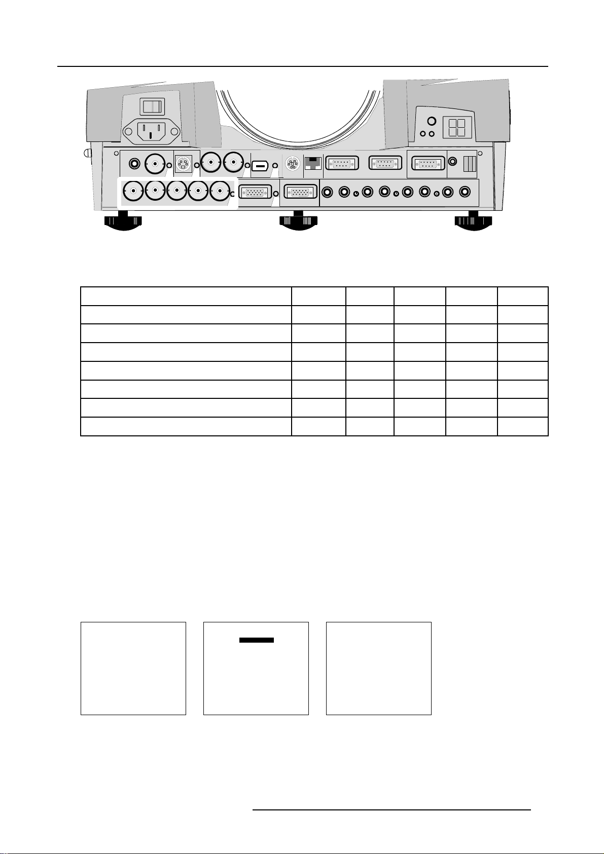
3.5.3 5–Cable input
Wheretofind?
Slot 1 has 5 BNC input terminals. These are in the left corner on the front panel.
16
R5976493 BARCOREALITY SIM 6 MK II 08092003
Page 21
3. Connections
Image 3-4
VIDEO
GB H/C
R
S-VIDEO
43
SDI
SDO
1
V
5
IEEE 1394
COMPUTER
6
10/100 Base-T
MOUSE
2
MONITOR
AUDIO IN AUDIO IN AUDIO IN
Which signals can be connected to the 5 cable input.
The following signals can be connected to these BNC connectors :
Connector name
RGBHV
RGBS
RGsB
Composite video
Super Video
Component Video - SS
Component Video - SOY
R
R
R
R
-
-
R-Y Y B-Y
R-Y Ys B-Y
How to select slot 1
1. Press key 1 on the RCU or the local keypad.
RS232 IN
A
G
G
G
Gs
Video
Y
RS232 OUT
COMM. PORT
RC
CB
AUDIO IN
B H V
B H V
B
B
S
- -
- - -
- -
S
- -
-
C
-
Configuring the 5-cable input.
The configuration has to be done on the Input Slot menu. To change the signal format :
1. Press ADJUST or ENTER key to start up the Adjustment mode. (menu 3-5)
2. Push the cursor keys to select Installation.
3. Press the cursor keys to select Input Slots. (menu 3-6)
4. Press ENTER.
The internal system will s
5. Push the cursor keys to select the first slot (menu 3-7).
6. Press ENTER to toggle the input signal priority.
ADJUSTMENT MODE
Select a path from below :
RANDOM ACCESS
INSTALLATION
SERVICE
Select with ↑ or ↓
then <ENTER>
<EXIT> to return
Menu 3-5
can the inputs and display the result in the Input Slots menu. (menu 3-7)
INSTALLATION
INPUT SLOTS
MENU POSITION[CENTER]
QUICK ACCESS KEYS
800 PERIPHERAL
Select with ↑ or ↓
then <ENTER>
<EXIT> to return
Menu 3-6
NO SIGNAL
LENS
MORE ...
Menu 3-7
INPUT SLOTS
SLOT SELECTOR [Automatic]
x 1. RGB [HV&VS]
- 2. RGB [HV&VS]
- 3. VIDEO
- 4. S-VIDEO
- 5. NO MODULE
- 6. NO MODULE
Select with ↑ or ↓
<ENTER> to toggle
<EXIT> to return
R5976493 BARCOREALITY SIM 6 MK II 08092003 17
Page 22
3. Connections
Possible indications on the input slot menu.
• RGB [HS&VS] = RGB analog signals, separate sync is horizontal and vertical sync.
• RGB CS = RGB analog signals, separate sync is composite sync.
• RGB CV = RGB analog signals, separate sync is composite video or tri-level sync.
• RGB-SOG = RGB analog signals, sync on green is composite sync.
• COMPONENT VIDEO - CS = separate sync is composite sync.
• COMPONENT VIDEO = component video with composite sync on Y or composite tri-level sync on Y.
•VIDEO
•S-VIDEO
When using an RCVDS 05 with a 5 cable output module, connect these 5 cables to this 5-cable input slot (slot1)
of the projector. All sources of the RCVDS can now be accepted by the projector.
Audio Connection
Connect the audio input to one of the 3 audio inputs.
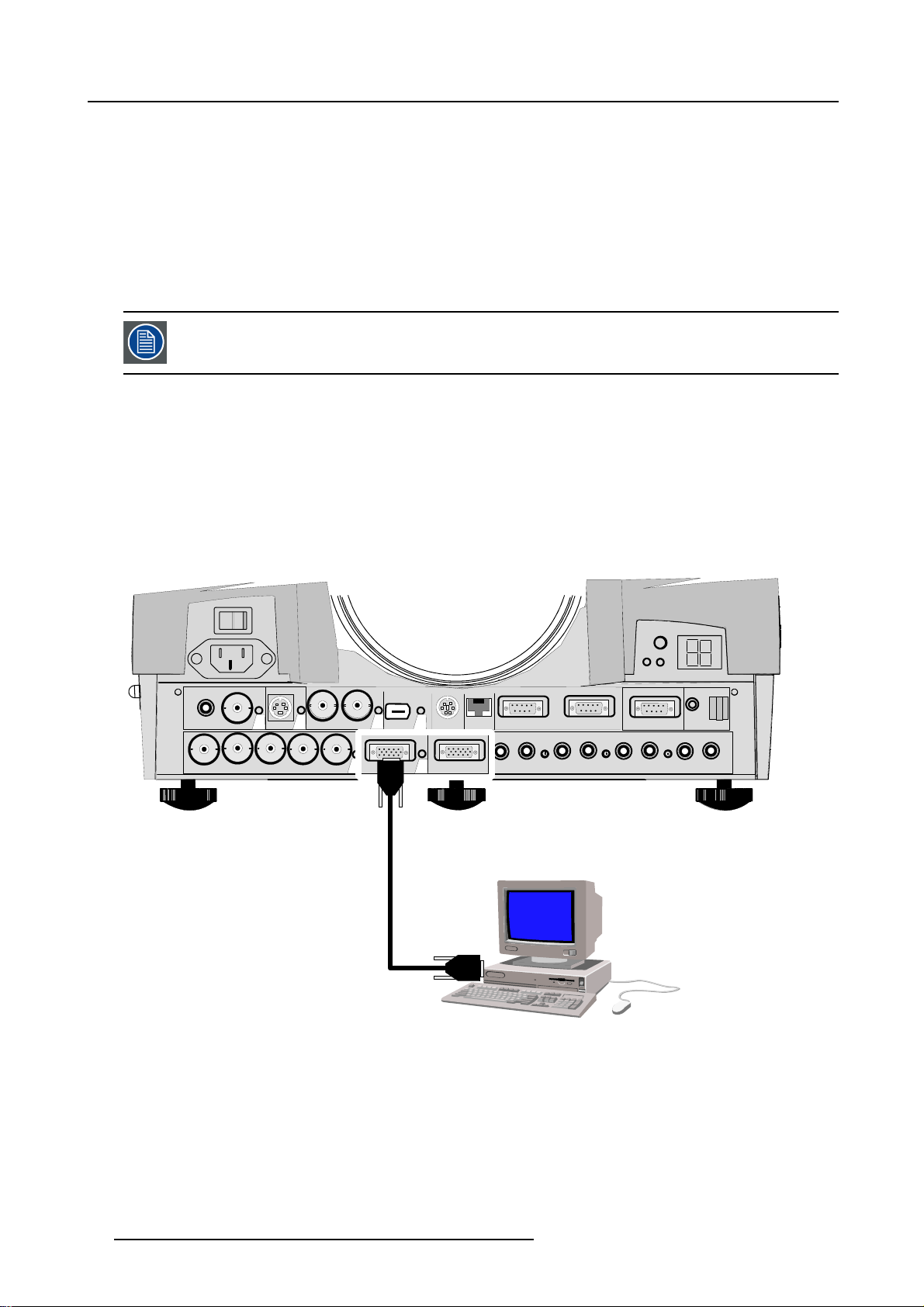
3.5.4 Computer input
How to connect a computer to the projector ?
1. Connect the output of the graphical card of the computer to the Computer input of the projector (image 3-5)
Note: Only ifthe connection is < 60 cm. Otherwise insert an interface between the output ofthe computer and the inputof the
projector.
VIDEO
GB H/C
R
S-VIDEO
SDI
5
IEEE 1394
SDO
COMPUTER
1
V
43
Image 3-5
Pin configuration of the D15 connector.
1RED
2
3BLUE
GREEN
6
MOUSE
2
MONITOR
RS232 IN
10/100 Base-T
A
AUDIO IN AUDIO IN AUDIO IN
RS232 OUT
COMM. PORT
RC
CB
AUDIO IN
4 loop through to monitor
18
R5976493 BARCOREALITY SIM 6 MK II 08092003
Page 23
3. Connections
5
ground
6 ground
7
ground
8 ground
9 loop through to monitor
10 ground
11 loop through to monitor
12 loop through to monitor
13
horizontal/composite sync
14 vertical sync
15 loop through to monitor
How to select slot 2.
1. Key in 2 on the RCU or local keypad.
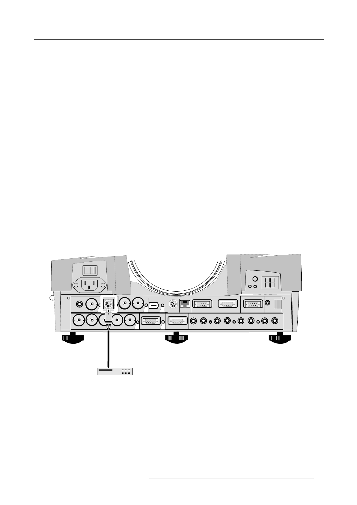
3.5.5 S-Video Input (optional)
What can be connected?
Separate Y-luma/C-chroma signals for higher quality playback of Super VHS-signals.
How to connect an S-Video Input ?
1. Connect the S-video output of your source to the S-video input of the projector (slot 4) (image 3-6)
Image 3-6
VIDEO
GB H/C
R
VCR
S-VIDEO
43
SDI
SDO
1
V
5
IEEE 1394
COMPUTER
6
MOUSE
2
MONITOR
RS232 IN
10/100 Base-T
A
AUDIO IN AUDIO IN AUDIO IN
RS232 OUT
COMM. PORT
B
C
Pin configuration of the mini DIN plug.
RC
AUDIO IN
1 ground luminance
2 ground chrominance
3 luminance 1.0Vpp ± 3dB
4 chrominance 282 mVpp ± 3dB
R5976493 BARCOREALITY SIM 6 MK II 08092003
19
Page 24
3. Connections
3.5.6 SDI input / SDI output (optional)
What can be connected ?
Full compatibility with digital Betacam, or digital video sources. This avoids the need for analog processing anywhere in the video
production chain and guarantees the ultimate image quality. An active loop through of the SDI input signal is provided for monitoring
or for double or triple stacking applications.
An active loop through of the SDI input signal is provided for monitoring or for double or triple stacking applications.
How to connect a SDI source ?
1. Connect the out of your SDI source to the BNC SDI input of the projector.
Note: The input is always 70 oh m terminated.
2. If loop through is needed, use the SDI output to connect to next device.
Note: The output impedance of the SDI output is 75 ohm.
How to select slot 5
1. Key in 5 on the RCU or the local keypad.
When a RCVDS05 is connected to the projector, the SDI input is available by keying in 85 on the RCU.
3.6 Communications connections
Overview
• RS232
3.6.1 RS232
Application
1. Remote control :
- easy adjustment of projector via an IBM PC (or compatible) or MAC connection.
- allow storage of multiple projector configurations and set ups.
- wide range of control possibilities.
- address range from 0 to 255.
2. data communications : sending data to the projector or copying the data from the projector to a hard memory device (hard disc,
floppy, etc.).
How to connect ?
1. Connect the serial communication port of computer or Apple Macintosh to the RS232 in port of the projector.
20 R5976493 BARCOREALITY SIM 6 MK II 08092003
Page 25

4. Getting started
4. GETTING STARTED
4.1 RCU & Local keypad
How controlling the projector ?
The projector can be controlled by the local keypad or by the remote control unit.
Location of the local keypad ?
The local keypad is located on the backside of the projector.
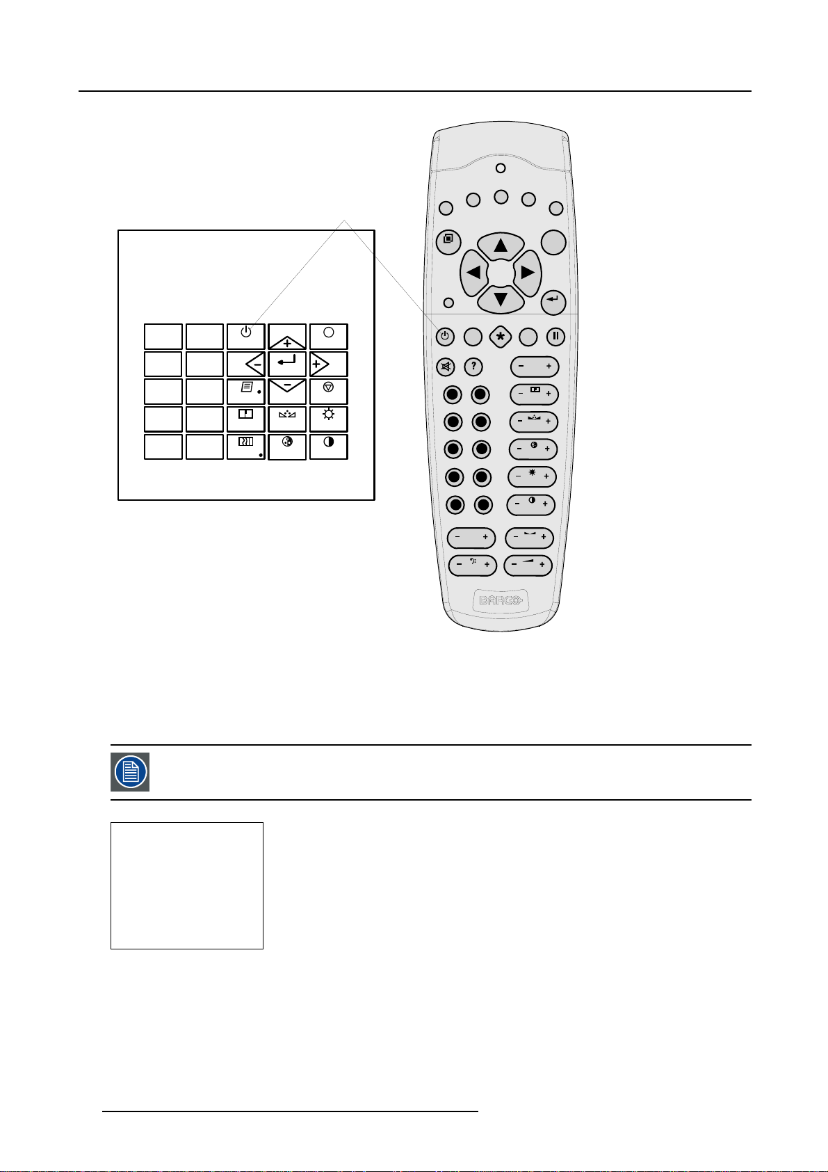
Remote control functions.
This remote control includes a battery powered infrared (IR) transmitter that allows the user to control the projector remotely. This
remote control is used for source selection, control, adaptation and set up. It includes automatic storing of picture controls (Brightness, Sharpness...) and settings.
Other functions of the remote control are :
• switching between stand by and operational mode.
• switching to "pause" (blanked picture, full power for immediate restarting)
• direct access to all connected sources.
4.2 Terminology overview
Overview
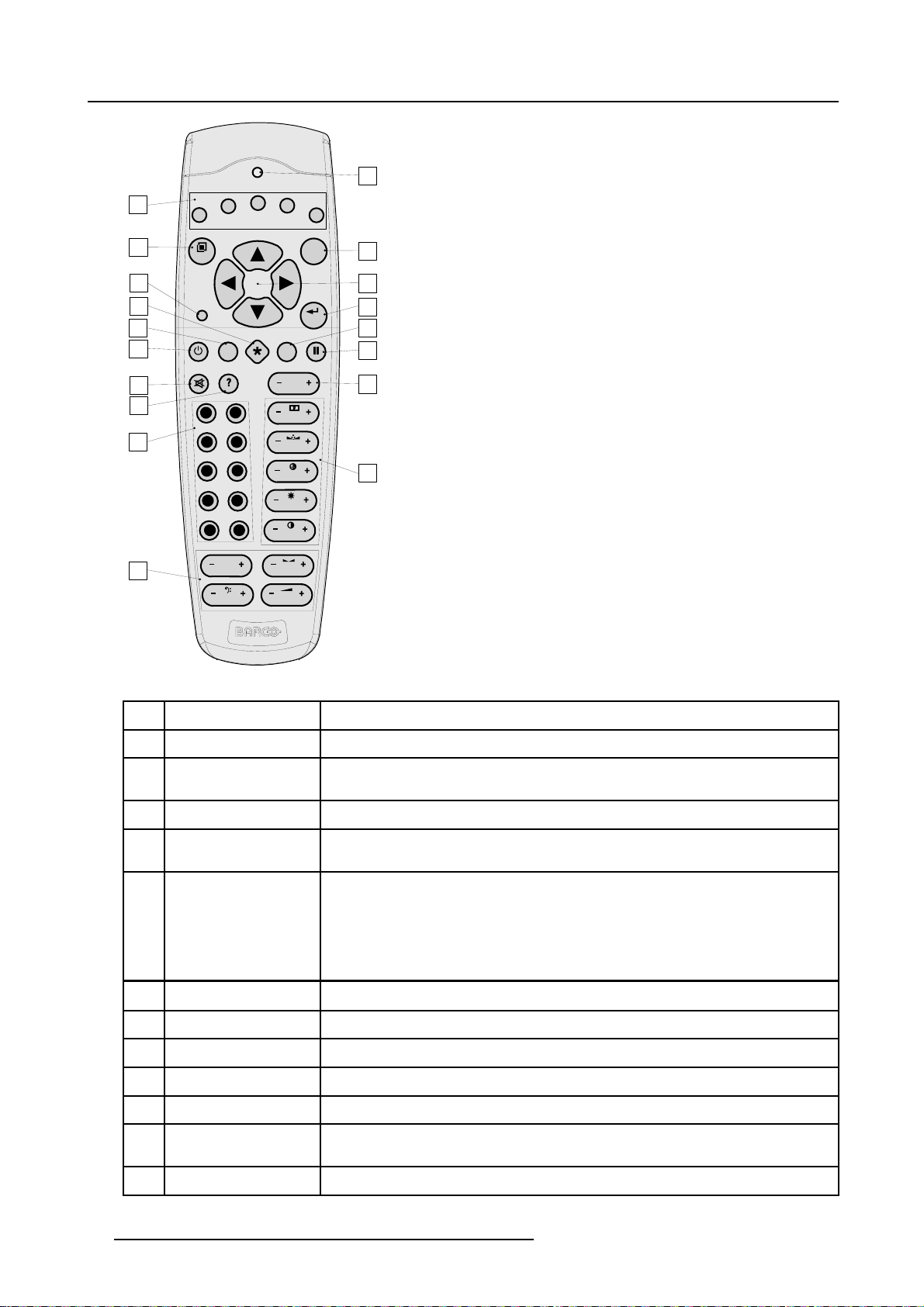
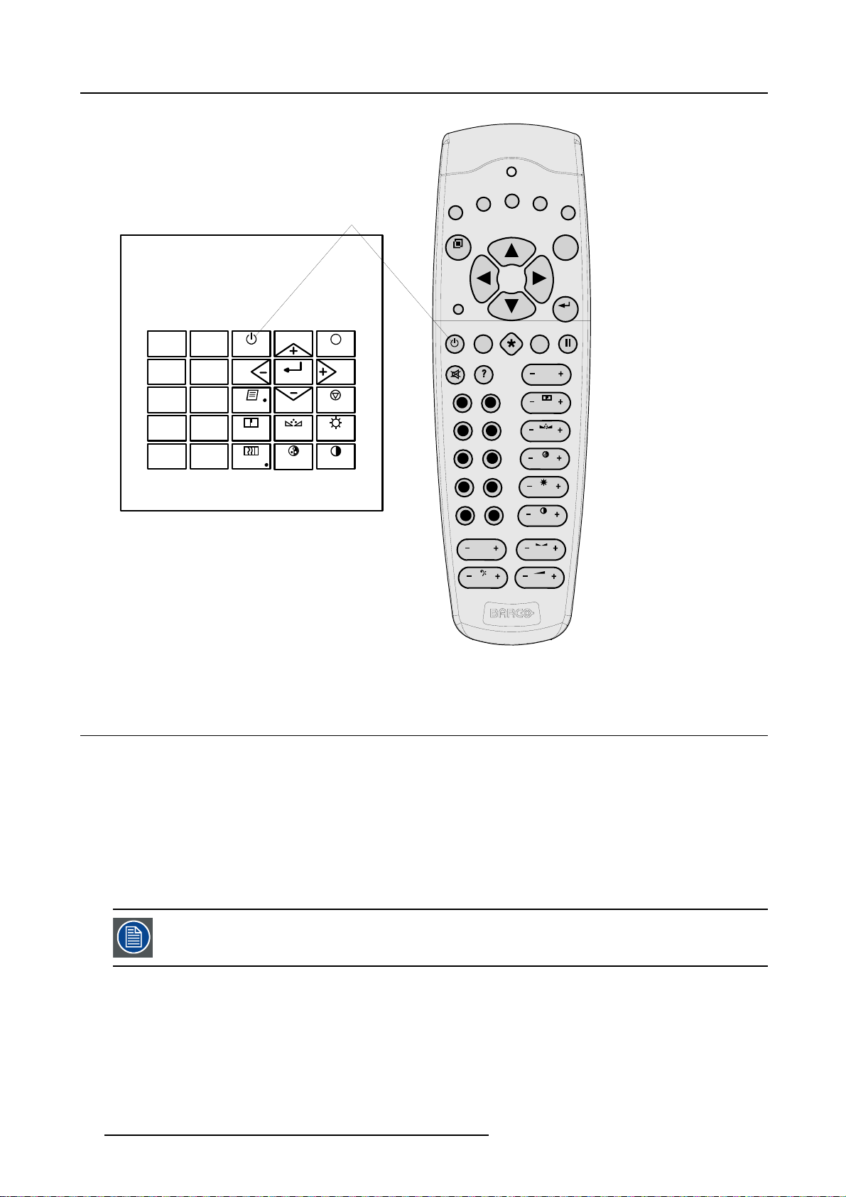
The following table gives an overview of the different functionalities o
f the keys.
R5976493 BARCOREALITY SIM 6 MK II 08092003
21
Page 26
4. Getting started
1
F1
18
F3
F2
F4
F5
2
ADJ
3
4
5
6
7
8
9
9
7
5
34
1
10
Image 4-1
RCU function indication
PAUSE
0
8
6
TREBLE BALANCE
BASS
TEXT
PHASE
SHARPN
TINT
COLOR
BRIGHTN
2
CONTR
VOL
EXIT
ENTER
17
16
15
14
13
12
11
1 Function keys
user programmable keys with functions for direct access.
2 ADJ. Adjust key, to enter the adjustment mode
3 Address key
(recessed key), to enter the address of the projector (between 0 and 9). Press the recessed
address key with a pencil, followed by pressing one digit button between 0 and 9.
4
Selection key (*) to direct access the zoom/focus/shift functions.
5
PAU SE to stop projection for a short time, press ’PAUSE’. The image disappears but full power is
retained for immediate restarting.
6
STBY standby button, to start projector when the power switch is switched on and to switch off the
projector without switching off the power switch.
Attention : Switching to Standby. When the projector is running and you want to
go to standby, press the standby key for 2 seconds until the message ’Saving data,
please wait’ is displayed. Do not press
any longer on the standby key otherwise
the projector will restart.
7
MUTE to interrupt the sound reproduction.
8
? Auto image, to center the image on the active LCD surface.
9 Digit buttons direct input selection.
10 Audio controls use these buttons to obtain the desired sound level.
11 Picture controls press to adjust the projected image.
12 Phase
be sure the projector is warmed up for at least 15 min before adjusting the phase, press to
adjust the phase of the projected image.
13 FREEZ
press to freeze the projected image.
22 R5976493 BARCOREALITY SIM 6 MK II 08092003
Page 27
4. Getting started
14 TEXT
15 ENTER
16
Cursor keys to make menu selections when in the adjustment mode or to zoom/focus when the direct
17 EXIT to leave the adjustment mode or to scroll upwards when in the adjustment mode.
18
RC operation indication lights up when a button on the remote control is pressed. (This is a visual indicator to
Table 4-1
when adjusting one of the image, e.g. controls during a meeting, the displayed bar scale
can be removed by pressing ’TEXT’ key first. To re-display the bar scale on the screen,
press ’TEXT’ key again.
to start up the adjustment mode or to confirm an adjustment or selection in the adjustment
mode.
access is active.
Comparison between the cursor keys and the use of the ’+’ and ’-’ keys on the local keypad
: RCU = local keypad
cursor key up = ’+’ key up
cursor key down = ’-’ key down
cursor key right = ’+’ key right
cursor key left = ’-’ key left
check the operation of the remote control)
4.3 Operating the projector
4.3.1 Switching on
How to switch on.
1. Press the power switch to switch on the projector.
- When ’0’ is visible, the projector is switched off.
- When ’1’ is visible, the projector is switched on
The projector starts in standby mode. The projector indication lamp is red.
Starting image projection.
1. Press Stand by key once on the local keypad or on the remote control.
The projector mode indication lamp will be green (image 4-2, image 4-3)
Projector mode indication
Image 4-2
R5976493 BARCOREALITY SIM 6 MK II 08092003 23
Page 28
4. Getting started
Stand-by key
F3
F2
F1
F4
F5
Image 4-3
ADJ
9
7
5
3
1
0
STANDBY
8
6
4
SHARPN
2
TEXT
PHASE
ENTER
COLOR
TINT
EXIT
PAUSE
BRIGHTN
CONTRAST
PAUSE
0
9
8
7
6
5
34
2
1
TREBLE BALANCE
BASS
EXIT
ENTER
TEXT
PHASE
SHARPN
TINT
COLOR
BRIGHTN
CONTR
VOL
4.4 Quick setup adjustments
Overview
• Quick lens Adjustment
• Quick on Screen Color Change.
4.4.1 Quick lens Adjustment
What can be done ?
For a quick lens adjustment press the * key on the RCU to display immediately the lens menu.
If the “Rugged” option is installed the * key will display a WARNING message.
24 R5976493 BARCOREALITY SIM 6 MK II 08092003
Page 29

WARNING
LENS-LOCKING
IS ACTIVATED
ADJUSTING THE LENS
MAY DAMAGE THE
PROJECTOR
PRESS * TO ADJUST
<EXIT> to return
Menu 4-1
Quick zoom/focus adjustment
1. Press the Selection key *.
The zoom/focus menu will be displayed.
2. Push the cursor key ↑ or ↓ to zoom and ← or → to focus the image.
3. When finished, press EXIT key to return or ENTER to continue to the shift adjustment.
Quick shift adjustment
1. Press the Selection key *
The zoom/focus menu will be displayed.
2. Press ENTER.
The shift menu will be displayed.
Or,
Push the cursor key ↑ or ↓ to shift the image up or down and ← or → to shift the image left or right.
3. When finished, press EXIT key to return or ENTER to continue to zoom/focus.
4. Getting started
4.4.2 Quick on Screen Color Change.
What can be done ?
For quick change of the on-screen color of the highlighted items.
The highlighted items on the menus can be displayed in red, green or yellow.
How to change ?
1. Press ENTER to start up the adjustment mode.
2. Push the cursor key ↑ or ↓ to highlight Installation. (menu 4-2)
3. Press ENTER to select.
4. Push the cursor key ↑ or ↓ to highlight More... (menu 4-3)
5. Press ENTER to select. (menu 4-4)
6. Push the cursor key ↑ or ↓ to highlight OSD COLOR
The OSD color menu will be displayed. (menu 4-5)
7. Push the cursor key ↑ or ↓ to highlight the desired color.
8. Press ENTER to activate.
ADJUSTMENT MODE
Select a path from below :
RANDOM ACCESS
INSTALLATION
SERVICE
Select with ↑ or ↓
then <ENTER>
<EXIT> to return
INSTALLATION
INPUT SLOTS
NO SIGNAL
LENS
MENU POSITION
QUICK ACCESS KEYS
800 PERIPHERAL
MORE ...
Select with ↑ or ↓
then <ENTER>
<EXIT> to return
INSTALLATION
CONFIGURATION
OSD COLOR
INTERNAL PATTERNS
SHUTTER
ACTIVE 3D CONF.
MORE ...
Select with ↑ or ↓
then <ENTER>
<EXIT> to return
OSD COLOR
HIGHTLIGHTED ITEM
RED
GREEN
YELLOW
Select with ↑ or ↓
then <ENTER>
<EXIT> to return
Menu 4-2
Menu 4-3
Menu 4-4
Menu 4-5
R5976493 BARCOREALITY SIM 6 MK II 08092003 25
Page 30
4. Getting started
4.5 Using the RCU
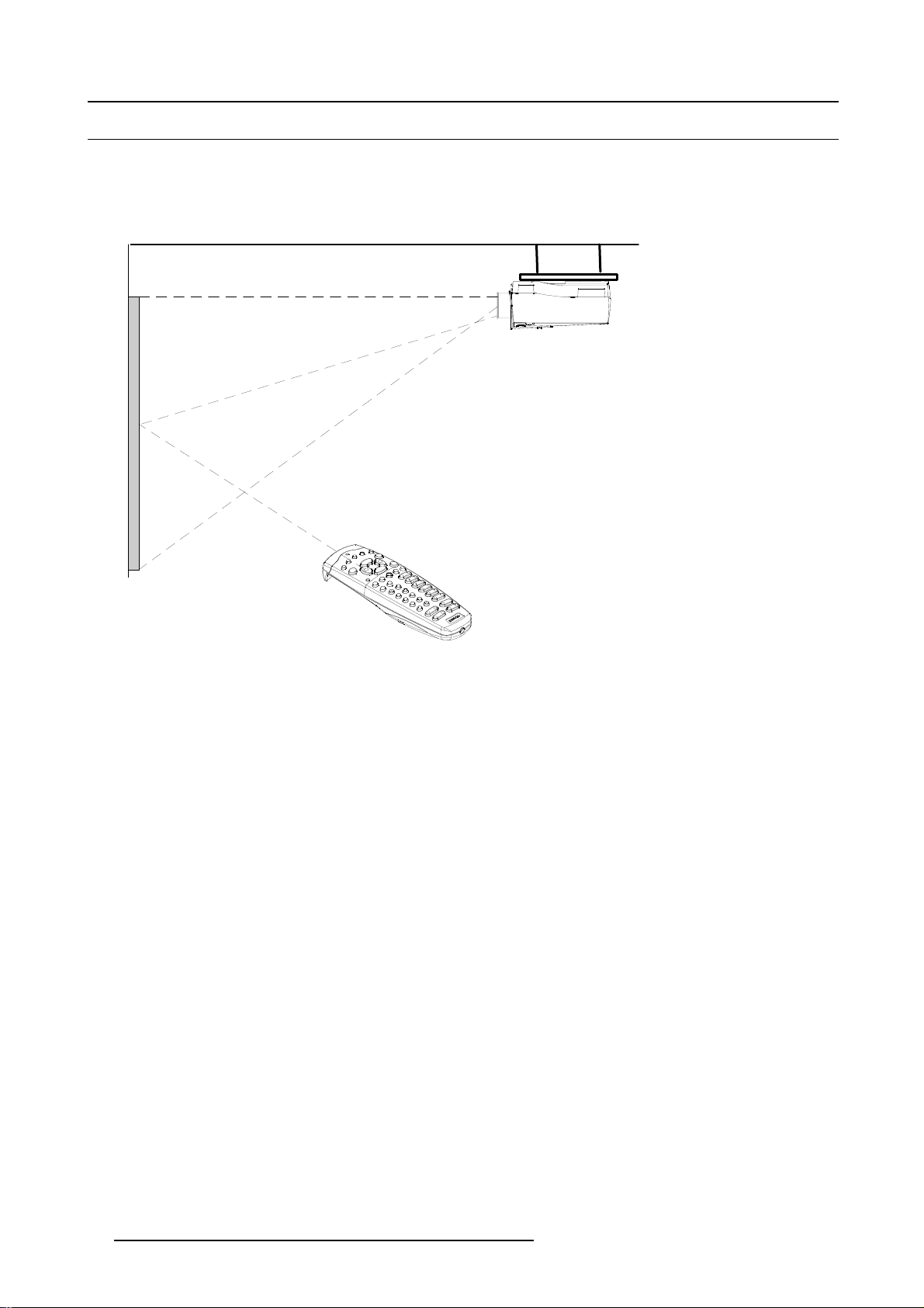
Pointing to the reflective screen
1. Point the front of the RCU to the reflective screen surface. (image 4-4)
Ceiling
Screen
IR sensor
RCU
Image 4-4
Pointing the RCU via the screen to the IR sensor
Hardwired Remote Input
1. Plug one end of the remote cable in the connector on the bottom of the RCU.
2. Plug the other end in the connector in the front panel of the projector labelled RC. (image 4-5)
26 R5976493 BARCOREALITY SIM 6 MK II 08092003
Page 31

4. Getting started
VIDEO
GB H/C
R
Image 4-5
RCU Hardwired to Remote Input
S-VIDEO
43
SDI
SDO
1
V
5
IEEE 1394
COMPUTER
6
MOUSE
2
MONITOR
RS232 IN
10/100 Base-T
A
AUDIO IN AUDIO IN AUDIO IN
RS232 OUT
COMM. PORT
RC
CB
AUDIO IN
Directly to one of the IR sensors of the projector.
When using the wireless remote control, make sure you are within the effective operating distance (30m, 100ft in a straight line). The
remote control unit will not function properly if strong light strikes the sensor window or if there are obstacles between the remote
control unit and the projector IR sensor.
R5976493 BARCOREALITY SIM 6 MK II 08092003
27
Page 32

4. Getting started
43
S-VIDEO
SDI
VIDEO
SDO
1
V
RGBH/C
RS232 IN RS232 OUT
AUDIO IN AUDIO IN AUDIO IN
A
COMM. PORT
CB
AUDIO IN
6
TRIG
MOUSE
5
IEEE 1394
2
MONITOR
COMPUTER
RC
45ø
F2F3F4
F1
ADJ EXIT
PAUSE
90
78
6
5
34
2
1
TREBLE BALANCE
BASS
Image 4-6
RCU directly to the IR sensor
4.6 Projector Address
4.6.1 Controlling the projector
Projector address
Address installed in the projector to be individually controlled.
45ø
F5
ENTER
TEXT
PHASE
SHARPN
TINT
COLOR
BRIGHTN
CONTR
VOL
45ø 45ø
F3
F2
F4
F5
F1
ADJ
EXIT
ENTER
PAUSE
TEXT
PHASE
90
SHARPN
8
7
TINT
6
5
COLOR
34
BRIGHTN
2
1
CONTR
TREBLE BALANCE
BASS VOL
Common address
Default address. Projector will always execute the command coming from a RCU programmed with that common
address.
Why a projector address ?
As more than one projector can be insta
computer. There for each projector has its own address.
lled in a room, the separate projector should be separately addressable with an RCU or
Set up an individual Projector Address.
The set up of a projector address can be done via the software. See ’Change projector address’ in chapter ’Service mode’.
Projector controlling.
Every projector requires an individual address between 0 and 255 which can be set in the Service mode.
Whentheaddressisset,theprojectorcanbecontrollednow:
• RCU for addresses between 0 and 9.
• computer, e.g. IBM PC (or compatible), Apple MAC, etc. for addresses between 0 and 255.
28
R5976493 BARCOREALITY SIM 6 MK II 08092003
Page 33

A projector will respond to a RCU set to the common address (’0’ or ’1’) regardless of what address is set in
the projector itself.
The RCU is default programmed with address 0 or 1, ’common address’. With that ’common address’ programmed into the RCU, every projector, without exception will listen to the commands given by this RCU. If
it is necessary to control a specific projector, than enter the projector address into the RCU (only when that
address is between 0 and 9). The projector with the corresponding address will listen to that specific RCU.
Common Address
Every projector has a common address ’0’ or ’1’. The choice between ’0’ and ’1’ can be selected in the Service mode.
4.6.2 Displaying and Programming addresses
Displaying the Projector Address on the Screen.
1. Press Address key (recessed key on the RCU) with a pencil.
The projector’s address will be displayed in a ’Text box’
To continue using the RCU with that specific address, it is necessary to enter the same address with the
digit buttons (address between 0 and 9) within 5 seconds after pushing the address key. For example : if the
Address key displays projector address 003, then press "3" digit button on the RCU to set the RCU’s address
to match the projector’s address. Do not press 003 digits. This will address the remote control to ’0’ and
control all projectors in the room. If the address is not entered within 5 seconds, the RCU returns to its default
address (zero address) and control all projectors in the room.
4. Getting started
How to Program an Address into the RCU?
1. Press the Address key (recessed key on the RCU) with a pencil.
2. Enter the address with the digit buttons within 5 seconds after pushing the address key.
Note: That address can be any digit between 0 and 9.
4.7 Controlling the projector
Input Selection
Key in the corresponding slot number with the digit keys on the RCU. The selected source will be displayed.
Picture Controls
When an image control is pressed, a text box with a bar scale, icon and function name of the control, e.g. ’brightness...’ appears on
the screen (only if text is ON). See example screen. T
current memorized setting for this source. The bar scale changes as the control stick on the RCU is pressed or the + or - buttons
on the local keypad.
Brightness
Contrast A correct ’contrast’ setting is important for go
A correct ’brightness’ setting is important for good image reproduction.
Use the + button for a higher brightness.
Use the - button for a lower brightness.
you prefer, according to room lighting conditions.
Use the + button for a higher contrast.
Use the - button for lower contrast.
he length of the bar scale and the value of the numeric indication indicate the
od image reproduction. Adjust the contrast to the level
Color Color saturation is only active for Video and
Use the + button for richer colors.
Use the - button for lighter colors.
R5976493 BARCOREALITY SIM 6 MK II 08092003 29
S-Video. Adjust the color intensity of the picture.
Page 34

4. Getting started
Tint
Sharpness Use the + button for a sharper picture.
Phase Use the + or - button to adjust the phase.
Freez
Tint is only active for Video and S-Video when using the NTSC 4.43 or NTSC 3.58 system.
Use the + button
Use the - button.
Use the - button for a softer picture.
Press Freez to freeze the displayed image.
Sound Controls
When a sound control is pressed, a text box with a bar scale, icon and function name of the control, e.g. ’volume...’ appears on the
screen (only if text is ON). See example screen. The length of the bar scale indicates the current memorized setting for this source.
The bar scale changes as the + or - buttons of the
Volume Volume control adjusts the volume.
Use the + button for a higher volume.
Use the - button for a lower volume.
Bass
Treble
Bass control adjusts the bass level (low tone
Use the + button for more low tones.
Use the - button for less low tones.
Treble control adjusts the treble level (high tones).
Use the + button for more high tones.
Use the - button for less high tones.
control are pressed. The sound controls can only be adjusted with the RCU.
s).
Balance
Is only effective if a external amplifier with loudspeakers is connected to the audio output. The balance
control adjust the sound level between the left and the right box.
Use the + button for a higher sound level on the right box than on the left one.
Use the - button for a higher sound level on the l
eft box than on the right one.
The Pause Key
When the Pause key is pressed, the image projection is stopped, a blue or black screen will be displayed and the projector remains
with full power for immediate restart. The sound is not interrupted. The display on front of the projector will show a "P".
To restart the image :
•PressPause key.
•PressEXIT key
• Select a source number.
The Selection key
See Quick lens Adjustment, page 24
30
R5976493 BARCOREALITY SIM 6 MK II 08092003
Page 35

5. RANDOM ACCESS
Overview
• Random Access Overview
• Random Access Start up
• File Services
• Picture tuning
• Audio tuning (Optional)
• Geometry
•SoftEdge
•Demo
5.1 Random Access Overview
Random Access Overview
• File Service
- Load
-Edit
- Rename
- Copy
-Delete
- Options
o
File Sort [Name/Index]
o
File Load [Automatic/Manual]
o
Serial File Load [On/Off]
• Picture Tuning
- CTI [On/Off] (Optional)
- Motion Compensation (Optional)
o
LCD Speed
o
LCD Speed R/G
o
LCD Speed B/G
- Color Temperature
o
Projector White
o
Computer 9300K
o
Video 6500K
o
Film 5400K
o
Broadcast 3200K
o
Custom Balance
- Gamma
- Decoding [EBU/IRE] (Optional)
- Color Depth
- Input Balance
o
White Balance
o
Black Balance
o
Default
- Black Color
• Audio Tuning (Optional)
- Volume
-Balance
-Bass
- Treble
-Mute[On/Off]
- Fade
- Mode [Mono/Stereo]
- Video-Audio Lock
5. Random Access
R5976493 BARCOREALITY SIM 6 MK II 08092003
31
Page 36

5. Random Access
• Geometry
-Shift
-Size
- Side Keystone
- Blanking
o
To p
o
Bottom
o
Left
o
Right
- Aspect Ratio
- Options [Yes/No]
• Soft Edge
- Type
o
None
o
Left
o
Right
o
Left+Right
o
To p
o
Bottom
o
Top+Bottom
-Size
- Options [Yes/No]
•Demo
- Split Screen [On/Off]
5.2 Random Access Start up
How to start up ?
1. Push the cursor key ↑ or ↓ to highlight Random Access. (menu 5-1)
2. Press ENTER.
ADJUSTMENT MODE
Select a path from below :
RANDOM ACCESS
INSTALLATION
SERVICE
Select with ↑ or ↓
then <ENTER>
<EXIT> to return
Menu 5-1
5.3 File Services
5.3.1 File annotation
How a file is built up
The file notation on a menu is built up in different parts. Let us have a look to these parts.
Take the following notation : xxxxxxxx.eee n ppppXppppi
32
R5976493 BARCOREALITY SIM 6 MK II 08092003
Page 37

5. Random Access
xxxxxxxx
eee
base name, 8 characters
file extension
first character C : custom made file
first character S : standard file
The second and third character is used for a following number (= file
index). The file index for custom files : 01 to 20.
n
source number
ppppXpppp active pixel rating
i i or blank
i = interlaced file
blank = not interlaced
Table 5-1
5.3.2 Possible file manipulations
Connecting a new source.
Before using a new source, a correct file has to be installed. The projector’s memory contains a list of files corresponding to the most
used sources. When the new source corresponds with one of these files, the file can be loaded and saved for future use. When
there is a little difference, the file can also be loaded and then edited until the source specs are reached.
File loading can be done automatically. Files with a ~ in front of the file name are temporary files. These files
will be deleted when switching to another source.
Possible file Manipulations
The following file manipulations are possible :
• Load : installation of a file for a new
• Edit : editing a loaded file to the source specs.
• Rename : renaming a file.
• Copy : copying a file.
• Delete : deleting a file
• Options : way of sorting the files.
5.3.3 Start up of the file services
Start up
To enter the File Service, handle as follow :
1. Push the cursor key ↑ or ↓ to highlight
2. Press ENTER to select.
The File Service menu will be displayed.
RANDOM ACCESS
ADJUSTMENT MODE
FILE SERVICE
PICTURE TUNING
AUDIO TUNING
GEOMETRY
SOFT EDGE
DEMO
Select with ↑ or ↓
then <ENTER>
<EXIT> to return
source.
File Service. (menu 5-2)
Menu 5-2
R5976493 BARCOREALITY SIM 6 MK II 08092003 33
Page 38

5. Random Access
5.3.4 Load file
StartupLoadfile
To start up the load file, handle as follow :
1. Push the cursor key ↑ or ↓ to highlight Load. (menu 5-3)
2. Press ENTER to select.
The Load menu displays the corresponding files depending on the installed filter. (menu 5-4)
Menu 5-3
FILE SERVICE
LOAD
EDIT
RENAME
COPY
DELETE
OPTIONS
Select with ↑ or ↓
then <ENTER>
<EXIT> to return
F
video525.s01 1 675x240i
video525.c01 1 675x240i
video525.c02 1 675x240i
----------------------------
Active file : Video525.c50
Menu 5-4
LOAD FILE
FILTER LIST [All]
ilename Src resolution
Select with ↑ or ↓ , →
<ENTER> to accept
<EXIT> to return
Changing the filter setting
1. Push the cursor key ↑ or ↓ highlight filter list.
2. Press ENTER to toggle the annotation between brackets.
[All] : all files that can be loaded will be displayed.
[Fit] : only the best fitting files will be displayed (with a distinction of ± 2 lines and line dur
ation of ± 300 ns, if nothing is found
within this small area, the projector continues searching until it finds something).
Howtoloadafile?
1. Push the cursor key ↑ or ↓ to select the best fitting file. (menu 5-5)
2. Press ENTER to select.
A confirm Load file menu will be displayed with the newly created file and the one on which the new file is based on. (menu 5-6)
3. Press ENTER to confirm the new creation or EXIT to return to the load file menu.
LOAD FILE
FILTER LIST [All]
ilename Src resolution
F
video525.s01 1 675x240i
video525.c01 1 675x240i
video525.c02 1 675x240i
---------------------------Active file : Video525.c50
Select with ↑ or ↓ , →
<ENTER> to accept
<EXIT> to return
Menu 5-5
Menu 5-6
CONFIRM
LOAD FILE
create file
Video525.c02
based on file
Video525.s01?
<ENTER> to return
<EXIT> to return
During a load file, the actual file is displayed next to the indication Active file.
When scrolling through the files, the image will be adapted according to the settings of the selected file ( on
line adaptation.
The image is not perfect ?
If the displayed image is not correct after selecting the best fitting file, go to the Edit menu, select the active file and change the File
settings.
34
R5976493 BARCOREALITY SIM 6 MK II 08092003
Page 39

5. Random Access
5.3.5 Edit file
The Edit file menu makes it possible to change the settings of the file according to the real settings of the connected source. Consult
the source specification before entering the data.
•Startup
• Changing the settings
• Correct value
• Rename
• Copy
• Delete
• File options
5.3.5.1 Start up
How to start up the Edit menu ?
To start up the EDIT menu :
1. Push the cursor key ↑ or ↓ to highlight Edit. (menu 5-7)
2. Press ENTER to select.
The Edit file adaptation menu will be displayed. (menu 5-8)
3. Select the file which must be edited (mostly the active file).
4. Press ENTER.
The file name will be displayed in the upper right corner. (menu 5-9)
Menu 5-7
FILE SERVICE
LOAD
EDIT
RENAME
COPY
DELETE
OPTIONS
Select with ↑ or ↓
then <ENTER>
<EXIT> to return
F
video525.s01 1 675x240i
video525.c01 1 675x240i
video525.c02 1 675x240i
------------------------------Active file : Video525.c50
Menu 5-8
EDIT FILE
ilename Src resolution
Select with ↑ or ↓ , →
<ENTER> to accept
<EXIT> to return
EDIT FILE xga.s30
HORIZONTAL
TOTAL 1344 PIXELS
ACTIVE 1024 PIXELS
START 296 PIXELS
PERIOD 20.678 µs
VERTICAL (FIELD)
TOTAL 806 LINES
ACTIVE 768 LINES
START 36 LINES
INTERLACED [OFF]
READ AMDS
OPTIONS
↑ , ↓ , ← , → <ENTER>, <EXIT>
Menu 5-9
5.3.5.2 Changing the settings
Different methods
The 3 different methods to change a setting will be describe hereafter. These methods are:
• with the numeric keys on the remote control.
• with the arrow keys selecting the changing digit.
• with the arrow keys counting up or down.
How to change a setting with the numeric keys?
1. Push the cursor key ↑ or ↓ to highlight an item.
The color of the selected item will change.
2. Press ENTER to activate the digits.
3. Enter directly with the numeric keys on the RCU or local keypad the new value.
How to change a setting with the cursor keys?
1. Push the cursor key ↑ or ↓ to highlight an item.
The color of the selected item will change.
2. Press ENTER to activate the digits.
3. Push the cursor key ← or → to select the changing digit.
4. Push the cursor key ↑ or ↓ to scroll to the desired digit.
5. When finished, press ENTER to confirm.
R5976493 BARCOREALITY SIM 6 MK II 08092003
35
Page 40

5. Random Access
How to change a setting with the cursor keys and counting up or down?
1. Push the cursor key ↑ or ↓ to highlight an item.
The color of the selected item will change.
2. Press ENTER to activate.
3. Counting up or down by pushing the cursor key ← or →.
5.3.5.3 Correct value
What is already available during start up?
During the installation of a file with LOAD, the horizontal period, the total number of vertical lines and the interlaced mode are
automatically measured and filled in, in the menu table. These values will be available when starting up the EDIT procedure of an
active file.
Do not adjust these settings on an active file, they are used to identify the input source file.
How to find the correct values for the item in the Edit file menu?
Horizontal Total Pixels
If the value for "Horizontal Total Pixels" is wrong, sampling mistakes (small vertical bars with noisy
and unsharp data in the projected image) will be seen in the image.
Select "Total" and adjust the pixel quantity. Adjust for zero bars.
hint: if the number of bars increase, adjust in the other direction.
Active Pixels
The "Active Pixels" : determine the width of the window on the screen. This value is normally given in
the source specifications. If not, adjust until full image is displayed (no missing pixels).
Horizontal Start number of pixels between the beginning of the input signal and the start of the video information in
the signal.
Horizontal Period
Vertical Total Lines
Active Lines
already filled in with the correct value when active file.
already filled when an active file is selected to be edited
number of horizontal lines determining the height of the projected image. This value is normally given
in the specification of the source. If not, adjust until full image height is displayed (no missing lines)
Vertical Start number of lines between the start of the input signal and start of the image on the screen.
Interlaced [On] or [Off] this selection is automatically filled when active file has to be edited. If the image is wrong due to
mismeasurement, use the ENTER key to toggle between [On] and [Off]. (for interlaced images,
1 frame contains 2 fields).
Read AMDS AMDS = automatic mode detection & synchronization
During the installation of a file with LOAD, the system automatically measured the horizontal period,
the total vertical lines and the interlaced mode. When selecting Read AMDS, the system remeasures
the above indicated items.
How to install the correct settings for the options in the Edit file menu.
EDIT FILE OPTIONS
Source number 1
Clamp position [leading]
Clamp delay 0
Clamp width 10
Field polarity [pos]
Field select [both
Vertical refresh [sync]
Vertical sync polarity [leading]
Select with ↑ or ↓
<ENTER> to toggle
↑ or ↓ to change value
<EXIT> to return
Menu 5-10
36 R5976493 BARCOREALITY SIM 6 MK II 08092003
]
Page 41

5. Random Access
Source number The source number of a non-active source can be changed to any other source number. This makes
itpossibletocreateafileforfuturesourcenumbers.
Clamp position Clamping determines the black level of the signal. The clamp pulse can be related to the leading or
the trailing edge of the sync pulse. Use the ENTER key to toggle between [leading] and [trailing].
Clamp delay The time between the leading edge of the clamp pulse and the locked edge of the sync pulse. Can be
any value between 0 and 255. Change the value by pushing the cursor key ↑ or ↓.
Clamp width The width of the clamp pulse can be any value between 0 and 255. Change the value by pushing
the cursor key ↑ or ↓.
Leading edge
Trailinging edge
Sync
pulse
Clamp
pulse
Clamp
Clamp
delay
width
Image 5-1
Example for Clamp position [trailing]
Field polarity
Field select
Vertical refresh
[sync/async]
Vertical Sync Polarity:
[leading] or [trailing]
The field polarity function is used for interlaced images. Both rasters of the image could be shifted in a
wrong way (double lines are visible in the image). This can be corrected by forcing the field polarity to
[neg] or [pos]. Use the ENTER key to toggle between [pos] and [neg].
Default [both]
The field select is only used for interlaced images. One frame of an i
nterlaced image contains two
fields, an even and an odd field. The choice exists to project [both] fields on the screen or only the
[even] or [odd] field.
Use the ENTER key to toggle between [both], [even] and [odd].
If the active Stereo Compatibility Option is installed, t
he field select parameter will be changed
into a [left] and [right] selecting parameter which will be selectable for stereo files. This setting
will then be saved in the active image file.
The way of updating the image information on the LCD panels. Not available for PAL-NTSC-SECAM
sources. Where this option will be displayed in gray.
• For sources with a vertical frequency up to 60 Hz : the vertical refresh rate is the same as the
vertical frequency of the incoming source. This is a necessity to project moving images without
’motion artifacts’. For stationary image
s with a vertical frequency up to 60 Hz it is still possible to
use asynchronous refresh.
• For sources with a vertical frequency higher than 60 Hz : the vertical refresh is different than the
vertical frequency of the incoming source. Synchronous refresh cannot be used.
The vertical refresh can be synchronized with the leading sync edge or trailing sync edge. Default on
[leading]. Toggling to [trailing] is only necessary for special applications where the trailing edge of the
sync signal has to be taken as a reference. Use the ENTER key to toggle between [leading] or [trailing]
R5976493 BARCOREALITY SIM 6 MK II 08092003 37
Page 42

5. Random Access
5.3.5.4 Rename
Start Up
To change the name of a selected file :
1. Push the cursor key ↑ or ↓ to highlight Rename. (menu 5-11)
2. Press ENTER.
The Rename selection menu will be displayed. (menu 5-12)
3. Push the cursor key ↑ or ↓ to select a file name.
4. Press ENTER to select.
The Rename file menu will be displayed with the selected file name already filled in, in the ’From file name :’ area and in the ’To
file name :’ area. The first character in the ’To file name :’ area is highlighted. (menu 5-13)
Menu 5-11
FILE SERVICE
LOAD
EDIT
RENAME
COPY
DELETE
OPTIONS
Select with ↑ or ↓
then <ENTER>
<EXIT> to return
Menu 5-12
RENAME FILE
F
ilename Src resolution
video525.s01 1 675x240i
video525.c01 1 675x240i
video525.c02 1 675x240i
------------------------------Active file : Video525.c50
Select with ↑ or ↓ , →
<ENTER> to accept
<EXIT> to return
From file name :
Video525.c01
To file name :
Select with ← or →
Reprogram with ↑ or ↓
or numeric keys
<ENTER> to confirm
<EXIT> to return
Menu 5-13
RENAME FILE
demo.c10
Changing the characters
1. Push the cursor keys ← or → to select the desired character. (menu 5-14)
Or,
Change that character by pushing the cursor keys ↑ or ↓. Numeric characters can be ent
RCU.
Or,
Press ENTER to confirm.
The renamed file is entered in the list of files.
2. Press EXIT to return to the Rename menu selection.
No changes are made.
RENAME FILE
From file name :
Video525.c01
To file name :
demo.c10
ered directly with numeric keys on the
Select with ← or →
Reprogram with ↑ or ↓
or numeric keys
<ENTER> to confirm
<EXIT> to return
Menu 5-14
38 R5976493 BARCOREALITY SIM 6 MK II 08092003
Page 43

5.3.5.5 Copy
Start Up
To copy the name of a selected file :
1. Push the cursor key ↑ or ↓ to highlight Copy.
2. Press ENTER.
The Copy selection menu will be displayed. (menu 5-15)
3. Push the cursor key ↑ or ↓ to select a file name.
4. Press ENTER to select.
The Copy file menu will be displayed with the selected file name already filled in, in the ’From file name :’ area and in the ’To file
name :’ area. The first character in the ’To file name :’ area is highlighted. (menu 5-16)
5. Random Access
COPY FILE
F
ilename Src resolution
video525.s01 1 675x240i
video525.c01 1 675x240i
video525.c02 1 675x240i
------------------------------Active file : Video525.c50
Select with ↑ or ↓ , →
<ENTER> to accept
<EXIT> to return
Menu 5-15
Menu 5-16
COPY FILE
Frome file name :
Video525.s01
To file name :
demo.c10
Select with ← or →
Reprogram with ↑ or ↓
or numeric keys
<ENTER> to confirm
<EXIT> to return
Changing the characters
1. Push the cursor keys ← or → to select the desired character. (menu 5-17)
Or,
Change that character by pushing the cursor keys ↑ or ↓. Numeric characters can be ent
RCU.
Or,
Press ENTER to confirm.
The copy file is entered in the list of files.
2. Press EXIT to return to the Copy menu selection.
No changes are made.
COPY FILE
Frome file name :
Video525.s01
To file name :
demo.c10
ered directly with numeric keys on the
Select with ← or →
Reprogram with ↑ or ↓
or numeric keys
<ENTER> to confirm
<EXIT> to return
Menu 5-17
5.3.5.6 Delete
Start up and delete
To delete a selected file out of the list of files :
1. Push the cursor key ↑ or ↓ to highlight Delete. (menu 5-18)
2. Press ENTER.
The delete selection menu will be displayed. (menu 5-19)
3. Push the cursor key ↑ or ↓ to select a file name.
R5976493 BARCOREALITY SIM 6 MK II 08092003
39
Page 44

5. Random Access
4. Press ENTER to select.
If [all] is selected, your password has to be entered before all files will be deleted.
A confirmation menu "Delete file ’file name’?" is displayed. (menu 5-20)
5. Press ENTER to delete the file, press EXIT if you want to keep it.
Note: The active file cannot be deleted.
Menu 5-18
FILE SERVICE
LOAD
EDIT
RENAME
COPY
DELETE
OPTIONS
Select with ↑ or ↓
then <ENTER>
<EXIT> to return
Menu 5-19
DELETE FILE
ilename Src resolution
F
video525.s01 1 675x240i
video525.c01 1 675x240i
video525.c02 1 675x240i
------------------------------Active file : Video525.c50
Select with ↑ or ↓ , →
<ENTER> to accept
<EXIT> to return
5.3.5.7 File options
Start up
1. Push the cursor key ↑ or ↓ to highlight Options. (menu 5-21)
2. Press ENTER to select.
The option selection menu will be displayed. (menu 5-22)
FILE SERVICE
LOAD
EDIT
RENAME
COPY
DELETE
OPTIONS
Select with ↑ or ↓
then <ENTER>
<EXIT> to return
FILE OPTIONS
FILE SORT [NAME]
FILE LOAD [AUTOMATIC]
SERIAL FILE LOAD [OFF]
Select with ↑ or ↓
then <ENTER>
<EXIT> to return
Menu 5-20
CONFIRM
DELETE FILE
Delete file :
Video525.c01?
<ENTER> to confirm
<EXIT> to return
Menu 5-21
Menu 5-22
File Sort
1. Push the cursor key ↑ or ↓ to highlight File Sort. (menu 5-23)
2. Press ENTER to toggle between [NAME] or [INDEX].
This File Sort setting is default set to [NAME].
[NAME]
[INDEX]
FILE OPTIONS
FILE SORT [NAME]
FILE LOAD [AUTOMATIC]
SERIAL FILE LOAD [OFF]
Select with ↑ or ↓
then <ENTER>
<EXIT> to return
Menu 5-23
Thefilesinthelistwillbesortedonthefilename.
The files in the list will be sorted on the file extension.
40 R5976493 BARCOREALITY SIM 6 MK II 08092003
Page 45

File Load
1. Push the cursor key ↑ or ↓ to highlight File Load. (menu 5-24)
2. Press ENTER to toggle between [AUTOMATIC] or [MANUAL].
This File Load setting is default set to [AUTOMATIC].
[AUTOMATIC] The projector will automatically load the file that is best suited for the selected Input Slot.
5. Random Access
[MANUAL]
FILE OPTIONS
FILE SORT [NAME]
FILE LOAD [AUTOMATIC]
SERIAL FILE LOAD [OFF]
Select with ↑ or ↓
then <ENTER>
<EXIT> to return
Menu 5-24
The user will select and load the desired file.
Serial File Load
1. Push the cursor key ↑ or ↓ to highlight Serial File Load. (menu 5-25)
2. Press ENTER to toggle between [OFF] or [ON].
This Serial File Load setting is default set to [OFF].
[OFF] The Serial File Load command is set to off.
[ON] The projector is forced to load a file through RS232, all other means to load a file are disabled until Serial File
FILE LOAD [AUTOMATIC]
SERIAL FILE LOAD [OFF]
Load is set to off.
FILE OPTIONS
FILE SORT [NAME]
Select with ↑ or ↓
then <ENTER>
<EXIT> to return
Menu 5-25
R5976493 BARCOREALITY SIM 6 MK II 08092003 41
Page 46

5. Random Access
5.4 Picture tuning
5.4.1 Start up
Start up
To improve the image quality, the items in the Picture Tuning menu can be toggled or adjusted. To start up the Picture Tuning :
1. Push the cursor key ↑ or ↓ to highlight Picture Tuning. (menu 5-26)
2. Press ENTER to select.
The picture tuning menu will be displayed. (menu 5-27)
Menu 5-26
RANDOM ACCESS
ADJUSTMENT MODE
FILE SERVICE
PICTURE TUNING
AUDIO TUNING
GEOMETRY
SOFT EDGE
DEMO
Select with ↑ or ↓
then <ENTER>
<EXIT> to return
Menu 5-27
PICTURE TUNING
CTI[ON]
MOTION COMPENSATION
COLOR TEMPERATURE
GAMMA
DECODING[EBU]
COLOR DEPTH
INPUT BALANCE
BLACK COLOR
Select with ↑ or ↓
then <ENTER>
<EXIT> to return
Which items are available ?
• CTI : optional
• Motion compensation: optional
• Color temperature
• Gamma
• Decoding: optional
• Color depth
• Input balance
• Black color
5.4.2 Motion Compensation (TMR) (Optional)
The Motion Compensation menu item will be greyed out when this option is not installed.
Overview
• Starting up Motion Compensation
• LCD speed
•LCDspeedR/G
•LCDspeedB/G
What can be done ?
Motion Compensation allows to change the response time of the LCD
The following options can be adjusted:
• LCD speed
•LCDspeedR/G
•LCDspeedB/G
42
panels.
R5976493 BARCOREALITY SIM 6 MK II 08092003
Page 47

5.4.2.1 Starting up Motion Compensation
How to start up ?
1. Push the cursor key ↑ or ↓ to highlight Motion compensation. (menu 5-28)
2. Press ENTER to display the menu. (menu 5-29)
5. Random Access
MOTION COMPENSATION
Select with ↑ or ↓
Menu 5-28
PICTURE TUNING
CTI[ON]
COLOR TEMPERATURE
GAMMA
DECODING[EBU]
COLOR DEPTH
INPUT BALANCE
BLACK COLOR
then <ENTER>
<EXIT> to return
MOTION COMPENSATION
Select with ↑ or ↓
Menu 5-29
LCD SPEED
LCD SPEED R/G
LCD SPEED B/G
then <ENTER>
<EXIT> to return
5.4.2.2 LCD speed
What can be done ?
The response time of the LCD’s can be modified.
Range: 0–16
Default: 8
How to set the LCD speed ?
1. Push the cursor key ↑ or ↓ to highlight LCD speed. (menu 5-30)
2. Press ENTER to select.
A sliderbow will be displayed
3. Push the cursor key ← or → to set the LCD speed.
MOTION COMPENSATION
LCD SPEED
LCD SPEED R/G
LCD SPEED B/G
Select with ↑ or ↓
then <ENTER>
<EXIT> to return
Menu 5-30
5.4.2.3 LCD speed R/G
What can be done ?
The response time of the Red LCD compared to the Green LCD can be modified.
Range: 0–2 with steps of 0.125
Default: 1.00
R5976493 BARCOREALITY SIM 6 MK II 08092003
43
Page 48

5. Random Access
How to set the Red LCD speed ?
1. Push the cursor key ↑ or ↓ to highlight LCD speed R/G. (menu 5-31)
2. Press ENTER to select.
A sliderbow will be displayed
3. Push the cursor key ← or → to set the Red LCD speed.
MOTION COMPENSATION
LCD SPEED
LCD SPEED R/G
LCD SPEED B/G
Select with ↑ or ↓
then <ENTER>
<EXIT> to return
Menu 5-31
5.4.2.4 LCD speed B/G
What can be done ?
The response time of the Blue LCD compared to the Green LCD can be modified.
Range: 0–2 with steps of 0.125
Default: 1.00
HowtosettheBlueLCDspeed?
1. Push the cursor key ↑ or ↓ to highlight LCD speed B/G. (menu 5-32)
2. Press ENTER to select.
A sliderbow will be displayed
3. Push the cursor key ← or → to set the Blue LCD speed.
MOTION COMPENSATION
LCD SPEED
LCD SPEED R/G
LCD SPEED B/G
Select with ↑ or ↓
then <ENTER>
<EXIT> to return
Menu 5-32
5.4.3 Color Temperature
Available Color temperatures
• Projector white
• Broadcast 3200K
• Film 5400K
• Video 6500K
• Computer 9300K
• Custom balance
44
R5976493 BARCOREALITY SIM 6 MK II 08092003
Page 49

Start Up
1. Push the cursor key ↑ or ↓ to highlight Color Temperature. (menu 5-33)
2. Press ENTER to select.
The color temperature selection menu will be displayed. (menu 5-34)
5. Random Access
MOTION COMPENSATION
Select with ↑ or ↓
Menu 5-33
PICTURE TUNING
CTI[ON]
COLOR TEMPERATURE
GAMMA
DECODING[EBU]
COLOR DEPTH
INPUT BALANCE
BLACK COLOR
then <ENTER>
<EXIT> to return
Menu 5-34
COLOR TEMPERATURE
PROJECTOR WHITE
COMPUTER 9300K
VIDEO 6500K
FILM 5400K
BROADCAST 3200K
CUSTOM BALANCE
Select with ↑ or ↓
then <ENTER>
<EXIT> to return
Adjusting the color balance
1. Adjusting the color balance by selecting a fixed color balance ?
If yes, Push the cursor key ↑ or ↓ to highlight one of the preprogrammed color balances. Press ENTER to select
Note: Projector white will provide maximum projector light output. The calibrated ’Broadcast’, ’Film’, ’Video’ and ’Computer’
presets will provide optimum color tracking.
If no, go to step 2
2. Push the cursor key ↑ or ↓ to adjust red and push the cursor key ← or → to adjust blue (range 0 to 2.5
green color. (image 5-2)
GAIN RED
0
Image 5-2
2.5
)in comparison with the
5.4.4 Gamma
What can be adjusted ?
With the gamma correction adjustment, it is possible to accurately set the gamma of the projector image.
Changing the gamma value
1. Push the cursor key ↑ or ↓ to highlight Gamma. (menu 5-35)
2. Press ENTER to select.
3. Change the gamma value by pushing the cursor key ← or → until the desired value is reached.
Note: Default value of gamma : 1.9
4. Press EXIT to return to the Picture Tuning menu.
PICTURE TUNING
CTI[ON]
MOTION COMPENSATION
COLOR TEMPERATURE
GAMMA
DECODING[EBU]
COLOR DEPTH
INPUT BALANCE
BLACK COLOR
Select with ↑ or ↓
then <ENTER>
<EXIT> to return
Menu 5-35
R5976493 BARCOREALITY SIM 6 MK II 08092003 45
Page 50

5. Random Access
5.4.5 Decoding (Optional)
Decoding is only for NTSC video signals.
What can be done ?
The possibility is offered to decode the NTSC video signals via the default American IRE standard or via the European EBU standard.
Decoding a NTSC signal using the European EBU standard may result in a greenish tint.
How to change the decoding setting ?
1. Push the cursor key ↑ or ↓ to highlight Decoding. (menu 5-36)
2. Press ENTER to toggle between EBU or IRE.
3. Press EXIT to return.
PICTURE TUNING
CTI[ON]
MOTION COMPENSATION
COLOR TEMPERATURE
GAMMA
DECODING[EBU]
COLOR DEPTH
INPUT BALANCE
BLACK COLOR
Select with ↑ or ↓
then <ENTER>
<EXIT> to return
Menu 5-36
5.4.6 Color Depth
Purpose
Increases the dark color saturation for video and data sources.
Changing the Color depth value.
1. Push the cursor key ↑ or ↓ to highlight Color Depth. (menu 5-37)
2. Press ENTER to select.
3. Change the value by pushing the cursor key ← or → until the desired dark color saturation is reached.
4. Press EXIT to return the Picture Tuning menu.
PICTURE TUNING
CTI[ON]
MOTION COMPENSATION
COLOR TEMPERATURE
GAMMA
DECODING[EBU]
COLOR DEPTH
INPUT BALANCE
BLACK COLOR
Select with ↑ or ↓
then <ENTER>
<EXIT> to return
Menu 5-37
5.4.7 Input Balance
Why adjusting the input balance?
The input balance is normally correct adjusted in the factory. But due to signal distribution or signal transmission outputs a color
imbalance can be the result. This imbalance can be adjusted source by source for color critical applications. These adjustments
influence only the actual custom adjustment file. This procedure is not so easy and is best done or first demonstrated by an authorized Barco service technician.
46
R5976493 BARCOREALITY SIM 6 MK II 08092003
Page 51

Step to be taken
To adjust the input balance, the following steps have to be executed in the following order:
1. The procedure is best done when using a source that can generate a full black and full white image.
2. Start with the Black Balance.
3. Continue with the White Balance.
The default values are normally loaded with the factory preset when selecting a source. If the image is not as
desired, continue with the next procedure.
How to start up Input Balance?
1. Push the cursor key ↑ or ↓ to highlight Input Balance and press ENTER to select. (menu 5-38)
The Input Balance menu will be displayed.
PICTURE TUNING
CTI[ON]
MOTION COMPENSATION
COLOR TEMPERATURE
GAMMA
DECODING[EBU]
COLOR DEPTH
INPUT BALANCE
BLACK COLOR
Select with ↑ or ↓
then <ENTER>
<EXIT> to return
5. Random Access
Menu 5-38
How to adjust the Black Balance?
1. Generate a full black image on the source. (image 5-3)
2. Push the cursor key ↑ or ↓ to highlight Black Balance and press ENTER to select. (menu 5-39)
3. Use the cursor keys ← and ↓ to lower the Black Level of the Blue and Red color.
4. Use the Brightness + or – key to adjust the Black Level of the Green Color until there is ±50% noise visible. (image 5-4)
5. Use the → and ↑ key to raise the Black Level of the Blue and Red Color until there is ±50% noi
6. Press EXIT to return to Input Balance menu.
INPUT BALANCE
WHITE BALANCE
BLACK BALANCE
DEFAULT
Select with ↑ or ↓
then <ENTER>
<EXIT> to return
Menu 5-39
se visible.
R5976493 BARCOREALITY SIM 6 MK II 08092003 47
Page 52

5. Random Access
Image 5-3
Full black image on the source
Image 5-4
Perfect Black Balance
How to adjust the White Balance?
1. Generate a full white image on the source. (image 5-5)
2. Push the cursor key ↑ or ↓ to highlight White Balance and press ENTER to select. (menu 5-40)
3. Use the cursor keys ← and ↓ to lower the Gain of the Blue and Red color.
4. Use the Contrast + or – key to adjust the Gain of the Green Color until there is ±50% noise visible. (image 5-6)
5. Use the → and ↑ key to raise the Gain of the Blue and Red Color until there is ±50% noise visible.
6. Press EXIT to return to Input Balance menu.
INPUT BALANCE
WHITE BALANCE
BLACK BALANCE
DEFAULT
Select with ↑ or ↓
then <ENTER>
<EXIT> to return
Menu 5-40
48 R5976493 BARCOREALITY SIM 6 MK II 08092003
Page 53

Image 5-5
Full white image on the source
5. Random Access
Image 5-6
Perfect White Balance
How to return to the Default factory preset?
1. Push the cursor key ↑ or ↓ to highlight Default and press ENTER to select. (menu 5-41)
The input balance is set to the default factory preset.
INPUT BALANCE
WHITE BALANCE
BLACK BALANCE
DEFAULT
Select with ↑ or ↓
Menu 5-41
NTER>
then <E
<EXIT> to return
5.4.8 Black Color
What can be done ?
Modifies the color of a black image for color matching between different projectors.
R5976493 BARCOREALITY SIM 6 MK II 08092003
49
Page 54

5. Random Access
How to change the black color ?
1. Push the cursor key ↑ or ↓ to highlight Black Color. (menu 5-42)
2. Press ENTER to select.
3. Adjust the R, G, B black levels by positioning the cursor on the displayed arrows and pressing ENTER.
PICTURE TUNING
CTI[ON]
MOTION COMPENSATION
COLOR TEMPERATURE
GAMMA
DECODING[EBU]
COLOR DEPTH
INPUT BALANCE
BLACK COLOR
Select with ↑ or ↓
then <ENTER>
<EXIT> to return
Menu 5-42
5.5 Audio tuning (Optional)
Overview
•Startup
• Volume, Balance, Bass and Treble
•Mute
•Fade
• Mode
• Video - audio lock
5.5.1 Start up
Startup
1. Push the cursor key ↑ or ↓ to highlight Audio Tuning. (menu 5-43)
2. Press ENTER to select.
The audio tuning menu will be displayed. (menu 5-44)
Menu 5-43
RANDOM ACCESS
ADJUSTMENT MODE
FILE SERVICE
PICTURE TUNING
AUDIO TUNING
GEOMETRY
SOFT EDGE
DEMO
Select with ↑ or ↓
then <ENTER>
<EXIT> to return
Menu 5-44
AUDIO TUNING
VOLUME
BALANCE
BASS
TREBLE
MUTE [OFF]
FADE
MODE [STEREO]
VIDEO - AUDIO LOCK
123456
[A] [B] [C] [D] [E] [F]
Select with ↑ or ↓
then <ENTER>
<EXIT> to return
5.5.2 Volume, Balance, Bass and Treble
How to adjust ?
When a sound control is selected by highlighting the item with the cursor key, a text box with a bar scale, icon and function name of
the control, e.g. ’Volume’ appears on the screen (only whe
setting for this source.
n text is ON). The length of the bar scale indicates the current memory
5.5.3 Mute
Purpose
To stop the sound reproduction.
50
R5976493 BARCOREALITY SIM 6 MK II 08092003
Page 55

How to stop sound reproduction ?
1. Push the cursor key ↑ or ↓ to highlight Mute. (menu 5-45)
2. Press ENTER to toggle between [on] or [off].
AUDIO TUNING
VOLUME
BALANCE
BASS
TREBLE
MUTE [OFF]
FADE
MODE [STEREO]
VIDEO - AUDIO LOCK
123456
[A] [B] [C] [D] [E] [F]
Select with ↑ or ↓
then <ENTER>
<EXIT> to return
Menu 5-45
5.5.4 Fade
Purpose
Determine where the sound signals will be reproduced, internally or externally.
How to set up the fade ?
1. Push the cursor key ↑ or ↓ to highlight Fade. (menu 5-46)
2. Press ENTER to select.
3. Adjust the desired fade level. Fade can be adjusted between -15 and 15.
5. Random Access
AUDIO TUNING
VOLUME
BALANCE
BASS
TREBLE
MUTE [OFF]
FADE
MODE [STEREO]
VIDEO - AUDIO LOCK
123456
[A] [B] [C] [D] [E] [F]
Select with ↑ or ↓
then <ENTER>
<EXIT> to return
Menu 5-46
Fade values
Fade on -15 : no sound reproduction on the external loudspeakers, max on the internal loudspeakers with the same volume level
as adjusted with the volume control.
Fade on 15 : no sound reproduction on the internal loudspeakers but max on the external loudspeakers with the same volume level
as adjusted with the volume control.
5.5.5 Mode
Purpose
To switch the sound reproduction between mono and stereo.
R5976493 BARCOREALITY SIM 6 MK II 08092003
51
Page 56

5. Random Access
How to set up the sound mode?
1. Push the cursor key ↑ or ↓ to highlight Mode. (menu 5-47)
2. Press ENTER to toggle between [stereo] or [mono].
AUDIO TUNING
VOLUME
BALANCE
BASS
TREBLE
MUTE [OFF]
FADE
MODE [STEREO]
VIDEO - AUDIO LOCK
123456
[A] [B] [C] [D] [E] [F]
Select with ↑ or ↓
then <ENTER>
<EXIT> to return
Menu 5-47
5.5.6 Video - audio lock
Purpose
An input source can be locked to an audio input.
How to lock the input source to an audio source?
1. Push the cursor key ↑ or ↓ to highlight the first input source. (menu 5-48)
2. Press ENTER to scroll the associated audio input between [A], [B] or [C].
3. Push the cursor key ← or → to highlight another input source.
4. Press ENTER to scroll between [A], [B] or [C].
5. Continue for the other inputs in the same way.
AUDIO TUNING
VOLUME
BALANCE
BASS
TREBLE
MUTE [OFF]
FADE
MODE [STEREO]
VIDEO - AUDIO LOCK
123456
[A] [B] [C] [D] [E] [F]
Select with ↑ or ↓
then <ENTER>
<EXIT> to return
Menu 5-48
5.6 Geometry
Overview
• Introduction
• Geometry start up
•Shift
•Size
• Side Keystone
•Blanking
• Aspect Ratio
•Options
52
R5976493 BARCOREALITY SIM 6 MK II 08092003
Page 57

5. Random Access
5.6.1 Introduction
Introduction
An adjustment can be done as follow :
1. Using the cursor key to adjust
2. Entering the value with the digit keys. Therefore, press ENTER to select the indicated value and enter the desired value with
the digit keys. Press ENTER to confirm the entered value.
5.6.2 Geometry start up
Start up
1. Push the cursor key ↑ or ↓ to highlight Geometry . (menu 5-49)
2. Press ENTER to select.
The geometry menu will be displayed. (menu 5-50)
Menu 5-49
RANDOM ACCESS
ADJUSTMENT MODE
FILE SERVICE
PICTURE TUNING
AUDIO TUNING
GEOMETRY
SOFT EDGE
DEMO
Select with ↑ or ↓
then <ENTER>
<EXIT> to return
Menu 5-50
GEOMETRY
SHIFT
SIZE
SIDE KEYSTONE
BLANKING
ASPECT RATIO [5:4]
OPTIONS
Select with ↑ or ↓
then <ENTER>
<EXIT> to return
5.6.3 Shift
What can be done ?
The image can be shifted in a horizontal or vertical direction.
How to shift the image ?
1. Push the cursor key ↑ or ↓ to highlight Shift. (menu 5-51)
2. Press ENTER to select.
3. Push the cursor key ↑ or ↓ to shift the image in a vertical direction.
Push the cursor key ← or → to shift the image in a horizontal direction.
Note: The default value for the shift is 0.
Shifting in a vertical direction : when the shift value is positive, the image is shifted upwards, when the value is negative, the
image is shifted downwards.
Shifting in a horizontal direction : when the shift value is positive, the image is shifted to the right, when the value is negative,
the image is shifted to the left.
GEOMETRY
SHIFT
SIZE
SIDE KEYSTONE
BLANKING
ASPECT RATIO [5:4]
OPTIONS
Select with ↑ or ↓
then <ENTER>
<EXIT> to return
Menu 5-51
5.6.4 Size
What can be done ?
The size can be adjusted in a vertical or horizontal way.
R5976493 BARCOREALITY SIM 6 MK II 08092003
53
Page 58

5. Random Access
When adjusting the vertical size, The upper side of the image is fixed (table and ceiling mounted configurations) and only the lower
side can be moved to its exact position.
When adjusting the horizontal size, the left side of the image is fixed and only the right side can be moved to its exact position.
Size adjustment
1. Push the cursor key ↑ or ↓ to highlight Size. (menu 5-52)
2. Press ENTER to select.
3. Push the cursor key ↑ or ↓ to size the image in a vertical direction.
Push the cursor key ← or → to size the image in a horizontal direction.
GEOMETRY
SHIFT
SIZE
SIDE KEYSTONE
BLANKING
ASPECT RATIO [5:4]
OPTIONS
Select with ↑ or ↓
then <ENTER>
<EXIT> to return
Menu 5-52
5.6.5 Side Keystone
What can be done ?
The side keystone adjustment is used to align the image if the projector is mounted at a non standard projector angle.
Aligning the keystone.
1. Push the cursor key ↑ or ↓ to highlight Side keystone. (menu 5-53)
2. Press ENTER to select.
3. Push the cursor key ↑ or ↓ to adjust the keystone of the image.
When the upper part of the image is wider than the lower part of the image, push the cursor key ←. The number indication below
the bar scale will be negative.
When the upper part of the image is smaller than the lower part of the image, push the cursor key →. The number indication
below the bar scale will be positive.
GEOMETRY
SHIFT
SIZE
SIDE KEYSTONE
BLANKING
ASPECT RATIO [5:4]
OPTIONS
Select with ↑ or ↓
then <ENTER>
<EXIT> to return
Menu 5-53
5.6.6 Blanking
What can be done ?
Blanking adjustments affect only the edges of the projected image and are used to frame the projected image on to the screen and
to hide or black out unwanted information (or noise). A ’0’ on the bar scale indicates no blanking.
Which blanking adjustments are available ?
• top blanking
• bottom blanking
• left blanking
• right blanking
54
R5976493 BARCOREALITY SIM 6 MK II 08092003
Page 59

Adjusting the blanking.
1. Push the cursor key ↑ or ↓ to highlight Blanking. (menu 5-54)
2. Press ENTER to display the blanking menu. (menu 5-55)
3. Push the cursor key ↑ or ↓ to highlight the desired blanking.
4. Press ENTER to start up the chosen blanking.
5. Use the cursor keys to adjust the blanking.
5. Random Access
Menu 5-54
GEOMETRY
SHIFT
SIZE
SIDE KEYSTONE
BLANKING
ASPECT RATIO [5:4]
OPTIONS
Select with ↑ or ↓
then <ENTER>
<EXIT> to return
Menu 5-55
BLANKING
TOP
BOTTOM
LEFT
RIGHT
Select with ↑ or ↓
then <ENTER>
<EXIT> to return
5.6.7 Aspect Ratio
Purpose
To force the projector in a typical aspect ratio. E.g. projectinga4:3imageina16:9aspectratio.
How to set up the desired aspect ratio ?
1. Push the cursor key ↑ or ↓ to highlight Aspect Ratio. (menu 5-56)
2. Press ENTER to scroll between [5:4] or [4:3] or [16:9].
GEOMETRY
SHIFT
SIZE
SIDE KEYSTONE
BLANKING
ASPECT RATIO [5:4]
OPTIONS
Select with ↑ or ↓
then <ENTER>
<EXIT> to return
Menu 5-56
5.6.8 Options
What is possible ?
Within the Geometry options menu, it is possible to set up the side keystone for the active file only or for all files equal.
[No] = keystone has to be adjusted file per file.
[Yes] = keystone correction the same for all installed files.
R5976493 BARCOREALITY SIM 6 MK II 08092003
55
Page 60

5. Random Access
Set up of the geometry options.
1. Push the cursor key ↑ or ↓ to highlight Options. (menu 5-57)
2. Press ENTER to display the Geometry options menu. (menu 5-58)
3. Press ENTER to toggle between [Yes] or [No].
4. Press EXIT to return to the Geometry menu.
Menu 5-57
GEOMETRY
SHIFT
SIZE
SIDE KEYSTONE
BLANKING
ASPECT RATIO [5:4]
OPTIONS
Select with ↑ or ↓
then <ENTER>
<EXIT> to return
keystone correction
Menu 5-58
GEOMETRY OPTIONS
Use the same side
for all files ?
[yes]
<ENTER> to toggle
<EXIT> to return
5.7 Soft Edge
The electronic Soft Edge Matching is optional.
• Starting up the soft edge
•Type
•Size
•Options
5.7.1 Starting up the soft edge
How to Start Up Soft Egde?
1. Push the cursor key ↑ or ↓ to highlight Soft Edge (menu 5-59)
2. Press ENTER to select
The soft edge menu will be displayed. (menu 5-60)
Menu 5-59
RANDOM ACCESS
ADJUSTMENT MODE
FILE SERVICE
PICTURE TUNING
AUDIO TUNING
GEOMETRY
SOFT EDGE
DEMO
Select with ↑ or ↓
then <ENTER>
<EXIT> to return
Menu 5-60
SOFT EDGE
TYPE
SIZE
OPTIONS
Select with ↑ or ↓
then <ENTER>
<EXIT> to return
56 R5976493 BARCOREALITY SIM 6 MK II 08092003
Page 61

5.7.2 Type
To select the type of soft edge:
1. Push the cursor key ↑ or ↓ to highlight Type. (menu 5-61)
2. Press ENTER to select
The Type menu will be displayed. (menu 5-62)
5. Random Access
Menu 5-61
SOFT EDGE
TYPE
SIZE
OPTIONS
Select with ↑ or ↓
then <ENTER>
<EXIT> to return
Menu 5-62
SOFT EDGE TYPE
NONE
LEFT
RIGHT
LEFT+RIGHT
TOP
BOTTOM
TOP+BOTTOM
Select with ↑ or ↓
then <ENTER>
<EXIT> to return
Available soft edge types
• None: no soft edge area installed
• Left: soft edge on the left side of the image
• Right: soft edge on the right side of the image
• Left + Right: soft edge on the left and right side of the image
• Top: soft edge on the top of the image
• Bottom: soft edge on the bottom of the image
• Top + Bottom: soft edge on top and bottom of the image
Image 5-7
R5976493 BARCOREALITY SIM 6 MK II 08092003 57
Page 62

5. Random Access
5.7.3 Size
To change the width of the soft edge:
1. Push the cursor key ↑ or ↓ to highlight Size... (menu 5-63)
2. Press ENTER to select.
Push the cursor key ← or → to set up the desired soft edge area width.
Range (percentage of the complete image width): 1 to 20.
SOFT EDGE
TYPE
SIZE
OPTIONS
Select with ↑ or ↓
then <ENTER>
<EXIT> to return
Menu 5-63
Black color in the Picture Tuning menu can be used to match the black parts of the image center to that of the
soft edge overlap zones at the right and/or left side of the image.
5.7.4 Options
What can be done ?
The soft edge settings can be made active for the active file only or for all the files
Set up of the Soft edge options.
1. Push the cursor key ↑ or ↓ to highlight Options. (menu 5-64)
2. Press ENTER to display the options menu. (menu 5-65)
3. Press ENTER to toggle between [Yes] or [No].
4. Press EXIT to return to the Soft edge menu.
Menu 5-64
SOFT EDGE
TYPE
SIZE
OPTIONS
Select with ↑ or ↓
then <ENTER>
<EXIT> to return
Menu 5-65
SOFT EDGE OPTIONS
Use the same soft
edge settings
for all files?
[YES]
Select with ↑ or ↓
then <ENTER>
<EXIT> to return
5.8 Demo
5.8.1 Start up
What can be done ?
This function allows the user to demonstrate the projector’s image processing features.
58
R5976493 BARCOREALITY SIM 6 MK II 08092003
Page 63

How to start up Demo ?
1. Push the cursor key ↑ or ↓ to highlight Demo. (menu 5-66)
2. Press ENTER to select
The Demo menu will be displayed. (menu 5-67)
5. Random Access
Menu 5-66
RANDOM ACCESS
ADJUSTMENT MODE
FILE SERVICE
PICTURE TUNING
AUDIO TUNING
GEOMETRY
SOFT EDGE
DEMO
Select with ↑ or ↓
then <ENTER>
<EXIT> to return
Menu 5-67
DEMONSTRATION
SPLIT SCREEN:ON
Select with ↑ or ↓
then <ENTER>
<EXIT> to return
5.8.2 Split Screen
What can be done ?
Spliting the screen allows to evaluate the image processing settings.
Howtosplitthescreen?
1. Press ENTER to toggle between ON and OFF
ON splits the screen in two parts. (menu 5-68)
DEMONSTRATION
SPLIT SCREEN:ON
Menu 5-68
Select with ↑ or ↓
then <ENTER>
<EXIT> to return
R5976493 BARCOREALITY SIM 6 MK II 08092003 59
Page 64

5. Random Access
60 R5976493 BARCOREALITY SIM 6 MK II 08092003
Page 65

6. INSTALLATION MODE
Overview
• Installation Mode Overview
•Build-up
•Startup
• Input slots
• No signal
• Lens adjustment
• Menu Position
• Quick access keys
• 800- Peripheral
• Configuration
•OSDColor
• Internal Patterns
• Shutter (Optional)
6. Installation Mode
R5976493 BARCOREALITY SIM 6 MK II 08092003
61
Page 66

6. Installation Mode
6.1 Installation Mode Overview
Installation Mode Overview
• Input Slots
•NoSignal
- Color [Blue/Black]
- Shutdown [On/Off]
- Shutdown Time
• Lens
- Zoom/Focus
-Shift
• Menu Position [Center/Edges]
• Quick Access Keys
• 800 Peripheral
- Output Module [Standard/5 Cable]
- Infrared [PPM/RC5]
• Configuration
- Front table
- Front ceiling
- Rear table
- Rear ceiling
•OSDColor
-Red
- Green
- Yellow
• Internal Patterns
- Outline
-Hatch
-ColorBars
- Multiburst
- Checkerboard
- Page Char
- Alphanumeric Chars
- Character Sets
• Shutter (Optional)
- Present [Yes/No]
- Night Mode Status (Optional)
• Active 3D Conf.
- Image [Left/Right]
6.2 Build-up
Build-up of the installation mode.
The installation menu is build-up in two parts which are connected together with the ’more’ item. If
of the displayed menu, select ’more’ with the cursor key and push ENTER to display the other items in the installation menu.
62
R5976493 BARCOREALITY SIM 6 MK II 08092003
the desired item is not in the list
Page 67

6.3 Start up
How to start up the installation Mode
1. Push the cursor key ↑ or ↓ to to select Installation. (menu 6-1)
2. Press ENTER to start up the installation mode. (menu 6-2)
6. Installation Mode
ADJUSTMENT MODE
Select a path from below :
RANDOM ACCESS
INSTALLATION
SERVICE
Select with ↑ or ↓
then <ENTER>
<EXIT> to return
Menu 6-1
Menu 6-2
INSTALLATION
INPUT SLOTS
NO SIGNAL
LENS
MENU POSITION[CENTER]
QUICK ACCESS KEYS
800 PERIPHERAL
MORE ...
Select with ↑ or ↓
then <ENTER>
<EXIT> to return
Overview of the different settings of the Installation menu
• Input slots: to set up the input priority
• No signal: selection of a black or blue background color
• Lens: to perform lens adjustments
• Menu Position: to position the menu (picture settings: contrast,...) in the center or at the edges of the screen
• Quick access keys: function keys for direct access
• 800 -Peripheral: to select the type of output module and communication code used in the RCVDS 05
• OSD color: to change the color of the highlighted item
• Internal Patterns: selection of different patterns
• Shutter: to indicate whether or not a shutter is used
• Active 3D configuration: forces the projector to project the left or the right image of a 3D source
6.4 Input slots
What can be done ?
The input configuration of the variable inputs is shown in the Input slots menu.
To view or change the input configuration.
1. Push the cursor key ↑ or ↓ to highlight Input Slots. (menu 6-3)
2. Press ENTER to select.
The input slots menu will be displayed. (menu 6-4)
INSTALLATION
MENU POSITION[CENTER]
QUICK ACCESS KEYS
800 PERIPHERAL
Select with ↑ or ↓
then <ENTER>
<EXIT> to return
Menu 6-3
INPUT SLOTS
NO SIGNAL
LENS
MORE ...
Menu 6-4
INPUT SLOTS
SLOT SELECTOR [Automatic]
x 1. RGB [HV&VS]
- 2. RGB [HV&VS]
- 3. VIDEO
- 4. S-VIDEO
- 5. NO MODULE
- 6. NO MODULE
Select with ↑ or ↓
<ENTER> to toggle
<EXIT> to return
R5976493 BARCOREALITY SIM 6 MK II 08092003 63
Page 68

6. Installation Mode
The black indicated inputs are selectable and changeable. The gray indicated inputs are fix inputs and are not
changeable.
The indication in front of the digit means :
x : valid signal connected to the input.
- : no valid signal connected to the input.
No module: the option is not installed
Possible results for the input slots.
Source
Video or S-Video
Indication
Video
S-video
RGB analog RGB-CV : separate sync is composite video on H/C input
RGB-HS&VS: separate sync is horizontal and vertical sync
RGB-CS : separate sync is composite sync
RGB-SOG : sync on green
Component Video Component video
SDI
Digital input
What if a switcher is connected to the projector ?
If a RCVDS (switched on) or VS05 is connected t
If no 800 peripheral indication is made on the menu, there are still two possibilities, no RCVDS or VS05 connected or RCVDS is
switched off.
When a 800 peripheral is connected to the projector, the input slots are not accessible with the cursor key to toggle their function.
o the projector, it will be also indicated on the menu by adding +800 peripheral.
6.5 No signal
Overview
• Changing the background color
• Changing the shutdown setting
• Changing the shutdown time
6.5.1 Changing the background color
How to change ?
1. Push the cursor key ↑ or ↓ to highlight No signal. (menu 6-5)
2. Press ENTER to select.
The no signal menu will be displa
3. Push the cursor key ↑ or ↓ to highlight Color.
4. Press ENTER to toggle between [blue] or [black].
INSTALLATION
INPUT SLOTS
NO SIGNAL
LENS
MENU POSITION[CENTER]
QUICK ACCESS KEYS
800 PERIPHERAL
MORE ...
Select with ↑ or ↓
then <ENTER>
<EXIT> to return
Menu 6-5
yed. (menu 6-6)
NO SIGNAL
COLOR [Blue]
SHUTDOWN [off]
Shutdown time: 5 min
Select with ↑ or ↓
then <ENTER>
<EXIT> to return
Menu 6-6
64 R5976493 BARCOREALITY SIM 6 MK II 08092003
Page 69

6.5.2 Changing the shutdown setting
How to change ?
1. Push the cursor key ↑ or ↓ to highlight No Signal. (menu 6-7)
2. Press ENTER to select.
The no signal menu will be displayed. (menu 6-8)
3. Push the cursor key ↑ or ↓ to highlight Shutdown.
4. Press ENTER to toggle between [On] or [Off].
6. Installation Mode
INSTALLATION
MENU POSITION[CENTER]
QUICK ACCESS KEYS
800 PERIPHERAL
Select with ↑ or ↓
then <ENTER>
<EXIT> to return
Menu 6-7
INPUT SLOTS
NO SIGNAL
LENS
MORE ...
Menu 6-8
NO SIGNAL
COLOR [Blue]
SHUTDOWN [off]
Shutdown time: 5 min
Select with ↑ or ↓
then <ENTER>
<EXIT> to return
6.5.3 Changing the shutdown time
Range
The shutdown time can be set between 5 min. and 60 min.
How to change ?
To set up the shutdown time, handle as follow:
1. Push the cursor key ↑ or ↓ to highlight No Signal. (menu 6-9)
2. Press ENTER to select.
The no signal menu will be displayed. (menu 6-10)
3. Push the cursor key ↑ or ↓ to highlight Shutdown Time.
4. Push the cursor key ↑ or ↓ to change the digits.
Or,
Enter the digits directly with the digit keys on the RCU.
INSTALLATION
MENU POSITION[CENTER]
QUICK ACCESS KEYS
800 PERIPHERAL
Select with ↑ or ↓
then <ENTER>
<EXIT> to return
Menu 6-9
INPUT SLOTS
NO SIGNAL
LENS
MORE ...
Menu 6-10
NO SIGNAL
COLOR [Blue]
SHUTDOWN [off]
Shutdown time: 5 min
Select with ↑ or ↓
then <ENTER>
<EXIT> to return
6.6 Lens adjustment
What can be done ?
All lens adjustments are motorized and can be adjusted with the RCU.
The following items can be adjusted:
• zoom/focus
•shift
R5976493 BARCOREALITY SIM 6 MK II 08092003
65
Page 70

6. Installation Mode
If the “Rugged” option is installed the * key will display a WARNING message.
WARNING
LENS-LOCKING
IS ACTIVATED
ADJUSTING THE LENS
MAY DAMAGE THE
PROJECTOR
PRESS * TO ADJUST
<EXIT> to return
Menu 6-11
Zoom/Focus adjustment of the lens.
1. Push the cursor key ↑ or ↓ to highlight Lens. (menu 6-12)
2. Press ENTER to select.
The adjustment pattern will be displayed.
With the TEXT key it is possible to toggle between the internal adjustment pattern or the connected source.
3. Push the cursor key ↑ or ↓ to zoom and ← or → to focus the image.
Note: The zoom/focus function is only applied when a motorized zoom lens is mounted.
4. When finished, press EXIT to return to the installation menu or press ENTER to go to the shift function.
INSTALLATION
INPUT SLOTS
NO SIGNAL
LENS
MENU POSITION[CENTER]
QUICK ACCESS KEYS
800 PERIPHERAL
MORE ...
Select with ↑ or ↓
then <ENTER>
<EXIT> to return
Menu 6-12
Shiftadjustmentofthelens.
1. Push the cursor key ↑ or ↓ to highlight Lens. (menu 6-13)
2. Press ENTER to select.
The adjustment pattern will be displayed.
With the TEXT key it is possible to toggle between the internal adjustment pattern or the connected source.
3. Push the cursor key ↑ or ↓ to shift the image up and down and ← or → to shift the image left or right.
Note: The lens can be shifted in a range of :
vertical shift : - 2 mm to + 20 mm
horizontal shift : - 5 mm to + 5 mm
4. When finished, press EXIT to return to the installation menu or press ENTER to go to the zoom/focus function.
INSTALLATION
INPUT SLOTS
NO SIGNAL
LENS
MENU POSITION[CENTER]
QUICK ACCESS KEYS
800 PERIPHERAL
MORE ...
Select with ↑ or ↓
then <ENTER>
<EXIT> to return
Menu 6-13
66 R5976493 BARCOREALITY SIM 6 MK II 08092003
Page 71

6.7 Menu Position
What can be done with the Menubox?
The Menubox position can be changed from bottom right to the center of the image.
How to change the position?
1. Push the cursor key ↑ or ↓ to highlight Menu Position. (menu 6-14)
2. Press ENTER to toggle between and [CENTER] and [EDGES]
6. Installation Mode
[EDGES]
text box will always be displayed in the bottom right corner.
[CENTER] the text box position will always be in the middle of the image.
INSTALLATION
INPUT SLOTS
NO SIGNAL
LENS
MENU POSITION[CENTER]
QUICK ACCESS KEYS
800 PERIPHERAL
MORE ...
Select with ↑ or ↓
then <ENTER>
<EXIT> to return
Menu 6-14
6.8 Quick access keys
Overview
• What are Quick Access Keys?
• Getting an overview
6.8.1 What are Quick Access Keys?
What can be done with these keys?
ThefunctionkeysontopoftheRCUcanbeassociatedwithanadjust
is not password protected or does not have a key on the RCU can be associated to a function key. This key allows then a quick
access to the adjustment function.
ment item in one of the adjustment menus. Each item which
Factory programmed functions.
F1 color depth
F2 dimming
F3
F4
F5 color temperature
configuration
gamma
R5976493 BARCOREALITY SIM 6 MK II 08092003 67
Page 72

6. Installation Mode
6.8.2 Getting an overview
Overview
To get an overview, handle as follow :
1. Push the cursor key ↑ or ↓ to highlight QuickAccessKeys. (menu 6-15)
2. Press ENTER to select.
The Quick Access Keys menu will be displayed. (menu 6-16)
INSTALLATION
MENU POSITION[CENTER]
QUICK ACCESS KEYS
800 PERIPHERAL
Select with ↑ or ↓
then <ENTER>
<EXIT> to return
Menu 6-15
INPUT SLOTS
NO SIGNAL
LENS
MORE ...
QUICK ACCESS KEYS
F1 : COLOR DEPTH
F2 : DIMMING
F3 : CONFIGURATION
F4 : GAMMA
F5 : COLOR TEMPERATURE
’*’ : lens adjustment
Menu 6-16
Note :
6.9 800- Peripheral
Overview
• Defining the Output module of the RCVDS05
• Defining the communication protocol of the RCVDS05
6.9.1 Defining the Output module of the RCVDS05
Which modules are available?
When a RCVDS05 is connected to the projector, the type of output module of this RCVDS05 has to be defined in the 800 peripheral
menu.
• standard output module
• 5 cable output module
Defining the output module
To define the output module:
1. Push the cursor key ↑ or ↓ to highlight 800 Peripheral. (menu 6-17)
2. Press ENTER to select.
3. Push the cursor key ↑ or ↓ to highlight O utput module. (menu 6-18)
4. Press ENTER to select.
5. Press ENTER to toggle between [STANDARD] or [5CABLE].
INSTALLATION
MENU POSITION[CENTER]
QUICK ACCESS KEYS
800 PERIPHERAL
Select with ↑ or ↓
then <ENTER>
<EXIT> to return
Menu 6-17
INPUT SLOTS
NO SIGNAL
LENS
MORE ...
Menu 6-18
800 PERIPHERAL
OUTPUT MODULE [STANDARD]
INFRARED [PPM]
Select with ↑ or ↓
then <ENTER>
<EXIT> to return
68 R5976493 BARCOREALITY SIM 6 MK II 08092003
Page 73

6. Installation Mode
6.9.2 Defining the communication protocol of the RCVDS05
Which protocols are available?
When a RCVDS05 is connected to the projector, the type of communication protocol used to communicate with the peripheral has
to be defined in the 800 peripheral menu.
•PPM
• RC5
Defining the communication protocol
To define the communication protocol:
1. Push the cursor key ↑ or ↓ to highlight 800 Peripheral. (menu 6-19)
2. Press ENTER to select.
3. Push the cursor key ↑ or ↓ to highlight infrared. (menu 6-20)
4. Press ENTER to select.
5. Press ENTER to toggle between [PPM] or [RC5].
INSTALLATION
MENU POSITION[CENTER]
QUICK ACCESS KEYS
800 PERIPHERAL
Select with ↑ or ↓
then <ENTER>
<EXIT> to return
Menu 6-19
INPUT SLOTS
NO SIGNAL
LENS
MORE ...
Menu 6-20
800 PERIPHERAL
OUTPUT MODULE [STANDARD]
INFRARED [PPM]
Select with ↑ or ↓
then <ENTER>
<EXIT> to return
6.10 Configuration
What can be done ?
The way of physical installation of the projector can be defined to the projector.
The following installation configurations are possible:
• front/table
• front/ceiling
• rear/table
• rear/ceiling
Choosing the right configuration
1. Push the cursor key ↑ or ↓ to highlight Configuration. (menu 6-21)
2. Press ENTER to select.
The configuration menu will be displayed.
INSTALLATION
CONFIGURATION
OSD COLOR
INTERNAL PATTERNS
SHUTTER
ACTIVE 3D CONF.
MORE...
Select with ↑ or ↓
then <ENTER>
<EXIT> to return
Menu 6-21
R5976493 BARCOREALITY SIM 6 MK II 08092003 69
Page 74

6. Installation Mode
6.11 OSD Color
What can be done?
The highlighted items on the menus can be displayed in red, green or yellow.
How to change the OSD Color ?
1. Push the cursor key ↑ or ↓ to highlight OSD Color. (menu 6-22)
2. Press ENTER to select.
The OSD color menu will be displayed. (menu 6-23)
Menu 6-22
INSTALLATION
CONFIGURATION
OSD COLOR
INTERNAL PATTERNS
SHUTTER
ACTIVE 3D CONF.
MORE...
Select with ↑ or ↓
then <ENTER>
<EXIT> to return
Menu 6-23
OSD COLOR
HIGHTLIGHTED ITEM
RED
GREEN
YELLOW
Select with ↑ or ↓
then <ENTER>
<EXIT> to return
6.12 Internal Patterns
What can be done with these internal patterns?
The projector is equipped with different internal patterns which can be used for measurement purposes.
Available patterns
- Outline
-Hatch
- Color bars
- Multiburst
- Checker board
- Page Char
- Alpha numeric char
- Character sets
How to select an internal pattern ?
1. Push the cursor key ↑ or ↓ to highlight Internal Patterns. (menu 6-24)
2. Press ENTER to select.
The internal patterns menu will be displayed. (menu 6-25)
INSTALLATION
CONFIGURATION
OSD COLOR
INTERNAL PATTERNS
SHUTTER
ACTIVE 3D CONF.
MORE...
Select with ↑ or ↓
then <ENTER>
<EXIT> to return
Menu 6-24
70 R5976493 BARCOREALITY SIM 6 MK II 08092003
Menu 6-25
INTERNAL PATTERNS
OUTLINE
HATCH
COLOR BARS
MULTIBURST
CHECKER BOARD
PAGE CHAR
ALPHANUMERIC CHARS
CHARACTER SETS
Select with ↑ or ↓
then <ENTER>
<EXIT> to return
Page 75

6.13 Shutter (Optional)
The shutter is optional, the presence of a shutter has to be confirmed in the shutter menu.
Setting the shutter
1. Push the cursor key ↑ or ↓ to highlight Shutter. (menu 6-26)
2. Press ENTER to select.
The Shutter menu will be displayed.
3. Push the cursor key ↑ or ↓ to highlight Present. (menu 6-27)
4. Press ENTER to toggle between [YES] or [NO].
6. Installation Mode
Menu 6-26
INSTALLATION
CONFIGURATION
OSD COLOR
INTERNAL PATTERNS
SHUTTER
ACTIVE 3D CONF.
MORE...
Select with ↑ or ↓
then <ENTER>
<EXIT> to return
Menu 6-27
SHUTTER
PRESENT [YES]
NIGHT MODE STATUS
<ENTER> to toggle
<EXIT> to return
Night Mode (Optional) Status
The optional Night Mode improves the Black Level in e.g. night missions, the IG will generate nightly images and will control the
dimmer on the projector. The night mode filter will be activated when the light output is dimmed to a certain level. the Night Mode
Status will show the status of the night mode filter and the dimmer (Green = O
1. Push the cursor key ↑ or ↓ to highlight Night Mode Status. (menu 6-28)
2. Press ENTER to select.
The Night Mode Status menu will be displayed. (menu 6-29)
SHUTTER
PRESENT [YES]
NIGHT MODE STATUS
NIGHT MODE STATUS #
NIGHT MODE FILTER #
DIMMER PRESENT
NIGHT MODE OPERATIVE #
_
K, Red = Error).
<ENTER> to toggle
<EXIT> to return
Menu 6-28
<EXIT> to return
Menu 6-29
R5976493 BARCOREALITY SIM 6 MK II 08092003 71
Page 76

6. Installation Mode
72 R5976493 BARCOREALITY SIM 6 MK II 08092003
Page 77

7. SERVICE MODE
Overview
• Service Mode Overview
•Build-up
•Startup
• Identification
• Change password
• Change the address
• Change Baudrate
• Reset lamp runtime
• Lamp Runtime history
• Dimming
• Barco logo
• Panel adjustments
•Uniformity
• Preset Input Balance
• Electronic convergence
• I2C Diagnoses
7. Service Mode
7.1 Service Mode Overview
Service Mode Overview
• Identification
- Title Page
- Sim Options
• Change Password
• Change Language (Grayed Out)
• Change Proj. Address
- Projector Address
- Common Address (RC5)
- Common Address (PPM)
• Change Baudrate PC
• Reset Lamp Runtime
• Lamp Runtime History
• Dimming
- Lamp Dimming
- Motorized Dimming (Optional)
• Barco Logo
- Status [On/Off]
- Background [On/Off]
-Shift
- Hot Key [Text/Off]
• Panel Adjustments (Reserved to Qualified Service Personnel)
• Uniformity (Reserved to Qualified Service Personnel)
• Preset Input Balance (Reserved to Qualified Service Personnel)
• Electronic Convergence
• I2C Diagnostics
R5976493 BARCOREALITY SIM 6 MK II 08092003
73
Page 78

7. Service Mode
7.2 Build-up
Build-up
The service menu is build-up in two parts which are connected together with the ’more’ item. If the desired item is not in the list of
the displayed menu, select ’more’ with the cursor key and push ENTER to display the other items in the service menu.
7.3 Start up
How to start up the service mode ?
1. Push the cursor key ↑ or ↓ to highlight Service (menu 7-1)
2. Press ENTER to display the service mode menu (menu 7-2)
ADJUSTMENT MODE
Select a path from below :
RANDOM ACCESS
INSTALLATION
SERVICE
Select with ↑ or ↓
then <ENTER>
<EXIT> to return
Menu 7-1
Menu 7-2
SERVICE
IDENTIFICATION
CHANGE PASSWORD
CHANGE LANGUAGE
CHANGE PROJ.ADDRESS
CHANGE BAUDRATE PC
RESET LAMP RUNTIME
LAMP RUNTIME HISTORY
DIMMING
MORE...
Select with ↑ or ↓
then <ENTER>
<EXIT> to return
Some items in the Service mode are password protected (when the password function is active). Enter the
password to continue. All other password protected items are now available if you stay in the adjustment
mode.
7.4 Identification
Overview
• The different identification screens
• Displaying the identification screen
7.4.1 The different identification screens
BARCO LOGO
PANEL ADJUSTMENT
UNIFORMITY
PRESET INPUT BALANCE
ELECTRONIC CONVERGENCE
I2C DIAGNOSIS
Select with ↑ or ↓
then <ENTER>
<EXIT> to return
Menu 7-3
SERVICE
MORE...
What can be seen in the identification menu ?
• Title page: general information of the projector
• SIM Options: shows which options are installed
What can be seen on the title page screen?
The title page screen shows the general information of the projector.
74 R5976493 BARCOREALITY SIM 6 MK II 08092003
Page 79

7. Service Mode
The following items will be displayed:
• Type of projector: BarcoReality SIM6 MKII
• Proj. address: To change the address of the projector, see "Projector Address", page 28
• Software version
• Configuration:
- front/ceiling
- front/table
- rear/ceiling
- rear/table
• Baud rate PC: transfer speed for communication with an IBM PC (or compatible) or MAC. The baud rate of the projector must
be the same as the baud rate of the connected computer. When there is a difference, consult ’Change Baudrate PC’ in this
chapter.
• Text: Indicates if the on screen text information (picture setting textboxes: contrast,...) is enabled or not
• Projector Serial number: indicates the fabrication number of the projector. This number can be useful when calling for technical
assistance.
• Projector Run Time: gives the total run time since the first start up. All projectors leave the factory with a run time of approximately 24 hours.
What can be seen on the BarcoReality SIM6 MKII Options screen ?
Following options are indicated as active or inactive (YES/NO)
• Soft edge
• TMR: True Motion Reproduction
•Uniformity
• Motorized dimming
• Rugged
• Night Mode
• Active 3D
7.4.2 Displaying the identification screen
Start up
1. Push the cursor key ↑ or ↓ to highlight Identification (menu 7-4)
2. Press ENTER to display the Identification screen. (menu 7-5)
3. Push the cursor key ↑ or ↓ to choose between Title page or Sim options
4. Press ENTER to confirm. (menu 7-6)
CHANGE PASSWORD
CHANGE LANGUAGE
CHANGE PROJ.ADDRESS
CHANGE BAUDRATE PC
RESET LAMP RUNTIME
LAMP RUNTIME HISTORY
Select with ↑ or ↓
<EXIT> to return
Menu 7-4
SERVICE
IDENTIFICATION
DIMMING
MORE...
then <ENTER>
Menu 7-5
IDENTIFICATION
TITLE PAGE
SIM OPTIONS
Select with ↑ or ↓
then <ENTER>
<EXIT> to return
REALITY MKII SIM6
Proj. address: 001
Soft. version: 2.03
Config: FRONT/TABLE
Baudrate PC: 57600
Serial no:1010200
Run time: 100 h
<EXIT> to return
Menu 7-6
BARCO
text: ON
Mot . dimming: ON
Menu 7-7
BARCO
REALITY MKII SIM6
Soft edge: ON
TDR: ON
TMR: ON
Uniformity: ON
Rugged: OFF
Night Mode: ON
Active 3D: ON
<EXIT> to return
7.5 Change password
How to enable or disable the password function ?
This item is password protected when the password strap is installed.
The password function is enabled when the password strap on the controller module is installed. Consult an authorized Barco
service technician to change the strap position.
R5976493 BARCOREALITY SIM 6 MK II 08092003
75
Page 80

7. Service Mode
How to change the password ?
1. Push the cursor key ↑ or ↓ to highlight Change Password. (menu 7-8)
2. Press ENTER to display the Change Password menu. (menu 7-9)
4 ’_’ characters are displayed. A new password can be entered with the digit keys of the RCU or local keypad. Every time a digit
is entered, a ’X’ appears on the screen. The confirm new password is still grayed out.
3. Press ENTER, the confirm new password item becomes active. Press EXIT if no changes have to be made.
4. 4 ’x’ characters are displayed in the confirm new password area. Key in your password again with the digit keys of the RCU or
the local keypad.
5. Press ENTER.
If the confirm new password entry is the same as the entered new password, the password is changed.
CHANGE PASSWORD
CHANGE LANGUAGE
CHANGE PROJ.ADDRESS
CHANGE BAUDRATE PC
RESET LAMP RUNTIME
LAMP RUNTIME HISTORY
Select with ↑ or ↓
<EXIT> to return
Menu 7-8
SERVICE
IDENTIFICATION
DIMMING
MORE...
then <ENTER>
Enter new password
Confirm new password
Select with ↑ or ↓
<EXIT> to return
Menu 7-9
CHANGE PASSWORD
____
____
Reprogram with
numeric keys
then <ENTER>
7.6 Change the address
What can be changed?
Within the Change password address item, the following items can be changed:
• projector address
• common address
7.6.1 Start up
How to change the address
1. Push the cursor key ↑ or ↓ to highlight Change proj.address (menu 7-10
2. Press ENTER to select.
The actual address is filled in.
The first digit is highlighted. (menu 7-11)
)
CHANGE PASSWORD
CHANGE LANGUAGE
CHANGE PROJ.ADDRESS
CHANGE BAUDRATE PC
RESET LAMP RUNTIME
LAMP RUNTIME HISTORY
Select with ↑ or ↓
<EXIT> to return
Menu 7-10
SERVICE
IDENTIFICATION
DIMMING
MORE...
then <ENTER>
CHANGE PROJ. ADDRESS
Projector address : 1
Common address (RC5) : 0
Common address (PPM) : 0
Select with ↑ or ↓
then <ENTER>
Reprogram with ↑,↓,←,→
or numeric keys
<ENTER> to confirm
<EXIT> to return
Menu 7-11
How to enter the new projector address?
1. Enter the digits with the digit keys on the RCU or local keypad.
Or,
push the cursor keys ← or → to select a digit and change the value by pushing the cursor key ↑ or ↓ until the new value is reached.
Continue with the other digits on the same way. The individual address must be between 0 and 255.
76 R5976493 BARCOREALITY SIM 6 MK II 08092003
Page 81

7.6.2 Projector Address
How to change the projector address?
1. Push the cursor key ↑ or ↓ to highlight Projector Address. (menu 7-12)
2. Press ENTER to select.
The actual address is filled in.
The first digit is highlighted.
CHANGE PROJ. ADDRESS
Projector address : 1
Common address (RC5) : 0
Common address (PPM) : 0
Select with ↑ or ↓
then <ENTER>
Reprogram with ↑,↓,←,→
or numeric keys
<ENTER> to confirm
<EXIT> to return
Menu 7-12
How to enter the new projector address?
1. Enter the digits with the digit keys on the RCU or local keypad.
Or,
push the cursor keys ← or → to select a digit and change the value by pushing the cursor key ↑ or ↓ until the new value is reached.
7. Service Mode
Continue with the other digits on the same way. The individual address must be between 0 and 255.
7.7 Change Baudrate
Start up
1. Push the cursor key ↑ or ↓ to highlight Change Baudrate PC. (menu 7-13)
2. Press ENTER to display the Change Baudrate PC menu. (menu 7-14)
The actual baudrate will be highlighted.
The following baud rates are available: 115200/57600/38400/19200/9
3. Push the cursor key ↑ or ↓ to highlight the desired baudrate.
4. Press ENTER to select.
SERVICE
IDENTIFICATION
CHANGE PASSWORD
CHANGE LANGUAGE
CHANGE PROJ.ADDRESS
CHANGE BAUDRATE PC
RESET LAMP RUNTIME
LAMP RUNTIME HISTORY
DIMMING
MORE...
Select with ↑ or ↓
then <ENTER>
<EXIT> to return
CHANGE BAUDRATE PC
115200
57600
38400
19200
9600
4800
1200
Select with ↑ or ↓
then <ENTER>
<EXIT> to return
600/4800/1200
Menu 7-13
Menu 7-14
7.8 Reset lamp runtime
When is it allowed?
Reset lamp run time is only allowed when a new lamp is installed.
R5976493 BARCOREALITY SIM 6 MK II 08092003
77
Page 82

7. Service Mode
Start up
1. Push the cursor key ↑ or ↓ to highlight Reset Lamp Run Time. (menu 7-15)
2. Press ENTER.
The following warning will be displayed :
Risk of electrical shock. Reset lamp run time is reserved to qualified service personnel. If you are not qualified, press EXIT to
cancel the reset operation. (menu 7-16)
CHANGE PASSWORD
CHANGE LANGUAGE
CHANGE PROJ.ADDRESS
CHANGE BAUDRATE PC
RESET LAMP RUNTIME
LAMP RUNTIME HISTORY
Select with ↑ or ↓
<EXIT> to return
Menu 7-15
SERVICE
IDENTIFICATION
DIMMING
MORE...
then <ENTER>
Menu 7-16
WARNING
--------------------RISK OF
ELECTRICAL SHOCK
---------------------
RESET LAMP RUN TIME
is reserved to
qualified
service personnel
<ENTER> to accept
<EXIT> to return
7.9 Lamp Runtime history
What can be done?
Getting an overview of the different lamp run times
Start up
1. Push the cursor key ↑ or ↓ to highlight Lamp Run Time History (menu 7-17)
2. Press ENTER to display the Lamp Run Time overview. (menu 7-18)
A listing with the lamp serial number and the corresponding run time will be
The actual installed lamp will be marked.
3. Press ENTER to return to the service mode selection menu.
displayed.
CHANGE PASSWORD
CHANGE LANGUAGE
CHANGE PROJ.ADDRESS
CHANGE BAUDRATE PC
RESET LAMP RUNTIME
LAMP RUNTIME HISTORY
Select with ↑ or ↓
<EXIT> to return
Menu 7-17
SERVICE
IDENTIFICATION
DIMMING
MORE...
then <ENTER>
LAMP RUNTIME HISTORY
Serial No Runtime
> 011121 600 h
011098 800 h
011054 1000 h
000000 0 h
000000 0 h
000000 0 h
--------------------------
<ENTER> for detail
<EXIT> to return
Menu 7-18
78 R5976493 BARCOREALITY SIM 6 MK II 08092003
Page 83

7.10 Dimming
7.10.1 Lamp Dimming
How to perform lamp dimming ?
1. Push the cursor key ↑ or ↓ to highlight Dimming (menu 7-19)
2. Press ENTER
The Dimming menu is displayed (menu 7-20)
3. Push the cursor key ↑ or ↓ to highlight Lamp dimming
4. Press ENTER
A sliderbox is displayed
Push the cursor key ← or → to dim more or less the lamp
7. Service Mode
CHANGE PASSWORD
CHANGE LANGUAGE
CHANGE PROJ.ADDRESS
CHANGE BAUDRATE PC
RESET LAMP RUNTIME
LAMP RUNTIME HISTORY
Select with ↑ or ↓
<EXIT> to return
Menu 7-19
SERVICE
IDENTIFICATION
DIMMING
MORE...
then <ENTER>
Menu 7-20
DIMMING
LAMP DIMMING
MOTORIZED DIMMING
CLO
Select with ↑ or ↓
then <ENTER>
<EXIT> to return
7.10.2 Constant Light Output (Optional)
The CLO menu item will be greyed out when this option is not installed.
What can be done?
In a multichannel setup, due to tolerances on the lamps and optical components (e.g. lenses), or due to the different positions of
the projectors in relation to the screen, there will always be a differen
Within this menu it is possible to track and maintain the brightness level of each projector, the projector will deliver a Constant Light
Output = CLO.
ce in light output between the projectors.
How to set up a CLO system?
CLO levels in Multichannel setups are controlled through RS232 by e.g. the xRACU™ Master Control Unit.
Overview of the CLO menu
Following ’Adjustable’ parameters are available in the CLO menu:
• Tracking Interval: this parameter will determine the time between each Light Measurement.
• Following Tracking Intervals are available:
-8s
-16s
-32s
-64s
- 128s
• Target Light Value: this parameter will set the desired Constant Light Output Value.
Following parameters can be consulted to start up or maintain a setup with projectors running in CLO mode:
• light value: this parameter will display the current Light Output Value measured by the Light Sensor.
• tracking in range: CLO is running in optimal conditions when this parameter indicates [YES].
• measuring in range: CLO is running in optimal conditions when this parameter indicates [YES].
R5976493 BARCOREALITY SIM 6 MK II 08092003
79
Page 84

7. Service Mode
How to use the CLO menu?
1. Push the cursor key ↑ or ↓ to highlight CLO. (menu 7-21)
2. Press ENTER to select.
The CLO menu will be displayed.
3. Push the cursor key ↑ or ↓ to highlight Target Light Value and press ENTER to select. (menu 7-22)
4. Use the cursor keys ← or → in combination with the numeric keys to enter the Target Light Value, e.g. 8000, and press ENTER
to confirm.
5. Push the cursor key ↑ or ↓ to highlight Tracking Interval and press ENTER to select. (menu 7-23)
6. Use the cursor keys ← or → to select the desired Tracking Interval, e.g. 16s, and press ENTER to activate. (menu 7-24)
Note: The Motorized Dimming menu item is greyed out when CLO is active.
Menu 7-21
DIMMING
LAMP DIMMING
MOTORIZED DIMMING
CLO
Select with ↑ or ↓
then <ENTER>
<EXIT> to return
CONSTANT LIGHT OUTPUT
TRACKING INTERVAL [OFF]
TARGET LIGHT VALUE 8000
_______________________
light value 931
tracking in range [YES]
meas. in range [YES]
Select with ↑ or ↓
then <ENTER>
<EXIT> to return
Menu 7-22
STATUS
CONSTANT LIGHT OUTPUT
TRACKING INTERVAL [OFF]
TARGET LIGHT VALUE 8000
_______________________
STATUS
light value 931
tracking in range [YES]
meas. in range [YES]
Select with ↑ or ↓
then <ENTER>
<EXIT> to return
Menu 7-23
7.11 Barco logo
What can be done?
The BARCO logo can be added to the image, in overlay or on a background, on any place on the screen.
How to use the Barco Logo ?
1. Push the cursor key ↑ or ↓ to highlight BARCO logo. (menu 7-25)
2. Press ENTER to select.
The BARCO logo menu will be displayed. (menu 7-26)
The actual settings will be displayed. Within this menu, three toggle
SERVICE
BARCO LOGO
PANEL ADJUSTMENT
UNIFORMITY
PRESET INPUT BALANCE
ELECTRONIC CONVERGENCE
I2C DIAGNOSIS
MORE...
BARCO LOGO
STATUS: [ON]
BACKGROUND: [ON]
SHIFT
HOT KEY: [TEXT]
settings and a shift control are available.
CONSTANT LIGHT OUTPUT
TRACKING INTERVAL [16s]
TARGET LIGHT VALUE 8000
_______________________
STATUS
light value 931
tracking in range [YES]
meas. in range [YES]
Select with ↑ or ↓
then <ENTER>
<EXIT> to return
Menu 7-24
Select with ↑ or ↓
then <ENTER>
<EXIT> to return
Menu 7-25
Available Settings
•STATUS[ON/OFF]
ON : BARCO logo will be displayed on the screen.
OFF: NO BARCO logo displayed on the screen.
• BACKGROUND [ON/OFF]
ON: BARCO logo will be displayed on a black background.
OFF: BARCO logo will be displayed without any background.
•SHIFT
By pushing the cursor key ↑, ↓, ← or →, the BARCO logo can be positioned anywhere on the screen.
• HOT KEY [TEXT/OFF]
OFF: no key on the RCU is used to display the BARCO logo.
TEXT: the TEXT key on the RCU is used to display or to remove the BARCO logo with one single push on this key (only in
operational mode).
80
Menu 7-26
Select with ↑ or ↓
then <ENTER>
<EXIT> to return
R5976493 BARCOREALITY SIM 6 MK II 08092003
Page 85

7.12 Panel adjustments
Changing these settings may seriously affect the performance of the projector.
All panel adjustments are factory adjusted. If not really necessary, do not touch any of these adjustments.
They are useful when a new panel is installed.
Start up
1. Push the cursor key ↑ or ↓ to highlight Panel Adjustments (menu 7-27)
2. Press ENTER to select.
The following warning will be displayed : (menu 7-28)
Panel Adjustments is reserved to qualified service personnel. If you are not qualified, press EXIT to cancel the panel adjustments.
7. Service Mode
BARCO LOGO
PANEL ADJUSTMENT
UNIFORMITY
PRESET INPUT BALANCE
ELECTRONIC CONVERGENCE
I2C DIAGNOSIS
Select with ↑ or ↓
then <ENTER>
<EXIT> to return
Menu 7-27
SERVICE
MORE...
Menu 7-28
WARNING
PANEL ADJUSTMENTS
is reserved to
qualified
service personnel
<ENTER> to accept
<EXIT> to return
7.13 Uniformity
Changing these settings may seriously affect the performance of the projector.
Start up
1. Push the cursor key ↑ or ↓ to highlight Uniformity. (menu 7-29)
2. Press ENTER to select.
The following warning will be displayed : (menu 7-30)
Uniformity is reserved to qualified service personnel. If you are not qualified, press EXIT to cancel the uniformity adjustment.
BARCO LOGO
PANEL ADJUSTMENT
UNIFORMITY
PRESET INPUT BALANCE
ELECTRONIC CONVERGENCE
I2C DIAGNOSIS
Select with ↑ or ↓
then <ENTER>
<EXIT> to return
Menu 7-29
SERVICE
MORE...
Menu 7-30
WARNING
UNIFORMITY
is reserved to
qualified
service personnel
<ENTER> to accept
<EXIT> to return
7.14 Preset Input Balance
Changing these settings may seriously affect the performance of the projector.
R5976493 BARCOREALITY SIM 6 MK II 08092003 81
Page 86

7. Service Mode
Start up
1. Push the cursor key ↑ or ↓ to highlight Preset Input Balance. (menu 7-31)
2. Press ENTER to select.
The following warning will be displayed : (menu 7-32)
Uniformity is reserved to qualified service personnel. If you are not qualified, press EXIT to cancel the Preset input balance
adjustments.
BARCO LOGO
PANEL ADJUSTMENT
UNIFORMITY
PRESET INPUT BALANCE
ELECTRONIC CONVERGENCE
I2C DIAGNOSIS
Select with ↑ or ↓
then <ENTER>
<EXIT> to return
Menu 7-31
SERVICE
MORE...
Menu 7-32
WARNING
PRESET INPUT BALANCE
is reserved to
qualified
service personnel
<ENTER> to accept
<EXIT> to return
7.15 Electronic convergence
What can be done ?
The electronic convergence allows to correct some convergence errors by shifting horizontally an integral amount of pixels (-3,-2,1,0,+1,+2,+3), the adjustment is possible on the three colors.
To avoid color distortion when not necessary leave the electronic convergence settings with a neutral value
for the three colors (+0)
How to adjust the convergence ?
1. Push the cursor key ↑ or ↓ to highlight Electronic convergence. (menu 7-33)
2. Press ENTER to select.
A sliderbox is displayed
Push the cursor key ← or → to adjust the convergence
Push the cursor key ↑ or ↓ to change the color between red, green or blue.
SERVICE
BARCO LOGO
PANEL ADJUSTMENT
UNIFORMITY
PRESET INPUT BALANCE
ELECTRONIC CONVERGENCE
I2C DIAGNOSIS
MORE...
Select with ↑ or ↓
then <ENTER>
<EXIT> to return
Menu 7-33
7.16 I2C Diagnoses
What can be done?
This menu gives an overview of the correct working of the I²C controlled IC’s.
82
R5976493 BARCOREALITY SIM 6 MK II 08092003
Page 87

How to start up the I2C diagnoses?
1. Push the cursor key ↑ or ↓ to highlight I2C Diagnoses. (menu 7-34)
2. Press ENTER to display the overview. (menu 7-35)
7. Service Mode
BARCO LOGO
PANEL ADJUSTMENT
UNIFORMITY
PRESET INPUT BALANCE
ELECTRONIC CONVERGENCE
I2C DIAGNOSIS
Select with ↑ or ↓
then <ENTER>
<EXIT> to return
Menu 7-34
SERVICE
MORE...
I2C DIAGNOSIS
DECODER 12H ###
INPUT SELECTOR 16H ###
AUDIO 18H ###
LCD DRIVER 50H ###
LCD DRIVER 54H ###
MOTOR DRIVER 74H ###
LAMP DRIVER 78H ###
LCD DRIVER COH ###
Scroll with ↑ or ↓
<EXIT> to return
Menu 7-35
DCA
___
###
R5976493 BARCOREALITY SIM 6 MK II 08092003 83
Page 88

7. Service Mode
84 R5976493 BARCOREALITY SIM 6 MK II 08092003
Page 89

A. STANDARD SOURCE SETUP FILES
A.1 Table overview
Table overview
The following standard source files are pre-programmed in the projector.
A. Standard Source setup files
Name
1
Resolu-
2
tion
Fvert
3
Hz
FHor
kHz
Fpix
4
MHz
Ptot6Pact
5
7
Ltot8Lact
1600_60V 1600x1200 60,000 75,000 162,000 2160 1600 1250 1200
1600_65V 1600x1200 65,000 81,250 175,500 2160 1600 1250 1200
1600_70V 1600x1200 70,000 87,500 189,000 2160 1600 1250 1200
8514_A 1024x384i 43,479 35,522 44,900 1264 1024 409 384
CGA
COMPUSC4
640x200i 59,924 15.700 14.318 912 640 262 200
1024x480i 29,945 30,694 39,779 1296 1024 512 480
ED 735x480 59,943 31,470 28,638 910 735 525 480
EGA
640x350 59,702 21,851 16,257 744 640 366 350
FMR 640x400i 42,323 36,440 28,570 784 640 431 400
FMTO_2
HD_1080i
HD_720P
10
HDMAC
INTER_GR
10
10
640x400 55,370 24,370 21,056 864 640 440 400
1920x540i 30,000 33,750 74,250 2200 1920 562 540
1280x720 60,000 45,000 74,250 1650 1200 750 720
1252x570i 25,020 31,250 39,125 1252 1024 625 570
1184x886 67,170 61,796 92,941 1504 1184 920 886
9
MAC_2
MAC_3
MAC_4
MAC_5
MAC_6
MAC_7
MAC_LC
MAC_POR
MUSE
MXGA_100
MXGA_60
1. Name: name of file, contains the settings.
2. Resolution: image resolution, when followed by ..i means interlaced.
3. Fvert Hz: vertical frame frequency of the source
4. FHor kHz: horizontal frequency of the source
5. Fpix MHz: pixel frequency
6. Ftot : total pixels on one horizontal line.
7. Pact: active pixels on one horizontal line.
8. Ltot: total lines in one field
9. Lact: active lines in one field.
10. Optional file
640x480 66,667 35,000 30,240 864 640 525 480
512x384 60,147 24,480 15,667 640 512 407 384
560_384 60,147 24,480 17,234 704 560 407 384
512x342 60,158 22,259 16,670 704 512 370 342
832x624 74,546 49,722 57,280 1152 832 667 624
1024x768 74,907 60,150 80,000 1330 1024 803 768
640x480 66,619 34,975 31,338 896 640 525 480
640x870 74,996 68,846 57,280 932 640 918 870
1172x518i 30,000 33,750 37,125 1172 1024 563 518
1152x864 99,932 10,760 147,398 1586 1152 930 864
1152x864 60,000 54,540 60,000 1456 1152 909 864
R5976493 BARCOREALITY SIM 6 MK II 08092003 85
Page 90

A. Standard Source setup files
1
Name
MXGA_70
MXGA_75
MXGA_80
MXGA_85
Resolu-
2
tion
Fvert
3
Hz
FHor
kHz
Fpix
4
MHz
Ptot6Pact
5
1152x864 70,000 63,630 94,500 1480 1152 909 864
1152x864 75,000 67,500 75,000 1600 1152 900 864
1152x864 80,000 76,640 80,000 1440 1152 958 864
1152x864 85,000 77,055 121,500 1576 1152 907 864
7
Ltot8Lact
PAM500 640x400 60,000 26,400 22,810 864 640 440 400
PAM800 1120x375i 44,936 36,443 50,000 1372 1120 406 375
PC98_1
PC98_2
PC98_3
S1152_66
S1152_76
SDI_525
10
640x400 56,416 24,823 21,050 848 640 440 400
1120x375i 39,994 32,835 47,840 1457 1120 411 375
1120x750 60,000 50,000 78,569 1571 1120 833 750
1152x900 66,004 61,846 94,500 1528 1152 937 900
1152x900 76,637 71,809 108,000 1504 1152 937 900
675x240i 29,970 15,734 13,500 858 720 263 240
9
SDI_625
10
SG_50
SG_60_1
SG_60_2
SG_60_3
SG_60_4
SUNEWS67
SUNEWS76
SUNXGA60
SUNXGA70
SUNXGA77
SUP_MAC
SVGA_100
SVGA_56V
675x278i 25,000 15,625 13,500 864 720 313 278
1600x1200 50,000 62,500 130,313 2085 1600 1250 1200
1280x1024 60,000 63,900 107,352 1680 1280 1065 1024
1024x768 60,000 48,780 64,390 1320 1024 813 768
960x680 60,000 43,200 54,432 1260 960 720 680
1600x1200 60,000 75,000 156,375 2085 1600 1250 1200
1280x1024 67,189 71,691 117,000 1632 1280 1067 1024
1280x1024 76,107 81,130 135,000 1664 1280 1066 1024
1024x768 59,984 48,287 64,125 1328 1024 805 768
1024x768 70,041 56,596 74,250 1312 1024 808 768
1024x768 77,069 62,040 84,375 1360 1024 805 768
1024x768 60,000 48,780 63,999 1312 1024 813 768
800x600 100,000 62,800 100,000 1056 800 628 600
800x600 56,250 35,156 36,000 1024 800 625 600
SVGA_60V
SVGA_72V
SVGA_75
SVGA_85
800x600 60,317 37,879 40,000 1056 800 628 600
800x600 72,084 48,080 50,003 1040 800 667 600
800x600 75,000 46,875 75,000 1056 800 625 600
800x600 85,000 53,635 56,250 1048 800 631 600
86 R5976493 BARCOREALITY SIM 6 MK II 08092003
Page 91

A. Standard Source setup files
1
Name
SXGA_100
SXGA_114S
SXGA_50
SXGA_60
SXGA_60V
SXGA_72
SXGA_75
SXGA_85
SXGA_92S
SXGA_96S
VGA_100
VGA_120S
VGA_72V
Resolu-
2
tion
Fvert
3
Hz
FHor
kHz
7
Fpix
4
MHz
Ptot6Pact
5
Ltot8Lact
9
1280x1024 100,139 107,350 185,500 1728 1280 1072 1024
10
1280x1024 114,000 124,602 199,363 1600 1280 1093 1024
1280x1024 50,000 52,350 87,948 1680 1280 1047 1024
1280x1024 60,000 63,900 107,352 1680 1280 1065 1024
1280x1024 60,282 63,657 110,000 1728 1280 1056 1024
1280x1024 72,000 76,968 130,076 1690 1280 1069 1024
1280x1024 75,025 79,976 135,000 1688 1280 1066 1024
1280x1024 85,024 91,146 157,500 1728 1280 1072 1024
10
10
1280x1024 92,003 10,225 156,479 1600 1280 1063 1024
1280x1024 96,003 9,530 167,890 1600 1280 1093 1024
640x480 100,675 18,920 44,821 848 640 525 480
10
640x480 120,000 60,840 51,106 840 640 507 480
640x480 72,800 37,856 31,496 832 640 520 480
VGA_75
VGA_85
VGA_GR
VGA_TXT
VGA75ISO
VIDEO525
VIDEO625
XGA_100
XGA_120S
XGA_60
XGA_70
XGA_70V
XGA_72
XGA_75
640x480 74,999 26,667 31,500 840 640 500 480
640x480 85,009 23,111 37,132 832 640 525 480
640x480 59,941 31,469 25,175 800 640 525 480
720x400 70,087 31,469 28,322 900 720 449 400
640x480 75,000 39,375 31,500 800 640 525 480
10
10
1302x239i 29,970 15,734 32,207 1302 1024 263 239
1024x278i 25,000 15,625 31,984 1310 1024 313 278
1024x768 100,000 80,800 100,000 1368 1024 808 768
10
1024x768 120,000 96,840 123,955 1280 1024 807 768
1024x768 60,000 48,360 64,996 1344 1024 806 768
1024x768 70,000 57,050 78,044 1368 1024 815 768
1024x768 69,705 56,182 74,610 1328 1024 806 768
1024x768 71,955 58,140 80,000 1376 1024 808 768
1024x768 75,781 61,080 86,000 1408 1024 806 768
XGA_85
XGA_96S
XGA75_GS
10
1024x768 85,000 68,680 94,500 1376 1024 808 768
1024x768 96,000 77,472 99,164 1280 1024 807 768
1024x768 74,534 59,701 79,284 1328 1024 801 768
R5976493 BARCOREALITY SIM 6 MK II 08092003 87
Page 92

A. Standard Source setup files
Name
SXGA_60L
SXGA_60R
Table A-1
1
Resolu-
2
tion
Fvert
3
Hz
FHor
kHz
Fpix
4
MHz
Ptot6Pact
5
7
Ltot8Lact
9
1280x1024 60,000 64,000 196,397 3088 1280 1060 1024
1280x1024 60,000 64,000 196,397 3088 1280 1060 1024
88 R5976493 BARCOREALITY SIM 6 MK II 08092003
Page 93

B. Source Numbers 81 — 86 and 91 — 96
B. SOURCE NUMBERS 81 — 86 AND 91 — 96
B.1 Projector without any 800 peripheral connected
Overview
The source numbers 81 - 86 and 91 - 96 do not correspond to physical inputs. An additional adjustment file can be created for these
source numbers. This file can contain different settings. The relationship between sources 1 - 6 and 91 - 96 or between 1 - 6 and
81 - 86 is shown in the diagram below.
Source input 1
Source input 2
Source input 3
Source input 6
source number 1
source number 81
source number 91
source number 2
source number 82
source number 92
source number 3
source number 83
source number 93
...
source number 6
source number 86
source number 96
file A
file A’
file A”
file B
file B’
file B”
file C
file C’
file C”
file F
file F’
file F”
How to create a second source?
Follow the steps below to create a
1. Select the source between 1 and 6.
2. Select the corresponding sourc
3. Enter the adjustment mode and load a corresponding file. Edit this file if necessary.
4. Save the file and exit the adjustment mode.
second or a third file for sources 1 to 6 :
e number between 81 and 86 or 91 and 96 with the digit keys on the RCU.
B.2 Projector with a 800 peripher
al connected
Overview
• Source numbers 91 — 96
• Source numbers 81 — 86
B.2.1 Source numbers 91 — 96
Overview
The source numbers 91 - 99 do not correspond to physical inputs. An additional adjustment file can be created for these source
numbers (source numbers of the 800 peripheral). This file can contain different settings. The relationship between sources 1 - 9 of
the 800 peripheral and 91 - 99 is shown in the diagram below.
source input 1 source input 1
source input 91
source input 2 source input 2
source input 92
R5976493 BARCOREALITY SIM 6 MK II 08092003
file A
file A’
file B
file B’
89
Page 94

B. Source Numbers 81 — 86 and 91 — 96
source input 3 source input 3
source input 93
...
source input 6 source input 6
source input 96
Follow the same procedure as for a projector without a 800 peripheral connected.
file C
file C’
file F
file F’
B.2.2 Source numbers 81 — 86
Overview
Only valid if no input module is connected to slot 81 - 86 of a RCVDS05. The source numbers 81 - 86 correspond to the physical
inputs 1 - 6 of the projector. e.g. When slot 1 of the projector has to be selected, key in source number 81. The relationship between
the sources of slot 1 - 6 of the projector with 800 peripheral is shown in the table below.
source of slot 1
source of slot 2
source of slot 3
source of slot 4
source of slot 5
source of slot 6
source number 81
source number 82
source number 83
source number 84
source number 85
source number 86
90
R5976493 BARCOREALITY SIM 6 MK II 08092003
Page 95

C. Cleaning the Dustfilter
C. CLEANING THE DUSTFILTER
C.1 Cleaning
When should it be done?
Depending on the environement, the dust filters should be cleaned at least when replacing the lamp. When the projector operates
in dusty environement, clean the dust filters earlier than when replacing the lamp.
How to clean the dustfilter?
To clean the dustfilter, follow the next procedure :
1. Turn the projector upside down.
2. Turn out the 2 fixation screws of both dust filters. (image C-1, image C-2)
3. Clean the dust filter with a dry cloth.
4. Re-insert the dust filter.
5. Secure their position by insertion and tightening 2 fixation screws.
Image C-1
Image C-2
R5976493 BARCOREALITY SIM 6 MK II 08092003 91
Page 96

C. Cleaning the Dustfilter
92 R5976493 BARCOREALITY SIM 6 MK II 08092003
Page 97

INDEX
Index
Numerics/Symbols
5cable input 16
800 peripheral 68–69
defining the communication protocol of the RCVDS05 69
defining the output module RCVDS05 68
A
Address 28–29
Program 29
RCU 29
Projector 28
Adjustment 24–25
Quick Set up 24–25
Lens 24
Screen Color 25
adjustments 24, 81–82
electronic convergence 82
Input Balance 81
panel 81
Uniformity 81
Adjustments 52
Geometry 52
Aspect Ratio 55
Audio 50
Audio tuning (Optional) 50
Audio Tuning 50–52
Balance 50
Adjust 50
Bass 50
Adjust 50
Fade 51
Mode Set up 51
Mute 50
Start up 50
Treble 50
Adjust 50
Video/audio lock 52
Volum e 50
Adjust 50
B
Bass 50
Battery 12
Installation 12
baudrate PC 77
change 77
Black Color 49
Blanking 54
C
color 46
Color Depth 46
Color Temperature 44
Available Temperatures 44
Communications 20
Configuration 8
Projector 8
Connection 16, 18–20
5cable 16
Communication 20
Computer 18
RS232 20
S-Video 19
SDI 20
SDI 20
Connections 13
power 13
Constant Light Output (Optional) 79
D
Decoding (Optional) 46
demo 58
start up 58
Demo 58
Diagnostics 82
I2C diagnoses 82
Dimensions 5
Projector 5
Dimming 79
Lamp 79
Dustfilter 91
Cleaning 91
F
Fade 51
file 35
edit 35
File Service 32–36, 38–40
Annotation 32
Copy 39
Delete 39
Edit 35–36
Change settings 35
Start up 35
Values 36
File options 40
Load 34
Manipulations 33
Rename 38
Start up 33
files 85
Source setup files 85
Function keys 67
Quickaccesskeys 67
Fuses 13
G
Gamma 45
geometry 53
introduction 53
Geometry 53–55
Aspect Ratio 55
Blanking 54
Keystone 54
Options 55
Shift 53
Size 53
Start up 53
Geometry adjustments 52
getting started 21
I
identification 74
Identification 74
The different identification screens 74
input 15, 19
facilities 15
S-Video 19
Input 16, 18, 20
5-cable 16
computer 18
RCVDS05 16
SDI 20
Input Balance 46
Input facilities 15
Input Slots 63
installation 7, 63, 68–69
R5976493 BARCOREALITY SIM 6 MK II 08092003
93
Page 98

Index
800 peripheral 68–69
defining the communication protocol of the RCVDS05 69
defining the output module RCVDS05 68
configuration 69
guidelines 7
start up 63
Installation Guidelines 7–8
Ambient Light 7
Ambient Temperature 7
Condition Check 7
Environment 7
General 7
Humidity Conditions 7
Projector Configurations 8
Screen Type 8
installation mode 62
build-up 62
Installation mode 63–65, 67–68
Adjustment 65
Input slots 63
Inputs 63
Lens 65
No Signal 64–65
Background color 64
Shutdown 65
shutdown time 65
Quick Access Keys 67–68
Definition 67
Overview 68
Text Box position 67
Text Box position 67
Installation Mode 61–62
Overview 62
K
Keystone 54
L
Lamp 14, 78
Run time 14
runtime 78
lamp runtime 77
reset 77
lens 9–10
available 10
Lens 5, 10–12, 24, 65
Adjustment 65
Cleaning 12
Formulas 10
Install 11
Packaging 5
unpack 5
Quick Adjustment 24
Logo 80
Barco logo 80
M
Mode Set up 51
Motion compensation 43–44
LCD speed 43
LCD speed B/G 44
LCD speed R/G 43
Start up 43
Motion compensation (Optional) 42
Mute 50
N
Night Mode (Optional) 71
Status 71
No Signal 64–65
Background color 64
Shutdown 65
shutdown time 65
O
OSD 70
Color 70
P
Packaging 5
Lens 5
Projector 5
password 75
patterns 70
Peripherals 68
800-peripherals 68
picture tuning 42
Picture Tuning 42, 44–46
Color Temperature 44
Available Temperatures 44
Decoding (Optional) 46
Gamma 45
Start up 42
Power connections 13
projector 15, 23, 76
address 76
change 76
start up 76
input facilities 15
operating 23
Projector 5, 13, 15, 23, 28–29, 75
Address 28
Controlling 28
Controlling 29
dimensions 5
identification 75
input source connection 15
switch 15
standby 15
Switch 13, 15
Off 15
On 13
Switch on 23
projector address 77
change 77
Q
QuickAccesskeys 67
Definition 67
R
random access 53
geometry 53
introduction 53
Random access 35, 42
Picture files 35
Edit file 35
Picture tuning 42
Motion compensation (Optional) 42
Random Access 31–33
File service 33
File Service 32
Overview 31
Start up 32
RCU 12, 21, 26
Battery 12
Terminology 21
Overview 21
Use of 26
RS232 20
94
R5976493 BARCOREALITY SIM 6 MK II 08092003
Page 99

Index
S
screen 59
split 59
service mode 74, 77
baudrate PC 77
change 77
build-up 74
identification 74
lamp runtime 77
reset 77
projector address 77
start up 74
Service mode 73
Service Mode 73
Overview 73
Shift 53
Shutter (Optional) 71
signal 64
No signal 64
Size 53
soft edge 56–58
options 58
size 58
start up 56
type 57
source files 85
standard 85
Source numbers 89–90
with 800 peripheral 89–90
source numbers 81 — 86 90
source numbers 91 — 96 89
without 800 peripheral 89
switching off 15
Switching on 13
switching to standby 15
T
Treble 50
V
Video/audio lock 52
Volum e 50
R5976493 BARCOREALITY SIM 6 MK II 08092003
95
Page 100

Index
96 R5976493 BARCOREALITY SIM 6 MK II 08092003
 Loading...