

Page 1
EVENTS
SLM R12+
R9010170
OWNER’S MANUAL
09022004 R5976654/00
Page 2

Barco nv Events
aan 5, B-8520 Kuurne
Noordl
Phone: +32 56.36.89.70
Fax: +32 56.36.88.24
events@barco.com
E-mail:
Visit us at the web: www.barco.com
Printed in Belgium
Page 3

Changes
Barco provides this manual ’as is’ without warranty of any kind, either expressed or implied, including but not limited to the implied warranties or merchantability and fitness for a particular purpose. Barco may make improvements and/or changes to the product(s) and/or the
program(s) described in this publication at any time without notice.
This publication could contain technical inaccuracies or typographical errors. Changes are periodically made to the information in this
publication; these changes are incorporated in new editions of this publication.
Copyright ©
All rights reserved. No part of this document may be copied, reproduced or translated. It shall not otherwise be recorded, transmitted or
stored in a retrieval system without the prior written consent of Barco.
Federal Communications Commission (FCC Statement)
This equipment has been tested and found to comply with the limits for a class A digital device, pursuant to Part 15 of the FCC r
These limits are designed to provide reasonable protection against harmful interference when the equipment is operated in a commercial
environment. This equipment generates, uses, and can radiate radio frequency energy and, if not installed and used in accordance with
the instruction manual, may cause harmful interference to radio communications. Operation of t
cause harmful interference, in which case the user will be responsible for correcting any interference.
his equipment in a residential area may
ules.
Trademarks
Brand and product names mentioned in this manual may be trademarks, registered trademarks or copyrights of their respective holders.
All brand and product names mentioned in this manual serve as comments or examples and are not to be understood as advertising for
the products or their manufactures.
Page 4

Page 5

Table of contents
TABLE OF CONTENTS
1. Safety Instructions.................................................................................................. 5
1.1 Warnings ................................................................................................................................ 5
1.2 FCC statement .......................................................................................................................... 5
1.3 Note ..................................................................................................................................... 5
2. Packaging and Dimensions ....................................................................................... 7
2.1 Projector Packaging .................................................................................................................... 7
2.2 Box Content............................................................................................................................. 7
2.3 LensPackaging......................................................................................................................... 7
2.4 Projector Case.......................................................................................................................... 8
3. Installation Guidelines.............................................................................................. 9
3.1 General . . . ............................................................................................................................... 9
3.2 Configuration...........................................................................................................................10
3.3 Safety Areaaroundprojector..........................................................................................................13
3.4 Re-adjusting thelamppositionin the lamp casing....................................................................................14
3.5 Lenses..................................................................................................................................15
3.5.1 Lenses . ..........................................................................................................................16
3.5.2 Lens selection ...................................................................................................................16
3.5.3 Lens formulas ...................................................................................................................16
3.5.4 Lens Installation .. ...............................................................................................................17
3.5.5 Cleaning the lens . ...............................................................................................................17
3.6 BatteryInstallation inthe RCU ........................................................................................................18
3.7 Stacking Projectors ....................................................................................................................18
3.8 Riggingpoints and Accessories.......................................................................................................21
4. Connections.........................................................................................................23
4.1 Power connection .. . ...................................................................................................................23
4.2 Switching on............................................................................................................................23
4.3 Switching to standby ...................................................................................................................25
4.4 Switching off............................................................................................................................25
4.5 Input Source Connections . . ...........................................................................................................25
4.5.1 Input Facilities ...................................................................................................................25
4.5.2 Inputs via RCVDS05 . ...........................................................................................................25
4.5.3 Input module insertion...........................................................................................................26
4.5.4 Fixedslot (slot1 & 2)............................................................................................................27
4.5.5 Serial Digital Input (slot3 & 4)..................................................................................................28
4.5.6 HD SDI Digital input (slot 3 & 4) ................................................................................................29
4.5.7 Digital Video Decoder Input. ....................................................................................................30
4.6 Communication Connections .. .. . .....................................................................................................32
4.6.1 RS232 (RS422) Connection ....................................................................................................32
4.6.2 Communication withperipherals................................................................................................32
4.6.3 Network connection . . ...........................................................................................................32
5. Getting Started......................................................................................................35
5.1 RCU & Local keypad...................................................................................................................35
5.2 Terminology overview..................................................................................................................35
5.3 Operating the projector ................................................................................................................36
5.3.1 Switching on.....................................................................................................................36
5.3.2 Switching to standby . ...........................................................................................................37
5.3.3 Switching off.....................................................................................................................37
5.3.4 Temperature errorDMD.........................................................................................................37
5.4 Quick Set UpAdjustments.............................................................................................................38
5.4.1 Quick Language Change. . . . ....................................................................................................38
5.4.2 Quick Lens Adjustment.. . . . . ....................................................................................................38
5.4.3 QuickOn Screen Colorchange.................................................................................................39
5.5 Using the RCU .........................................................................................................................40
5.6 Projector Address......................................................................................................................42
5.6.1 Controlling the projector.........................................................................................................42
5.6.2 Displaying and Programming addresses.......................................................................................43
5.7 Controlling the Projector...............................................................................................................43
6. Start up of the Adjustment mode................................................................................45
6.1 Start up.................................................................................................................................45
6.2 Password...............................................................................................................................45
6.3 Menus onLocal LCD Display..........................................................................................................46
7. Random Access Adjustment Mode .............................................................................47
7.1 Overview Flow .........................................................................................................................47
7.2 PictureServices........................................................................................................................48
7.2.1 File annotation...................................................................................................................48
7.2.2 Possiblefile manipulations......................................................................................................48
7.2.3 Startup ..........................................................................................................................49
R5976654 SLM R12+ 09022004
1
Page 6

Table of contents
7.2.4 Load file..........................................................................................................................49
7.2.5 Edit File..........................................................................................................................50
7.2.5.1 Start up....................................................................................................................50
7.2.5.2 Changing the settings ....................................................................................................51
7.2.5.3 Correctvalue..............................................................................................................51
7.2.6 Rename..........................................................................................................................54
7.2.7 Copy .............................................................................................................................55
7.2.8 Delete............................................................................................................................55
7.2.9 File Options......................................................................................................................56
7.3 PictureTuning..........................................................................................................................57
7.3.1 Startup ..........................................................................................................................57
7.3.2 ColorTemperature...............................................................................................................57
7.3.3 Gamma..........................................................................................................................58
7.3.4 ColorSpace .....................................................................................................................58
7.3.5 Noise Reduction. . ...............................................................................................................59
7.3.6 Input Balance. ...................................................................................................................60
7.3.6.1 Input Balance for RGB input signals .....................................................................................60
7.3.6.2 Input Balance for YUV signals . . . . . . .....................................................................................61
7.3.6.3 Returning tothe factory defaults.........................................................................................62
7.3.6.4 Black balance for digital source ..........................................................................................62
7.4 Geometry...............................................................................................................................62
7.4.1 Introduction ......................................................................................................................62
7.4.2 Geometrystartup ...............................................................................................................63
7.4.3 Shift..............................................................................................................................63
7.4.4 Size ..............................................................................................................................64
7.4.5 Side Keystone...................................................................................................................65
7.4.6 Blanking..........................................................................................................................66
7.4.7 Aspect Ratio.....................................................................................................................67
7.4.8 GeometryOptions ...............................................................................................................68
7.5 ScenergiX ..............................................................................................................................68
7.5.1 Orderinformation................................................................................................................69
7.5.2 Introduction ......................................................................................................................69
7.5.3 Preparations.....................................................................................................................70
7.5.4 Scenergix........................................................................................................................70
7.5.5 ScenergiX overlap zone(horizontalscenergix) ................................................................................70
7.5.6 ScenergiX overlap zone(vertical scenergix) ...................................................................................71
7.5.7 ScenergiX size adjustment......................................................................................................72
7.5.8 Adjusting the blacklevelof the images.........................................................................................74
7.6 PictureinPicture (PiP).................................................................................................................75
7.6.1 Introduction toPiP...............................................................................................................75
7.6.2 Picture in Picture activation.....................................................................................................76
7.6.3 Picture in Picture source ........................................................................................................76
7.6.4 Position of Picture in Picture window . . . . . . .....................................................................................76
7.6.5 Set upof the QuickSelection...................................................................................................77
7.7 Save Changes . . .. . . ...................................................................................................................77
8. Installation Mode ...................................................................................................79
8.1 Start upoftheInstallationmode.......................................................................................................79
8.2 Input Slots..............................................................................................................................79
8.3 800 peripheral ..........................................................................................................................81
8.3.1 Definingthe output module oftheRCVDS05...................................................................................81
8.3.2 Definingthe InfraredCommunication protocol.................................................................................81
8.4 Source Switching.......................................................................................................................82
8.5 No Signal...............................................................................................................................82
8.5.1 Changing the Background Color................................................................................................83
8.5.2 Changing the Shutdown Setting ................................................................................................83
8.5.3 Changing the Shutdown Time . . ................................................................................................83
8.6 Contrast Enhancement . ...............................................................................................................84
8.7 Convergence...........................................................................................................................85
8.8 Configuration...........................................................................................................................85
8.9 LensAdjustment .......................................................................................................................86
8.10QuickAccess Keys ....................................................................................................................87
8.11OSD....................................................................................................................................88
8.11.1Color Settings ...................................................................................................................88
8.11.2Menu Position...................................................................................................................88
8.12InternalPatterns.......................................................................................................................88
9. Service Mode........................................................................................................91
9.1 Built-up .................................................................................................................................91
9.2 Start up.................................................................................................................................91
9.3 Identification............................................................................................................................91
9.4 Password...............................................................................................................................92
9.4.1 Change Password...............................................................................................................92
9.4.2 Access Control List..............................................................................................................93
9.5 Changing Language ...................................................................................................................95
9.6 Change Projector Address. ............................................................................................................95
2
R5976654 SLM R12+ 09022004
Page 7

Table of contents
9.7 Serial Communication .................................................................................................................96
9.7.1 StartUpof the Serial Communication ..........................................................................................96
9.7.2 Baud rate Setting................................................................................................................97
9.7.3 Setting up the Interface Standard. . . ............................................................................................97
9.7.4 RS422Termination..............................................................................................................98
9.8 NetworkConfiguration .................................................................................................................98
9.9 Lamp ...................................................................................................................................99
9.10Dimming ..............................................................................................................................102
9.11BARCO Logo .........................................................................................................................102
9.12Add-Ins................................................................................................................................103
9.13Preset Input Balance . . . ..............................................................................................................103
9.14AdvancedProcessing ................................................................................................................104
9.14.1Minimum Delay.................................................................................................................104
9.15Diagnosis .............................................................................................................................105
9.15.1How to start up the Diagnosis? ................................................................................................105
2
C Diagnoses..................................................................................................................105
9.15.2I
9.15.3DMD............................................................................................................................106
9.15.4SMPS...........................................................................................................................106
9.15.5LPS (lamp power supply) .. . ...................................................................................................106
9.15.6Voltages ........................................................................................................................107
10.Programmable Function Keys ................................................................................. 109
10.1FunctionKeys.........................................................................................................................109
A. Standard Source set up Files....................................................................................111
A.1Tableoverview ........................................................................................................................111
B. Cleaning the dust filters ......................................................................................... 115
B.1Dust filter onthefront side............................................................................................................115
B.2Dust filter ontheback side ...........................................................................................................118
B.3Dust filter onthebottom side .........................................................................................................119
C. Troubleshooting .................................................................................................. 121
C.1Error codes............................................................................................................................121
Glossary ............................................................................................................... 123
Index.................................................................................................................... 125
R5976654 SLM R12+ 09022004 3
Page 8

Table of contents
4 R5976654 SLM R12+ 09022004
Page 9

1. Safety Instructions
1. SAFETY INSTRUCTIONS
1.1 Warnings
To prevent personnel injury
The customer should never attempt to disassemble the lamp casing or to dispose of the lamp casing other than by returning it to
BARCO.
To prevent injuries and physical damage, always read this manual and all labels on the system before connecting to the
or adjusting the projector.
To prevent injuries, take note of the weight of the projector. Minimum 2 persons are needed to carry the projector.
NEVER look into the lens ! Due to the high luminance damage to the eye can happen.
Before attempting to remove the projector’s cover, you must turn off the projector and disconnect from the wall outlet.
When performing set up work at a ceiling mounted projector, to prevent injury caused by falling obje
out area.
Consult a professional structural engineer prior to suspending the ceiling mount from a structure not intended for that use. Always
ensure the working load limit of the structure supporting the projector.
The power input at the projector side is considered as the disconnect device. When me
some parts inside, always disconnect the power cord at the projector side.
ntioned to switch of the projector, to access
cts or the system, set out a keep
wall outlet,
To prevent projector damage
If the Air Filters are not regularly replaced, the air flow inside the projector could be disrupted, causing overheating. Overheating
may lead to the projector shutting down during operation.
In order to ensure that correct airflow is maintained, and that the proj
it should always be operated with all of it’s covers in place.
Ensure that nothing can be spilled on, or dropped inside the projector. If this does happen, switch off and unplug the mains supply
immediately. Do not operate the projector again until it has been checked by qualified service personnel.
The projector must always be mounted in a manner which ensures free flo
hot air exhausted from its cooling system. Heat sensitive materials should not be placed in the path of the exhausted air.
Special care should be used when DLP projectors are used in the same room as performant laser equipment. Direct or indirect
hitting of a laser beam on to the lens can severely damage the Digital Mirror Devices (TM) in which case there is a loss of warranty
ector complies with Electromagnetic Compatibility requirements,
w of air into its air inlets and unimpeded evacuation of the
To prevent battery explosion
Danger of explosion if battery is incorrectly replaced.
Replace only with the same or equivalent type recommended by the manufacturer.
Dispose of used batteries according to the manufacturer’s instructions.
1.2 FCC statement
Federal Communication Commission (FCC Statement)
This equipment has been tested and found to comply with the limits for a class A digital device, pursuant to Part 15 of the FCC
rules. These limits are designed to provide reasonable protection against harmful interference when the equipment is operated in a
commercial environment. This equipment generates, uses, and can radiate radio frequency energy and, if not installed and used in
accordance with the instruction manual, may cause harmful interference to radio communications. Operation of this equipment in a
residential area may cause harmful interference, in which case the user will be responsible for correcting any interference.
1.3 Note
Definitions
Definition Qualified service technicians or Qualified technicians : Persons having appropriate technical training and experience necessary to be aware of hazards to which they are exposed in performing a task and of measures to minimize the danger to themselves
or other persons.
R5976654 SLM R12+ 09022004 5
Page 10

1. Safety Instructions
Extra Safety manual
Read also safety instructions in separate manual (R5976125).
6
R5976654 SLM R12+ 09022004
Page 11
2. Packaging and Dimensions
2. PACKAGING AND DIMENSIONS
Overview
• Projector Packaging
• Box Content
• Lens Packaging
• Projector Case
2.1 Projector Packaging
Way of Packaging
The projector is packed in a carton box. To provide protection during transportation, the projector is surrounded with foam. The
package is secured with banding and fastening clips.
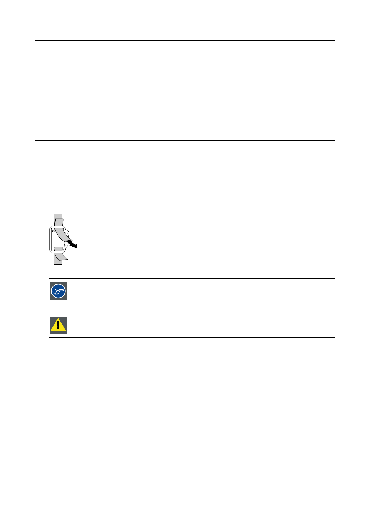
To unpack
1. Release the fastening clips.
2. Remove the banding. Handle as shown in the drawing. (image 2-1)
3. Take the projector out of its shipping carton and place it on a table.
PULL
TO OPE
Image 2-1
Save the original shipping carton and packing material, they will be necessary if you ever have to ship your
projector. For maximum protection, repack your projector as it was originally packed at the factory.
Never transport the projector with the lens mounted on it !
Always remove the lens before transporting the projector.
2.2 Box Content
Content
• 1 projector SLM R12+ (weight ± 56 kg or 123.5 lbs)
• 1 remote control unit RCU + 1 battery.
• 1 European and 1 American power cable.
• 1 Terminator for linked CLO
• 1 owners manual
• 1 safety manual
2.3 Lens Packaging
Way of Packaging
Lenses are supplied as an individual item.
R5976654 SLM R12+ 09022004
7
Page 12
2. Packaging and Dimensions
They are packed in a carton.
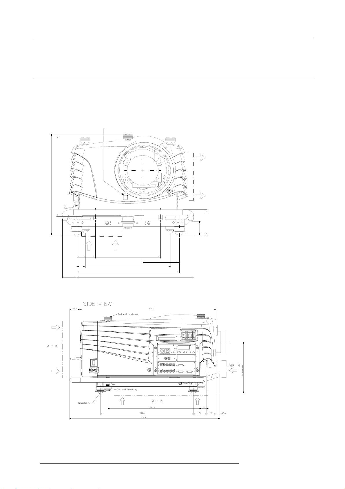
2.4 Projector Case
Dimensions
The dimensions are given in mm
25.4mm = 1 inch
IR-receiver
FRONT VIEW
372,7
466
0 456
64,5 520,5
Image 2-2
Front view dimensions
AIR IN
83 373
38 418
AIR OUT
118
64,5
162
Image 2-3
Side view dimensio ns
8 R5976654 SLM R12+ 09022004
Page 13
3. INSTALLATION GUIDELINES
Never use the projector when turned with the inputs downwards.
The engines are non sealed versions.
3.1 General
Before installing the projector, read first the safety instructions.
Ambient Temperature Conditions.
Careful consideration of things such as image size, ambient light level, project
the optimum use of the projection system.
Max. ambient temperature : 40°C or 104 °F
Min. ambient temperature : 10 °C or 50 °F
The projector will not operate if ambient air temperature falls outside this range (10°C- 40°C or 50°F-104°F).
Storage temperature: -35°C to +65°C (-31°F to 149°F)
or placement and type of screen to use are critical to
3. Installation Guidelines
Humidity Conditions
Storage: 0 to 98 % RH Non-condensing
Operation: 0 to 95 % RH Non-condensing
Harmful Environmental Contamination Precaution
Environment
Do not install the projection system in a site near heat sources such as radiators or air ducts, or in a place subject to direct sunlight,
excessive dust or humidity. Be aware that room heat rises t
excessive.
o the ceiling; check that temperature near the installation site is not
Environment condition check
A projector must always be mounted in a manner which ensures the free flow of clean air into the projectors ventilation inlets. For
installations in environments where the projector is subject to airborne contaminants such as that produced by smoke machines or
similar (these deposit a thin layer of greasy residue upon the projectors internal optics and imaging electronic surfaces, degrading
performance), then it is highly advisable and desirable to have this contamination removed prior to it reaching the projectors clean
air supply. Devices or structures to extract or shield contaminated air well away from the projector are a prerequisite, if this is not a
feasible solution then measures to relocate the projector to a clean air environment should be considered.
Only ever use the manufacturer’s recommended cleaning kit which has been specifically designed for cleaning optical parts, never
use industrial strength cleaners on the projector’s optics as these will degrade optical coatings and damage sensitive optoelectronics
components. Failure to take suitable precau
inants will culminate in extensive and irreversible ingrained optical damage. At this stage cleaning of the internal optical units will
be non-effective and impracticable. Damage of this nature is under no circumstances covered under the manufacturer’s warranty
and may deem the warranty null and void
repair. It is the clients responsibility to ensure at all times that the projector is protected from the harmful effects of hostile airborne
particles in the environment of the projector. The manufacturer reserves the right to refuse repair if a projector has been subject to
wantful neglect, abandon or improp
er use.
tions to protect the projector from the effects of persistent and prolonged air contam-
. In such a case the client shall be held solely responsible for all costs incurred during any
R5976654 SLM R12+ 09022004
9
Page 14

3. Installation Guidelines
Special Care for Laser Beams
Special care should be used when DLP projectors are used in the same room as performant laser equipment. Direct or indirect hitting
of a laser beam on to the lens can severely damage the Digital MicroMirror Devices™ in which case there is a loss of warranty
Which screen type ?
There are two major categories of screens used for projection equipment. Those used for front projected images and those for rear
projection applications.
Screens are rated by how much light they reflect (or transmit in the case of rear projection systems) given a determined amount
of light projected toward them. The ‘GAIN’ of a screen is the term used. Front and rear screens are both rated in terms of gain.
The gain of screens range from a white matte screen with a gain of 1 (x1) to a brushed aluminized screen with a gain of 10 (x10)
or more. The choice between higher and lower gain screens is largely a matter of personal preference and another consideration
called the Viewing angle. In considering the type of screen to choose, determine where the viewers will be located and go for the
highest gain screen possible. A high gain screen will provide a brighter picture but reduce the viewing angle. For more information
about screens, contact your local screen supplier.
What image size? How big should the image be?
The projector is designed for projecting an image size : min 1.00m (3.3ft) to max 15 m (49.2ft) (depending on the ambient light
conditions), with an aspect ratio of 4 to 3.
3.2 Configuration
Which configuration can be used?
The projector can be installed to project images in four different configurations:
• Front/table
• Rear/table
• Front/ceiling
• Rear/ceiling
10
R5976654 SLM R12+ 09022004
Page 15
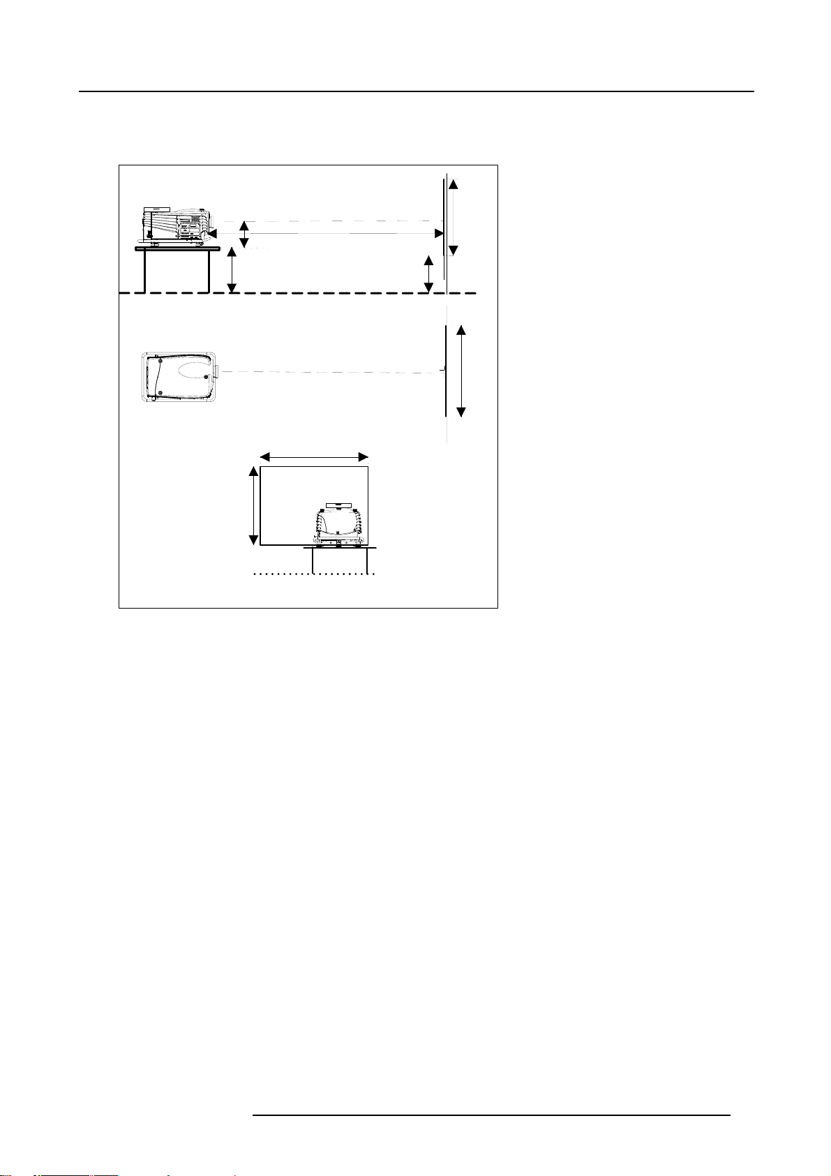
Positioning the projector
Table mounted, front projection
Table/Top side facing ceiling
Projector
A
SIDE VIEW
Optical axis projection lens
PD
Screen
3. Installation Guidelines
SH
Image 3-1
Table mounted configuration
CD
CD = SH/2 + B - A
SH
B
Floor
SW
Screen
TOP VIEW
SW
Floor
BACK VIEW
R5976654 SLM R12+ 09022004 11
Page 16
3. Installation Guidelines
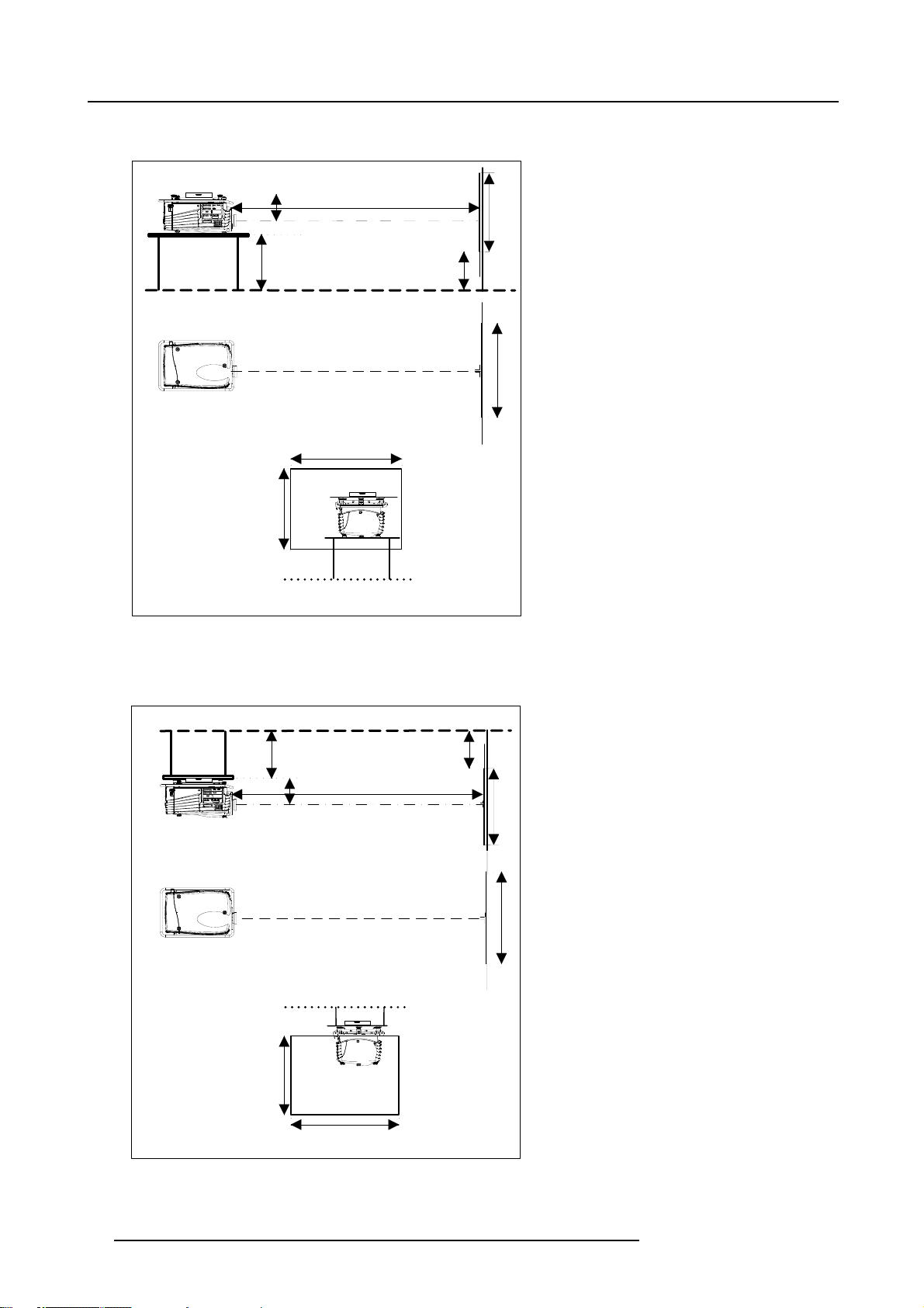
Table mounted, front projection, second way.
Table/Top side facing floor
Projector
A
SIDE VIEW
Optical axis projection lens
PD
Screen
SH
CD
CD = SH/2 + B + A - 554mm
SH
Image 3-2
Table mounted configuration up side down
Ceiling mounted, front projection
Ceiling/Top side facing floor
CD
B
Floor
SW
Screen
TOP VIEW
SW
Floor
BACK VIEW
Ceiling
B
Projector
Image 3-3
Ceiling mounted projector
A
CD = SH/2 + B - A
SH
PD
Optical axis projection lens
SIDE VIEW
CEILING VIEW
Ceiling
SW
BACK VIEW
SH
Screen
SW
Screen
12 R5976654 SLM R12+ 09022004
Page 17
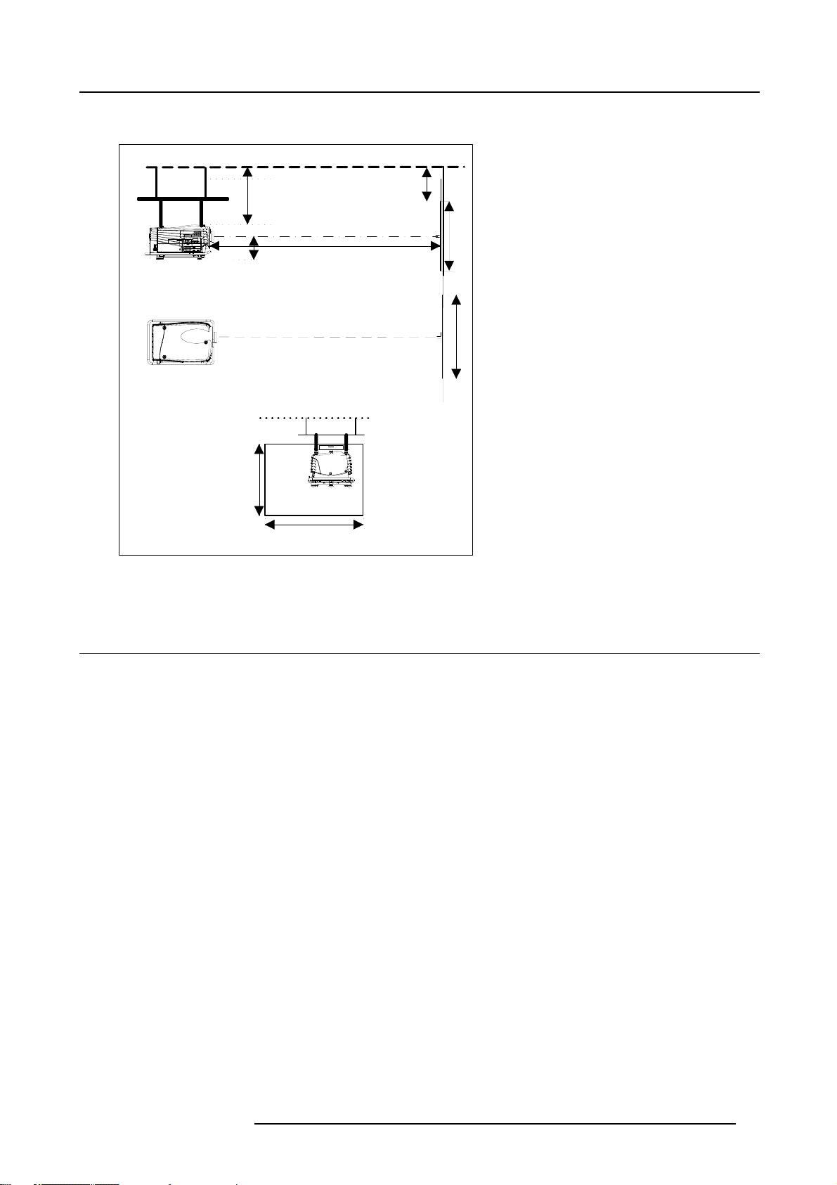
Ceiling mounted, front projection, second way.
Ceiling/Top side facing ceiling
Ceiling
3. Installation Guidelines
Projector
Image 3-4
Ceiling mounted projector
CD
A
CD = SH/2 + B + A - 554mm
Ceiling
SH
Optical axis projection lens
PD
SIDE VIEW
CEILING VIEW
SW
BACK VIEW
B
Screen
SH
SW
Screen
3.3 Safety Area around projector
Safety area
Make sure the projector is located so that the air inlets and outlets for the cooling system are not obstructed. Leave a safety area A
of about 1 meter on the left and the right side of the projector.
R5976654 SLM R12+ 09022004
13
Page 18
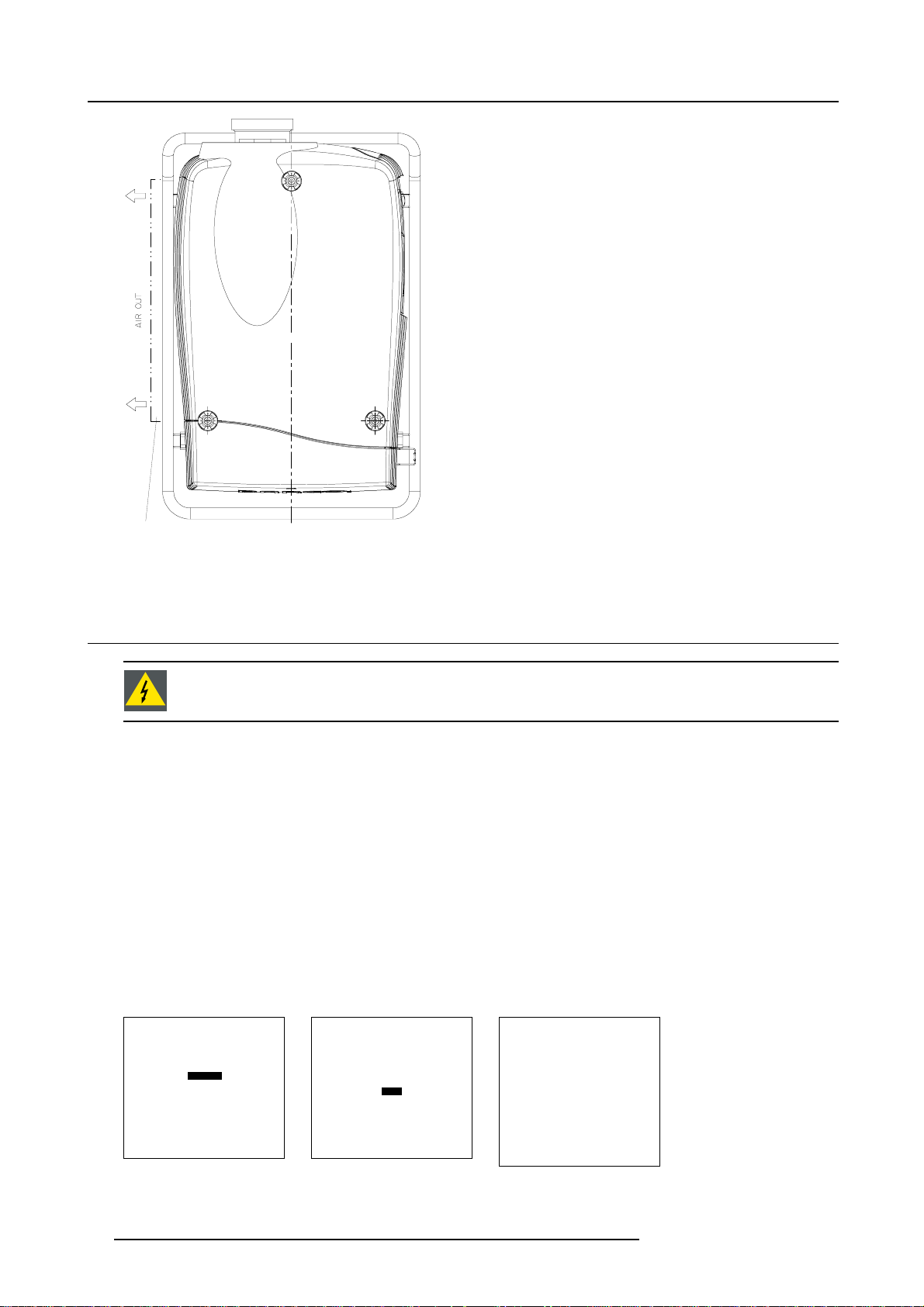
3. Installation Guidelines
A
Image 3-5
Safety a rea around th e projector
3.4 Re-adjusting the lamp position in the lamp casing
As the projector has to be opened, this procedure has to be performed by qualified service technician.
Why
With higher run times, the light output of the lamp will decrease, which results in a lower light output on the screen. This light output
decrease can be compensated by readjusting the position of the lamp.
How to readjust.
1. On the side of the inputs, turn the retaining bolt a quarter counter clockwise.
2. Flip the cover to the left side and take off. (image 3-6)
3. Start up the adjustment mode and select Service. (menu 3-1)
4. Select Lamp. The Z-axis indication (lamp menu in service mode) will be helpful while turning screw B . (menu 3-2)
5. Loosen the nut A (image 3-7)on the back of th
6. Adjust the screw B (image 3-7)with an Allen key by turning a little clockwise until the maximum light output is reached (the maximum value of the Z-AXIS indication on the lamp menu).
7. Fasten the nut on the back of the lamp casing to secure this position (nutdriver 10).
ADJUSTMENT MODE
Select a path from below :
RANDOM ACCESS
Menu 3-1
INSTALLATION
SERVICE
Select with ↑ or ↓
then <ENTER>
<EXIT> to return
CHANGE PROJ. ADDRESS
SERIAL COMMUNICATION
Select with ↑ or ↓
Menu 3-2
e lamp casing (nutdriver 10).
SERVICE
IDENTIFICATION
CHANGE PASSWORD
CHANGE LANGUAGE
NETWORK
LAMP
DIMMING
MORE...
then <ENTER>
<EXIT> to return
LAMP
Constant Light output [OFF]
Mode [NORMAL]
Serial number : R101111
Article number : R9840xxx
Run time : 10 hours
Remaining run time : 490
Menu 3-3
hours
Number of strikes : 10
Z_AXIS : 100
Select with ↑ or ↓
then <ENTER>
<EXIT> to return.
14 R5976654 SLM R12+ 09022004
Page 19
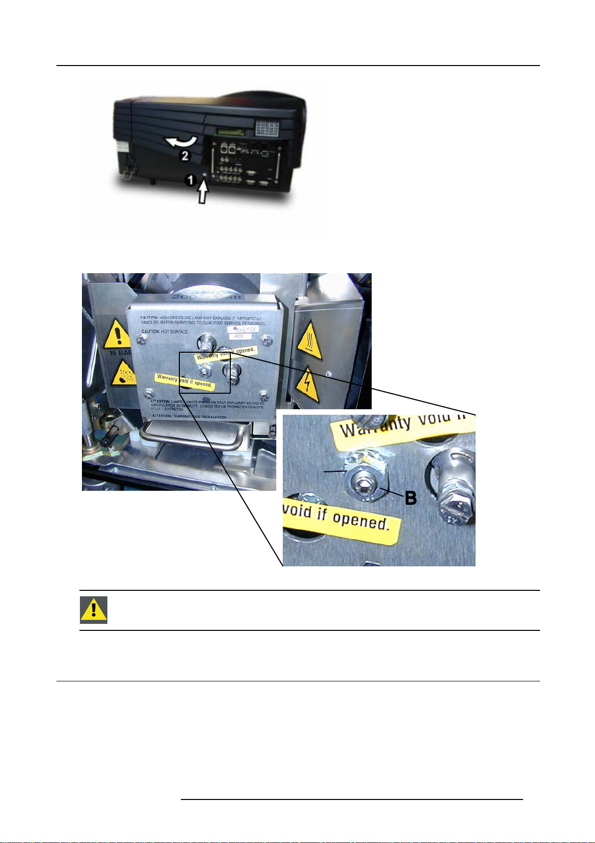
Image 3-6
Lamp adjustment access
3. Installation Guidelines
Image 3-7
3.5 Lenses
Overview
• Lenses
• Lens selection
• Lens formulas
• Lens Installation
• Cleaning the lens
A
Never turn the other screws ! These are factory aligned.
R5976654 SLM R12+ 09022004
15
Page 20
3. Installation Guidelines
3.5.1 Lenses
Available lenses
TLD(1.6–2.0:1)
TLD(2.0–2.8:1)
TLD(2.8–5.0:1)
TLD(1.2:1)
TLD(0.8:1)
TLD(5.0–8.0:1)
TLD HB(0.8:1)
TLD HB(1.6–2.0:1)
TLD HB(2.0–2.8:1)
TLD HB(2.8–5.0:1)
TLD HB(5.0–8.0:1)
R9840670
R9840680
R9840690
R9840770
R9840900
R9840910
R9842040
R9842060
R9842080
R9842100
R9842120
3.5.2 Lens selection
How to select ?
1. Determine the required screen width.
2. Determine the approximate position of the project
screen distance (PD).
3. Use the lens formulas to find the best corresponding PD with regard to the measured projector-screen distance for the required
screen width.
or in the projection room with regard to the screen and measure the projector-
3.5.3 Lens formulas
Formulas
Metric formulas (meter) Inch formulas (inch)
TLD(0.8:1) PD=0.85xSW-0.05 PD=0.85SW-1.97
TLD(1.2:1) PD=1.22xSW-0.01 PD=1.22xSW-0.39
TLD(1.6–2.0:1) PD
TLD(2.0–2.8:1) PD
TLD(2.8–5.0:1) PD
TLD(5.0–8.0:1) PD
TLD HB(0.8:1) PD=0.85xSW-0.05 PD=0.85SW-1.97
TLD HB(1.2:1) PD=1.22xSW-0.01 PD=1.22xSW-0.39
TLD HB(1.6–2.0:1) PD
=1.62xSW-0.09
min
PD
=2.03xSW-0.13
max
=2.03xSW-0.17
min
PD
=2.88xSW-0.24
max
=2.84xSW-0.16
min
=5.18xSW-0.38
PD
max
=4.97xSW-0.01
min
=8.28xSW-0.29
PD
max
=1.62xSW-0.09
min
=2.03xSW-0.13
PD
max
PD
PD
PD
PD
PD
PD
PD
PD
PD
PD
=1.62xSW-3.54
min
=2.03xSW-5.12
max
=2.03xSW-6.69
min
=2.88xSW-9.45
max
=2.84xSW-6.30
min
=5.18xSW-14.96
max
=4.97xSW-0.39
min
=8.28xSW-11.42
max
=1.62xSW-3.54
min
=2.03xSW-5.12
max
TLD HB(2.0–2.8:1) PD
=2.03xSW-0.17
min
=2.88xSW-0.24
PD
max
PD
=2.03xSW-6.69
min
=2.88xSW-9.45
PD
max
16 R5976654 SLM R12+ 09022004
Page 21
3. Installation Guidelines
Metric formulas (meter) Inch formulas (inch)
TLD HB(2.8–5.0:1) PD
TLD HB(5.0–8.0:1) PD
=2.84xSW-0.16
min
=5.18xSW-0.38
PD
max
=4.97xSW-0.01
min
=8.28xSW-0.29
PD
max
PD
=2.84xSW-6.30
min
=5.18xSW-14.96
PD
max
PD
=4.97xSW-0.39
min
=8.28xSW-11.42
PD
max
3.5.4 Lens Installation
How to install ?
Follow the next procedure:
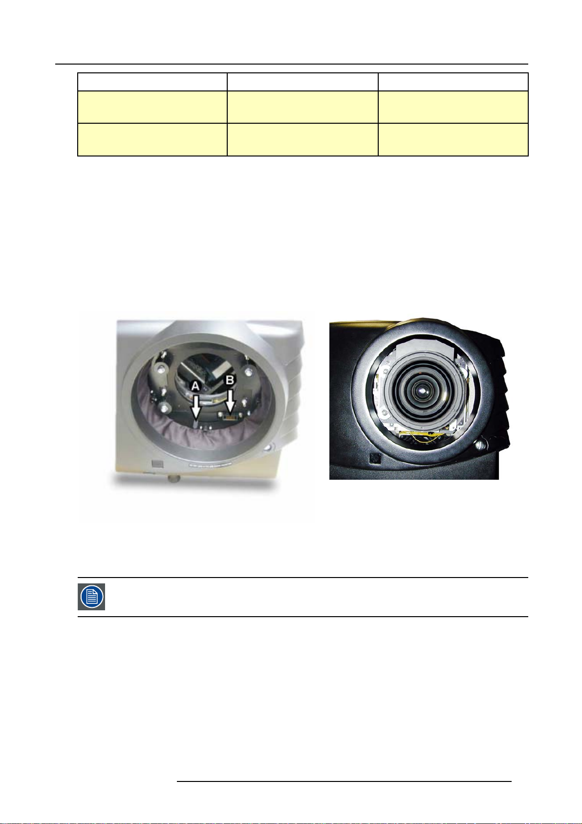
1. Remove the foam rubber in the opening of the lens holder.
2. Take the lens assembly out of its packing material a
3. Move the handle (A) of the lens anchor system to the right. (image 3-8)
4. Push the lens, motors at the top, in the lens block gap horizontally, lining up the motor connector on the lens with the connector
on the lens block (B), until the lens clicks in the lens anchor system. (image 3-9)
Caution: On a table mounted projector, hold the projector whe
the table.
nd remove the lens caps on both sides.
n pushing the lens into the lens block to avoid sliding off from
Image 3-9
Mounted Lens
Image 3-8
Lens installat
ion
3.5.5 Cleaning the lens
To minimize the possibility of damaging the optical coating or scratching exposed lens surface, we have developed recommendations for cleaning the lens. FIRST, we recommend you try to remove any material from
the lens by blowing it off with clean, dry deionized air. DO NOT use any liquid to clean the lenses.
Necessary tools
To ra ys e eTMcloth (delivered together with the lens kit). Order number : R379058.
Howtocleanthelens?
Proceed as follow :
TM
1. Always wipe lenses with a CLEAN Toraysee
2. Always wipe lenses in a single direction.
Warning: Do not wipe back and forwards across the lens surface as this tends to grind dirt into the coating.
3. Do not leave cleaning cloth in either an open room or lab coat pocket, as doing so can contaminate the cloth.
4. If smears occur when cleaning lenses, replace the cloth. Smears are the first indication of a dirty cloth.
cloth.
R5976654 SLM R12+ 09022004
17
Page 22
3. Installation Guidelines
Do not use fabric softener when washing the cleaning cloth or softener sheets when drying the cloth.
Do not use liquid cleaners on the cloth as doing so will contaminate the cloth.
Other lenses can also be cleaned safely with this TorayseeTMcloth.
3.6 Battery Installation in the RCU
How is the battery delivered ?
A battery (not yet installed to save the battery life time) is delivered inside the plastic bag with the power cord.
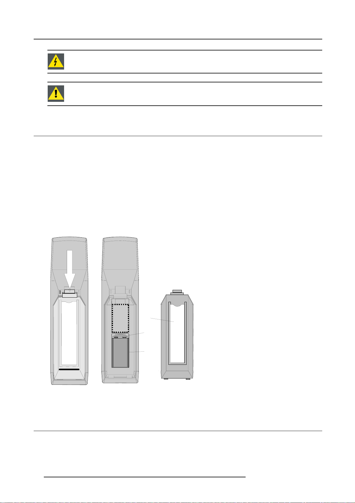
How to install ?
1. Remove the battery cover on the backside of the remote control by pushing the indicated handle a little towards the bottom of
the RCU. (image 3-10)
2. Lift up the top side of the cover at the same time.image 3-10
3. Insert the new 9 V battery (type E-block or equivalent) in the lower compartment.
4. Connect the battery (B) to the contact plate (A). (image 3-11)
5. Insert the battery into the lower compartment and put the cover back.
6. Insert a overview card (C) in the back side.image 3-11
C
A
B
Image 3-10
Opening the battery cover of
the RCU
Image 3-11
Mounting the battery into the RCU
3.7 Stacking Projectors
What is possible?
Up to 3 projectors can be stacked on each other without using extra tools or accessories.
18
R5976654 SLM R12+ 09022004
Page 23
3. Installation Guidelines
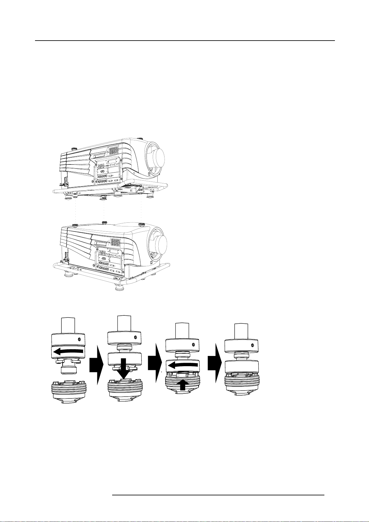
How to stack?
Handle as follow:
1. Put the second projector on the first one so that base plate of the second projector matches with the rigging socket of the first
projector. (image 3-12)
2. Turn the rigging sockets of the second projector counter clockwise until they are free to move up and down. (image 3-13)
3. Secure the projectors on each other by bringing the free part of the second projector into the socket of the first projector and turn
a quarter clockwise while pushing downwards until it clicks in.
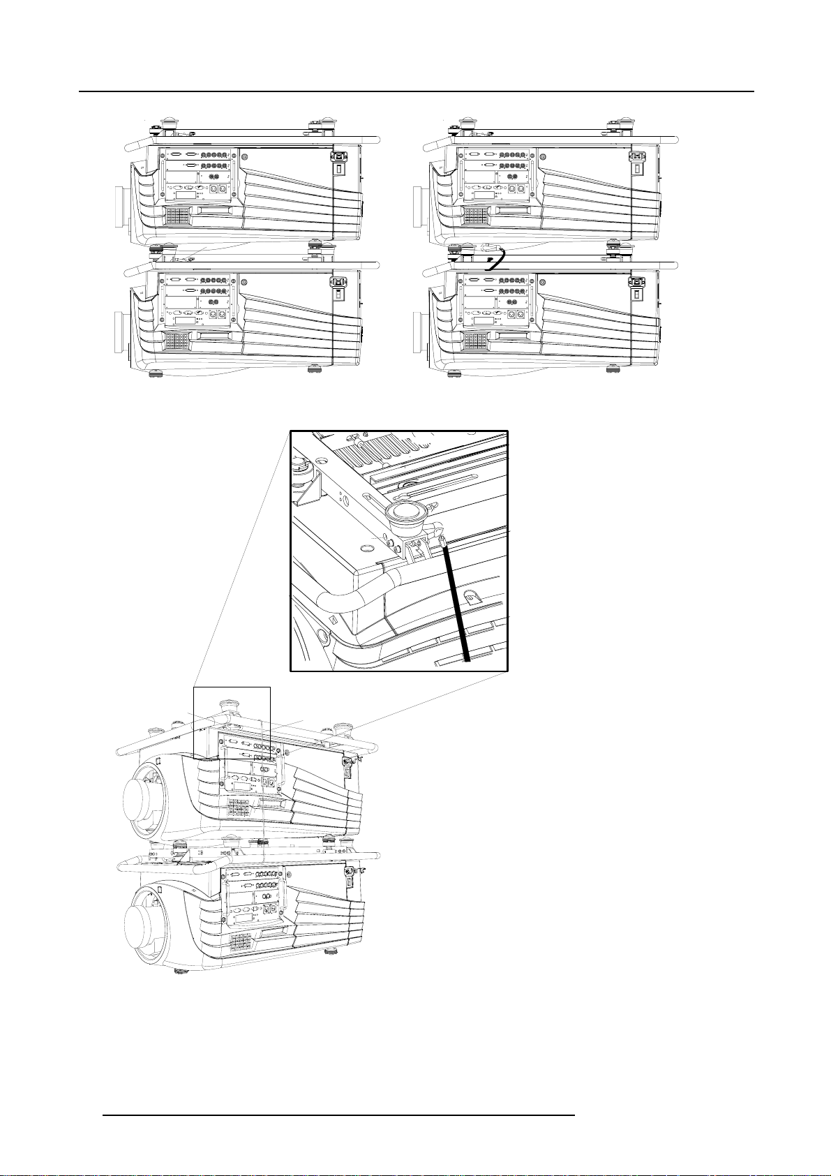
4. For ceiling mounted configurations, pull on the hook (A) with the cable of the lowest projector. (image 3-14)
5. Guide hook and cable around the carry handle and guide it around the carry handle of the upper projector. (image 3-15)
6. Hook it in the foreseen hole B in the base plate of the upper projector. (image 3-16)
Image 3-12
Stacking two projectors
Image 3-13
Closing the rigging sockets
R5976654 SLM R12+ 09022004 19
Page 24
3. Installation Guidelines
A
Image 3-14
Mounting the security chain
B
Image 3-15
Mounting the security hook
B
C
Image 3-16
Mounting the security hook (detail)
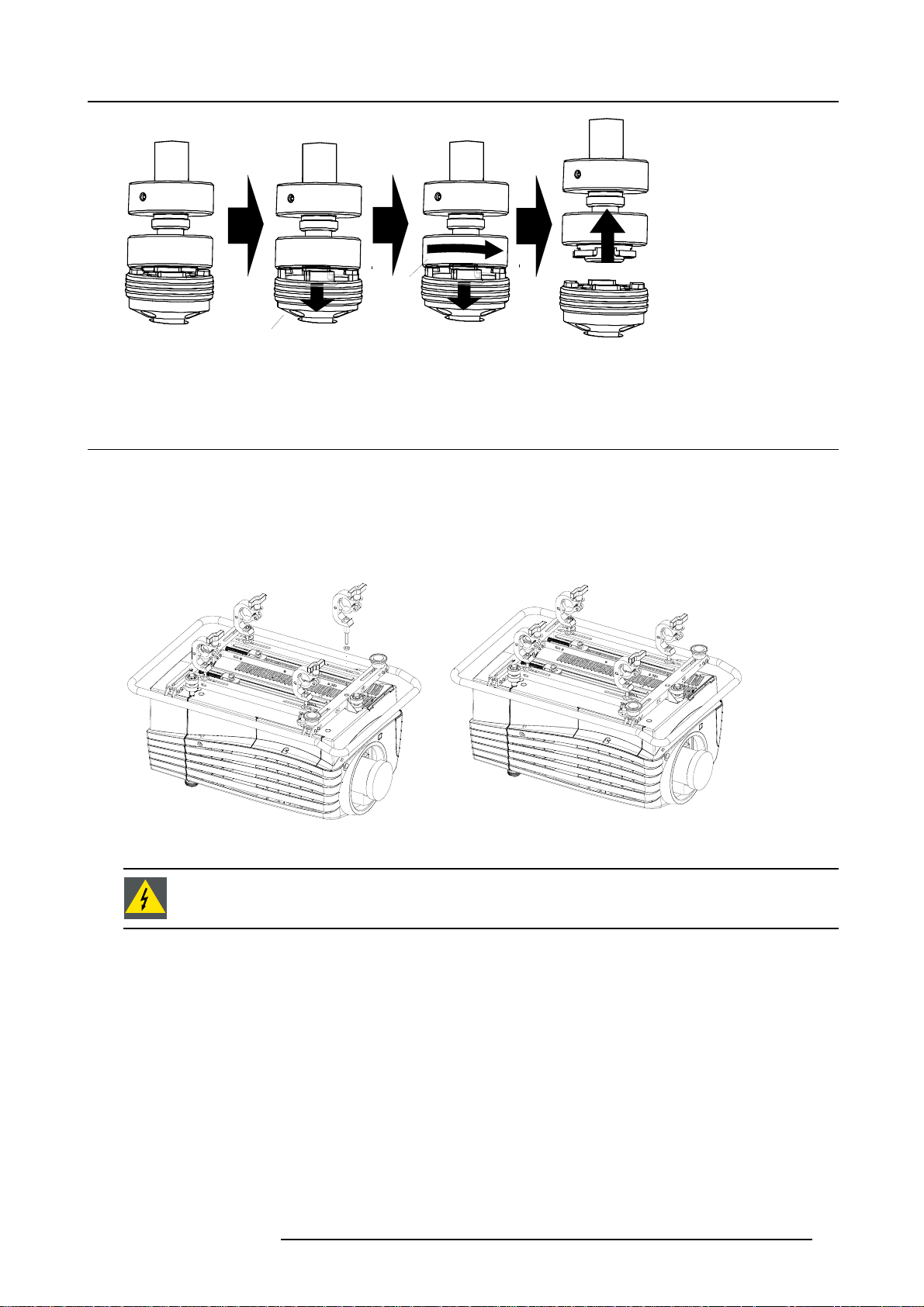
How to open a secured rigging point?
1. Push the ring (A) of the first projector downwards and hold it in that position. (image 3-17)
2. Turn the locked part (B) of the second projector a quarter counter clockwise and move it upwards.
20
R5976654 SLM R12+ 09022004
Page 25
3. Installation Guidelines
B
A
Image 3-17
Opening the rigging sockets
3.8 Rigging points and Accessories
Clamps
Slots are made in the carry handle frame for easy inserting the overlockers and for easy adjusting the clamps position so that this
position matches with the rigging points.
Consult a professional structural engineer prior to suspending the ceiling mount from a structure not intended for that use. Always
ensure the working load limit of the structure supporting the projector
.
Image 3-19
Image 3-18
Mounting the clamps
When mounting the projector to the ceiling or to a rigging system, always mount security chains.
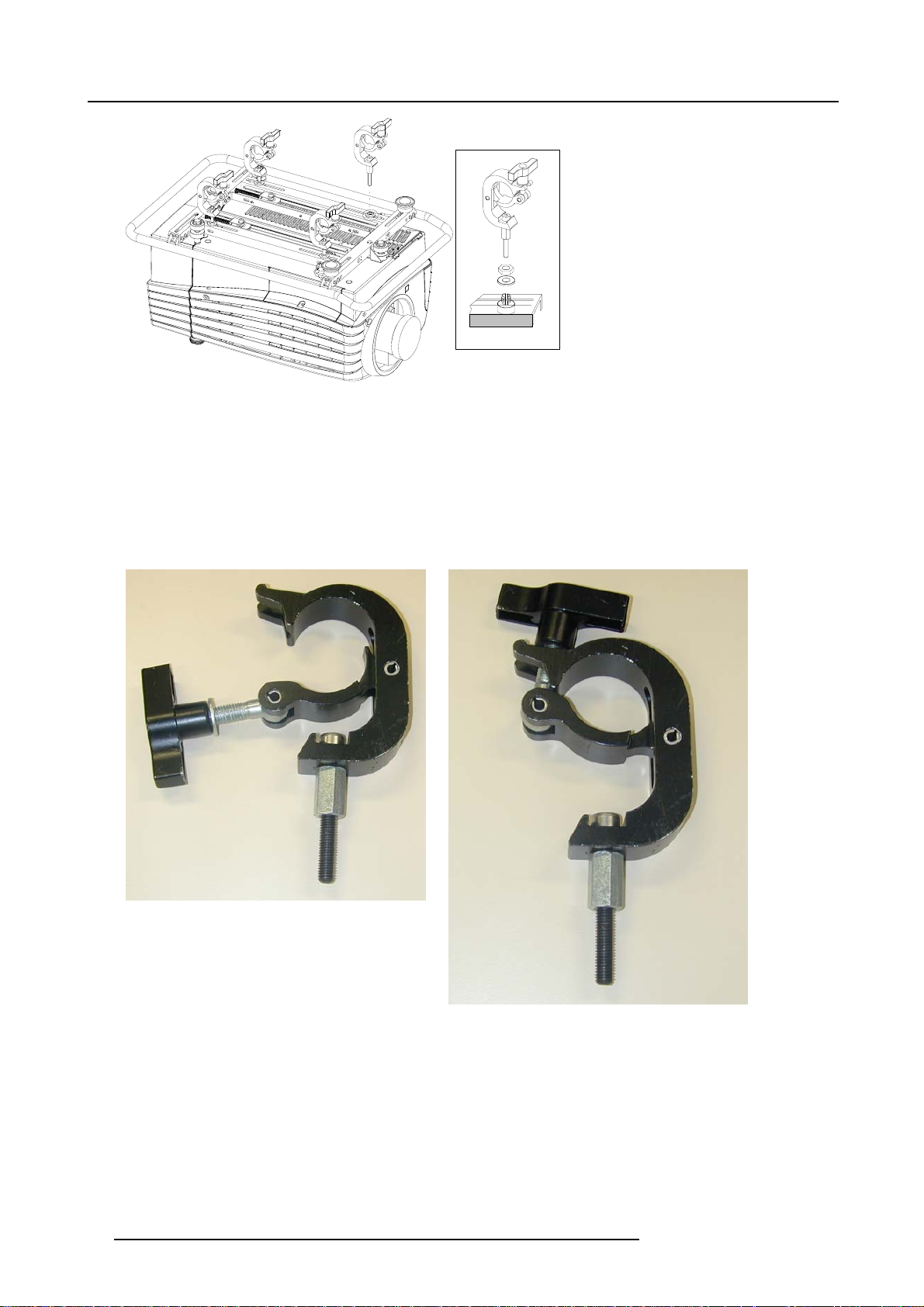
Mounting the clamps
How to mount the clamps?
To fix the clamps to the U-profile, follow the next procedure :
1. Measure the distance, center tube as reference, between the two used support bars of a truss.
2. Slide the clamps holders (2 per profile) on its place in the U-profile according the measured distance and secure this position.
(image 3-20)
3. Turn the overlockers in the holes of the clamp holder.
The overlocker can turn around.
R5976654 SLM R12+ 09022004
21
Page 26
3. Installation Guidelines
Image 3-20
Mounting the clamp — detail
How to mount the Overlockers to the truss?
To mount the overlocker to the truss, handle as follow :
1. Open the fixation handle. (image 3-21)
2. Hook the clamp around the tube.
The trigger automatically shuts the clamp.
3. Close the fixation handle and secure it by turning the hand screw. (image 3-22)
Image 3-21
Opening the rigging clamp
Image 3-22
Closing the rigging clamp
22 R5976654 SLM R12+ 09022004
Page 27
4. Connections
4. CONNECTIONS
Overview
• Power connection
• Switching on
• Switching to standby
• Switching off
• Input Source Connections
• Communication Connections
4.1 Power connection
AC Power cord connection
Use the supplied power cord to connect your projector to the wall outlet. Plug the female power connector into the male connector
at the left of the projector. The power input is 230 VAC.
Fuses
The projector is protected with an automatic circuit breaker of 15A which is built in into the power switch.
4.2 Switching on
How to switch on.
1. Press the power switch to switch on the projector.
- When ’0’ is visible, the projector is switched off.
- When ’1’ is visible, the projector is switched on
The projector starts in standby mode. The projector indication lamp is red.
Starting image projection.
1. Press Stand by key once on the local keypad or on the remote control.
The projector mode indication lamp will be green (image 4-1)
Or,
Press a digit button to select an input source.
EXIT
ADJ
ENTER
FREEZTEXT
STBY
PAUSE
-
HELP
+
PHASE
?
-
+
0
SHARPNESS
9
-
+
7
TINT
8
-
+
6
5
COLOR
-
+
4
3
BRIGHTNESS
-
+
21
CONTRAST
32a
0
9
7
8
6
5
3
4
2
1
Image 4-1
Standby indication
STANDBY
TEXT
SHARPN
PHASE
ENTER
TINT
COLOR
A
EXIT
PAUSE
BRIGHTN
CONTRAST
R5976654 SLM R12+ 09022004 23
Page 28
4. Connections
Lamp run time indication while running
When the total run time of the lamp is 30 hours less then 500, the following warning message will be displayed for 1 minute. This
warning message will be repeated every 30 minutes. Press EXIT to remove the message before the minute is over.
Remaining
Lamp run time
20h
Image 4-2
When the total run time of the lamp is 500 hours or more, the following warning message, with the exact run time is displayed on
the screen.
WARNING
Lamp run time is x hours
operating the lamp longer
than x hours may damage
the projector.
Please replace the lamp
<ENTER> to continue
Menu 4-1
Lamp run time is 500 hours. Operating the lamp longer than 1000 hours may damage the projector. Please re
When ENTER is pressed to go on, the warning will be repeated every 30 min.
The total lifetime of the lamp for a safe operation is 500 hours max. Do not use it longer. Always replace with a same type of lamp.
Call a BARCO authorized service technician for lamp replacement.
place the lamp.
Using a lamp for more than 500 hours is dangerous as the lamp could explode.
Lamp Light Output Indication
When starting up and the center lumens measurement is lower than 50 % of its ini
displayed. Press ENTER to continue. The message will not be repeated during operation.
WARNING
Lamp run time is X hours
The light output of the lamp
than 50% of its initial value.
It is advisable to replace the
Menu 4-2
is less
lamp
before damage occurs.
<ENTER> to confirm
When the ’Constant Light Output’ (CLO) options is installed, the light output message will appear on the screen when the light output
is reduced with 33% from its initial value.
This message will be repeated every hour.
tial value, the lamp light output warning will be
Lamp Z-axis indication
When starting up and the run time is 100 hours or 250 hours a Z-axis warning will be displayed. This warning will advise to adjust the
Z-axis of the lamp to obtain maximum light output. Press ENTER to continue. The message will not be repeated during operation.
WARNING
Lamp run time is X hours.
It is advisable to
adjust the Z-axis
of the lamp to
obtain maximum
light output
(see owner’s manual)
<ENTER> to confirm
Menu 4-3
24 R5976654 SLM R12+ 09022004
Page 29
4.3 Switching to standby
Howtoswitchtostandby?
1. Press Standby to switch the projector to standby.
4.4 Switching off
How to switch off the projector?
1. Press first Standby.
2. Let cool down the projector until the fans stop blowing, at least 15 min.
3. Switch off the projector with the power switch.
4.5 Input Source Connections
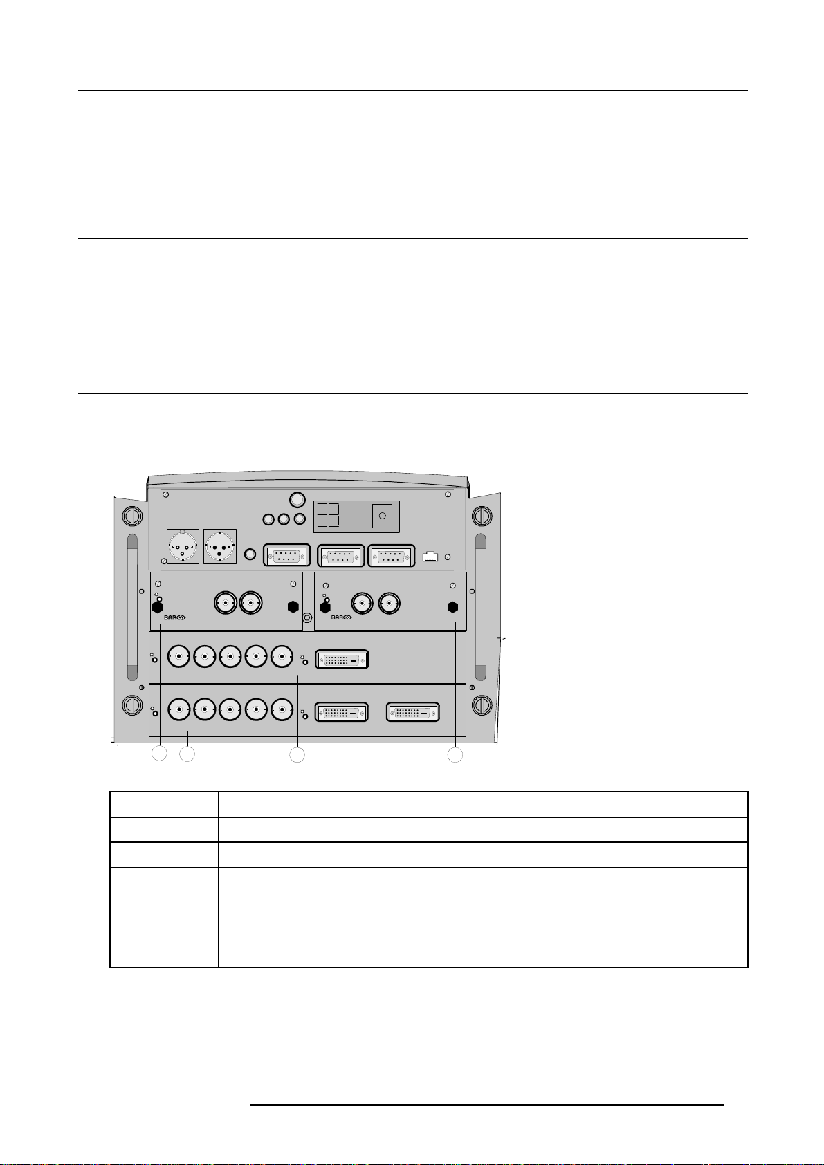
4.5.1 Input Facilities
Overview input facilities
4. Connections
IR-ReceiverDiagnostic Code
COMM PORT 10/(100)base-T
OUTIN
R9840450
HD SDI DIGITAL MODULE
DVI OUTPUT
4
On
On
3
Image 4-3
Input facilities
Input number
Green Operation
OUT IN
Red Stand-by
Hardwired
remote
CTRL 1
H/C V
H/C V
Two way
Hardwired
hardwired
remote
remote
CTRL 2
CTRL 3
On
SDI DIGITAL INPUT
GB
R
High Bandwidth 5 CABLE INPUT
GB
R
High Bandwidth 5 CABLE INPUT
1
Type of input
RS232/422 IN
IRSync OK
RS232/422 OUT
On
9840110
On
DVI INPUT
On
DVI INPUT
2
1 Fixed input, 5 cable input or DVI input and DVI output
2 Fixed input, 5 cable input or DVI input
3&4
Variable inputs
Two digital inputs available.
• SDI input (R9840110)
• HD SDI Digital input (R9840450)
Digital Video Decoder (R9841170)
4.5.2 Inputs via RCVDS05
Overview
When using a RCVDS05, the input configuration must be as follows:
R5976654 SLM R12+ 09022004
25
Page 30
4. Connections
slot 1
RGB/Component
slot 2 Video
slot 3 not used
slot 4 not used
When using a RCVDS05, it is recommended to use a 5-cable output module in the RCVDS. The outputs of this module has to be
connected to slot 1 of the projector. To switch the projector in the 5-cable mode see Fixed slot (slot 1 & 2), page 27.
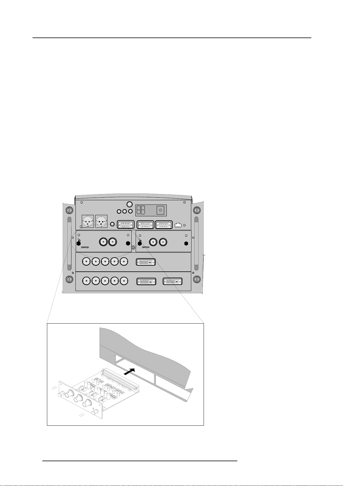
4.5.3 Input module insertion
How to insert an input module?
Toinsertamoduleinoneofthefreeslots,handleasfollow:
1. Power down the projector and disconnect the power cord from the wall outlet.
2. Remove the dummy plate covering the chosen input slot by turning out both screws.
3. Slide the input module in the free slot. Insure the module is seated correctly in the guide grooves.
4. Press on both handles of the input module until the module plug seats in the connector of the projector. (image 4-4)
RS232/422 OUT
ng screws.
IR-ReceiverDiagnostic Code
COMM PORT 10/(100)BASE-T
5. Secure the input module by tightening both retaini
6. Reconnect the power cord to the wall outlet and switch on the projector.
Green Operation
Hardwired
remote
CTRL 2
Hardwired
remote
CTRL 1
Red Stand-by
RS232/422 IN
IRSync OK
Two way
hardwired
remote
CTRL 3
On
R
High Bandwidth 5 CABLE INPUT
R
High Bandwidth 5 CABLE INPUT
OUT IN
SDI DIGITAL INPUT
GB
GB
H/C V
On
9840110
DVI INPUT
VH/C
DVI INPUT
OUTIN
R9840450
HD SDI DIGITAL MODULE
DVI OUTPUT
Image 4-4
26 R5976654 SLM R12+ 09022004
Page 31

4. Connections
How to select the new installed module?
The new installed module can be selected with the digit buttons on the RCU or the local keypad.
4.5.4 Fixed slot (slot 1 & 2)
Where to find?
Slot 1 & 2 has 5 BNC input terminals for 5 cable input and a DVI plug for DVI input. Slot 1 has also an DVI output for loop through
to a second projector. Within the installation mode it is possible to setup the input for 5 cable or DVI (PanelLink).
Which signals can be connected to slot 1 & 2?
Connector name/
Input signal
RGBHV
RGBS
RGsB
Composite Video
Super Video
Component Video — SS
Component Video — SOY
DVI signals can be connected to the DVI input connector.
Pin assignment for the DVI connector.
Pin 1
Pin 2
Pin 3
Pin 4
Pin 5
TMDS DATA2-
TMDS DATA2+
TMDS DATA2/4 Shield
TMDS DATA4-
TMDS DATA4+
R
R
R
R
-
-
R-Y Y B-Y
R-Y Ys B-Y
G
G
G
Gs
Video
Y
Pin 13
Pin14 +5Power
Pin 15
Pin 16 Hot Plug Detect
Pin 17
B H V
B H V
B
B
- - -
- -
TMDS DATA3+
Ground (for +5V)
TMDS DATA0-
S
- -
S
- -
-
C
-
Pin 6
Pin 7
Pin 8 No connect Pin 20
Pin 9
Pin 10
Pin 11
Pin 12
DDC Clock
DDC Data
TMDS DATA1-
TMDS DATA1+
TMDS DATA1/3 Shield
TMDS DATA3-
Pin 18
Pin 19
Pin 21
Pin 22
Pin 23
Pin 24
How to select input slot 1 or 2 ?
1. Key in 1 or 2 on the RCU or the local keypad.
How to change the input slot setting?
1. Press ADJUST or ENTER key to start up the Adjustment mode.
h the cursor key ↑ or ↓ to select Installation. (menu 4-4)
2. Pus
3. Press ENTER.
4. Press the cursor key ↑ or ↓ to select Input Slots. (menu 4-5)
TMDS DATA0+
TMDS DATA0/5 Shield
TMDS DATA5-
TMDS DATA5+
TMDS Clock Shield
TMDS Clock+
TMDS Clock-
R5976654 SLM R12+ 09022004
27
Page 32

4. Connections
5. Press ENTER.
The internal system will scan the inputs and displays the result in the Input Slots menu.
6. Push the cursor key ↑ or ↓ to select the first or second slot. (menu 4-6)
ADJUSTMENT MODE
Select a path from below :
RANDOM ACCESS
INSTALLATION
SERVICE
Select with ↑ or ↓
then <ENTER>
<EXIT> to return
Menu 4-4
Menu 4-5
INSTALLATION
INPUT SLOTS
800 PERIPHERAL
SOURCE SWITCHING
NO SIGNAL
CONTRAST ENHANCEMENT
CONVERGENCE
CONFIGURATION
LENS
QUICK ACCESS KEYS
OSD
INTERNAL PATTERNS
Select with ↑ or ↓
then <ENTER>
<EXIT> to return
INPUT SLOTS
Slot Module type [config]
1. RGB-SS [CV]
2. RGB-SOG
3. SDI
4. SDI
______________
1. DVI OUTPUT [DVI input]
Select with ↑ or ↓
then <ENTER>
<EXIT> to return
Menu 4-6
Possible indications on the input slot menu.
For the input side:
• RGS-SS [CV or HS&VS] = RGB analog signals, separate sync is composite sync or horizontal and vertical sync.
• RGB-SS [CV] = RGB analog signals, separate sync is composite video.
• RGB-SOG [SOG or 3LSOG] = RGB analog signals, sync on green is composite sync or composite tri-level sync.
• COMPONENT VIDEO - SS [SS or 3LSS] = separate sync is composite sync or composite tri-level sync.
• COMPONENT VIDEO - SOY [SOY or 3LSOY] = component video with composite sync on Y or composite tri-level s
•VIDEO
•S-VIDEO
•DVI
When changing from an analog signal on the 5 cable module to the PanelLink input the indication led on the front panel of the module
will switch from the 5 cable input to the DVI (PanelLink) input also.
For the output on fixed slot 1:
• DVI input : DVI in signal is looped through to the DVI out connector as it is.
• Active image : active image signal, what ever the input is, is available in DVI on the DVI output signal (processing is incorporated
in the signal). Set the minimum delay in Inst allation > Advanced processing to OFF.
• DVI resync : DVI in signal is resyncronized with a stable clock and put on the DVI out connector
ync on Y.
When using an RCVDS 05 with a 5 cable output module, connect these 5 cables to this fixed 5
-input slot (slot
1) of the projector. All sources of the RCVDS can now be accepted by the projector.
4.5.5 Serial Digital Input (slot 3 & 4)
What can be connected to this input?
This input is full compatibility with digital Betacam, or other digital video sources. This avoids the need for analog video processing
anywhere in the video production chain and guarantees the ultimate image quality.
An active loop-through of the SDI input signal is provided for monitoring or for double and or triple stacking applications.
How to connect ?
1. Connect the output of your SDI source to the input BNC of the SDI input. (image 4-5)
Note: The input is always 75 Ω terminated.
2. If loop through is needed, use the OUT to connect to the next device.
28
R5976654 SLM R12+ 09022004
Page 33

4. Connections
Image 4-5
Two way
Hardwired
hardwired
remote
remote
CTRL 2
CTRL 3
On
R
On
Hardwired
remote
CTRL 1
OUT IN
SDI DIGITAL INPUT
GB
H/C V
High Bandwidth 5 CABLE INPUT
R
GB
H/C V
High Bandwidth 5 CABLE INPUT
Digital
Video
DIGITAL VIDEO SOURCE
Green Operation
Red Stand-by
RS232/422 IN
IR-ReceiverDiagnostic Code
IRSync OK
RS232/422 OUT
On
9840110
On
COMM PORT TRIGGER OUT
OUTIN
R9840450
HD SDI DIGITAL MODULE
DVI INPUT
OnOn
DVI INPUT
DVI OUTPUT
How to select the digital input?
1. Key in the corresponding slot number on the RCU or the local keypad.
When a RCVDS05 is connected to the projector, the SDI input is available by keying in 83 or 84 on the RCU.
4.5.6 HD SDI Digital input (slot 3 & 4)
What can be connected to this input?
This input is full compatibility with HD digita
production chain and guarantees the ultimate image quality.
An active loop-through of the HD SDI input signal is provided for monitoring or for double and or triple stacking applications.
l sources. This avoids the need for analog video processing anywhere in the video
How to connect ?
1. Connect the output of your HD SDI source to the input BNC of the HD SDI input. (image 4-6)
Note: The input is always 75 Ω terminated.
2. If loop through is needed, use the OUT to connect to the next device.
R5976654 SLM R12+ 09022004
29
Page 34

4. Connections
Image 4-6
Two way
Hardwired
hardwired
remote
remote
CTRL 2
CTRL 3
On
R
On
Hardwired
remote
CTRL 1
OUT IN
SDI DIGITAL INPUT
GB
H/C V
High Bandwidth 5 CABLE INPUT
R
GB
H/C V
High Bandwidth 5 CABLE INPUT
Green Operation
Red Stand-by
IRSync OK
9840110
RS232/422 OUT
On
On
RS232/422 IN
DVI INPUT
OnOn
DVI INPUT
Digital
Video
DIGITAL VIDEO SOURCE
IR-ReceiverDiagnostic Code
TRIGGER OUT
COMM PORT
OUTIN
HD SDI DIGITAL MODULE
DVI OUTPUT
R9840450
How to select the digital input?
1. Key in the corresponding slot number on the RCU or the local keypad.
When a RCVDS05 is connected to the projector, the SDI input is available by keying in 83 or 84 on the RCU.
4.5.7 Digital Video Decoder Input
What can be connected to this input?
The following source types can be connected:
•S-Video
• Component Video
• Composite Video
Which signal can be connected to the Digital Video Decoder module?
Connector name/
Input signal
Component Video
Composite Video
S-Video
Pb
Y/Vid
B-Y Ys R-Y
-
Video
- - -
Pr
- -
S-Video
-
S-Video
How to connect?
1. Connect
30
the output of your source to the corresponding inputs on the Digital Video Decoder module. (image 4-7)
R5976654 SLM R12+ 09022004
Page 35

4. Connections
IR-ReceiverDiagnostic Code
COMM PORT
HD SDI DIGITAL MODULE
Ethernet
OUTIN
DVI OUTPUT
R9840450
Two way
Hardwired
hardwired
remote
remote
CTRL 2
CTRL 3
On
R
On
P
R
DIGITAL VIDEO DECODER
Hardwired
remote
CTRL 1
Y/Vid
GB
High Bandwidth 5 CABLE INPUT
GB
R
High Bandwidth 5 CABLE INPUT
1
2
Green Operation
Red Stand-by
S-Video
PB
H/C V
H/C V
RS232/422 IN
3
IRSync OK
RS232/422 OUT
On
On
DVI INPUT
OnOn
DVI INPUT
Image 4-7
1 Component video input
2 Composite Video input
3 S-Video input
How to select the digital video decoder input?
1. Key in the corresponding slot number on the RCU or the local keypad.
How to change the input slot setting?
1. Press ADJUST or ENTER key to start up the Adjustment mode.
2. Push the cursor key ↑ or ↓ to select Installation. (menu 4-7)
3. Press ENTER.
4. Press the cursor key ↑ or ↓ to select Input Slots. (menu 4-8)
5. Press ENTER.
The internal system will scan the inputs and displays the result in the Input Slots menu.
6. Push the cursor key ↑ or ↓ to select the third or fourth sl
7. Press ENTER to toggle.
Possible indications on the input slot menu.
- VIDEO[VDEO]
- VIDEO[S-VIDEO]
- VIDEO[YUV]
ot. (menu 4-9)
ADJUSTMENT MODE
Select a path from below :
RANDOM ACCESS
INSTALLATION
SERVICE
Select with ↑ or ↓
then <ENTER>
<EXIT> to return
Menu 4-7
Menu 4-8
INSTALLATION
INPUT SLOTS
800 PERIPHERAL
SOURCE SWITCHING
NO SIGNAL
CONTRAST ENHANCEMENT
CONVERGENCE
CONFIGURATION
LENS
QUICK ACCESS KEYS
OSD
INTERNAL PATTERNS
Select with ↑ or ↓
then <ENTER>
<EXIT> to return
INPUT SLOTS
Slot Module type [config]
1. RGB-SS [CV]
2. RGB-SOG
3. SDI
4. SDI
______________
1. DVI OUTPUT [DVI input]
Select with ↑ or ↓
then <ENTER>
<EXIT> to return
Menu 4-9
R5976654 SLM R12+ 09022004 31
Page 36

4. Connections
4.6 Communication Connections
Overview
• RS232 (RS422) Connection
• Communication with peripherals
• Network connection
4.6.1 RS232 (RS422) Connection
Application
1. Remote control :
- easy adjustment of projector via an IBM PC (or compatible) or MAC connection.
- allow storage of multiple projector configurations and set ups.
- wide range of control possibilities.
- address range from 0 to 255.
2. data communications : sending data to the projector or copying the data from the projector to a hard memory device (hard disc,
floppy, etc.).
Set up of the Baud Rate for communication with a computer.
see Baud rate Setting, page 97.
4.6.2 Communication with peripherals
What is possible with an RCVDS05 connected.
• Up to 20 inputs with the RCVDS 05 and 90 inputs when RCVDS’s are linked via the expansion module.
• Serial communication with the projector.
• Remote control buttons on the RCVDS to control the projector (source selection and analog settings).
• Theselectedsourcenumberwillbedisplayedona2digitdisplayandtheselectedinput modul
on the rear.
For more information about the use of the RCVDS05, consult the owner’s manual of the RCVDS05.
ewillbeindicatedwithaLED
What is possible with an VS05 connected.
The VS05 can switch up to 5 Composite Video sources, 3 Super Video sources and 1 RGB analog or component video source to
the projector. In addition, the audio signal proper to the source, can be switch
For more information about the use of the VS05, consult the VS05 owner’s manual.
ed to an audio amplifier. Order number : R9827890
Connecting an IR Remote Receiver to the projector.
This infrared receiver unit makes it possible to control the projector from another room. There is a communication line cable between
the IR receiver and the projector or the RCVDS. The control information from the RCU can now be sent to the IR Remote Receiver.
The IR Remote Receiver displays the selected source on a 7-segment display.
Connecting a Rugged Remote to the projector.
The Rugged Remote Control allows following functions:
• Remote mode : sends actions to and reads information from the projector.
• Lamp read mode : reads information stored in the lamp information module.
The following types of Rugged Remote Control are available:
• wireless (order number R9840171)
• wired to CTRL3 (order number R9840170)
For more information about the use of this remote control, consult the user manual R5976251.
4.6.3 Network connection
Only 10 Base-T connection
32 R5976654 SLM R12+ 09022004
Page 37

4. Connections
What can be done?
When the optional network connection is installed, the projector can be connected to a LAN (local area network) (Ethernet). Once
installed and connected to the LAN, users are capable of accessing the projector from any location, inside or outside their company
network from a standard web browser. The projector acts as web server and generates a web site with all functions of the projector
listed. Via an internet explorer 4.0 or higher, or a Netscape communicator, the user can insert the correct IP-address of the projector
and access the webpages. Once the web site is accessed, it is possible to check and manipulate all the projector settings. Remote
diagnostics, control and monitoring of the projector can then become a daily and very simple operation. The network connectivity
permits to detect potential errors and consequently improve the time to servicing.
Image 4-8
Two way
Hardwired
hardwired
remote
remote
CTRL 2
CTRL 3
On
R
On
Hardwired
remote
CTRL 1
OUT IN
SDI DIGITAL INPUT
GB
H/C V
High Bandwidth 5 CABLE INPUT
R
GB
H/C V
High Bandwidth 5 CABLE INPUT
Ethernet
connection
Green Operation
Red Stand-by
RS232/422 IN
IR-ReceiverDiagnostic Code
IRSync OK
RS232/422 OUT
On
9840110
On
COMM PORT TRIGGER OUT
OUTIN
R9840450
HD SDI DIGITAL MODULE
DVI INPUT
OnOn
DVI INPUT
DVI OUTPUT
Always use an Ethernet cable with ferrite core to connect the projector to the LAN.
R5976654 SLM R12+ 09022004 33
Page 38

4. Connections
34 R5976654 SLM R12+ 09022004
Page 39

5. Getting Started
5. GETTING STARTED
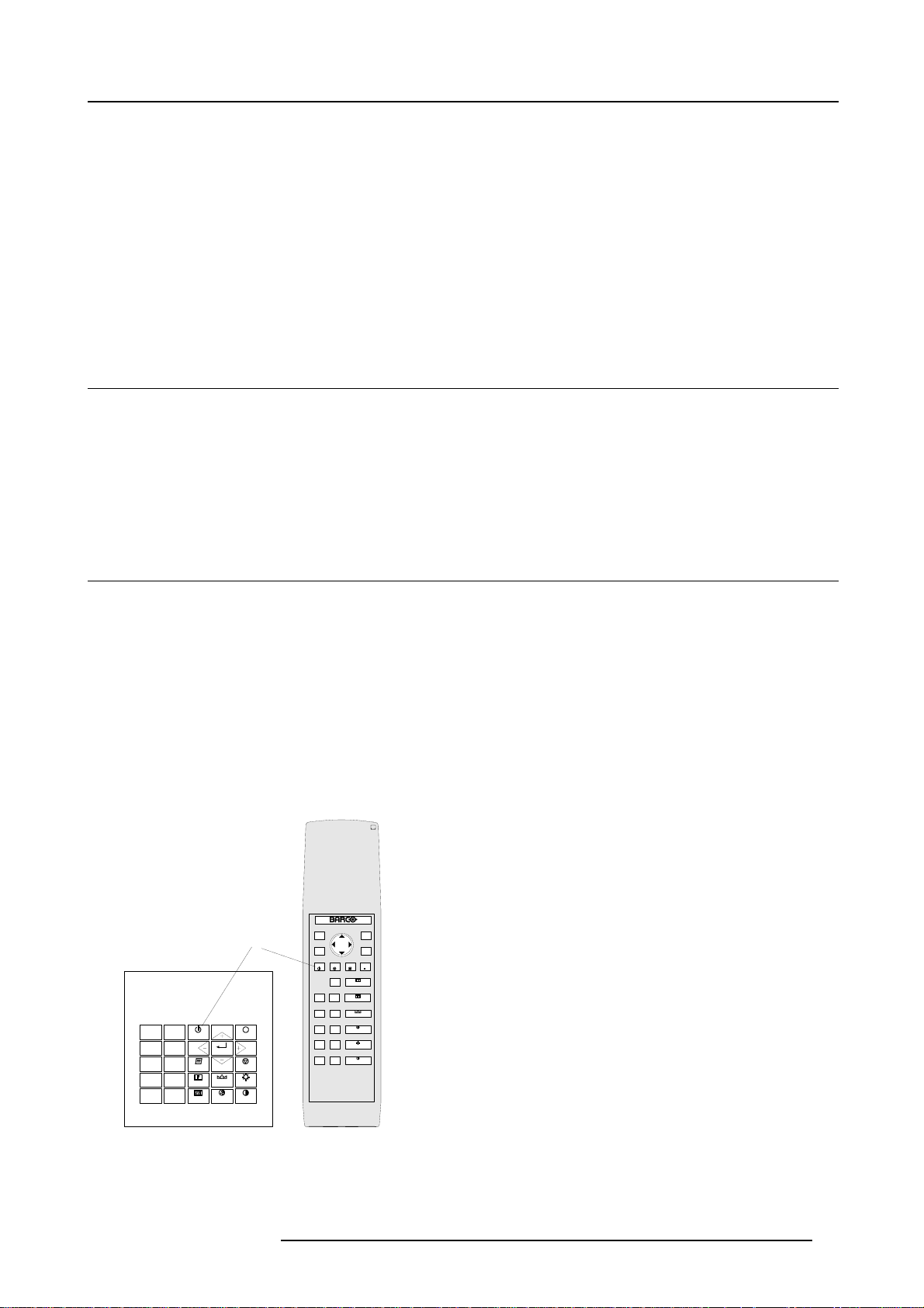
5.1 RCU & Local keypad
How controlling the projector ?
The projector can be controlled by the local keypad or by the remote control unit.
Location of the local keypad ?
The local keypad is located on the input side of the projector.
Remote control functions.
This remote control includes a battery powered infrared (IR) transmitter that allows the user to control the projector remotely. This
remote control is used for source selection, control, adaptation and set up. It includes automatic storing of picture controls (Brightness, Sharpness...) and settings.
Other functions of the remote control are :
• switching between stand by and operational mode.
• switching to "pause" (blanked picture, full power for immediate restarting)
• direct access to all connected sources.
5.2 Terminology overview
Overview
The following table gives an overview of the different functionalities o
4
14
0
9
7
5
3
1
STANDBY
8
6
TEXT
4
SHARPN
2
PHASE
ENTER
TINT
COLOR
EXIT
PAUSE
BRIGHTN
CONTRAST
13
12
5
10
8
9
f the keys.
15
1
TEXT
-
PHASE
-
SHARPNESS
-
TINT
-
COLOR
-
BRIGHTNESS
-
CONTRAST
EXIT
ENTER
FREEZ
2
ADJ
3
STBY
4
5
6
7
PAUSE
HELP
?
0
9
7
8
6
5
4
3
21
14
13
12
11
10
+
9
+
+
+
+
+
8
Image 5-1
Local keypad & RCU
7
32a
R5976654 SLM R12+ 09022004 35
Page 40

5. Getting Started
1 Barco key selection key, to get direct access to the lens adjustment menus.
2 ADJ
3 Address key
4
STDY
5
PAU SE to stop projection for a short time, press ’PAUSE’. The image disappears but full power
6 Help
7
Digit buttons direct input selection
8 Picture controls use these buttons to obtain the desired picture analog level.
9
PHASE used to remove the instability of the image.
10 TEXT
11 FREEZ
12 ENTER
13 EXIT to leave the adjustment mode or to scroll upwards when in the adjustment mode.
ADJUST key, to enter or exit the adjustment mode.
(recessed key), to enter the address of the projector (between 0 and 9). Press the
recessed address key with a pencil, followed by pressing one digit button between
0and9.
stand-by button, to start projector when the power switch is switched on and to switch
off the projector without switching off the power switch.
is retained for immediate restarting.
n line help information (not yet available)
when adjusting one of the image, e.g. controls during a meeting, the displayed bar
scale can be removed by pressing ’TEXT’ key first. To re-display the bar scale on the
screen, press ’TEXT’ key again. When TEXT is ’off’, no adjustment menu’s will be
displayed on the screen when entering the adjustment mode.
press to freeze the projected image.
to start up the adjustment mode or to confirm an adjustment or selection in the
adjustment mode.
14
Cursor keys (on RCU) or ’+’ and ’-’ keys (cursor keys) on the local keypad : to make menu selections
15
RC Operating indication lights up when a button on the remote control is pressed. (This is a visual indicat
Table 5-1
5.3 Operating the projector
5.3.1 Switching on
How to switch on.
1. Press the power switch to switch on the projector.
- When ’0’ is visible, the projector is switched off.
- When ’1’ is visible, the projector is switched on.
The projector starts i standby mode.
when in the adjustment mode or to zoom/focus when the direct access is active.
Comparison between the cursor keys and the use of the ’+’ and ’-’ keys on the local
keypad : RCU = local keypad
cursor key up = ’+’ key up
cursor key down = ’-’ key down
cursor key right = ’+’ key right
cursor key left = ’-’ key left
Use the ’+’ and ’-’ keys (cursor keys) : to increase or decrease the analog level of the
image controls when they are first selected.
or to
check the operation of the remote control)
Starting image projection.
1. Press Stand by key once on the local keypad or on the remote control.
The projector mode indication lamp will be green (image 5-2)
Or,
Press a digit button to select an input source.
36
R5976654 SLM R12+ 09022004
Page 41

EXIT
A
0
9
STANDBY
7
8
6
5
TEXT
3
4
SHARPN
2
1
PHASE
ENTER
TINT
COLOR
EXIT
PAUSE
BRIGHTN
CONTRAST
ADJ
ENTER
FREEZTEXT
STBY
PAUSE
-
HELP
+
PHASE
?
-
+
0
SHARPNESS
9
-
+
7
TINT
8
-
+
6
5
COLOR
-
+
4
3
BRIGHTNESS
-
+
21
CONTRAST
32a
Image 5-2
Lamp Run time indication
see chapter "4. Connections", "Switching on", page 23
Lamp Light output indication
see chapter "4. Connections", "Switching on", page 23
5. Getting Started
Lamp Z-axis indication
see chapter "4. Connections", "Switching on", page 23
5.3.2 Switching to standby
Howtoswitchtostandby?
1. Press Standby to switch the projector to standby.
Switching to Standby. When the projector is running and you want to go to standby, press the standby key for
2 seconds until the message ’Saving data, please wait’ is displayed. Do not press any longer on the standby
key otherwise the projector will restart.
5.3.3 Switching off
How to switch off the projector?
1. Press first Standby.
2. Let cool down the projector until the fans stop blowing, at least 15 min.
3. Switch off the projector with the power switch.
5.3.4 Temperature error DMD
Overview
When the temperature of one of the DMD is too lo
switching to standby, the following message appears for 3 seconds on the screen : ’DMD out of operating temperature range.
Automatic shutdown is activated.’.
A ’-t’ appears on the LED display to indicate the user that the projector is switched to standby due to DMD temperature problems.
Operating temperature range of the DMD :
+10°C and +35°C.
w or too high the projector will be switched automatically to standby. Before
R5976654 SLM R12+ 09022004
37
Page 42

5. Getting Started
ERROR
DMD out of operating
temperature
range
Automatic shutdown is
activated
Menu 5-1
5.4 Quick Set Up Adjustments
Overview
• Quick Language Change
• Quick Lens Adjustment
• Quick On Screen Color change
5.4.1 Quick Language Change
What can be done?
Only if different on screen languages are available, these can be changed in quick way by following the next procedure.
How to change
1. Press ENTER to start up the adjustment mode.
2. Press the cursor key ↑ or ↓ to highlight Service. (menu 5-2)
When password protected, your password will be asked. (more explanation about access by password can be found in Chapter
’Start up the Adjustment mode’.
3. Press ENTER to display the Service mode menu.
4. Push the cursor key ↑ or ↓ to highlight Change Language . If not visible in the menu, highlight first More and press ENTER to
display a second service menu. Select then Change Language. (menu 5-3)
5. Press ENTER to display the language selection menu.
6. Push the cursor key ↑ or ↓ to highlight the desired language. (menu 5-4)
Note: For the moment, only E n glish is available.
ADJUSTMENT MODE
Select a path from below :
RANDOM ACCESS
INSTALLATION
SERVICE
Select with ↑ or ↓
then <ENTER>
<EXIT> to return
Menu 5-2
Menu 5-3
SERVICE
IDENTIFICATION
CHANGE PASSWORD
CHANGE LANGUAGE
CHANGE PROJ. ADDRESS
SERIAL COMMUNICATION
NETWORK
LAMP
DIMMING
MORE...
Select with ↑ or ↓
then <ENTER>
<EXIT> to return
Menu 5-4
CHANGE LANGUAGE
ENGLISH
Select with ↑ or ↓
then <ENTER>
<EXIT> to return
5.4.2 Quick Lens Adjustment
Quick zoom/focus adjustment
1. Press the Selection key *, Barco key.
Thezoom/focusmenuwillbedisplayed. (image5-3)
2. Push the cursor key ↑ or ↓ to zoom and ← or → to focus the image.
3. When finished, press EXIT key to return or ENTER to continue to the shift adjustment.
38
R5976654 SLM R12+ 09022004
Page 43

LENS ADJUSTMENT ZOOM/FOCUS
ZOOM with or ,
FOCUS with or
<ENTER> to shift
<EXIT> to return
Image 5-3
Quick shift adjustment
1. Press the Selection key *, Barco key.
The zoom/focus menu will be displayed (image 5-3).
2. Press ENTER.
The shift menu will be displayed. (image 5-4)
3. Push the cursor key ↑ or ↓ to shift the image up or down and ← or → to shift the image left or right.
4. When finished, press EXIT key to return or ENTER to continue to zoom/focus.
5. Getting Started
LENS ADJUSTMENT SHIFT
SHIFT with or , or
<ENTER> to zoom/focus
<EXIT> to return
Image 5-4
5.4.3 Quick On Screen Color change
What can be done ?
For quick change of the on-screen color of the highlighted
The highlighted items on the menus can be displayed in red, green or yellow.
items.
How to change ?
1. Press ENTER to start up the adjustment mode.
2. Push the cursor key ↑ or ↓ to highlight Installation. (menu 5-5)
3. Press ENTER to select.
4. Push the cursor key ↑ or ↓ to highlight OSD . (menu 5-6)
5. Press ENTER to select.
The OSD menu will be displayed. (menu 5-7)
6. Push the cursor key ↑ or ↓ to highlight Highlighted item color.
7. Press ENTER to toggle between red, green and yellow.
ADJUSTMENT MODE
Select a path from below :
RANDOM ACCESS
INSTALLATION
SERVICE
Select with ↑ or ↓
then <ENTER>
<EXIT> to return
Menu 5-5
Menu 5-6
INSTALLATION
INPUT SLOTS
800 PERIPHERAL
SOURCE SWITCHING
NO SIGNAL
CONTRAST ENHANCEMENT
CONVERGENCE
CONFIGURATION
LENS
QUICK ACCESS KEYS
OSD
INTERNAL PATTERNS
Select with ↑ or ↓
then <ENTER>
<EXIT> to return
OSD
HIGHLIGHT ITEM COLOR [red]
MENU POSITION [Default]
Select with ↑ or ↓
then <ENTER>
<EXIT> to return
Menu 5-7
R5976654 SLM R12+ 09022004 39
Page 44

5. Getting Started
5.5 Using the RCU
Pointing to the reflective screen
1. Point the front of the RCU to the reflective screen surface. (image 5-5)
Ceiling
IR sensor
Screen
RCU
Image 5-5
Hardwired Remote Input
1. Plug one end of the remote cable in the connector on the bottom of the RCU.
2. Plug the other end in the connector in the front panel of the projector labelled RC. (image 5-6)
IR-ReceiverDiagnostic Code
COMM PORT 10/(100) BASE-T
OUTIN
R9840450
HD SDI DIGITAL MODULE
DVI OUTPUT
Two way
Hardwired
hardwired
remote
remote
CTRL 2
CTRL 3
On
R
On
Hardwired
remote
CTRL 1
OUT IN
SDI DIGITAL INPUT
GB
H/C V
High Bandwidth 5 CABLE INPUT
R
GB
H/C V
High Bandwidth 5 CABLE INPUT
Green Operation
Red Stand-by
RS232/422 IN
IRSync OK
RS232/422 OUT
On
9840110
On
DVI INPUT
OnOn
DVI INPUT
RCU
Image 5-6
40 R5976654 SLM R12+ 09022004
Page 45

5. Getting Started
Hardwired to the XLR input
1. Plug one end of the remote cable in the connector on the bottom of the RCU
2. Plug the other end in the connector in the front panel of the projector labelled Hardwired CTRL2. (image 5-7)
Two way
Hardwired
hardwired
remote
remote
CTRL 2
CTRL 3
On
R
On
Hardwired
remote
CTRL 1
OUT IN
SDI DIGITAL INPUT
GB
H/C V
High Bandwidth 5 CABLE INPUT
R
GB
H/C V
High Bandwidth 5 CABLE INPUT
Green Operation
Red Stand-by
IRSync OK
RS232/422 IN
9840110
On
OnOn
Pins XLR plug
1 Ground
2 Signal
3 Ground
RS232/422 OUT
On
DVI INPUT
DVI INPUT
IR-ReceiverDiagnostic Code
COMM PORT 10/(100)BASE-T
OUTIN
R9840450
HD SDI DIGITAL MODULE
DVI OUTPUT
RCU
Image 5-7
Directly to one of the IR sensors
When using the wireless remote control, make sure you are within the effective operating distance (30m, 100ft in a straight line). The
remote control unit will not function properly if strong light strikes the sensor window or if there are obstacles between the remote
control unit and the projector IR sensor.
R5976654 SLM R12+ 09022004
41
Page 46

5. Getting Started
Image 5-8
IR sensor
Front of projector
45ø 45ø
ADJ EXIT
ADDR
ENTER
STBY MUTE TEXT
FREEZ
-
+
SHARPNESS
0
9
+
TINT
7
8
-
+
COLOR
65
-
+
RCU
BRIGHTNESS
4
3
+
CONTRAST
21
Table
IR sensor
Rear of projector
45ø 45ø
ADJ EXIT
ADDR
ENTER
STBY MUTE TEXT
FREEZ
-
+
SHARPNESS
0
9
+
TINT
7
8
-
+
COLOR
65
-
+
RCU
BRIGHTNESS
43
+
CONTRAST
21
Side of projector
45ø 45ø
ADJ EXIT
ADDR
ENTER
MUTE TEXT
STBY
FREEZ
-
+
SHARPNESS
0
9
+
TINT
7
8
-
+
COLOR
65
-
+
RCU
BRIGHTNESS
43
+
CONTRAST
21
5.6 Projector Address
5.6.1 Controlling the projector
Projector address
Address installed in the projector to be individually controlled.
Common address
Default address. Projector will always execute the command coming from a RCU programmed with that common
address.
Why a projector address ?
As more than one projector can be installed in a room, the separate projector should be separately addressable with an RCU or
computer. There for each projector has its o
Set up an individual Projector Address.
The set up of a projector address can be done via the software. See ’Change projector address’ in chapter ’Service mode’.
Projector controlling.
Every projector requires an individual address between 0 and 255 which can be set in the Service mode.
Whentheaddressisset,theprojectorcanbecontrollednow:
• RCU for addresses between 0 and 9.
• computer, e.g. IBM PC (or compatible), Apple MAC, etc. for addresses between 0 and 255.
wn address.
Common Address
Every projector has a common address ’0’ or ’1’. The choice between ’0’ and ’1’ can be selected in the Service mode.
42
R5976654 SLM R12+ 09022004
Page 47

5.6.2 Displaying and Programming addresses
Displaying the Projector Address on the Screen.
1. Press Address key (recessed key on the RCU) with a pencil.
The projector’s address will be displayed in a ’Text box’
To continue using the RCU with that specific address, it is necessary to enter the same address with the
digit buttons (address between 0 and 9) within 5 seconds after pushing the address key. For example : if the
Address key displays projector address 003, then press "3" digit button on the RCU to set the RCU’s address
to match the projector’s address. Do not press 003 digits. This will address the remote control to ’0’ and
control all projectors in the room. If the address is not entered within 5 seconds, the RCU returns to its default
address (zero address) and control all projectors in the room.
How to Program an Address into the RCU?
1. Press the Address key (recessed key on the RCU) with a pencil.
2. Enter the address with the digit buttons within 5 seconds after pushing the address key.
Note: That address can be any digit between 0 and 9.
5.7 Controlling the Projector
Input Selection
Key in the corresponding slot number with the digit keys on the RCU. The selected source will be displayed.
5. Getting Started
Picture Controls
When an image control is pressed, a text box with a bar scale, icon and function name of the control, e.g. ’brightness...’ appears on
the screen (only if text is ON). See example screen. The length of the bar scale and the value of the numeric indication indicate the
current memorized setting for this source. The bar scale changes as the control stick on the RCU is pressed or the + or - buttons
on the local keypad.
Brightness
Contrast A correct ’contrast’ setting is important for good image reproduction. Adjust the contrast to the level
Color Color saturation is only active for Video and S-Video. Adjust the color intensity of the picture.
Tint
Sharpness
Phase Use the arrow buttons to adjust the phase.
A correct ’brightness’ setting is important for good image reproduction.
Use the + button for a higher brightness.
Use the - button for a lower brightness.
you prefer, according to room lighting conditions.
Use the + button for a higher contrast.
Use the - button for lower contrast.
Use the + button for richer colors.
Use the - button for lighter colors.
Tint is only active for Video and S-Video when using the NTSC 4.43 or NTSC 3.58 system.
Use the + button
Use the - button.
no sharpness available
The Pause Key
When the Pause key is pressed, the image projection is stopped, a black screen will be displayed and the projector remains with full
power for immediate restart. The sound is not interrupted. The display on front of the projector will show a "P".
To restart the image :
•PressPause key.
•PressEXIT key
• Select a source number.
R5976654 SLM R12+ 09022004
43
Page 48

5. Getting Started
The Stand-by Key
When the Stand-by key is pressed, the image projection is stopped and the projector goes to stand-by. This situation is used when
a projection stop is planned for a longer period.
44
R5976654 SLM R12+ 09022004
Page 49

6. Start up of the Adjustment mode
6. STARTUPOFTHEADJUSTMENTMODE
6.1 Start up
Possible paths
There are 3 possible paths to follow once in the Adjustment mode. They are :
• Installation - Installation should be selected if a new input module is installed or a new source is connected to an existing input
module. Also when the projector is relocated in a new configuration.
• Random Access - Random Access should be selected to set up a new source.
• Service - Service should be selected if the user intends to change general settings such as password, language, address, etc.or
some service actions or get set-up information.
How to start up.
1. Press ADJUST or ENTER to enter the Adjustment mode.
The adjustment mode opens. (menu 6-1)
2. The cursor key (RCU) or ’+ or ’-’ keys (local keypad) are used to make menu selections and also for adjustments.
3. The ENTER and EXIT keys are used to move forward and backward through the menu structure.
4. The ADJUST key can be used to terminate the adjustment mode while any path selection menu is displayed.
ADJUSTMENT MODE
Select a path from below :
RANDOM ACCESS
INSTALLATION
SERVICE
Select with ↑ or ↓
then <ENTER>
<EXIT> to return
Menu 6-1
6.2 Password
Password protection of some items.
Some items in the Adjustment mode are password protected. While selecting such an item, the projector asks to enter your password
(Password protection is only available when the passwor
change the position of the password strap).
d strap on the controller module is ON, call an authorized service center to
R5976654 SLM R12+ 09022004
45
Page 50

6. Start up of the Adjustment mode
Entering your password
1. The first digit position is highlighted. Enter the first digit. (menu 6-2)
The highlighted square jumps to the next position.
2. Continue with the other digits
Example: 2319
When your password is correct, you gain access to the selected item.
When your password is wrong. The error message Invalid password is displayed on the screen. Press EXIT to continue and to
return to the adjustment menu.
PASSWORD
ENTER PASSWORD
----
Use numeric keys
<EXIT> to return
Menu 6-2
Factoryprogrammedpassword:0000
Password remark
When re-entering the Adjustment mode, it will be necessary to enter the password again
when selecting a password protected item.
Changing your password
To change your password, see chapter Service Mode, Change Password.
6.3 Menus on Local LCD Display
Overview
When text is ’off’, no menus will be displayed on the projection screen. But
through the menus. The menus will be displayed line by line in the same order as they were displayed on the projection screen.
Adjustments can be done while the projector is running without projecting the disturbing menus on the screen.
Use the cursor keys to scroll through the menus and press ENTER to activate the displayed menu.
on the local LCD display, it is still possible to scroll
46
R5976654 SLM R12+ 09022004
Page 51

7. Random Access Adjustment Mode
7. RANDOM ACCESS ADJUSTMENT MODE
Overview
• Overview Flow
•PictureServices
• Picture Tuning
• Geometry
• ScenergiX
• Picture in Picture (PiP)
• Save Changes
7.1 Overview Flow
Overview
LOAD
EDIT
FILE SERVICE
RENAME
COPY
DELETE
OPTIONS
RANDOM ACCES
ADJUSTMENT MODE
Image 7-1
PICTURE TUNING
GEOMETRY
SCENERGIX
PIP
SAVE CHANGES
COLOR TEMPERATURE
GAMMA
COLOR SPACE
NOISE REDUCTION
INPUT BALANCE
SHIFT
SIZE
SIDE KEYSTONE
BLANKING
ASPECT RATIO
OPTIONS
R5976654 SLM R12+ 09022004 47
Page 52

7. Random Access Adjustment Mode
Start up
1. Push the cursor key ↑ or ↓ to highlight Random Access. (menu 7-1)
2. Press ENTER. (menu 7-2)
ADJUSTMENT MODE
Select a path from below :
RANDOM ACCESS
INSTALLATION
SERVICE
Select with ↑ or ↓
then <ENTER>
<EXIT> to return
Menu 7-1
Menu 7-2
RANDOM ACCESS
ADJUSTMENT MODE
FILE SERVICE
PICTURE TUNING
GEOMETRY
SCENERGIX
PIP
SAVE CHANGES
Select with ↑ or ↓
then <ENTER>
<EXIT> to return
7.2 Picture Services
7.2.1 File annotation
How a file is built up
The file notation on a menu is built up in different parts. Let us have a look to these parts.
Take the following notation : xxxxxxxx.eee n ppppXppppi
xxxxxxxx
eee
n
base name, 8 characters
file extension
first character C : custom made file
first character S : standard file
The second and third character is used for a following number (= file
index). The file index for custom files : 00 to 63.
source number
ppppXpppp active pixel rating
i i or blank
i = interlaced file
blank = not interlaced
Table 7-1
7.2.2 Possible file manipulations
Connecting a new source.
Before using a new source, a correct file has to be installed. The projector’s memory contains a list of files corresponding to the most
used sources. When the new source corresponds with one of these files, the file can be loaded and saved for future use. When
there is a little dif
ference, the file can also be loaded and then edited until the source specs are reached.
file loading can be d
one automatically (see "File Options", page 56). Files with a ~ in front of the file name are
temporary files. These files will be deleted when switching to another source.
48 R5976654 SLM R12+ 09022004
Page 53

Possible file Manipulations
The following file manipulations are possible :
• Load : installation of a file for a new source.
• Edit : editing a loaded file to the source specs.
• Rename : renaming a file.
• Copy : copying a file.
• Delete : deleting a file
• Options : way of sorting the files.
7.2.3 Start up
Start up
To enter the File Service, handle as follow :
1. Push the cursor key ↑ or ↓ to highlight File Service. (menu 7-3)
2. Press ENTER to select.
The File Service menu will be displayed. (menu 7-4)
7. Random Access Adjustment Mode
Menu 7-3
RANDOM ACCESS
ADJUSTMENT MODE
FILE SERVICE
PICTURE TUNING
GEOMETRY
SCENERGIX
PIP
SAVE CHANGES
Select with ↑ or ↓
then <ENTER>
<EXIT> to return
Menu 7-4
FILE SERVICE
Select with ↑ or ↓
then <ENTER>
<EXIT> to return
7.2.4 Load file
StartupLoadfile
To start up the load file, handle as follow :
1. Push the cursor key ↑ or ↓ to highlight Load. (menu 7-5)
2. Press ENTER to select.
The Load menu displays the corresponding files depending on the installed filter. (menu 7-6)
FILE SERVICE
LOAD
EDIT
RENAME
COPY
DELETE
OPTIONS
F
video525.s01 1 675x240i
video525.c01 1 675x240i
video525.c02 1 675x240i
---------------------------Active file : Video525.c50
LOAD FILE
FILTER LIST [All]
ilename Src resolution
LOAD
EDIT
RENAME
COPY
DELETE
OPTIONS
Select with ↑ or ↓ , →
<ENTER> to accept
<EXIT> to return
Menu 7-6
Menu 7-5
Select with ↑ or ↓
then <ENTER>
<EXIT> to return
Changing the filter setting
1. Push the cursor key ↑ or ↓ highlight filter list.
2. Press ENTER to toggle the annotation between brackets.
[All] : all files that can be loaded will be displayed.
[Fit] : only the best fitting files will be displayed (with a distinction of ± 2 lines and line duration of ± 300 ns, if nothing is found
within this small area, the projector continues searching until it finds something).
R5976654 SLM R12+ 09022004
49
Page 54

7. Random Access Adjustment Mode
Howtoloadafile?
1. Push the cursor key ↑ or ↓ to select the best fitting file. (menu 7-7)
2. Press ENTER to select.
A confirm Load file menu will be displayed with the newly created file and the one on which the new file is based on. (menu 7-8)
3. Press ENTER to confirm the new creation or EXIT to return to the load file menu.
LOAD FILE
FILTER LIST [All]
ilename Src resolution
F
video525.s01 1 675x240i
video525.c01 1 675x240i
video525.c02 1 675x240i
---------------------------Active file : Video525.c50
Select with ↑ or ↓ , →
<ENTER> to accept
<EXIT> to return
Menu 7-7
Menu 7-8
CONFIRM
LOAD FILE
create file
Video525.c02
based on file
Video525.s01?
<ENTER> to return
<EXIT> to return
During a load file, the actual file is displayed next to the indication Active file.
When scrolling through the files, the image will be adapted according to the settings of the selected file ( on
line adaptation.
The image is not perfect ?
If the displayed image is not correct after selecting the best fitting file, go to the Edit menu, select the active file and change the File
settings.
7.2.5 Edit File
7.2.5.1 Start up
How to start up the Edit menu ?
To start up the EDIT menu :
1. Push the cursor key ↑ or ↓ to highlight Edit. (menu 7-9)
2. Press ENTER to select.
The Edit file adaptation menu will be displayed. (menu 7-10)
3. Select the file which must be edited (mostly the active file).
4. Press ENTER.
The file name will be displayed in the upper right corner. (menu 7-11)
Menu 7-9
FILE SERVICE
LOAD
EDIT
RENAME
COPY
DELETE
OPTIONS
Select with ↑ or ↓
then <ENTER>
<EXIT> to return
F
video525.s01 1 675x240i
video525.c01 1 675x240i
video525.c02 1 675x240i
------------------------------Active file : Video525.c50
Menu 7-10
EDIT FILE
ilename Src resolution
Select with ↑ or ↓ , →
<ENTER> to accept
<EXIT> to return
EDIT FILE xga.s30
HORIZONTAL
TOTAL 1344 PIXELS
ACTIVE 1024 PIXELS
START 296 PIXELS
PERIOD 20.678 µs
VERTICAL (FIELD)
TOTAL 806 LINES
ACTIVE 768 LINES
START 36 LINES
INTERLACED [OFF]
READ AMDS
OPTIONS
↑ , ↓ , ← , → <ENTER>, <EXIT>
Menu 7-11
50 R5976654 SLM R12+ 09022004
Page 55

7.2.5.2 Changing the settings
Different methods
The 3 different methods to change a setting will be describe hereafter. These methods are:
• with the numeric keys on the remote control.
• with the arrow keys selecting the changing digit.
• with the arrow keys counting up or down.
How to change a setting with the numeric keys?
1. Push the cursor key ↑ or ↓ to highlight an item.
The color of the selected item will change.
2. Press ENTER to activate the digits.
3. Enter directly with the numeric keys on the RCU or local keypad the new value.
How to change a setting with the cursor keys?
1. Push the cursor key ↑ or ↓ to highlight an item.
The color of the selected item will change.
2. Press ENTER to activate the digits.
3. Push the cursor key ← or → to select the changing digit.
4. Push the cursor key ↑ or ↓ to scroll to the desired digit.
5. When finished, press ENTER to confirm.
7. Random Access Adjustment Mode
How to change a setting with the cursor keys and counting up or down?
1. Push the cursor key ↑ or ↓ to highlight an item.
The color of the selected item will change.
2. Press ENTER to activate.
3. Counting up or down by pushing the cursor key ← or →.
7.2.5.3 Correct value
What is already available during start up?
During the installation of a file with LOAD, the horizontal period, the total number of vertical lines and the interlaced mode are
automatically measured and filled in in the menu table. These values will be available when starting up the EDIT procedure of an
active file.
Do not adjust these settings on an active file, they are used to identify the input source file.
How to find the correct values for the item in the Edit file menu?
Horizontal Total Pixels
If the value for "Horizontal Total Pixels" is wrong, sampling mistakes (small vertical bars in the
projected image) will be seen in the image.
Select "Total" and adjust the pixel quantity. Adjust for zero bars
hint: if the number of bars increase, adjust in the other direction.
.
Active Pixels
Horizontal Start number of pixels between the beginning of the input signal and the start of the video information in
Horizontal Period
Vertical Total Lines
Active Lines
R5976654 SLM R12+ 09022004 51
The "Active Pixels" : determine the width of the window on the screen. This value is normally given in
the source specifications. If not, adjust until full image is displayed (no missing pixels).
the signal.
already filled in with the correct value when active file.
already filled when an active file is selected to be edited
number of horizontal lines determining the height of the projected image. This value is normally given
in the specification of the source. If not, adjust until full image height is displayed (no missing lines)
Page 56

7. Random Access Adjustment Mode
Vertical Start number of lines between the start of the input signal and start of the image on the screen.
Interlaced [On] or [Off] this selection is automatically filled when active file has to be edited. If the image is wrong due to
mismeasurement, use the ENTER key to toggle between [On] and [Off]. (for interlaced images,
1 frame contains 2 fields).
Read AMDS AMDS = automatic mode detection & synchronization
During the installation of a file with LOAD, the system automatically measured the horizontal period,
the total vertical lines and the interlaced mode. When selecting Read AMDS, the system remeasures
the above indicated items.
How to install the correct settings for the options in the Edit file menu.
EDIT FILE OPTIONS
Source number 1
Clamp position [leading]
Clamp delay 0
Clamp width 10
Field polarity [pos]
Field select [both]
Vertical refresh [sync]
Film Mode Detection [on]
Banner Protect [on]
Select with ↑ or ↓
<ENTER> to toggle
↑ or ↓ to change value
<EXIT> to return
Menu 7-12
Source number The source number of a non-active
possible to create a file for future source numbers.
Clamp position Clamping determines the black level of the signal. The clamp pulse can be related to the leading or
the trailing edge of the sync pu
Clamp delay The time between the leading edge of the clamp pulse and the locked edge of the sync pulse. Can be
any value between 0 and 255. Change the value by pushing the cursor key ↑ or ↓.
file can be changed to any other source number. This makes it
lse. Use the ENTER key to toggle between [leading] and [trailing].
Clamp width The width of the clamp pulse c
the cursor key ↑ or ↓.
Leading edge
Trailinging edge
Sync
pulse
Clamp
pulse
Clamp
Clamp
delay
width
Image 7-2
for Clamp position [trailing]
Example
Field polarity
The field polarity function is used for interlaced images. Both rasters of the image could be shifted in a
wrong way (double lines are visible in the image). This can be corrected by forcing the field polarity to
[neg] or [pos]. Use the ENTER key to toggle between [pos] and [neg].
Field select
Default [both]
The field select is only used for interlaced images. One frame of an interlaced image contains two
, an even and an odd field. The choice exists to project [both] fields on the screen or only the
fields
[even] or [odd] field. This can be useful for 3D projection. Use the ENTER key to toggle between
[both], [even] and [odd].
an be any value between 0 and 255. Change the value by pushing
52 R5976654 SLM R12+ 09022004
Page 57

7. Random Access Adjustment Mode
Vertical refresh
[sync/async]
Film mode detection:
[On] or [Off]
Banner Protect: [On]
or [Off]
The way of updating the image information. Not available for PAL-NTSC-SECAM sources. This
option will be displayed in gray.
• For sources with a vertical frequency up to 60 Hz : the vertical refresh rate is the same as the
vertical frequency of the incoming source. This is a necessity to project moving images without
’motion artifacts’. For stationary images with a vertical frequency up to 60 Hz it is still possible
to use asynchronous refresh. When loading Pal, Secam, NTSC-files the synchronous mode is
default, for all other sources below 60 Hz asynchronous mode is default.
• For sources with a vertical frequency higher that 60 Hz : the vertical refresh is different than the
vertical frequency of the incoming source. Synchronous refresh cannot be used.
Detects in the [on] mode if the source is film or video. Use the ENTER key to toggle between [on] or [off]
When enabled, the hardware looks for tell-tale signs of 3:2 or 2:2 pull-down sequences. These are the
result of converting cinema material recorded at 24 frames-per-second to the television frequencies of
60 or 50 interlaced fields per second respectively. When FILM conversion is detected, the original
24 frames-per-second are restored. This avoids deinterlacing artefacts, and results in a perfect
artefact-free display. Note that in some cases (video clips, scrolling newstickers,...) FILM and VIDEO
material are mixed on one screen. This may confuse the detector and cause it to go into FILM
restoration mode. This will cause "jaggies" or motion artefacts. In such cases, disabling FILM mode
processing is the best cure.
Only active when film mode detection is in the on position. Use the ENTER key to toggle between
[on] or [off].
FILM mode processing normally processes the entire display, but this may cause problems on sources
where video and FILM content are mixed. One very common example is scrolling banners at the
bottom of the screen (e.g. financial news). For those cases, the "banner protect" feature will force the
bottom quarter of the screen to be always processed in VIDEO mode, regardless of the rest of the
screen, which may be either video or FILM mode.
3:2 pull-down
Method used to map the 24 fps of film onto the 30 fps (60 fields) or 25 fps (50 fields), so that one film frame occupies
three video fields, the next two, etc. It means the two fields of every other video frame come from different film frames
making operations such as rotoscoping impossible, and requiring care in editing. Some sophisticated equipment can
unravel the 3:2 sequence to allow frame-by-frame treatment and subsequently re-compose 3:2. The 3:2 sequence
repeats every five video frames and four film frames, the latter identified as A-D. Only film frame A is fully on a video
frame and so exists at one time code only, making it the editable point of the video sequence.
2:2 pull-down
The process
video fields. ( AD )
Artefacts
Undesirable elements or defects in a video picture. These may occur naturally in the video process and must be
eliminated in order to achieve a high-quality picture. Most common in analog are cross color and cross luminance.
Most common in digital are macroblocks, which resemble pixelation of the video image.
of transferring 24-frames/sec film format into video by repeating each frame (used for PAL DVD’s) as two
R5976654 SLM R12+ 09022004 53
Page 58

7. Random Access Adjustment Mode
7.2.6 Rename
Start Up
To change the name of a selected file :
1. Push the cursor key ↑ or ↓ to highlight Rename. (menu 7-13)
2. Press ENTER.
The Rename selection menu will be displayed. (menu 7-14)
3. Push the cursor key ↑ or ↓ to select a file name.
4. Press ENTER to select.
The Rename file menu will be displayed with the selected file name already filled in, in the ’From file name :’ area and in the ’To
file name :’ area. The first character in the ’To file name :’ area is highlighted. (menu 7-15)
Menu 7-13
FILE SERVICE
LOAD
EDIT
RENAME
COPY
DELETE
OPTIONS
Select with ↑ or ↓
then <ENTER>
<EXIT> to return
Menu 7-14
RENAME FILE
F
ilename Src resolution
video525.s01 1 675x240i
video525.c01 1 675x240i
video525.c02 1 675x240i
------------------------------Active file : Video525.c50
Select with ↑ or ↓ , →
<ENTER> to accept
<EXIT> to return
From file name :
Video525.c01
To file name :
Select with ← or →
Reprogram with ↑ or ↓
or numeric keys
<ENTER> to confirm
<EXIT> to return
Menu 7-15
RENAME FILE
demo.c10
Changing the characters
1. Push the cursor keys ← or → to select the desired character. (menu 7-16)
Or,
Change that character by pushing the cursor keys ↑ or ↓. Numeric characters can be ent
RCU.
Or,
Press ENTER to confirm.
The renamed file is entered in the list of files.
2. Press EXIT to return to the Rename menu selection.
No changes are made.
RENAME FILE
From file name :
Video525.c01
To file name :
demo.c10
ered directly with numeric keys on the
Select with ← or →
Reprogram with ↑ or ↓
or numeric keys
<ENTER> to confirm
<EXIT> to return
Menu 7-16
54 R5976654 SLM R12+ 09022004
Page 59

7.2.7 Copy
Start Up
To copy the name of a selected file :
1. Push the cursor key ↑ or ↓ to highlight Copy.
2. Press ENTER.
The Copy selection menu will be displayed. (menu 7-17)
3. Push the cursor key ↑ or ↓ to select a file name.
4. Press ENTER to select.
The Copy file menu will be displayed with the selected file name already filled in, in the ’From file name :’ area and in the ’To file
name :’ area. The first character in the ’To file name :’ area is highlighted. (menu 7-18)
7. Random Access Adjustment Mode
COPY FILE
F
ilename Src resolution
video525.s01 1 675x240i
video525.c01 1 675x240i
video525.c02 1 675x240i
------------------------------Active file : Video525.c50
Select with ↑ or ↓ , →
<ENTER> to accept
<EXIT> to return
Menu 7-17
Menu 7-18
COPY FILE
Frome file name :
Video525.s01
To file name :
demo.c10
Select with ← or →
Reprogram with ↑ or ↓
or numeric keys
<ENTER> to confirm
<EXIT> to return
Changing the characters
1. Push the cursor keys ← or → to select the desired character. (menu 7-19)
Or,
Change that character by pushing the cursor keys ↑ or ↓. Numeric characters can be ent
RCU.
Or,
Press ENTER to confirm.
The copy file is entered in the list of files.
2. Press EXIT to return to the Copy menu selection.
No changes are made.
COPY FILE
Frome file name :
Video525.s01
To file name :
demo.c10
ered directly with numeric keys on the
Select with ← or →
Reprogram with ↑ or ↓
or numeric keys
<ENTER> to confirm
<EXIT> to return
Menu 7-19
7.2.8 Delete
Start up and delete
To delete a selected file out of the list of files :
1. Push the cursor key ↑ or ↓ to highlight Delete. (menu 7-20)
2. Press ENTER.
The delete selection menu will be displayed. (menu 7-21)
3. Push the cursor key ↑ or ↓ to select a file name.
R5976654 SLM R12+ 09022004
55
Page 60

7. Random Access Adjustment Mode
4. Press ENTER to select.
If [all] is selected, your password has to be entered before all files will be deleted.
A confirmation menu "Delete file ’file name’?" is displayed. (menu 7-22)
5. Press ENTER to delete the file, press EXIT if you want to keep it.
Note: The active file cannot be deleted.
Menu 7-20
FILE SERVICE
LOAD
EDIT
RENAME
COPY
DELETE
OPTIONS
Select with ↑ or ↓
then <ENTER>
<EXIT> to return
Menu 7-21
DELETE FILE
ilename Src resolution
F
video525.s01 1 675x240i
video525.c01 1 675x240i
video525.c02 1 675x240i
------------------------------Active file : Video525.c50
Select with ↑ or ↓ , →
<ENTER> to accept
<EXIT> to return
7.2.9 File Options
Start up
1. Push the cursor key ↑ or ↓ to highlight Options. (menu 7-23)
2. Press ENTER.
The option selection menu will be displayed. (menu 7-24)
FILE SERVICE
LOAD
EDIT
RENAME
COPY
DELETE
OPTIONS
Select with ↑ or ↓
then <ENTER>
<EXIT> to return
FILE OPTIONS
FILE SORT [NAME]
FILE LOAD [AUTOMATIC]
Select with ↑ or ↓
then <ENTER>
<EXIT> to return
Menu 7-22
CONFIRM
DELETE FILE
Delete file :
Video525.c01?
<ENTER> to confirm
<EXIT> to return
Menu 7-23
Menu 7-24
File Sort
1. Press ENTER to toggle between [name] and [index].
- [name] : the files in the list will be sorted on the file name.
- [index] : the files in the list will be sorted on the file extension.
File Load
1. Press ENTER to toggle between [automatic] and [manual].
- [automatic] : correct file will be loaded automatically.
- [manual] : correct file has to be loaded manually.
56
R5976654 SLM R12+ 09022004
Page 61

7. Random Access Adjustment Mode
7.3 Picture Tuning
7.3.1 Start up
Start up
To improve the image quality, the items in the Picture Tuning menu can be toggled or adjusted. To start up the Picture Tuning :
1. Push the cursor key ↑ or ↓ to highlight Picture Tuning. (menu 7-25)
2. Press ENTER to select.
The picture tuning menu will be displayed. (menu 7-26)
Menu 7-25
RANDOM ACCESS
ADJUSTMENT MODE
FILE SERVICE
PICTURE TUNING
GEOMETRY
SCENERGIX
PIP
SAVE CHANGES
Select with ↑ or ↓
then <ENTER>
<EXIT> to return
Menu 7-26
PICTURE TUNING
COLOR TEMPERATURE
GAMMA
COLOR SPACE
NOISE REDUCTION
INPUT BALANCE
Select with ↑ or ↓
then <ENTER>
<EXIT> to return
7.3.2 Color Temperature
Available Color temperatures
• Projector white
• Broadcast 3200K
• Film 5400K
• Video 6500K
• Computer 9300K
• Custom balance
Start Up
1. Push the cursor key ↑ or ↓ to highlight Color Temperature. (menu 7-27)
2. Press ENTER to select.
The color temperature selection menu will be displayed. (menu 7-28)
Menu 7-27
PICTURE TUNING
COLOR TEMPERATURE
GAMMA
COLOR SPACE
NOISE REDUCTION
INPUT BALANCE
Select with ↑ or ↓
then <ENTER>
<EXIT> to return
Menu 7-28
COLOR TEMPERATURE
PROJECTOR WHITE
COMPUTER 9300K
VIDEO 6500K
FILM 5400K
BROADCAST 3200K
CUSTOM BALANCE
Select with ↑ or ↓
then <ENTER>
<EXIT> to return
Adjusting the color balance
1. Adjusting the color balance by selecting a fixed color balance ?
If yes, Push the cursor key ↑ or ↓ to highlight one of the preprogrammed color balances. Press ENTER to select
Note: Projector white will p rovide maximum projector light output. The calibrated ’Broadcast’, ’Film’, ’Video’ and ’Computer ’
presets will provide optimum color tracking.
If no, go to step 2
2. Push the cursor key ↑ or ↓ to adjust White x and push the cursor key ← or → to adjust White y (range 0 to 1). (image 7-3)
R5976654 SLM R12+ 09022004
57
Page 62

7. Random Access Adjustment Mode
White X
0
Image 7-3
1
7.3.3 Gamma
What can be adjusted ?
With the gamma correction adjustment, it is possible to accurately set the gamma of the projector image.
Changing the gamma value
1. Push the cursor key ↑ or ↓ to highlight Gamma. (menu 7-29)
2. Press ENTER to select.
3. Change the gamma value by pushing the cursor key ← or → until the desired value is reached.
Note: Default value of gamma : 2.2
4. Press EXIT to return to the Picture Tuning menu.
PICTURE TUNING
COLOR TEMPERATURE
GAMMA
COLOR SPACE
NOISE REDUCTION
INPUT BALANCE
Select with ↑ or ↓
then <ENTER>
<EXIT> to return
Menu 7-29
7.3.4 Color Space
Color space
A color space is a mathematical representation for a color. For example, the RGB color space is based on a Cartesian
coordinate system.
What can be adjusted ?
The color space (gamut), the collection of colors which can be reproduced by the projector, can be adjusted to 3 predefined stored
values (one projector specific and 2 international standards). A custom adjustment is possible. The maximum color space which
can be displayed is the projector color space. This color space is measured at the factory and stored inside the projector.
58
R5976654 SLM R12+ 09022004
Page 63

7. Random Access Adjustment Mode
How to select.
1. Push the cursor key ↑ or ↓ to highlight Color Space. (menu 7-30)
The Color Space selection menu will be displayed. (menu 7-31)
2. Push the cursor key ↑ or ↓ to highlight the desired color space and press ENTER.
Projector Maximum color space
EBU
SMPTE
European Broadcasting Union. This organization defines a European standard.
American standard
Custom The use can define the x and y coordinates for red, green and blue which forms the corners of the color
space. By changing the coordinates, the color reproduction can be changed.
3. When custom is selected, a bar scale for Red x appears. Adjust with the left and right arrow key. Press ENTER to switch to the
next adjustment. The adjustment order is Red x → Red y → Green x → Green y → Blue x → Blue y. When finished, press EXIT
to return.
Menu 7-30
PICTURE TUNING
COLOR TEMPERATURE
GAMMA
COLOR SPACE
NOISE REDUCTION
INPUT BALANCE
Select with ↑ or ↓
then <ENTER>
<EXIT> to return
Menu 7-31
COLOR SPACE
PROJECTOR
EBU
SMPTE
CUSTOM
Select with ↑ or ↓
then <ENTER>
<EXIT> to return
When returning to a predefined color space, the custom values will be overwritten.
7.3.5 Noise Reduction
Purpose
Reduces noise and pixel jitter in all video and data sources
Changing the noise reduction value.
1. Push the cursor key ↑ or ↓ to highlight Noise Reduction. (menu 7-32)
2. Press ENTER to select.
3. Change the value by pushing the cursor key ← or → until the desired noise level is reached.
4. Press EXIT to return the Pict
PICTURE TUNING
COLOR TEMPERATURE
GAMMA
COLOR SPACE
NOISE REDUCTION
INPUT BALANCE
Select with ↑ or ↓
then <ENTER>
<EXIT> to return
Menu 7-32
ure Tuning menu.
R5976654 SLM R12+ 09022004 59
Page 64

7. Random Access Adjustment Mode
7.3.6 Input Balance
Why adjusting the input balance?
The input balance is normally correct adjusted in the factory. But due to signal distribution or signal transmission, a color imbalance
can be the result. This imbalance can be adjusted source by source for color critical applications. These adjustments influence only
the actual custom adjustment file. This procedure is not so easy.
There are 2 different adjustment procedures, one for RGB (included Video and S-Video) and one for YUV input
signals.
Before starting the Input Balance function, generate a signal with dominant black and white areas.
7.3.6.1 Input Balance for RGB input signals
Step to be taken for RGB input signals
To adjust the input balance, the following steps have to be executed in the following
1. Start with the black balance.
2. Continue with the white balance.
order :
The default values are normally loaded when selecting a source. If the image is not as desired, continue with
the next procedure.
Black balance adjustment
1. Is the input balance menu already activated ?
If yes, go to step 4
If no, go to step 2
2. Push the cursor key ↑ or ↓ to highlight Input Balance. (menu 7-33)
3. Press ENTER to select.
The Input Balance menu will be displayed. (menu 7-34)
4. Push the cursor key ↑ or ↓ to highlight Black Balance menu 7-34.
5. Press ENTER to select.
6. Adjust the Brightness to a maximum value until there is just no green noise visible in the black areas.
7. Adjust with the cursor keys ↑ or ↓ or ← or → until there is no red or blue noise visible in the black areas.
PICTURE TUNING
COLOR TEMPERATURE
GAMMA
COLOR SPACE
NOISE REDUCTION
INPUT BALANCE
Select with ↑ or ↓
then <ENTER>
<EXIT> to return
INPUT BALANCE
BLACK BALANCE
WHITE BALANCE
DEFAULT
Select with ↑ or ↓
then <ENTER>
<EXIT> to return
Adjust
red with ↑ or ↓
blue with ← or →
Menu 7-33
Menu 7-34
White balance adjustment
1. Push the cursor key ↑ or ↓ to highlight White Balance. (menu 7-35)
2. Press ENTER to select.
3. Put the Gain Red and Gain Blue to -32.
60
R5976654 SLM R12+ 09022004
Page 65

7. Random Access Adjustment Mode
4. Adjust the contrast to a maximum value until the green noise becomes visible in the white areas and return one step.
5. Adjust with the cursor keys ↑ or ↓ or ← or → until the red respectively blue noise becomes visible in the white areas and return
one step.
INPUT BALANCE
BLACK BALANCE
WHITE BALANCE
DEFAULT
Select with ↑ or ↓
then <ENTER>
<EXIT> to return
Adjust
red with ↑ or ↓
blue with ← or →
Menu 7-35
7.3.6.2 Input Balance for YUV signals
Steps to be taken for YUV
1. Is the input balance menu already activated ?
If yes, go to step 4
If no, go to step 2
2. Push the cursor key ↑ or ↓ to highlight Input Balance. (menu 7-36)
3. Press ENTER to select.
The Input Balance menu will be displayed. (menu 7-37)
4. Push the cursor key ↑ or ↓ to highlight Black Balance menu 7-37.
5. Press ENTER to select.
6. Decrease the Brightness a lot, for example to a value 50 on the bar scale.
7. Adjust RED Black Balance with the cursor key ↑ or ↓ until the red noise becomes visible in the left bar.
8. Adjust the BLUE Black Balance with the cursor key ← or → until blue noise becomes visible in the left bar.
9. Increase the brightness until the left bar displays approximately 50% white noise.
10.Correct Red and Blue Black Balance adjustment in such a way the blue and red noise are just visible and a small Brightness
increase maintain a grey color.
Menu 7-36
PICTURE TUNING
COLOR TEMPERATURE
GAMMA
COLOR SPACE
NOISE REDUCTION
INPUT BALANCE
Select with ↑ or ↓
then <ENTER>
<EXIT> to return
Menu 7-37
INPUT BALANCE
BLACK BALANCE
WHITE BALANCE
DEFAULT
Select with ↑ or ↓
then <ENTER>
<EXIT> to return
Adjust
red with ↑ or ↓
blue with ← or →
Checking the White Balance
There is no adjustment procedure for the white balance. This menu is useful for checking the color tracking in relation to Contrast
and Saturation adjustment, which are adjustable in this menu item.
R5976654 SLM R12+ 09022004
61
Page 66

7. Random Access Adjustment Mode
7.3.6.3 Returning to the factory defaults
How to return to the factory defaults
1. Push the cursor key ↑ or ↓ to highlight Default. (menu 7-38)
2. Press ENTER to select.
The default settings will be loaded.
INPUT BALANCE
BLACK BALANCE
WHITE BALANCE
DEFAULT
Select with ↑ or ↓
then <ENTER>
<EXIT> to return
Adjust
red with ↑ or ↓
blue with ← or →
Menu 7-38
7.3.6.4 Black balance for digital source
How to adjust
Black balance for digital sources such as SDI, HD-SDI and DVI can be adjusted within the ScenergiX menu.
Put ScenergiX on ’ON’ and all size adjustments on zero (full screen).
Be attention, this adjustment is for all sources and cannot be used in a multi channel setup.
7.4 Geometry
Overview
• Introduction
• Geometry start up
•Shift
•Size
• Side Keystone
•Blanking
• Aspect Ratio
• Geometry Options
7.4.1 Introduction
Introduction
An adjustment can be done as follow :
1. Using the cursor key to adjust
2. Entering the value with the digit keys. Therefore, press ENTER to select the indicated value and enter the desired value with
the digit keys. Press ENTER to confirm the entered value.
62
R5976654 SLM R12+ 09022004
Page 67

7.4.2 Geometry start up
Start up
1. Push the cursor key ↑ or ↓ to highlight Geometry. (menu 7-39)
2. Press ENTER to select.
The geometry menu will be displayed. (menu 7-40)
7. Random Access Adjustment Mode
ADJUSTMENT MODE
Select a path from below :
RANDOM ACCESS
INSTALLATION
SERVICE
Select with ↑ or ↓
then <ENTER>
<EXIT> to return
Menu 7-39
Menu 7-40
GEOMETRY
SIDE KEYSTONE
BLANKING
ASPECT RATIO [4:3]
OPTIONS
Select with ↑ or ↓
then <ENTER>
<EXIT> to return
7.4.3 Shift
What can be done ?
The image can be shifted in a horizontal or vertical direction.
SHIFT
SIZE
Image 7-4
Shift adjustment
A Shift to the left
B Shift to the right
C Shift upwards
D Shift downwards
R5976654 SLM R12+ 09022004
63
Page 68

7. Random Access Adjustment Mode
How to shift the image ?
1. Push the cursor key ↑ or ↓ to highlight Shift. (menu 7-41)
2. Press ENTER to select.
3. Push the cursor key ↑ or ↓ to shift the image in a vertical direction.
Push the cursor key ← or → to shift the image in a horizontal direction.
Note: The default value for the shift is 0.
Shifting in a vertical direction : when the shift value is positive, the image is shifted upwards, when the value is negative, the
image is shifted downwards.
Shifting in a horizontal direction : when the shift value is positive, the image is shifted to the right, when the value is negative,
the image is shifted to the left.
GEOMETRY
SHIFT
SIZE
SIDE KEYSTONE
BLANKING
ASPECT RATIO [4:3]
OPTIONS
Select with ↑ or ↓
then <ENTER>
<EXIT> to return
Menu 7-41
While the bar scale window is on the screen, press ENTER to change the value indication to an input field.
Enter the desired value with the numeric keys on the RCU. Always 3 digits should be entered. To toggle + to or vice versa, use the up or down arrow key.
7.4.4 Size
What can be done ?
The size can be adjusted in a vertical or horizontal way.
When adjusting the vertical size, The upper side of the image is fixed (table and ceiling mounted configurations) and only the lower
side can be moved to its exact position.
When adjusting the horizontal size, the left side of the image is fixed and only the right side can be moved to its exact position.
64
R5976654 SLM R12+ 09022004
Page 69

7. Random Access Adjustment Mode
Image 7-5
Size adjustment
A Horizontal size adjustment
B Vertical size adjustment
Size adjustment
1. Push the cursor key ↑ or ↓ to highlight Size. (menu 7-42)
2. Press ENTER to select.
3. Push the cursor key ↑ or ↓ to size the image in a vertical direction.
Push the cursor key ← or → to size the image in a horizontal direction.
GEOMETRY
SHIFT
SIZE
SIDE KEYSTONE
BLANKING
ASPECT RATIO [4:3]
OPTIONS
Select with ↑ or ↓
then <ENTER>
<EXIT> to return
Menu 7-42
While the bar scale window is on the screen, press ENTER to change the value indication to an input field.
Enter the desired value with the numeric keys on the RCU. Always 3 digits should be entered. To toggle + to or vice versa, use the up or down arrow key.
7.4.5 Side Keystone
What can be done?
The side keystone adjustment is used to align the image if the projector is mounted at a non standard projection angle.
R5976654 SLM R12+ 09022004
65
Page 70

7. Random Access Adjustment Mode
Image 7-6
Side Keystone
Side keystone adjustment
1. Push the cursor key ↑ or ↓ to highlight Side Keystone. (menu 7-43)
2. Press ENTER to select.
3. Push the cursor key ← or → to adjust the keystone of the image.
When the upper part of the image is wider than the lower part of the image, push the cursor key ←. The number indication below
the bar scale will be negative.
When the upper part of the image is smaller than the lower part of the image, push the cursor key →. The number indication
below the bar scale will be positive.
GEOMETRY
SHIFT
SIZE
SIDE KEYSTONE
BLANKING
ASPECT RATIO [4:3]
OPTIONS
Select with ↑ or ↓
then <ENTER>
<EXIT> to return
Menu 7-43
While the bar scale window is on the screen, press ENTER to change the value indication to an input field.
Enter the desired value with the numeric keys on the RCU. Always 3 digits should be entered. To toggle + to or vice versa, use the up or down arrow key.
7.4.6 Blanking
What can be done ?
Blanking adjustments affect only the edges of the projected image and are used to frame the projected image on to the screen and
to hide or black out unwanted information (or noise). A ’0’ on the bar scale indicates no blanking.
Which blanking adjustments are available ?
• top blanking
• bottom blanking
• left blanking
• right blanking
66
R5976654 SLM R12+ 09022004
Page 71

Image 7-7
Blanking
A Top blanking
B Bottom blanking
C Left blanking
D Right blanking
7. Random Access Adjustment Mode
Adjusting the blanking.
1. Push the cursor key ↑ or ↓ to highlight Blanking. (menu 7-44)
2. Press ENTER to display the blanking menu. (menu 7-45)
3. Push the cursor key ↑ or ↓ to highlight the desired blanking.
4. Press ENTER to start up the chosen blanking.
5. Use the cursor keys to adjust the blanking.
Menu 7-44
GEOMETRY
SHIFT
SIZE
SIDE KEYSTONE
BLANKING
ASPECT RATIO [4:3]
OPTIONS
Select with ↑ or ↓
then <ENTER>
<EXIT> to return
Menu 7-45
BLANKING
TOP
BOTTOM
LEFT
RIGHT
Select with ↑ or ↓
then <ENTER>
<EXIT> to return
While the bar scale window is on the screen, press ENTER to change the value indication to an input field.
Enter the desired value with the numeric keys on the RCU. Always 3 digits should be entered. To toggle + to or vice versa, use the up or down arrow key.
7.4.7 Aspect Ratio
Purpose
To force the projector in a typical asp
R5976654 SLM R12+ 09022004
ect ratio. E.g. projecting a 4:3 image in a 16:9 aspect ratio.
67
Page 72

7. Random Access Adjustment Mode
How to set up the desired aspect ratio ?
1. Push the cursor key ↑ or ↓ to highlight Aspect Ratio. (menu 7-46)
2. Press ENTER to scroll between [5:4], [4:3], [16:9], [2.35], [1.88] or [1.78].
GEOMETRY
SHIFT
SIZE
SIDE KEYSTONE
BLANKING
ASPECT RATIO [4:3]
OPTIONS
Select with ↑ or ↓
then <ENTER>
<EXIT> to return
Menu 7-46
7.4.8 Geometry Options
What is possible
Thesamesidekeystonecorrectioncanbeusedforallfiles.
How to toggle
1. Push the cursor key ↑ or ↓ to highlight Options. (menu 7-47)
2. Press ENTER to select.
The Geometry Options menu will be displayed. (menu 7-48)
3. Press ENTER to toggle between [YES] or [NO].
NO Side Keystone will be adjusted for the active file only.
YES Side Keystone will be adjusted for all files.
GEOMETRY
SHIFT
SIZE
SIDE KEYSTONE
BLANKING
ASPECT RATIO [4:3]
OPTIONS
Select with ↑ or ↓
then <ENTER>
<EXIT> to return
Menu 7-47
Menu 7-48
7.5 ScenergiX
Overview
• Order information
• Introduction
• Preparations
• Scenergix
• ScenergiX overlap zone (horizontal scenergix)
• ScenergiX overlap zone (vertical scenergix)
• ScenergiX size adjustment
• Adjusting the black level of the images
GEOMETRY OPTIONS
Use the same side
keystone correction
for all files ?
[YES]
<ENTER> to toggle
<EXIT> to return
68
R5976654 SLM R12+ 09022004
Page 73

7.5.1 Order information
Order numbers
7. Random Access Adjustment Mode
SLM G5
SLM R6
SLM G8/G10
SLM R8/R10/R12+
R9840880
R9840890
R9841500
R9841510
7.5.2 Introduction
When available ?
ScenergiX is only available as an option, some menu items will be grayed out when this option is not installed.
Why ScenergiX ?
When working in a multichannel setup the SLM R12+ and its Soft Edge possibilities enable an image blending that gives the appearance of a single view, thus achieving r
ealistic immersion for the majority of wide screen applications.
Image 7-8
Why Soft Edge?
What is the Basic Principal of ScenergiX ?
The principle of edge blending is archived by linear modulation of the light output in the overlap zone so that the light output in that
zone equals the light output of the rest of the image.
Adjustable overlapping area
Light output per image
100%
Total composite light output
100%
Image 7-9
ScenergiX Basic Principle
50%
50%
image 2image 1
image 2image 1
R5976654 SLM R12+ 09022004 69
Page 74

7. Random Access Adjustment Mode
7.5.3 Preparations
ScenergiX Preparations
To ensure proper ScenergiX adjustment, be sure that the following adjustments are done perfectly on all projectors:
• Convergence (Electronic Convergence).
• Geometry
• Color Matching (Color Temperature, Input Balance, Gamma)
7.5.4 Scenergix
How to activate Scenergix?
1. Push the cursor key ↑ or ↓ to highlight Scenergix. (menu 7-49)
2. Press ENTER to select.
3. Push the cursor key ↑ or ↓ to highlight Status. (menu 7-50)
4. Press ENTER to toggle between ON and OFF.
ON
OFF
Menu 7-49
scenergix is active
scenergix is not active
RANDOM ACCESS
ADJUSTMENT MODE
FILE SERVICE
PICTURE TUNING
GEOMETRY
SCENERGIX
PIP
SAVE CHANGES
Select with ↑ or ↓
then <ENTER>
<EXIT> to return
Menu 7-50
SCENERGIX
STATUS [ON]
- size TOP
BOTTOM
LEFT
RIGHT
- black level LEVEL
Select with ↑ or ↓
then <ENTER>
<EXIT> to return
7.5.5 ScenergiX overlap zone (horizontal scenergix)
Definitions
Image 7-10
Scenergix set up
Overlap : number of pixels that overlap
Horizontal resolution of 1 projector : 1024 for Graphics versions, 1280 for Reality versions, 1400 for SLM R12+.
Total horizontal screen resolution : [(horizontal resolution of 1 projector) x 2] minus overlap.
70
R5976654 SLM R12+ 09022004
Page 75

7. Random Access Adjustment Mode
Horizontal Resolution source : number of active pixels of the source.
Adjustment of Active pixels (Pact) of the first projector
1. Go to File –> Edit menu of first projector.
2. Enter value for horizontal active (= Pact) as follows :
Pact = [(Horz. resolution of 1 projector)/(Total horz. screen resolution)] x (horz. resolution source)
3. Horizontal start (= Pstart) remains the same.
Adjustment of Active pixels (Pact) of second projector
1. Go to File –> Edit menu of second projector.
2. Enter value for horizontal active (= Pact) as follows :
Pact = [(Horz. resolution of 1 projector)/(Total horz. screen resolution)] x (horz. resolution source)
3. Horizontal start (= Pstart) = original start + [(Horz. resolution source) minus (newly calculated Pact)]
Example
Horizontal resolution source : 1600 pixels
horizontal resolution projector 1 & 2 : 1024 pixels
Overlap : 100 pixels
Total horizontal screen size in pixels : 1948 pixels
Pact projector 1 = [(1024 / 1948)] x 1600 = 841 pixels
Pact projector 2 = [(1024 / 1948)] x 1600 = 841 pixels
Pstart projector 2 = Pstart projector 1 + (1600 – 841)
7.5.6 ScenergiX overlap zone (vertical scenergix)
Definitions
Image 7-11
Scenergix overlap zone vertical
Overlap : number of pixels that overlap
Vertical resolution of 1 projector : 768 for Graphics
Total vertical screen resolution : [(Vertical resolution of 1 projector) x 2] minus (overlap)
Vertical Resolution source : number of active lines of the source
versions, 1024 for Reality versions, 1050 for SLM R12+.
Adjustment of Active lines (Lact) of the first projector
1. Go to File –> Edit menu of first projector.
2. Enter value for vertical act (= Lact) as follows :
Lact = [(vert.. resolution of 1 projector)/(Total
3. Vertical start (= Lstart) remains the same.
R5976654 SLM R12+ 09022004
Vert. screen resolution)] x (Verti. resolution source)
71
Page 76

7. Random Access Adjustment Mode
Adjustment of Active lines (Lact) of second projector
1. Go to File –> Edit menu of second projector.
2. Enter value for vertical act (= Lact) as follows :
Lact = [(Vert.. resolution of 1 projector)/(Total vert. screen resolution)] x (vert. resolution source)
3. Vertical start (= Lstart) = original start + [(Vert. resolution source) minus (newly calculated Lact)]
Example
Vertical resolution source : 1200 lines
Vertical resolution projector 1 & 2: 768 lines
Overlap : 50 lines
Total vertical screen size : 1486 lines
Lact projector 1 = (768 / 1486) x 1200 = 620 lines
Lact projector 2 = (768 / 1486/) x 1200 = 620 lines
Lstart projector 2 = Lstart projector 1 + (1200 – 620)
7.5.7 ScenergiX size adjustment
What can be done with the ScenergiX size menu?
Within this menu the width of the blending zone is set up.
How to adjust the size?
Only accessible when the status is in the ON position.
1. Push the cursor key ↑ or ↓ to highlight one of the four size adjustments, Top, Bottom, Left or Right. (menu 7-51)
2. Press ENTER to select.
A pattern with the different areas will be displayed. (image 7-12)
3. Use the cursor keys to move the border of the overlap area to the desired position (value between 0 and 255).
Set first the width of the first projector and repeat for the second one. (image 7-13, image 7-14)
Menu 7-51
SCENERGIX
STATUS [ON]
- size TOP
BOTTOM
LEFT
RIGHT
- black level LEVEL
Select with ↑ or ↓
then <ENTER>
<EXIT> to return
72 R5976654 SLM R12+ 09022004
Page 77

7. Random Access Adjustment Mode
Image 7-12
Width selections
Image 7-13
Width set up for projector 1
R5976654 SLM R12+ 09022004 73
Page 78

7. Random Access Adjustment Mode
Image 7-14
Width set up for projector 2
7.5.8 Adjusting the black level of the images
Why
For dark images, the overlap zone will be brighter then the rest of the images. Therefore we can rise the black level of the remaining
image (exclu
ding the overlap zone).
How to adjus
t?
1. Push the cursor key ↑ or ↓ to highlight Level. (menu 7-52)
2. Press ENTER to activate.
3. Adjust the black level of area A until the black level of area A, B and C are equal. (image 7-15)
SCENERGIX
TATUS [ON]
S
- size TOP
M
BOTTO
LEFT
RIGHT
- black level -
LEVEL
Select with ↑ or ↓
then <ENTER>
<EXIT> to return
Menu 7-52
A
RGB
R
112
113
G
B
111
B
C
Image 7-15
Black level adjustment
Image 1
Image 2
74 R5976654 SLM R12+ 09022004
Page 79

7. Random Access Adjustment Mode
7.6 Picture in Picture (PiP)
Overview
• Introduction to PiP
• Picture in Picture activation
• Picture in Picture source
• Position of Picture in Picture window
• Set up of the Quick Selection
7.6.1 Introduction to PiP
PiP
PiP stands for "Picture in Picture" and allows to display multiple windows containing each of them an image. The
windows may be of the video or data type.
What are the different possibilities within the PiP mode ?
The input section of the SLM projector allows a combinations of different input signals which may be projected in the 2 windows of
the PiP screen. The PiP window can be placed in one of the four corners of the main window.
Image 7-16
Possible position for PiP
R5976654 SLM R12+ 09022004 75
Page 80

7. Random Access Adjustment Mode
7.6.2 Picture in Picture activation
How to activate PIP?
1. Push the cursor key ↑ or ↓ to highlight PIP. (menu 7-53)
2. Press ENTER to select.
The PIP menu will be displayed. (menu 7-54)
3. Push the cursor key ↑ or ↓ to highlight Status.
4. Press ENTER to toggle between ON and OFF.
ON
OFF
Menu 7-53
PIP is active
PIP is not active
RANDOM ACCESS
ADJUSTMENT MODE
FILE SERVICE
PICTURE TUNING
GEOMETRY
SCENERGIX
PIP
SAVE CHANGES
Select with ↑ or ↓
then <ENTER>
<EXIT> to return
POSITION [Top-Left]
QUICK SELECT [OFF]
Select with ↑ or ↓
Menu 7-54
PIP
STATUS [ON]
SOURCE 01
then <ENTER>
<EXIT> to return
7.6.3 Picture in Picture source
Which source displayed in PiP
1. Push the cursor key ↑ or ↓ to highlight Source. (menu 7-55)
2. Press ENTER to select.
3. Enter the source number with the remote control. Start always with 0.
PIP
STATUS [ON]
SOURCE 01
POSITION [Top-Left]
QUICK SELECT [OFF]
Select with ↑ or ↓
then <ENTER>
<EXIT> to return
Menu 7-55
7.6.4 Position of Picture in Picture window
What can be done?
The PiP window can be placed in on of the four corners of the main window.
76
R5976654 SLM R12+ 09022004
Page 81

7. Random Access Adjustment Mode
How to position?
1. Push the cursor key ↑ or ↓ to highlight Position. (menu 7-56)
2. Press ENTER to toggle between Top-Left, Top-Right, Bottom-Left or Bottom-Right.
PIP
STATUS [ON]
SOURCE 01
POSITION [Top-Left]
QUICK SELECT [OFF]
Select with ↑ or ↓
then <ENTER>
<EXIT> to return
Menu 7-56
7.6.5 Set up of the Quick Selection
What is possible?
When the quick selection is active, the source inside the PiP window can be switched to another source by entering on the RCU or
local keypad first 0 followed immediately by the source number. E.g. for source 2 in the PiP window, enter 02 on the RCU.
How to set
1. Push the cursor key ↑ or ↓ to highlight Quick Select. (menu 7-57)
2. Press ENTER to toggle between [OFF] and [<0>].
OFF : no quick selection allowed.
<0> : quick selection allowed by using 0 before the source number.
PIP
STATUS [ON]
SOURCE 01
POSITION [Top-Left]
QUICK SELECT [OFF]
Select with ↑ or ↓
then <ENTER>
<EXIT> to return
Menu 7-57
7.7 Save Changes
What can be done
The system saves automatically the changes every x minutes. When you want to save it quicker, use the save changes option.
How to save
1. Push the cursor key ↑ or ↓ to highlight Save Changes. (menu 7-58)
2. Press ENTER to save the actual settings in the active file.
A message will be displayed to wait a few second while th
RANDOM ACCESS
ADJUSTMENT MODE
FILE SERVICE
PICTURE TUNING
GEOMETRY
SCENERGIX
PIP
SAVE CHANGES
Saving data
please wait
Message
e system is saving the data. (menu 7-59)
Select with ↑ or ↓
then <ENTER>
<EXIT> to return
Menu 7-58
Menu 7-59
R5976654 SLM R12+ 09022004 77
Page 82

7. Random Access Adjustment Mode
78 R5976654 SLM R12+ 09022004
Page 83

8. INSTALLATION MODE
Overview
• Start up of the Installation mode
• Input Slots
• 800 peripheral
• Source Switching
•NoSignal
• Contrast Enhancement
• Convergence
• Configuration
• Lens Adjustment
• Quick Access Keys
•OSD
• Internal Patterns
8.1 Start up of the Installation mode
Start up
1. Push the cursor key ↑ or ↓ to highlight Installation. (menu 8-1)
2. Press ENTER.
The Installation mode menu will be displayed. (menu 8-2)
8. Installation Mode
ADJUSTMENT MODE
Select a path from below :
RANDOM ACCESS
INSTALLATION
SERVICE
Select with ↑ or ↓
then <ENTER>
<EXIT> to return
Menu 8-1
Menu 8-2
INSTALLATION
INPUT SLOTS
800 PERIPHERAL
SOURCE SWITCHING
NO SIGNAL
CONTRAST ENHANCEMENT
CONVERGENCE
CONFIGURATION
LENS
QUICK ACCESS KEYS
OSD
INTERNAL PATTERNS
Select with ↑ or ↓
then <ENTER>
<EXIT> to return
8.2 Input Slots
What can be done ?
The input configuration of the variable inputs is shown in the Input slots menu.
R5976654 SLM R12+ 09022004
79
Page 84

8. Installation Mode
To view or the change the input configuration.
1. Push the cursor key ↑ or ↓ to highlight Input Slots. (menu 8-3)
2. Press ENTER to select.
The input slots menu will be displayed. (menu 8-4)
SOURCE SWITCHING
CONTRAST ENHANCEMENT
QUICK ACCESS KEYS
INTERNAL PATTERNS
Select with ↑ or ↓
<EXIT> to return
Menu 8-3
INSTALLATION
INPUT SLOTS
800 PERIPHERAL
NO SIGNAL
CONVERGENCE
CONFIGURATION
LENS
OSD
then <ENTER>
Menu 8-4
INPUT SLOTS
Slot Module type [config]
1. RGB-SS [CV]
2. RGB-SOG
3. SDI
4. SDI
______________
1. DVI OUTPUT [DVI input]
Select with ↑ or ↓
then <ENTER>
<EXIT> to return
Possible results for the fixed input slots (1&2).
Source
Video or S-Video
RGB analog RGB-SS[CV] : separate sync is composite video on H/C input
Component Video Component video - SS : Component video with separate sync
Indication
Video
S-video
RGB-SS[cS or HS&VS]: separate sync is composite sync or horizontal and vertical sync
RGB-SOG : sync on green
Component video - SOY : Component video with sync on Y
Component video - 3LSS : Component video with 3 level separate sync.
Component video - 3LSOY : Component video with 3 level syns on Y.
RGB analog with
tri-level-sync
RGB-SS[3LSS] : RGB with separate Tri level sync.
RGB3L-SOG[3LSOY]: RGB with Tri-level sync on green.
DVI DVI
Possible results for input 3 and 4
SDI Serial digital input
HD SDI high definition digital input
Digital Video Decoder
VIDEO[VIDEO]
VIDEO[S-VIDEO]
VIDEO[YUV]
What if a switcher is connected to the projector ?
If a RCVDS (switched on) or VS05 is connected to the projector, it will be also indicated on the menu by adding +800 peripheral.
If no 800 peripheral indication is made on the menu, there are still two possibilities, no RCVDS or VS05 connected or RCVDS is
switched off.
When a 800 peripheral is connected to the projector, the input slots are not accessible with the cursor key to toggle their function.
80
R5976654 SLM R12+ 09022004
Page 85

8. Installation Mode
8.3 800 peripheral
Overview
• Defining the output module of the RCVDS05.
• Defining the Infrared Communication protocol
8.3.1 Defining the output module of the RCVDS05.
Which module are available?
When a RCVDS05 is connected to the projector, the type of output module of this RCVDS05 has to be defined in the 800 peripheral
menu.
• standard output module
• 5 cable output module
Defining the output module
To define the output module:
1. Push the cursor key ↑ or ↓ to highlight 800 Peripheral. (menu 8-5)
2. Press ENTER to select.
3. Push the cursor key ↑ or ↓ to highlight Output module. (menu 8-6)
SOURCE SWITCHING
CONTRAST ENHANCEMENT
QUICK ACCESS KEYS
INTERNAL PATTERNS
Select with ↑ or ↓
<EXIT> to return
Menu 8-5
INSTALLATION
INPUT SLOTS
800 PERIPHERAL
NO SIGNAL
CONVERGENCE
CONFIGURATION
LENS
OSD
then <ENTER>
Menu 8-6
800 PERIPHERAL
OUTPUT MODULE [STANDARD]
INFRARED [PPM]
Select with ↑ or ↓
then <ENTER>
<EXIT> to return
8.3.2 Defining the Infrared Communication protocol
Which protocols are available?
When a peripheral is connected to the ’Comm Port’, the communication can be
The type of communication can be set to :
•PPM
• RC5
Defining the communication protocol.
1. Push the cursor key ↑ or ↓ to highlight 800 Peripheral. (menu 8-7)
2. Press ENTER to select.
3. Push the cursor key ↑ or ↓ to highlight Infrared. (menu 8-8)
4. Press ENTER to select.
5. Press ENTER to toggle between [PPM] or [RC5].
in PPM or RC5.
SOURCE SWITCHING
CONTRAST ENHANCEMENT
QUICK ACCESS KEYS
INTERNAL PATTERNS
Select with ↑ or ↓
<EXIT> to return
Menu 8-7
INSTALLATION
INPUT SLOTS
800 PERIPHERAL
NO SIGNAL
CONVERGENCE
CONFIGURATION
LENS
OSD
then <ENTER>
Menu 8-8
800 PERIPHERAL
OUTPUT MODULE [STANDARD]
INFRARED [PPM]
Select with ↑ or ↓
then <ENTER>
<EXIT> to return
R5976654 SLM R12+ 09022004 81
Page 86

8. Installation Mode
8.4 Source Switching
Switching from one source to another.
To minimize undesired effects when switching from one source to another one can use the Seamless switching mode, beside Seamless switching there is a choice between several effects which render the transitions more enjoyable.
How to select a switching mode
1. Push the cursor key ↑ or ↓ to highlight Source Switching. (menu 8-9)
2. Press ENTER to select.
The seamless source switching menu will be displayed. (menu 8-10)
3. Press ENTER to toggle between [NO TRANSITION], [FADE], ...
OFF no effect installed.
RANDOM TRANSITION source switching will happens with an effect, random chosen between the available effects.
See image 8-1.
INSTALLATION
INPUT SLOTS
800 PERIPHERAL
SOURCE SWITCHING
NO SIGNAL
CONTRAST ENHANCEMENT
CONVERGENCE
CONFIGURATION
LENS
QUICK ACCESS KEYS
OSD
INTERNAL PATTERNS
Select with ↑ or ↓
then <ENTER>
<EXIT> to return
Menu 8-9
Image 8-1
Example of seamless switching with Fade effect.
When an effect is selected within seamless source switching, wait until the effect is terminated before switching to another source (± 2 seconds).
8.5 No Signal
SOURCE SWITCHING
EFFECT [NO TRANSITION]
<ENTER> to toggle
<EXIT> to return.
Menu 8-10
SEAMLESS
Overview
• Changing the Bac
• Changing the Shutdown Setting
• Changing the Shutdown Time
82
kground Color
R5976654 SLM R12+ 09022004
Page 87

8.5.1 Changing the Background Color
How to change ?
1. Push the cursor key ↑ or ↓ to highlight No signal. (menu 8-11)
2. Press ENTER to select.
The no signal menu will be displayed. (menu 8-12)
3. Push the cursor key ↑ or ↓ to highlight Color.menu 8-12
4. Press ENTER to toggle between [blue] or [black].
8. Installation Mode
SOURCE SWITCHING
CONTRAST ENHANCEMENT
QUICK ACCESS KEYS
INTERNAL PATTERNS
Select with ↑ or ↓
<EXIT> to return
Menu 8-11
INSTALLATION
INPUT SLOTS
800 PERIPHERAL
NO SIGNAL
CONVERGENCE
CONFIGURATION
LENS
OSD
then <ENTER>
Menu 8-12
NO SIGNAL
COLOR [Blue]
SHUTDOWN [off]
Shutdown time: 5 min
Select with ↑ or ↓
then <ENTER>
<EXIT> to return
8.5.2 Changing the Shutdown Setting
How to change ?
1. Push the cursor key ↑ or ↓ to highlight No Signal. (menu 8-13)
2. Press ENTER to select.
The no signal menu will be displayed. (menu 8-14)
3. Push the cursor key ↑ or ↓ to highlight Shutdown.menu 8-14
4. Press ENTER to toggle between [On] or [Off].
SOURCE SWITCHING
CONTRAST ENHANCEMENT
QUICK ACCESS KEYS
INTERNAL PATTERNS
Select with ↑ or ↓
<EXIT> to return
Menu 8-13
INSTALLATION
INPUT SLOTS
800 PERIPHERAL
NO SIGNAL
CONVERGENCE
CONFIGURATION
LENS
OSD
then <ENTER>
Menu 8-14
NO SIGNAL
COLOR [Blue]
SHUTDOWN [off]
Shutdown time: 5 min
Select with ↑ or ↓
then <ENTER>
<EXIT> to return
8.5.3 Changing the Shutdown Time
Range
The shutdown time can be set between 5 min. and 60 min.
R5976654 SLM R12+ 09022004
83
Page 88

8. Installation Mode
How to change ?
To set up the shutdown time, handle as follow:
1. Push the cursor key ↑ or ↓ to highlight No Signal. (menu 8-15)
2. Press ENTER to select.
The no signal menu will be displayed. (menu 8-16)
3. Push the cursor key ↑ or ↓ to highlight Shutdown Time.menu 8-16
4. Push the cursor key ↑ or ↓ to change the digits.
Or,
Enter the digits directly with the digit keys on the RCU.
SOURCE SWITCHING
CONTRAST ENHANCEMENT
QUICK ACCESS KEYS
INTERNAL PATTERNS
Select with ↑ or ↓
<EXIT> to return
Menu 8-15
INSTALLATION
INPUT SLOTS
800 PERIPHERAL
NO SIGNAL
CONVERGENCE
CONFIGURATION
LENS
OSD
then <ENTER>
Menu 8-16
NO SIGNAL
COLOR [Blue]
SHUTDOWN [off]
Shutdown time: 5 min
Select with ↑ or ↓
then <ENTER>
<EXIT> to return
8.6 Contrast Enhancement
Purpose
Increases contrast for all video and data sources.
Contrast enhancement will reduce the light output of the projector.
To change the Contrast Enhancement value
1. Push the cursor key ↑ or ↓ to highlight Contrast Enhancement. (menu 8-17)
2. Press ENTER to select.
The contrast enhancement menu will be displayed. (menu 8-18)
3. Push the cursor key ↑ or ↓ to highlight the desired contrast enhancement, no
4. Press ENTER to select.
A timer will countdown from 45 seconds to 0. During this time, no action maybe undertaken. The projector is switching the
contrast setting and has to recalculate the internal settings. (menu 8-19)
rmal or high.
SOURCE SWITCHING
CONTRAST ENHANCEMENT
QUICK ACCESS KEYS
INTERNAL PATTERNS
Select with ↑ or ↓
<EXIT> to return
Menu 8-17
INSTALLATION
INPUT SLOTS
800 PERIPHERAL
NO SIGNAL
CONVERGENCE
CONFIGURATION
LENS
OSD
then <ENTER>
CONTRAST ENHANCEMENT
NORMAL CONTRAST
Select with ↑ or ↓
<EXIT> to return
Menu 8-18
HIGH CONTRAST
then <ENTER>
CONTRAST ENHANCEMENT
NORMAL CONTRAST
HIGH CONTRAST
Remaining time : 44 sec
Select with ↑ or ↓
then <ENTER>
<EXIT> to return
Menu 8-19
84 R5976654 SLM R12+ 09022004
Page 89

8.7 Convergence
What can be done?
The convergence of the displayed image can be adjusted only by a qualified service technician.
How to start up?
1. Push the cursor key ↑ or ↓ to highlight Convergence. (menu 8-20)
2. Press ENTER to select.
The following message will be displayed : “Convergence is reserved to qualified service personnel.” (menu 8-21)
8. Installation Mode
SOURCE SWITCHING
CONTRAST ENHANCEMENT
QUICK ACCESS KEYS
INTERNAL PATTERNS
Select with ↑ or ↓
<EXIT> to return
Menu 8-20
INSTALLATION
INPUT SLOTS
800 PERIPHERAL
NO SIGNAL
CONVERGENCE
CONFIGURATION
LENS
OSD
then <ENTER>
Menu 8-21
WARNING
CONVERGENCE
is reserved to
qualified
service personnel
<ENTER> to accept
<EXIT> to return
8.8 Configuration
What can be done?
The way of physical installation of the projector can be defined to the projector.
The following installation configurations are possible:
• front/table
• front/ceiling
• rear/table
• rear/table
Set up the Correct Configuration
1. Push the cursor key ↑ or ↓ to highlight Configuration. (menu 8-22)
2. Press ENTER to select.
The configuration menu will be displayed.
INSTALLATION
INPUT SLOTS
800 PERIPHERAL
SOURCE SWITCHING
NO SIGNAL
CONTRAST ENHANCEMENT
CONVERGENCE
CONFIGURATION
LENS
QUICK ACCESS KEYS
OSD
INTERNAL PATTERNS
Select with ↑ or ↓
then <ENTER>
<EXIT> to return
Menu 8-22
For more information, see Installation Guidelines .
R5976654 SLM R12+ 09022004 85
Page 90

8. Installation Mode
8.9 Lens Adjustment
What can be done ?
All lens adjustments are motorized and can be adjusted with the RCU.
The following items can be adjusted:
• zoom/focus
•shift
• Options : same zoom/focus for all files, yes or no.
How to start up.
1. Push the cursor key ↑ or ↓ to highlight Lens. (menu 8-23)
2. Press ENTER to select.
The lens menu will be displayed. (menu 8-24)
SOURCE SWITCHING
CONTRAST ENHANCEMENT
QUICK ACCESS KEYS
INTERNAL PATTERNS
Select with ↑ or ↓
<EXIT> to return
Menu 8-23
INSTALLATION
INPUT SLOTS
800 PERIPHERAL
NO SIGNAL
CONVERGENCE
CONFIGURATION
LENS
OSD
then <ENTER>
Menu 8-24
LENS ADJUSTMENT
ZOOM/FOCUS
SHIFT
OPTIONS
Select with ↑ or ↓
then <ENTER>
<EXIT> to return
How to Zoom/Focus ?
1. Push the cursor key ↑ or ↓ to select Zoom/Focus. (menu 8-25)
2. Push the cursor key ↑ or ↓ to zoom and ← or → to focus the image.see "Quick Set Up Adjustmen
3. When finished, press EXIT to return to the lens adjustment menu or press ENTER to go to the shift function.
LENS ADJUSTMENT
ZOOM/FOCUS
SHIFT
OPTIONS
Select with ↑ or ↓
then <ENTER>
<EXIT> to return
ts", page 38
Menu 8-25
How to shift the image?
1. When on the Zoom/Focus menu, press ENTER to switch to the shift menu
2. When on the Lens Adjustment menu, Push the cursor key ↑ or ↓ to highlight Shift and press ENTER to display the shift menu.
(menu 8-26)
3. Push the cursor key ↑ or ↓ to shift the image up or down and ← or → to shift the image left or right.
4. When finished, press EXIT to go to the lens adjustment menu or press ENTER to go to the zoom/focus function.
LENS ADJUSTMENT
ZOOM/FOCUS
SHIFT
OPTIONS
Select with ↑ or ↓
then <ENTER>
<EXIT> to return
Menu 8-26
86 R5976654 SLM R12+ 09022004
or
Page 91

Options
The zoom/focus and shift can be set the same for all files.
1. Push the cursor key ↑ or ↓ to highlight Options. (menu 8-27)
2. Press ENTER to select.
The Lens Options menu will be displayed. (menu 8-28)
3. Press ENTER to toggle between ’Yes’ or ’No’.
8. Installation Mode
[Yes]
[No]
all lens settings will be the same for all files
different lens settings for all files
Default setting : [Yes]
LENS ADJUSTMENT
ZOOM/FOCUS
SHIFT
OPTIONS
Select with ↑ or ↓
then <ENTER>
<EXIT> to return
Menu 8-27
When in the ’No’ position, the lens memory is using incremental motors which have an accuracy of 1 to 2
steps. This has no implication for zoom, but focus might demand some fine-tuning when switching from o
source to another.
8.10 Quick Access Keys
Menu 8-28
LENS OPTIONS
Use the same
zoom and focus
of the lens
for all files?
[No]
<ENTER> to toggle
<EXIT> to return.
ne
What can be done?
It is possible to get an overview of the programmed functions of the different function keys (only accessible with an adapted RCU).
How to get an overview.
1. Push the cursor key ↑ or ↓ to highlight QuickAccessKeys. (menu 8-29)
2. Press ENTER to select.
The Quick Access Overview menu will be displayed. (menu 8-30)
<*> starts up the lens adjustment functions
<0> 0 keys is used as prefix when selecting a PiP source. E.g. 0 + 2 will select source 2 as PiP source while only 2 will select
source 2 as main source.
SOURCE SWITCHING
CONTRAST ENHANCEMENT
QUICK ACCESS KEYS
INTERNAL PATTERNS
Select with ↑ or ↓
<EXIT> to return
Menu 8-29
INSTALLATION
INPUT SLOTS
800 PERIPHERAL
NO SIGNAL
CONVERGENCE
CONFIGURATION
LENS
OSD
then <ENTER>
No functions are preprogrammed.
QUICK ACCESS KEYS
<F1> :
<F2> :
<F3> :
<F4> :
<F5> :
<*> : LENS ADJUSTMENTS
<0> : PiP SOURCE
CLEAR ALL
Select with ↑ or ↓
then <ENTER>
<EXIT> to return.
Menu 8-30
R5976654 SLM R12+ 09022004 87
Page 92

8. Installation Mode
8.11 OSD
Overview
• Color Settings
• Menu Position
8.11.1 Color Settings
How to change
1. Push the cursor key ↑ or ↓ to highlight OSD. (menu 8-31)
2. Press ENTER to select.
3. Push the cursor key ↑ or ↓ to highlight Highlighted item color. (menu 8-32)
4. Press ENTER to toggle between Yellow, Red and Blue.
SOURCE SWITCHING
CONTRAST ENHANCEMENT
QUICK ACCESS KEYS
INTERNAL PATTERNS
Select with ↑ or ↓
<EXIT> to return
Menu 8-31
INSTALLATION
INPUT SLOTS
800 PERIPHERAL
NO SIGNAL
CONVERGENCE
CONFIGURATION
LENS
OSD
then <ENTER>
HIGHLIGHT ITEM COLOR [red]
Menu 8-32
OSD
MENU POSITION [Default]
Select with ↑ or ↓
then <ENTER>
<EXIT> to return
8.11.2 Menu Position
How to change
1. Push the cursor key ↑ or ↓ to highlight OSD. (menu 8-33)
2. Press ENTER to select.
3. Push the cursor key ↑ or ↓ to highlight Menu Position. (menu 8-34)
4. Press ENTER to toggle between [DEFAULT] and [CENTER].
DEFAULT menus displayed in the center, adjustment boxes displayed in the corner.
CENTER menus and adjustment boxes displayed in the center of the image.
SOURCE SWITCHING
CONTRAST ENHANCEMENT
QUICK ACCESS KEYS
INTERNAL PATTERNS
Select with ↑ or ↓
<EXIT> to return
Menu 8-33
INSTALLATION
INPUT SLOTS
800 PERIPHERAL
NO SIGNAL
CONVERGENCE
CONFIGURATION
LENS
OSD
then <ENTER>
HIGHLIGHT ITEM COLOR [red]
Menu 8-34
OSD
MENU POSITION [Default]
Select with ↑ or ↓
then <ENTER>
<EXIT> to return
8.12 Internal Patterns
What can be done with these internal patterns?
The projector is equipped with different internal patterns which can be used for measurement purposes.
88
R5976654 SLM R12+ 09022004
Page 93

Available patterns
- Outline
-Hatch
- Color bars
- Multiburst
- Checker board
- Page Char
- Alpha numeric char
How to select an internal patterns?
1. Push the cursor key ↑ or ↓ to highlight Internal Patterns. (menu 8-35)
2. Press ENTER to select.
The internal patterns menu will be displayed. (menu 8-36)
8. Installation Mode
SOURCE SWITCHING
CONTRAST ENHANCEMENT
QUICK ACCESS KEYS
INTERNAL PATTERNS
Select with ↑ or ↓
<EXIT> to return
Menu 8-35
INSTALLATION
INPUT SLOTS
800 PERIPHERAL
NO SIGNAL
CONVERGENCE
CONFIGURATION
LENS
OSD
then <ENTER>
ALPHA_NUMERIC CHARS
Select with ↑ or ↓
Menu 8-36
INTERNAL PATTERNS
OUTLINE
HATCH
COLOR BARS
MULTIBURST
CHECKER BOARD
PURITY
PAGE CHAR
then <ENTER>
<EXIT> to return.
R5976654 SLM R12+ 09022004 89
Page 94

8. Installation Mode
90 R5976654 SLM R12+ 09022004
Page 95

9. Service Mode
9. SERVICE MODE
9.1 Built-up
Built-up
The service menu is built-up in two parts which are connected together with the ’more’ item. If the desired item is not in the list of
the displayed menu, select ’more’ with the cursor key and push ENTER to display the other items in the service menu.
9.2 Start up
Start up
1. Push the cursor key ↑ or ↓ to highlight Service. (menu 9-1)
2. Press ENTER to display the service mode menu. (menu 9-2)
ADJUSTMENT MODE
Select a path from below :
RANDOM ACCESS
INSTALLATION
SERVICE
Select with ↑ or ↓
then <ENTER>
<EXIT> to return
Menu 9-1
Menu 9-2
SERVICE
IDENTIFICATION
CHANGE PASSWORD
CHANGE LANGUAGE
CHANGE PROJ. ADDRESS
SERIAL COMMUNICATION
NETWORK
LAMP
DIMMING
MORE...
Select with ↑ or ↓
then <ENTER>
<EXIT> to return
PRESET INPUT BALANCE
ADVANCED PROCESSING
Select with ↑ or ↓
<EXIT> to return
Menu 9-3
SERVICE
BARCO LOGO
ADD INS
DIAGNOSIS
MORE...
then <ENTER>
Some items in the Service mode are password protected (when the password function is active). Enter the
password to continue. All other password protected items are now available if you stay in the adjustment
mode.
9.3 Identification
What can be seen on the identification screen?
The identification screen shows the general information of the projector.
The following items will be displayed:
• Type of projector: SLM R12+
• Software version
• Network module: yes
• Proj. address: To change the address of the projector, see Chang
• Installation:
- front/ceiling
- front/table
- rear/ceiling
- rear/table
• Baud rate: transfer speed for communication with an IBM PC (or com
the same as the baud rate of the connected computer. When there is a difference, consult ’Change Baudrate PC’ in this chapter.
• Projector Run Time: gives the total run time since the first start up. All projectors leave the factory with a run time of approximately 24 hours.
• Projector Serial number: indicates the fabrication number of the projector. This number can be useful when calling for technical
assistance.
e Projector Address, page 95
patible) or MAC. The baud rate of the projector must be
R5976654 SLM R12+ 09022004
91
Page 96

9. Service Mode
Start Up
1. Push the cursor key ↑ or ↓ to highlight Identific ation . (menu 9-4)
2. Press ENTER to display the Identification screen. (menu 9-5)
CHANGE PASSWORD
CHANGE LANGUAGE
CHANGE PROJ. ADDRESS
SERIAL COMMUNICATION
Select with ↑ or ↓
<EXIT> to return
Menu 9-4
SERVICE
IDENTIFICATION
NETWORK
LAMP
DIMMING
MORE...
then <ENTER>
Menu 9-5
SLM R12+
Proj. address: 001
Soft. version: 3.0
Config: front/ceiling
Bautrate PC: 9600
Network module: yes
Text: on
Serial No:1010200
Run time: 100 h
Select with ↑ or ↓
then <ENTER>
<EXIT> to return.
9.4 Password
Overview
• Change Password
• Access Control List
9.4.1 Change Password
How to enable or disable the password function ?
This item is password protected when the password strap is installed.
The password function is enabled when the password strap, second switch of S2 on the controller module is installed. Consult an
authorized Barco service technician to change the strap position.
About password types.
3 different password levels are built in, in the projector software.
The different levels are:
• owner
•user
• guest
Depending on your password level some password protected items are accessible and others not. The owner (which has the highest
level) can set up via the ’Access control list’ the accessibility of t
he different items. See ’Access Control List’.
Get access to the controller module
1. Power down the projector and disconnect the power cord from the wall outlet.
2. Loosen the indicate screws of the input box. (image 9-1, image 9-2)
3. Pull out the input box by both handlers.
4. When a metal top cover of the box is mounted, remove first by turning out the screws. (image 9-3)
5. When looking inside the box, the controller module with the switches is situated in the middle of the box. (image 9-4)
6. Change the position of S2.
92
R5976654 SLM R12+ 09022004
Page 97

Image 9-1
Image 9-2
Access password switch
9. Service Mode
Image 9-4
Image 9-3
Metal top cover
ow to change the password ?
H
1. Push the cursor key ↑ or ↓ to highlight Change Password. (menu 9-6)
2. Press ENTER to display the Change Password menu. (menu 9-7)
Note: Only possible when Owner.
The old passwords are displayed.
3. Push
the cursor key ↑ or ↓ to highlight the password which must be changed.
4. Press ENTER to select.
Enter the new password with the numeric keys of the RCU or local keypad.
5. Select the next password or press ENTER to save the changes.
Press EXIT to return without saving the new passwords.
CHANGE PASSWORD
C
CHANGE PROJ. ADDRESS
SERIAL COMMUNICATION
Select with ↑ or ↓
<EXIT> to return
Menu 9-6
SERVICE
IDENTIFICATION
HANGE LANGUAGE
RK
NETWO
LAMP
DIMMING
MORE...
then <ENTER>
CHANGE PASSWORD
Enter new password
OWNER 0000
SER 0000
U
GUEST 0000
S CONTROL LIST
ACCES
Select with ↑ or ↓
then <ENTER>
Reprogram with ↓,↑,← or →
or numeric keys
<ENTER> to confirm
<EXIT> to return
Menu 9-7
9.4.2 Access Control List
What is possible?
In the access control list the owner can set up the access possibilities for the user and the guest.
R5976654 SLM R12+ 09022004
93
Page 98

9. Service Mode
Set up of an Access Control List.
1. Push the cursor key ↑ or ↓ to highlight Change Password. (menu 9-8)
2. Press ENTER to display the Change password menu. (menu 9-9)
Note: Only possible when Owner.
3. Push the cursor key ↑ or ↓ to highlight Access Control List.
4. Press ENTER to display the Access Control List menu. (menu 9-10)
For each item an access possibility can be set for owner, user, guest or everybody.
CHANGE PASSWORD
CHANGE LANGUAGE
CHANGE PROJ. ADDRESS
SERIAL COMMUNICATION
Select with ↑ or ↓
<EXIT> to return
Menu 9-8
SERVICE
IDENTIFICATION
NETWORK
LAMP
DIMMING
MORE...
then <ENTER>
CHANGE PASSWORD
Enter new password
OWNER 0000
USER 0000
GUEST 0000
ACCESS CONTROL LIST
Select with ↑ or ↓
then <ENTER>
Reprogram with ↓,↑,← or →
or numeric keys
<ENTER> to confirm
<EXIT> to return
Menu 9-9
M
enu O U G E
Adj mode YYYY
BARCO LOGO Y--Change add YY--
O=owner, U=user, G=Guest
E=everybody
Menu 9-10
Changing an access possibility
1. Push the cursor key ↑ or ↓ to select an item in the scroll list.
2. Press ENTER to select.
3. Push the cursor key ← or → to select owner, user, guest or everybody.
4. Press ENTER to toggle between Y(yes) or N(no).
5. Repeat both steps if necessary.
Access Levels
An access level can be added to the following items:
• Adjustment mode
• Barco logo
• Change projector address
• File delete
• File delete all
• Input balance
• Installation
• Random access
• Serial communication
•Service
ACCESS CONTROL LIST
Select with ↑ or ↓
then <ENTER>
<EXIT> to return.
94
R5976654 SLM R12+ 09022004
Page 99

9.5 Changing Language
Start up
1. Push the cursor key ↑ or ↓ to highlight Change Language. (menu 9-11)
2. Press ENTER to display the Change Language menu. (menu 9-12)
3. Push the cursor key ↑ or ↓ to highlight the desired language.
4. Press ENTER to change the language.
Available languages: English
9. Service Mode
CHANGE PASSWORD
CHANGE LANGUAGE
CHANGE PROJ. ADDRESS
SERIAL COMMUNICATION
Select with ↑ or ↓
<EXIT> to return
Menu 9-11
SERVICE
IDENTIFICATION
NETWORK
LAMP
DIMMING
MORE...
then <ENTER>
Menu 9-12
CHANGE LANGUAGE
ENGLISH
Select with ↑ or ↓
then <ENTER>
<EXIT> to return
9.6 Change Projector Address
How to change the projector address?
1. Push the cursor key ↑ or ↓ to highlight Change Proj Address. (menu 9-13)
2. Press ENTER.
The Change Projector Address menu will be displayed and the actual address will be filled in. (menu 9-14)
3. Push the cursor key ↑ or ↓ to highlight Projector address .
4. Press ENTER to activate.
The first digit will be highlighted.
5. Reprogram the address with ↑,↓,←,→ keys
Use the ↑ or ↓ key to select a new value, use the ← or → key to select a new digit.
Or,
use the numeric keys on the RCU to enter the new address.
The address must be between 0 and 9 when controlling the projector with the RCU or
between 0 and 255 when controlling the projector via RS232.
CHANGE PASSWORD
CHANGE LANGUAGE
CHANGE PROJ. ADDRESS
SERIAL COMMUNICATION
Select with ↑ or ↓
<EXIT> to return
Menu 9-13
SERVICE
IDENTIFICATION
NETWORK
LAMP
DIMMING
MORE...
then <ENTER>
CHANGE PROJ. ADDRESS
PROJECTOR ADDRESS 1
COMMON ADDRESS (RC5) 0
COMMON ADDRESS (PPM) 0
Select with ↑ or ↓
then <ENTER>
Reprogram with ↑,↓,←,→
or numeric keys
<ENTER> to confirm
<EXIT> to return.
Menu 9-14
How to change the common address
1. Push the cursor key ↑ or ↓ to highlight Change Proj Address. (menu 9-15)
2. Press ENTER.
The Change Projector Address menu will be displayed and the actual address will be filled in. (menu 9-16)
3. Push the cursor key ↑ or ↓ to highlight Common address.
R5976654 SLM R12+ 09022004
95
Page 100

9. Service Mode
4. Press ENTER to activate.
The address digit will be highlighted.
5. Select 0 or 1 with the ↑ or ↓ keys
Or,
enter the new value with the numeric keys.
CHANGE PASSWORD
CHANGE LANGUAGE
CHANGE PROJ. ADDRESS
SERIAL COMMUNICATION
Select with ↑ or ↓
<EXIT> to return
Menu 9-15
SERVICE
IDENTIFICATION
NETWORK
LAMP
DIMMING
MORE...
then <ENTER>
CHANGE PROJ. ADDRESS
PROJECTOR ADDRESS 1
COMMON ADDRESS (RC5) 0
COMMON ADDRESS (PPM) 0
Select with ↑ or ↓
then <ENTER>
Reprogram with ↑,↓,←,→
or numeric keys
<ENTER> to confirm
<EXIT> to return.
Menu 9-16
9.7 Serial Communication
Overview
• Start Up of the Serial Communication
• Baud rate Setting
• Setting up the Interface Standard
• RS422 Termination
9.7.1 Start Up of the Serial Communication
Start up
1. Push the cursor key ↑ or ↓ to highlight Serial communication. (menu 9-17)
2. Press ENTER to display the Serial Communication menu. (menu 9-18)
CHANGE PASSWORD
CHANGE LANGUAGE
CHANGE PROJ. ADDRESS
SERIAL COMMUNICATION
Select with ↑ or ↓
<EXIT> to return
Menu 9-17
SERVICE
IDENTIFICATION
NETWORK
LAMP
DIMMING
MORE...
then <ENTER>
SERIAL COMMUNICATION
PROJECTOR ADDRESS 001
BAUDRATE [115200]
INTERFACE STANDARD [RS232]
RS422 TERMINATION [ON]
Select with ↑ or ↓
then <ENTER>
<EXIT> to return
Menu 9-18
96 R5976654 SLM R12+ 09022004
 Loading...