

Page 1
D-Cine Premiere DP100
User’s manual
R9010111
R9010118
R5976907/00
02/11/2005
Page 2

Barco nv Digital Cinema
aan 5, B-8520 Kuurne
Noordl
Phone: +32 56.36.84.93
Fax: +32 56.36.88.62
info.bdc.bps@barco.com
E-mail:
Visit us at the web: www.barco.com
PrintedinBelgium
Page 3

Federal Communications Commission (FCC Statement)
This equipment has bee n tested and found to comply with the limits for a class A digital device, pursuant to Part 15 of the FCC rules.
These limits are designed to provide reasonable protection against harmful interference when the equipment is operated in a commercial
environment. This equipment generates, uses, and can radiate radio frequency energy and, if not installed and used in accordance with
the instruction manual, may cause harmful interference to radio communications. Operation of this equipment in a residential area may
cause harmful interference, in which case the user w ill be responsible for correcting any interference.
Guarantee and Compensation
Barco provides a guarantee relating to perfect manufacturingaspartofthe legally stipulated terms of guarantee. On receipt, the purchaser
must immediately inspect all delivered goods for damage incurred during tra nsport, as well as for material and manuf ac
must be informed immediately in writing of any com plaints.
The period of guarantee begins on the date of transfer of risks, in th e case of special systems and software on the date of commissioning,
at latest 30 days after the transfer of risks. In the event of justified notice of complaint, Barco can repair the fault or provide a replacement
at its own discretion within an appropriate period. If this measure proves to be impossible or unsuccessful, the purchaser can demand a
reduction in the purchase price or cancellation of the contract. All other claims, in particular those relating to compensation for direct or
indirectdamage,andalso damage attributed totheoperationofsoftwar e as well astoother services provided by Barco,beinga component
ofthesystemor independent service, willbedeemed invalid provided thedamageis not proven tobeattributed to the absenceofproperties
guaranteed in writing or due to the intent or gross negligence or part of Barco.
If the purchaser or a third party carries out modifications or repairs on goods delivered by Barco, or if the goods are handled incorrectly,
in particular if the systems are commissioned operated incorrectly or if, after the t
agreed upo n in the contract, all guarantee claims of the purchaser will be rendered invalid. Not included in th e guarantee coverage are
system failures which are attributed to programs or special electronic circuitry provided by the purchaser, e.g. interfaces. Norma l wear as
well as normal maintenance are not subject to the guarantee provided by Barco ei
The environmental conditions as well as the servicing and maintenance regulations specified in the this manual must be complied with by
the customer.
ransfer of risks, the goods are s ubject to influences not
ther.
turing faults Barco
Copyright ©
All rights reserved. No part of this document may be copied, reproduced or translated. It shall not otherwise be recorded, transmitted or
stored in a retrieval system without the prior written consent of B
arco.
Trademarks
Brand and product names mentioned in this manual may be trademarks, registered tradem arks or copyrights of their respective holders.
All brand and product names mentioned in this manual serve as comments or examples and are not to be understood as advertising for
the products or their manufactures.
Page 4

Page 5

Table of contents
TABLE OF CONTENTS
1. Safety Instructions.................................................................................................. 3
1.1 General ................................................................................................................................ 3
1.2 Warning Risk of Fire................................................................................................................... 3
1.3 Ventilation ............................................................................................................................. 3
1.4 Service................................................................................................................................. 4
1.5 Optical performances ................................................................................................................. 4
1.6 Cabinet maintenance ................................................................................................................. 4
2. Check up the D-Cine Premiere DP100........................................................................... 5
2.1 Covers and Access Doors ............................................................................................................ 5
2.2 Power Connection to Wall Outlet ..................................................................................................... 6
2.3 Pressure in the Cooling System ...................................................................................................... 6
2.4 Exhaust on Dirt ........................................................................................................................ 7
3. Starting up theD-Cine Premiere DP100......................................................................... 9
3.1 Switching On the projector............................................................................................................ 9
3.2 Starting Image Projection ............................................................................................................ 11
3.2.1 Using the Button control Panel................................................................................................ 11
3.2.2 Usingthe TouchScreen Panel................................................................................................12
4. Cinema Operation..................................................................................................13
4.1 Selecting the Cinema Source........................................................................................................13
5. Non-Cinema Operation............................................................................................15
5.1 ACSAR 2 Input facilities..............................................................................................................15
5.2 Monitoring ACSAR 2 selected Source...............................................................................................15
5.3 Selecting an ACSAR 2 Source ......................................................................................................16
5.4 Remote Control Functionality ........................................................................................................17
5.4.1 InfraRed Reception on D-Cine Premiere DP100 ............................................................................17
5.4.2 Remote Control Functions ....................................................................................................18
5.4.3 Adjusting the Non-Cine Display...............................................................................................19
6. Switching Off the D-Cine Premiere DP100.....................................................................21
6.1 Stop Image Projection ...............................................................................................................21
6.2 Powering off the projector............................................................................................................21
7. Maintenance of the D-Cine Premiere DP100...................................................................23
7.1 Lamp Unit replacement .............................................................................................................. 23
7.1.1 Removal of the LampHouse..................................................................................................23
7.1.1.1 Accessto lamp Unit.....................................................................................................23
7.1.1.2 Removal ofthe Lamp Unit ..............................................................................................23
7.1.2 Installation of the Lamp Unit...................................................................................................24
7.1.2.1 Installation of the lampunitin the projector head...................................................................... 24
7.1.2.2 Closing the Lamp house door .......................................................................................... 25
8. Cleaning Air Duct...................................................................................................27
8.1 Cleaning the Blower on top of the Projector Head ..................................................................................27
8.2 Cleaning the Dust filters..............................................................................................................27
9. Image Control.......................................................................................................29
9.1 Lens Focus test pattern .............................................................................................................. 29
9.2 Lens Adjustment .....................................................................................................................29
9.2.1 Preparation of the projector ...................................................................................................30
9.2.2 Lens Zoom.....................................................................................................................30
9.2.3 Lens Focus .................................................................................................................... 31
9.2.4 Lens Shift ...................................................................................................................... 31
10.Status of the D-Cine Premiere DP100...........................................................................33
10.1 Start up of the status function........................................................................................................33
10.2 Temperature overview................................................................................................................ 34
10.3 Voltage overview ..................................................................................................................... 36
10.4 Fan speed overview..................................................................................................................37
11.D-Cine Premiere DP100 Info......................................................................................39
11.1 Starting up the Menu................................................................................................................. 39
11.2 Lamp info............................................................................................................................. 39
11.3 Projector properties ..................................................................................................................40
11.3.1 Projector properties start up...................................................................................................41
11.3.2 IP addresses projector ........................................................................................................41
11.3.3 IP cinema ......................................................................................................................42
11.3.4 Communication ................................................................................................................ 43
11.3.5 Touch panel....................................................................................................................43
Index......................................................................................................................45
R5976907 D-CINE PREMIERE DP100 02/11/2005 1
Page 6

Table of contents
2 R5976907 D-CINE PREMIERE DP100 02/11/2005
Page 7

1. Safety Instructions
1. SAFETY INSTRUCTIONS
Overview
• General
• Warning Risk of Fire
• Ventilation
•Service
• Optical performances
• Cabinet maintenance
1.1 General
Summary
• This equipment is intended for installation in a restricted access location.
• Before operating your projector, please read this manual thoroughly, and retain it for future reference.
• Installation and preliminaryadjustmentsshouldbeperformed by qualified Barco personnel or authorized Barco service dealers.
• All warnings on the projector and in the added manuals should b e adhered to.
• All instructions for operating and use of this equipment must be followed precisely.
• All local installation codes should be adhered to.
1.2 Warning Risk of Fire
Summary
• Warning Risk of Fire: DO NOT PLACE FLAMMABLE or COMBUSTIBLE MATERIALS near the projector! Create an “exclusion
zone”, must be greater than 40 cm (16”) for all DLP Cinema projectors, N O T LESS.
• The exclusion zone on the lens side must be at least 5 m (200”).
• Do not cover the projector or the lens with any material while the projector is in operation.
• Install the projector in a well ventilated area away from sources of ignition and out of direct sunlight.
• In the event of fire, use sand, CO2, or dry powder fire extinguishers; NEVER use w
• Always have service on this projector performed by authorized Barco service personnel.
ater on an electrical fire.
1.3 Ventilation
Slots and Openings
Slots and openings in the cabinet are provided for ventilation. To ensure reliable operation of the projector and to protect it from
overheating, NEVER cover or block these openings.
Projector room
Projection room must be well ventilated or cooled in order to avoid build up of heat. It is necessary to vent hot exhaust air from
console to the outside of the building.
The minimum exhaust airflow requirement is 10-15 m3/min or 350–530 CFM.
Projector damage
If the air filters are not regularly cleaned or replaced, the air flow inside the projector could be disrupted, causing overheating.
Overheating may lead to the projector shutting down during oper
ation.
R5976907 D-CINE PREMIERE DP100 02/11/2005
3
Page 8

1. Safety Instructions
1.4 Service
Protection on Servicing
Attempt to alter the factory-set internal controls or to change other control settings not specially discussed in this manual can lead
to permanent damage to the projection unit and cancellation of the warranty.
Servicing
Do not attempt to service this projector yourself, as opening or removing covers may expose you to dangerous voltage potentia
risk of electric shock! Refer all projector servicing to a qualified Barco service center.
Replacement Parts
When replace m ent parts are required, be sure the service technician has used original Barco replacement parts or authorized replacement parts which have the same characteristics as the Barco original parts.
Unauthorized substitutions may result in degraded performance and reliability, fire, electric shock or others hazards
Unauthorized substitutions may void warranty.
Safety check
Upon completion of any service or repairs to this projector, ask the service technician to perform safe ty checks to determine that the
projector i s in proper operation condition.
Possible Explosion Hazard
Xenon compact arc lamps are under high pressure. The Lamp must be handled with grea t care. They may explode if dropped or
mishandled.
Whenever the protective cove r is removed from the lamp, authorized p rotective clothing MUST be worn.
.
land
1.5 Optical performances
Summary
To ensure the highest optical performance and resolution, the projector lenses are specially treated w ith an anti-reflective coating.
Therefore, avoid touching the coa ted lens surface.
To remove dust on the lens, use a soft dry cloth. Do not use a damp cloth, detergent solutions or thinner. Follow the lens cleaning
procedure in the in stallation manual.
1.6 Cabinet maintenance
Summary
Always switch off power before you start cleaning the cabinet.
Do not use liquid cleaners or aerosol cleaners. Use a da
To keep the cabinet looking brand-new, periodically clean it with a soft cloth. Stubborn stains may be removed with a cloth lightly
dampened with mild detergent solution.
Never use strong solvents, such as thinner or benzine or abrasive cleaners, since these will damage the cabinet surface.
mp cloth for cleaning.
4
R5976907 D-CINE PREMIERE DP100 02/11/2005
Page 9
2. Check up the D-Cine Premiere DP100
2. CHECK UP THE D-CINE PREMIERE DP100
Which parts have to be checked before starting up!
• All cove rs in place and access doors closed
• Power connection to wall outlet
• Pressure in the cooling system of the DMD’s.
• Exhaust on dirt
2.1 Covers and Access Doors
Safety considerations
In order to ensure that correct internal airflow is maintained, and that the projector complies with Electro-Magnetic Compatibility
requirements, it should always be operated with all of it’s covers in place.
Never operate the projector with the cover removed, the arc lamp power supply has a 35kV strike pulse mechanism, which is active
during lamp switch-on.
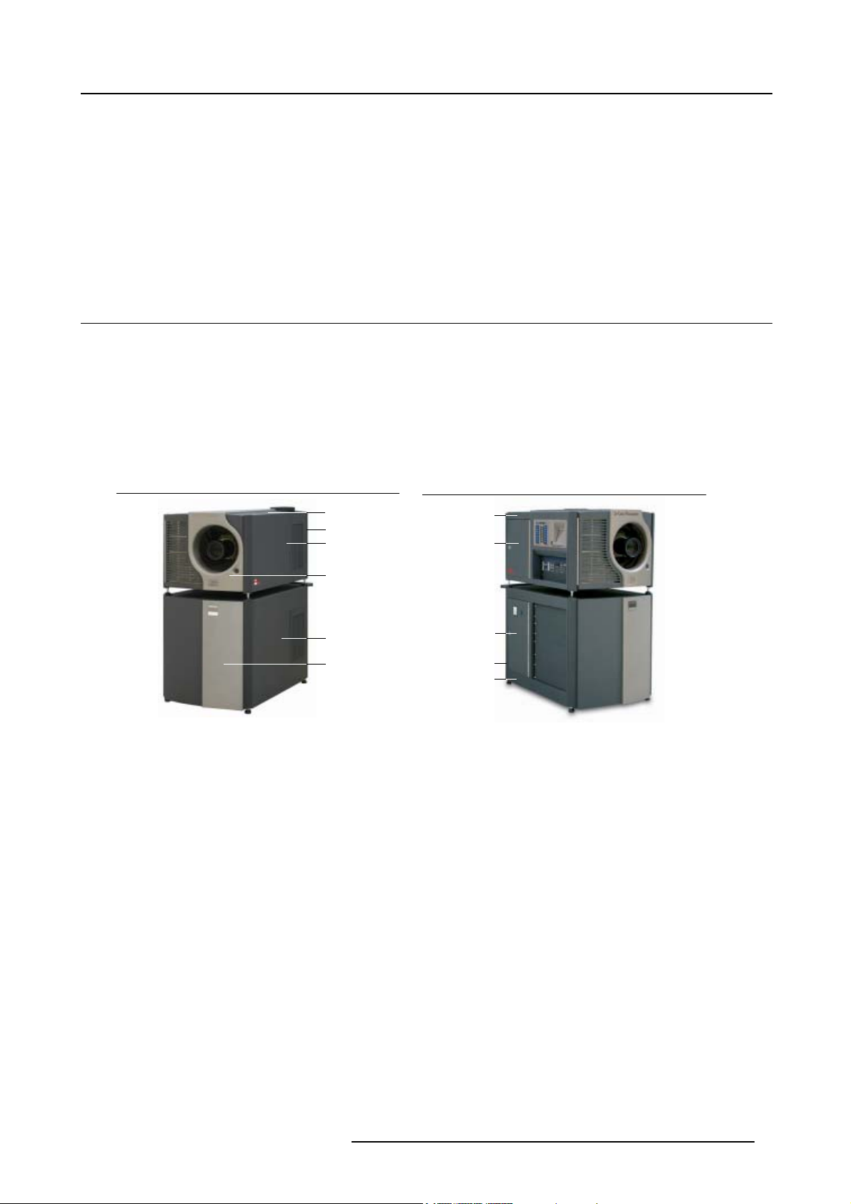
Image 2-1
A Top cover projector head
B Rear cover projector head
C Side cover right projector head
D Front cover projector head
E Side cover projector pedestal
F Front cover projector pedestal
A
B
C
D
E
F
Image 2-2
G Side cover left projector head
H Access door lamp unit
I Access door lamp power supply
J Rear cover projector pedestal
K Side cover left projector pedestal
G
H
I
J
K
R5976907 D-CINE PREMIERE DP100 02/11/2005
5
Page 10
2. Check up the D-Cine Premiere DP100
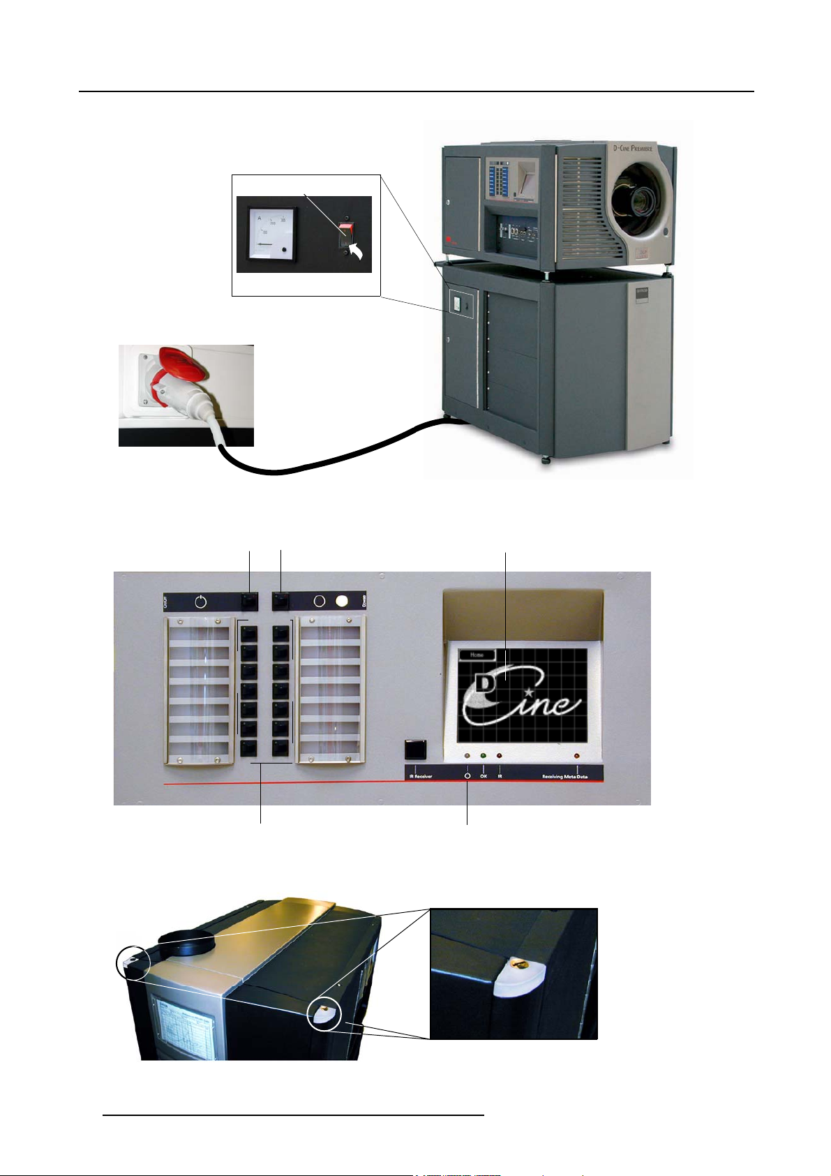
2.2 Power Connection to Wall Outlet
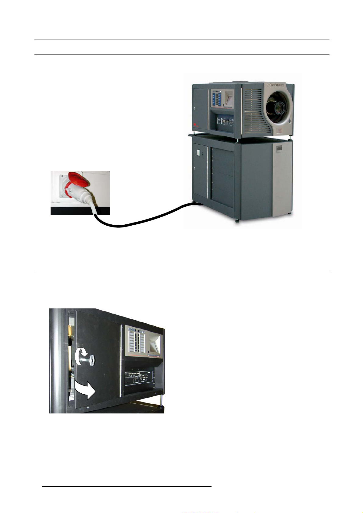
Power plugged into wall outlet!
Image 2-3
Power connection to Wall outlet
2.3 Pressure in the Cooling System
Access to the manometer
1. Insert the lock key in the k eyhole on the lamp house door and turn the key to the right to unlock the door. (image 2-4)
2. Turn the door to the right to open.
Image 2-4
Lamp door opening
Reading out the pressure value on the manometer
At the top, inside the projector head, a man ometer is provided, being part of the cooling circuit. The value in normal operation
condition must be approximately 1 Bar with a minimum of 0.5 Bar.
6
R5976907 D-CINE PREMIERE DP100 02/11/2005
Page 11
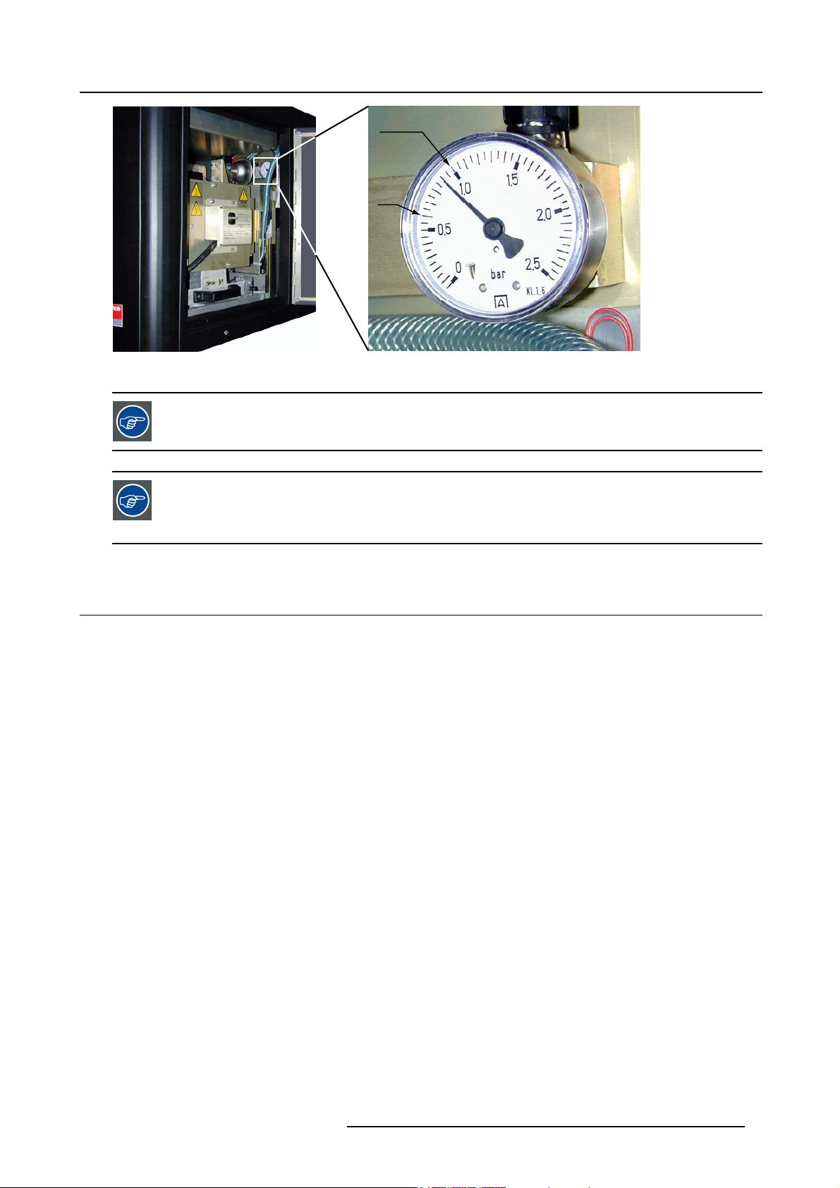
Image 2-5
Manometer view
2. Check up the D-Cine Premiere DP100
Max.
Min.
A rapid/significant drop in system pressure indicates leakage. Verify whether the cir
signs of liquid leakage. Refer the problem to a qualified Barco service center.
Minor drops in pressure over time are to be expected. Once the minimum pressure is reached, pre-pressurize
to approximately 1 bar (projector off).
If this cannot be achieved, proceed to liquid re-filling procedure (Described in the installation manual of the
projector).
2.4 Exhaust on Dirt
Access to the Exhaust
Access to the exhaust for checkup, see "Cleaning the Blower on top of the Projector Head", page 27.
cuit shows any visible
R5976907 D-CINE PREMIERE DP100 02/11/2005
7
Page 12

2. Check up the D-Cine Premiere DP100
8 R5976907 D-CINE PREMIERE DP100 02/11/2005
Page 13
3. Starting up the D-Cine Premiere DP100
3. STARTING UP THE D-CINE PREMIERE DP100
Overview
• Switching On the projector
• Starting Image Projection
3.1 Switching On the projector
HowtoswitchOntheprojector
1. First, carry out the projector check up (see "Che ck up the D-Cine Premiere DP100", page 5).
2. Press the tumbler switch (A) in the “I” p osition (ON state indicated b y a visible red section of the switch). (image 3-1)
Note: Ensure that the power tumbler switch on the input panel on the projector head is in the ON state
After power On switching, the projector boots up for a while (±30s) and the final status of the projector is as follows: (image 3-2,
image 3-3)
Projector Control Panel (image 3-2)
Lamp Off The lamp is OFF , indicated by the built-in Red LED ON (A).
Dowser closed
Push button controls
Control panel status After boot up of the projector without (power) FAILURE detection, the status LED
Touch screen panel
Panel lighting Blue panel lightning is on.
Projector Cooling System
Fans All Fans aswelltheExhaust are activated, starting the air ventilation in t
Engine cooling The water pump in the cooling circuit is activated, starting the liquid circu
Projector Status Lights (image 3-3)
Status lights While the projector is booting up, the status light will be flashing red.
Explanation
The dowser is closed, indicated by the built-in Red LED ON (B).
The last pressed button is selected, indicated by the built-in Green LED On (D).
changes over from Red to Green (C).
The start up menu “HOME” is displayed on the screen (E).
Explanation
he projector.
lation
into the engine and the radiator.
Explanation
After boot up of the projector without ERROR detection, the color of the status
Lights (A) are Green. When an error is detected, the color changes to Red.
R5976907 D-CINE PREMIERE DP100 02/11/2005 9
Page 14
3. Starting up the D-Cine Premiere DP100
A
B
A
Image 3-1
Switching ON the projector
MACRO 01
MACRO 03
MACRO 05
MACRO 07
MACRO 09
MACRO 11
MACRO 13
Image 3-2
Control panel status after switching on
D
E
MACRO 02
MACRO 04
MACRO 06
MACRO 08
MACRO 10
MACRO 12
MACRO 14
C
A
Image 3-3
Status lights on pr
10 R5976907 D-CINE PREMIERE DP100 02/11/2005
ojector head
Page 15
3.2 Starting Image Projection
A
B
Overview
• Using the Button control Panel
• Using the Touch Screen Panel
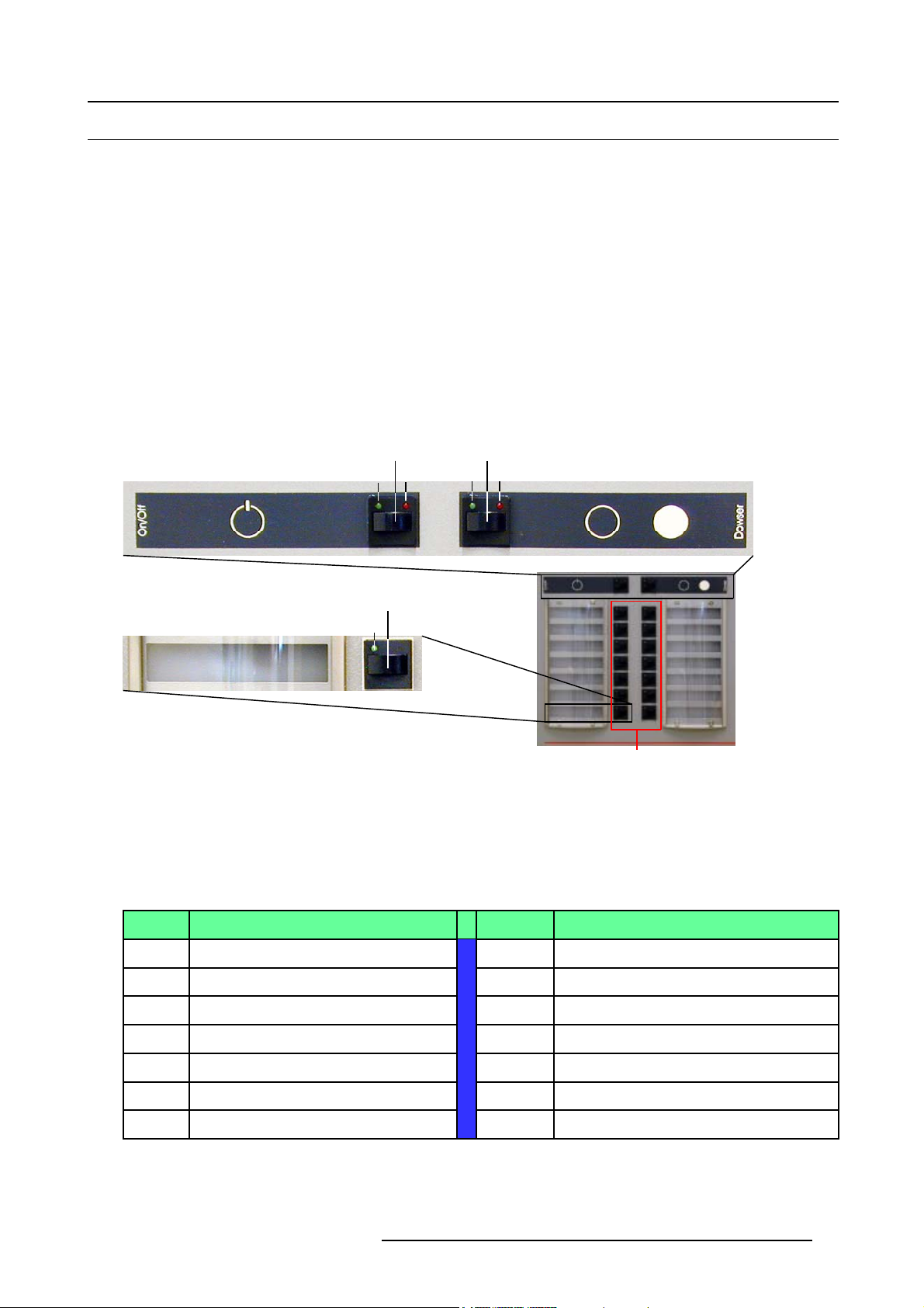
3.2.1 Using the Button control Panel
How to start image projection
1. Press the lamp ignition button (A). (image 3-4)
The lamp ignite, indicated by the built-in Green LED ON (A2).
2. After ignition of the lamp, press the dowser button (B) (image 3-4)
The dowser opens, indicated by the built-in Green LED ON (B2).
3. Press the desired selection button (D),1 to 14 (image 3-4)
The selected button is i ndicated by the built-in Green LED ON (D1). The projector starts executing the macro actions.
1
A
2
A
3. Starting up the D-Cine Premiere DP100
1
2
B
B
D
1
D
Image 3-4
Bulb ignition and Dowser opening
Factory preset of the buttons
The Buttons 1 to 10 are preset to be used for presenting c inem a events such as first-run movies stored on a digital media storage
device.
TheButtons11to14arepresettobeusedtodisplay“
non-cinema source, connected to the built-in ACSAR 2.
Button Macro Button Macro
1 292A_P7_FLAT_1280 2
3 292A_P7_FLAT_1920 4
5
7
292A_P7_FLAT_2048 6
292A_P3_FLAT_1280 8
alternative content” originating from a standard definition or high definition
292A_P7_SCOPE_1280
292A_P7_SCOPE_1920
292A_P7_SCOPE_2048
292A_P3_SCOPE_1280
D
9 292A_P3_FLAT_1920 10
11
13
R5976907 D-CINE PREMIERE DP100 02/11/2005 11
ACSAR_Input 1
ACSAR_Input 3
12
14
292A_P3_SCOPE_1920
ACSAR_Input 2
ACSAR_Input 4
Page 16
3. Starting up the D-Cine Premiere DP100
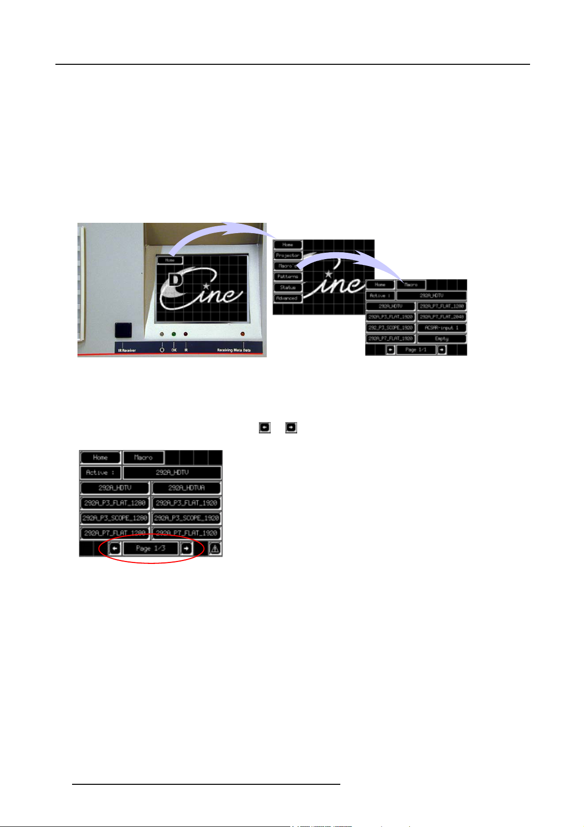
3.2.2 Using the Touch Screen Panel
How to start image projection
1. Start lamp ignition and opening dowser w ith the toggle buttons on the control panel (see "Using the Button control Panel", page
11).
2. Successively press touch button Home and Ma cro’s. (image 3-5)
The macro menu is displayed. The macro which is active is displayed next to field with inscription “Active”.
If the active macro is linked to one of the fourteen push buttons on the control panel, then, the corresponding LED to the button
will light up Green.
3. Select the macro you desire to play by p ressing the corresponding touch button.
The projector starts executing the macro actions.
Image 3-5
Touch panel menu Macro’s
About stored Macro’s
Many macro’s canbeprogrammedwiththeD-Cine communicator and stored in the projector. Because the touch screen can display
maximum 8 different macro’s, the number of macro’s (if more than 8) is split over more pages.
To run through the pages, two arrow touch buttons
number.
Image 3-6
Macropageselection
The page numbering includes consecutively the displayed page and th e number of pages, for example “page 1/3” ( page 1 of 3
pages).
and are provided at the bottom of the screen with in between the page
12
R5976907 D-CINE PREMIERE DP100 02/11/2005
Page 17

4. Cinema Operation
4. CINEMA OPERATION
Introduction
This section explains how trained operators can use the projecto r for presenting cinema events such as first-run movies stored an
a digital media storage device.
The digital media storage device or cinema server is connected to one of the A or B input port on the input panel.
Input Panel
Image 4-1
Cinema server connection
B
A
to SMPTE A or B
4.1 Selecting the Cinema Source
Using the Button control panel
1. The facto ry button assignment to a macro is represented in illustration below: (image 4-2)
Note: Buttons 1 to 10 represent respectively pre-configured cinema displays.
2. Press the button according the cinema source to be displayed.
The assigned macro is activated resulting in a full image display according the cinema processing procedure (pre-defined by the
producers).
The button built-in LED will be on, indicating the active macro.
Cinema Server
292A_P7_FLAT_1280
292A_P7_FLAT_1920
292A_P7_FLAT_2048
292A_P3_FLAT_1280
292A_P3_FLAT_1920
ACSAR 1
ACSAR 3 ACSAR 4
Image 4-2
Pre-configured buttons
292A_P7_SCOPE_1280
292A_P7_
SCOPE
292A_P7_
SCOPE
292A_P3_
SCOPE
292A_P3_
SCOPE
ACSAR 2
_1920
_2048
_1280
_1920
Using the Touch Screen Panel
1. Successively press touch button Home and Ma cro’s. (image 4-3)
First pageofthe stored macros (
next to the field inscription “Active”.
If the active macro is linked to one of the fourteen push buttons on the control panel, then, the corresponding LED to the button
will light up Green.
2. Press the touch button accordi
R5976907 D-CINE PREMIERE DP100 02/11/2005
divided over3p ages of 8 macros) isdisplayed(page1/3). Themacro which is active isdisplayed
ng the cinema source to be displayed.
13
Page 18

4. Cinema Operation
The assigned macro is activated resulting in a full image display according the cinema processing procedure (pre-defined by the
producers).
Image 4-3
Macros selection
14 R5976907 D-CINE PREMIERE DP100 02/11/2005
Page 19

5. Non-Cinema Operation
5. NON-CINEMA OPERATION
Overview
• ACSAR 2 Input facilities
• Monitoring ACSAR 2 select ed Source
• Selecting an ACSAR 2 Source
• Remote Control Functionality
Introduction
This section explains how to display “alternative content” originating from a standard definition or high definition non-cin
Such a source routes to a DVI (Digital Visual Interface) port in the D-Cine Premiere DP100 projector head, and bypass cinema
processing when selected.
ACSAR 2
Input 1
Input 2
Input 3
Input 4
ema source.
Image 5-1
Location of the ACSAR 2
5.1 ACSAR 2 Input facilities
Input facilities
The ACSAR 2 can be filled up with a m ixture of the following input modules (maximum 4):
Input module
DVI input R9850960
HD-SDI input
RGB analog (up to UXGA)
SDI input
S-Video/Composite Video input
YUV/RGsB input
For further info
the installation manual of the D-Cine Premiere DP100.
about source connection to the input module, File service, Picture tuning, Window and Layout adjustment, refer to
Order number
R9853130
R9853120
R9850970
R9850920
R9850940
5.2 Monitoring AC
SAR 2 selected Source
Monitoring
A monitor, connected to output “ACSAR 2 Preview” on the D-Cine Premiere DP100 input panel, displays in preview the imag e on
the output o f the Alternative Content switcher.
R5976907 D-CINE PREMIERE DP100 02/11/2005
15
Page 20

5. Non-Cinema Operation
RGBHV
Image 5-2
Monitoring ACSAR 2 output signal
5.3 Selecting an ACSAR 2 Source
About Macro’s files
For any display, the projector interprets incoming signal data according to a selectable “Macro file” defined a t the time of installation
or later (e.g. w ith each subsequent release of a new digital cinema fe ature), and stored in projector memory.
Each file is essentially a collection of processing/display settings optimized for a particular cinema feature or alternative non-cinema
content, enabling consistent presentations with m inimum further adjustment.
A file (macro) is represented by an assigned “button” on the control panel (max 14). More files can be selected via the macro menu
on the Touch Pane l Controller.
Using the Button control panel
1. The facto ry button assignment to a macro is represented in illustration below: (image 5-3)
Note: Button 11 to 14 represent respectively an ACSAR 2 input activation.
2. Press button:
- 11: selects the ACSAR 2 input 1, resulting in a full image display of the connected source.
- 12: selects the ACSAR 2 input 2, resulting in a full image display of the connected source.
- 13: selects the ACSAR 2 input 3, resulting in a full image display of the connected source.
- 14: selects the ACSAR 2 input 4, resulting in a full image display of the connected source.
A green LED On, bu ilt-in the button, indicates the activated macro for that bu
SCOPE
SCOPE
SCOPE
SCOPE
_1920
_2048
_1280
_1920
292A_P7_FLAT_1280
292A_P7_FLAT_1920
292A_P7_FLAT_2048
292A_P3_FLAT_1280
292A_P3_FLAT_1920
ACSAR 1
ACSAR 3 ACSAR 4
Image 5-3
ACSAR 2 representing buttons
292A_P7_SCOPE_1280
292A_P7_
292A_P7_
292A_P3_
292A_P3_
ACSAR 2
tton.
Using the Touch Screen Panel
1. Successively press touch button Home and Ma cro’s. (image 5-4)
First page of the stored macro (divided over 3 pages of 8 macros) is displayed (page 1/3). The macro which is active is displayed
next to the field inscription “Active”.
If the active macro is linked to one of the fourteen push button on the control panel, then, the corresponding LED to the button
will light up Green.
2. Press the arrow touch button
3. Press the corresponding Acsar touch butt
16
to display the page, including the ACSAR 2 macros (in example page 2 and 3).
on , 1 to 4 (refer to the input module in the ACSAR 2).
R5976907 D-CINE PREMIERE DP100 02/11/2005
Page 21

The macrowillbeexecuted, resulting in a full imagedisplayof the source connected to therespectiveinputmodule of the ACSAR
2.
Because these macros are also assigned to a button on the control panel, the LED associated to the button will be On.
Image 5-4
Macros selection
5.4 Remote Control Functionality
5. Non-Cinema Operation
5.4.1 Infra Red Reception on D-Cine Premiere DP100
Operation of the RCU
On the front of the button panel, a window (A) is provided behind wh ich an infra red reception diode is mounted.
To send commands to the projector head, point the front of the Remote Control to that window.
A
C
B
Image 5-5
Pointing the Remote Control
Function of the control LED’s below touch button panel
Ref.
B
C
R5976907 D-CINE PREMIERE DP100 02/11/2005 17
LED name Description
OK Lighting up of the LED indica tes acknowledge of the sent command
IR
Blinking of the LED indicates infra red reception
Page 22

5. Non-Cinema Operation
5.4.2 Remote Control Functions
Function of the RCU keys
Pause On/Off
Lamp On/Off
Lens keys
Macro keys
No function
Menu keys
Address key
No function
IR LED
ACSAR Input
Image Freeze
Text On/Off
Image keys
No function
Image 5-6
Function of the RCU keys
Ref.
1 Menu keys Keys used to enter, to exit, to scroll in....the menus
2 Address key
3
4
5
6 Macro keys
7
8
9
Key name Description
(Recessed key) Allows to match the address of the projector.
Procedure: press a digit key , 0 to 9, while pres
Pause On/Off Press pause key to stop image display. The image disappear but full power is retained fo r
Lamp On/Off After power on the projector, pressing thi
Lens keys Press this key to call up the lens menu. Further, use the menu keys to execute lens
IR L ED
ACSAR 2 input Press this key to select t he ACSAR input
Image freeze Press to freeze the displayed image
immediate restart when pause k ey is pressed again.
turns of the lamp.
adjustment.
Pressingadigitkey,0to9,activateth
Blinks (together with the background lighting) when a key is pressed. Is a visual indication
of the proper working of the remote control (Battery load).
image layout (Full 1, 2, 3 or 4 or a combination of the 4 - each image displayed in a quarter
of the window - or the 4 at the same time.
(see key F5)
s key starts ignition of the lamp. Pressing again,
e respective macro in s equence of storing.
menu. Further, use the menu keys to select the
from an ACSAR 2 after the input has been chosen
sing the address key.
18 R5976907 D-CINE PREMIERE DP100 02/11/2005
Page 23

5. Non-Cinema Operation
Ref.
10
Key name Description
Text On/Off Press to deactivate or reactivate the On Screen Dialog Boxes and Menus on projection
screen (not applicable on the image preview m o nitor).
11 Image keys
Use these keys to adjust the image display performances.
PHASE key: adjustable for Data sources only.
TINT key: adjustable for NTSC video sources only.
5.4.3 Adjusting the Non-Cine Display
Overview
The projector has a box like menu structure which allows easy access to different menu items for setting up source loading, image
layout and projector parameters.
Menu Structure
File Sevice
Picture Tuning
Adjustment Mode
Window Adjustment
layout Adjustment
Main Menu
Load
Edit
Rename
Copy
Delete
Options
Color Temperature
Noise Reduction
Input Balance
Select Source
Position
Z-Order
Color Key
Alpha Blend
Load Layout
Rename Layout
Add Windows
Remove Window
Edit Window
Keystone
Blanking
Input Slots
Configuration
Internal Patterns
Buttons
Macros
Identification
Change Projector Address
Communication
Lamp
Dimming/CLO
Convergence
Diagnostic
Image 5-7
Overview Menu structure
Installation Mode
Service mode
For more detail about setting up the different items, please refer to the installation manual of the D-Cine Premiere DP100.
R5976907 D-CINE PREMIERE DP100 02/11/2005
19
Page 24

5. Non-Cinema Operation
20 R5976907 D-CINE PREMIERE DP100 02/11/2005
Page 25

6. SwitchingOfftheD-CinePremiereDP100
A
B
6. SWITCHING OFF THE D-CINE PREMIERE DP100
Procedure for switching off the projector
• Close the dowser.
• Switch off the lamp
• Switch off the projector
6.1 Stop Image Projection
How to stop image projection
1. Press the dowser button (B). (image 6-1)
The dowser shuts, indicated by the built-in Red LED ON (B1).
2. Press the lamp ignition button (A) (image 6-1).
The lamp turns off, indicated by the built-in Red LED ON (A1).
1
A
2
A
1
2
B
B
Image 6-1
Bulb and Dowser switching off
6.2 Powering off the projector
CAUTION: To ensure maximum bulb life, first allow the lamphouse blower and the exhaust system run for at
least ten minutes after extinguishing the b
How to power off the projector
1. Press the tumbler switch (A) in the “O” position (OFF state) (image 6-2)
All parts of the projector have been powered off.
2. If the projector will not be used for a long pe
R5976907 D-CINE PREMIERE DP100 02/11/2005
riod, pull out the power connector from wall outlet.
ulb, and then power off the projector.
D
21
Page 26

6. SwitchingOfftheD-CinePremiereDP100
A
Image 6-2
Powering off the projector
22 R5976907 D-CINE PREMIERE DP100 02/11/2005
Page 27

7. Maintenance of the D-Cine Premiere DP100
7. MAINTENANCE OF THE D-CINE PREMIERE DP100
Overview
• Lamp Unit replacement
7.1 Lamp Unit replacement
Overview
• Removal of the Lamp House
• Installation of the Lamp Unit
7.1.1 Removal of the Lamp House
7.1.1.1 Access to lamp Unit
How to access the lamp unit
1. Insert the lock key in the keyhole on the lamp house door. (image 7-1)
2. Turn the key to the right to unlock the door.
3. Turn the door to the right to open.
Image 7-1
Access to lamp casing
7.1.1.2 Removal of the Lamp Unit
CAUTION: Lamp casing is very hot after operation. To avoid burns, let the projector cool down for at least 15
minutes before proceeding to the lamp unit replacement.
How to remove the Lamp unit
1. Loosen the 2 spring screws (A) securing lamp assembly to projector base.
2. Grip the lamp assembly by the bottom handle
Caution: Bew are of the weight of the lamp assembly. Take the necessary precautions to avoid personal injury.
3. Grip the lamp assembly by both handles (C) and carefully remove the lamp assembly from main frame.
4. Place the lamp assemb ly on a stable support
R5976907 D-CINE PREMIERE DP100 02/11/2005
(B)and partially slide it out of the projector main frame. (image 7-2)
23
Page 28

7. Maintenance of the D-Cine Premiere DP100
C
A
Image 7-2
Lamp casing removal
B
A
C
7.1.2 Installation of the Lamp Unit
7.1.2.1 Installation of the lamp unit in the projector head
How to install the lamp unit
1. Place the lamp unit on the lamp base in the projector, lining up the lamp unit foot with the slots on the base. (image 7-3)
2. Push the lamp unit foot fully into the slots. (image 7-4)
3. Secure the position of the lamp unit by tightening the spring screws (A).
4. Proceed to reset the lamp parameters, see D-Cine Communicator manual.
5. To ensure maximum light output, proceed to the Xenon Bulb lamp X-Y-Z alignment (see chapter “Alignment of the Xenon bulb
lamp” in the installation manual).
Image 7-3
Moving the lamp unit foot into the base
24 R5976907 D-CINE PREMIERE DP100 02/11/2005
Page 29

7. Maintenance of the D-Cine Premiere DP100
Image 7-4
Securing the lamp unit
Before using the lamp, Insert the lamp parameters via the D-Cine Communicator software.
7.1.2.2 Closing the Lam
Installation o
fore, first proceed to lamp alignment before closing the lamp house door.
p house door
f a new lamp requires alignment of the lamp position when installed in the projector head. There-
How to lock the lamp house door
1. Close the door. (image 7-5)
2. Turn the key counterclockwise to lock the door.
A
A
Image 7-5
Locking the lamp house door
R5976907 D-CINE PREMIERE DP100 02/11/2005 25
Page 30

7. Maintenance of the D-Cine Premiere DP100
26 R5976907 D-CINE PREMIERE DP100 02/11/2005
Page 31

8. CLEANING AIR DUCT
d
Overview
• Cleaning the Blower on top of the Projector Head
• Cleaning the Dust filters
8.1 Cleaning the Blower on top of the Projector Head
This item should be cleaned approximately every six months under normal environment conditions. Equipment in very dusty or otherwise contaminated areas may require more frequent maintenance.
8. Cleaning Air Duct
CAUTION: Power off the projector, using the main power switch on the projector pedestal and allo
of the Xenon bulb lamp for at least 15 minutes before proceeding to blower cleaning.
w cooling
How to clean the Blower
The blower impeller and motor should be cleaned to prevent build up of contaminant on
the blower motor. Proper operation of the lamp is dependent on providing adequate cooling air flow. A dirty blower may not provide
proper air flow, causing the lamp and lamp house to operate at temperatures that are higher than desirable.
1. Remove the lamp house to access the blower (see "Removal of the Lamp Unit", page 23)
2. Clean loose dirt from blower impeller with vacuum cleaner. (image 8-1)
3. Use brush with hot water and suitable detergent to remove dirt that cannot be vacuumed off.
both the blower impeller surfaces and on
Lamp house remove
Image 8-1
Exhaust blower
8.2 Cleaning the Dust filters
These items should be cleaned monthly under normal environment conditions. Equipment in very dusty or
otherwise contaminated areas may require more frequent maintenance.
If the air filters are not regularly c
heating. Overheating may lead to the projector shutting down during operation.
R5976907 D-CINE PREMIERE DP100 02/11/2005 27
leaned, the air flow inside the projector could be disrupted and cause over-
Page 32

8. Cleaning Air Duct
Location of the air filters
Air filters are placed at the front (A) and at the right side (B) of the projector head.
Image 8-2
Air filter at the front of the projector
A
B
Image 8-3
Air filter at the side of the projector
Removing the air filters
1. Front air filter: grasp the decorative bar of the filter (A) and pull out the air filter of the projector front cover.
2. Side air filter projector head (A): loosen the 2 screws securing the air filter frame to the side cover and remove the filter.
How to clean the air filters
1. Remove most contamination with a vacuum cleaner.
2. Blow remaining dust away with compressed air in an other room or outside.
28
R5976907 D-CINE PREMIERE DP100 02/11/2005
Page 33

9. Image Control
9. IMAGE CONTROL
9.1 Lens Focus test pattern
How to select a test pattern for focus alignment
1. On the touch screen panel, starting from the Home screen, consecutively press touch button Home (1), Patterns (2) and More
(3).(image9-1)
The name of the already active test pattern is indicated just below the screen field Active Test Pattern.
2. Touch the arrow buttons on both sides of the screen field Enable Test Pattern to select the Focus test pattern from the list.
Selected test pattern from the list is displayed in the screen field just above Enable Test Pattern.
: back scrolling in the test pattern list.
-
-
: forward scrolling in the test pattern list.
-
: jump to top of the test pattern list.
: jump to bottom of the test pattern list.
-
3. Press touch button Enable Test Pattern to activate the selected test pattern.
Projector displays the selected pattern and the name of the pattern a ppears in the screen field just below Active test pattern.
(image 9-2)
4. Press touch button Home to return to main menu.
Image 9-1
Test pattern selection
Image 9-2
Focus test pattern
1
2
3
9.2 Lens Adjustment
Overview
For focusing the lens and for vertical and horizontal shifting of the lens, the side cover n earest the lens must be remo ved and the
lens sock must be loosen. Therefore, start first with the projector preparations.
R5976907 D-CINE PREMIERE DP100 02/11/2005
29
Page 34

9. Image Control
Lens zoom ca n be performed without removing any cover.
9.2.1 Preparation of the projector
Removing both side panels
1. Loosen the 2 screws on top side and the 2 screws on the bottom side of the cover nearest the lens. ( imag e 9-3)
2. Tilt the cover a little and lift up for removal.
Image 9-3
Right side cover removal
Loosen the dust sock around the lens
1. Pull out the sock fixations from the lens holder and slide it to the front of the
image). (image 9-4)
Image 9-4
Dust sock removal
9.2.2 Lens Zoom
Zoom can be performed without removing any cover.
projector (only a few points are indicated on the
How to zoom?
1. Turn the lens barrel, on the second half of the lens, left or right until the desired zoom is reached. (image 9-5)
An end of range notch will indicate that the lens is on its minimum or ma ximum zoom.
30
R5976907 D-CINE PREMIERE DP100 02/11/2005
Page 35

Image 9-5
Lens Zoom
9.2.3 Lens Focus
The focus adjustment is located just below the lens on the left side (C on image 9-6). Remove the side cover
nearest the lens and open the dust sock around the lens.
9. Image Control
How to focus?
1. Loose fixation nut C1. (image 9-6)
2. Turn the knurled torque knob (C2) to the left or to the right until the center of the image is focused (sharp image).
3. Fasten screw C1 again to secure the focus position.
C1
C
Image 9-6
Focus adjustment
C2
9.2.4 Lens Shift
What can be done?
By using the vertical and/or the horizontal shift adjustments on the lens, it is possible to shift the image upwards/downwards (=
vertical shift adjustment) and/or to the left/right (= horizontal shift adjustment)
The shift adjustments are located on the lens holder. The covers must be removed before any shift adjustment
is possible. On image 9-7, A = horizontal shift, B = vertical shift.
How to shift?
1. For a vertical shift, loosen first fixation nut A1. (image 9-7)
R5976907 D-CINE PREMIERE DP100 02/11/2005
31
Page 36

9. Image Control
2. Shift the image by turning the knurled torque knob (A2) clockwise or counter clockwise until the image is on the desired position.
3. Secure this position by fastening nut A1 again.
4. For a horizontal shift, loosen first fixation nut B1.
5. Shift the image by turning the knurled torque knob (B2) clockwise or counter clockwise until the image is on the desired position.
6. Secure this position by fastening nut B1 again.
A
A2
A1
B2B1
B
Image 9-7
Horizontal and vertical shift
32 R5976907 D-CINE PREMIERE DP100 02/11/2005
Page 37

10. Status of the D-Cine Premiere DP100
10.STATUSOFTHED-CINEPREMIEREDP100
Status lights
On top of the projector head, rear side, status lights are built-in in the corners. When no errors, e.g. fan failure, overheating.. are
detected, the color of the status lights is GREEN. When an error occurs, the color of the status lights changes to RED. Information
about the type of error can be retrieved using the D-Communicator or the Touch panel menu.
If you are not familiar with the projector, call for technical assistance.
A
Image 10-1
Status lights on projector head
10.1 Start up of the status function
How to start up
1. Push Home . (image 10-2)
The home menu opens. (image 10-3)
2. Push Status. (image 10-4)
The status menu will be displayed. (image 10-5)
Image 10-2
Start up screen
Image 10-3
Main menu
R5976907 D-CINE PREMIERE DP100 02/11/2005 33
Page 38

10. Status of the D-Cine Premiere DP100
Image 10-4
Status start up
Image 10-5
Status menu
Overview of the Status menu
The status menu conta ins
• Temperature overview
• Voltage overview
• Fan speeds overview
the fo llowing items:
10.2 Temperature overview
To get DMD temperatures and lamp house temperature
1. Push Temperature. (image 10-6)
The DMD and lamp house temperature overview will be displayed. (image 10-7)
The following temperatures are monitored, the m inimum and maximum values are indicated:
-DMDred
- DMD green
- DMD blue
- Lamp house
Image 10-6
Temperature selected
To get extra temperatures
1. Push More →. (image 10-8)
The first extra temperature overview menu will be displayed. (image 10-9)
The following temperatures are monitored:
-Ambient
- Elca box
-Rack
-PFC
2. Push again More →. (image 10-10)
34
Image 10-7
DMD temperature overview
R5976907 D-CINE PREMIERE DP100 02/11/2005
Page 39

The switched mode power supply temperatures are listed. (image 10-11)
- Switched mode power supply 1 primary side
- Switched mode power supply 1 secondary side
- Switched mode power supply 2 primary side
- Switched mode power supply 2 secondary side
10. Status of the D-Cine Premiere DP100
Image 10-8
More temperature overviews selected
Image 10-10
More temperature overviews selected
Image 10-9
Temperature overviews
Image 10-11
Switched mode temperatures overview
How to change the temperature units
1. Push on the T
The units change from °C to °F and vice versa. All values will be recalculated when changing the units.
emperature units button in one of the temperature overview windows. (image 10-12)
R5976907 D-CINE PREMIERE DP100 02/11/2005
35
Page 40

10. Status of the D-Cine Premiere DP100
Image 10-12
10.3 Voltage overview
First voltage overview
1. Push Voltages. (image 10-13)
The first voltage menu will be displayed. (image 10-1
The following voltages are monitored:
- 5V standby
- 12V standby
-3.3V
- 12V
4)
Image 10-13
Status voltages selected
Second voltage overview
1. Push More →. (image 10-15)
36
Image 10-14
First voltage overview menu
R5976907 D-CINE PREMIERE DP100 02/11/2005
Page 41

The secon d voltage overview window will be displayed. (image 10-16)
The following voltages are monitored:
- Lamp fa n Top
- Lamp fan Anode
- Lamp fan Cathode
- Electronic fans
10. Status of the D-Cine Premiere DP100
Image 10-15
Selecting second voltageoverview
Image 10-16
Second voltage overview window
Third voltage overview
1. Push More →. (image 10-17)
The third voltage overview window will be displayed. (image 10-18)
The following voltages are monitored:
- 24 V cooling
- 12 V ACSAR
-TECS
Image 10-17
Selecting third voltage overview window
Image 10-18
Third voltage overview window
10.4 Fan speed overview
First fan speed window
1. Push Fan Speeds. (image 10-19)
The first fan speed overview window will be displayed. (image 10-20)
The following fans are monitored:
- Fan elec box 1
- Fan elec box 2
- Fan elec box 3
- Fan elec box 4
R5976907 D-CINE PREMIERE DP100 02/11/2005
37
Page 42

10. Status of the D-Cine Premiere DP100
Image 10-19
Fan speed selected
Image 10-20
Fan speed overview window
Second fan speed window
1. Push More →. (image 10-21
The second fan speed overview window will be displayed. (image 10-22)
The following fans are monitored:
- Fan sealing
-Fanlamptop
- Fan lamp anode
- Fan lamp cathode
Image 10-21
Selecting seco
nd fan speed overview
)
Image 10-22
Second fan spee
d overview window
Third fan speed window
1. Push More →. (image 10-23)
The third fan speed overview w indow will be displayed. (image 10-24)
The following fans are monitored:
- Fan SPG
- Fan Cold Mirror 1
- Fan Cold Mirror 2
Image 10-23
Selecting third fan speed overview
38 R5976907 D-CINE PREMIERE DP100 02/11/2005
Image 10-24
Thirdfanspeedwindow
Page 43

11. D-Cine Premiere DP100 Info
11. D-CINE PREMIERE DP100 INFO
11.1 Starting up the Menu
How to select!
1. On the touch screen panel, starting from the Home screen, consecutively press touch button Home and Projector. (image 11-1)
On the touch screen appears two fields, named the Lamp Info and the projector Properties.
2. Press the respective touch button to consult the stored info behind (see further).
2
1
Image 11-1
Projector Info
11.2 Lamp info
Run times and strikes
1. Push Lamp info. (image 11-2)
The first lamp info menu will be displayed. (image 11-3)
The following information is given:
Run time
Strikes Number of strikes since the first strike.
Max run time
Run time since the first strike of the lamp (expressed in hours).
Maximum run time allowed for this type of lamp (expre ssed in hours)
Image 11-2
Lamp info selected
wer indications
Po
1. Push More →. (image 11-4)
R5976907 D-CINE PREMIERE DP100 02/11/2005
Image 11-3
Run times and strikes
39
Page 44

11. D-Cine Premiere DP100 Info
The second lamp info menu will be displayed. (image 11-5)
The following information is given:
Power Actual power supplied to the lamp
Nominal power Nominal power to be supplied to the lamp
Maximum power Maximum power allowed to be supplied to the lamp
Minimum power Minimum power allowed to be supplied to the lamp
Maximum current Maximum curre nt through the lamp
Image 11-4
More lamp info
Image 11-5
Lamp power info
Administrative information
1. Push More →. (image 11-6)
The third lamp info menu will be displayed. (image 11-7)
The following informati
Article number
Version
Serial number Serial number of the actual installed lamp
Image 11-6
More lamp info
on is given:
Order number of the lamp
Version of the lamp module
Image 11-7
Administrative information
11.3 Projector properties
Overview
• Projector properties start up
• IP addresses projector
• IP cinema
• Communication
• Touch pan el
40
R5976907 D-CINE PREMIERE DP100 02/11/2005
Page 45

11.3.1 Projector properties start up
How to start up
1. Push Properties. (image 11-8)
The properties window opens. (image 11-9)
11. D-Cine Premiere DP100 Info
Image 11-8
Projector properties selected
11.3.2 IP addresses projector
Use the D-Cine Communicator software to setup the IP addresses.
IP
Internet Protocol. The network layer of TCP/IP. Required for communication with the internet.
Subnet mask
A number that is used to identify a subnetwork so that IP ad dresses can be shared on a local area network.
Default Gateway
A router that serves as a
need a gateway to connect it to a wide area network (WAN) or to the Internet.
DHCP
Dynamic host configuration protocol. DHCP is a communications protocol that lets network administrators manage
centrally and automate theassignmentofIPaddresses in an organization’s network. Using the Internet Protocol, each
machine that can connect to the Internet needs auniqueIPaddress. When an organization sets up its computer users
with a conne ction to the Internet, an IP address must be assigned to each m achine. Without DHCP, the IP address
must be entered manually at each computer and, if computers move to another location in another part of the network,
a new IP address must be entered. DHCP lets a network administrator supervise and distribute IP addresses from
a central point and automatically sends a new IP address when a computer is plugged into a different place in the
network.
Image 11-9
Properties window
n entry point into and exit point out of a network. For example, a local network (LAN) may
Overview
1. Push IP Projector. (image 11-10)
R5976907 D-CINE PREMIERE DP100 02/11/2005
41
Page 46

11. D-Cine Premiere DP100 Info
The IP overview list will be displayed. (image 11-11)
Projector IP
Subnet mask
IP address of built-in Barco controller DIM-PC.
subnet mask addre ss
Default gateway Default gateway address (router address
DHCP
enabled : dynamic IP address used on the projector
disabled : fixed I P address used for the projector
Note: An enabled DHCP, ALWAYS requires an installed network connection to the projector.
Without network connection, the projector goes down in network error, by which the operation
of the projector is no more guara nteed.
Image 11-10
IP projector selected
Image 11-11
IP projector overview
11.3.3 IP cinema
Use the D-Cine Communicator software to setup the IP addresses.
Overview
1. Push IP Cinema. (image 11-12)
The IP overview list will be displayed. (image 11-13)
Cinema IP IP address of the cin
Host name
Subnet
Gateway Default gateway addr
DHCP
ema processing part in the projector
Call name for the projector. This name is associated with the IP address.
subnet mask address
ess (router address)
enabled : dynamic IP ad
dress used on the projector
disabled : fixed IP address used for the projector
42 R5976907 D-CINE PREMIERE DP100 02/11/2005
Page 47

11. D-Cine Premiere DP100 Info
Image 11-12
IP cinema selected
11.3.4 Communication
Overview
1. Push Communication. (image 11-14)
An overview of the commun
Projector address
Baudrate communication velocity
Mode
RS422 Termination ON or OFF. Only used when Mode is RS422.
Image 11-13
IP cinema overview
ication settings will be given. (image 11-15)
communication address of the projector
RS232 or RS422
Image 11-14
Communication properties selected
11.3.5 Touch panel
Overview
1. Push Touch panel. (image 11-16)
The touch panel overview menu will be displayed. (image 11-17)
This pane l gives the software version of the touch panel.
R5976907 D-CINE PREMIERE DP100 02/11/2005
Image 11-15
Communication properties
43
Page 48

11. D-Cine Premiere DP100 Info
Image 11-16
Touch panel overview selected
Image 11-17
Touch panel software version
44 R5976907 D-CINE PREMIERE DP100 02/11/2005
Page 49

INDEX
Index
A
Access doors 5
Check up 5
ACSAR 2 selected source 15
Monitoring 15
Air duct 27
Cleaning 27
B
Blower 27
Cleaning 27
Button co ntrol panel 11
Image projection 11
C
Check up 5
Access doors 5
Covers 5
Projector 5
Cinema operation 13
Cinema source 13
Selecting 13
Cleaning 2 7
Air duct 27
Blower 27
Dust filter 27
Closing 25
Lamp ho use door 25
Cooling s ystem 6
Pressure 6
Covers 5
D
Dirt 7
Exhaust 7
Dust filter 27
Cleaning 27
E
Exhaust 7
Dirt 7
F
Functionality 17
Remote Control 17
I
Image 11
Projection 11
Image Control 29
Image projection 11–12, 21
Button control panel 11
Stop 21
Touch screen panel 12
Info 39
Projector 39
Input facilities 15
Installation 24
Lamp unit 24
IR reception 17
L
Lamp house 23
Removal 23
Lamp house door 25
Closing 25
Lamp unit 23–24
Access 23
Installation 24
Removal 23
Replacement 23
Lens adjustment 29–31
Focus 31
Projector preparation 30
Zoom 30–31
Lens focus 29
M
Maintenance 23
Projector 23
N
Non-Cine display 1 9
Adjusting 19
Non-Cinema operation 15
P
Power c onnection 6
Powering off 21
Projector 21
Pressure 6
Cooling system 6
Projection 11
Image 11
Projector 5, 9, 21, 23, 33, 39
Check up 5
Info 39
Maintenance 2 3
Powering off 21
Starting up 9
Status 33
Switching off 21
Switching On 9
R
RCU functions 18
Remote Control 17
Functionality 17
Removal 23
Lamp h ouse 23
Lamp unit 23
Replacement 23
Lamp unit 23
S
Safety instructions 3–4
Cabinet maintenance 4
General 3
Optical performances 4
Service 4
Ventilation 3
Selecting 13, 16
ACSAR 2 source 16
Cinema source 13
Starting up 9
Projector 9
Status 33
Projector 33
Stop 21
R5976907 D-CINE PREMIERE DP100 02/11/2005
45
Page 50

Index
Image projection 21
Switching off 21
Projector 21
Switching On 9
Projector 9
T
Touch panel 33–34, 36–37, 39–43
Projector functions 39–43
Communication 43
IP addresses projector 41
IP cinema 42
Lamp info 39
Properties 40
Properties start up 41
Touch panel properties 43
Status 33–34, 36–37
Fan speed 37
Startup 33
Temperature 34
Voltage 36
Touch screen panel 12
Image pro jection 12
46
R5976907 D-CINE PREMIERE DP100 02/11/2005
Page 51

Revision Sheet
To:
Barco nv Digital Cinema/Documentation
Noordlaan 5, B-8520 Kuurne
Phone: +32 56.36.84.93, Fax: +32 56.36.88.62
E-mail: service.digitalcinema@barco.com, Web: www.barco.com
From:
Date:
Please correct the following points in this documentation (R5976907/00):
page
wrong
correct
R5976907 D-CINE PREMIERE DP100 02/11/2005
 Loading...