

Page 1
DATA 708
R9002120
R9002129
REPLACEMENT OF A PICTURE TUBE
WARNING: CRT HANDLING
The picture tube encloses a high vacuum and care must be taken not to bump or to
scratch the picture tube as this may cause the tube to implode resulting in personal
injury and property damage. Shatterproof goggles must always be worn by individu-
als while handling the CRT or installing it in the projector.
Do not handle the CRT by the neck.
WARNING
TURN OFF THE PROJECTOR AND UNPLUG THE POWER CORD
BEFORE PROCEEDING TO THE REPLACEMENT OF A PICTURE TUBE
I. Removing and disassembling the defective picture tube.
Getting Access to the picture tube
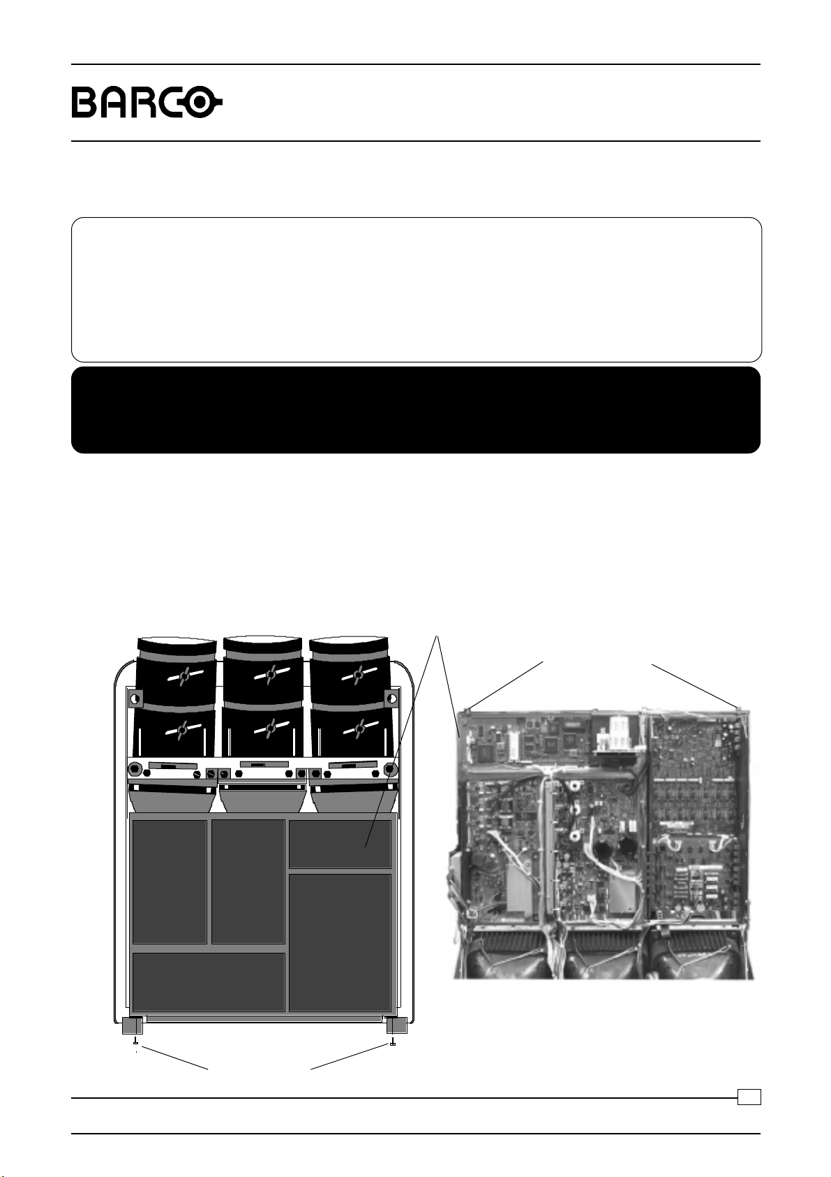
1. Remove the top cover of the projector (please refer to the projector installation manual).
2. Loosen the two locking screws of the module frame.
3. Open the module frame by pivoting it towards the front of projector.
Module frame
Retaining screws
Retaining screws
Replacement of a picture tube
1
Date : 08/06/99
Page 2
DATA 708
Electrical disconnection
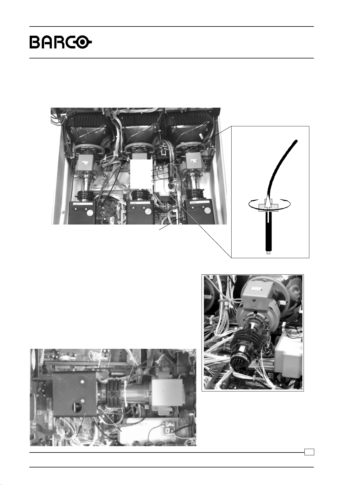
4. EHT lead disconnection
Pull out the EHT lead of the defective picture tube from the EHT splitter.
EHT lead
Red
Green
Blue
R9002120
R9002129
To pull out
Fig. 1
5. Picture tube drive module removal
Cut the cable-tie indicated with A on the picture below,
loosen it and remove it.
Disconnect the CRT ground plug (indicated with B) of
the defective picture tube.
Loosen the gear clamp of the Picture tube drive module
(indicated with C).
Carefully pull the module (indicated with D) back to slide
the CRT socket off from the end of the CRT.
B
CRT ground plug
A
To secure
To open
Ì
C
D
Replacement of a picture tube
Fig. 2
2
Date : 08/06/99
Page 3
DATA 708
CRT unit removal
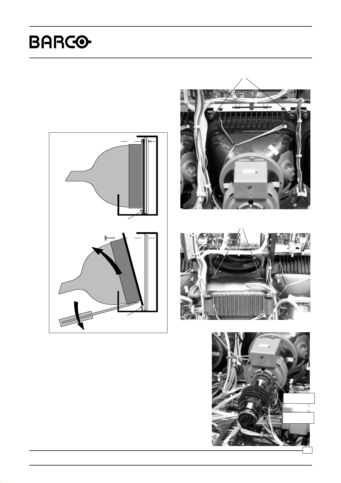
6. Remove the two bolts, holding the CRT unit
to the CRT main frame.
Pull upwards the CRT unit while using a
screw driver to push the CRT out of the clips
at the bottom, to remove the CRT unit.
R9002120
R9002129
Bolts
clips
clips
Fig. 3
Removing the deflection unit and the stigmator magnets
- Loosen the gear clamp of the stigmator
magnets unit.
- Loosen the gear clamp of the deflection unit.
Clips
- Slide the stigmator off from the end of the
CRT.
- Remove the mu-metal
- Slide the deflection unit off from the end of
the CRT.
Replacement of a picture tube
Gear clamp
Deflection unit
Gear clamp
Stigmator unit
Fig. 4
3
Date : 08/06/99
Page 4

DATA 708
R9002120
R9002129
II. Placement of the new picture tube.
1. Remove the CRT ground unit from the defective picture tube and reinstall it on the new picture tube.
CRT ground unit
2. Reinstall the two units, stigmator and deflection yoke, on the picture tube neck.
3. Re-install the mu-metal by wrapping it around the neck of the picture tube, then sliding one side a little
under the clamping gear of the deflection unit and the other side under the clamping gear of the stigmator.
Fix it with a cable-tie. Be sure to also fix the discharging wire as indicated.
4. Secure the respective gear clamps (see Fig. 4) of the stigmator and deflection unit.
5. Place the picture tube unit correctly on its two clips and push it downwards to fit. Secure the position with
the two bolts (see Fig. 3).
6. Plug in the EHT lead of the installed picture tube on the EHT splitter and lock the connector (see Fig. 1).
7. Push the CRT Socket module on the picture tube (see Fig. 2).
8. Secure the gear clamp of the Picture tube drive module.
9. Reconnect the CRT ground plug.
Replacement of a picture tube
4
Date : 08/06/99
Page 5

DATA 708
Neutral position
4-pole rings
2-pole rings
R9002120
R9002129
III. Picture tube alignment
Introduction Before starting the alignment of the new picture tube, the projector must warm
up for at least 15 minutes at a medium brightness and contrast.
If a set of three tubes must be replaced, it is advisable to start with the
replacement of the red and blue tubes first, and using the green as the
reference.
Proceed then with the replacement of the green tube, using now one of the
other colors tubes as the reference.
A. Replacement of a complete
set of three tubes
B. Replacement of one or
two tubes
C. Adjustments applicable
to the three tubes
Apply an external crosshatch pattern at 15 kHz or use the internal crosshatch.
Align the optical and electrical focus of the tube.
Rotate the deflection yoke until the horizontal lines of the crosshatch are
levelled on the screen.
Tighten now carefully the screw of the gear clamp of the deflection yoke.
Center the picture on the CRT faceplate (refer to explanation 'Raster
centering').
Note: alignment of the stigmators will change again its position, if so, realign
raster centering.
In such case, the remaining tube can be used as the reference for
centering and positioning of the new tubes.
Preparation
- Proceed to quick optical lens focusing (please refer to the projector
installation manual).
Replacement of a picture tube
- Adjust the 2-pole and 4-pole
magnetic rings on the CRT neck in
their neutral position (see illustration on next page).
- Select a source that will generate
a field of small dots and
crosshairs.
5
Date : 08/06/99
Page 6

DATA 708
Adjustment of the stigmators (4-pole magnet ring closest to the deflection yoke)
- Lower the brightness and increase the contrast.
- Overdrive the midpoint focus by adjusting the lens focusing for the respective
CRT.
- Adjust the four pole rings until the defocused dots are circular.
- Realign the electrical and optical focus.
- Reposition the raster as described earlier.
- Due to mutual influence between the stigmators, focus and centering, it is
advised to repeat above a couple of times.
Adjustment of the 2-pole magnets (the rings closest to the CRT socket)
- Underdrive the electronic focus by adjusting the left arrow key of the RCU
for the respective CRT.
R9002120
R9002129
- Adjust the 2-pole magnets rings by rotating one or both up to a point where
the 'shading' of both sides of the vertical and horizontal lines is equal (see
figure).
ab
- Realign the electrical and optical focus.
- Repeat the alignment of the stigmators if necessary, as both adjustments
(stigmator and 2-pole magnets) influence each other.
Re-alignment of the image width coil(s)
- Decrease the contrast and increase the brightness to reveal the background
raster.
- Refer to sheet 'Deflection module R762447' in this manual for the alignment
of the image width coils.
a<b
c<d
c
d
a' b'
a'=b'
c'=d'
c'
d'
Replacement of a picture tube
Note:
When only one tube has been replaced, you can use the image width of one
of the other tubes as a reference, and obviously limit the adjustment to the core
of the corresponding replaced tube.
6
Date : 08/06/99
Page 7

DATA 708
5$67(5&(17(5,1*
<ENT ER> to conti nu e
<EXIT> to return
CONTRAST LEVEL IS REDUCE D
AND BRIGHTNESS INCRE ASED
TO MAKE THE RASTER
VISIBL E ON THE FACE PL AT E
OF EACH CRT.
US E THE ARR OW KEYS
TO CENTER THE RASTER
ON THE GREEN, RED AND
BLUE CRT RESPECTIVELY
COMM PORT
(800 peripherals )
REMOTE
RG(S)
B SVIDEO
S-VIDEO
P2
P1
P2
P1
RED
BLU E
*5((1%/8( 5('
R9002120
R9002129
D. Raster centering
Picture movement when adjusting the arrow keys to
127,&(
%/8(
To center the
Center the raster verti call y, using the arrow keys of the RCU ’up’ and ’down ’
The raster must be centered on the CRT
screen surface of each tube, therefore, it is
necessary to look into the lenses.
Raster centering controls (please refer to the
projector installation manual).
center the
*5((15$67(5
: the RED and Blue raster are tracked with
the GREEN raster horizontally.
press
5('
(17(5
*5((1
5('UDVWHU9(57,&$//<
To center the
Center the raster vertically, using the arrow keys of the RCU ’up’ and ’down’
%/8(UDVWHU9(57,&$//<
$GGLWLRQ DO+25,=217$/FRUUHFWLRQVIRUWKH5 ('DQG%/8(
UDVWHUDIWHUSLFWXUHWXEHUHSODFHPHQWRQO\
(Two multiturn potentiometers are provided on the module ’Focusing+Shift")
Replacement of a picture tube
press
(17(5
7
Date : 08/06/99
 Loading...