

Page 1
BARCOPROJECTION
CINE VERSUM SY
R9001870
R9005010
R9841020
STEM
OWNER’S MANUAL
17012003 R5976490/01
Page 2

Barco nv Home Cinema
Noordlaan 5, B-8520 Kuurne
Phone: +32 56.36.84.30
Fax: +32 56.36.88.62
E-mail: salesassistantht.bci@barco.com
Visit us at the web: www.homecinema.barco.com
Printed in Belgium
Page 3

Copyright ©
All rights reserved. No part of this document may be copied, reproduced or translated. It shall not otherwise be recorded, transmitted or
stored in a retrieval system without the prior written consent of BA RCO .
Changes
Barco provides this manual “as is” without warranty of any kind, either expressed o r implied, including but not limited to the im plied warranties or merchantability and fitness for a particularpurpose. Barco may make improvements and/or changes to the product(s) and/or the
program(s) described in this publication at any time without notice.
This publication could contain technical inacc uracies or typographical errors. Changes are periodic
publication; these changes are incorporated in new editions of this publication.
ally made to the information in this
Trademarks
Brand and product names mentioned in this manual m ay be trademarks, registered trademarks or c opyrights of their respective holders.
All brand and product n ames mentioned in this man ual serve as comments or examples and are not to be understood as advertising for
the products or their manufactures.
Federal Communication Commission (FCC Statement)
This equipment has been tested and found to comply with the limits for a class B digital device, pursuant to Part 15 of the FCC rules.
These limits are designed to provide reasona ble protection against h armful interference when the equipment is operated in a residential
environment. This equipment generates, uses,andcanradiateradio frequency energy and, if not ins talled and used in accordance with the
instruction manual, may cause harmful interference to radio comm unications. Operation of this equipm ent in a residential area is likely to
cause harmful interference in which case the user is encouraged to try to correct the interference by one or more of the following meas ures.
Introduction to the user :
If this equipmentdoes cause interference to radio or television rec
following meas ures :
• Re-orientation of the receiving antenna for the radio or television.
• Relocate the equipment with respect to the receiver.
• Plug the equipment into a different outlet so that the equipment a nd receiver a re on different branch circuits.
• Fasten cables connectors to the equipment by mou nting screws.
eption, the user may try to correct the interference by one or more of the
The use of shielded cables is required to comply w ithin the limits of Part 15 of FCC rules and E N55022.
Guarantee and Compensation
Barco provides a guarantee relating to perfect manufactu
must immediately inspect all delivered goods for damage incurred during transport, as well as for material and manufacturing faults Barco
must be informed immediately in writing of any complaints.
The period of guarantee begins on the date of transfer of risks, in the case of special systems and software on the date of commissioning,
at latest 30 days after the transfer of risks. In the event of justified notice of compliant, Barco can repair the fault or provide a replacement
at its own discretion within an appr opriate period. If this m easure proves to be impossible or unsuccessful, the purchaser can demand a
reduction in the purchase price or cancellation of the contract. All other claims, in particular those relating to compensation for direct or
indirectdamage, and also damage attributed to the operation of software as well as toother services provided by Barco, b eing a component
of the system or independent service, will be deemed invalidprovided the damage is not proven to be attributed to the absence ofproperties
guaranteed in writing or due to the intent or gross negligence or p art of Barco.
If the pur chaser or a third p arty carries out m odifications or repairs on good delivered by Barco, or if the goods are handled incorrectly,
in particular if the systems are commiss ioned operated incorrectly or if, after the transfer of risks, the goods are subject to influences not
agreed upon in the contract, all guarantee claims of the purchaser will be rendered invalid. Not inc luded in the guarantee coverage are
system failures which are attributed to programs or special electronic circuitry provided by the purchaser, e.g. interfaces. Normal wear as
well as normal maintenance a re not subject to the guarantee p rovided by Barco either.
The environmental conditions as well as the servicing and maintenance regulations specified in the this manual must be complied with by
the customer.
ring as part of the legally stipulated terms of guarantee. On receipt, the pu rchaser
Page 4

Page 5

Table of contents
TABLE OF CONTENTS
1. SAFETYINSTRUCTIONS...........................................................................................3
1.1 General Safety Instructions............................................................................................................. 3
1.2 Module Related Safety Instructions .................................................................................................... 3
1.2.1 Cine VERSUM 80 ................................................................................................................ 3
1.2.2 Cine VERSUM 50 ................................................................................................................ 4
1.2.3 Cine VERSUM Master ...........................................................................................................4
2. SYSTEM CONFIGURATION ........................................................................................5
2.1 The Video Distribution Solution......................................................................................................... 5
2.2 Overviewof the System ................................................................................................................ 5
3. OVERVIEW USER’s CONTROLS.............. ................ ................ ................ ................ ....7
3.1 Cine VERSUM Master.................................................................................................................. 7
3.2 Cine VERSUM 80....................................................................................................................... 7
3.3 Cine VERSUM 50....................................................................................................................... 8
3.4 Remote Control ......................................................................................................................... 9
3.5 Remote Control operation ............................................................................................................. 11
3.5.1 General ..........................................................................................................................11
3.5.2 Battery Insertion in the Remote Control ........................................................................................12
3.5.3 Visualization of commands......................................................................................................13
4. SWITCHING ON/OFF THE CINEVERSUM SYSTEM ......... ................ ................ ................ .15
4.1 Brief introduction....................................................................................................................... 15
4.2 Upon first startup....................................................................................................................... 15
4.3 Switching the system between OPERATION andSTANDBY ........................................................................16
4.3.1 From OPERATION mode to STANDBY mode .................................................................................16
4.3.2 From STANDBY mode to OPERATION mode ................................................................................. 17
4.4 Switching the system betw een STANDBY and ECONOM IC Standby ...............................................................17
4.4.1 From STANDBY mode to Economic STANDBY................................................................................17
4.4.2 From Economic STANDBY mode to S TANDBY................................................................................18
4.5 Switching the system OFF completely and BACKto Operation mode...............................................................18
4.5.1 TurningOFF the system from Operation mode ................................................................................ 18
4.6 Turning ON the system from total OFF mode......................................................................................... 19
5. Directsource selection. ................ ................ ................ ................ ................ ...........21
5.1 From standby mode....................................................................................................................21
5.2 Return to standby mode ...............................................................................................................22
6. IMAGE CONTROL..................................................................................................23
6.1 Brightness Control .....................................................................................................................23
6.2 Contrast Control........................................................................................................................23
6.3 Sharpness (Detail) Control ............................................................................................................24
6.4 Color (Saturation) Control .............................................................................................................25
6.5 Tint control .............................................................................................................................25
Index................... ................ ................ ................ ................ .............. ................ .....27
R5976490 CINE VERS UM SYSTEM 17012003 1
Page 6

Table of contents
2 R5976490 CINE VERSUM SYSTEM 17012003
Page 7

1. SAFETY INSTRUCTIONS
Overview
• General Safety Instructions
• Module Related Safety Instructions
1. SAFETY INSTRUCTIONS
This manual is intended for the user/operator of the installed digital video distribution system. Any change
in cabling or servicing of the installed modules must be performed by service personnel having approp
technical training and experience necessary to be knowledgeable of potential hazards to which they are exposed in performing a task, and of measures to minimize the potential risk t o themselves or other persons.
1.1 General Safety Instructions
Lightning
For added protection for this video distribution system during a lightning storm, or when it is left unattended and unused for long
periods of time, unplug it from the wall outlet and disconne ct the power cord. This w ill prevent da mage to the modules due to a
lightning and powe r-line surges.
Object and Liquid Entry
Never push objects of any kind into the modules through openings as they may touch dangerous voltage points or short-out parts
that could result in a fire or electrical sho ck. Never spill liquid of any kind on the product.
Servicing
Do not attempt to service the modules yourself as opening or removing covers may expose you to dangerous voltage or other
hazards. Refer all servicing to qualified service personnel.
Damage Requiring Servicing
Unplug the m odules from the wall outlet and refer servicing to qualified service personnel under the following circumstances:
• If the power-supply cord or plug is damaged.
• If liquid has been spilled, or objects have fallen into the modules.
• If the module has been exposed to rain of water.
• If the product exhibits a distinct change in performance, this indicates a need for service.
riate
1.2 Module Related Safety Instructions
Overview
• Cine VERSUM 80
• Cine VERSUM 50
• Cine VERSUM Master
1.2.1 Cine VERSUM 80
On cooling
The cooling fan in this projector continues to run for about 1 min. after the projector is turned off. During normal operation, when
turning the power off always use the power down function on the Master or the remote control. Ensure the coo ling fan has stopped
before switching off the projector using the power switch.
DURING NORMAL OPERATION, NEVER TURN THE PROJECTOR OFF BY DISCONNECTION THE POWER CORD. FAILURE
TO OBSERVE THIS WILL RESULT IN PREM ATURE LAMP FAILURE;
Slots and Openings
Slots and openings in the cabinet and the sides are provided for ventilation; to ensure reliable operation o f the projector and to
protect it from o verheating, these ope
R5976490 CINE VERS UM SYSTEM 17012003
nings must not be blocked o r covered.
3
Page 8

1. SAFETY INSTRUCTIONS
Protection from Ultraviolet Radiation
WARNING: DO NOT LOO K DIRECTLY IN TH E HIGH INTENSITY LIGHT BEAM. The lamp contained in this product is an intense
source of light and heat. One component of the light emitted from the lamp is ultraviolet light.
1.2.2 Cine VERSUM 50
Lightning conditions
In extremely bright surroundings, adjusting the screen intensity may not result in perceptibly brightener ima ges. Keep in mind that
extreme intensity settings can reduce system service life.
Prevent condensation
One of the chief sources of problems during winter is ’condensation’. Rapid temperature fluctuations can deposit wa ter vapor inside
the unit or on the screen, degrading performance. If condensation occurs, turn the unit off and leave it off for an hour or so. It is also
good practice to increase the room temperature gradually.
1.2.3 Cine VERSUM Master
Unit damage
If the air filter is not regularly cleaned or replaced, the air flow inside the unit could be disrupted, causing overheating. Overheating
may lead to the master shutting down during operation.
4
R5976490 CINE VERSUM SYSTEM 17012003
Page 9
2. SYSTEM CONFIGURATION
2. SYSTEM CONFIGURATION
Overview
• The Video Distribution Solution
• Overview of the System
2.1 The Video Distribution Solution
TheCineVERSUMRevolution
Thank you for purchasing the Cine VERSUM system from Barco. You are now at the gates of p rojection heaven.
The Cine VERSUM from BARCO Home Theatre is the result of a completely new look at home theater. BARCO has fundamentally
changed the way a home theater system works, from source to image! We are proud we have f ulfilled your demands, with this very
first non-compromise home theater solution ever released.
All the modules of the system form a single transparent solution. The Cine VERSUM Series is not just a new range of products: it
is a future-proof platform that is compatible with all future standards.
What does modular, future-proof, no-compromise mean?
Think of the audio world: in the low end of the market, audio switching, pr
The single unit does it all, and is therefore inherently a compromise “combo”. In the high end of the market however, individual
modules are optimized to do one specific task:
ocessing and amplification are done within a single unit.
• A pre-amplifier or AV processor.
• A separate power am plifier for all, or multiple power amplifiers for each individual audio channel.
• A digital link between pre- and power amplifier to guarantee a perfect s
Barco Home Theater, with CineVERSUM , brings to the high-end video world what the audio world has been enjoying for many y ears:
a truly modular solution, with exceptional video quality.
ignal transmission.
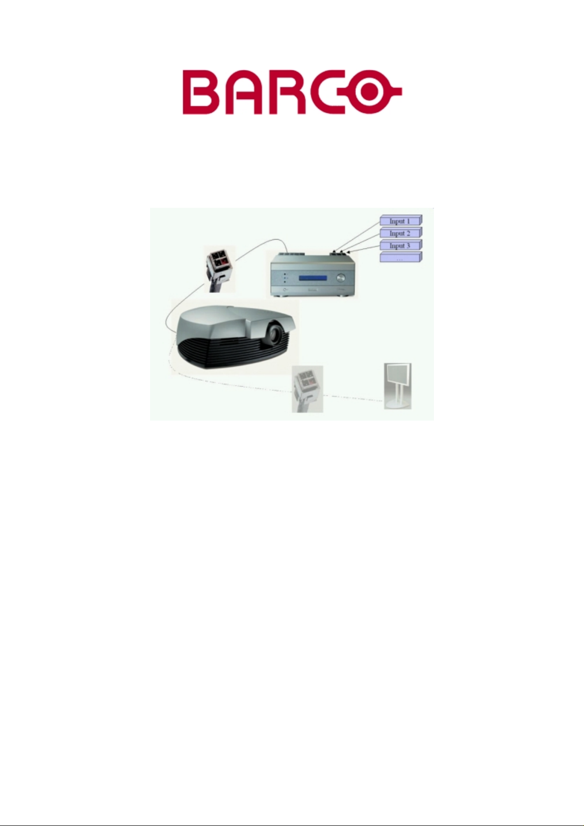
2.2 Overview of the System
Source managing
The Cine VERSUM system allows you to manage your sources in an e asy and comfortable way. As the Cine VERSUM Master c an
be stored close to your sources, signal loss is limited as m uch a s pos sible. Once the signal is processed, in a completely digital
way, the high-bandwidth cable allows for non-comp
romise distribution.
Image 2-1
Source connection
Display linking
Given this one-cable design, we int
VERSUM Master can feed a combination of up to 32 projectors (Cine VERSUM 80) and plasma displays (Cine VERS UM 50).
R5976490 CINE VERS UM SYSTEM 17012003
egrated the possibility of chaining multiple display units, one after another. As such, your Cine
5
Page 10
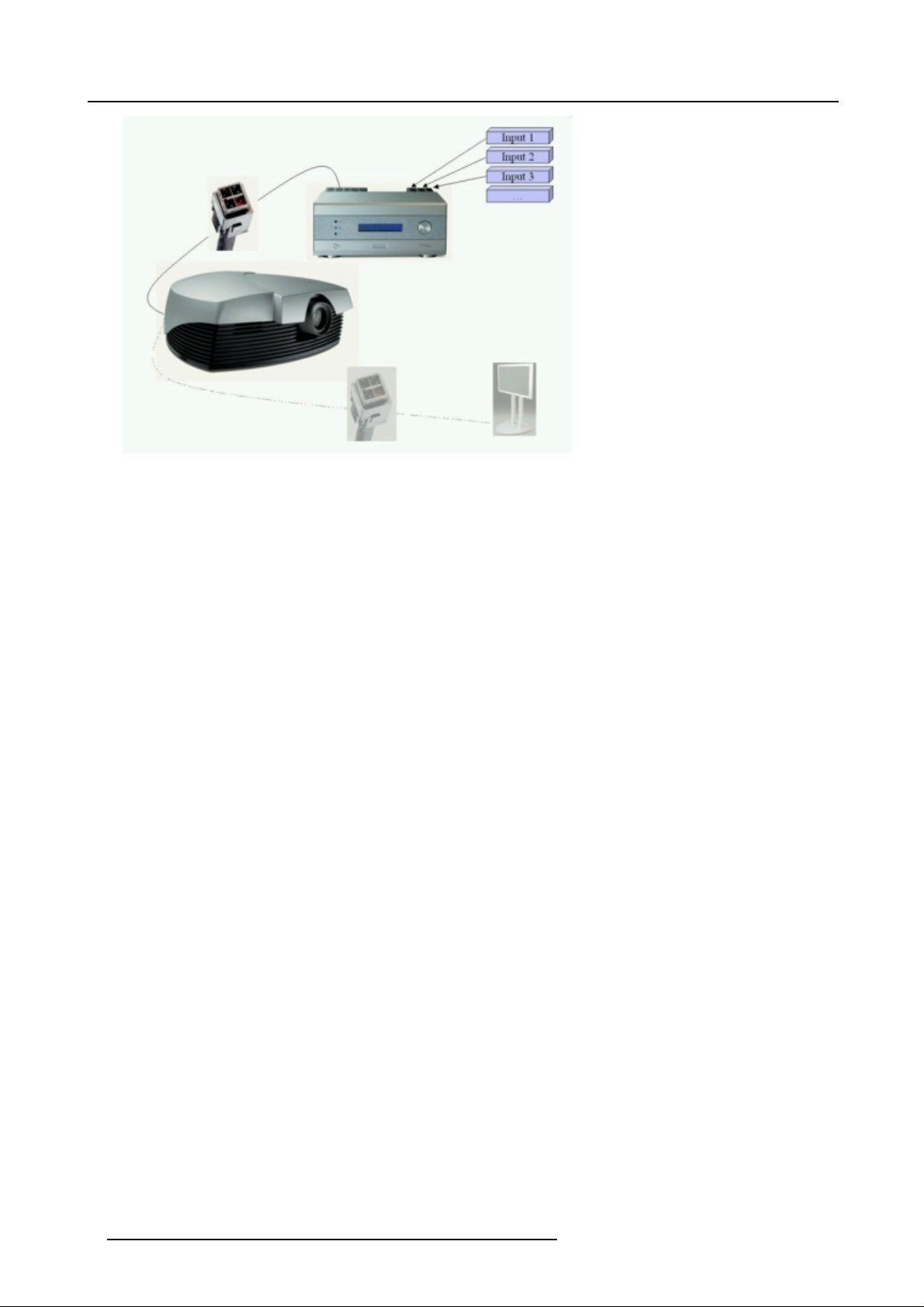
2. SYSTEM CONFIGURATION
Image 2-2
Display link
6 R5976490 CINE VERSUM SYSTEM 17012003
Page 11

3. OVERVIEW USER’S CONTROLS
Overview
• Cine VERSUM Master
• Cine VERSUM 80
• Cine VERSUM 50
• Remote Control
• Remote Control operation
3.1 Cine VERSUM Master
Front View
The front side of theCine VERSUM Master is provided with the following controls:
3. OVERVIEW USER’s CONTROLS
Image 3-1
Front side Cine VERSUM Mast er
Controls function description
Ref.
1 Infra Red Reception LED indicator Lights up when a valid Infra Red signal from the Remote Control has
2 Infra Red Receiver Reception diode for the Infra Red signals sent by the Remote Control
3 Standby LE D Blinks w hen the Cine VERSUM Master has been powered down to
4 Main power switch (see SWITCHING ON/OFF THE CINE VERSUM SYSTEM, page 15)
5 LCD Display This display indicates the status of the C ine VERSUM Master and allows
6 Selection and Confirmation dial The knob allows to navigate through the different menus.
Table 3-1
Function Description
been captured.
when a k ey is pressed.
Standby or Economy Standby mode.
you to navigate through the different menus.
3.2 Cine VERSUM 80
Top View
p side of the Cine VERSUM 80 is provided with the following controls:
The to
R5976490 CINE VERS UM SYSTEM 17012003
7
Page 12

3. OVERVIEW USER’s CONTROLS
Image 3-2
Cine V ERSUM 80 controls
Controls function description
Function Description
Ref.
1 Infra Red Receiver Reception diode for the IR signals from the Remote Control. Allows
2 Infra Red Reception LED indicator Lights up when a valid IR signal from the Rem ote Control has been
3 Standby LE D Lights up continuously: projector in the operation mode.
4 Main power switch Button pressed, s witches the projector in the ’Standby’ mode. This mode
Table 3-2
switching On/Off (Standby) of the projector separately and controlling
theCineVERSUMMaster.
captured.
Lights up repeatedly 2 times sh ort, 1 time long: projector in the standby
mode
Blinks fast: projector in the cooling down mode after switching of
(duration 1 min.).
Lights up repeatedly 1 time long, 1 time short: projector has been started
up in the cooling down mode, waiting for lamp ignition.
is indicated by the standby LED which lights up repeatedly 2 times short,
1 time long.
3.3 Cine VERSUM 50
Rear and Front view
The only hard ware control on the Cine V ERS UM 50 is the Main Power Sw itch (1), located at the backside of the screen itself. This
switch puts the Screen in the ’OFF’ or Standby position ’ON’. From the Standby position, the operation is controlled by the Cine
SUM Master.
VER
The status of the Plasma screen is indicated by a blue LED (3), located at the bottom on the right of the screen. In the sa me corner
an IR LED (2) is mounted .
f
8
R5976490 CINE VERSUM SYSTEM 17012003
Page 13

Image 3-3
Cine V ERSUM 50 controls
Controls function description
Function Description
Ref.
3. OVERVIEW USER’s CONTROLS
1 Main Power Switch Switches the Cine VERSUM 50 in the S tandby mode. Operation mode is controlled
2 Infra Red Receiver Reception diode for the IR signals from the Remote Control to control the Cine
3 Standby LED Indicates the status of the Cine VERSUM 50, lights up in s tandby and operation
Table 3-3
by the Cine VERSUM Mas ter.
VERSUM Master.
mode.
3.4 Remote Control
Top side
The Infra Red Remote Control buttons support the following functionality:
R5976490 CINE VERS UM SYSTEM 17012003
9
Page 14

3. OVERVIEW USER’s CONTROLS
Image 3-4
Remote Control
Controls function description
Function Description
Ref.
1 Address button To match the Remote Control w ith the unit that you are addressing (number between
0 and 9).
2 Standby button To power up/down the Cine VERSUM Master and the displays in the link.
3 Digit buttons Allows to directly select sources.
4 RC operation indication Lights up w hen a button on the remote control is pressed (Visual indication of remote
control operation – Battery check).
5 TEXT Press to remove bar scale display when adjusting picture. Press button again for
reactivation.
6 FREEZE Press to freeze the image
7 Picture controls Allow to optimize the picture rep roduction
Table 3-4
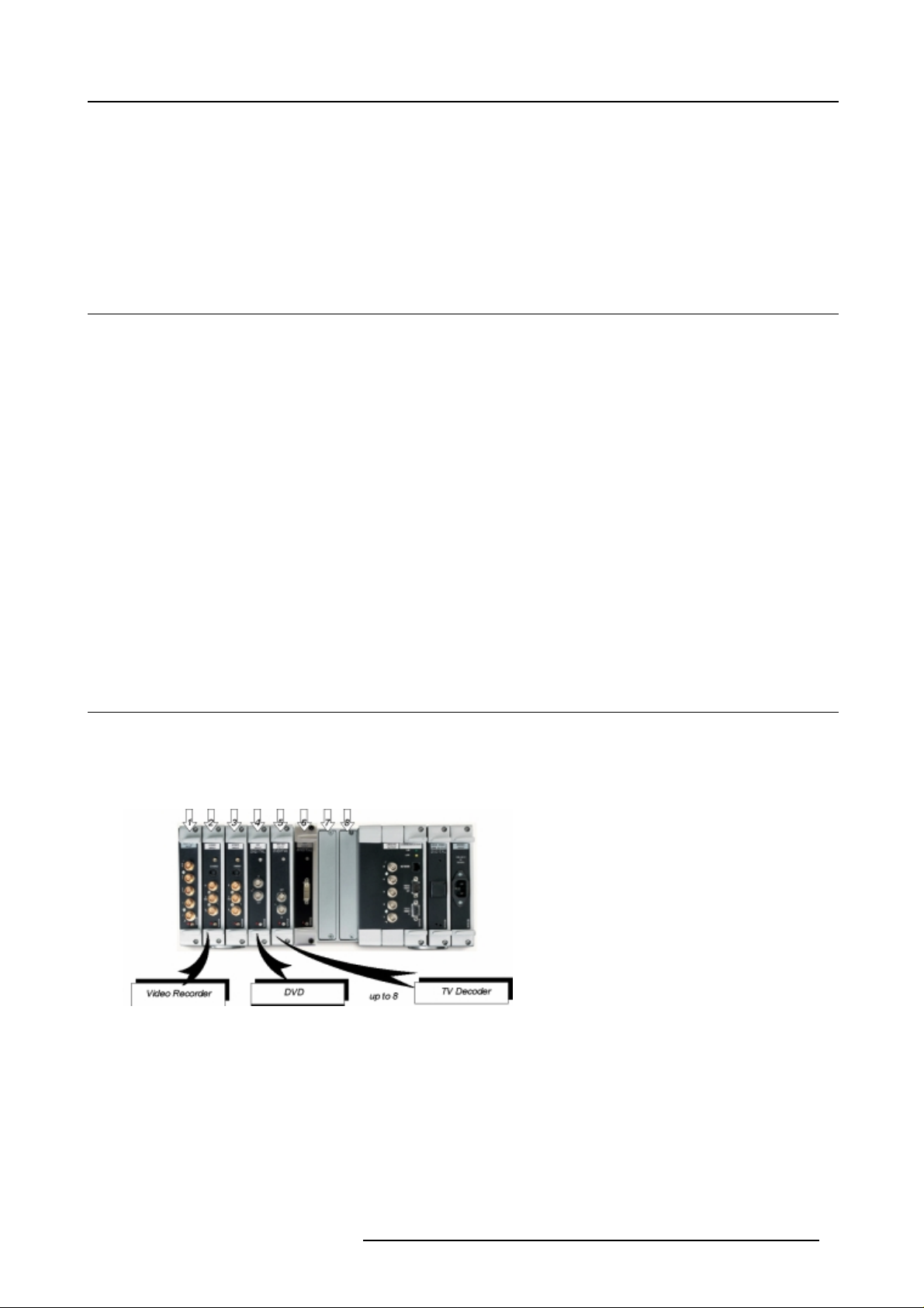
Stored sources
The Cine VERSUM Master can be equippedwith up to 8 digital and analog input modules. T hese modules are linked to your sources
and can be selected with the touch of a bu tton on the Remote Control.
The table below allows you to note the stored source per input slot, digit button 1 to 8.
Digit Button
Stored source
1
2
3
10 R5976490 CINE VERSUM SYSTEM 17012003
Page 15

3. OVERVIEW USER’s CONTROLS
Digit Button
4
5
6
7
8
Stored source
3.5 Remote Control operation
Overview
• General
• Battery Insertion in the Remote Control
• Visualization of comman ds
3.5.1 General
How to use
The Remote Control allows you to control your Cine VERSUM Master, even when it is built into a cabinet. Indeed, the S L/XL cable
allows for 2–way communication. T his means you can point the Remote Control to a display unit and still change the settings of the
Cine V ERSUM Master.
Image 3-5
Master control via 2–way communication SL/XL cable
Backlighting
When a button on the remote control is pressed, backlight is activated automa tically. That allows the user to operate the remote
control in a dark room. Backlight is turned off automatically a few seconds after the last button activation.
If backlight and RC operation indicator lights up too long or continuously, batteries need to be replaced.
R5976490 CINE VERS UM SYSTEM 17012003 11
Page 16

3. OVERVIEW USER’s CONTROLS
Factory address setting of the modules
The factory address setting of the m odules is as follows:
Module Individual Address
Common Address
Cine VERSUM 80 address <9> no co mm on address
Cine VERSUM 50 address <9> no co mm on address
Cine VERSUM Master address <1> comm on address <0>
Common add ress: is a fixed address, stored in the module. The module will execute the commands sent by
a Remote Control, programmed with the
common address <0>.
3.5.2 Battery Insertion in the Remote Control
Where to find the batteries
The batteries are not placed in the remote control to avoid remote control operation in its package, resulting in a shorter battery life
time.
How to install the batteries
1. P ush the cover tab (A) with the fingernail a little backwards and pull upwards the cover top (B). (image 3-6)
2. S lide the cover forwards to remove. (image 3-7)
3. P ush the battery body towards the spring and lift it up to remove. (image 3-8)
4. Insert two AA size batteries, mak ing sure the polarities match the + and – marks inside the battery compartment (ima ge 3-8).
5. Insert the lower tab of the b at
(image 3-8).
tery cover in the gap at the bottom of the rem ote control, and press the cover until it clicks in place
Image 3-7
Battery co ve r rem o val
Image 3-6
Battery cov
Image 3-8
Battery removal
er unlock
12 R5976490 CINE VERSUM SYSTEM 17012003
Page 17

3. OVERVIEW USER’s CONTROLS
How to reinstall the address
By r emoving the batteries, the address in the Remote Control will be set to 0. In case the different modules are controlled separately
(own address), the respective address of the module you desire to control has to be set. To reinstall an address, follow procedure
below:
1. P oint the Remote Control to the module o f w hich you want to know the address and press the address button (use a pencil).
(image 3-9)
On the screen appears a message box (image 3-10) indicating the address number. In the graphical display of the Cine VERSUM
Master appears the same m essage (image 3-11).
2. To adapt the address in the Remote Control, cover the IR transmitting diodes and press the address button once, followed within
the 5 seconds by pressing the c orresponding digit button, 1 to 8.
Image 3-9
Image 3-11
Message address display master
Image 3-10
Message address on-screen
3.5.3 Visualization of commands
How the commands are visualized
When a button on the Remote Control or the dial knob on the Cine VERSUM Master is pressed, the command is visualized on the
screen of the plasma display or of the projector and also on the graphical display of the Cine VERSUM Master. This c an take the
form of a menu, a m essage or a bar sc ale. Below an illustration of each item:
Image 3-13
Main menu on Master display
Image 3-12
On-screen main menu
R5976490 CINE VERS UM SYSTEM 17012003 13
Page 18

3. OVERVIEW USER’s CONTROLS
Image 3-14
On-screen message
Image 3-15
Message on Master display
Image 3-17
Bar scale o n Maste r display
Image 3-16
On-screen bar scale
14 R5976490 CINE VERSUM SYSTEM 17012003
Page 19

4. SWITCHING ON/OFF THE CINE VERSUM SYSTEM
4. SWITCHING ON/OFF THE CINE VERSUM SYSTEM
Overview
• Brief introduction
• Upon first startup
• Switching the system between OPERATION and STANDBY
• Switching the system between STANDBY and ECONOMIC Standby
• Switching the system OFF completely and BACK to Operation mode
• Turning ON the system from total OFF mode
4.1 Brief introduction
About the handled system in this manual
The Cine VERSUM is a modular system that provides you t he possibility to connect more than one display device to the Cine
VERSUM Master.
In this owner’s manual, we only discuss the most com mon case : one Master linked to one Projector. For info on the m ore complex
systems, please review the installation manual.
This is the chapter’s structure:
• Upon first startup
• Switching the system between OPERATION mode and STANDBY
• Switching the system between S TANDBY and ECO NO M IC STANDBY
• Switching the system OFF completely and BA CK TO OPERATION mode.
4.2 Upon first startup
Required steps
There are two steps upon first startup:
1. P ress the power switch (A) on the Cine VERSUM Master. (image 4-1)
The Cine VERSUM Master goes from OFF to STANDBY, visualized by blinking of the standby indicator
2. P ress the power switch (A) on the Cine VERSUM 80. (image 4-2)
The Cine VERSUM 80 goes from OFF to STANDBY, visualized by blinking of the standby indicator
3. S elect “Power up” in the menu on the Cine VERSUM Master, using the jog dial. (image 4-3, imag e 4-4)
The Cine VERSUM Master a nd th e Cine VERSUM 80 go from STANDBY to operation, visualized by lighting up of the proper
standby indicator
Image 4-1
Cine VERSUM Master
(B).
(B).
(B).
R5976490 CINE VERS UM SYSTEM 17012003 15
Page 20

4. SWITCHING ON/OFF THE CINE VERSUM SYSTEM
Image 4-2
Cine VERSUM 80
Image 4-4
Power up selection
Image 4-3
Cine VERSUM Master jog dial
4.3 Switching the system between OPERATION and STANDBY
Overview
• From OPERATION mode to STANDBY mode
• From STANDBY mode to OPERATION mode
4.3.1 From OPERATION mode to STANDBY mode
Using the Jog dial on the Cine VERSUM Master
1. P ress the jog dial once to enter the main menu. (image 4-5)
2. R otate the jog dial until “Shut down” in the menu is pointed to. (image 4-6)
3. P ress jog dial to activate the Shutdown selection.
The Cine VERSUM Master and the Cine VERSUM 80 go from O PERATION to STANDBY. During the power down process, a
power down message appears on-screen and on the Master display. At the end, the Master displays the enter menu screen.
(image 4-7, image 4-8)
Image 4-5
Main menu
Image 4-6
Shutdown selection
Image 4-7
Power down message
Image 4-8
Enter menu screen
16 R5976490 CINE VERSUM SYSTEM 17012003
Page 21

4. SWITCHING ON/OFF THE CINE VERSUM SYSTEM
Using the Remote Control
1. P oint the R emote Control to the front of the Cine VERSUM Master or to the Cine VERSUM 80.
2. P ress the standby button
TheCineVERSUMMasterandtheCineVERSUM80gofromOPERATIONtoSTANDBY.
Image 4-9
. (image 4-9)
4.3.2 From STANDBY mode to OPERATION mode
Using the Jog dial on the Cine VERSUM Master
1. R otate the jog dial until “Power up” in the menu o n the Cine V ERSUM Maste
2. P ress jog dial to activate the selection.
The Cine VERSUM M aster and the Cine VERSUM 80 go from STANDBY to OPERATION, display ing the last selected source.
r is pointed.
Using the Remote Control
1. P oint the R emote Control to the front of the Cine VERSUM Master or to the Cine VERSUM 80.
2. P ress the standby button
The Cine VERSUM M aster and the Cine VERSUM 80 go from STANDBY to OPERATION, display ing the last selected source.
.
4.4 Switching the system between STANDBY and ECONOMIC Standby
Overview
• From STANDBY mode to Economic STANDBY
• From Economic STANDBY mode to STANDBY
4.4.1 From STANDBY mode to Economic STANDBY
Using the Jog dial on the Cine VERSUM Master
1. P ress the jog dial onc e to enter the Powe r up menu. (image
2. R otate the jog dial until “Economic” in the menu on the Cine VERSUM Master is pointed to. (image 4-11)
3. P ress jog dial to activate the selection
The Cine VERSUM Master and the Cine VERSUM 80 go from STANDBY to Economic STANDBY. The economic standby is
visualized in the Mas ter display with a Zzzzz-message with turned off backlighting. (image 4-12)
4-10)
Image 4-10
Power up m enu
R5976490 CINE VERS UM SYSTEM 17012003 17
Image 4-11
Economic menu
Page 22

4. SWITCHING ON/OFF THE CINE VERSUM SYSTEM
Image 4-12
Economic standby
Using the Remote Control
1. P oint the Remote Control to the front of the Cine VER SUM Master or to the Cine VERSUM 80
2. Toggle with the ↑ or ↓ arrow keys until “Economic” in the menu on the Cine VERSUM Master is pointed to (image 4-11).
3. P ress ENT ER to activate selectio n.
The Cine VERSUM Master and the Cine VERSUM 80 go from STANDBY to Economic STANDBY. The economic standby is
visualized in the Mas ter display with a Zzzzz-message with turned off backlighting (image 4-12).
4.4.2 From Economic STANDBY mode to STANDBY
Awaking the Cine VERSUM Master from the economic standby m ode is only possible with the jog dial.
How to awake the Cine VERSUM Master
1. P ress the jog dial once.
The Cine VERSUM Master and the Cine VER SUM 80 g o from Econom ic STANDBY to STANDBY. (image 4-13, image 4-14)
2. S witching to operation mode, see From S TANDBY m ode to OPERATION mode, page 17.
Image 4-13
Economic standby
Image 4-14
Standby screen
4.5 Switching the system OFF completely and BACK to Operation m ode
Overview
• Turning OFF the system from Operation mode
4.5.1 Turning OFF the system from Operation mode
How to turn OFF the system totally
1. First, switch the system in the standby mode (see From OPERATION mode to STANDBY mode, page 16).
2. P ress the power switch on the Cine VERSUM 80 (image 4-2).
The Cine VERSUM 80 goes from standby to OF F.
3. P ress the power switch on the Cine VERSUM Master (image 4-1).
The Cine VE RSUM Master goes from standby to OFF.
18
R5976490 CINE VERSUM SYSTEM 17012003
Page 23

4. SWITCHING ON/OFF THE CINE VERSUM SYSTEM
4.6 Turning ON the system from total OFF mode
How to turn ON the system back to Operation mode
1. P ress the power switch on the Cine VERSUM Master (image 4-1).
The C ine VERSUM Mas ter goes from OFF to standby. (image 4-15)
2. P ress the power switch on the Cine VERSUM 80 (image 4-2).
The Cine VERSUM 80 goes from OFF to standby.
3. Turning on to operation m ode, see From S TANDBY m ode to OPERATION mode, page 17.
Image 4-15
R5976490 CINE VERS UM SYSTEM 17012003 19
Page 24

4. SWITCHING ON/OFF THE CINE VERSUM SYSTEM
20 R5976490 CINE VERSUM SYSTEM 17012003
Page 25

5. DIRECT SOU RCE SELECTION
5.1 From standby mode
Using the digit buttons on the Remote Control
1. M ake sure that the connected sources to the Cine VERSUM Master are turned on.
2. U sing the digit button on the Rem ote Control, key in the corresponding slot number (from 1 to 8). (image 5-1)
The Cine VERSUM Master powers up and starts on its turn powering up the connected displays. Image of the selected source
appears on the display.
5. Direct source selection
Image 5-1
Digit buttons on Remote Control
Using the standby button on the Remote Control
1. M ake sure that the connected sources to the
2. U sing the standby button
The Cine VERSUM Master powers up and starts on its turn powering up the connected display. The image of the last selected
source will be redisplayed on the connected dipslay.
Image 5-2
Standby button on Remote Control
on the Remote C o ntrol, press the standby button. (image 5-2)
Cine VE RSUM Master are turned on.
R5976490 CINE VERS UM SYSTEM 17012003 21
Page 26

5. Direct source selection
5.2 Return to standby mode
How to return to standby remotely
1. P oint the Remote Control to the front of the Cine VERSUM Master or the Cine VERSUM 80.
2. P ress the standby button on the Remote Control again. (image 5-2)
The Cine VERSUM Master switches to the standby mode and switches on its t urn the connected display into the standby mode.
When switching the Cine VERSUM 80 into the standby mode, a cool down period for the lamp of about 1
minute is activated. As a result, restarting of the lamp is not possible during the cool down period. This mod e
is indicated by the standby LED which blinks at a beat of 0.3 on/0.3 off
22 R5976490 CINE VERSUM SYSTEM 17012003
Page 27

6. IMAGE CONTROL
6. IMAGE CONTROL
Image controls
The Brightness, Contrast, Sharpness (Detail), Color and Tint functions are directly accessible with the Remote Control.
The adjustment functions, when selected, display a slide bar overlayed on the source image.
It is useful to adjust the Brightness, when ever the ambient room lightning changes. The same is true for
Contrast. Please no te that for the best result, it is advised to first change the B rightness, then the Contrast.
6.1 Brightness Control
How to adjust the Brightness
The Brightness function is used to adjust the overall light output. To adjust the Brightness, press the (+) or (-) side of the button
’BRIGHT’ (image 6-1.
The following barscale is overlayed on the source image,image 6-2.
Press the (+) button for a brightener image or the (- ) button for a darker image.
If video or data is displayed with a black background, adjust until the background just appears (black becomes a very dark grey).
Image 6-2
Image 6-1
6.2 Contrast Control
How to adjust the Contrast
The Contrast function is us ed to adjust the co ntrast between the light and dark areas of the displayed image.
To adjust Contrast, press the (+) or (-) side of the button ’CONTR’ (image 6-3). The following barscale is overlayed on the source
image, image 6-4.
Press the (+) or (-) button until dark parts o f the image show good detail.
If Contrast is set too high, the image loses detail and clarity. If set too low, it may be difficult to distinguish between foreground and
background information.
R5976490 CINE VERS UM SYSTEM 17012003
23
Page 28

6. IMAGE CONTROL
Image 6-3
Image 6-4
6.3 Sha
rpness (Detail) Control
ow to adjust the Sharpness
H
The Sharpness function is used to adjust the image sharpness of video signals when using a video decoder installed in the Cine
VERSUM Master.
To adjust the Sha rpness, press the (+) or (-) side of the bu tton ’SHARP’ (image 6-5). The following barscale is overlayed on the
source image,image 6-6.
Press the (+) or (-) button until the sharpest display is attained. Detail level should be r oughly proportional to the input signal quality.
Higher levels of detail improve good quality levels. Low levels of detail reduce noise in poor quality signals.
Image 6-6
Image 6-5
24 R5976490 CINE VERSUM SYSTEM 17012003
Page 29

6. IMAGE CONTROL
6.4 Color (Saturation) Control
How to adjust the Color (Saturation)
The Color function is used to adjust color saturation levels and is only a ctive for Video and S-Video sources.
Toadjust Color,press the (+) or (-) side of the button ’CO LOR’ (image 6-7). The following barscale is o verlayed on the source image,
image 6-8.
Press the (+) or (-) button until the desired color saturation level is displayed. If color is set to a 0% level, the result will be black and
white picture. If the color is set too high, the color levels in the image will be over-powering.
Image 6-8
Image 6-7
6.5 Tint control
HowtoadjustTint(Hue)
The Tint function is used to adjust color hue to obtain true color reproduction and is only active for Video and S-Video when using
the NTSC4.43 or NTSC 3.58 color system. For PAL and SECAM sources, Tint is not adjustable.
To adjus t Tint, press the (+) or (-) side of the button ’TINT’ (image 6-9). The following barscale is overlayed on the source image,image 6-10.
Press the (+) or (-) button un til an optimal display is obtained. It is best to adjust tint while displaying an image with natural flesh
tones.
R5976490 CINE VERS UM SYSTEM 17012003
25
Page 30

6. IMAGE CONTROL
Image 6-9
Image 6-10
26 R5976490 CINE VERSUM SYSTEM 17012003
Page 31

INDEX
Index
C
Cine VE RSUM 5
System configuration 5
Cine VERSUM System 15
Switching O n/Off the system 15
F
First startup 15
I
Image control 23–25
Brightness 23
Color (Saturation) 25
Contrast 23
Sharpness 24
Tint 25
Introduction 1 5
On/Off 15
L
Location of User controls 9
Location of User ’s controls 7–8
Cine VERSUM 50 8
Cine VERSUM 80 7
Cine VERSUM Master 7
O
On/Off 15
Introduction 15
R
Remote control 11–13
Battery insertion 12
General 11
Operation 11
Visualization of commands 13
Return 22
To standby 22
S
Safety instructions 3–4
Cine VER SUM Mas ter 4
Safety Instructions 3–4
Cine VE RSUM 50 4
Cine VE RSUM 80 3
General 3
Module related 3
Source 21
Direct selection 21
Source selection 21
From standby mode 21
Switching 16–19
Economic standby to standby 18
Off com pletely 18
Operation to standby 16
Standby to Economic standby 17
Standby to Operation 1 7
Standby/Economic standby 17
Turningontooperation 19
Switching system 16, 18
Off/Operation mode 18
Operation/Standby 16
System 5
Overview 5
U
User’s controls 7
Overview 7
V
Video distribution solution 5
R5976490 CINE VERS UM SYSTEM 17012003
27
 Loading...