

Page 1
BARCO PROJECTION SYSTEMS
Date:
070597
701 MULTIMEDIA
R9000740
OWNER'S MANUAL
Rev. :
01
VISION
Art. No.
R5975238
Page 2

Due to constant research, the information in this manual is subject to
change without notice.
Produced by BARCO NV, May 1997.
All rights reserved.
Trademarks are the rights of their respective owners.
Printed in Belgium
Page 3

TABLE OF CONTENTS
WARNINGS ........................................................................................................1-1
SAFETY INSTRUCTIONS................................................................................... 1-1
On safety ....................................................................................................1-4
On installation .............................................................................................1-5
On servicing ...............................................................................................1-6
On cleaning ................................................................................................1-6
On repacking ..............................................................................................1-7
On illumination ............................................................................................1-7
LOCATION AND FUNCTION OF CONTROLS ...................................................2-1
Rear panel terminology ..............................................................................2-2
Front panel terminology ..............................................................................2-3
Control panel terminology ...........................................................................2-4
a. The local keypad ....................................................................................2-4
b. RCU control panel terminology ...............................................................2-4
POWER (MAINS) CONNECTION .......................................................................3-1
Switching on/off ..........................................................................................3-2
Power (mains) cord connection ..................................................................3-2
SOURCE CONNECTIONS .................................................................................4-1
Signal input connection to the projector : ....................................................4-2
Connecting a Composite Video source. ......................................................4-3
Connecting a S-Video source. ....................................................................4-4
Connecting a RGB Analog source with composite sync. .............................4-5
Connecting a RGB Analog source with Tri-level sync. ................................4-7
Connecting a Component source................................................................4-8
Connecting a Component source with Tri-level sync. ..................................4-9
Connecting a computer, e.g. IBM PC (or compatible), Apple Macintosh to
the RS232 input of the projector. .............................................................. 4-11
Connecting a RCVDS 05 switcher to the projector. ..................................... 4-12
Connecting a VS05 switcher to the projector. ............................................. 4-12
Connecting an IR Remote Receiver to the projector .................................. 4-12
Peripheral equipment ................................................................................ 4-12
CONTROLLING..................................................................................................5-1
Battery installation in the RCU. ...................................................................5-2
How to use your RCU .................................................................................5-3
Projector address .......................................................................................5-5
How to display a projector address? ...........................................................5-5
How to program an address into the RCU? .................................................. 5-6
Input selection............................................................................................. 5-6
Picture controls ........................................................................................... 5-8
The Pause key. ......................................................................................... 5-11
START UP OF THE ADJUSTMENT MODE........................................................6-1
Entering the adjustment mode ....................................................................6-2
Adjustment mode .......................................................................................6-3
R5975238 BARCOVISION 701 MULTIMEDIA 070597
TABLE OF CONTENTS
1
Page 4

TABLE OF CONTENTS
GUIDED ADJUSTMENT MODE ..........................................................................7-1
Start up of the guided adjustment mode. ......................................................7-2
Overview flowchart 'Guided Adjustment' procedure. .....................................7-3
Selecting Setup Pattern ...............................................................................7-4
Internal Cross Hatch Pattern .......................................................................7-5
Picture tuning ..............................................................................................7-6
Sync Fast/Slow toggle .................................................................................7-6
Line Doubler (option) ...................................................................................7-6
Enhanced blue ON/OFF ..............................................................................7-7
Raster Centering on Green CRT Faceplate ..................................................7-8
Shifting Red and Blue on Green.................................................................7-10
Left-Right (East-West) Adjustments ...........................................................7-10
Vertical Centerline Bow Adjustment ........................................................... 7-11
Vertical Centerline Skew Adjustment.......................................................... 7-11
Right Keystone Adjustment ....................................................................... 7-12
Left Keystone Adjustment.......................................................................... 7-12
Right Bow Adjustment ...............................................................................7-12
Left Bow Adjustment .................................................................................7-13
Horizontal Size Adjustment........................................................................ 7-13
Top-Bottom (North-South) Adjustments...................................................... 7-14
Horizontal Centerline Skew Adjustment...................................................... 7-15
Horizontal Centerline Bow Adjustment .......................................................7-15
Top Keystone Adjustment.......................................................................... 7-15
Top Bow Adjustment ................................................................................. 7-16
Bottom Keystone Adjustment..................................................................... 7-16
Bottom Bow Adjustment ............................................................................ 7-16
Size-linearity Adjustment ........................................................................... 7-17
Vertical Linearity Adjustment ..................................................................... 7-17
Vertical Size Adjustment............................................................................ 7-18
Horizontal Phase Adjustment..................................................................... 7-19
Convergence Adjustment .......................................................................... 7-20
Blanking Adjustment.................................................................................. 7-21
Top blanking adjustment............................................................................ 7-22
Bottom blanking adjustment.......................................................................7-22
Left blanking adjustment ............................................................................ 7-23
Right blanking adjustment.......................................................................... 7-23
Color Balance ........................................................................................... 7-24
RANDOM ACCESS ADJUSTMENT MODE ....................................................... 8-1
TABLE OF CONTENTS
2
Starting up the random access adjustment mode. ..................................... 8-2
Overview flowchart 'Random Access Adjustment' mode ............................ 8-3
Selecting Setup Pattern ............................................................................. 8-5
Internal Cross Hatch Pattern ..................................................................... 8-6
Random Access Adjustment Mode Selection menu. .................................. 8-6
Picture tuning ............................................................................................ 8-7
Color Balance............................................................................................ 8-7
Sync Fast/Slow Adjustment .........................................................................8-8
Line doubler ................................................................................................8-9
Enhanced Blue On/Off Adjustment...............................................................8-9
Color Select .............................................................................................. 8-10
R5975238 BARCOVISION 701 MULTIMEDIA 070597
Page 5
TABLE OF CONTENTS
Geometry Adjustments .............................................................................. 8-11
Horizontal Phase Adjustment..................................................................... 8-12
Raster Shift Adjustment ............................................................................. 8-14
Left-Right (east-west) Adjustments ............................................................ 8-16
Top-Bottom (north-south) Adjustments.......................................................8-18
Horizontal Size Adjustment........................................................................ 8-20
Vertical Linearity Adjustment ..................................................................... 8-21
Vertical Size Adjustment............................................................................ 8-22
Blanking Adjustments ................................................................................ 8-23
Convergence Adjustments ........................................................................ 8-25
SERVICE MODE ................................................................................................9-1
Starting up the Service mode. ....................................................................9-2
Overview flowchart 'Service' mode............................................................... 9-3
Projector set up........................................................................................... 9-4
Identification ............................................................................................... 9-4
Total run time ..............................................................................................9-5
Change password .......................................................................................9-6
Change language ........................................................................................9-7
Change projector address ...........................................................................9-8
Change baudrate ........................................................................................9-8
Power up mode ...........................................................................................9-9
BARCO logo ............................................................................................. 9-10
Memory management................................................................................ 9-11
Copy a block............................................................................................. 9-11
Deletion of blocks...................................................................................... 9-12
Deleting block by block.............................................................................. 9-13
Deletion of all blocks ................................................................................. 9-14
All settings to midposition .......................................................................... 9-14
Undo all settings to midpos ........................................................................ 9-15
R & B convergence mid.............................................................................9-15
Undo R & B convergence mid.................................................................... 9-16
Switch green convergence off.................................................................... 9-16
Switch green convergence on.................................................................... 9-17
Common settings ......................................................................................9-17
G2 adjustment .......................................................................................... 9-18
CRT run in cycle ....................................................................................... 9-19
Projector warm up ..................................................................................... 9-20
I2C Diagnostics ........................................................................................ 9-21
MESSAGES, WARNINGS AND FAILURES.......................................................10-1
OPTIONS ......................................................................................................... 11-1
IR Receiver 800 .......................................................................................11-2
Hardwired RCU ........................................................................................ 11-2
Projector Control software ......................................................................... 11-3
RCVDS 05................................................................................................11-3
VS05 ........................................................................................................ 11-3
Adapter and communication cables ........................................................... 11-3
Ceiling mount CM50 .................................................................................. 11-4
R5975238 BARCOVISION 701 MULTIMEDIA 070597
TABLE OF CONTENTS
3
Page 6
TABLE OF CONTENTS
Orbiting Kit................................................................................................ 11-4
Soft edge matching kit ............................................................................... 11-4
Contrast modulation kit ..............................................................................11-4
Appendix A : Battery replacement in the RCU.................................................... A-1
Appendix B : Orbiting.......................................................................................... B-1
Appendix C : Soft edge matching ........................................................................ C-1
Appendix D : Contrast modulation (option)........................................................... D-1
Appendix E : Adjustment Blocks (memory blocks) ............................................... E-1
Appendix F : Source numbers 90 - 99 ................................................................. F-1
TABLE OF CONTENTS
4
R5975238 BARCOVISION 701 MULTIMEDIA 070597
Page 7
SAFETY INSTRUCTIONS
WARNINGS
SAFETY INSTRUCTIONS
on safety
on installation
on servicing
on cleaning
on repacking
on illumination
R5975238 BARCOVISION 701 MULTIMEDIA 070497
SAFETY INSTRUCTIONS
1-1
Page 8
SAFETY INSTRUCTIONS
Notice on Safety
This equipment is built in accordance with the requirements of the international safety
standards EN60950, UL 1950 and CSA C22.2 No.950, which are the safety standards
of information technology equipment including electrical business equipment.
These safety standards impose important requirements on the use of safety critical
components, materials and isolation, in order to protect the user or operator against
risk of electric shock and energy hazard, and having access to live parts.
Safety standards also impose limits to the internal and external temperature rises,
radiation levels, mechanical stability and strength, enclosure construction and protection against the risk of fire.
Simulated single fault condition testing ensures the safety of the equipment to the user
even when the equipment's normal operation fails.
1-2
SAFETY INSTRUCTIONS
INSTALLATION INSTRUCTIONS
Before operating this equipment please read this manual thoroughly, and
retain it for future reference.
Installation and preliminary adjustments should be performed by qualified
BARCO personnel or by authorized BARCO service dealers.
OWNER’S RECORD
The part number and serial number are located at the left side of the projector.
Record these numbers in the spaces provided below. Refer to them whenever you
call upon your BARCO dealer regarding this product.
PART NUMBER :
SER. NUMBER :
DEALER :
R5975238 BARCOVISION 701 MULTIMEDIA 070497
Page 9
SAFETY INSTRUCTIONS
The lightning flash with an arrowhead within a triangle is
intended to tell the user that parts inside this product may cause
a risk of electrical shock to persons.
The exclamation point within a triangle is intended to tell the user
that important operating and/or servicing instructions are included in the technical documentation for this equipment.
WARNING
TO PREVENT FIRE OR ELECTRICAL SHOCK HAZARD, DO
NOT EXPOSE THIS EQUIPMENT TO RAIN OR MOISTURE
FEDERAL COMMUNICATION COMMISSION (FCC STATEMENT)
This equipment has been tested and found to comply with the limits of a class A
digital device, pursuant to Part 15 of the FCC Rules. These limits are designed to
provide reasonable protection against harmful interference when the equipment is
operated in a commercial environment. This equipment generates, uses and can
radiate radio frequency energy and, if not installed and used in accordance with the
instruction manual, may cause harmful interference to radio communications.
Operation of this equipment in a residential area is likely to cause harmful
interference in which case the user will be required to correct the interference at his
own expense.
R5975238 BARCOVISION 701 MULTIMEDIA 070497
SAFETY INSTRUCTIONS
1-3
Page 10
SAFETY INSTRUCTIONS
* All the safety and operating instructions should be read before using this unit.
* The safety and operating instructions manual should be retained for future reference.
* All warnings on the equipment and in the documentation manuals should be adhered
to.
* All instructions for operating and use of this equipment must be followed precisely.
On safety
. This product should be operated from an AC power source
1
Operating AC power voltage of the projector:
SAFETY INSTRUCTIONS
BARCOVISION 701 MULTIMEDIA
Art.No. R9000740 (
The projector leaves the factory for 230 Vac. Consult your dealer to switch over to
120 Vac.
If you are not sure of the type of AC power available, consult your dealer or local
power company.
. This product is equipped with a 3-wire grounding plug, a plug having a third
2
(grounding) pin. This plug will only fit into a grounding-type power outlet. This is a
safety feature. If you are unable to insert the plug into the outlet, contact your electrician
to replace your obsolete outlet. Do not defeat the purpose of the grounding-type plug.
WARNING FOR THE CUSTOMERS
(EARTHED) via the supplied 3 conductor AC power cable.
(If the supplied power cable is not the correct one, consult your dealer.)
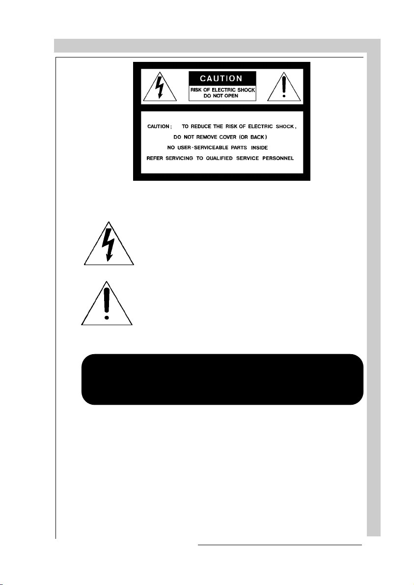
A. Mains lead (Power cord) with CEE 7 plug
The wires of the mains lead are colored in accordance with the following code.
230V AC
)
: THIS APPARATUS MUST BE GROUNDED
:
Green and yellow: earth (safety earth)
Blue: neutral
Brown: line (live)
1-4
R5975238 BARCOVISION 701 MULTIMEDIA 070497
Page 11
SAFETY INSTRUCTIONS
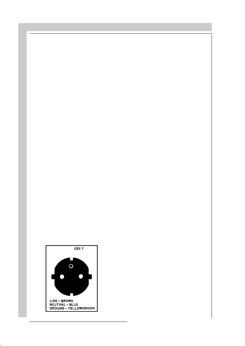
B. Power cord with ANSI 73.11 plug
. Do not allow anything to rest on the power cord. Do not locate this product where
3
persons will walk on the cord.
To disconnect the cord, pull it out by the plug. Never pull the cord itself.
. If an extension cord is used with this product, make sure that the total of the ampere
4
ratings on the products plugged into the extension cord does not exceed the
extension cord ampere rating. Also make sure that the total of all products plugged
into the wall outlet does not exceed 15 amperes.
Never push objects of any kind into this product through cabinet slots as they may
5.
touch dangerous voltage points or short out parts that could result in a risk of fire or
electrical shock.
Never spill liquid of any kind on the product. Should any liquid or solid object fall into
the cabinet, unplug the set and have it checked by qualified service personnel before
resuming operations.
:
The wires of the power cord are colored in accordance with the following code.
Green/yellow: ground
White: neutral
Black: line (live)
. Lightning - For added protection for this video product during a lightning storm, or
6
when it is left unattended and unused for long periods of time, unplug it from the wall
outlet. This will prevent damage to the projector due to lightning and AC power-line
surges.
On installation
. Do not place this equipment on an unstable cart, stand, or table. The product may
1
fall, causing serious damage to it.
. Do not use this equipment near water.
2
. Slots and openings in the cabinet and the back or bottom are provided for
3
ventilation; to ensure reliable operation of the product and to protect it from
overheating, these openings must not be blocked or covered. The openings should
never be blocked by placing the product on a bed, sofa, rug, or other similar surface.
R5975238 BARCOVISION 701 MULTIMEDIA 070497
SAFETY INSTRUCTIONS
1-5
Page 12

SAFETY INSTRUCTIONS
This product should never be placed near or over a radiator or heat register.
The projector should not be placed in a built-in installation or enclosure unless proper
ventilation is provided.
On servicing
Do not attempt to service this product yourself, as opening or removing covers may
expose you to dangerous voltage potentials and risk of electric shock!
Refer all servicing to qualified service personnel.
Unplug this product from the wall outlet and refer servicing to qualified service
personnel under the following conditions:
a. When the power cord or plug is damaged or frayed.
b. If liquid has been spilled into the equipment.
c.If the product has been exposed to rain or water.
d. If the product does not operate normally when the operating instructions are
followed.
Note : Adjust only those controls that are covered by the operating instructions since
improper adjustment of the other controls may result in damage and will often require
extensive work by a qualified technician to restore the product to normal operation.
e. If the product has been dropped or the cabinet has been damaged.
f. If the product exhibits a distinct change in performance, indicating a need for
service.
1-6
SAFETY INSTRUCTIONS
Replacement parts
technician has used original BARCO replacement parts or authorized replacement
parts which have the same characteristics as the BARCO original part. Unauthorized substitutions may result in degraded performance and reliability, fire, electric
shock or other hazards. Unauthorized substitutions may void warranty.
Safety check
service technician to perform safety checks to determine that the product is in proper
operating condition.
- When replacement parts are required, be sure the service
- Upon completion of any service or repairs to this projector, ask the
On cleaning
Unplug this product from the wall outlet before cleaning. Do not use liquid
cleaners or aerosol cleaners. Use a damp cloth for cleaning.
keep the cabinet looking brand-new, periodically clean it with a soft cloth. Stubborn
- To
stains may be removed with a cloth lightly dampened with mild detergent solution.
Never use strong solvents, such as thinner or benzine, or abrasive cleaners, since
these will damage the cabinet.
R5975238 BARCOVISION 701 MULTIMEDIA 070497
Page 13

SAFETY INSTRUCTIONS
- To ensure the highest optical performance and resolution, the projection lenses are
specially treated with an anti-reflective coating, therefore, avoid touching the lens.
To remove dust on the lens, use a soft dry cloth. Do not use a damp cloth, detergent
solution, or thinner.
On repacking
Save the original shipping carton and packing material; they will come in handy if you
ever have to ship your equipment. For maximum protection, repack your set as it was
originally packed at the factory.
On illumination
In order to obtain the best quality for the projected image, it is essential that the
ambient light which is allowed to fall on the screen be kept to an absolute minimum.
When installing the projector and screen, care must be taken to avoid exposure to
ambient light directly on the screen. Avoid adverse illumination on the screen from
direct sunlight or fluorescent lighting fixtures.
The use of controlled ambient lighting, such as incandescent spot light or a dimmer,
is recommended for proper room illumination. Where possible, care should also be
taken to ensure that the floors and walls of the room in which the projector is to be
installed are non-reflecting, dark surfaces. Brighter surfaces will tend to reflect and
diffuse the ambient light and hence reduce the contrast of the projected image on the
screen.
R5975238 BARCOVISION 701 MULTIMEDIA 070497
SAFETY INSTRUCTIONS
1-7
Page 14

SAFETY INSTRUCTIONS
1-8
SAFETY INSTRUCTIONS
R5975238 BARCOVISION 701 MULTIMEDIA 070497
Page 15

LOCATION AND FUNCTION OF CONTROLS
LOCATION AND FUNCTION OF CONTROLS
Rear Panel Terminology
Front Panel Terminology
RCU Terminology
R5975238 BARCOVISION 701 MULTIMEDIA 070497
LOCATION AND FUNCTION O F CONTROLS
2-1
Page 16
LOCATION AND FUNCTION OF CONTROLS
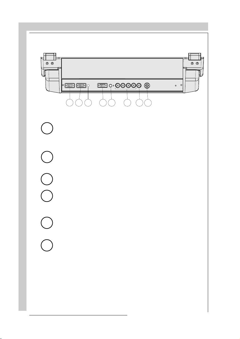
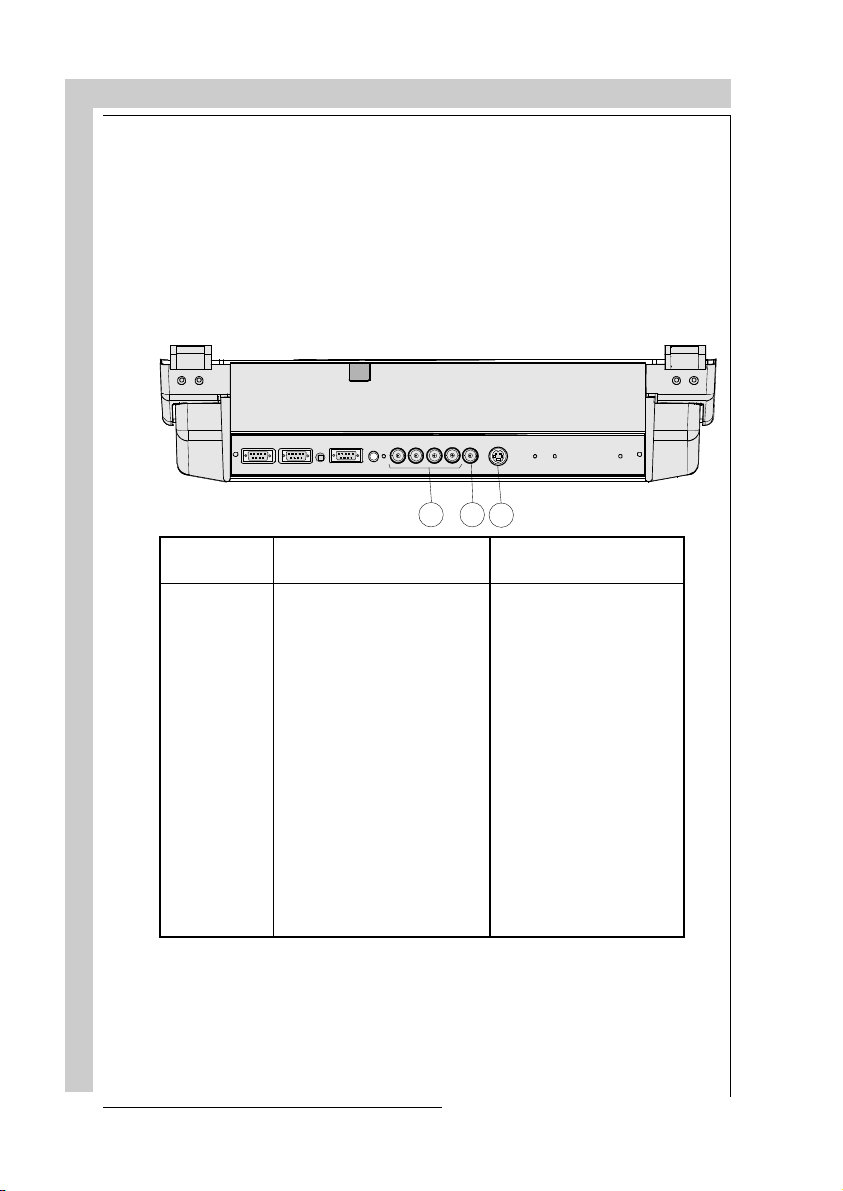
REAR PANEL TERMINOLOGY
LOCATION AND FUNCTION O F CONTROLS
RS232OUTRS232IN
1
2
RS232IN
1
Connection between the BARCOVISION 701 MULTIMEDIA and an IBM
COMM PORT
IR
(800 peripherals)
3
RG(S)B
REMOTE
R-Y
Y(S) B-Y
5
4
6 7
S-VID E O
S
VIDEO
8
PC (or compatible) or MAC (RS422) for remote computer control and data
communication.
RS232OUT
2
Used to connect to the next projector, RS232IN plug
(communication link for PC or MAC to the next projector)
IR sensor
3
receiver for control signals transmitted from the RCU.
Communication port (800 peripherals)
4
* allows communication between the RCVDS switcher and the projector.
* allows connection of a remote IR receiver unit to the projector.
* allows connection of an IRIS 800 to converge the image automatically.
IR Remote
5
remote input for wired remote control
RGB-S IN or (R-Y)Y(B-Y)-S IN (4x BNC connector)
6
RGB-S in
: allows a character generator, microcomputer, video camera,
:
etc. having analog RGB output to be connected to the projector.
2-2
Line inputs: - signals RED-GREEN-BLUE
- COMPOSITE sync. signal
(R-Y)Y(B-Y)-S IN
(component in):allows to connect e.g. a professional
VCR having component outputs to the projector.
Line inputs - signals RED-LUMA, LUMA, BLUE-LUMA
- COMPOSITE sync. signal
R5975238 BARCOVISION 701 MULTIMEDIA 070497
Page 17
LOCATION AND FUNCTION OF CONTROLS
7
8
VIDEO IN (Composite video, 1x BNC connector)
recorder, video camera, color receiver/monitor, etc. having video line
output to be connected to the projector.
S-VIDEO IN
for higher quality playback of Super VHS signals (4-pin S-VIDEO
connector).
: Separated Y/C (luma-chroma) signal inputs and outputs
FRONT PANEL TERMINOLOGY
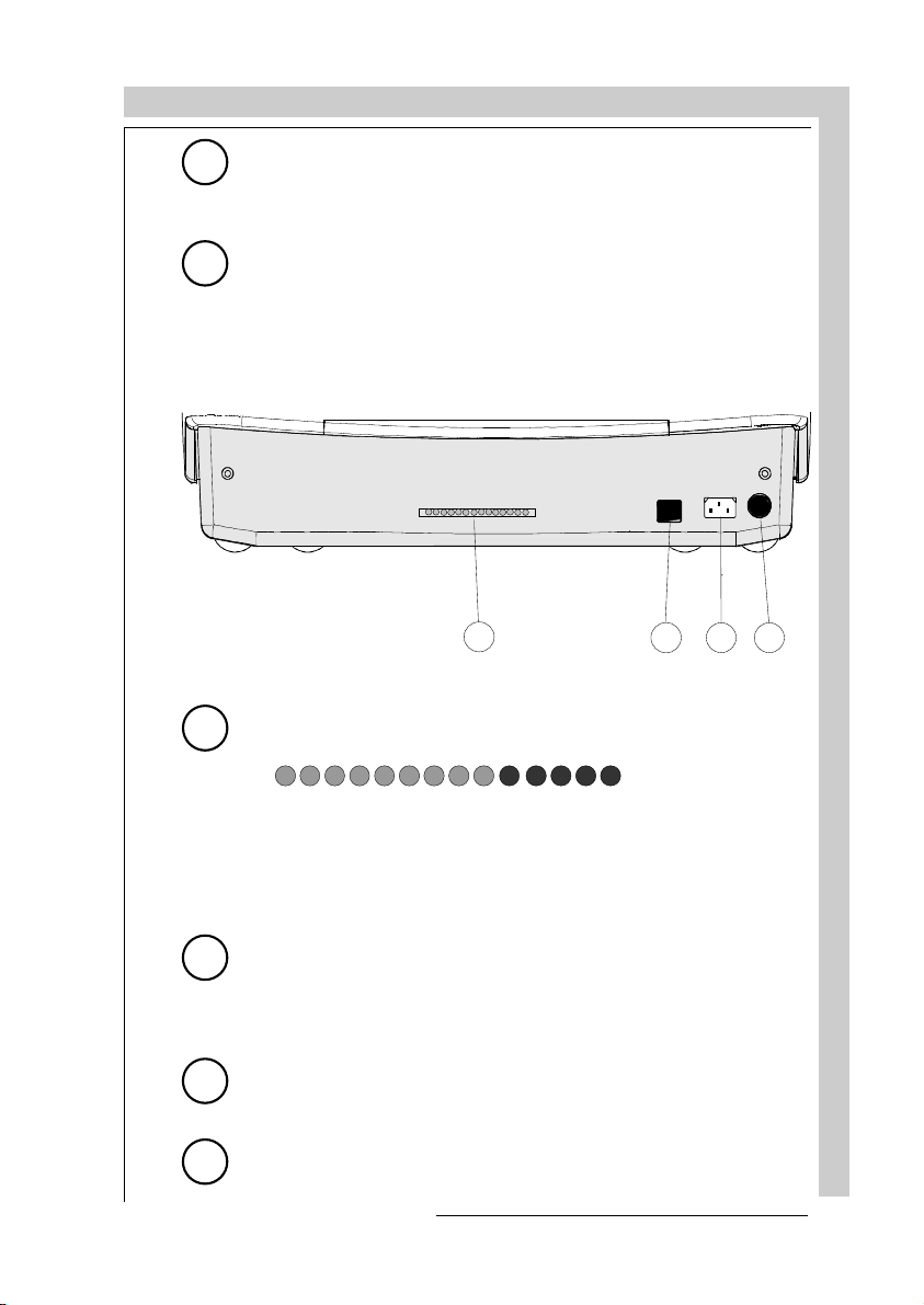
1
1
AUTODIAGNOSIS DISPLAY
LED indication for service purposes.
: allows a video tape
2
3
4
-CONV
+17V
+9V
POWER (MAINS) SWITCH
+210V
+30V
-9V
2
Depending on the hardware set-up of the projector during installation,
the projector switches to
standby, the standby led in the autodiagnosisdisplay lights up.
3
4
R5975238 BARCOVISION 701 MULTIMEDIA 070497
POWER (MAINS) INPUT
here and to wall the outlet.
IR SENSOR
receiver for control signals transmitted from the RCU700.
+CONV
: Connect the supplied ac power (mains) cord
HOLD DOWN EHT
: press the switch to turn the projector ON.
‘standby’
STANDBY
-17V
+HTHD
HOLD DOWN HD
SF
COINC
or to
‘operational mode’.
If in
LOCATION AND FUNCTION O F CONTROLS
2-3
Page 18
LOCATION AND FUNCTION OF CONTROLS
Control panel terminology
a. The local keypad
Getting access
The local keypad is covered by a door on
which the projector logo is screened.
ADJUST
EXIT
STANDBY
ENTER
To open this door, push as indicated on next drawing and turn it to the front side of
the projector.
b. RCU control panel terminology
LOCATION AND FUNCTION O F CONTROLS
2-4
This remote control includes a battery powered infrared (IR) transmitter that allows
the user to control the projector remotely.
This remote control is used for source selection, control, adaptation and set-up. It
includes automatic storing of :
- picture controls (Brightness, Sharpness,....)
- picture geometry adjustments
- convergence adjustments
Other functions of the remote control are:
- switching between standby and operational modes
- switching to "pause" (blanked picture, full power for immediate restarting)
- direct access to all connected sources
- variable adjustment speed : when pushing continuously on the arrow keys or the
picture keys, the adjustment will be executed in an accelerated fashion.
R5975238 BARCOVISION 701 MULTIMEDIA 070497
Page 19
LOCATION AND FUNCTION OF CONTROLS
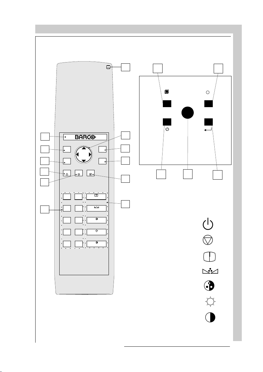
RCU Local keypad
12
1
2
ADJ
3
PAUSE8TEXT
4
STBY
EXIT
ENTER
11
10
9
2
ADJUST
STANDBY
4
11
10
EXIT
ENTER
9
5
+
-
0
9
6
7
5
3
SHARPNESS
+
-
8
TINT
+
-
6
COLOR
+
-
4
BRIGHTNESS
+
-
21
CONTRAST
7
stand-by
pause/park
32c
R5975238 BARCOVISION 701 MULTIMEDIA 070497
sharpness
tint
color
brightness
contrast
LOCATION AND FUNCTION O F CONTROLS
2-5
Page 20
LOCATION AND FUNCTION OF CONTROLS
LOCATION AND FUNCTION O F CONTROLS
1
2
3
4
5
6
7
8
9
10
11
Back light key
: adjust key, to enter or exit the adjustment mode.
ADJ.
Address key
0 and 9). Press the address key, followed by pressing one digit button
between 0 and 9.
: stand by button : - to initiate remote power up operation
STBY
Pause
power is retained for immediate restarting.
Digit buttons
Picture controls
'Controlling') for each picture function.
: when adjusting one of the image controls during a meeting, the
TEXT
displayed bar scale can be removed by pressing 'TEXT' key first. To redisplay the bar scale on the screen, press 'TEXT' key again. 'TEXT' key
is only active in operational mode. When 'TEXT' is off, no warning
message will be displayed.
ENTER
selection in the adjustment mode.
: to leave the adjustment mode or to scroll upwards when in the
EXIT
adjustment mode.
Control disk
Also allows to increment or decrement an adjustment in the adjustment
mode.
control disk up = up arrow in the menus
control disk down = down arrow in the menus
control disk to the right = arrow to the right on the menus
control disk to the left = arrow to the left on the menus
: when activated, all keys will be lit up and visible in the dark.
(sunk key), to enter the address of the projector (between
- to stop projection without main power off.
:to blank the image, press PAUSE. The image disappears but full
: direct input selection.
: use these buttons to obtain the desired level (see also
: to start up the adjustment mode or to confirm an adjustment or
: to make menu selections when in the adjustment mode.
2-6
12
RC operating indication
is pressed. (This is a visual indicator to check the operation of the remote
control)
: lights up when a button on the remote control
R5975238 BARCOVISION 701 MULTIMEDIA 070497
Page 21

POWER CONNECTION
POWER (MAINS) CONNECTION
R59 75456 BARCOVISION 701 MULTIMEDIA 070497
POWER CONNECTION
3-1
Page 22
POWER CONNECTION
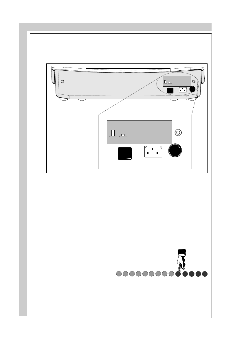
Power (mains) cord connection
Use the supplied power cord to connect your projector to the wall outlet. Plug the
female power connector into the male connector at the front of the projector.
See installati on ins tru ctions before
connecting to the s upply
ON
OFF
See installation instructions befor e
connecting to the sup ply
V NOM 120/230 Volt
I MAX 5/2.5 AMP
FREQ 60/50 Hz
ON
OFF
Switching on/off
The projector is switched ON and OFF using the power (mains) switch ON/OFF.
V NOM 120/2 30 Volt
I MAX 5 /2. 5 A MP
FREQ 60 /50 Hz
3-2
Pressed : ON
Not pressed : OFF
The projector can start now in the 'operational mode' (image displayed) or in the
'stand by mode', depending on the position of the 'power up' dip switch on the
controller unit. This DIP switch is set during installation by a qualified technician.
If you want to change this start up mode, call a qualified technician.
Stand by indication lamp :
no light up : projector in operational mode
red : projector is in stand by.
POWER CONNECTIO N
Leds on the front plate of the projector
-CONV
+17V
+9V
R5975238 BARCOVISION 701 MULTIMEDIA 070497
+210V
+30V
-9V
-17V
+CONV
+HTHD
STANDBY
SF
COINC
HOLD DOWN EHT
HOLD DOWN HD
Page 23

CONNECTIONS
SOURCE CONNECTIONS
- connecting a Video source
- connecting a S-Video source
- connecting a RGsB or RGBS analog source
- connecting a RG3sB or RGB3S analog source
- connecting a (R-Y)Ys(B-Y) or (R-Y)Y(B-Y)S analog source
- connecting a (R-Y)Y3s(B-Y) or (R-Y)Y(B-Y)3S analog source
PERIPHERAL EQUIPMENT CONNECTION
- Connecting a computer, e.g. IBM PC (or compatible), Apple
Macintosh to the RS232 input of the projector.
- connecting a RCVDS 05
- connecting a VSO5
- connecting an IR Remote Receiver
R5975238 BARCOVISION 701 MULTIMEDIA 280497
CONNECTIONS
4-1
Page 24
CONNECTIONS
Signal input connection to the projector :
- Composite Video (*)
- S-Video (*)
- RGBS or RGsB
- RGB3S or RG3sB
- (R-Y)Y(B-Y)S or (R-Y)Ys(B-Y) [component input] (**)
- (R-Y)Y(B-Y)3S or (R-Y)Y3s(B-Y) [component input] (**)
(*) If the line douoble feature is built in, this feature is available via a software on/off toggle.
(**) If the line double feature is built in, this feature is available for component video signals on standard
frequency via software on/off toggle.
4-2
CONNECTIONS
RS232 IN
RS232 OUT
COMM PORT
(800 peripherals)
REMOTE
RG(S)B
R-Y Y(S)
B-Y
3
S
VIDEO
1 2
S-VIDEO
Source No Projector input Press digit button
1 Comp. Video 1
2 S-Video* 2
3 RGBS or RGsB** 3
4 RGB3S or RG3sB*** 4
5 (R-Y)Y(B-Y)S or
(R-Y)Ys(B-Y)**** 5
6 (R-Y)Y(B-Y)3S or
(R-Y)Y3s(B-Y)***** 6
* Input signal Y/C (luma/chroma)
** Input signal : R, G and B with composite sync on G or separate composite
sync
*** Input signal : R, G and B with Tri level sync on G or separate Tri level sync.
**** Input signal : R-Y, Y and B-Y with composite sync on Y or separate
composite sync
***** Input signal : R-Y, Y and B-Y with Tri level sync on Y or separate Tri level
sync.
R5975238 BARCOVISION 701 MULTIMEDIA 280497
Page 25
CONNECTIONS
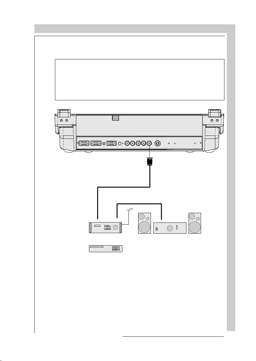
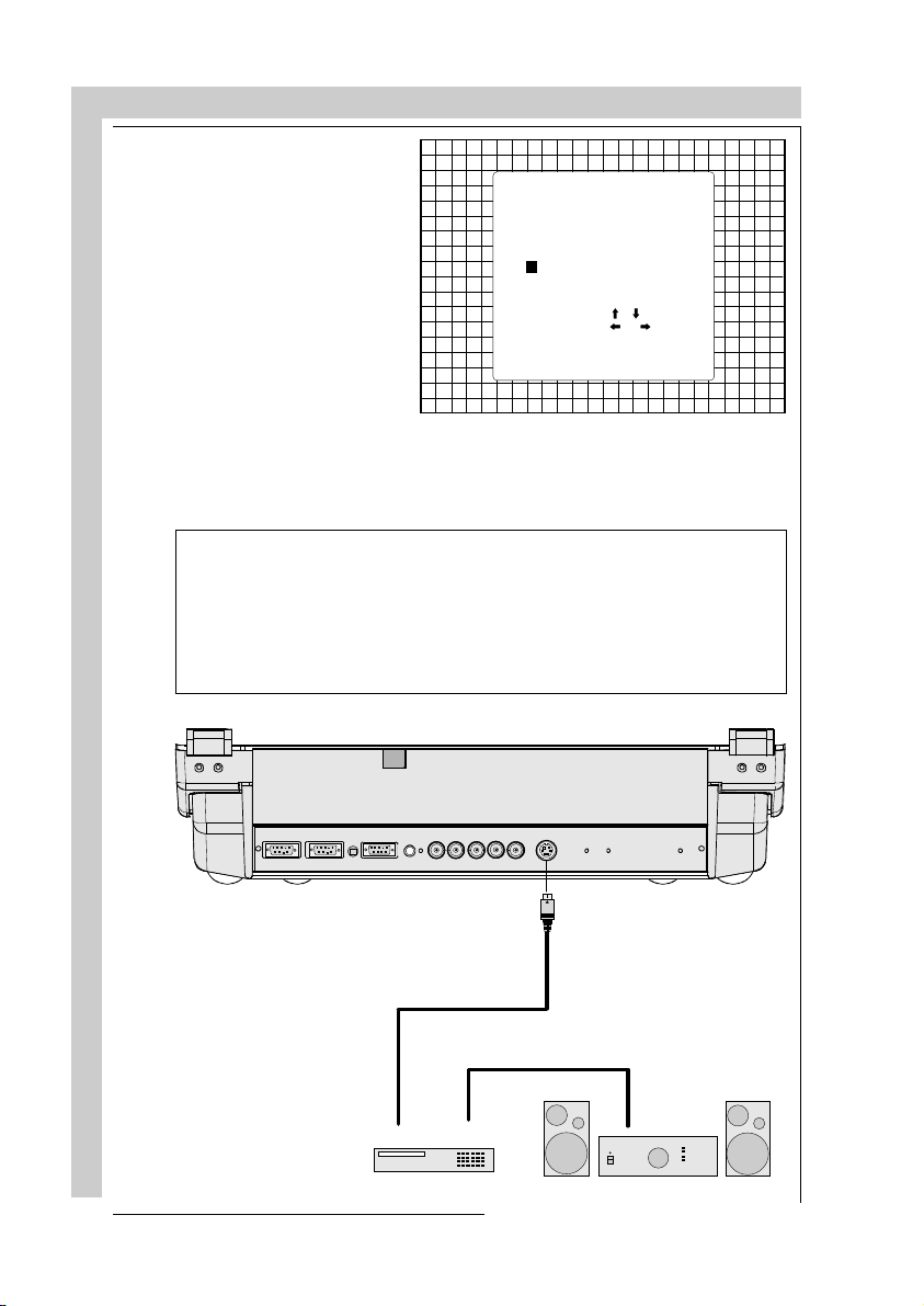
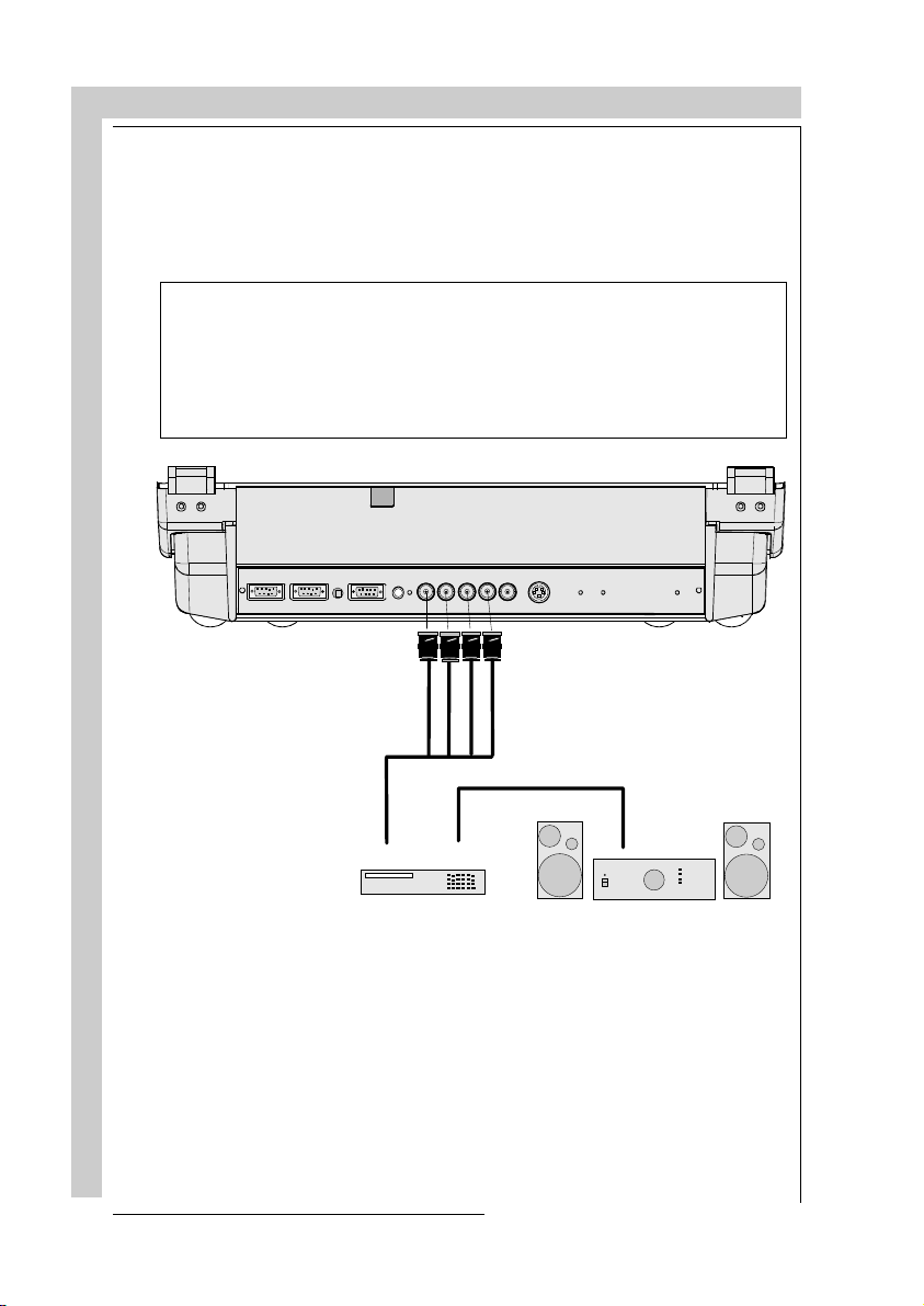
Connecting a Composite Video source.
Composite video signals from a VCR, OFF air signal decoder, etc..
If a line doubler is built in :
the default position of this line doubler is ON (active), the video input signal
will be displayed as a non interlaced image (= improved image stability).
To enable or to disable this line doubler function, enter the adjustment mode
and change the position of the ON/OFF toggle switch (see Picture tuning in
chapter 'Guided' adjustment mode or 'Random access' adjustment mode).
RS232 IN
(800 peripherals)
COMM PORT
RS232 OUT
TV tuner, e.g. TVDM40 stereo
REMOTE
RG(S)
R-Y
Y(S)
B
S-VIDEO
S
VIDEO
B-Y
Composite
video
Audio amplifier
VCR
Video input selection :
a. Press digit button 1 on the RCU or
b. with the local keypad :
(to gain access to the local keypad, see Local keypad in chapter Location and
function of control.)
- press
ADJUST
key, the General access menu is displayed on the screen.
CONNECTIONS
R5975238 BARCOVISION 701 MULTIMEDIA 280497
4-3
Page 26
CONNECTIONS
- use the control disk to highlight 1.
- press
ENTER
to select the
highlighted source.
GENERAL ACCESS
5 6
3 4
1 2
Enter ADJUST
Select with ,
or
then <ENTER>.
<EXIT> to return
SHARPNESS
BRIGHTNESS
CONTRAST
Connecting a S-Video source.
Separate Y-luma/C-chroma signals for higher quality playback of Super VHS
signals.
If a line doubler is built in :
the default position of this line doubler is ON (active), the video input signal
will be displayed as a non interlaced image (= improved image stability).
To enable or to disable this line doubler function, enter the adjustment mode
and change the position of the ON/OFF toggle switch (see Picture tuning in
chapter 'Guided' adjustment mode or 'Random access' adjustment mode).
TINT
COLOR
4-4
CONNECTIONS
RS232 IN
RS232 OUT
COMM PORT
REMOTE
(800 peripherals)
VCR S-VHS
RG(S)B
R-Y
Y(S)
Luma/Chroma
S-VIDEO
S
VIDEO
B-Y
Audio amp lifier
R5975238 BARCOVISION 701 MULTIMEDIA 280497
Page 27
CONNECTIONS
S-Video input selection
a. Press digit button 2 on the RCU or
b. with the local keypad :
(to gain access to the local keypad, see Local keypad in chapter Location and
functions of control.)
- Press
ADJUST
key, the General access menu is displayed on the screen.
- Use the control disk to
highlight 2.
- Press
ENTER
to select
the highlighted source.
GENER AL ACCE SS
5 6
3 4
1 2
Enter ADJUST
Select with ,
or
then <ENTER>.
<EXIT> to return
SHARPNESS
TINT
COLOR
BRIGHTNESS
CONTRAST
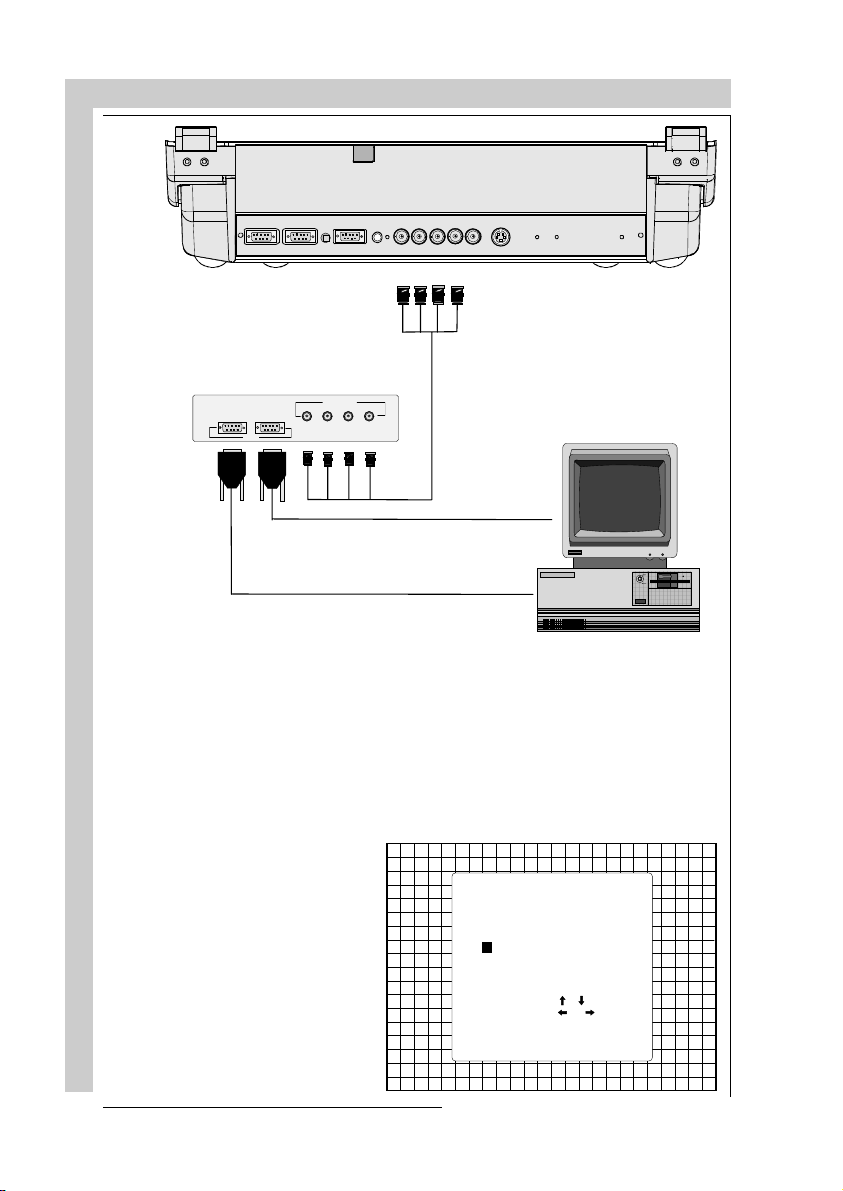
Connecting a RGB Analog source with composite sync.
RGB analog input terminals with composite sync input or with sync on green. The
projector detects automatically where the sync signal is located.
Always use an interface when a computer and local monitor have to be connected
to the projector. Examples of interfaces which can be applied :
Universal analog interface R9826100
RGB 120 MHz Analog Interface R9826570 (230V)
Multifunctional Analog Interface Kit R9828120 (230V)
(MAGIK) R9828129 (120V)
VGA interface R9828070 (230V)
MAC interface R9828050 (230V)
R5975238 BARCOVISION 701 MULTIMEDIA 280497
R9828079 (120V)
R9828059 (120V)
CONNECTIONS
4-5
Page 28
CONNECTIONS
CONNECTIONS
COMM PORT
RS232 OUT
R
(800 peripherals)
ANALOG O UT
G
RS232 IN
INPUT
REMOTE
BS
RG(S)B
R-Y
Y(S) B-Y
SVIDEO
S-VIDEO
RGBS or RGsB input selection
a. Press digit button 3 on the RCU or
b. With the local keypad :
(to gain access to the local keypad, see Local keypad in chapter Location and
functions of control.)
- Press
ADJUST
key, the General access menu is displayed on the screen.
- Use the control disk to high-
3.
light
- Press
ENTER
to select the
highlighted source.
GENER AL ACCE SS
5 6
3 4
1 2
Enter ADJUST
Select with ,
or
then <ENTER>.
<EXIT> to return
SHARPNESS
TINT
COLOR
BRIGHTNESS
CONTRAST
4-6
R5975238 BARCOVISION 701 MULTIMEDIA 280497
Page 29
CONNECTIONS
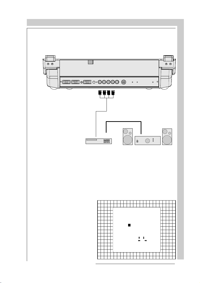
Connecting a RGB Analog source with Tri-level sync.
RGB analog input terminals with Tri level sync input or with Tri-level sync on green.
The projector detects automatically where the sync signal is located.
RS232 IN
RS232 OUT
COMM PORT
(800 peripherals)
RG(S)B
REMOTE
R-Y
Y(S)
VCR HDTV player
B-Y
SVIDEO
S-VIDEO
Audio amp lifier
RGB3S or RG3sB input selection
a. Press digit button 4 on the RCU or
b. With the local keypad :
(to gain access to the local keypad, see Local keypad in chapter Location and
functions of control.)
- Press
ADJUST
key, the General access menu is displayed on the screen.
- Use the control disk to high-
4.
light
- Press
ENTER
to select the
highlighted source.
GENER AL ACCE SS
5 6
3 4
1 2
Enter ADJUST
Select with ,
or
then <ENTER>.
<EXIT> to return
SHARPNESS
TINT
COLOR
BRIGHTNESS
CONTRAST
CONNECTIONS
R5975238 BARCOVISION 701 MULTIMEDIA 280497
4-7
Page 30
CONNECTIONS
Connecting a Component source.
(R-Y)Y(B-Y) analog input terminals with sync input or with sync on the luminance
(Y) input. The projector detects automatically where the sync signal is located.
Line doubling is possible for component video input sources on standard line
frequency.
If a line doubler is built in :
the default position of this line doubler is ON (active), the component video input
signal will be displayed as a non interlaced image (= improved image stability).
To enable or to disable this line doubler function, enter the adjustment mode and
change the position of the ON/OFF toggle switch (see Picture tuning in chapter
'Guided' adjustment mode or 'Random access' adjustment mode).
CONNECTIONS
RS232 IN
RS232 OUT
COMM PORT
(800 peripherals)
RG(S)B
REMOTE
R-Y
Y(S)
Professional VCR
B-Y
SVIDEO
S-VID E O
Audio amplifier
(R-Y)Y(B-Y)S or(R-Y)Ys(B-Y) input selection
a. Press digit button 5 on the RCU or
b. With the local keypad :
(to gain access to the local keypad, see Local keypad in chapter Location and
functions of control.)
- Press
ADJUST
key, the General access menu is displayed on the screen.
4-8
R5975238 BARCOVISION 701 MULTIMEDIA 280497
Page 31

CONNECTIONS
- Use the control disk to high-
5.
light
- Press
ENTER
to select the
GENERAL AC CESS
highlighted source.
5 6
3 4
1 2
Enter ADJUST
Select wi th ,
or
then <ENTER>.
<EXIT> to return
Connecting a Component source with Tri-level sync.
(R-Y)Y(B-Y) analog input terminals with Tri-level sync input or with Tri-level sync
on the luminance input.
SHARPNES S
TINT
COLOR
BRIGHTNE SS
CONTRAST
COMM PORT
RS232 IN
RS232 OUT
REMOTE
(800 peripherals)
Professional VCR
with Tri-level sync
R5975238 BARCOVISION 701 MULTIMEDIA 280497
RG(S)
R-Y
Y(S) B-Y
B
SVIDEO
S-VID EO
Audio amplifier
CONNECTIONS
4-9
Page 32

CONNECTIONS
(R-Y)Y(B-Y)3S or (R-Y)Y3s(B-Y) input selection
a. Press digit button 6 on the RCU or
b. With the local keypad :
(to gain access to the local keypad, see Local keypad in chapter Location and
functions of control.)
- Press
ADJUST
- Use the control disk to high-
6.
light
- Press
ENTER
highlighted source.
key, the General access menu is displayed on the screen.
to select the
GENERAL AC CESS
5 6
3 4
1 2
Enter ADJUST
Select wi th ,
or
then <ENTER>.
<EXIT> to return
SHARPNES S
TINT
COLOR
BRIGHTNE SS
CONTRAST
4-10
CONNECTIONS
R5975238 BARCOVISION 701 MULTIMEDIA 280497
Page 33

CONNECTIONS
Connecting a computer, e.g. IBM PC (or compatible), Apple
Macintosh to the RS232 input of the projector.
The projector has a RS232 port that allows it to communicate with a computer.
Applications: remote control and data communications.
a) remote control:
- easy adjustment of the projector via IBM PC (or compatible) or MAC connection.
- allow storage of multiple projector configurations and set ups.
- wide range of control possibilities.
- address range from 0 to 255.
b) data communications:
- sending data to the projector or copying the data from the projector to a hard
memory device.
COMM PORT
(800 peripherals)
REMOTE
RS232 OUTRS232 IN
RS232
connection
R5975238 BARCOVISION 701 MULTIMEDIA 280497
RG(S)B
R-Y
Y(S) B-Y
SVIDEO
S-VIDE O
CONNECTIONS
4-11
Page 34

CONNECTIONS
PERIPHERAL EQUIPMENT
Connecting a RCVDS 05 switcher to the projector.
- Up to 10 inputs (20 inputs when video and S-video) with the RCVDS 05 switcher and
up to 90 inputs when 10 RCVDS switchers are linked via the expansion modules.
- Serial communication with the projector.
- Remote control buttons on the RCVDS to control the projector (source selection and
analog settings)
- The selected source number will be displayed on a 2 digit display and the selected
input modules will be indicated with a LED on the rear.
For more information about the use of the RCVDS 05, consult the Owner's Manual,
order number: R5975765.
Connecting a VS05 switcher to the projector.
The VS05 can switch up to 5 Composite Video sources, 3 S-Video Sources and 1 RGB
analog or component Video source to the projector. In addition, the audio signal proper
to the source, can be switched to an audio amplifier.
Order number : R9827890.
For more information about the use of the VS05, consult the Owner's Manual, order
number: R5975245.
Connecting an IR Remote Receiver to the projector
4-12
This infra-red receiver unit makes it possible to control the projector from another room.
There is a communication line cable between the IR receiver and the projector or the
RCVDS. The infrared control information from the Remote Control Unit is sent to the
IR Remote Receiver. The IR Remote Receiver 800 displays the selected source on
a 7-segment display.
Order number : R9827515.
CONNECTIONS
R5975238 BARCOVISION 701 MULTIMEDIA 280497
Page 35

CONTROLLING
CONTROLLING
Battery installation in the RCU
How to use the RCU
Projector address
How to display a projector address
How to program an address into the RCU
Input selection
Picture controls
The Pause key
R5975238 BARCOVISION 701 MULTIMEDIA 070497
CONTROLLING
5-1
Page 36

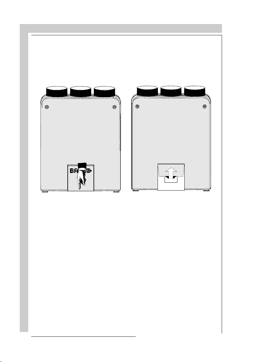
Battery installation in the RCU.
A new battery (not yet installed to save the battery life
time) is delivered inside the plastic bag with the power
cord. Before using the RCU, start first the battery
installation procedure.
Remove the battery cover on the backside of the
remote control by pushing the indicated handle a little
to the bottom of the RCU. Lift up the top side of the
cover at the same time (fig. 1).
Insert the new 9 V battery (E-block type, e.g. 6F22S or
equivalent) in the lower compartment and connect the
battery to the contact plate.
Insert the battery into the lower compartment and put
the cover back.
CONTROLLING
fig.1
Insert here,
behind the
plastic cover, the
'Insert card for
RCU'. You can
Contact
plate
cut out the
correct insert
card on one of
CONTROLLING
Battery
the last pages of
this manual.
fig.2
310a.DRW
5-25-2
R5975238 BARCOVISION 701 MULTIMEDIA 070497
Page 37
CONTROLLING
The BARCOVISION 701 MULTIMEDIA can be controlled with
a. the RCU
b. the hardwired RCU (cable not included)
c. the local keypad.
Controlling the projector with the RCU and the hardwired RCU is the same.
How to use the RCU
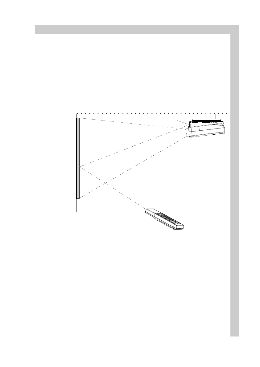
a) Point the front of the RCU towards the reflective screen surface
Ceiling
IR sensor
Screen
RCU700
b) Point the front of the RCU towards one of the IR sensors in the projector.
When using the wireless remote control, make sure you are within the effective
operating distance (30m, 100ft in a straight line). The remote control unit will not
function properly if strong light strikes the sensor window or if there are obstacles
between the remote control unit and the projector's IR sensor.
R5975238 BARCOVISION 701 MULTIMEDIA 070497
CONTROLLING
5-3
Page 38

CONTROLLING
Front of projector
45°
Rear side of projector
45°
ENTER
FREEZ
0
9
7
8
5
6
43
2
1
RCU
45°
45°
ENTER
FREEZ
0
9
7
8
6
5
43
21
c) RCU used in a hardwired configuration.
COMM PORT
RS232OUTRS 232 IN IR
REMOTE R G(S) BSVIDEO
(800 peripherals)
S-VIDEO
CONTROLLING
219
Plug one end of the remote cable in the connector on the bottom of the RCU and the
second side in the connector in the rear panel of the BARCOVISION 701 MULTIMEDIA labelled '
5-45-4
REMOTE
'.
R5975238 BARCOVISION 701 MULTIMEDIA 070497
Page 39

CONTROLLING
Projector address
a. hardware set up of the projector address.
Every projector requires an individual address between 0 and 16 which is set with
hardware DIP switches inside the projector. To change that address, contact a
BARCO authorized technician.
b. How to control the projector.
The projector's address may be set to any value between 0 and 16. When the address
is set, the projector can be controlled now with :
- the RCU for addresses between 0 and 9.
- computer, e.g. IBM PC (or compatible), Apple MAC, etc. for addresses between
0 and 16 (only when the optional RS232 communication port is installed)
Note : a projector will respond to an RCU set to an address of '0' regardless of what
address is set in the projector itself.
c. Using the RCU.
Before using the RCU, it is necessary to enter the projector address into the RCU
(only when that address is between 1 and 9). The projector with the corresponding
address will listen to that specific RCU.
When address 0, 'zero address' is programmed into the RCU, every projector, without
exception will listen to the commands given by this RCU.
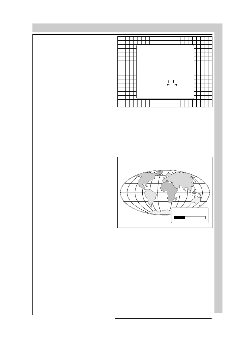
How to display a projector address?
Press the ADDRESS key (recessed key on the RCU) with a
pencil.
The projector's address will be displayed in a 'Text box'. This text box
disappears after a few seconds.
To continue using your RCU, it is
necessary to enter an address with
the digit buttons (address between
0 and 9). For example : if the
Address key displays projector
address 003, the press "3" digit
button on the RCU to set the RCU's
address to match the projector's
address. Do not press digit 003.
This will address the remote to '0'
and control all projectors in the
room.
R5975238 BARCOVISION 701 MULTIMEDIA 070497
PROJ EC TO R
ADDRESS
001
CONTROLLING
5-5
Page 40

CONTROLLING
How to program an address into the RCU?
Press the ADDRESS key (recessed key on the RCU) with a pencil and enter the
address with the digit buttons. That address can be any digit between 0 and 9.
When programming '0', zero address, the RCU will control a projector regardless of
the projector's address. This feature allows multiple projectors with different
addresses to be controlled by a single RCU.
Input selection
Source No Projector input Press digit button
1 Comp. Video 1
2 S-Video 2
3 RGBS or RGsB 3
4 RGB3S or RG3sB 4
5 (R-Y)Y(B-Y)S or
(R-Y)Ys(B-Y) 5
6 (R-Y)Y(B-Y)3S or
(R-Y)Y3s(B-Y) 6
Two possible ways of selecting an input :
a) With the digit buttons on the RCU, it is possible to select one of the four input
sources, Video, S-Video, RGsB or RGBS, RG3sB or RGB3S, (R-Y)Ys(B-Y) or
(R-Y)Y(B-Y)S, (R-Y)Y3s(B-Y) or (R-Y)Y(B-Y)3S.
b) With the local keypad :
press first the
General access
CONTROLLING
5-65-6
ADJUST
menu.
key to display the
ADJUST
STANDBY
R5975238 BARCOVISION 701 MULTIMEDIA 070497
EXIT
ENTER
Page 41

CONTROLLING
Use the control disk to highlight the
desired source number. Push the
control disk up or down to move the
cursor up and down, push the con-
trol disk to the left or to the right to
move the cursor to the left and to
the right.
ENTER
Press
lection.
When a valid and available source
is selected, there will be informa-
tion displayed on the screen about
that source. This information in-
cludes :
- Source number
- Horizontal frequency
- Vertical frequency
to confirm your se-
GENERAL ACCESS
5 6
3 4
1 2
Enter ADJUST
Select with ,
or
then <ENTER>.
<EXIT> to return
SHARPNESS
TINT
COLOR
BRIGHTNESS
CONTRAST
Source 2
Fh= 15.6 kHz
Fv= 50 Hz
When the entry is a non valid
source number, a warning appears
on the screen : '
able
'.
R5975238 BARCOVISION 701 MULTIMEDIA 070497
input not avail-
WARNING
input no t
availab le
CONTROLLING
5-7
Page 42

CONTROLLING
When a valid source number is
selected, the projector will display
this source or it will wait on the
selected source number until the
source becomes available. A message 'source not available' will be
displayed for a short time.
WARNING
source not
available
Picture controls
The picture controls can be adjusted with :
a) The RCU. The control keys are located on the left side of the key panel of the RCU
and indicated with the name of the control and an icon.
When an image control is pressed, a text box with bar scale and the function
name of the control, e.g. 'brightness...' appears on the screen (only if text is ON).
The length of the bar scale indicates the current memorized setting for this
source. The bar scale changes as the + or - buttons of the control are pressed.
b) The local keypad
All controls are hidden in the General access menu.
ADJUST
- Press
General access
to display the
menu.
- Use the control disk to highlight
the desired analog control and
ENTER
press
to select.
ADJUST
STANDBY
EXIT
ENTER
CONTROLLING
5-85-8
R5975238 BARCOVISION 701 MULTIMEDIA 070497
Page 43
CONTROLLING
GENERAL ACCESS
SHARPNESS
TINT
5 6
3 4
1 2
Enter ADJUST
Select wi th ,
or
then <ENTER>.
<EXIT> to return
When a picture control is selected, a text box with bar scale and the function name
of the control appear on the screen. The length of the bar scale indicates the current
memorized setting for this source (percentage scale). The bar scale changes as the
control disk is pushed to the left or to the right.
Brightness Control
COLOR
BRIGHTNESS
CONTRAST
A correct
'brightness'
setting is important for good image reproduction. Adjust the brightness with the
+ button and - button (RCU) or
pushing the control disk to the left
or to the right (local keypad) until
the darkest parts of the picture appear black.
A bar scale gives a visual indication on the screen of the current
brightness setting while pressing
on the above indicated buttons. If
the bar scale is not visible on the
screen, press '
TEXT
' once and re-
try the above indicated buttons.
The bar scale increases when
pressing on the + button (higher
brightness) and decreases when
pressing on the - button (lower
brightness).
R5975238 BARCOVISION 701 MULTIMEDIA 070497
BRIGHTNESS
35
189
CONTROLLING
5-9
Page 44

Contrast Control
A correct 'contrast' setting is important for good image reproduction.
Adjust the contrast to the level you
prefer, according to room lighting
conditions.
A bar scale gives a visual indication
on the screen of the current contrast setting while pressing the + or
- buttons (RCU) or pushing the control disk to the left or to the right
(local keypad). If the bar scale is
not visible on the screen, press
TEXT
'
' key once and retry the above
indicated buttons.
The bar scale increases when
pressing on the + button (higher
contrast) and decreases when
pressing on the - button (lower con-
trast).
Color Saturation Control
Color saturation is only active for
Video and S-Video. Adjust the
color intensity of the picture. Adjust the color saturation using the +
and - buttons (RCU) or pushing
the control disk to the left or to the
right (local keypad). A bar scale
gives a visual indication on the
screen of the current color setting
while pressing on the above indicated buttons. If the bar scale is
not visible on the screen, press
TEXT
'
' key once and retry the
above indicated buttons. The bar
scale increases when pressing on
the + button (richer colors) and
decreases when pressing the button (lighter colors).
CONTROLLING
CONTROLLING
CONTRAST
70
COLOR
70
5-105-10
R5975238 BARCOVISION 701 MULTIMEDIA 070497
Page 45

CONTROLLING
Tint Control
Tint is only active for Video and SVideo. Tint control is effective
only when using the NTSC 4.43 or
NTSC 3.58 system. A bar scale
gives a visual indication on the
screen of the current tint setting
while pressing the + or - buttons
(RCU) or pushing the control disk
to the left or to the right (local
keypad). If the bar scale is not
visible on the screen, press the
TEXT
'
' key once and retry the
above indicated buttons.
The bar scale increases when
pressing on the + button and decreases when pressing the - button.
Sharpness Control.
Sharpness control only active for
Video and S-Video. A bar scale
gives a visual indication on the
screen of the current sharpness
setting while pressing the + or buttons (RCU) or pushing the control disk to the left or to the right
(local keypad). If the bar scale is
not visible on the screen, press
TEXT
'
' key once and retry the
above indicated buttons.
The bar scale increases when
pressing on the + button (sharper
picture) and decreases when
pressing on the - button (softer
picture).
TINT
70
SHARPNESS
3 dB
The Pause key.
When the Pause key is pressed, the image projection is stopped but the projector
remains with full power for immediate restart.
To restart the image :
- Press the Pause key,
- Select a source number.
R5975238 BARCOVISION 701 MULTIMEDIA 070497
CONTROLLING
5-11
Page 46

CONTROLLING
CONTROLLING
5-125-12
R5975238 BARCOVISION 701 MULTIMEDIA 070497
Page 47

START UP OF THE ADJUSTMENT MODE
START UP OF THE ADJUSTMENT MODE
R5975238 BARCOVISION 701 MULTIMEDIA 070497
START UP OF THE ADJUSTMENT MODE
6-1
Page 48

START UP OF THE ADJUSTMENT MODE
Entering the adjustment mode
ADJUSTMENT MODE
Select a path from
below:
RANDOM ACCESS
Select wi th or
then <ENTER >
<EXIT> to return
GUIDED
INSTALLATION
SERVICE
IRIS
source 1
START UP OF THE ADJUSTMENT MODE
Installation
(only for qualified
technician)
6-2
Random Access
Adjustment
IRISIRIS
Service
Guided
Adjustment
R5975238 BARCOVISION 701 MULTIMEDIA 070497
Page 49

START UP OF THE ADJUSTMENT MODE
Adjustment mode
All picture geometry and convergence adjustments are made while in the
'Adjustment mode'. Two possible ways to enter the adjustment mode :
a) Using the RCU.
Press the
ADJUST
key.
The projector displays the path selection menu.
b) Using the local keypad.
Press the
ADJUST
The projector displays the
access menu
key.
General
.
Use the control disk to high-
enter ADJUST
light
. The path selection
ENTER
and press
menu will be displayed.
Enter ADJUST
ADJUST
STANDBY
GENER AL ACCE SS
5 6
3 4
1 2
Select with ,
or
then <ENTER>.
<EXIT> to return
SHARPNESS
TINT
COLOR
BRIGHTNESS
CONTRAST
EXIT
ENTER
R5975238 BARCOVISION 701 MULTIMEDIA 070497
START UP OF THE ADJUSTMENT MODE
6-3
Page 50

START UP OF THE ADJUSTMENT MODE
Note : to adjust the Analog picture control while in the 'Adjustment mode', press
the
ADJUST
Push the control disk up or
down to select the analog control to be adjusted and press
the
ENTER
When the analog control is
adjusted the projector returns
automatically to the General
access menu. When you want
to return to the Adjustment
mode, press
select
ENTER
mode.
key. The next General Access menu will be displayed.
GENERAL ACCESS
key to confirm.
Select with ,
or
EXIT
quit ADJUST
, otherwise
and press
then <ENTER>.
<EXIT> to return
to return to operational
SHARPNESS
TINT
COLOR
BRIGHTNESS
CONTRAST
quit ADJUST
643
START UP OF THE ADJUSTMENT MODE
You are now in the
selections and also vertical and horizontal adjustments. The
'Adjustment mode'
. The control disk is used to make menu
and
ENTER
EXIT
keys are used to move forward and backward through the menu structure. The
ADJUST
key can be used to terminate the adjustment mode while a path
selection menu (head menu) is displayed.
There are 5 possible paths to follow once in the Adjustment mode. They are :
INSTALLATION
- Installation
should be selected if the projector has been relocated and/
or a different screen size is
desired.
When selecting 'Installation',
the user or operator will be
warned to call a qualified technician to perform the installation procedure (see example
of projected warning on next
page).
GUIDED
- Guided should be selected if the user intends to perform a complete
ADJUSTMENT MODE
Select a path from
below:
GUIDED
RANDOM ACCESS
INSTALLATION
SERVICE
IRIS
source 1
Select w ith o r
then <ENTER>
<EXIT> to return
alignment of the projected image. All of the necessary geometry and convergence adjustments are made in a predetermined sequence.
RANDOM ACCESS
- Random Access should be selected if the user intends to
make only a few adjustments.
SERVICE
- Service should be selected if the user intends to delete blocks, change
password or apply information.
6-4
- This selection will only be available when the autoconvergence unit IRIS
IRIS
is connected to the projector.
R5975238 BARCOVISION 701 MULTIMEDIA 070497
Page 51

START UP OF THE ADJUSTMENT MODE
While in Guided or Random Access adjustment Mode, the user may use an
external source, an internally generated genlocked pattern or an internally
generated multifrequency cross hatch pattern as a setup pattern.
Warning during the start up of
the installation mode.
RISK OF ELECTRICAL SHOCK
NO USER ADJUSTABLE PARTS
Some items in the Adjustment mode are password protected. While selecting
such an item, the projector asks you to enter your password. (Password
protection is only available when the password DIP switch on the controller
module is in the ON position. Contact a BARCO authorized technician when no
password is requested during the adjustment procedure and password protection is desired.)
Your password contains 4 digits.
a) Adjusting the projector with
the RCU.
WARNING
INSIDE
THE FOLLOWING
INSTALLATION MENUS
ARE RESERVED TO,
AND TO BE PERFORMED ONLY
BY BARCO PERSON NEL, OR
BARCO AUTHORIZED DEALERS
IF QUALIFI ED, PRESS
<ENTER> TO CONTINUE, OR
IF NOT, <EXIT> T O RETURN.
Enter the digits with the numeric
keys on the RCU.
Example : 2 3 1 9
For each digit entered, a 'X' ap-
pears on the screen under the
displayed text 'enter password'.
When your password is correct,
you get access to the 'Adjustment mode'.
When the entered password is
wrong, The message
password !!!'
will be displayed.
'Wrong
The projector stays on the previous selected item.
Factory programmed
password :
R5975238 BARCOVISION 701 MULTIMEDIA 070497
0000
enter
passw ord
xxxx
WRONG
PASSWORD
!!!
197
198
START UP OF THE ADJUSTMENT MODE
6-5
Page 52

START UP OF THE ADJUSTMENT MODE
b) adjusting the projector with the local keypad.
When the 'compose password'
menu is displayed, select with control disk the first digit of your password and press
ENTER
. Continue
by selecting the second digit with
the control disk and press
ENTER
.
Handle in the same way for the
third and fourth digit.
When your password is correct,
you get access to the 'Adjustment
mode'.
When the entered password is
wrong, the message 'Wrong password' will be displayed.
Once the password is correctly entered, all other password protected items are
accessible without re-entering your password.
When re-entering the adjustment mode, it will be necessary to enter your
password again when selecting a password protected item.
COMPO SE
PASSWORD
???
7 8 9
4 5 6
1 2 3
0
Select with ,
or
then <ENTER>
<EXIT> to return
6-6
START UP OF THE ADJUSTMENT MODE
R5975238 BARCOVISION 701 MULTIMEDIA 070497
Page 53

GUIDED ADJUSTMENT MODE
GUIDED ADJUSTMENT MODEGUIDED ADJUSTMENT MODE
R5975238 BARCOVISION 701 MULTIMEDIA 070497
GUIDED ADJUSTMENT MODE
7-1
Page 54

GUIDED ADJUSTMENT MODE
Start up of the guided adjustment mode.
Push the control disk up or
down to highlight
GUIDED
on
the 'Adjustment mode' menu
and then press
ENTER
.
The Guided Adjustment mode
is password protected (when
the password function is active). Enter your password to
continue (see also chapter Start
up of the adjustment mode)
ADJUSTMENT MODE
Select a path from
below:
GUIDED
RANDOM ACCESS
INSTALLATION
SERVICE
IRIS
source 1
Select w ith o r
then <ENTER>
<EXIT> to return
continues to the password menu
ENTER
and then to Setup Pattern Selection
returns to operational mode.
EXIT
7-2
GUIDED ADJUSTMENT MODE
R5975238 BARCOVISION 701 MULTIMEDIA 070497
Page 55

GUIDED ADJUSTMENT MODE
Overview flowchart 'Guided Adjustment' procedure.
GUIDED ADJUSTMENT MODE
INSURE THAT
THE PROJECTOR HAS BEEN
INSTALLED CORRECTLY,
AND THAT T HE L ENSE S/CR TS
HAVE BEEN PROPER LY
FOCUSED AND ALIGNED.
ALL ADJU STMENT S ARE
MADE WITH THE ARROW KEYS
<ENTER> to con tinu e
<EXIT> t o re turn
Picture tuning
Horizontal & vertical
shift
Left - right corrections
Top - bottom corrections
Size - linearity adjustment
R5975238 BARCOVISION 701 MULTIMEDIA 070497
Convergence
Blanking
Color Balance
GUIDED ADJUSTMENT MODE
7-3
Page 56

Selecting Setup Pattern
If an external source is connected to the projector, the
Setup pattern menu will be displayed. Push the control disk
up or down to highlight the
desired setup pattern and then
press
Genlocked pattern : internally
generated cross hatch pattern,
locked on the external source.
Internal # pattern : internally
generated cross hatch pattern
and locked on internal generated sync signals. (No external
source necessary)
If no external source is connected to the projector, the internal cross hatch pattern menu
will be displayed.
ENTER
.
GUIDED ADJUSTMENT MODE
Choose
a setup pattern
from below:
SELECTED SOURCE
GENLOCKED PATTERN
INTERNAL # PATTERN
source 1
Select w ith o r
then <ENTER>
<EXIT> to return
continues to Guided Adjustment
ENTER
Mode or Internal # Pattern Selection
returns to Path Selection
EXIT
ADJUST
returns to operational mode
7-4
The menus in this manual are
created for an external source,
connected to one of the inputs,
and the 'Genlocked pattern' is
selected.
GUIDED ADJUSTMENT MODE
R5975238 BARCOVISION 701 MULTIMEDIA 070497
Page 57

GUIDED ADJUSTMENT MODE
Internal Cross Hatch Pattern
The Internal # pattern menu
will be displayed if the internal
cross hatch pattern has been
selected or if no source is connected to the projector.
The table below lists the factory preset frequencies available.
Push the control disk up or
down to highlight the desired
cross hatch frequency and then
ENTER
press
kHz/Hz
15.6/50 PAL/SECAM
15.7/60 NTSC
31.2/50 EDTV
31.5/60 IDTV
31.2/50 HDTV EUREKA
31.5/60 HDTV ATV
33.7/60 HDTV HI-VISION
15.8/60 EGA 1
21.8/60 EGA 2
31.5/70 VGA 1,2
35.5/87 VGA 4
.
INTERNAL # PATTERN
kHz / Hz
15.6/50 PAL/S ECAM
15.7/60 NTSC
31.2/50 EDTV
31.5/60 IDTV
31.2/50 HDTV EUREKA
31.5/60 HDTV ATV
33.7/60 HDTV HI-VISION
Select wi th or
<ENTER > to accept
<EXIT> to return
ENTER
continues to Guided Adjustment
Mode.
EXIT
returns to Setup Pattern Selection.
48.5/60 SUPER VGA 1
44.2/70 SUPER VGA 2
61.0/76 SUPER VGA 3
22.2/60 MAC CLASSIC
Note: Before continuing, insure that the lenses are properly focused and that the CRT
projection angle is correctly adjusted. If any misalignment is
noticed, consult a qualified
service technician.
R5975238 BARCOVISION 701 MULTIMEDIA 070497
GUIDED ADJUSTMENT MODE
INSURE THAT
THE PROJECTOR H AS BEE N
INSTALLED CORRECTLY,
AND THAT THE LENSES/CRTS
HAVE BEEN PROPERLY
FOCUSED AN D ALIGNED.
ALL ADJUSTMENTS ARE
MADE WITH THE ARROW KEYS
<ENTER> to continue
<EX IT> to retu rn
ENTER
continues with the Picture Tuning
EXIT
returns to Setup Pattern Selection or
Internal # Pattern Selection
ADJUST
returns to operational mode
GUIDED ADJUSTMENT MODE
7-5
Page 58

GUIDED ADJUSTMENT MODE
Picture tuning
Depending on the source type (video, S-Video, RGB(S) analog with composite
or Tri-level sync, component input with composite or Tri-level sync) the picture
tuning menu offers the possibility to toggle :
For Video, S-Video or Component video sources :
- The Synchronisation speed
- The Line Doubler feature (option)
For RGB analog or component input with composite or tri-level sync sources:
- Synchronisation speed
- Enhanced blue on or off
Sync Fast/Slow toggle
Highlight
control disk up or down and
press
ENTER
tween FAST and SLOW
Note : SYNC is normally used
in the SLOW position. The
FAST position is used to compensate for unsteady sync
pulses from older video playback equipment.
Hint : when the line doubler
feature is ON (active), toggle
the sync to FAST.
Line Doubler (option)
GUIDED ADJUSTMENT MODE
Line doubling is only possible for Video, S-Video or Component Video images
on standard line frequency.
To eliminate the video line patterns and to improve the image stability the line
doubler has to be switched on. The line doubler is default set in the ON position
when starting up for the first time. The setting of the line doubler will be saved
together with the source number.
Hint : when the line doubler feature is ON (active), toggle the sync to FAST.
When a bad video tape has to be displayed, switch off the line doubler feature to
obtain a stable image.
Sync
by pushing the
to toggle be-
PICTURE TUNING
SYNC : FAST
CHROMA DEL AY : PA L
CONTINUE
Select wi th or
<ENTER> to accept
<EXIT> to return
toggles between SLOW and FAST.
ENTER
returns to the Guided Adjustment menu.
EXIT
7-6
R5975238 BARCOVISION 701 MULTIMEDIA 070497
Page 59

GUIDED ADJUSTMENT MODE
Highlight
Line Doubler
ing the control disk up or down
and press
ENTER
between ON (active) and OFF
(non active)
Enhanced blue ON/OFF
Highlight
pushing the control disk up or
down and press
toggle between ON and OFF
(only available when RGB
analog signals are connected
to the projector).
When Enhanced Blue is ON,
the blue color will be displayed
as cyan.
Note : Enhanced blue is only
used when an RGBS or RGsB
analog signal from a computer
is being displayed. Enhanced
blue is not recommended for
non computer generated images.
For displaying graphics, this
Enhanced Blue function could
falsify the color reproduction.
In this case, put Enhanced
Blue OFF
Enhanced Blue
ENTER
by push-
to toggle
by
to
PICTURE TUNI NG
SYNC : FAST
CHROMA DE LAY : P AL
LINE DOUBLER : ON
CONTINUE
Select wi th or
<ENTER> to accept
<EXIT> to return
ENTER
toggles beween ON and OFF.
EXIT
returns to the Guided Adjustment Menu.
PICTURE TUNI NG
SYNC : FAST
ENHAN CED B LUE : ON
CONTINUE
Select wi th or
<ENTER> to accept
<EXIT> to return
ENTER
will toggle Enhanced Blue between
ON and OFF.
EXIT
will return to the Guided Adjustment
menu.
R5975238 BARCOVISION 701 MULTIMEDIA 070497
GUIDED ADJUSTMENT MODE
7-7
Page 60

GUIDED ADJUSTMENT MODE
Raster Centering on Green CRT Faceplate
The green raster must be
centered both horizontally and
vertically on the center of the
CRT surface. To center the
green raster, look into the green
lens and use the control to
move the raster.
Caution
It is necessary to look into the
lenses to perform these adjustments. To avoid eye discomfort while looking into the
lenses, reduce the contrast and
gradually increase the brightness level until the raster becomes visible.
continues to Green Raster Shift
ENTER
returns to Guided Adjustment Mode
EXIT
ADJUST
returns to operational mode
H AND V SHIFT
USE THE ARROW KEYS
TO CENTER THE RASTER
ON THE FACE PLATE OF THE
GREEN CRT HORIZONTALLY
AND VERTICALLY,
AND THEN TO SHIFT
THE RED A ND BL UE IMAGES
VERTICALLY, IN ORDE R
TO CONVER GE THE CENTE R
OF THE PROJECTED IMAGE.
<ENTER> to continue
<EX IT> to retu rn
7-8
GUIDED ADJUSTMENT MODE
Warning
: In order to ensure maximum CRT longevity and to avoid
CRT damage, do not shift the raster outside the phosphor area of the
CRT.
forbidden area
projected raster
crt facepl ate border
phosphor border
To begin the adjustment, press the
key.
ENTER
R5975238 BARCOVISION 701 MULTIMEDIA 070497
Page 61

GUIDED ADJUSTMENT MODE
correct ra ste r positi on
wrong ras ter p osition
After centering the green raster, press the
R5975238 BARCOVISION 701 MULTIMEDIA 070497
ENTER
key to continue.
ENTER
continues to Red Raster Shift
EXIT
returns to Horizontal and Vertical
Shift
GUIDED ADJUSTMENT MODE
7-9
Page 62

GUIDED ADJUSTMENT MODE
Shifting Red and Blue on Green
Use the control disk to shift the red image until the center coincides with the
center of the green image.
red or blue
image
green
image
When the red image is correctly positioned, press the
with the blue image.
Left-Right (East-West) Adjustments
Left-right adjustments affect
only the vertical lines of the
setup pattern. Only the green
image is displayed while making left-right adjustments. The
red and blue images will automatically be corrected in the
same manner.
Convergence corrections are
GUIDED ADJUSTMENT MODE
automatically disabled for the
duration of these adjustments.
Press the
ENTER
key to con-
tinue.
ENTER
continues to blue raster shift
ENTER
returns to green raster shift
EXIT
LEFT-RIGHT (E/W)
ADJUST
VERTICAL CENTER LINE
BOW AND SKEW,
SIDE BOW A ND KEYSTONE.
AFTER S QUARI NG
THE SIDES OF THE IMAGE,
ADJUST THE D ESIRED
SCREEN WIDTH. (H SIZE)
<ENTER> to continue
<EX IT> to retu rn
continues to vertical centerline bow
ENTER
adjustment
returns to Picture Tuning
EXIT
ADJUST
returns to operational mode
key to continue
7-10
R5975238 BARCOVISION 701 MULTIMEDIA 070497
Page 63

GUIDED ADJUSTMENT MODE
Vertical Centerline Bow Adjustment
The vertical centerline bow
adjustment corrects for curvature in the horizontal direction
in the middle of the picture for
the vertical lines.
Push the control disk to the
left or to the right to adjust the
vertical centerline bow of the
setup pattern and then press
ENTER
the
key to continue.
Vertical Centerline Skew Adjustment
Correct by pushing
the control disk to
the right
Vertical centerline
Correct by pushing
the control disk to
the left
The vertical centerline skew
function corrects for tilting of
the vertical lines in the middle
of the picture.
Push the control disk to the
right or to the left to adjust the
vertical centerline skew of the
setup pattern until this line is
straight. Misalignment of the
outer vertical lines will be corrected with the bow and keystone corrections. Press
TER
to continue.
R5975238 BARCOVISION 701 MULTIMEDIA 070497
EN-
Correct by pushing
the control disk to
the right
Vertical centerline
Correct by pushing
the control disk to
the left
GUIDED ADJUSTMENT MODE
7-11
Page 64

Right Keystone Adjustment
The right keystone function
corrects the keystone geometry distortion of the vertical
lines on the right side of the
image.
Push the control disk to the
right or to the left to adjust the
right keystone (vertical lines)
of the setup pattern and press
to continue
ENTER
Left Keystone Adjustment
The left keystone function corrects the keystone geometry
distortion of the vertical lines
on the left side of the image.
Push the control disk to the
right or to the left to adjust the
left keystone (vertical lines)
of the setup pattern and press
to continue
ENTER
GUIDED ADJUSTMENT MODE
Correct by pushing
the control disk to
the right.
Correct by pushing
the control disk to
the left.
Correct by pushing
the control disk to
the right.
Correct by pushing
the control disk to
the left.
Right Bow Adjustment
The right bow function corrects
for curvature occurring the ver-
GUIDED ADJUSTMENT MODE
7-12
tical lines at the right of the
displayed image.
Push the control disk to the
right or to the left to adjust the
right bow of the setup pattern
(vertical lines) and press
to continue.
TER
Correct by pushing
the control disk to
the right.
EN-
Correct by pushing
the control disk to
the left.
R5975238 BARCOVISION 701 MULTIMEDIA 070497
Page 65

GUIDED ADJUSTMENT MODE
Left Bow Adjustment
The left bow function corrects
for curvature occurring the vertical lines at the left of the displayed image.
Push the control disk to the
left or to the right to adjust the
left bow of the setup pattern
(vertical lines) and press
TER
to continue.
Horizontal Size Adjustment
Adjust the horizontal size by
pushing the control disk to the
left or to the right until the correct image width is obtained.
Note :
- if the internal # pattern was
selected, this pattern remains on the screen.
- if the genlocked pattern was
selected, the external source
will be displayed.
A bar scale and a number
indicator(between 0 and 100)
give a visual indication of the
horizonal size adjustment.
Correct by pushing
the control disk to
the right.
EN-
Correct by pushing
the control disk to
the left.
H SIZE
70
R5975238 BARCOVISION 701 MULTIMEDIA 070497
GUIDED ADJUSTME NT MODE
7-13
Page 66

GUIDED ADJUSTMENT MODE
H size too
large
Ideal image width
H size too
small
Top-Bottom (North-South) Adjustments
Correct by pushing
the control disk to
the left.
Correct by pushing
the control disk to
the right.
7-14
GUIDED ADJUSTMENT MODE
Top-Bottom
adjustments affect
only the horizontal lines of the
setup pattern. These adjustments are performed only on
the green image. The red and
blue images are automatically
corrected in the same manner.
Convergence corrections are
automatically disabled for the
duration of these adjustments.
Press the
ENTER
key to con-
tinue.
TOP-BO TTOM
ADJUST HORIZONTAL
CENTERLINE BOW AND SKEW,
TOP BOW AND KEYSTONE,
BOTTOM BOW AND KEYSTONE.
<ENTER> to conti nue
<EX IT> to retu rn
R5975238 BARCOVISION 701 MULTIMEDIA 070497
Page 67

GUIDED ADJUSTMENT MODE
Horizontal Centerline Skew Adjustment
The horizontal skew function
corrects for tilting of the horizontal lines in the middle of the
picture.
Push the control disk up or
down to adjust the horizontal
centerline skew of the setup
pattern.
A bar scale and a numeric
indicator (between 0 and 100)
will give a visual indication of
the skew correction.
Horizontal Centerline Bow Adjustment
Correct by pushing
the control disk up
Hor. centerline
Correct by pushing
the control disk
down.
The horizontal centerline bow
function corrects for curvature
of the horizonal lines in the
vertical direction in the middle
of the picture.
Push the control disk up or
down to adjust the horizontal
centerline bow of the setup
pattern.
A bar scale and a numeric indicator (between 0 and 100 ) will
give a visual indication of the
bow correction.
Top Keystone Adjustment
The top keystone function corrects for keystone geometry
distortion of the horizontal lines
in the upper part of the picture.
Adjust the horizontal lines in
the upper part of the picture
with the control disk until these
lines are straight. Press
TER
to continue.
A bar scale and a number indicator (between 0 and 100 ) will
give a visual indication of the
keystone correction.
R5975238 BARCOVISION 701 MULTIMEDIA 070497
EN-
Correct by pushing
the control disk
down.
Hor. c ent erline
Correct by pushing
the control disk up.
Correct by pushing
the control disk
down.
Correct by pushing
the control disk up.
GUIDED ADJUSTMENT MODE
7-15
Page 68

GUIDED ADJUSTMENT MODE
Top Bow Adjustment
The top bow function corrects
for curvature occurring in the
upper part of the image.
Adjust the bow of the horizontal lines in the upper side of the
image by pushing the control
disk up or down until these
lines are straight.
A bar scale and a number indicator below indicate the
amount of adjustment.
Bottom Keystone Adjustment
The bottom keystone function
corrects for keystone geometry
distortion of the horizontal lines
in the lower part of the image.
Adjust the horizontal lines in
the lower part of the image by
pushing the control disk up or
down until these lines are
straight.
A bar scale and a number indicator (between 0 and 100) will
give a visual indication of the
adjustment.
Correct by pushing
the control disk up.
Correct by pushing
the control disk
down.
Correct by pushing
the control disk up.
Correct by pushing
the control disk
down.
Bottom Bow Adjustment
The bottom bow function corrects for curvature occurring
GUIDED ADJUSTMENT MODE
7-16
in the lower part of the image.
Push the control disk up or
down to adjust the bottom bow
in the lower part of the setup
pattern. Adjust until the horizontal lines are straight.
A bar scale and a number
indicator (between 0 and 100
%) give a visual indication of
the adjustment.
Correct by pushing
the control disk up.
Correct by pushing
the control disk
down.
R5975238 BARCOVISION 701 MULTIMEDIA 070497
Page 69
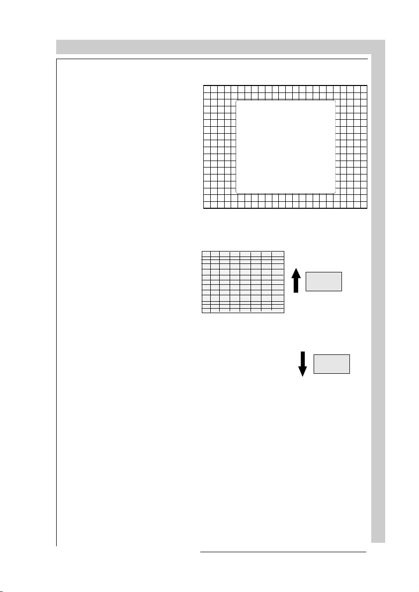
GUIDED ADJUSTMENT MODE
Size-linearity Adjustment
Size adjustments affect the
height and width of the projected image. The vertical linearity adjustment is used to
adjust the horizontal lines of
the setup pattern until the spacing between them is even. The
horizontal phase adjustment is
used to shift the image horizontally across the raster.
Vertical Linearity Adjustment
Adjust the vertical linearity with
the control disk until the distance between the horizontal
lines of the set up pattern are
equal.
SIZE-LINEARITY
ADJUST VERTICAL SIZE
AND LINEA RITY, IN OR DER
TO ADJUST THE DESIRED
IMAGE DIMENSIONS.
USE THE H PHASE CONTROL
TO SHIFT THE IMAGE
WITH RESPECT TO
THE RASTER.
<ENTER> to conti nue
<EX IT> to retu rn
Correct by pushing
the control disk up.
Correct by pushing
the control disk
down
R5975238 BARCOVISION 701 MULTIMEDIA 070497
GUIDED ADJUSTMENT MODE
7-17
Page 70

Vertical Size Adjustment
Adjust the vertical size by pushing the control disk up or down
until the exact image height is
obtained.
Note :
- if the internal # pattern was
selected, this pattern remains on the screen.
- if the genlocked pattern was
selected, the external
source will be displayed.
Hint :
In order to avoid loss of resolution in the projected image and
to ensure maximum CRT longevity, do not use an
exessively small vertical size
setting.
A bar scale and a number indicator (between 0 and 100 )
give a visual indication of the
vertical size adjustment.
GUIDED ADJUSTMENT MODE
V SIZE
70
7-18
Correct by pushing
the control disk
down.
GUIDED ADJUSTMENT MODE
Correct by pushing
the control disk up.
R5975238 BARCOVISION 701 MULTIMEDIA 070497
Page 71
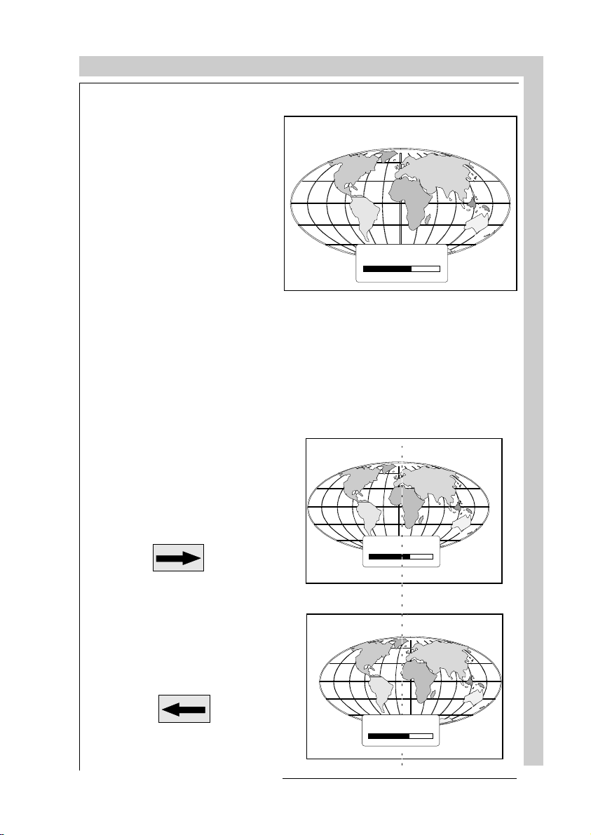
GUIDED ADJUSTMENT MODE
Horizontal Phase Adjustment
Note : No horizontal phase
adjustment is available on the
internal # pattern.
For external sources :
If the raster shift is correctly
adjusted, the text box H phase
is projected in the middle of
the raster. At that moment,
the >< indicates the middle of
the raster.
Adjust the hor phase control
until the middle of the projected image is equal with the
middle of >< .
Note :
- if the genlocked pattern was
selected, the external
source will be displayed.
A bar scale and a number indicator (between 0 and 100)
on the screen give a visual
indication of the horizontal
phase adjustment.
><
H PHASE
70
Correct by pushing
the control disk to
the right.
Correct by pushing
the control disk to
the left.
R5975238 BARCOVISION 701 MULTIMEDIA 070497
><
H PHASE
70
><
H PHASE
70
GUIDED ADJUSTMENT MODE
7-19
Page 72

Convergence Adjustment
Convergence adjustments affect both the horizontal and
vertical lines of the setup pattern. These adjustments are
performed on the red image
while superimposed on the
green image and then on the
blue image while superimposed on the green image.
The screen area is divided into
25 areas. Within each area it is
possible to move the horizontal and vertical lines of the red
and blue picture until they coincide with the green lines.
GUIDED ADJUSTMENT MODE
CONVERGENCE
START WITH GREEN ONLY,
THEN RED ON GREEN,
THEN B LUE O N GR EEN.
USE THE ARROW KEYS FOR
HORIZONTAL A ND VERTI CAL
ADJUSTMENTS IN THE AREA
INDICATED BY THE BOX.
<ENTER> WI LL MOVE
THE BOX TO THE NEXT AR EA
TO BE CONVERGE D, AND
<EXIT> WILL MOVE IT BACK
TO THE PREVIOUS.
<ENTER> to conti nue
<EX IT> to retu rn
25
23
9
15
17
GUIDED ADJUSTMENT MODE
Use the control disk to make
24
22
8
14
16
horizontal and vertical convergence adjustments in the area
indicated by the box. Pressing
12345
ENTER will move the box to
the next area of the setup pattern to be converged. Pressing EXIT will move the box back
to the last area.
1820
21 19 11 13
6
10
12
7
The ‘guided adjustment’ program will start with the convergence adjustment of
the red picture on the green and continues with the blue image on the green
image.
Attention : when green convergence adjustments are available (option). The
control software starts with these green corrections (the menu will indicate it also).
Adjust until the vertical and horizontal lines are straight.
green i mage
red image
CONVERGE
ADJUSTMENT
70
397
7-20
R5975238 BARCOVISION 701 MULTIMEDIA 070497
Page 73

GUIDED ADJUSTMENT MODE
Blanking Adjustment
Blanking adjustments affect
only the edges of the projected
image and are used to frame
the projected image on to the
screen and to hide or black out
unwanted information (or
noise). A 0% on the bar scale
indicates no blanking.
BLANKING
ADJUST THE TOP , BOTTOM,
LEFT AND RIGHT BLAN KING
IN ORDER TO FRAME
THE PROJECTED IMAGE
ONTO THE SCRE EN.
The following blanking corrections are possible :
- top blanking
- bottom blanking
- left blanking
- right blanking
Note :
- if the internal # pattern was
selected, this pattern remains on the screen.
- if the genlocked pattern was
selected, the external source
will be displayed.
Left blanking
<ENTER> to conti nue
<EX IT> to retu rn
Top blanking
Bottom blanki ng
Right blanking
R5975238 BARCOVISION 701 MULTIMEDIA 070497
GUIDED ADJUSTMENT MODE
7-21
Page 74

Top blanking adjustment
GUIDED ADJUSTMENT MODE
Push the control disk up or
down to adjust the top blanking of the setup pattern. Press
to continue.
ENTER
Bottom blanking adjustment
Push the control disk up or
down to adjust the bottom
blanking of the setup pattern.
unwanted in formation
(to be blanked out)
Correct by pushing
the control disk
down.
useful information
(to be displayed)
Correct by pushing
the control disk up
Correct by pushing
the control disk
down.
useful information
(to be displayed)
Correct by pushing
the control disk up.
7-22
unwanted infor mation
(to be blanked out)
GUIDED ADJUSTMENT MODE
R5975238 BARCOVISION 701 MULTIMEDIA 070497
Page 75

GUIDED ADJUSTMENT MODE
Left blanking adjustment
Push the control disk to the
right or to the left to adjust the
left blanking of the setup pattern.
ENTER
continues to right
blanking adjustment.
EXIT
returns to bottom blank-
ing adjustments.
Right blanking adjustment
Push the control disk to the
right or to the lef to adjust the
right blanking of the setup pattern.
unwanted information
(to be blanked out)
useful information
(to be displayed)
unwanted information
(to be blanked out)
Correct by pushing
the control disk to
the right.
Correct by pushing
the control disk to
the left.
Correct by pushing
the control disk to
the left.
Correct by pushing
the control disk to
the right.
R5975238 BARCOVISION 701 MULTIMEDIA 070497
useful information
(to be displayed)
GUIDED ADJUSTMENT MODE
7-23
Page 76

GUIDED ADJUSTMENT MODE
Color Balance
Use the control disk to select
between :
- Fixed Color Balance (one of
the 4 predefined values)
- Custom white balance
- Custom black balance
Fixed Color Balance
4 color temperatures are prepro-
grammed :
- 3200 K (reddish)
COLOR BALANCE
FIXED COLOR B ALANCE
3200 4 900 6500 93 00
CUSTOM WHITE BALANCE
CUSTOM BLACK BALANCE
CONTINUE
select with arrow keys
then <ENTER>.
You can adjust red wi th
or an d blue w ith or
<EXIT> to return
- 4900 K
- 6500 K (white)
- 9300 K (bluish)
Select one of the 4 preprogrammed color temperatures with the control disk and
press
Press
to display the desired color balance on the screen.
ENTER
again to continue.
ENTER
Custom White Balance
892
7-24
GUIDED ADJUSTMENT MODE
Select custom white balance with the control disk and press
ENTER
to start the
adjustment. Push the control disk up or down to adjust red gain and push the
control disk to the right or to the left to adjust the blue gain. A bar scale indicates
the amount of adjustment.
Custom Black Balance
Select custom black balance with the control disk and press
adjustment. Push the control disk up or down to adjust the red cut off and push
the control disk to the right or to the left to adjust the blue cut off.
When the color balance is adjusted, select continue with the control disk and
press
ENTER
.
R5975238 BARCOVISION 701 MULTIMEDIA 070497
ENTER
to start the
Page 77

RANDOM ACCESS ADJUSTMENT MODE
RANDOM ACCESS ADJUSTMENT MODE
Starting up the random access adjustment mode
Overview flow chart 'Random Access adjustment mode'
Selecting Setup Pattern
Internal cross hatch pattern
Picture tuning
Color balance
Sync Fast/Slow
Line Doubler
Enhanced Blue
Geometry adjustments
Horizontal phase
Raster shift adjustment
Left-right adjustments
Top-Bottom adjustments
Horizontal size
Vertical linearity
Vertical size
Blanking adjustments
Convergence adjustments
Color select
R5975238 BARCOVISION 701 MULTIMEDIA 070497
RANDOM ACCESS ADJUSTMENT MODE
Page 78

RANDOM ACCESS ADJUSTMENT MODE
Starting up the random access adjustment mode.
Push the control disk up or
down to highlight
ACCESS"
TER
and then press
.
"RANDOM
EN-
Some items in the Random
access mode are password
protected (when the password
function is enabled). Enter your
password to continue. All other
password protected items are
now also available if you stay
in the adjustment mode.
ADJUSTMENT MODE
Select a path from
below:
GUIDED
RANDOM ACCESS
INSTALLATION
SERVICE
IRIS
Select w ith o r
then <ENTER>
<EXIT> to return
continues to Setup Pattern Selec-
ENTER
tion
returns to operational mode
EXIT
source 1
8-2
RANDOM ACCESS ADJUSTMENT MODE
R5975238 BARCOVISION 701 MULTIMEDIA 070497
Page 79

RANDOM ACCESS ADJUSTMENT MODE
Overview flowchart 'Random Access Adjustment' mode
RANDOM ACCE SS
ADJUSTMENT MODE
PICTURE TUNING
GEOMETRY
CONVERGENCE
COLOR SELECT
Sel ec t wi th or
<ENTER> to accept
<EXIT> to return
PICTURE TU NING
COLOR BAL AN CE
SYNC : FAST
LINE DOUBLER : ON
Select with or
<ENTER> to accept
<EX IT > to re tu r n
CONVERGENCE
GREEN ON LY
RED ON GRE EN
BLUE ON GRE EN
Select with or
then <ENT E R>
<EXIT> to retu rn
COLOR SELECT
RED
GREEN
BLUE
RED AND GREEN
BLUE AND GREEN
RED AND BL UE
Select with or
<ENTER> to accept
<EXIT> to return
GEOMETRY
H PHASE
RASTER SHIFT
LEFT - RIGHT (E-W)
TOP - BOTTOM (N-S)
H SIZE
V LINEARITY
V SIZE
BLANKING
Select with or
then <E NTE R>
<EXIT> to re turn
R5975238 BARCOVISION 701 MULTIMEDIA 070497
RANDOM ACCESS ADJUSTMENT MODE
Page 80
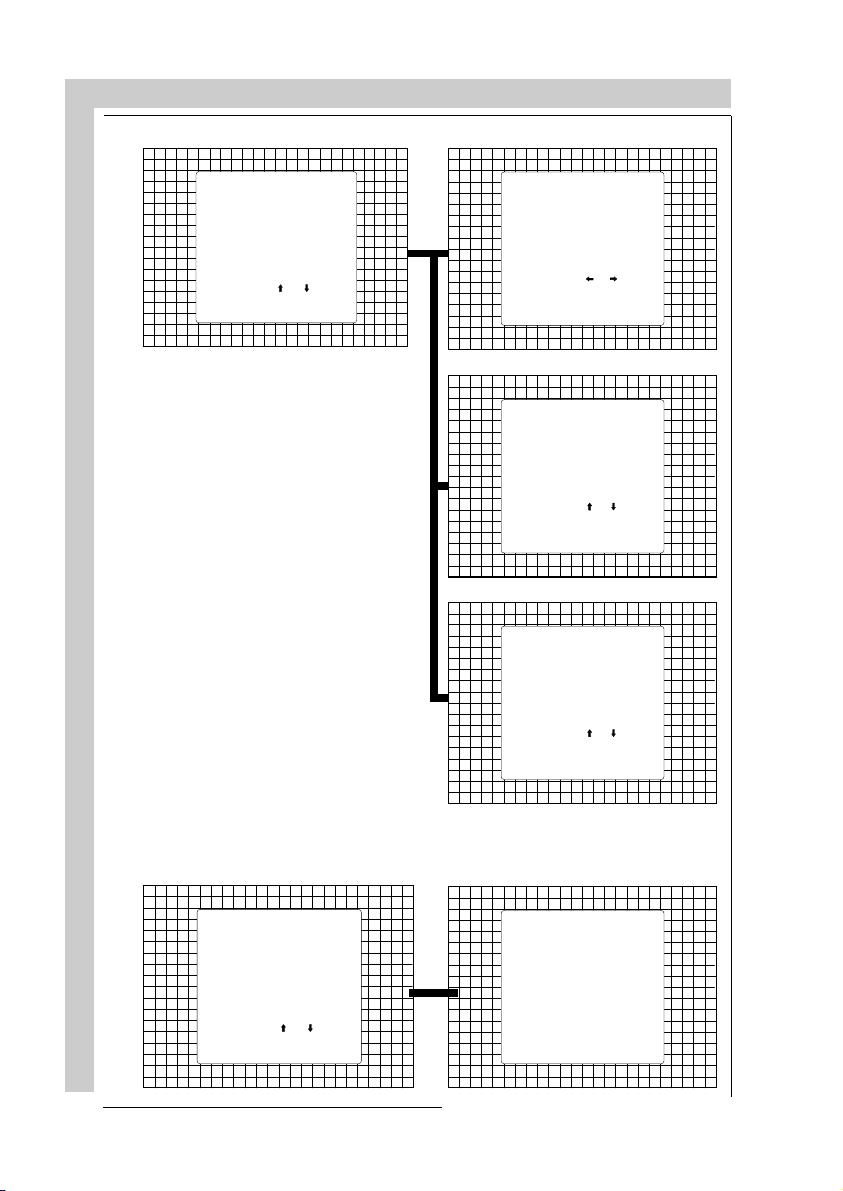
RANDOM ACCESS ADJUSTMENT MODE
GEOMETRY
H PHASE
RASTER SHIFT
LEFT - RIGHT (E-W)
TOP - BOTTOM (N-S)
H SIZE
V LINEARITY
V SIZE
BLANKING
Selec t with o r
then <ENTER>
<EXIT> to return
LEFT- RIGH T
V CENTERLINE BOW
V CENTERLINE SKEW
RIGHT BOW
RIGHT KEYSTONE
LEFT BOW
LEFT KEYSTONE
Select with o r
then <ENTER>
<EXIT> to return
TOP - BOTT OM
H CENTERLINE BOW
H CENTERLINE SKEW
TOP BOW
TOP KEYSTONE
BOTTOM BOW
BOTTOM KEYSTONE
Select with o r
then <ENTER>
<EXIT> to return
BLANKING
TOP
BOTTOM
LEFT
RIGHT
Select with o r
then <ENTER>
RANDOM ACCESS ADJUSTMENT MODE
<EXIT> to return
8-4
CONVERGENCE
GREEN ON LY
RED ON GREEN
BLUE ON GREEN
Select with or
then <ENT E R>
<EXIT> to retu rn
CONVER GENCE
SEL : select area
using
arrow keys
ADJ : adjust area
using
arrow keys
Toggle between
SEL and ADJ
with <ENTER>
<ENTER> continue
<EXIT> to return
R5975238 BARCOVISION 701 MULTIMEDIA 070497
Page 81

RANDOM ACCESS ADJUSTMENT MODE
Selecting Setup Pattern
If an external source is connected to the projector, the
path selection menu will be
displayed. Push the control
disk up or down to highlight
the desired setup pattern and
then press
Genlocked pattern : internally
generated cross hatch pattern,
locked on the external source.
Internal # pattern : internally
generated cross hatch pattern
and locked on internal generated sync signals. (No external source necessary)
If no external source is connected to the projector, the internal cross hatch pattern menu
will be displayed.
ENTER
.
continues to Random Access Ad-
ENTER
justment Mode or Internal # Pattern Selection
returns to Path Selection
EXIT
ADJUST
returns to operational mode
Choose
a setup pattern
from below:
SELECTED SOURCE
GENLOCKED PATTERN
INTERNAL # PATTERN
Select w ith o r
then <ENTER>
<EXIT> to return
source 1
The menus in this manual are
created for an external source,
connected to one of the inputs,
and the 'Genlocked pattern' is
selected.
R5975238 BARCOVISION 701 MULTIMEDIA 070497
RANDOM ACCESS ADJUSTMENT MODE
Page 82

RANDOM ACCESS ADJUSTMENT MODE
Internal Cross Hatch Pattern
The Internal # pattern menu
will be displayed if the internal
cross hatch pattern has been
selected or if no source is connected to the projector.
The table below lists the factory preset frequencies available.
Push the control disk up or
down to highlight the desired
INTERNAL # PATTERN
kHz / Hz
15.6/50 PAL/S ECAM
15.7/60 NTSC
31.2/50 EDTV
31.5/60 IDTV
31.2/50 HDTV EUREKA
31.5/60 HDTV ATV
33.7/60 HDTV HI-VISION
Select wi th or
<ENTER > to accept
<EXIT> to return
cross hatch frequency and then
press
kHz/Hz
ENTER
.
continues to the Random Access
ENTER
Adjustment Mode.
15.6/50 PAL/SECAM
15.7/60 NTSC
returns to the Setup Pattern Selection
EXIT
menu.
31.2/50 EDTV
31.5/60 IDTV
31.2/50 HDTV EUREKA
31.5/60 HDTV ATV
33.7/60 HDTV HI-VISION
15.8/60 EGA 1
21.8/60 EGA 2
35.8/87 VGA 4
48.5/60 SUPER VGA 1
44.2/70 SUPER VGA 2
61.0/76 SUPER VGA 3
22.2/60 MAC CLASSIC
31.5/70 VGA 1,2
Random access adjustment mode selection menu.
8-6
This is the main menu for the
RANDOM ACCESS ADJUSTMENT MODE
Random Access adjustment
mode.
Through this menu, the follow-
RANDOM ACCESS
ADJUSTMENT MODE
ing adjustments and features
are accessible :
- Picture tuning
enhanced blue (only for
PICTURE TUNING
GEOMET RY
CONVERGENCE
COLOR SELECT
RGB)
sync slow/fast(video/svideo)
Select wi th or
<ENTER> to accept
<EXIT> to return
color balance
- Geometry
- Convergence
- Color select
R5975238 BARCOVISION 701 MULTIMEDIA 070497
Page 83

RANDOM ACCESS ADJUSTMENT MODE
Picture tuning
Highlight
Picture tuning
pushing the control disk up or
down and press
The Picture tuning menu will
be displayed.
Depending on the input
source, the Picture tuning
menu will display different
items.
- Color balance
- Sync slow / fast
- Line doubling
- Enhanced blue ON/OFF
Color Balance
The Color Balance function is
used to select or adjust the
color temperature of white used
by the projector. The Color
Balance can be adjusted on
two different ways :
- fixed color balance. You
have the choice between 3200
K (reddish), 4900 K, 6500 K
(white) or 9300 K (bluish).
ENTER
.
by
PICTURE TUNING
COLOR BALANCE
SYNC : FAST
LINE DOUBLER : ON
Select wi th or
<ENTER> to accept
<EXIT> to return
PICTURE TUNING
COLOR BALANCE
SYNC : FAST
LINE DOUBLER : ON
Select wi th or
<ENTER> to accept
<EXIT> to return
Fixed Color Balance.
Highlight
one of the 4 prepro-
grammed color temperatures
with the control disk and press
to display the Color
ENTER
Balance.
R5975238 BARCOVISION 701 MULTIMEDIA 070497
COLOR BALANCE
FIXED COLOR B ALANCE
3200 4 900 6500 93 00
CUSTOM WHITE BALANCE
CUSTOM BLACK BALANCE
CONTINUE
select with arrow keys
then <ENTER>.
You can adjust red wi th
or an d blue w ith or
<EXIT> to return
892
RANDOM ACCESS ADJUSTMENT MODE
Page 84

Custom Color Balance.
Select custom white balance by pushing the control disk up or down and press
to start the adjustment.
ENTER
Push the control disk up or
down to adjust the red gain and
push the control disk to the left
or to the right to adjust the blue
gain. A bar scale indicates the
amount of adjustment.
Select custom black balance
with the control disk and press
to start the adjustment.
ENTER
Push the control disk up or
down to adjust the red cut-off
and push the control disk to the
left or to the right to adjust the
blue cut-off.
When the color balance is adjusted, select continue by pushing the control disk up or down
and press
ENTER
Sync Fast/Slow Adjustment
The sync function is used to
minimize horizontal jittering or
tearing at the top to the displayed image.
Highlight
trol disk and press
toggle between
RANDOM ACCESS ADJUSTMENT MODE
SLOW
Note: SYNC is normally used
in the SLOW position. The
FAST position is used to compensate for unsteady sync
pulses from older video playback equipment.
Hint : when the line doubler
feature is ON (active), toggle
the sync to FAST.
SYNC
.
RANDOM ACCESS ADJUSTMENT MODE
PICTURE TUNING
with the con-
FAST
ENTER
and
to
ENTER
and SLOW
EXIT
Adjustment menu.
COLOR BALANCE
SYNC : FAST
DECODING : EBU
LINE DOUBLER : ON
Select wi th or
<ENTER> to accept
<EXIT> to return
will toggle Sync between FAST
will return to the Randam Access
RED GAIN
70
8-8
R5975238 BARCOVISION 701 MULTIMEDIA 070497
Page 85

RANDOM ACCESS ADJUSTMENT MODE
Line Doubler
Line doubling is only possible for Video, S-Video or Component Video images on
standard line frequency.
To eliminate the video line patterns and to improve the image stability, the line
doubler has to be switched on. The line doubler is default set in the ON position
when starting up for the first time. The setting of the line doubler will be saved
together with the source number. Each time this source number is selected, the
last saved version will be loaded.
Highlight
control disk and press
to toggle between
and
Line Doubler
ON (active)
OFF (non active)
with the
ENTER
.
PICTURE TUNING
COLOR BALANCE
SYNC : FAST
DECODING : IRE
LINE DOUBLER : ON
Select wi th or
<ENTER> to accept
<EXIT> to return
will toggle Sync between FAST and
ENTER
SLOW
will return to the Randam Access Ad-
EXIT
justment menu.
Enhanced Blue On/Off Adjustment
Highlight
pushing the control disk up or
down and press
gle between ON and
available when RGB signals
are connected)
When 'Enhanced Blue' is ON,
the blue color will be displayed
as cyan.
ENHANCED BLUE
to tog-
ENTER
OFF
.(only
by
PICTURE TUNING
WHITE BALANCE
SYNC : FAST
ENHAN CED B LUE : ON
Note: Enhanced blue is only
used when an RGBS or RGsB
analog signal from a computer
is being displayed. Enhanced
blue is not recommended for
non computer generated images.
For displaying graphics, this
'Enhanced Blue' function could
falsify the color reproduction.
In this case, put Enhanced Blue
OFF.
R5975238 BARCOVISION 701 MULTIMEDIA 070497
Select wi th or
<ENTER> to accept
<EXIT> to return
will toggle Enhanced Blue be-
ENTER
tween ON and OFF
will return to the Random access
EXIT
main menu.
ADJUST
returns to operational mode
RANDOM ACCESS ADJUSTMENT MODE
Page 86

Color Select
RANDOM ACCESS ADJUSTMENT MODE
Highlight
pushing the control disk up
and down and press
display the color select menu.
COLOR SELECT
ENTER
by
to
RANDOM ACCESS
ADJUSTMENT MODE
PICTURE TUNING
GEOMET RY
CONVERGENCE
COLOR SELECT
Select wi th or
<ENTER> to accept
<EXIT> to return
continues to the color select menu
ENTER
will return to Internal Crosshatch
EXIT
Selection or Setup Pattern Selection Menu
ADJUST
returns to operational mode
Use the control disk to highlight a color (CRT) or combination of colors to display the
COLOR SE LECT
projected image in that specific color.
To select a new color, press
, the color selection
ENTER
menu appears again on the
RED
GREE N
BLUE
RED AND GREEN
BLUE AND GREE N
RED AND BL UE
screen. To terminate the color
select procedure, press
RANDOM ACCESS ADJUSTMENT MODE
EXIT
.
Select wi th or
<ENTER> to accept
<EXIT> to return
8-10
continues with the selected color or
ENTER
color combination.
returns to the Random access main
EXIT
menu.
R5975238 BARCOVISION 701 MULTIMEDIA 070497
Page 87

RANDOM ACCESS ADJUSTMENT MODE
Geometry Adjustments
The geometry adjustments have to be done only on the green image. These
adjustments are automatically implemented for the other color images : Left-right
(EW) and Top-Bottom corrections, blanking, Horizontal amplitude, vertical
amplitude, vertical linearity and Horizontal phase.
Highlight
GEOMETRY
by
pushing the control disk up or
down and press
ENTER
to dis-
play the geometry menu.
Within the geometry adjust
menu, the following adjustments are available :
- horizontal phase (not for internal # pattern).
- raster shift
- left-right corrections
- top-bottom corrections
- horizontal size
- vertical linearity
- vertical size
- blanking
RANDOM ACCESS
ADJUSTMENT MODE
PICTURE TUNING
GEOMET RY
CONVERGENCE
COLOR SELECT
Select wi th or
<ENTER> to accept
<EXIT> to return
ENTER
EXIT
will display Geometry menu
will return to Internal Crosshatch Se-
lection or Setup Pattern Selection Menu
ADJUST
returns to operational mode
GEOMETRY
H PHASE
RASTER SHIFT
LEFT - RIGHT (E-W)
TOP - BOTTOM (N-S)
H SIZE
V LINEARITY
V SIZE
BLANKING
Select w ith o r
then <ENTER>
<EXIT> to return
The convergence corrections
are disabled during geometry
corrections. The blanking corrections are only enabled during the blanking adjustments.
R5975238 BARCOVISION 701 MULTIMEDIA 070497
will display the selected option
ENTER
will return to Random Access Adjust-
EXIT
ment Mode main menu
ADJUST
returns to operational mode
RANDOM ACCESS ADJUSTMENT MODE
Page 88

RANDOM ACCESS ADJUSTMENT MODE
Horizontal Phase Adjustment
Push the control disk up or
down to highlight
Geometry menu
.
ENTER
H PHASE
on
and then press
GEOMETRY
H PHASE
RASTER SHIFT
LEFT - RIGHT (E-W)
TOP - BOTTOM (N-S)
H SIZE
V LINEARITY
V SIZE
BLANKING
Select w ith o r
then <ENTER>
<EXIT> to return
will select the horizontal phase
ENTER
adjustment.
returns to the Random access ad-
EXIT
justment main menu.
ADJUST
returns to operational mode.
Note : No horizontal phase
adjustment is available on the
internal # pattern.
For external sources :
If the raster shift is correctly
adjusted, the text box H phase
is projected in the middle of
the raster. At that moment,
RANDOM ACCESS ADJUSTMENT MODE
the >< indicates the middle of
the raster.
Adjust the hor phase control
until the middle of the pro-
><
H PHASE
70
jected image is equal with the
middle of >< .
continues to geometry menu .
ENTER
8-12
R5975238 BARCOVISION 701 MULTIMEDIA 070497
Page 89

RANDOM ACCESS ADJUSTMENT MODE
Note :
- if the genlocked pattern was
selected, the external
source will be displayed.
A bar scale and a number indicator (between 0 and 100) on
the screen give a visual indication of the horizontal phase adjustment.
Correct by pushing the
control disk to the right.
Correct by pushing the
control disk to the left.
><
H PHASE
70
><
H PHASE
70
R5975238 BARCOVISION 701 MULTIMEDIA 070497
RANDOM ACCESS ADJUSTMENT MODE
Page 90

Raster Shift Adjustment
The green raster must be
centered both horizontally and
vertically on the center of the
CRT surface. To center the
green raster, look into the green
lens and use the control disk
to move the raster.
CAUTION
It is necessary to look
into the lenses to
perform these adjustments. To avoid eye
discomfort while
looking into the lenses,
reduce the contrast
and gradually increase
the brightness level
until the raster becomes visible on the
face of the CRT.
RANDOM ACCESS ADJUSTMENT MODE
GEOMETRY
H PHASE
RASTER SHIFT
LEFT - RIGHT (E-W)
TOP - BOTTOM (N-S)
H SIZE
V LINEARITY
V SIZE
BLANKING
Select w ith o r
then <ENTER>
COARSE SHIFT
<EXIT> to return
GREEN HORIZONTAL
GREEN VERTICAL
RED VERTICAL
BLUE VERTICAL
Select wi th or
<ENTER> to accept
<EXIT> to return
RANDOM ACCESS ADJUSTMENT MODE
8-14
Warning
: In order to ensure maximum CRT longevity and to avoid CRT
damage, do not shift the raster outside the phosphor area of the CRT.
forbidden area
projected raster
crt faceplate border
phosphor border
To start the adjustment, use the arrow keys to highlight Raster shift and press
to display the coarse shift menu. Select 'Green horizontal' and adjust for
ENTER
correct raster position in horizontal direction on the phosphor.
Continue with 'Green vertical', then with 'Red vertical' and with 'Bleu vertical' until
the rasters of the 3 tubes correctly centered on the phosphor.
R5975238 BARCOVISION 701 MULTIMEDIA 070497
Page 91
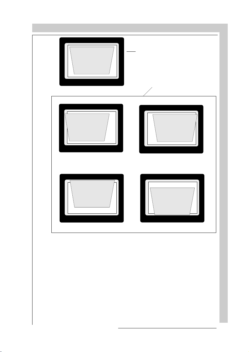
RANDOM ACCESS ADJUSTMENT MODE
correct raster position
wrong raster positi on
Press
to return to the Geometry menu.
EXIT
Note : Horizontal and Vertical shifts for Red and Blue should be end up with a
setting close to 50%. If these settings are significantly greater or lesser than 50%,
then contact a BARCO authorized service technician.
R5975238 BARCOVISION 701 MULTIMEDIA 070497
RANDOM ACCESS ADJUSTMENT MODE
Page 92

RANDOM ACCESS ADJUSTMENT MODE
Left-Right (east-west) Adjustments
Left-right and center adjustments affect only the vertical lines of the projected
image.
To start up the left-right and center adjustments, follow the next procedure :
Push the control disk up or
down to highlight
(E/W)
on the geometry menu
and then press
LEFT-RIGHT
.
ENTER
LEFT-RIGHT
V CENTERLINE BOW
V CENTERLINE SKEW
RIGHT BOW
RIGHT KEYSTONE
LEFT BOW
LEFT KEYSTONE
Select w ith or
then <E NTER>
<EXIT> to return
GEOMETRY
H PHASE
RASTER SHIFT
LEFT - RIGHT (E-W)
TOP - BOTTOM (N-S)
H SIZE
V LINEARITY
V SIZE
BLANKING
Select w ith o r
then <ENTER>
<EXIT> to return
will select Left-
ENTER
Right adjustment menu
returns to random ac-
EXIT
cess adjustment mode
main menu.
ADJUST
returns to opera-
tional mode
Only the green image is displayed while making left-right adjustments. The red
and blue images will automatically be corrected in the same manner. Convergence corrections are automatically disabled for the duration of these adjustments.
RANDOM ACCESS ADJUSTMENT MODE
The following adjustments can be executed
- vertical centerline bow
- vertical centerline skew
- side keystone (left - right)
- side bow (left - right)
8-16
All adjustment are indicated on
the screen with the function
name, a bar scale and a number
between 0 and 100. See next
example "V Certerline Bow"
V CENTERLINE
BOW
70
R5975238 BARCOVISION 701 MULTIMEDIA 070497
Page 93

RANDOM ACCESS ADJUSTMENT MODE
Adjust the next alignments until the
vertical lines are straight.
To enter an alignment, push the
control disk up or
down to highlight a
function and press
to activate
ENTER
this function.
Press
EXIT
LEFT-RIGHT
V CENTERLINE BOW
V CENTERLINE SKEW
RIGHT BOW
RIGHT KEYSTONE
LEFT BOW
LEFT KEYSTONE
Select with or
then <ENTER>
<EXIT> to return
to return.
Corrects for curvature of the vertical lines in the middle
of the image.
Corrects the tilting of the vertical lines in the middle of
the image.
Corrects for curvature of the vertical lines on the right side
R5975238 BARCOVISION 701 MULTIMEDIA 070497
Corrects the keystone geometry correction of the vert. lines
on the right side
Corrects for curvature of the vertical lines on the left side
Corrects the keystone geometry correction of the vert. lines
on the left side
Correct by pushing
the control disk to the
right
Correct by pushing
the control disk to
the left
RANDOM ACCESS ADJUSTMENT MODE
Page 94
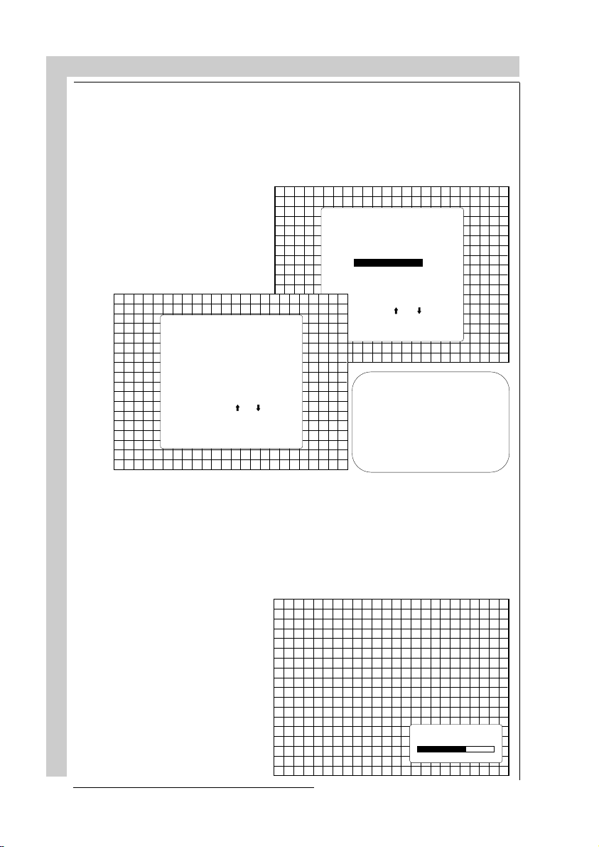
RANDOM ACCESS ADJUSTMENT MODE
Top-Bottom (north-south) Adjustments
Top-Bottom and center adjustments affect only the horizontal lines of the
projected image.
To start up the Top-Bottom and center corrections, follow the next procedure :
Push the control disk up or
down to highlight
TOM (N/S)
menu and then press
TOP-BOT-
on the geometry
ENTER
TOP - BOT TOM
H CENTERLINE BOW
H CENTERLIN E SKEW
TOP BOW
TOP KEYSTONE
BOTTOM BOW
BOTTOM KEYSTONE
Select with o r
then <ENTER>
<EXIT> to return
.
GEOMETRY
H PHASE
RASTER SHIFT
LEFT - RIGHT (E-W)
TOP - BOTTOM (N-S)
H SIZE
V LINEARITY
V SIZE
BLANKING
Select w ith o r
then <ENTER>
<EXIT> to return
will select Top-Bot-
ENTER
tom adjustment menu
returns to random ac-
EXIT
cess adjustment mode menu.
ADJUST
returns to operational
mode
Only the green image is displayed while making top-botton adjustments. The
red and blue images will automatically be corrected in the same manner.
Convergence corrections are automatically disabled for the duration of these
adjustments.
RANDOM ACCESS ADJUSTMENT MODE
The following adjustments can be executed :
- horizontal centerline bow
- horizontal centerline skew
- top bow
- top keystone
- bottom bow
- bottom keystone
All adjustment are indicated
on the screen with the function
name, a bar scale and a number
between 0 and 100. See next
example "H Certerline Bow"
H CENTERLINE
BOW
70
8-18
R5975238 BARCOVISION 701 MULTIMEDIA 070497
Page 95

RANDOM ACCESS ADJUSTMENT MODE
Adjust the next alignments until
the vertical lines are straight.
To enter an alignment, push the
control disk up or down
to highlight a function
and press
activate this function.
Press
EXIT
TOP - BOT TOM
H CENTERLINE BOW
H CENTERLIN E SKEW
TOP KEYSTONE
BOTTOM BOW
BOTTOM KEYSTONE
Select w ith or
then <E NTER>
<EXIT> to return
ENTER
to return.
TOP BOW
to
Corrects for curvature of the horizontal lines in the
middle of the image.
Corrects the tilting of the horizontal lines in the middle
of the image.
Corrects for curvature of the horizontal lines on the upper
side
R5975238 BARCOVISION 701 MULTIMEDIA 070497
Corrects the keystone geometry correction of the hor. lines
on the upper side
Corrects for curvature of the horizontal lines on the lower
side
Corrects the keystone geometry correction of the hor. lines
on the lower side
Correct by pushing
the control disk down
Correct by pushing
the control disk up
RANDOM ACCESS ADJUSTMENT MODE
Page 96

RANDOM ACCESS ADJUSTMENT MODE
Horizontal Size Adjustment
RANDOM ACCESS ADJUSTMENT MODE
Push the control disk up or
down to highlight
the Geometry menu and then
press
ENTER
Adjust the horizontal size by
pushing the control stick to the
right or to the left until the exact
image width is obtained.
Note :
- if the internal # pattern was
selected, this pattern remains on the screen.
- if the genlocked pattern was
H size too
large
.
H SIZE
on
GEOMETRY
H PHASE
RASTER SHIFT
LEFT - RIGHT (E-W)
TOP - BOTTOM (N-S)
H SIZE
V LINEARITY
V SIZE
BLANKING
Select w ith o r
then <ENTER>
<EXIT> to return
will select horizontal size adjust-
ENTER
ment
returns to random access adjustment
EXIT
mode menu.
ADJUST
returns to operational mode
H SIZE
70
8-20
H size too
small
Ideal image size
selected, the external source will be
displayed.
A bar scale and a number indicator give
a visual indication of the horizontal size
adjustment.
Hint : In order to avoid loss of resolution
in the projected image and to ensure
maximum CRT longevity, do not use an
excessively small horizontal size setting.
will return to Geometry
EXIT
R5975238 BARCOVISION 701 MULTIMEDIA 070497
Page 97

RANDOM ACCESS ADJUSTMENT MODE
Vertical Linearity Adjustment
The vertical linearity adjustment function corrects for vertical non-linearities which extend from the center of the image to the top and bottom of
the image.
Push the control disk up or
down to highlight
ITY
on the Geometry menu
and then press
Adjust the vertical linearity with
the control disk until the distances between the horizontal
lines of the set up pattern are
equal.
V LINEAR-
ENTER
.
will select vertical linearity adjust-
ENTER
ment
returns to random access adjustment
EXIT
mode menu.
ADJUST
returns to operational mode
GEOMETRY
H PHASE
RASTER SHIFT
LEFT - RIGHT (E-W)
TOP - BOTTOM (N-S)
H SIZE
V LINEARITY
V SIZE
BLANKING
Select w ith o r
then <ENTER>
<EXIT> to return
R5975238 BARCOVISION 701 MULTIMEDIA 070497
will return to the Geometry menu
EXIT
V
LINEARITY
70
RANDOM ACCESS ADJUSTMENT MODE
Page 98

Vertical Size Adjustment
RANDOM ACCESS ADJUSTMENT MODE
Push the control disk up or
.
V SIZE
on
GEOMETRY
H PHASE
RASTER SHIFT
LEFT - RIGHT (E-W)
TOP - BOTTOM (N-S)
H SIZE
V LINEARITY
V SIZE
BLANKING
Select w ith o r
then <ENTER>
<EXIT> to return
will select vertical size adjustment
ENTER
returns to random access adjustment
EXIT
down to highlight
the Geometry menu and then
press
ENTER
mode menu,.
ADJUST
returns to operational mode
Adjust the vertical size by pushing the control disk up or down
until the exact image height is
obtained.
V SIZE
RANDOM ACCESS ADJUSTMENT MODE
70
Image too
tall
Note :
- If the internal # pattern was selected, this
pattern remains on the screen.
- If the genlocked pattern was selected, the
external source will be displayed.
A bar scale and a number indicator give a
visual indication of the vertical size adjustment.
Hint : In order to avoid loss of resolution in the
Image too
short
projected image and to ensure maximum CRT
longevity, do not use an excessively small
vertical size setting.
8-22
will return to Geometry.
EXIT
R5975238 BARCOVISION 701 MULTIMEDIA 070497
Page 99
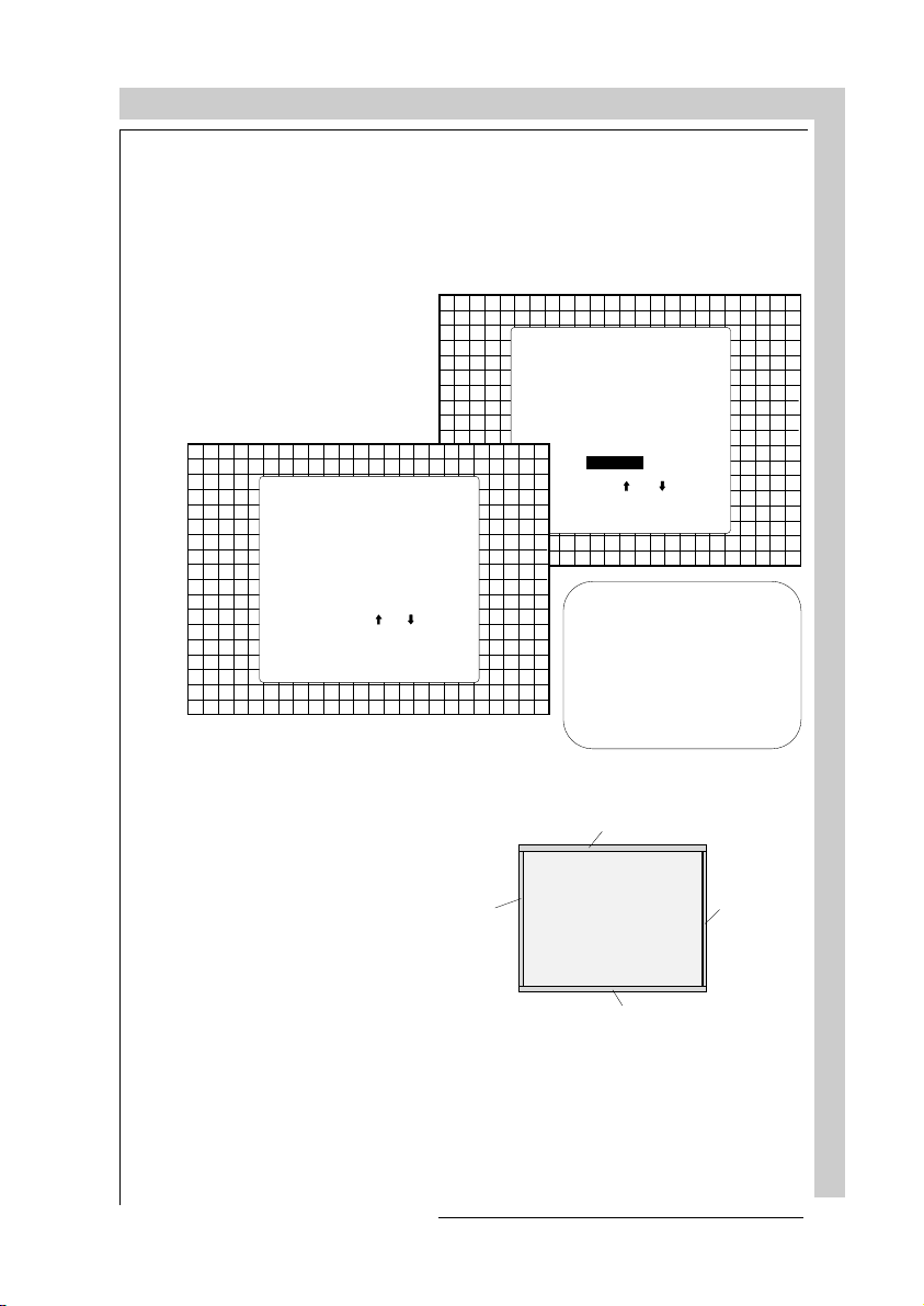
RANDOM ACCESS ADJUSTMENT MODE
Blanking Adjustments
Blanking adjustments affect only the edges of the projected image and are used
to frame the projected image on to the screen and to hide or black out unwanted
information (or noise). A 0% on the bar scale indicates no blanking.
To start up the Blanking adjustments, follow the next procedure :
Push the control disk up or
down to highlight
BLANKING
on the Geometry menu and
then press
ENTER
Select w ith or
then <ENTER>
<EXIT> to return
.
BLANKING
TOP
BOTTOM
LEFT
RIGHT
The following blanking corrections are possible :
- Top blanking
- Bottom blanking
- Left blanking
- Right blanking
Therefore :
Left bl anking
- If the internal # pattern was
selected, this pattern remains
on the screen.
- If the genlocked pattern was
selected, the external source
will be displayed.
GEOMETRY
H PHASE
RASTER SHIFT
LEFT - RIGHT (E-W)
TOP - BOTTOM (N-S)
H SIZE
V LINEARITY
V SIZE
BLANKING
Select w ith o r
then <ENTER>
<EXIT> to return
will select blanking
ENTER
adjustment menu.
returns to random ac-
EXIT
cess adjustment mode
menu.
ADJUST
returns to opera-
tional mode
Top bl anking
Right blanking
Bottom blan ki ng
R5975238 BARCOVISION 701 MULTIMEDIA 070497
RANDOM ACCESS ADJUSTMENT MODE
Page 100

RANDOM ACCESS ADJUSTMENT MODE
Adjust the next blanking alignments until the image is correctly framed or the
unwanted information is blanked out.
To enter a blanking alignment, push the control disk up or down to highlight a
function and press
TOP
LEFT
RIGHT
EXIT
to return.
Press
BLANKING
BOTTOM
Select w ith or
then <ENTER>
<EXIT> to return
to activate this function.
ENTER
Adjustment of the blanking on the of the image
Adjustment of the blanking on the bottom of the image
Correct by pushing the control disk up or
down.
RANDOM ACCESS ADJUSTMENT MODE
8-24
Adjustment of the blanking on the left side.
Adjustment of the blanking on the right side.
Correct by pushing the control disk to the
right or to the left.
R5975238 BARCOVISION 701 MULTIMEDIA 070497
 Loading...