

Page 1

DC Toolset
User guide
For DP ser i es
R59770449/01
15/12/2009
Page 2

Barco nv Media & Entertainment Division
Noordlaan 5, B-8520 Kuurne
Phone: +32 56.36.89.70
Fax: +32 56.36.883.86
E-mail: sales.events@barco.com
Visit us at the web: www.barco.com
PrintedinBelgium
Page 3

Changes
Barco provides this manual ’as is’ without warranty of any kind, either expressed or implied, including but not
limited to the implied warranties or merchantability and fitness for a particular purpose. Barco may make improvements and/or changes to the product(s) and/or the program(s) described in this publication at any time
without notice.
This publication could contain technical inaccuracies or typographical errors. Changes are periodically made
to the information in this publication; these changes are incorporated in new editions of this publication.
Copyright ©
All rights reserved. No part of this document may be copied, reproduced or translated. It shall not otherw
be recorded, transmitted or stored in a retrieval system without the prior written consent of Barco.
ise
Trademarks
Brand and product names mentioned in this manual may be trademarks, registered trademarks or copyrights
of their respective holders. All brand and product names mentioned in this manual serve as comments or
examples and are not to be understood as advertising for the products or their manufacturers.
Software License Agreement
You should carefully read the following terms and conditions before using this software. Your use of this software indicates your acceptance of this license agreement and warranty.
Terms and Conditions:
1. No redistribution of the software is allowed.
2. Reverse-Engineering. You may not reverse engineer, decompile, disassemble or alter anyhow this software
product.
Disclaimer of Warranty:
This software and the accompanying files are sold “as is” and without warranties as to performance or merchantability or any other warranties whether expressed or implied. In no event shall Barco be liable for damage
of any kind, loss of data, loss of profits, business interruption or other pecuniary loss arising directly or indirectly.
Any liability of the seller will be exclusively limited to replacement of the product or refund of purchase price.
Page 4

Page 5

1. INSTALLATION
Overview
• General requirements
• Free download of DC Toolset
• DC Toolset installation
•Startingup
• Uninstall DC Toolset
• About this manual
1.1 General requirements
Before you begin
It assumes you are familiar with the Windows operating system at your site.
System requirements for Microsoft Windows
1. Installation
Minimum hardware specifications :
• PC Pentium III or equivalent, 1 GHz
•512MBRAM
• Free hard disk space: 80 MB
• XGA resolution (1024 x 768)
• Serial communication port and/or Ethernet connection
Software
• Windows 2000, Windows XP Home or Windows XP Professional (recommended)
Recommended hardware specifications :
• PC Pentium IV or equivalent, 2.4 GHz
•512MBRAM
• 140 MB hard disk free space
• SXGA resolution (1280 x 1024) with 32 MB video memory
• Serial communication port
• Ethernet connection
System requirements for Linux
Software
• Any Linux distribution that supports Sun’s Java Runtime Environment v1.5.0 (RedHat 9.0, SuSe 8.2,
Debian/Ubuntu, Mandriva, ...)
Check out the documentation of your favorite distribution to find out if Java 1.5 is supported.
Minimum hardware specifications
• PC Pentium III or equivalent, 1 GHz
•512MbRAM
• Freeharddiskspace: 100MB
• XGA resolution (1024 x 768)
• Ethernet connection (serial connection is not supported)
R59770449 DC TOOLSET 15/12/2009
1
Page 6

1. Installation
Recommended hardware specifications :
• PC Pentium IV or equivalent, 2.4 GHz
•512MBRAM
• 140 MB hard disk free space
• SXGA resolution (1280 x 1024) with 32 Mb video memory
• Serial communication port
• Ethernet connection
Mac OS X
Software
• Apple’s Java SE 5.0 Release 3 or better
• Mac OS X v10.4.2 or better
Minimum system requirements :
•PowerPCG3
•256MBRAM
•10MBdiskspace
• Display with XGA resolution (1024x768)
• Network connection
Recommended system requirements
• PowerPC G5 or Intel Core 2 Duo
• Display with SXGA resolution (1280x1024)
•512MBRAM
• 50MBharddiskfreespace
• Network connection
1.2 Free download of DC Toolset
Overview
The program and all necessary plug-ins can be downloaded for free from Barco’s Partnerzone, (URL:
h
ttps://my.barco.com). Registration is necessary.
If you are not yet registered, click on Sign up My.barco and follow the instructions. With the created login
and password, it is possible to enter the partnerzone where you can download the DC Toolset software
and the device plug-in updates.
When downloading the complete DC Toolset, this software contains already the latest device plug-ins.
It is not necessary to install any other software. A Java virtual machine is included with this download.
1.3 DC Toolset installation
The installation file contains the DC Toolset framework and the availa ble plug-ins.
To install on Microsoft Windows
The process of installing your software involves the following steps:
1. Browse to the directory where the install program is downloaded.
2
R59770449 DC TOOLSET 15/12/2009
Page 7
1. Installation
2. Double click on DCtoolset_Installer.exe .
The installation starts. Depending on the local Internet Explorer settings, it is possible that a warning is
displayed. Just click Run to start the installation.
3. Follow the instructions given in the different install windows.
4. Complete installation is automatic.
Note: A restart of the computer is necessary before the software can be used.
Barco → DC Toolset → DC Toolset item is added to the program list (unless otherwise selected during
the installation).
Only DC Toolset framework is installed. To start using it, first install one or more device
plug-ins. The software will request to install the plug-ins.
To install on MAC OS X
The process of installing your software involves the following steps:
1. Browse to the folder where the downloaded installer zip file is stored.
2. Double click on the zip file to unzip.
3. Double-click on the DCToolset_Installer file.
Theinstallationstarts.
4. Follow the instructions given in the different install windows.
5. The complete installation is done automatically.
Only DC Toolset framework is installed. To start using it, first install one or more device
plug-ins. The software will request to install the plug-ins.
To install on Linux
The process of installing your software involves the following steps:
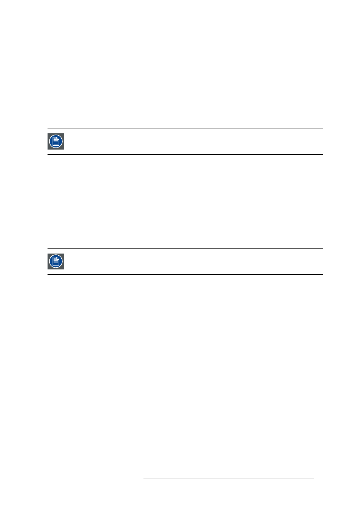
1. Browse to the folder where the downloaded installer file (DCToolset_installer.bin) has been stored.
2. Check if the file is executable. This is done by right clicking on the file and selecting ‘Properties’ from
the popup menu.
3. Select tab Permissions and check if Is executable is enabled. (image 1-1)
4. Double click on the DCtoolset_installer.bin to start the installation.
5. Follow the instructions given in the different install windows.
6. The complete installation is done automatically.
R59770449 DC TOOLSET 15/12/2009
3
Page 8
1. Installation
Image 1-1
File properties
Only DC Toolset framework is installed. To start using it, first install one or more device
plug-ins. The software will request to install the plug-ins.
1.4 Starting up
Launching DC Toolset on Microsoft Windows
To start up the DC Toolset software:
1. Click on Start → Programs and select Barco → DC Toolset→ DC Toolset.
Or,
if a desk top icon is available, double click that desk top icon.
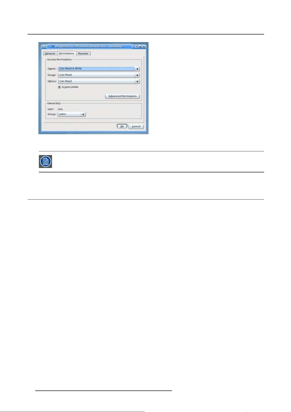
The software starts up. This start up procedure can take a while. First splash screen opens. (image 1-2)
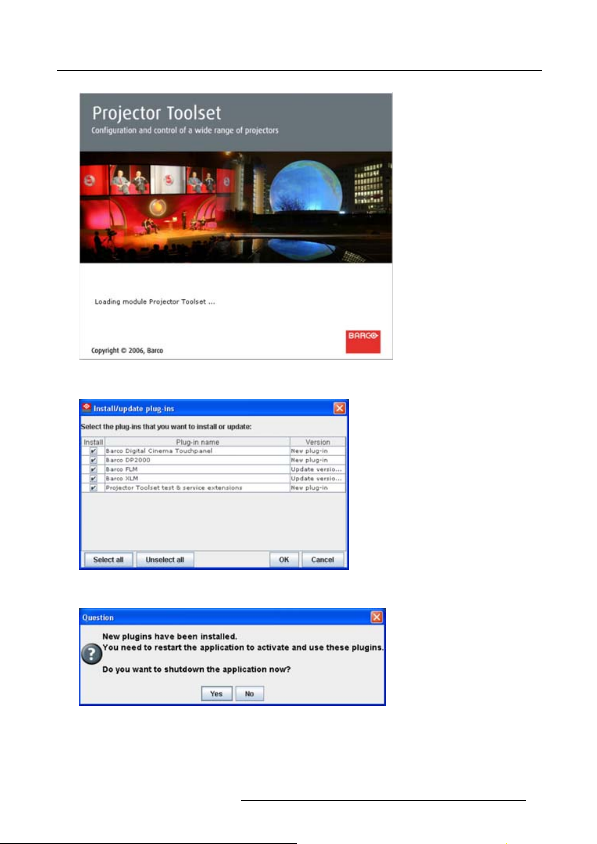
The software starts up with the latest used configurati
downloaded, with overview table of the downloaded plug-ins. All plug-ins in the table are selected by
default. (image 1-3)
2. Unselect the plug-ins which you do not want to install.
Or,
click on Unselect all and then select the plug-ins you want to install.
Select all will check all plug-ins at once.
3. Click OK to install the selected plug-ins.
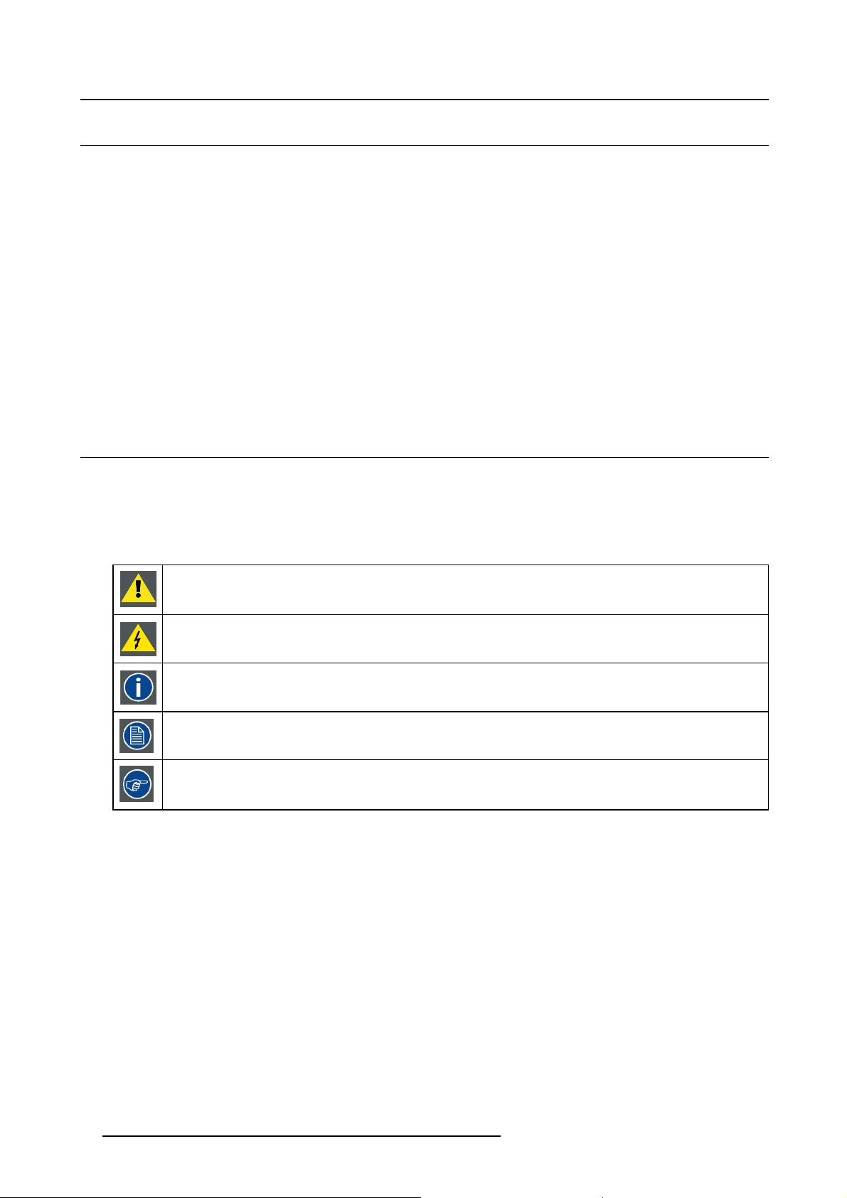
When all plug-ins are installed, a restart message is displayed. (image 1-4)
4. Click Yes to shutdown the application and to restart automatically.
Click No to continue working with the old plug-ins.
on or, if new plug-ins or updated plug-ins are
4
R59770449 DC TOOLSET 15/12/2009
Page 9
1. Installation
Image 1-2
Start up splash screen
Image 1-3
Overview downloaded plug-ins
Image 1-4
Plug-ins ins talled
R59770449 DC TOOLSET 15/12/2009 5
Page 10
1. Installation
1.5 Uninstall DC Toolset
How to uninstall on a Microsoft Windows platform
To uninstall the program, normal Windows functionality can be used to remove a software.
Click on Windows Start, select Settings and open Add/Remove software.
Select the version of DC Toolset which must be removed and click on Remove.
The complete program will be removed from the hard disk.
How to uninstall on a Linux platform
Remove the DC Toolset folder from the home folder.
How to uninstall on a Mac OS X platform
Remove the DC Toolset folder from the application folder in the home folder.
1.6 About this manual
Overview
This Reference manual provides detailed information about the configuration and setup software DC
Toolset. This manual is designed to be a reference tool in your everyday work with DC Toolset.
The following icons are used in the manual :
Caution
Warning
Info, term definition. General info about the term.
Note, gives extra information about the described subject.
Tip, gives extra advice about the described subject.
Images given in the manual are used as illustration. The content of the image can be slightly different with
the real image on the screen, e.g. version numbers, installed modules, etc. .
Typography:
• Clickable menu items or buttons are indicated in bold, e.g. OK
• Menu items are indicated in italic.
• A dialog window is indicated in italic, e.g. Make a new configuration.
• Step related notes, tips, warnings or cautions are printed in italic.
• Procedure related notes, tips, warnings or cautions are printed in bold between 2 lines preceding by
the corresponding icon.
What’s next?
Now that you are familiar with the style of this guide, you are now ready to know more about its modules
and what they can do.
6
R59770449 DC TOOLSET 15/12/2009
Page 11
2. MENUS
Overview
• General
• Menu and button bar
• Main window
• Workspace Explorer
• About DC Toolset
2.1 General
The right mouse button
The right mouse button is used in DC Toolset for direct controls. The use of this button can be handy
throughout the complete software.
Ergonomics
2. Menus
DC Toolset works on the principle of windows with adjustable sizes that can be positioned as you like.
When DC Toolset opens, it displays the main window along with the Menu and button bar. The drop-down
menus include the usual functions of any software (File,etc.) and menus specific for DC Toolset.
The button bar allows switching between the different modules.
An extra Workspace explorer window makes configuration management more easy.
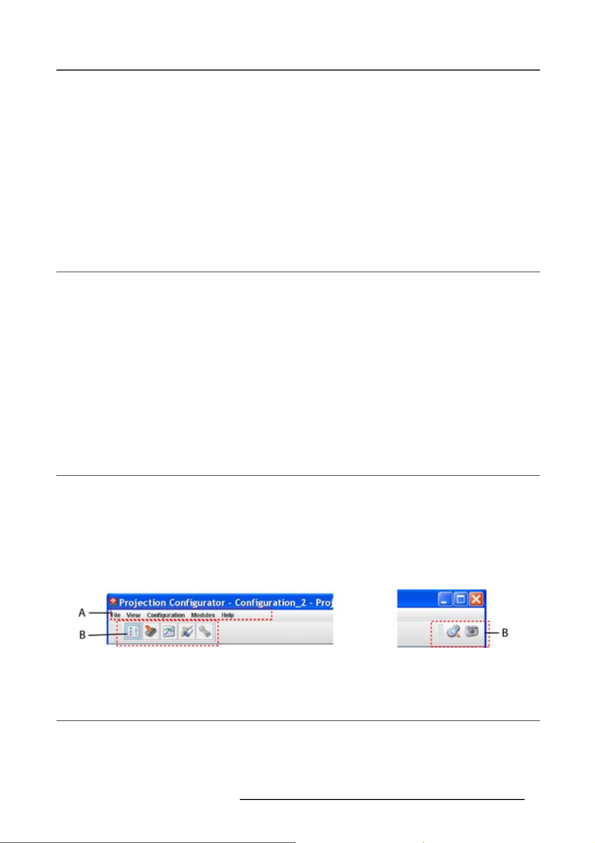
2.2 Menu and button bar
Structure
The menu contains drop down menus accessible by clicking with the mouse on an item. To select an item,
justclickonaniteminthedropdownlist.
The button bar contains on the left side navigation buttons to the different modules and on the right side
manage buttons to the workspace explorer and snapshot function.
To activate a module, click on a navigation button. The window will change accordingly. When activating
some buttons, some extra items will be added to the menu.
Image 2-1
Menu and button bar
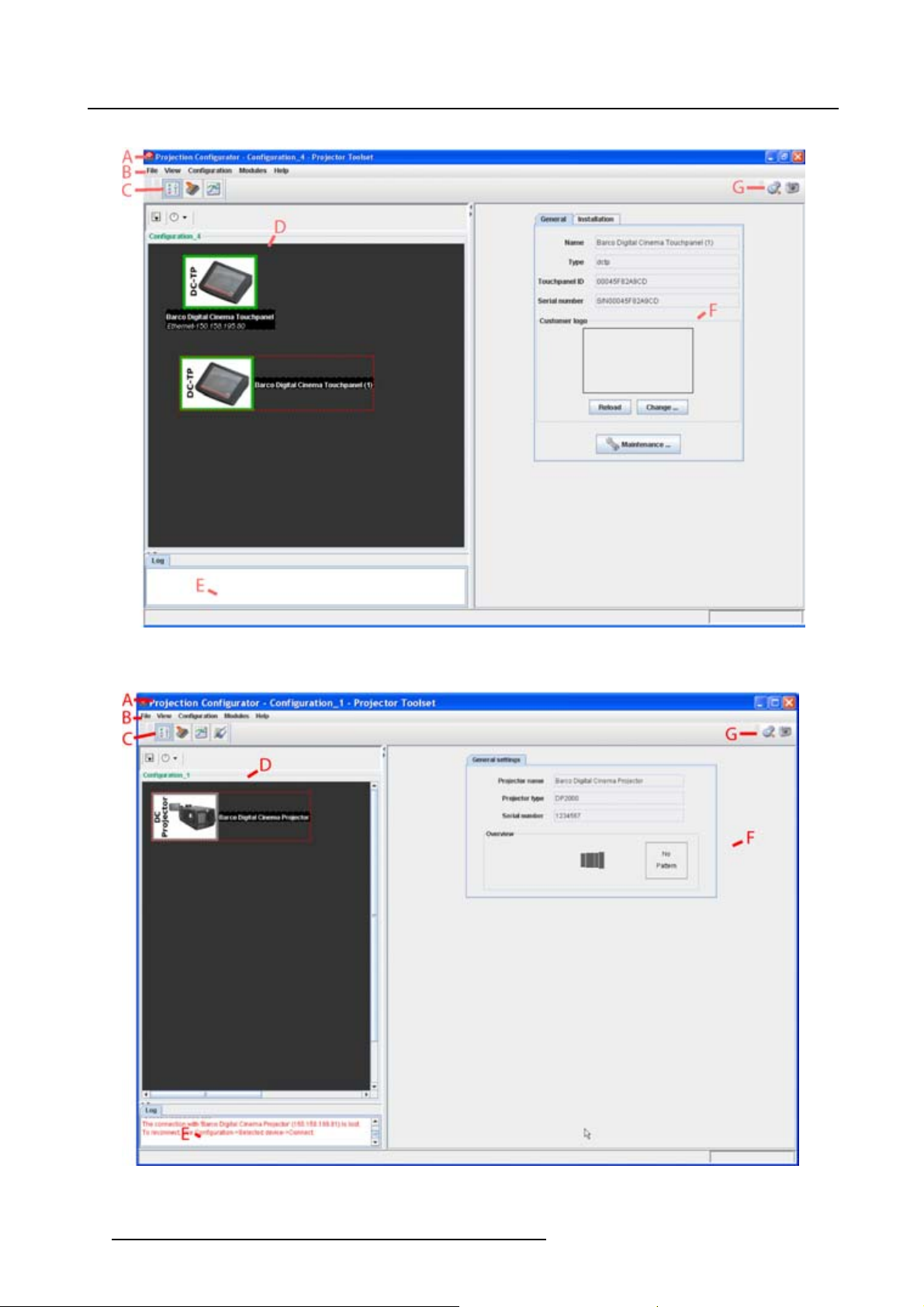
2.3 Main windo w
Overview
The content of the main window changes when a other navigation (module) button is activated, but the
main parts are the same for all modules.
R59770449 DC TOOLSET 15/12/2009
7
Page 12
2. Menus
Image 2-2
Main window indications
Image 2-3
Main window indications
8 R59770449 DC TOOLSET 15/12/2009
Page 13
2. Menus
Indication
A
BMenu
C
D
E
F
G Manage buttons for configurations and snapshots
Description
Window title. Construction of active module - Configuration name
Module navigation buttons
Configuration preview pane
Log window. Can be hidden by the log information button on top of the configuration preview
pane.
Settings pane. Content changes with the selected module button and selected
projector/device.
Tool tip
Some items and or icons show a tool tip when moving the cursor over that item or icon. This tool tip helps
to identify the buttons or items.
Scroll bars
If there is more information available than displayed in a pane, vertical and horizontal scroll bars will be
added to that specific pane. These scroll bars let you move up and down and left and right through the
information in the pane. Vertical scroll bars are the bars on the right side of the pane. Horizontal scroll
bars are the bars at the bottom of the pane.
To use scroll bars, place the cursor on the scroll box, click and hold down the mouse button. Move the
scroll box the entire span of the scroll bar. Notice how you can move and up down in the information in
the pane.
You can also click anywhere above or below (left or right) the scroll box in the empty space. Click once
with the mouse and the scroll bar will make larger leaps in the information.
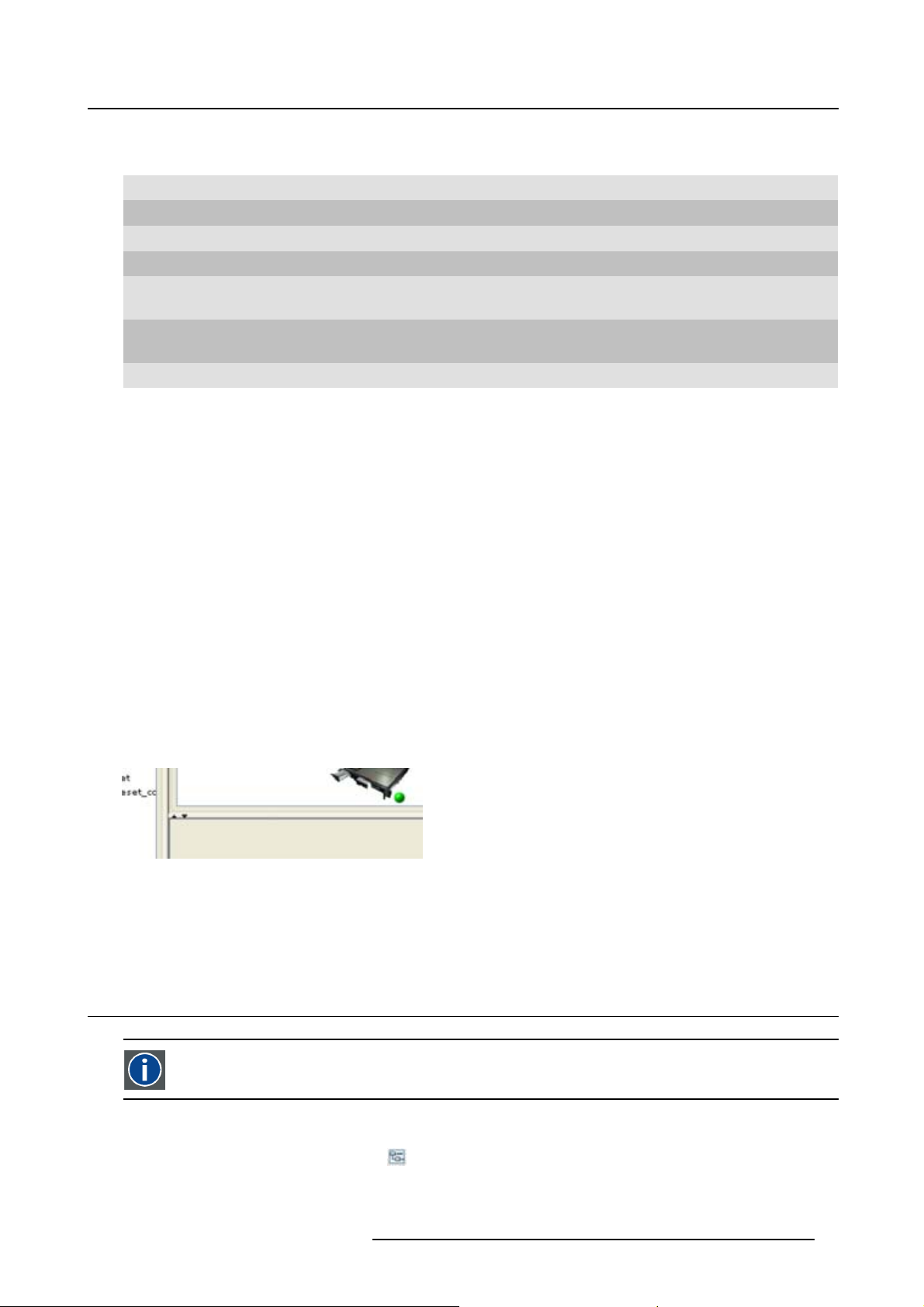
Split bar
The split bar divides the different panes. The position of the split bar is adjustable.
Image 2-4
Split bar
To adjust the position, place the cursor over the split bar separating the panes, so that the two-headed
arrow cursor appears. Click on the two-headed arrow and drag it until the panes are the desired size.
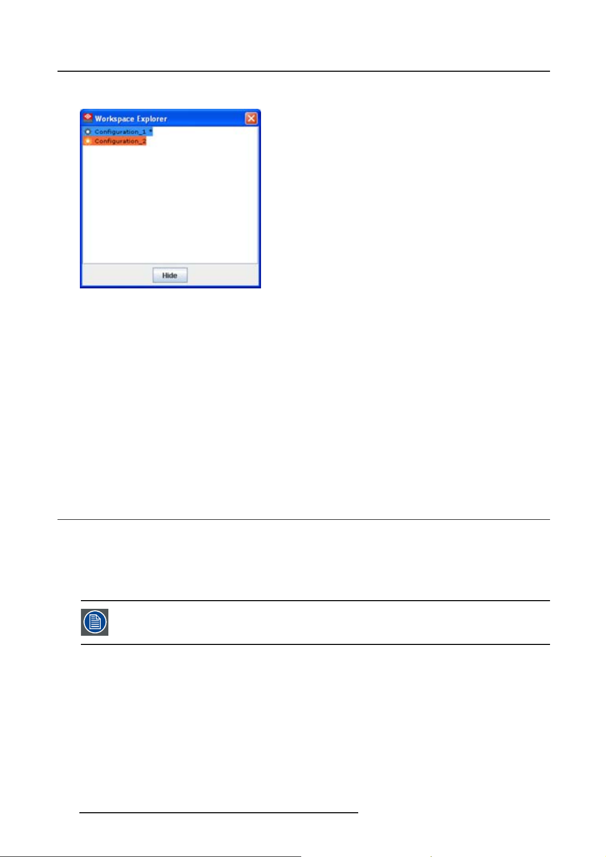
2.4 Workspace Explorer
Workspace explorer
Window to manage the available configurations in the current workspace.
How to display
Click on the workspace explorer icon ( ) on the left top corner or
on the menu, click on View → Workspace explorer or
R59770449 DC TOOLSET 15/12/2009
9
Page 14
2. Menus
press F11.
Image 2-5
Workspace explorer
What can be done
The workspace explorer window gives an overview of the existing Configurations.
To select a configuration, just click on it. The background of the selected configuration changes to blue.
When the same item is open (active) the background remains blue.
When another configuration is selected, the background of this new configuration becomes blue and the
background of the active (open) configuration changes to orange.
To activate (open) another configuration, double click on it. The background becomes blue. All other
configurations will have no background.
An asterisk (*) behind a configuration means that a configuration setting is changed since the last saved
version. A save is necessary to store the changes.
2.5 About DC Toolset
Why?
The about function in the Help menu gives an overview of the used system parameters and the installed
modules. This information can be handy when calling for help.
The images given below are just example images. These images can differ from version to version.
The versions indicated on the illustrations are only given as info and these versions can
be different with the current versions.
How to start up
1. Click Help on the menu and select About (a). (image 2-6)
The About start up dialog box opens (b).
10
R59770449 DC TOOLSET 15/12/2009
Page 15
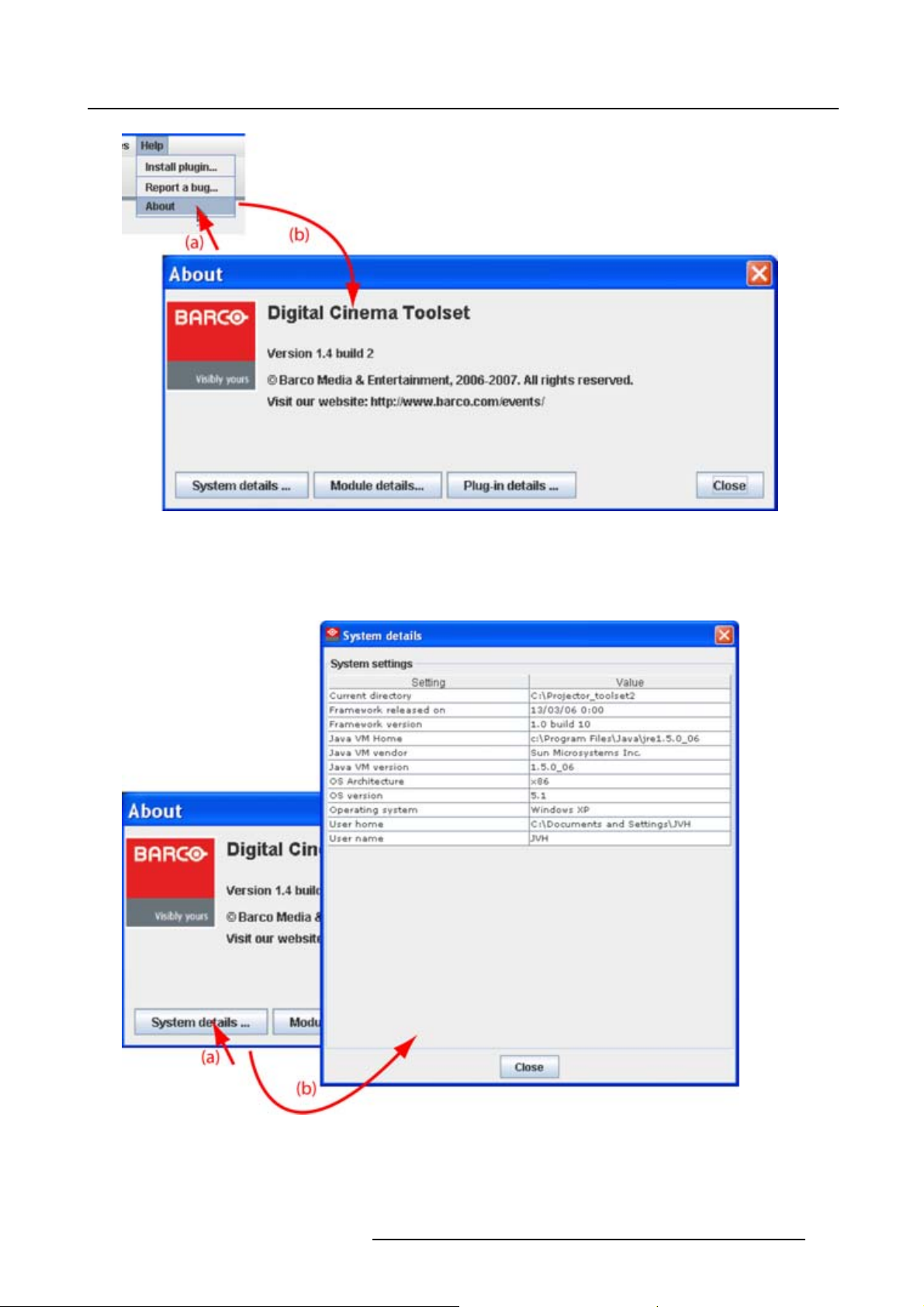
Image 2-6
About window
2. Menus
System details
Click on System details to see the system parameters on which DC Toolset is running.
Image 2-7
System details
R59770449 DC TOOLSET 15/12/2009 11
Page 16
2. Menus
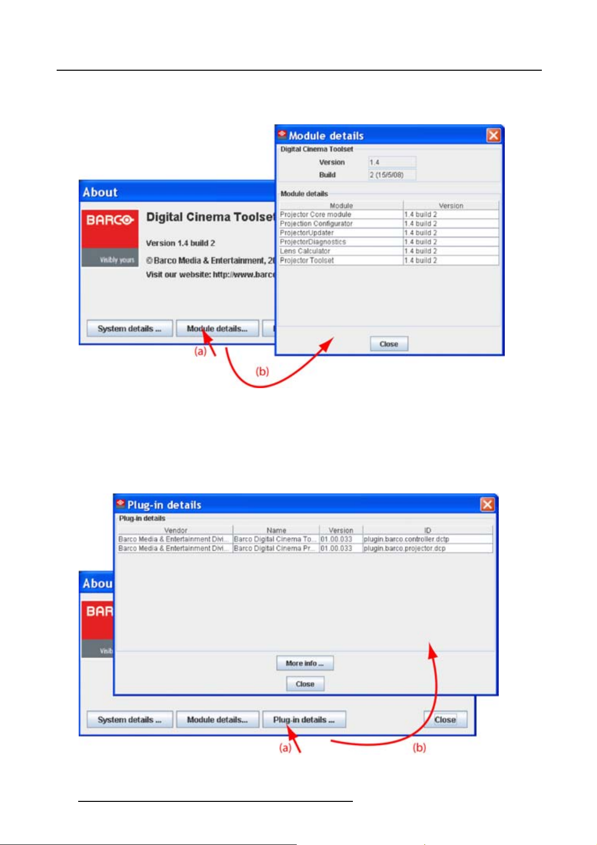
Module details
Click on Module details to get an overview of the installed modules.
Image 2-8
Module details
First of all the software version and the release date are indicated in Module manager.
Module details gives an overview of the installed modules and their version.
Plug-in details
Plug-in details gives an overview of the installed device plug-in together with their version.
Image 2-9
Device plug-ins details
12 R59770449 DC TOOLSET 15/12/2009
Page 17
2. Menus
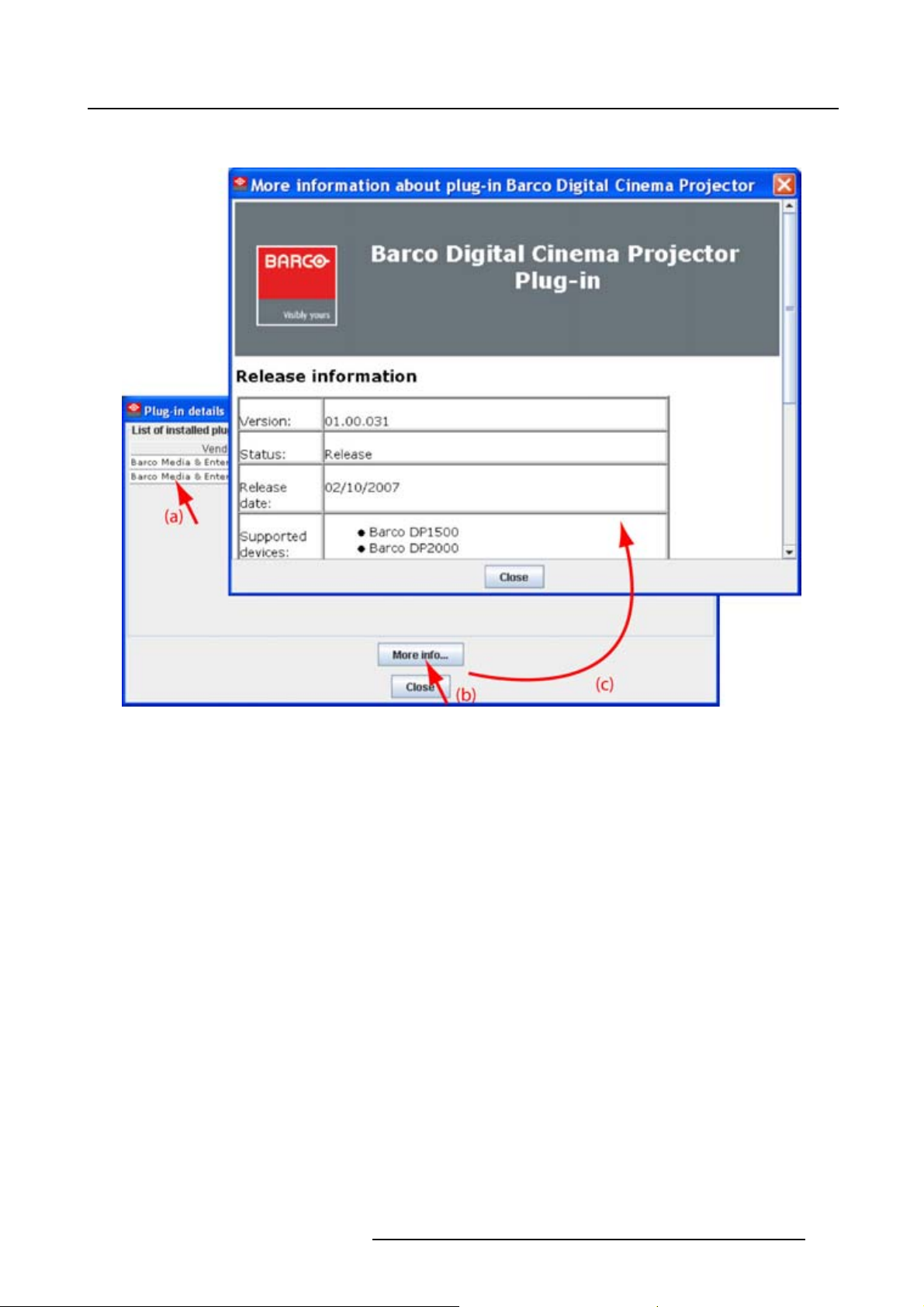
For more info about a device plug-in, click on the desired plug-in to select and then click on More info... .
Image 2-10
More info device plug-in
Release information, plug-in description and license agreement is given.
R59770449 DC TOOLSET 15/12/2009 13
Page 18

2. Menus
14 R59770449 DC TOOLSET 15/12/2009
Page 19
3. Preferences
3. PREFERENCES
Overview
• Introduction
• Start up the preferences
• Access level
• Software Appearance
• Bug report setup
• Logging
• Workspace selection
3.1 Introduction
Overview
Preferences determine the default behavior of the software. Some preferences can be generally set for
the complete software, some others are only for the different plug-in modules.
3.2 Start up the preferences
How to start up ?
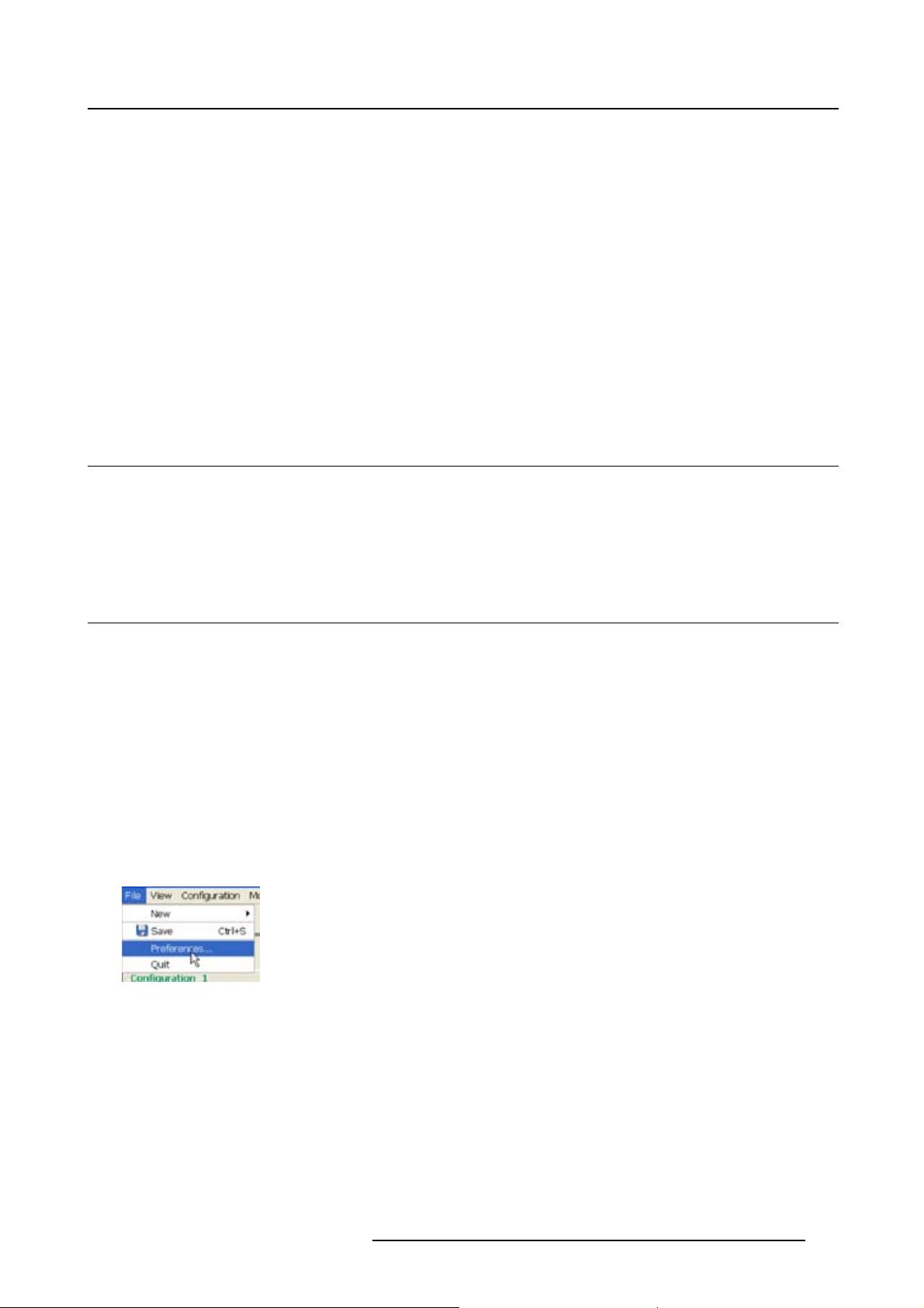
1. Click on File on the menu bar. (image 3-1)
The file menu opens.
2. Select Preferences... .
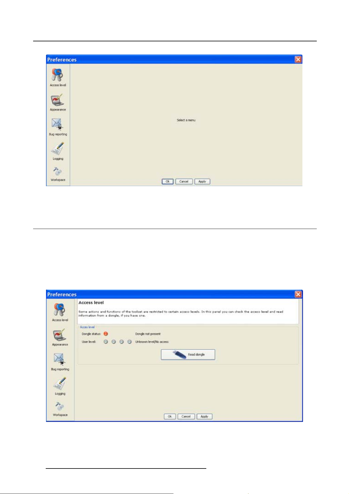
The Preference dialog box opens. (image 3-2)
3. Use the Show all button to display all the preference items. This Show all buttons is available in all
following sub preference windows.
4. Use Apply button to apply a preference change in one of the other module.
Use Cancel to ignore the preference changes.
Use OK to apply the preference changes and to close the window at the same time.
Image 3-1
Select Preferences
R59770449 DC TOOLSET 15/12/2009 15
Page 20
3. Preferences
Image 3-2
Preference window
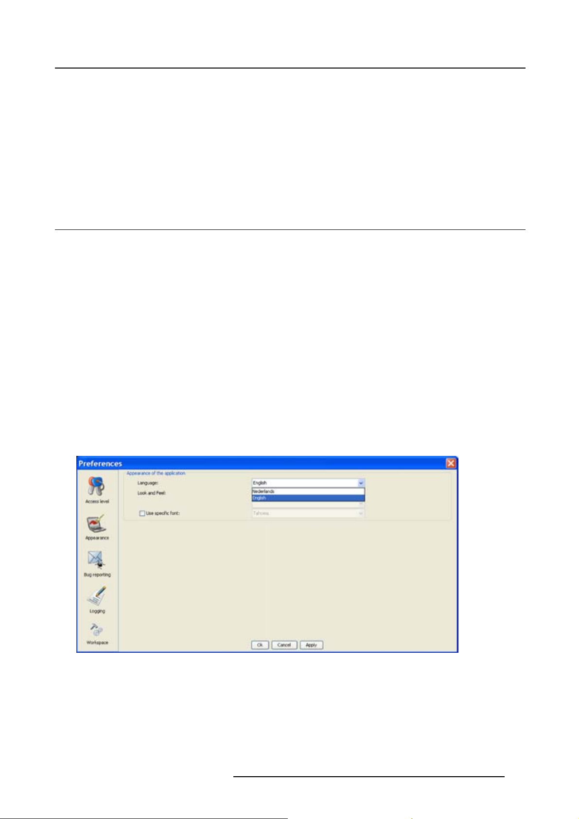
3.3 Access level
What can be done ?
Some actions and functions of the DC Toolset are restricted to certain access levels. In this panel you can
check the access level and read information from a dongle, if you have one.
A dongle is not required to use the normal functions in DC Toolset.
When using DC Toolset without dongle, or as operator, the maintenance function in the Service module
has the same content as the maintenance button in the Configurator module, General tab.
Image 3-3
Access levels
To read out the dongle settings, click on Read dongle. The current level of the inserted dongle is indicated
next to User level.
16
R59770449 DC TOOLSET 15/12/2009
Page 21
3. Preferences
4 different levels are defined:
• operator level
• service technician level
• theatre technician level
• Barco technician level
Each level can access specific functions in the service module. Only the operator level functions are
described in this manual.
3.4 Software Appearance
What can be changed ?
The following items can be changed:
• Language of the software.
• Look and feel of the software.
Language selection
1. Click on Appearance (image 3-2).
The appearance window opens.
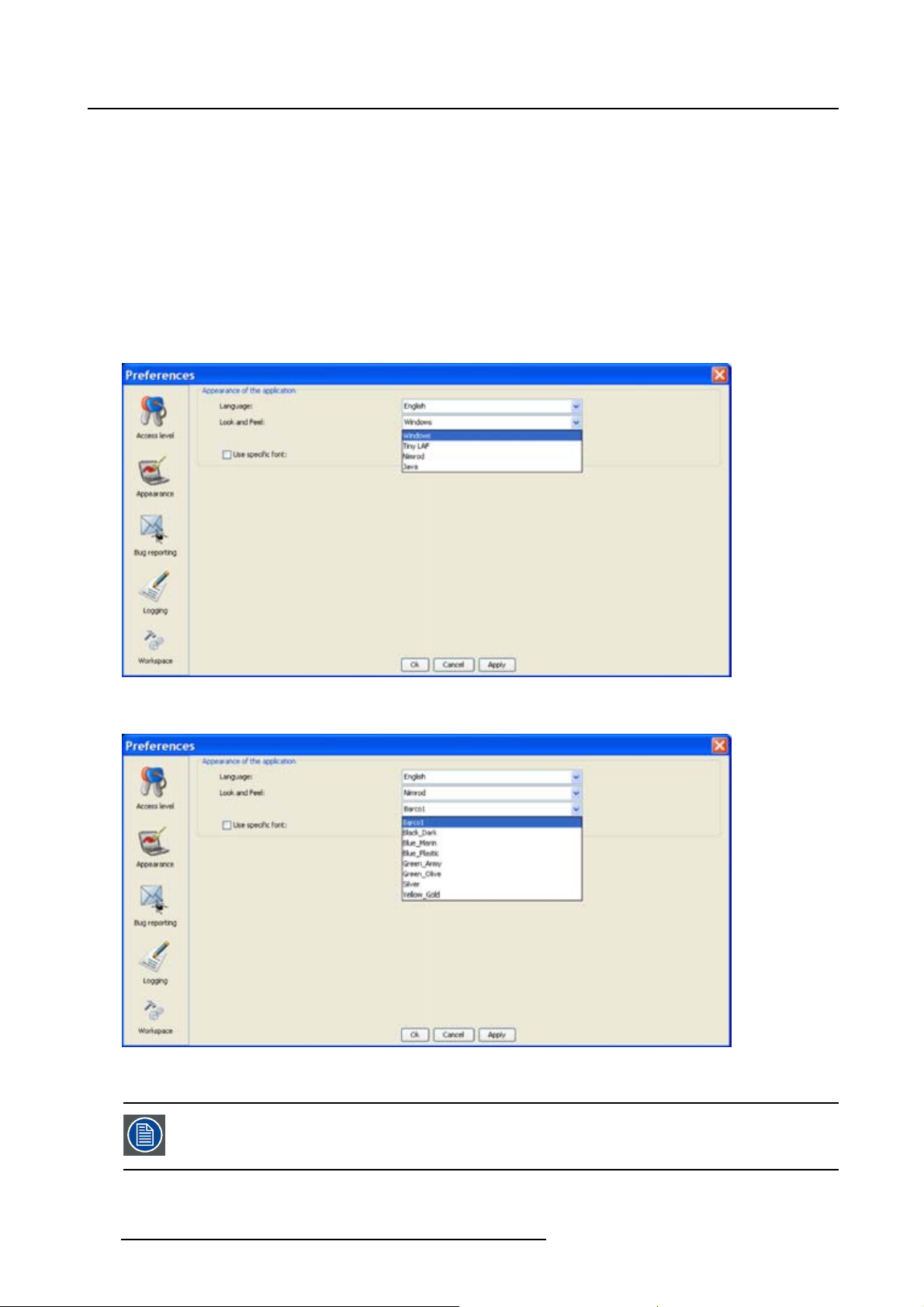
2.ClickonthecomboboxnexttoAppearance of the application.(image3-4)
The possible languages will be displayed.
3. Select the desired language.
4. Click on Apply to confirm the selection.
An info window will be displayed to announce that the language change will take place after restarting
the software.
Image 3-4
Language selection
Look and feel of the software
1. Click on Appearance (image 3-2).
The appearance window opens.
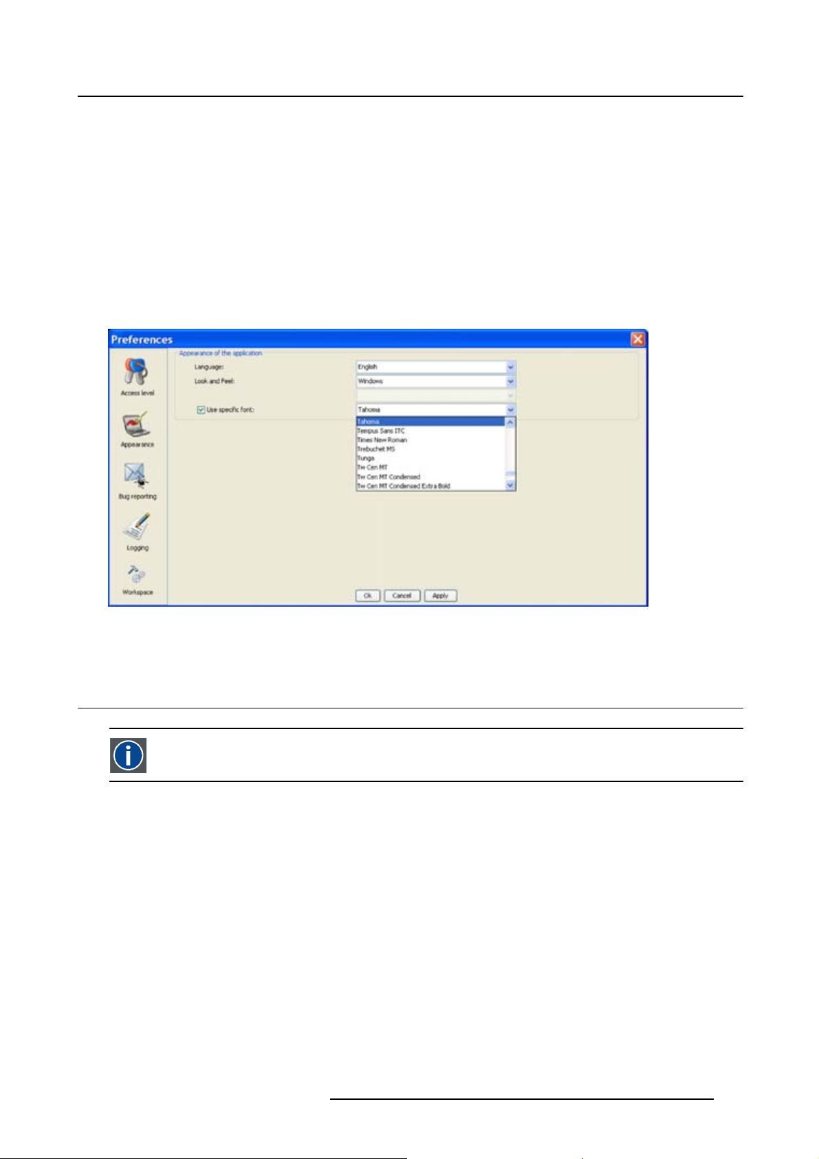
2. Click on the combo box next to Look and Feel. (image 3-5)
R59770449 DC TOOLSET 15/12/2009
17
Page 22
3. Preferences
The possible look and feels will be displayed.
The following are possible:
- Windows
-Java
-Nimrod
-TinyLAF
Nimrod and Tiny LAF are collections of look and feels. If one of both are selected, the second line
becomes available to select a typical look and file out of the collection. (image 3-6)
An info window will be displayed to announce that the look and feel change will take place after restarting
the software.
Image 3-5
Look and feel software
Image 3-6
Look and feel software for collection
Screen shots in this manual are made for a Java look and feel.
18 R59770449 DC TOOLSET 15/12/2009
Page 23
3. Preferences
Use of specific fond
1. Click on Appearance (image 3-2).
The appearance window opens.
2. Check the check box in front of Use specific font. (image 3-7)
The drop down menu becomes available.
3. Click on the drop down box and select the desired font.
4. Click on Apply to confirm the selection.
An info window will be displayed to announce that the look and feel change will take place after restarting
the software.
Image 3-7
Use of specific font
3.5 Bug report setup
SMTP
SMTP (Simple Mail Transfer Protocol) is a TCP/IP protocol used in sending E-mail.
Setup bug report
1. Click on Bug reporting. (image 3-8)
The bug report setup window appears. (image 3-9)
Bug reporting is by default enabled.
2. Fill out the Personal data.
R59770449 DC TOOLSET 15/12/2009
19
Page 24
3. Preferences
This personal data will be incorporated in the bug report so that Barco can contact you.
Personal data contains the following information :
- First name
-Lastname
- Organization
- E-mail address
- Telephone number
- Mobile number
3. Click on Edit mail settings.
The mail settings window opens. (image 3-10)
4. Fill out Your mail account settings.
The following settings should be entered :
- Your E-mail address
- Organization
- Barco’s E-mail address, automatically filled out when installing the software.
5. If you want to receive a copy of the bug report E-mail to Barco, check this check box.
6. Fill out the address of the SMTP mail server.
Tip: Contact your system administrator in your organization to obtain the correct address.
7. Fill out the port of the mail server. Your system administrator can help you. The port is default set on
25.
8. Click OK.
Image 3-8
Bug report selection
20 R59770449 DC TOOLSET 15/12/2009
Page 25

Image 3-9
Bug report setup window
3. Preferences
Image 3-10
Mail setup window
3.6 Logging
Start up
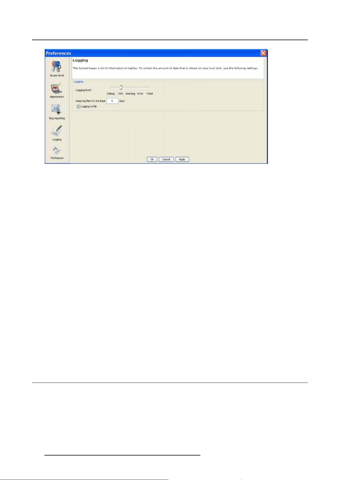
1. Click on Logging.
The logging preferences window opens. (image 3-11)
R59770449 DC TOOLSET 15/12/2009
21
Page 26
3. Preferences
Image 3-11
Logging and debugging preferences
Logging level
Click on the slider bar to set the desired logging level.
The following levels are possible:
• Debug
•Info
• Error
• Warning
•Fatal
Message to log file
The logging about the behavior of the program can be logged in a file. Each time the program is started
anewlogfile is created. The file is saved in a subdirectory log of the DC Toolset install directory. The file
name contains the date and the sequence of start up at that date.
The logging level can be set to limit the number of data. By default, Info level is setup. Other levels are
Debug, Warning, Error and Fatal.
Check the check box in front of Write log messages to file if you want to activate the logging. This is a
preferred setting.
The period a logging must be saved on disk can be set. Default set to 20 days. All logging older than 20
days will be removed.
When the period is set to “0”, only the last created logging will remain on the disk.
To clear the complete logging directory, click once on Clear all.
3.7 Workspace selection
Start up
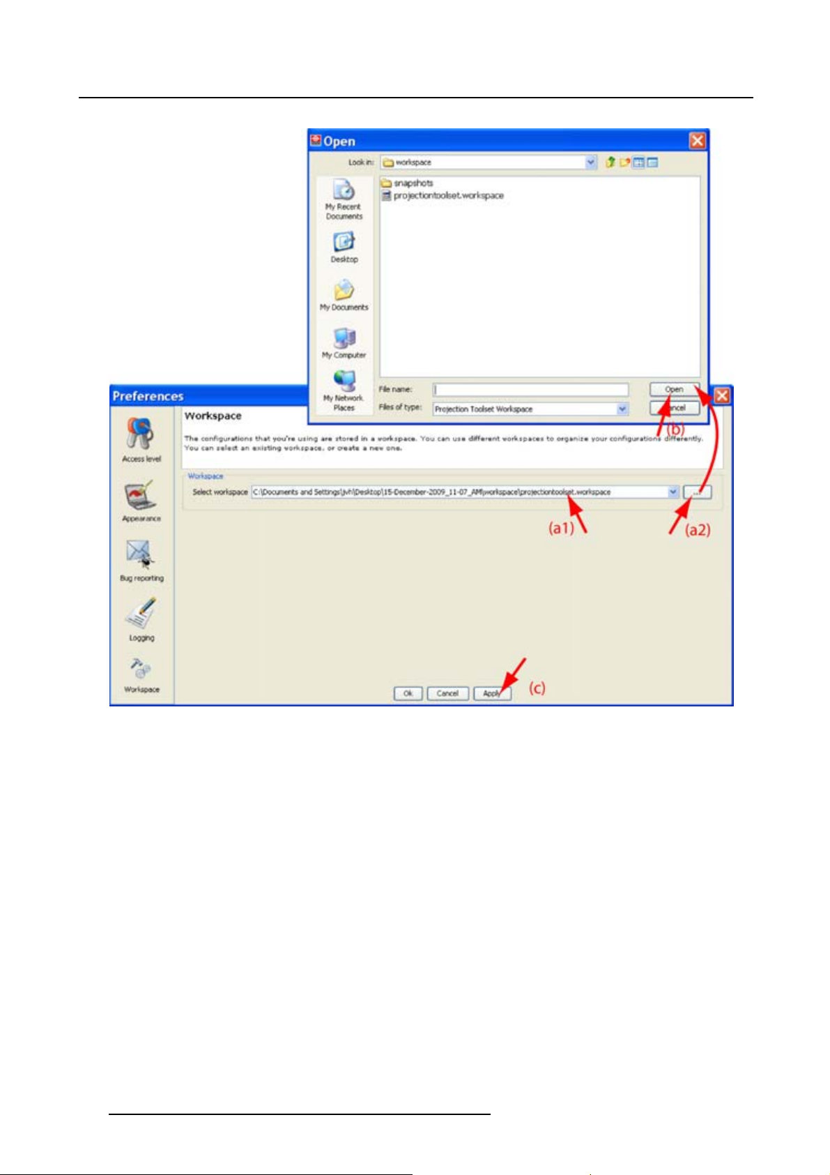
1. Click on Workspace selection. (image 3-12)
The workspace selection dialog box opens.
2. To change to another workspace, click on the drop down box and select the desired workspace. (im-
age 3-13)
22
R59770449 DC TOOLSET 15/12/2009
Page 27

Or,
click on ... to open an Open dialog box (a2).
3. Browse to a workspace or enter a new workspace in the File name field.
4. Click on Open (b).
The current configurations will be closed.
5. Click on Apply to apply the new workspace (c).
3. Preferences
Image 3-12
Select Workspace
preferences
R59770449 DC TOOLSET 15/12/2009 23
Page 28
3. Preferences
Image 3-13
Selecting a workspace
24 R59770449 DC TOOLSET 15/12/2009
Page 29

4. CONFIGURATOR
Overview
• Introduction
•Configurator window
• Create a new configuration
• Adddevicetoaconfiguration via scanning
• Add device to a configuration
• Reconnect a device
• Edit projector properties
•Configuration preview
•Configuration properties
• Preview layout properties
• General Settings
4. Configurator
4.1 Introduction
Overview
The configurator makes it possible to create configurations and to change the settings of each device
separately.
Start up
To start up the configurator, just click on the configurator icon ( ) on the navigation button bar or click
on Modules and select Configurator.
Image 4-1
Configurator start up
4.2 Configurator window
Overview
The configurator window allows to create new configurations and to manage the projectors inside a con-
figuration.
R59770449 DC TOOLSET 15/12/2009
25
Page 30

4. Configurator
4.3 Create a new configuration
Stepstobetaken
1. Click File on the menu and select New → New configuration (a). (image 4-2)
Or,
press Ctrl + N.
The New configuration dialog box opens (b).
2. Fill out a name for the new configuration next to Configuration name. The default name will be Config-
uration_’digit’ (c).
Note: Only the characters a to z, A to Z, 1 to 9 and (, ), _, -, @ or allowed in a name.
When it is the first configuration for this workspace, only the option Create by adding projectors is available.
When there are already configuration available, the option Basedonavailableconfiguration becomes
available
3. Check the radio button of your choice (d).
4. When Basedonavailableconfiguration is checked, click on the combo box and select the configuration
on which the new configuration must be based on (e).
5. Click OK to create the new configuration (f).
Image 4-2
Create new configuration
4.4 Add device to a configuration via scanning
What can be done ?
The network is scanned for possible dev
shows all possible devices on the network and not only the devices with an installed plug-in. Even the
devices which are already in the configuration are in the list.
Multiple devices can be added at the same time. It is not possible to add a device twice or to add a device
for a non installed plug-in.
26
ices which can be added to the configuration. The overview list
R59770449 DC TOOLSET 15/12/2009
Page 31

4. Configurator
The overview window gives the following items:
•Devicetype
• Host name
•IPaddress
• MAC address
• Plug-in name
How to add
1. Click Configuration on the menu and select Add device via scan... (1a). (image 4-3)
Or,
right click on a not connected projector in the preview pane to open the content menu and select Add
device via scan.. .(1b)
Or,
press Insert key.
A network scan is started and a device overview window is displayed (2a, 2b).
2. To select a device, just click on that device (3).
To select multiple devices, hold down the Ctrl button and click on the devices to add to the configuration.
3. Click OK to add the selected devices to the configuration (4).
Only the devices with installed plug-ins and which are not yet in the configuration are added to the
configuration.
Image 4-3
Add devices via scan
R59770449 DC TOOLSET 15/12/2009 27
Page 32

4. Configurator
4.5 Add device to a configuration
This chapter describes how to add a device, projector or touch panel to a configuration
without scanning the complete network for all possible devices.
Overview
• Add device
• General properties
• Set up a Ethernet connection
• Decorator setup
4.5.1 Add device
The possible device types depends on the installed plug-ins.
About adding a device
To make it more easy to find back a device, projector or touch panel while adding it to the software, the
different devices are grouped in categories.
The following categories are available for the moment (depending on the loaded pl
• Digital cinema: contains all supported digital cinema projectors.
• Digital cinema, contains all supported touch panels (DCTP)
ug-ins):
How to add
1. Click Configuration on the menu and select Add (a). (image 4-4)
2. Move the cursor to the right and select the desired category.
3. Move the cursor again to right and select the desired projector.
The Create projector dialog box opens with the selected device type pictograph at the right side (b).
4. Enter the different device properties such as the projector identification, the connection parameters and
projector decorator for the configuration preview.
28
R59770449 DC TOOLSET 15/12/2009
Page 33

4. Configurator
Image 4-4
4.5.2 General properties
Overview
Click on the General tab to open the general properties if not yet open (a).
Image 4-5
General project
or p roperties
R59770449 DC TOOLSET 15/12/2009 29
Page 34

4. Configurator
Projector’s identification
The default display name is Barco followed by the projector type.
This name can be changed to any other name. Click in the name field, select the current name and enter
a new name (b).
Next to the display name, the device type is indicate with the name and a device icon.
Projector status
Indicates the communication status of the projector (c).
• enabled: communication with projector possible
• disabled: no communication with projector possible
4.5.3 Set up a Ethernet connection
Possibilities
To establish a Ethernet connection, the following ways are possible:
• Enter an IP address
• Enter a host name
• Scan the net work for the connected projectors
Via entering an IP address
The IP address known :
1. Select the Connection properties tab (a). (image 4-6)
The right pane changes to the connection setup page.
2. Click on the radio button in front of IP address (b).
3. Enter the IP address (c).
Note: An address contains 4 octets with a maximum value of 255.
4. Click OK to make the connection.
Image 4-6
Make c onnection via entering IP address
Via entering a host name
1. Select the Connection properties tab (a). (image 4-7)
The right pane changes to the connection setup page.
2. Click on the radio button in front of Host name (b).
3. Click in the input field and enter the host name (c).
30
R59770449 DC TOOLSET 15/12/2009
Page 35

4. Click OK to make the connection.
Image 4-7
Create connection via host name
Making a connection via a hos t name is only possible when the host name is known by
the network DNS server.
4. Configurator
Via a device scan
1. Select the Connection properties tab (a). (image 4-8)
The right pane changes to the connection setup page.
2. Click on the Device scan button (b).
The Scanning projector progress bar appears. The broadcast query (based on UDP) for projectors
scans the complete LAN network to detect available projectors on the network. The scanning results
are displayed in the Discover projectors dialog box (c). Only the device of the added plug-ins and the
not yet added devices to the configuration are in the list.
3. If you want to add a single device, click on the desired IP address to select (c) and click Select (d).
If you want to add multiple device, hold down the Ctrl ke
in batch (a). Click Select to add the devices (f).
The number of selected devices is added next to Batch.
4. Click OK to make the connection(s).
y and click on the devices which must be added
R59770449 DC TOOLSET 15/12/2009
31
Page 36

4. Configurator
Image 4-8
Batch connection
4.5.4 Decorator setup
What is a decorator
Decorator information is extra data about the projector which can be displayed in the configuration preview
next to the projector pictograph.
32
R59770449 DC TOOLSET 15/12/2009
Page 37

4. Configurator
Image 4-9
Decorator properties
Decorator position
The extra information can be place in the north, south, east or west of the projector pictograph.
Click on the desired radio button to determine the decorator position.
Decorator content
The following information can be displayed in the configuration preview:
• Projector name
• Connection settings
• Lamp shutter status
•Activefiles
•Devicetype
4.6 Reconnect a device
Via the context menu
1. Right click on a not connected projector in the preview pane. (image 4-10)
A context menu opens.
2. Select Connect.
The device tries to make a connection and to retrieve data. When it is successful the pictograph border
becomes green, the properties are fi lled out. When it is not successful, the border stays gray and a
device not responding message is displayed.
Image 4-10
Connect device via context menu
Via the device properties
1. Select a not connected device in the preview pane. (image 4-11)
R59770449 DC TOOLSET 15/12/2009
33
Page 38

4. Configurator
2. Open the device properties via right click and selecting Properties.
Or,
via click on Configuration onthemenuandselectingSelected device → Properties (a).
Or,
by pressing Ctrl + Enter.
The Device dialog box opens (b).
3. Click on Connection (c).
The Connection tab opens (d).
4. Click on OK (e).
The device tries to make a connection and to retrieve data (f). When it is successful the pictograph
border becomes green, the properties are filled out. When it is not successful, the border stays gray
and a device not responding message is displayed.
Image 4-11
34 R59770449 DC TOOLSET 15/12/2009
Page 39

4.7 Edit projector properties
Via the menu
1. Click on a projector to select (a). (image 4-12)
2. Click Configuration on the menu and select Selected device → Properties (b).
Or,
press Ctrl + Enter.
The Properties dialog box opens (c).
To edit the:
- general properties.
- connection properties.
- decorator.
see Addprojectortoaconfiguration.
4. Configurator
Image 4-12
Edit device properties via menu
Via the context menu
1. Right click on a device graph in the configuration preview. (image 4-13)
A context menu opens.
2. Select Properties.
The Properties dialog box opens.
To edit the:
- general properties.
- connection properties.
- decorator.
see Adddevicetoconfiguration.
R59770449 DC TOOLSET 15/12/2009
35
Page 40

4. Configurator
Image 4-13
Edit de vice properties via right click
4.8 Configuration preview
Device status
The border color around the pictograph indicates the device status.
Green: device is online and there is communication with
Grey: device is offline.
Red: device is online but there are warnings about the use of the device.
Shaded: device is disabled.
the device.
4.9 Configuration properties
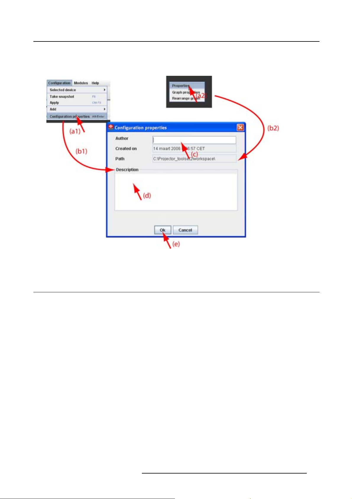
What is available?
The following properties are available:
• author name.
• created on: date and time when the configuration is created (read only).
• path: full path where the configuration is saved (read only).
• description: description which identifies the configuration.
How to change
1. Click Configuration → Configuration Properties (a1).
Or,
right click in the preview pane of the configuration preview, but not on a pictograph (a2). (image 4-14)
The Configuration properties dialog box open
2. To enter an author, click in the input field next to Author and enter the name (c).
36
s(b1,b2).
R59770449 DC TOOLSET 15/12/2009
Page 41
4. Configurator
3. To add a description, click in the Description field and enter a description for the configuration (d).
4. Click OK to save and close the Configuration properties dialog box (e).
Image 4-14
Configuration properties
4.10 Preview layout prop erties
Overview
• Background color
• Background image
• Rearrange pictographs in preview pane
4.10.1 Background color
How to set background color
1. Right click in the preview pane but not on a pictograph (a). (image 4-15)
A context menu opens.
2. Select Graph properties.
The Graph properties dialog box opens (b).
3. Check the check box next to Use background color (c).
4. Click on Select a color.
The Select color dialog box opens.
5. 3 ways are now possible to select a color, represented by a tab in the Select color dialog box.
R59770449 DC TOOLSET 15/12/2009
37
Page 42

4. Configurator
Tab swatc h e s = way1Via the swatches color dialog, step 6.
Tab HSB = way 2 Via the HSB color dialog, step 7.
Tab RGB = way 3 Via the RGB color dialog, step 8.
6. Select the desired color (via swatches = predefined color samples). (image 4-16)
The first selected color will be indicated in Recent. When others are selected for a preview, the color
indication will also be added in the Recent list as first one. Finally, the color selection can be done from
the Recent list or out of the color pallet.
Each time a color is clicked, a preview is given in the preview pane. Continue with step 9.
7. Click on the HSB tab to display the color pallet (HSB = Hue - Saturation - Brightness). (image 4-17)
A color can be selected in 2 ways:
- Slide the slider next to the color gamut until the wanted color in the color pick field is reached, or fill
out the HSB value until the desired color is reached in the pick up field.
- Click in the color field to display the white circle. Drag that circle to the desired tint of the chosen
color.
A preview is given in the preview pane. Continue with step 9.
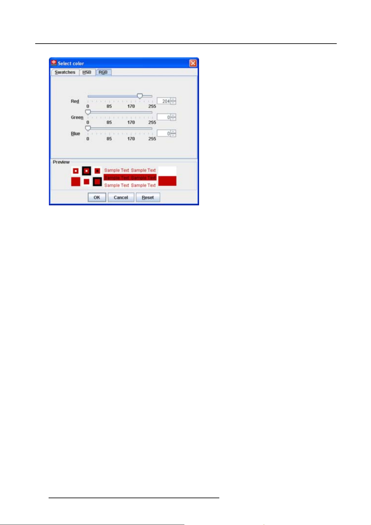
8. Click on RGB tab to display the RGB selection sliders. (image 4-18)
Move the sliders until the desired color is reached, or fill out the RGB values in the input boxes.
A preview is given in the preview pane. Continue with step 9.
9. Click on OK to apply the selected color.
Image 4-15
Set background color
38 R59770449 DC TOOLSET 15/12/2009
Page 43

Image 4-16
Select color via swatches
4. Configurator
Image 4-17
Select c olor via HSB
R59770449 DC TOOLSET 15/12/2009 39
Page 44
4. Configurator
Image 4-18
Select c olor via RGB
4.10.2 Background image
How to set background image
1. Right click in the preview pane but not on a pictograph (a). (image 4-19)
A context menu opens.
2. Select Graph properties.
The Graph properties dialog box opens (b).
3. Check the check box next to Use background image (c).
4. Fill out the complete path to the image (d1) and continue to step 6
Note: Only jpg, gif and png file are allowed.
Or,
click on ... (d2)
An Open dialog box opens (d3)
5. Browse to the desired image (d4) and click Open (d5).
Or,
double click on the desired image.
6. Width an height of the image can be changed by clicking on the up down control next to width and
height (e). To keep the original aspect ratio of the image, activate button Keep aspect ratio (f).
7. To tile the image over the complete canvas, check the check box before Tile image (g).
8. Set transparency level by clicking on the slider and dragging to the desired location (h)
Or,
by clicking in the input field next to the slider and entering the desired value with the keyboard.
40
R59770449 DC TOOLSET 15/12/2009
Page 45

4. Configurator
Image 4-19
Set background image
4.10.3 Rearrange pictographs in preview pane
How to rearrange
1. Right click in the preview pane but not on a pictograph. (image 4-20)
A context menu opens.
2. Select Rearrange graphs.
The pictographs are rearranged in the preview pane.
Image 4-20
Rearrange pictographs
R59770449 DC TOOLSET 15/12/2009 41
Page 46

4. Configurator
4.11 G eneral S ettin gs
Overview
Image 4-21
General settings DC projector
Image 4-22
General settings Touch panel
The General Settings pane is an read only pane and gives information about:
• device name
•devicetype
• serial number
• overview of device status
For a touch panel, an extra Maintenance button is available.
42
R59770449 DC TOOLSET 15/12/2009
Page 47

5. General device settings Touch panel
5. GENERAL DEVICE SETTINGS TOUCH
PANEL
5.1 Start up and overview
How to start up
1. Click on the desired projector graph to display the touch panel properties. (image 5-1)
2. If the General settings are not open, click on the General tab.
The general settings are displayed.
Image 5-1
General settings
Overview
The following items are given as read only values:
• Name of the device
•Devicetype
• Touch panel ID
• Serial number
The following items can be changed or ac
• Customer logo on the touch panel
• Maintenance items:
- Restart the application
- Re-calibrate the touch screen
- Add a temporary account to the touch panel
R59770449 DC TOOLSET 15/12/2009
cessed by the customer:
43
Page 48

5. General device settings Touch panel
5.2 Add a custom logo in touch panel
About a custom logo
The touch panel software allows to place a custom logo on the upper left corner of the touch screen. The
software provides an area of 90 x 90 pixels. Any image larger than 90 x 90 pixels will be proportionally
scaled to match inside this area. The file must be a bitmap file (bmp, jpeg, jpg, png, ...).
Current active logo
To display the current active logo in DC Toolset, click on Reload.Thefile is downloaded from the touch
panel and a preview will be shown within the rectangular square.
Image 5-2
Reload current logo
How to add or change a logo
1. Click on Change... (a). (image 5-3)
The Change customer logo window opens (b).
2. Fill out the path and file name (c1) and click OK
Or,
click on Load (c2).
A browse window opens (d).
3. Browse to the desired file (e) and click Open (f).
A preview is shown in the Change customer logo window (g). (image 5-4)
4. If this is the file, click OK (h).
An upload question is displayed (i).
5. Click Yes to upload the image to the touch panel (j).
When the upload is finished (k), an info window is displayed with the message : New logo is set in touch
panel”.
6. Click OK to continue (l).
44
R59770449 DC TOOLSET 15/12/2009
Page 49

5. General device settings Touch panel
Image 5-3
Change logo
R59770449 DC TOOLSET 15/12/2009 45
Page 50

5. General device settings Touch panel
Image 5-4
Change logo
5.3 Temporary account
Why creating a temporary account
If there are no root user defined on the touch panel or if these root users cannot be activated then it still
possible to create a temporary root user via DC Toolset. This user has access to all functions and can
create a new root user for the touch panel.
This temporary account is mostly used for service purposes and will be deleted when the service actions
are finished.
How to create a temporary account
1. Within the General settings, click on Maintenance (a). (image 5-5)
The Touch panel controls window opens (b).
2. Click inside the input field next to Authorization password (c) and enter the authorization code.
3. Click on Authorize now (d).
A user creation window opens where it is possible to create a temporary user and password.
46
R59770449 DC TOOLSET 15/12/2009
Page 51

5. General device settings Touch panel
Image 5-5
Create temporary account
R59770449 DC TOOLSET 15/12/2009 47
Page 52

5. General device settings Touch panel
48 R59770449 DC TOOLSET 15/12/2009
Page 53

6. General device settings DC projector
6. GENERAL DEVICE SETTINGS DC
PROJECTOR
6.1 Start up and overview
How to start up
1. Click on the desired projector graph to display the projector general settings. (image 6-1)
Image 6-1
Overview
The following items are given as read only values:
• Name of the projector
• Projector type
• Serial number
• Overview of the projector status
R59770449 DC TOOLSET 15/12/2009
49
Page 54

6. General device settings DC projector
50 R59770449 DC TOOLSET 15/12/2009
Page 55

7. INSTALLATION
Only for Touch panels.
Overview
•Startingupthefile management
• Create new folder
• Delete a file or folder
• Download a file from the touch panel
• Upload a file on the touch panel
7.1 Startingupthefile management
7. Installation
How to start up
1. Click on the Installation tab to display the installation functions (a). (image 7-1)
2. Click on File Management (b).
The File management window opens (c).
Image 7-1
File management
R59770449 DC TOOLSET 15/12/2009 51
Page 56

7. Installation
About the file manager
Only user files can be displayed or manipulated in the file manager.
The following functions are available:
(1) Reload file list, to update the content of the file manager.
(2) Create new folder
(3) Delete file or folder
(4) Download selected file
(5) Upload file
7.2 Create new folder
What can be done ?
A new folder can be created on the touch panel’s operating system.
How to create a folder
1. Click on the New folder icon (a). (image 7-2)
The Create new folder window opens.
2. Click in the input field and enter a name for the folder.
3. Click OK to create the folder.
Image 7-2
Create new folder
7.3 Delete a file or folder
How to delete
1. Click on a file or folder to select. (image 7-3)
52
R59770449 DC TOOLSET 15/12/2009
Page 57

2. Click on the Delete icon.
Image 7-3
Delete file or folder
7. Installation
7.4 Download a file from the touch panel
What can be done ?
Any user file stored on the touch panel can be downloaded to the computer.
How to download
1. Browse in the File management window to the desired file or folder on the touch panel and click on it
to select (a). (image 7-4)
2. Click on the Download icon (b).
The Download window opens (c).
3. Click in the input field and fill out a location for the file (d1)
Or,
click on ... button (d2) and browse to the desired location and click Open.
4. Check or uncheck properties for handling the file (e).
- Overwriting or not overwriting existing files.
- Recurse into folders: all files and sub folders are downloaded.
- Close the window when the download is finished.
5. Click OK to start the download (f).
When the download is finished a message appears. Click Close to continue (g).
R59770449 DC TOOLSET 15/12/2009
53
Page 58

7. Installation
Image 7-4
Download file
7.5 Upload a fil e on the touch panel
What can be done ?
A file can be transferred from the computer to the touch panel and stored as user file.
How to upload
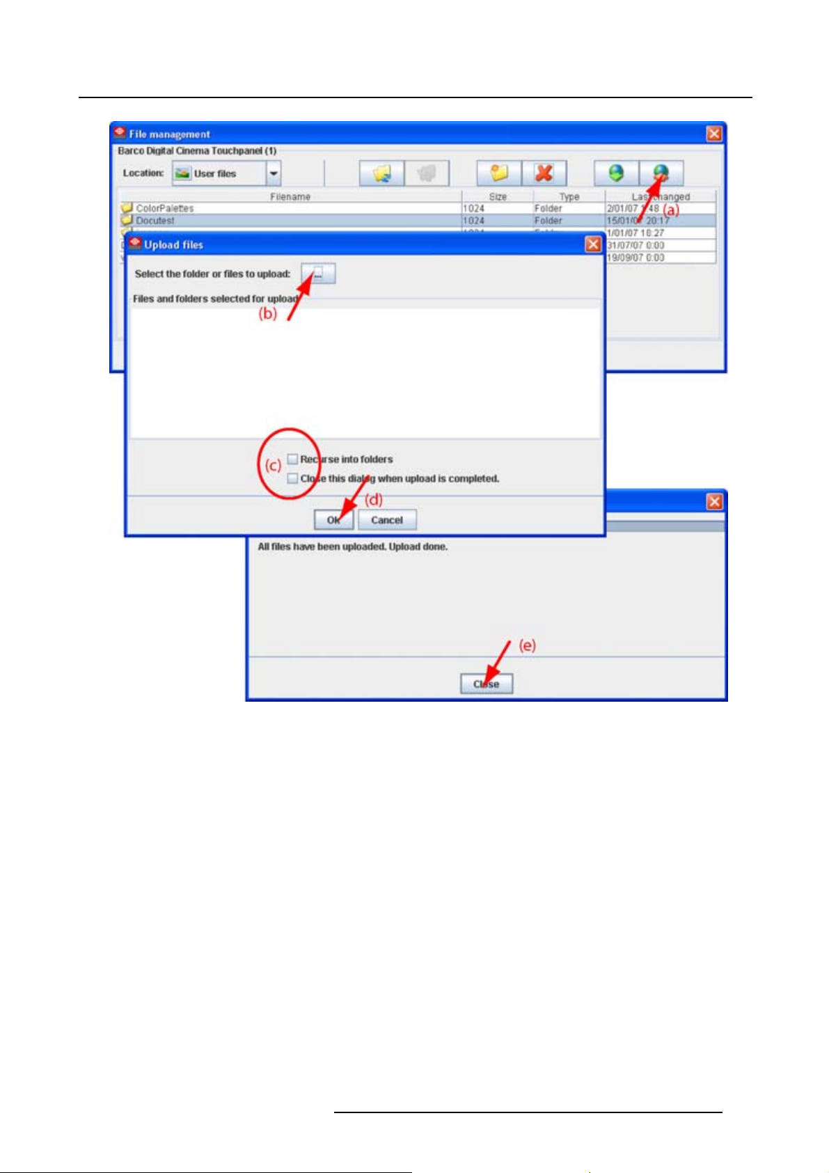
1. Click on the Upload icon (a). (image 7-5)
The Upload files window opens.
2. Click on the ... button (b) to open the browse window.
3. Browse to the desired file or folder and click Open.
The full path is displayed in Files and folders selected for upload.
4. Check or uncheck properties for h
- Recurse into folder : all files and sub folders are uploaded.
- Close the window when the upload is finished.
5. Click OK to start the upload (d).
andling the file (c).
When the upload is finished, a message is displayed.
6. Click Close to continue (e).
54
R59770449 DC TOOLSET 15/12/2009
Page 59
7. Installation
Image 7-5
Upload a file or folder
R59770449 DC TOOLSET 15/12/2009 55
Page 60

7. Installation
56 R59770449 DC TOOLSET 15/12/2009
Page 61

8. UPDATE MODULE
Overview
• Introduction
• Update a Digital cinema projector
• Updating a touch panel
•Versioninfo
8.1 Introduction
Overview
The firmware of the projector/device can be updated with DC Toolset.
8. Update module
Free downloadable packages can be found on Barco’s Partnerzone, (URL: h
tration is necessary.
If you are not yet registered, click on Sign up my.barco and follow the instructions. With the created lo-
gin and password, it is possible to enter the Partnerzone where you can download the desired software
upgrades.
Updating of multiple projectors at the same time is possible. When the update is started on one projector/device and running, it is possible to start up an update on second projector/device.
ttps://my.barco.com). Regis-
Preparations
The downloaded file is a zip file. Unzip this file before continuing.
Start up
To start up the Updater, just click on the Update icon ( ) on the navigation button bar or click on Modules and select Updater.
Image 8-1
Start U pdater module
8.2 Update a Digital cinema projector
How to update
1. Select the device to update in the device preview pane.
2. Click the Update.icon (
Device ID, serial number and communication info is given.
3. Click on Update now to start up the update wi
4. To select the update folder, click on the folder icon (3) to open the browse dialog box and browse to the
directory where the update package is stored. Click on Open.
R59770449 DC TOOLSET 15/12/2009
) in the menu bar.
zard (1). (image 8-2)
57
Page 62

8. Update module
5. Browse to the to the directory where the update package is stored.
The available packages for the connected projector are listed.
- update package: use this package to upgrade the projector if the version info of the projector can be
retrievedinanormalway.
6. Select the desired update (4) and click Select (5).
The package is loaded in the update window (6). If you want to see more information about the update,
click on More information ... (7) to display the release info. (image 8-3)
Information will be retrieved from the projector. An overview will be displayed with the current software
version next to the version in the update package. (image 8-4)
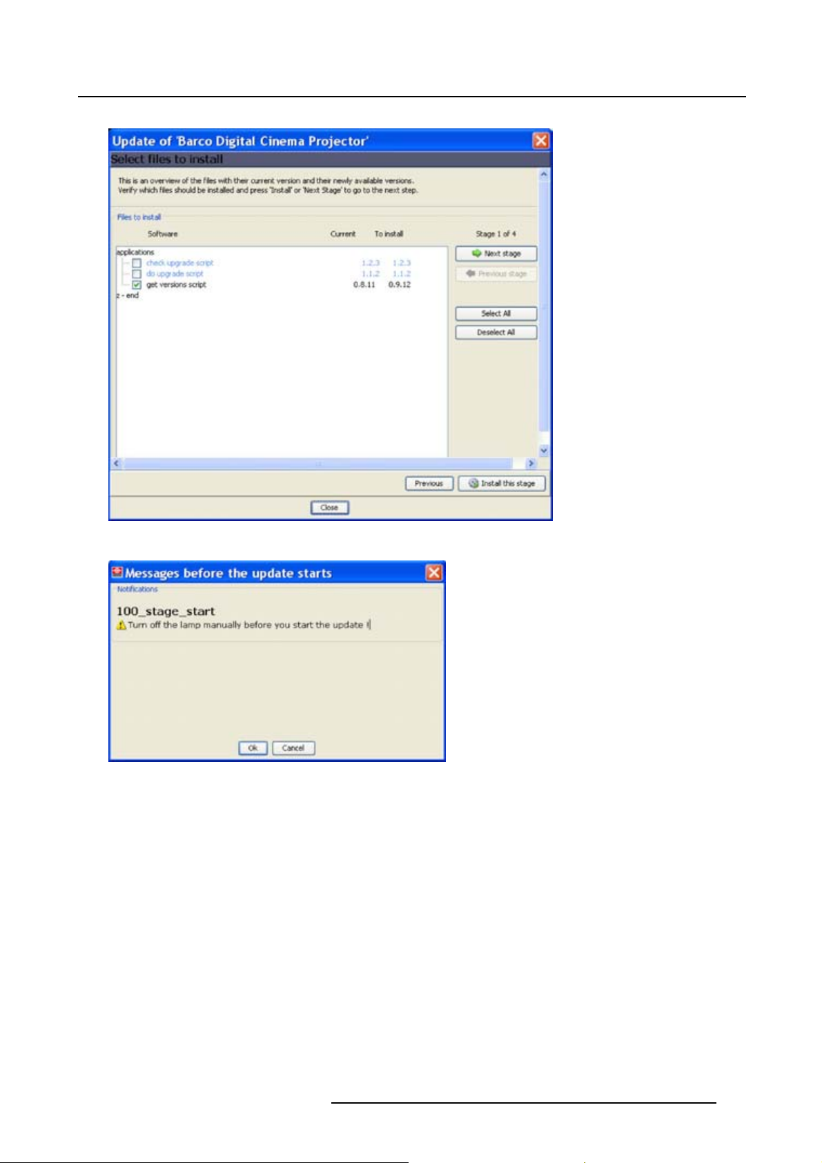
7. To continue updating, double click on the item that you want to upgrade. Multiple selection is possible
by clicking on several items.
Click Install the stage.(image8-5)
If you click Next stage while files are selected a message is displayed to warn that the files are not yet
installed.
If you want to return to the current stage to install the files first, click No. Otherwise click Yes.
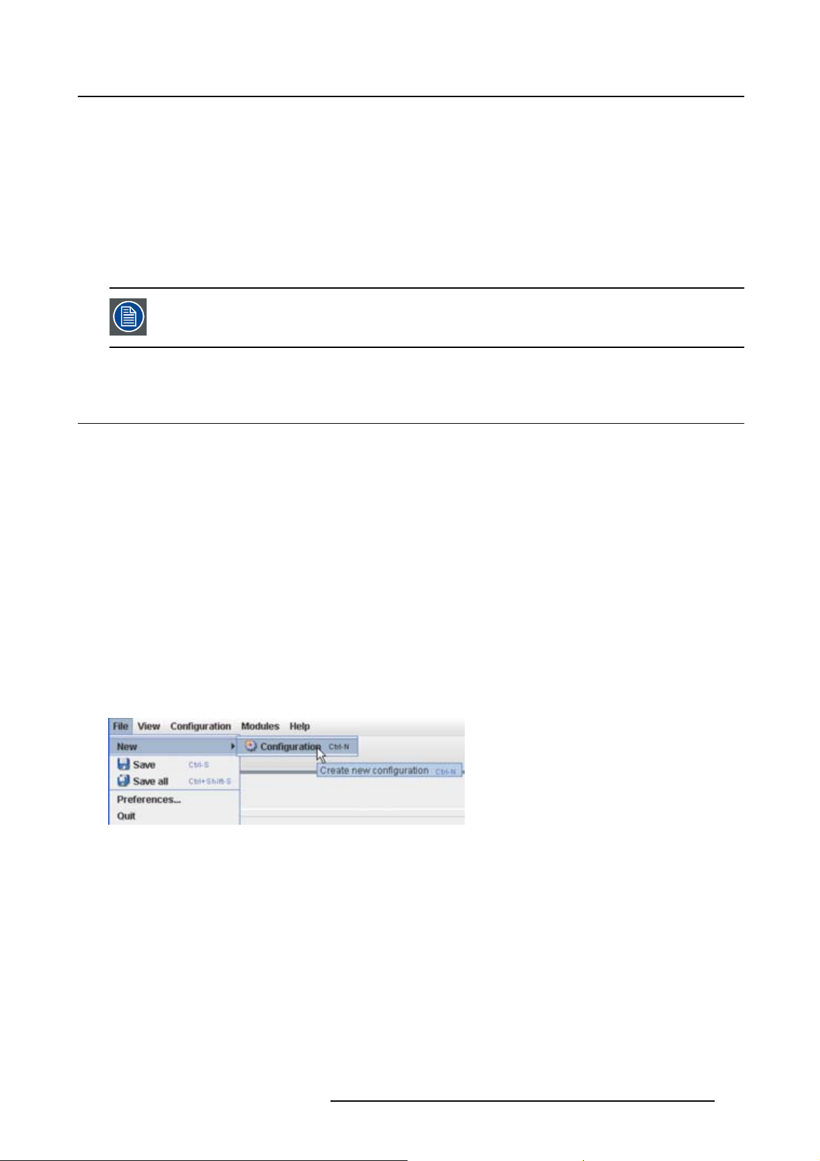
When I nstall this stage is pressed, a notification is given to turn off the lamp manually before starting
the update. (image 8-6)
8. When the lamp is turned off, click OK.
An overview window is given. Click in Install to start the installation. (image 8-7)
9. Click Install to start the update.
A progress bar is displayed.
When finished, version information is retrieved for the next step.
10.If your want to update files in the second stage, double click on the desired files and click OK.(image 8-8)
Anotification is given to turn off the lamp manually before starting.
To skip this step, click Next step.
To return to the previous step, click Previous step.
If OK is pressed, the update starts. A message will be displayed to reboot the projector.
Reboot the projector and click then OK.
When finished, version information is retrieved for the next step.
11.If an update is needed of any of the applications, double click on the files that need an update and click
OK to start the update. (image 8-9)
A notification is given to turn off the lamp manually before starting the update.
To return toe the previous step, click Previous step.
When finished, version information is retrieved for the next step.
12.If an update is needed of any of the applications, double click on the files that need an update and click
OK to start the update. (image 8-10)
To return toe the previous step, click Previous step.
The update will be finalized.
58 R59770449 DC TOOLSET 15/12/2009
Page 63

8. Update module
Image 8-2
R59770449 DC TOOLSET 15/12/2009 59
Page 64

8. Update module
Image 8-3
Image 8-4
More information
60 R59770449 DC TOOLSET 15/12/2009
Page 65
8. Update module
Image 8-5
Image 8-6
Notification
R59770449 DC TOOLSET 15/12/2009 61
Page 66

8. Update module
Image 8-7
Overview window
Image 8-8
Update stage 2
62 R59770449 DC TOOLSET 15/12/2009
Page 67

8. Update module
Image 8-9
Update stage 3
Image 8-10
Update stage 4
R59770449 DC TOOLSET 15/12/2009 63
Page 68

8. Update module
8.3 Updating a touch panel
How to update
1. Click on Update.
Device ID, serial number and communication info is given.
2. Click on Update now to start up the update wizard. (image 8-11)
3. If the indicated folder (a) is not the location where the update package is stored, click on ... (b) to open
the browse dialog box and browse to the directory where the update package is stored. Click on Open.
The available packages are listed.
- update package: use this package to upgrade the projector if the version info of the projector can be
retrievedinanormalway.
4. Select the desired update (c) and click Next (e).
If you want to see more information about the update, click on More information ... (d) to display the
release info.
Information will be retrieved from the projector. An overview will be displayed with the current software
version next to the version in the update package.
5. Double click on the item that you want to upgrade. Multiple selection is possible by clicking on several
items.
Click Next to continue.
An overview with the selected items will be displayed.
6. Click Install to start the update.
The connection will be prepared. A progress bar is displayed on the device pictograph in the preview
pane.
The update window can now be closed. A new update of another device can be started.
To get an overview of the update status of a previous started update, double click on the pictograph of
that device. The update status is displayed in the properties pane.
When the installation is finished, an info window is displayed.
64
R59770449 DC TOOLSET 15/12/2009
Page 69

8. Update module
Image 8-11
Update wizard
8.4 Version info
To get version info
1. Click on the Version info tab.
2. Click on the Refresh info button.
Version info will be retrieved from the device and displayed in an overview window. (image 8-12)
R59770449 DC TOOLSET 15/12/2009
65
Page 70

8. Update module
Image 8-12
Version info
Save the version info
1. Click first Relo ad now to have the latest info.
2. Click on Save ...
A browse window opens.
3. Browse to the desired location, enter a file name and click on Save.
66
R59770449 DC TOOLSET 15/12/2009
Page 71

9. Diagnostic module
9. DIAGNOSTIC MODULE
Overview
• Diagnostic start up
• Diagnostic for Touch panel
• Diagnostic for DP projectors
9.1 Diagnostic start up
Start up
To start up the Diagnostics, click on the diagnostics icon ( ) on the navigation button bar or click on
Modules and select Diagnostics.
Image 9-1
Start D iagnostics module
9.2 Diagnostic for Touch panel
Overview
Actual diagnostics is not supported for Digital Cinema Touch panels.
R59770449 DC TOOLSET 15/12/2009
67
Page 72

9. Diagnostic module
9.3 Diagnostic for DP pro jectors
Overview
Image 9-2
Diagnostic ov erview
Various information
This part gives information about:
• the projector run time since its first start up.
• Lamp run time, actual run time and remaining run time, expressed in digits, percentage and slide bar.
• number of lamp strikes since lamp was built in.
Error
Overview of possible errors.
Temperatures
Overview of measured temperatures.
Click on the + sign to expand an item and to display the minimum and maximum value for that item.
Fan speeds
Overview of measured fan speeds.
Click on the + sign to expand an item and to display the minimum value.
Voltages
Overview of measured voltages.
Clickonthe+signtoexpandanitem.
68
R59770449 DC TOOLSET 15/12/2009
Page 73
A. Recovery a projector with special plug-in
A. RECOVERY A PROJECTOR WITH SPECIAL PLUG-IN
When can it be used?
When something happens during the update process and the control software is damaged, use the recovery procedure to recover the projector.
When the control software gets corrupt during normal operation, recover the projector via the recovering
procedure.
Do not use this recovery procedure if it is not really necessary !
A.1 Recovery preparations
Overview
1. Start up DC Toolset.
2. Create a new configuration with File → New → Configuration. (image A-1)
3. Enter a name for the configuration and click OK. (image A-2)
4. Add projector to be upgraded to the configuration as follow:
a) Click Configuration → Add → Digital Cinema → Barco Digital Cinema projector.
b) Click on Connect.
c) Enter the IP address (if known) or click on Device scan and select the corresponding projector out
of the list. Make sure that your computer has an IP address within the same range of the projector
to recover. (image A-3)
Error, Failed to make connection, and warning, Projector is NOT a digital cinema projector, message
are displayed. Click OK on both to continue.
5. Click on Modules → Updater or click on the updater icon. (image A-4)
Image A-1
Create new configuration
R59770449 DC TOOLSET 15/12/2009 69
Page 74

A. Recovery a projector with special plug-in
Image A-2
Create configuration
Image A-3
Add digital cinema projector
Image A-4
Start updater
A.2 Recovery procedure
What should b e done?
The recovery of the software is done in different steps:
1. Recovery of the main software called dp80.
2. Reboot of the projector.
3. Updating all other software with intermediate reboot if necessary.
CAUTION: Do not use the recovery code for a normal upgrade of a projector (normal
conditions) ! I t may damage the projector.
Recovery of the main software
1. Before pressing Update now,pressALT+SHIFT+Tat the same time followed by 012(usual key-
board, not numeric keyboard and without looking to the position of the digit on the button, upper row or
lower row).
70
R59770449 DC TOOLSET 15/12/2009
Page 75

A. Recovery a projector with special plug-in
If the code is entered correctly, the Projector Toolset Settings dialog opens otherwise retry this step.
2. Disable Check device type before update (both items must be disabled). (image A-5)
3. Click OK to close the dialog.
4. Click Update now.
An update dialog window opens with the message that the projector is from an unknown type. (image A-6)
5. Click on the combo box and select the correct projector type.
Click OK to continue.
The Update package selection window opens. (image A-7)
6. Select the correct package and click Next.
Note: Using a wrong package can damage the projector completely.
Version information is collected. This operation can take while. (image A-8)
7. If something is checked, uncheck these items (double click to uncheck) and click on Next stage.
8. Uncheck all items by double clicking on the checked items except for item dp80.ClickNext.(imageA-9)
An overview is given of the software to be installed.
9. Click Install.
The selected software will be installed on the projector. This can take a few minutes. Wait until it is
finished.
When finished, a reboot message is displayed. Reboot the projector.
10.When the projector is rebooted, click OK. The installation continues and when Installation OK is displayed.
Continue now with the update of all other software.
Image A-5
Projector Toolset settings
R59770449 DC TOOLSET 15/12/2009 71
Page 76

A. Recovery a projector with special plug-in
Image A-6
Unknown projector type
Image A-7
Package selection
72 R59770449 DC TOOLSET 15/12/2009
Page 77

A. Recovery a projector with special plug-in
Image A-8
Collect version information
R59770449 DC TOOLSET 15/12/2009 73
Page 78

A. Recovery a projector with special plug-in
Image A-9
Uncheck all items except dp80
Update all other software
1. Click again on Update now.
The update dialog window opens again with the message that the projector is from an unknown type
(image A-6).
2. Click on the combo box and select the correct projector type.
Click OK to continue.
The Update package selection window opens (image A-7).
3. Select the package and click Next.
Version information is collected again. All not updated software is checked.
4. Click Next to display the update overview.
5. Click Install.
The versions on the first page are installed. A reboot of the projector will be necessary. When the
reboot is done, click OK on the displayed reboot message, the installation continues. When finished,
an extra selection window opens with additional updates. (image A-10)
6. Click OK to install these extra update.
A reboot is necessary. When the reboot is finished, click OK to continue. When the installation is
finished, an Installation OK message is displayed.
74
R59770449 DC TOOLSET 15/12/2009
Page 79

A. Recovery a projector with special plug-in
Image A-10
Additional updates
To check if the everything is updated, redo the procedure and check if there are still
items checked in the lists. When there are still items checked, continue with the update
procedure.
R59770449 DC TOOLSET 15/12/2009 75
 Loading...