

Page 1
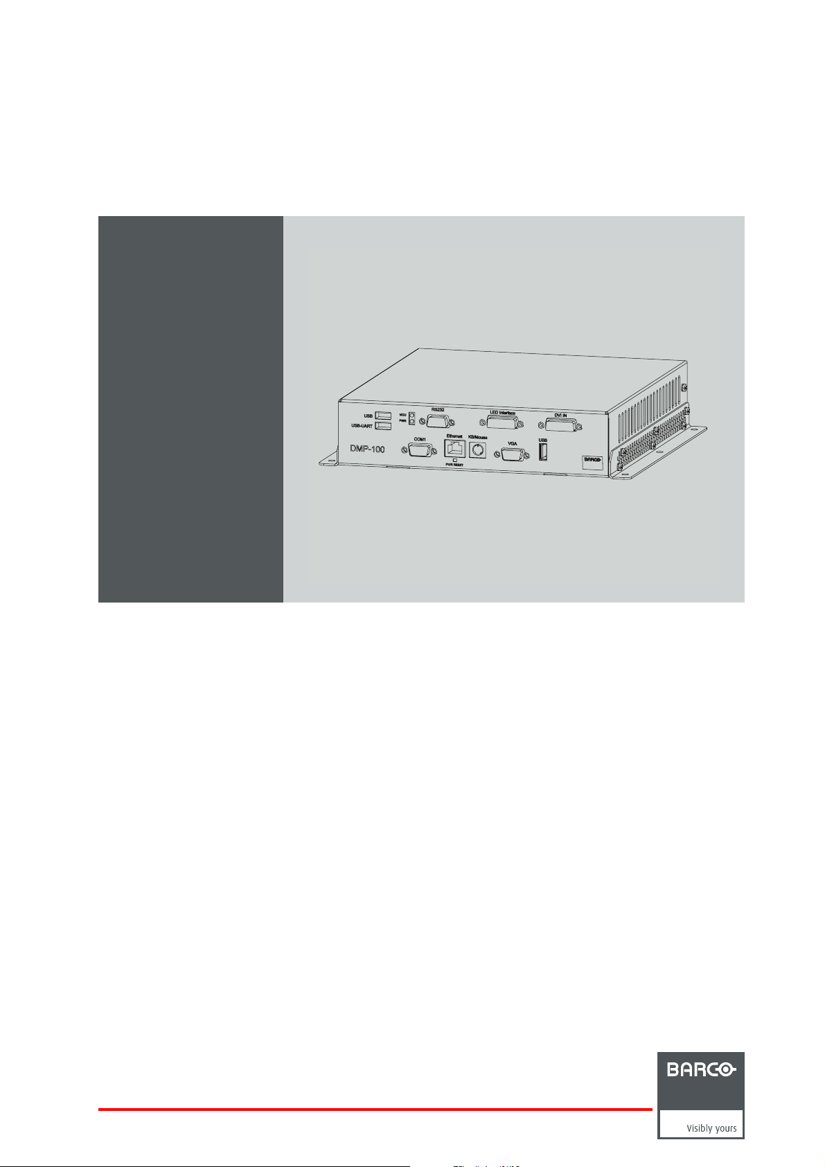
DMP-100
Installation Guidelines
R59770263/06
15/09/2011
Page 2

Barco nv Media & Entertainment Division
Noordlaan 5, B-8520 Kuurne
Phone: +32 56.36.82.11
Fax: +32 56.36.883.86
Support: www.barco.com/esupport
Visit us at the web: www.barco.com
Printed in China
Page 3

Changes
Barco provides this manual ’as is’ without warranty of any kind, either expressed or implied, including but not limited to the implied warranties or merchantability and fitness for a particular purpose. Barco may make improvements and/or changes to the product(s) and/or the
program(s) described in this publication at any time without notice.
This publication could contain technical inaccuracies or typographical errors. Changes are periodically m ade to the information in this
publication; these changes are incorporated in new editions of this publication.
The latest edition of Barco manuals can be dow nloaded from the Barco web site w
h
ttps://my.barco.com.
ww.barco.com or from the secured Barco web site
Guarantee and Compensation
Barco provides a guarantee relating to p erfect manufacturing as part of the legally stipulated terms of guarantee. On receipt, the purchaser
must immediately inspect all delivered goods for damage incurred during transport, as well as for material and manufacturing faults Barco
must be informed immediately in writing of any complaints.
The period of guarantee begins on the date of transfer of risks, in the case of special systems and software on the date of c omm issioning,
at latest 30 days after the transfer of risks. In the event of justified notice of complaint, Barco can repair the fault or provide a replacement
at its own discretion within an appropriate period. If this measure proves to be impossible or unsuccessful, the purchaser can demand a
reduction in the purchase price or cancellation of the contract. All other claims, in particular those relating to compensation for direct or
indirect damage, and also damage attributed to the operation of software as well as to other services provided by Barco, being a component
of the system or independent service, will be deemed invalid provided the damage is not proven to be attributed to the absence of properties
guaranteed in writing or due to the intent or gross negligence or part of Barco.
If the purchaser or a third party carries out modifications or repairs on goods delivered by Barco, or if the goods are handled incorrectly,
in particular if the systems a re commissioned operated incorrectly or if, after the transfer of risks, the goods are subject to influences not
agreed upon in the contract, all guarantee claims of the purchaser will be rendered invalid. Not included in the guarantee coverage are
system failures which are attributed to programs or special electronic circuitry provided by the purchaser, e.g. interfaces. Normal wear as
well as normal maintenance are not subject to the guara ntee provided by Barco either.
The environmental conditions as well as the servicing and m
the customer.
aintenance regulations specified in the this manual must be complied with by
Copyright ©
All rights reserved. No part of this document m ay be copied, re produced or translated. It shall not otherwise be recorded, transmitted or
stored in a retrieval system without the prior written consent of Barco.
Trademarks
Brand and product names m entioned in this manual may be trademarks, registered trademarks or copyrights of their respective holders.
All brand and product names mentioned in this manual serve as commen ts or examples and are not to be understood as advertising for
the products or their manufacturers.
Federal Communications Commission (FCC Statement)
This equipment has been tested and found to comply with the limits for a class A digital device, pursuant to Part 15 of the FCC rules.
These limits a re designed to provide reasonable protection against harmful interference when the equipment is operated in a commercial
environment. This equipment generates, uses, and can radiate radio f requency energy and, if not installed and used in accordance with
the instruction manual, may cause harmful interference to radio communications. Operation of this equipment in a residential area may
cause harmful interference, in which case the user will be responsible for correcting any interference at his own expense
EN55022/CISPR22 Class A ITE (Information Technology Equipment)
Class A ITE is a category of all other ITE which satisfies the class A ITE limits but not the class B IT E limits. Such equipment sho uld not
be restricted in its sale but the following warning shall be included in the instructions for use:
Warning : This is a class A product. In a domestic environment this product may cause radio interference in which case the user may be
required to take adequate measures.
Page 4

Page 5

Table of contents
TABLE OF CONTENTS
1. Safety................................................................................................................ 3
1.1 Important Safety Instructions ........................................................................................................ 3
1.2 Important Warnings. ................................................................................................................. 3
2. Introduction . ................ ................ ................ ................ ................ .................. ..... 5
2.1 General functionality................................................................................................................. 5
2.2 Order info DMP-100 processor ..................................................................................................... 6
2.3 Content ofa DMP-100 package .................................................................................................... 6
2.4 Technicalsummary.................................................................................................................. 7
2.5 Dimensionsof the DMP-100 processor............................................................................................. 8
2.6 Components of the DMP-100 processor. .. . ........................................................................................ 8
3. Physical installation of the DMP-100 processor .......... ................ ................ ................ ...11
3.1 Installation requirements . . ..........................................................................................................11
3.2 Connections of the DMP-100 processor . .. . ........................................................................................12
4. Cables for the DMP-100 processor.............................................................................15
4.1 Cables ...............................................................................................................................15
5. Embedded PC............... ................ .................. ................ ................ ................ .....17
5.1 Configuration ........................................................................................................................17
5.2 Embedded PC operating system, settings. . ........................................................................................18
5.3 Specifications of the em bedded PC ................................................................................................20
6. Configuration scheme ............... .................. ................ ................ ................ ...........23
6.1 Overview .............................................................................................................................23
7. Control software...................................................................................................27
7.1 RMS.................................................................................................................................. 27
7.2 Flashloader . .........................................................................................................................27
7.3 Downloading Flash loader . ..........................................................................................................27
7.4 Using Flash loader. ..................................................................................................................27
8. Maintenance....... ................ ................ ................ ................ ................ ................ .29
8.1 Cleaning the cabinet................................................................................................................. 29
9. Environmental information ......................................................................................31
9.1 Disposal information.................................................................................................................31
R59770263 DMP-100 15/09/2011
1
Page 6

Table of contents
2 R59770263 DMP-100 15/09/2011
Page 7
1. SAFETY
1.1 Important Safety Instructions
Instructions:
• Read these instructions.
• Keep these instructions.
• Heed all warnings.
• Follow all instructions.
• Do NOT submerge fully or partly in water or other liquids.
• Clean only with materials or chemicals that are inert, nonabrasive, noncorrosive and non-marking. Consult the manufacturer
for further advice should any doubts exist regarding any cleaning procedure.
• Do not block ventilation openings. Install in accordance with the manufacturers instructions.
• Do not install near any heat sources such as radiators, heat registers, stoves, or other app aratus (including amplifiers) that
produce heat.
• Do not defeat the safety purpose of the polarized or grounding type plugs/sockets. If the provided sockets / plugs are damaged
then replacement of the defective parts m ust be undertaken immediately.
• Protect the power/data cords from being walked on or pinched particularly at plugs, convenience receptacles, and the point
where they exit from the apparatus. Replace damaged power/data cords im mediately.
• Only use attachments/accessories specified by the manufacturer.
• Disconnect the power to this apparatus during lightning storms or provide suitabl
apparatus when unused for long period of time.
• Refer all servicing to qualified service technicians/personnel. Servicing is required when the apparatus has been damaged in
any way, such as power-supply cord or plug is damaged, the appa ratus does not opera te normally, or has been dropped.
• Use only with systems or peripherals specified by the manufacturer, or sold with the apparatus. Use caution during lifting/moving
or transporting to avoid damage by possible tipping.
e additional lightning p rotection. Unplug this
1. Safety
1.2 Important Warnings
Important Warnings:
• Risk of electric shock:
Image 1-1
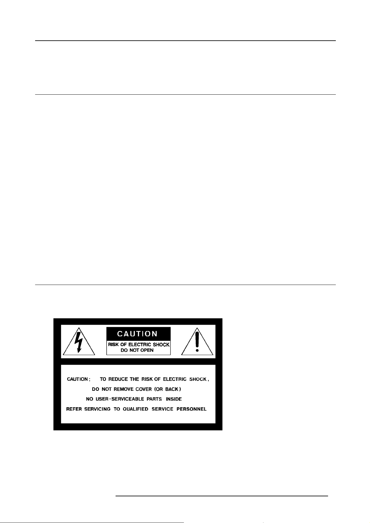
Risk of electric shock. Do not open. To reduce the risk of electric sho ck, do not remove cover (or back). No user-serviceable
parts inside. Refer servicing to qualified service personnel.
The lightning flash with an arrowhead within a triangle is intended to tell the user that parts inside this product m ay cause a risk
of electrical shock to persons.
The exclamation point within a triangle is intended to tell the user that important operating and/or servicing instructions are
included in the technical documentation for this equipment.
R59770263 DMP-100 15/09/2011
3
Page 8

1. Safety
• Maximum ambient temperature:
The maximum recommended ambient temperature for this equipment is 50°C.
• Flammable materials:
Keep flammable materials away from the installation (such as curtains). A lot of energy is transferred into heat. The installation
should be such that the amount of air flow required for safe operation of the equipment is not compromised. Proper ventilation
must be provided.
• This equipment MUST be earthed:
In order to protect against risk of electric shock, the installation should be properly grounded. Defeating the purpose of the
grounding type plug will expose you to the risk of electric shock. This apparatus must be grounded (earthed) via the supplied
3 conductor AC power cord. (If the supplied power cord is not the correct variant, consult your dealer.)
• Power system:
It is recommended to use a TN-S power distribution system (a power distribution system with a separate neutral a
conductor) in order to avoid large ground currents loops due to v oltage differences in the neutral conductor. T he total electrical
installation should be protected by an appr opriate rated disconnect switch, circuit breakers and Ground Fault Current Interrupters. The installation shall be done according to the local e lectrical installation codes. In Europ
given to EN 60364, the standard for electrical installation of buildings. In G ermany VDE 0100 should be adhered to.
• Mains cords:
The power cords delivered with this system have special properties for safety. T hey are not user serviceable. If the power cords
are damaged, replace only w ith new ones. Never try to repair a power cord.
• Use of an extension cord:
If an extension cord is us ed with this product, make s ure that the total of the ampere ratings on the products plugged into the
extension cord does not exceed the extension c ord ampere rating. Also make sure that the total of all products plugged into
the wall outlet does not exceed 15 amperes.
• Cabinet openings:
Never push objects of any kind into this product through cabinet slots as they may touch dangerous high voltage points or short
out parts that could result in a risk of fire or electrical shock.
Never spill liquid of any kind on the product. Should any liquid or solid object fall into the cabinet, unplug the set and have it
checked by qualified service personnel before resuming operations.
nd grounding
e special attention should be
4
R59770263 DMP-100 15/09/2011
Page 9
2. Introduction
2. INTRODUCTION
Overview
• General functionality
• Order info DMP-100 processor
• Content of a DMP-100 package
• Technical s umm ary
• Dimensions of the DMP-100 processor
• Components of the DMP-100 pr ocessor
2.1 General functionality
Overview
The DMP-100 is a video processing dev ice, designed to drive exclusively Barco LED wa lls. The DMP-100 is a powerful DVI signal
processor that accepts a wide range of DVI input modes and processes them to drive Barco LED w a lls. T he D MP -100 supports DVI
output as the output format.
By using RMS-1 control software, the DMP-100 allows you to control and monitor a display using the digital output. RMS -1 will give
you full control ov er everything from basic setup to configuration, advance
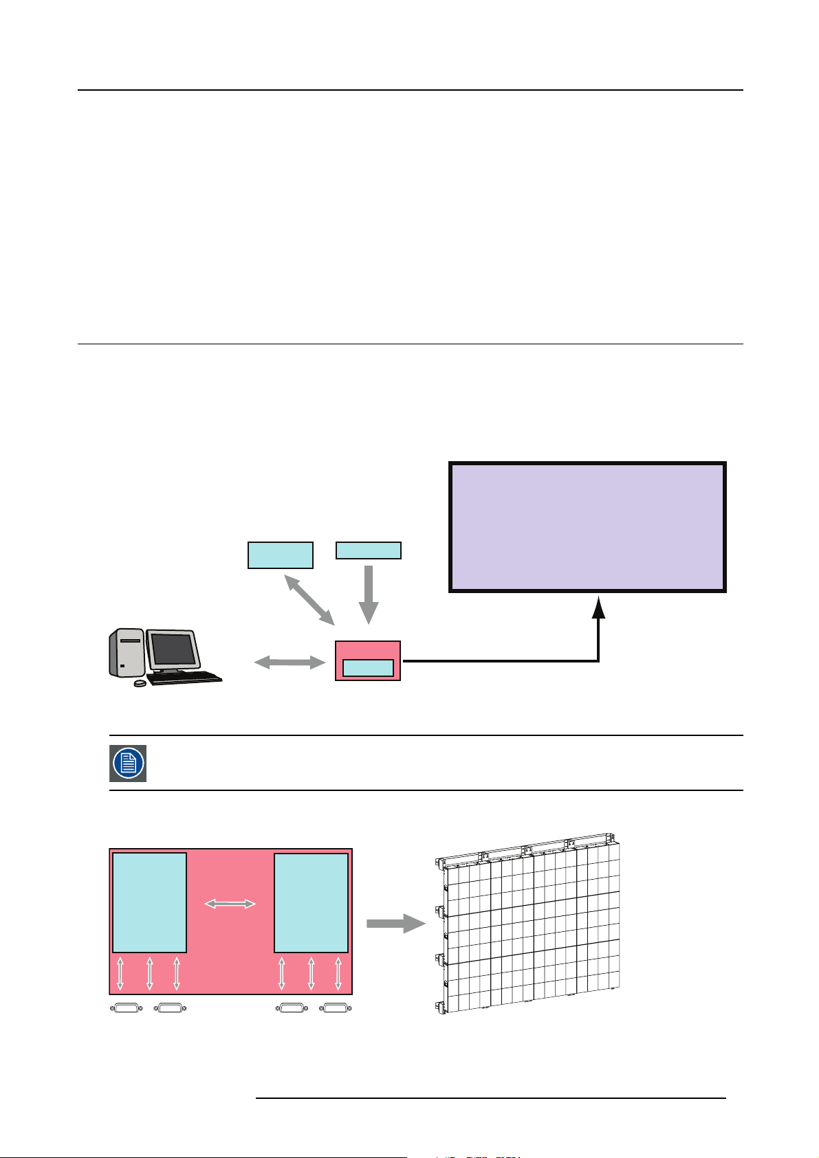
Display
d feature control and (automated) remote diagnostics.
**
Remote control
through TCP/IP
SOURCE 1
**
Optional
Control PC
Image 2-1
* Default connection.
** Optional connection for maintenance reasons.
SOURCE 2 is used as a back-up source in case one of the default connections does not exist.
Configuration of the DMP-100 processor
DMP-100
Embedded PC
Digitizer Board
DMP-100
SOURCE 2
DVI input
Formated Video Data
Image 2-2
The DMP-100 c an be split up i
acts as a scaler for the provided input. Each part has its own interface connections and both parts are internally linked together.
R59770263 DMP-100 15/09/2011
nto two main parts: one part b eing the embedded PC, the other part being the processor itself which
5
Page 10
2. Introduction
2.2 Order info DMP-100 processor
Order info:
Article number Description
R9828833 DMP-100 processor
2.3 Content of a DMP-100 package
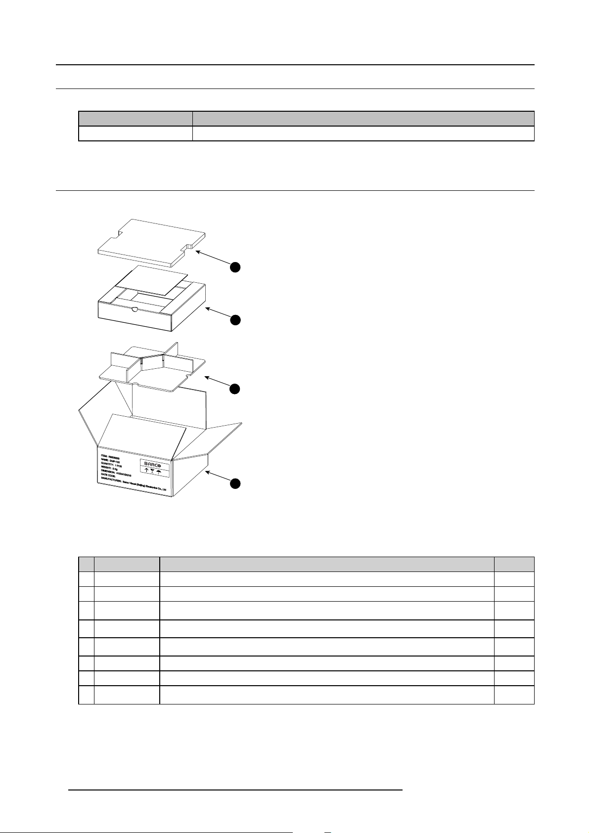
Package
2
1
3
4
Image 2-3
1 Protective cover for the DMP-100 processor and installation manual.
2 Cover.
3 Container for all cables and accessories.
4 DMP-100 total package.
What’s inside of packaging
No. A rticle number Description
1 R9828833 DMP-100 1
2 R59770263 Manual 1
3 R9851211
4 R9851210
5
Z3499916 Data cable with SUBD connectors for RS232 connection between local control PC and CO M 1
6 R326103
7
R3261115
8 Z3499213
0.9 meter data cable with D VI connectors. Used to connect a display PC with the DMP-100
processor.
5 m eter data cable with DVI connectors. Used to connect the LED-WALL OU TP UT with
a Barco D B-x 20 billboa
RS232 input port of the DMP-100 processor.
Power cable with CEE7 plug. (used in Europe).
PowercablewithNEMA5—15plug. (usedinUSA).
Used to connect a LED-WALL and a B arco display. (T-16/TF-16/SP-20/S14/T20/TF20/SLITE/S10XP)
rd.
Quantity
1
1
1
1
1
1
About the cable’s image please see the division"Cables", page 15
6
R59770263 DMP-100 15/09/2011
Page 11
2.4 Technical summary
Summary
Typ e Valu e
Input
Compatibility Barco DVI based LED walls, S10XP FX or newer (Barco NNI tiles are not supported)
Output DVI-A, Barco LED protocol. (supported resolutions 800x600@60HZ / 1024x768@50HZ )
Scaler Default set to cropping but scaling is possible.
Z-order control Not available.
Window po sitioning
Connectors RS 232 [RJ 11] — Ethernet [RJ 45].
Memory
Effects Contrast, brightness and sharpness adjustment.
Ruggedness IP10
Dimensions
Weight
Operating temperatures 0 ºC <> 50 ºC
Power consumption 50 W.
Stacking
Chaining
Control software RMS-1 (provided by Barco). Note: DMP-100 is not supported by Director Toolset
DVI input (supported resolutions 800x600 / 1024x768 / 1600x1200)
Intuitive positioning interface.
1GB RAM.
4GB internal CF card.
Without screw pillar: 230 x 262.4 x 56 (W x D x H)
With screw pillar: 247.4 x 262.4 x 56 (W x D x H)
±2.8 K g (without package)
No stacking possible.
No chaining possible.
2. Introduction
R59770263 DMP-100 15/09/2011 7
Page 12
2. Introduction
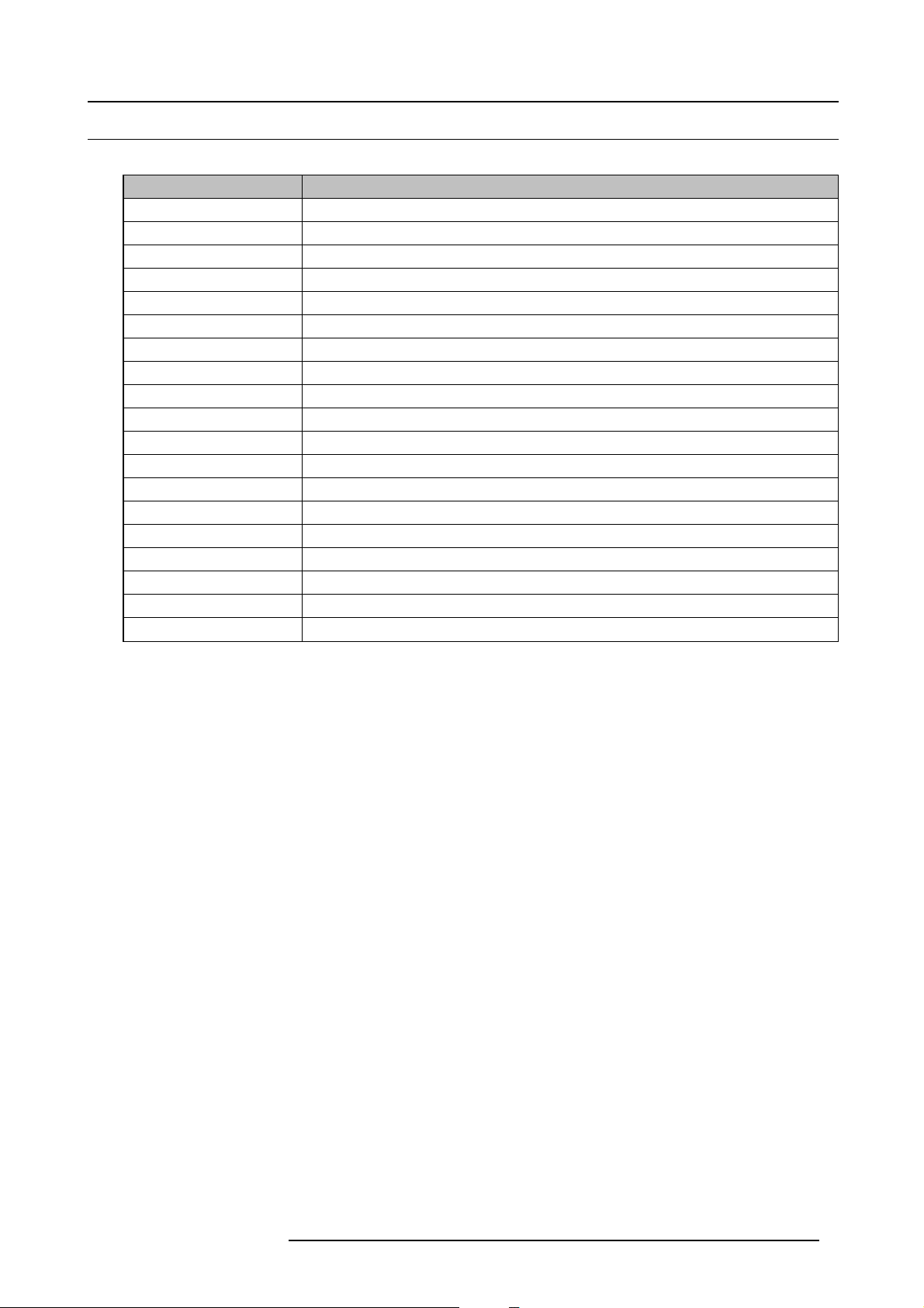
2.5 Dimensions of the DMP-100 processor
Dimensions of the DMP-100 processor
262.4 mm
250 mm
110 mm
110 mm
266 mm
250 mm
56 mm
1.5 mm
Image 2-4
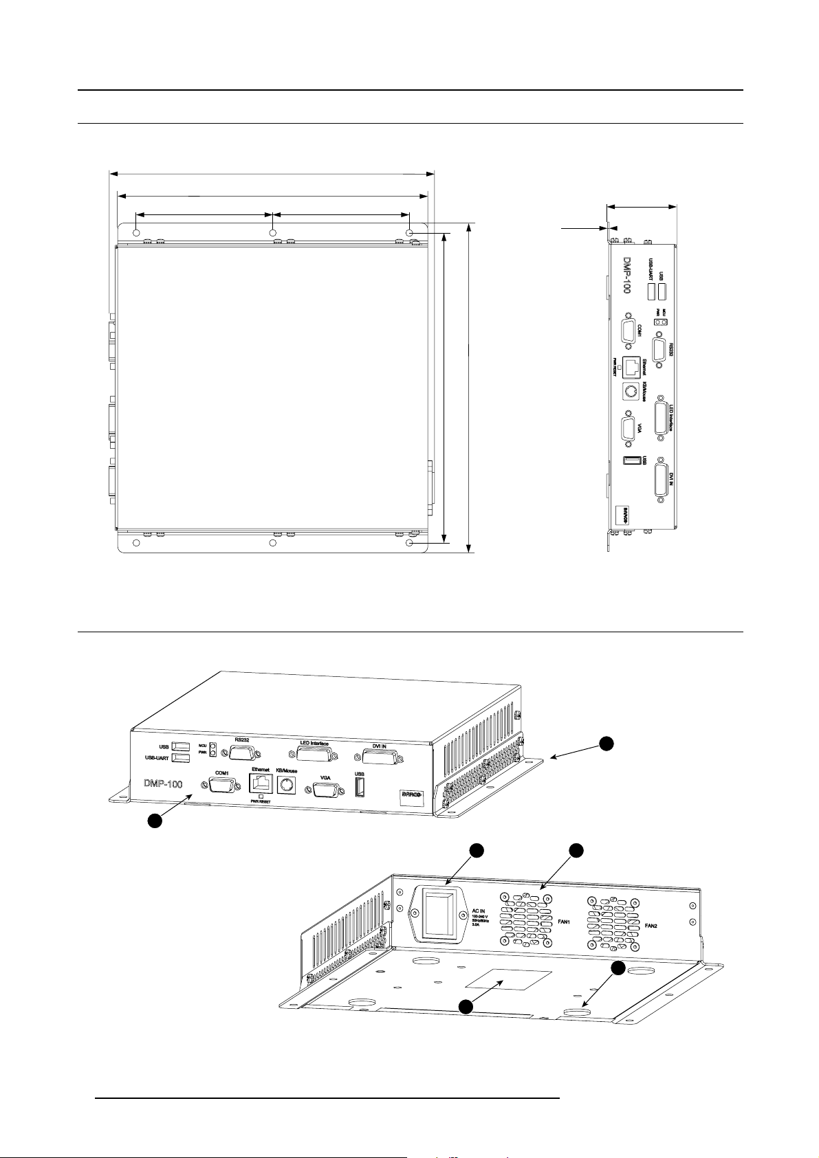
2.6 Components of the DMP-100 processor
Component overview
1
2
3 4
5
6
Image 2-5
1 Front side of the DMP-100 processor, including all connection interfaces, see "Connections of the DMP-100 processor", page 12
2 Positioning rail.
3 AC power connector with integrated switch.
8 R59770263 DMP-100 15/09/2011
Page 13

4 Cooling fans.
5 Soft supports.
6ETLcertification label.
2. Introduction
R59770263 DMP-100 15/09/2011 9
Page 14

2. Introduction
10 R59770263 DMP-100 15/09/2011
Page 15

3. Physical installation of the DMP-100 processor
3. PHYSICAL INSTALLATION OF THE DMP-100
PROCESSOR
Overview
• Installation requirements
• Connections of the DMP -100 processor
3.1 Installation requirements
Requirements
• The DMP-100 processor should not be placed in a built-in installation or enclosure unless p roper ventilation is provided.
• When using the unit in a multi unit rack assembly or closed assembly, the ambient temperature inside the assembly may not
exceed the rated ambient temperature (0 -50°C) of the processor. The installation should be such that the amount of air flow
required for safe operation of the equipment is not compromised.
• When building in the DM P- 100 processor into a rack with cov er door, be aw are that a space of minim um 85 mm is needed
between the indicated reference and the cover door. T his space is needed to guide the input cables to the inputs.
Image 3-1
The front side of the DMP-100 processor is considered as reference for this installation requirement.
• The DMP-100 processor will require that air flows freely in vent holes. Blocking these holes will greatly reduce the reliability of
the unit and lead to the possibility of overheating.
• The DMP-100 proc essor s hould operate from an A C
power supply from 100 to 240 volt ( 50–60 Hertz).
• When installed in a rack, the m ounting should be such that no hazardous condition is achieved due to uneven mechanical
loading.
• When the mains switch located on the back of the DMP-100 processor is not accessible due to rack mounting, the socket outlet
supplying the rack shall be installed near the equipment and be easily accessible or a readily accessible disconnect device shall
be incorporated in the fixed wiring. When using a rack in an installation it is advisable to log the serial number of the device and
to activate the warranty figure by registering utilizing the included form.
• Do not place the DMP-100 processor on an u nstable cart, stand or table. The device may fall, causing personal injury and
serious damage to the processor.
• The data path between the DM P-1 00 processor and the LED display may not exceed ten (10) meter.
power source. The DMP -100 processor is equipped with an auto-ranging
R59770263 DMP-100 15/09/2011
11
Page 16

3. Physical installation of the DMP-100 processor
3.2 Connections of the DMP-100 processor
Front panel connections
1 2 3 4 5 6
7 8 9 10 11
Image 3-2
Nr.
Connector
1
USB interface Common U SB interface for the embedded PC.
2
USB — UART interface USB interface for external control PC which can be used to update software or firmware.
3 Indicator light PWR: indicates power supply.
4
RS-232 Used by RMS software on an external control PC to communicate with the DMP-100
5
LED interface DVI Output to LED wall (Barco proprietary protocol).
6 DVI input External DVI source signal input port.
7
COM 1 Embedded PC COM 1 port .
8 Ethernet interface Embedded PC Ethernet interface for remote con trol.
9 Mouse interface Embedded PC m ouse / Keyboard port.
10 VGA interface Embedded PC VGA display po rt.
11 USB interface Embedded PC USB port.
Description
MCU: indicates the MCU work status.
processor.
WARNING: Connectors number 1, 2 and 11 are all USB interfaces b ut there is a significant difference between
them.
Connector 1 and 11 are connected with the embedded P C board and are therefor embedded PC USB interfaces.
Connector 2 is connected with the embedded digitizer board and is used to update software and firmware.
WARNING: Connectors number 4 and 7 are both RS—232 interfaces but there is a signifi cant difference be-
tween them.
Connector 7 is connected with the em bedded PC b oard and is therefor an embedded PC COM 1 port.
Connector 4 is connected with the processor board and is used by the e xternal control PC to communicate
with the DMP-100 p rocessor.
12 R59770263 DMP-100 15/09/2011
Page 17

Image 3-3
14-9000094-90
3. Physical installation of the DMP-100 processor
WARNING: The power connection is located on the back side of the DMP-100 processor and includes an
integrated interruption switch.
R59770263 DMP-100 15/09/2011 13
Page 18

3. Physical installation of the DMP-100 processor
14 R59770263 DMP-100 15/09/2011
Page 19

4. Cables for the DMP-100 processor
4. CABLES FOR THE DMP-100 PROCESSOR
4.1 Cables
List with available cables
Article number Description Image
Z3499213
R326103
R3 2 6 1115
R9851211
R9851210 Five meter data cable w ith DVI connectors. Used to connect the LED-WALL
Z3499916 Data cable with SUBD connectors for RS232 connection between local
Used to connect a LED-WALL and a Barco display. (T-16/TF-16/SP20/S14/T20/TF-20/SLITE/S10XP)
Power cable with CEE7 plug. (used in Europe).
PowercablewithNEMA5—15plug. (usedinUSA).
0.9 meter data cable with DVI connectors. Used to connect a display PC
with the DMP-100 processor.
OUTPUT with a Barco DB-x20 billboard.
control PC and COM1 RS232 input port of the DMP-100 processor.
Image 4–1
Image 4–2
Image 4–3
Image 4–4
Image 4–5
Image 4–6
Image 4-1
Z3499213
Image 4-4
R9851211
Image 4-2
R326103
Image 4-5
R9851210
Image 4-3
R3261115
Image 4-6
Z3499916
R59770263 DMP-100 15/09/2011 15
Page 20

4. Cables for the DMP-100 processor
16 R59770263 DMP-100 15/09/2011
Page 21

5. Embedded PC
5. EMBEDDED PC
Overview
•Configuration
• Embedded PC operating system, settings
•Specifications of the embedded PC
5.1 Configuration
Configuration of the embedded PC
The embedded PC is a powerful built-in PC which is used as control PC. This offers the DMP-100 processor its benefit compared
to other digitizers, the use of an external control PC is no longer needed. To operate the embedde d PC, connections 1 and 3 can
be used.
INTERNAL PC
1
Play PC
Keyboard and mouse
CRT or LCD
Embedded PC
Video 2
RS 232-1
USB-UART
a
b
Video 1
Digitizer Board
c
DMP-100
2
3
Image 5-1
1 Connection 1: Connecting a CRT/LCD display, keyboard and mouse.
2 Connection 2: Connecting a laptop.
3 Connection 3: Remote control.
a Port used to run the LE D toolset or
b USB — UART transmitter. (used during maintenance)
c RS 232 transceiver. (used duri
Connection 1: Manipulating t
By plugging in a CRT or LCD display, a ke yboard and a mouse the embedded PC can be manipulated directly.
RS 232
USB-UART
RS 232
TCP/IP
RMS-1. (used when operating)
ng maintenance)
he embedded PC directly
When changing to this configuration, make sure that the control software of the configurations d escribed
below is switched off. Consult the manual of the control software for more information.
Connection 3: Off-site manipulation (remote control), used as default
By connecting through the TCP/IP (Ethernet) port, the embedded PC can be manipulated through remote control.
R59770263 DMP-100 15/09/2011
17
Page 22

5. Embedded PC
WARNING: T he Play PC is always used as default. If the Play PC does not exist or has been damaged, the
DMP-100 processor will automatically use the embedded PC as a back up solution. If the play PC has been
damaged, a notification will be given by the used control software.
If the Play PC is not used, data can be provided to the emb edd ed PC by using the 4GB CF card installed inside
the DMP-100 processor. Content can be put on the CF card by connecting a USB device to the DMP-100 or b y
connecting by remote control (TCP/IP connection).
5.2 Embedded PC operating system, settings
What should be done ?
During installation there are several settings which must be verified and set in the embedded PC operating system. Failure to set
some of these c an lead to loss of data or incorrect calculations of time based functions.
Set the display resolution
1. R ight click on the de sktop to open the context menu.
Image 5-2
2. S elect P roperties.
The P roperties window opens.
3. Click o n Settings tab.
4. A djust the resolution of the primary di
Note: By default, the secondary display is set to 1024x768 and should normally not be adjusted. There are restrictions of
supported resolutions of the secondary adapter since it is used as a backup input for the DMP-100.
5. Click OK.
Configure the time zone, date, and time
1. Double c lick the time in the system tray.
18
splay.
R59770263 DMP-100 15/09/2011
Page 23

5. Embedded PC
Or,
click Start → Control panel.FromtheClassic View of that panel, double click on Date and Time.
Image 5-3
2. Click o n Time Zone tab.
3. Click on the drop down list to select the time z one that corresponds to the time zone where the DMP-100 is being installed.
4. Click o n Date & Time tab.
5. In the Date section choose the correct day, month, and year.
6. In the Time section set the time corresponding to the correct time of the time zone using the up down buttons next to the current
time.
7. Click OK.
Disable the write cache of the disk
1. O pen My Computer from the desktop
Or,
click on Start → My computer.
2. Right click on the C drive and s elect Properties (1).
R59770263 DMP-100 15/09/2011
19
Page 24

5. Embedded PC
Image 5-4
3. Click on the H ard w are tab (2).
4. Make sure the disk drive corresponding to the C: drive is selected in the All disk drives section (3).
5. Click P roperties (4).
6. Click on the Po licies tab (6).
7. U ncheck the Enable write caching on the disk box (7).
8. Click OK, then click OK once more to close the drive properties dialog.
9. If prom pted, reboot the PC
5.3 Specifications of th e embedded PC
Standard 3.5" biscuit SBC functions
Typ e Valu e
CPU Embedded Intel Atom N2 70 1.6 GHz Processor
System m emory D DR2 Memor y support up to 2GB
2nd cache memory 512 KB.
System ch ipset Intel 945GSE
BIOS
Watchdog timer Programm able 1 ~ 255sec
Expansion interface PCI-104.
Memory
Battery
Power managem ent
AWARD 4Mbit
1GB RAM / 4GB internal CF card
Lithium 3V/210mAH
APM1.2, ACPI3.0, wake on LAN , and modem ring-in functions
20 R59770263 DMP-100 15/09/2011
Page 25

Enhanced IDE interface ICH7M support
Single, independent IDE signal channel
Serial ports Two serial RS-232 ports,
Parallel port 26-pin fl at-cable connector
Keyboard / mouse connector PS/2 Keyboard and Mouse interface
Audio
USB USB 2.0 compliant P orts
Solid state disk (SSD) Supports Com pact Flash Card Type Ⅰ/Ⅱ
GPIO 8-bit general purpose input/output
SMBus System Management Bus for advanced monitoring / control interface.
Supports one CF device
COM1(RS-232), DB-9 C OM2(R S-232/422/485)
Connector: Mini-Din 6P at coastline
High Definition Audio(HD)
VGA / LVDS interface
Typ e Valu e
Chipset Intel 945GSE
Memory Size Up to 64MB of dynamic video memory allocation
Resolution
TTL LCD Supports 18-bit TTL LCD
LVDS LCD Supports 36-bit LVDS LCD
Dual independent display
CRT display Mode: Supports QXGA up to 2048x1536
TTL display Mod e: Up to 800x 600
CRT+LVDS (36-bits)
CRT+TTL (18-bits)
5. Embedded PC
Ethernet interface
Typ e Valu e
Chipset supports Realtek 8110SC
Speed
Interface
Standard Compliant with IEEE 802.3, IEEE 802.3u, IEEE 802.3x, IEEE 802.ab
1000 Mbips
1xRJ45 connector.
Mechanical and environmental specifications
Typ e Valu e
Dimensions 145 x 102 mm (5.9" x 4.2").
Power supply type AT/ATX
Power requirements ATX: +5V±5 %, ±12V±5 %
Power consumption
Operating temperature 0 ~ 50°C (32 ~ 122°F).
Operating humidity 0% ~ 90% relative humidity, non-condensing.
Weight 0.85 kg.
AT: 5V only to boot up (12V is optional for LCD inverter and add on card)
Typical (WinXP Idle Mode): +5V@1.9A, +12V@0.07A
Max (Test in HCT):+5V@2.38A, +12V@0.09A
R59770263 DMP-100 15/09/2011 21
Page 26

5. Embedded PC
22 R59770263 DMP-100 15/09/2011
Page 27

6. CONFIGURATION SCHEME
6.1 Overview
Scheme
Display
6. Configuration scheme
**
Remote control
through TCP/IP
SOURCE 1
DVI input
**
Optional
Control PC
Image 6-1
*Thefiberlink is optional.
** Default connection.
*** Optional connection for maintenance reasons.
A DMP -100 is sufficient to drive one Barco LED wall.
DMP-100
SOURCE 2
3 different configurations;
1. Default through remote control (TCP/IP).
2. By connecting an external laptop, keyboard and mouse.
3. By plugging in a display, keyboard and mouse.
How to set up the remote control configuration?
1. M ake sure the power of the D MP -100 is turned off.
2. Connect the internet cable to the Ethernet port and a data cable to connect the DMP-100 processor with the LED-wall trough the
LED interface port.
Formated Video Data
Image 6-2
R59770263 DMP-100 15/09/2011 23
Page 28

6. Configuration scheme
Image 6-3
3. Turn on the power of the DMP-100.
Note: The Led’s indicated with “PWR” and “MCU” will light up.
4. Use the REAL VNC application on the remote PC to login to the embedded PC .
5. U se the RMS control software to com municate with the DMP-100 processor.
WARNING: The DMP-100 processor does not support the “HOT SWAP” function. The LED-wall and the DMP-
100 should be sw itched off b efore any cable can be d isconnected or reconnected.
Use the Flash Loader software to download updates on the software and firmware used by the DMP-100 processor.
How to connect a laptop to locally control the DMP-100 processor?
1. Turn on the power of the DMP-100.
Note: The Led’s indicated with “PWR” and “MCU” will light up.
2. Wait until the operating system and the RMS software has loaded.
3. S hut down the operating software.
4. Wait until the operating system has fully shut down.
5. C onnect the DVI cable ( R 9851210) between the DMP-100 processor and the LED-wall, using the LED Interface port.
Image 6-4
6. Connect a serial line (Z3499916) from the control PC to the RS232 interface.
Image 6-5
7. U se the connected laptop to communicate with the DMP-100 processor.
24
R59770263 DMP-100 15/09/2011
Page 29

6. Configuration scheme
If a display or billboard is up and running, the user can start from step 3.
Connect the control PC w ith the DMP-100 processor, using a USB line on the USB-UART port, to update the
software and firmware us ed by the DMP-100 processor through the embedded Flash Loader software.
How to manipulate the embedded PC by connecting a display, keyboard and mouse?
1. Turn off the power of the DMP-100.
2. Disconnect the RS232 cable if one is connected to the RS232 interface.
3. C onnect the DVI cable ( R 9851210) between the DMP-100 processor and the LED-wall, using the LED Interface port.
Image 6-6
4. C onnect a CRT or LCD display to the DMP-100 processor through the VGA port.
Image 6-7
5. C onnect a keyboard and a mouse, using the KB/Mouse port or USB port.
Image 6-8
6. Turn on the CRT or LCD display.
7. Turn on the power of the DMP-100 and restart the operating system.
Note: The Led’s indicated with “PWR” and “MCU” will light up.
8. Wait until the operating system and RM S software are up and running.
9. O perate the DMP-100 by using the connected peripherals.
WARNING: Before turning off the DM P-100 processor, please first shut down all windows operation systems
and the embedded PC.
R59770263 DMP-100 15/09/2011 25
Page 30

6. Configuration scheme
Alternatively, step 2 and 3 can be carried out together b y pushing the reset button.
Use the Flash Loader software to download updates on the software and firmware used by the DMP-100 processor.
26 R59770263 DMP-100 15/09/2011
Page 31

7. CONTROL SOFTWARE
7.1 RMS
General introduction
RMS control s oftware is running on the embedded P C inside DMP- 100 to configure and control the DMP-10
wall from bas ic set-up to advanced features such as input timing, brightness control setup and monitoring tools.
7. Control software
0 and associated LED
Image 7-1
CAUTION: Refer to the manual of the RMS software (R59770142) for more information about installation and
usage guidelines.
7.2 Flashloader
General introduction
Flash loader is a stand alone program to update the software / firmware of the DMP-100 processor. The flash loader software can
run from an embedded PC or an external control PC. The embedded PC already has this software pre-installed.
Flash loader runs on a Windows platform.
7.3 Downloading Flash loader
How to download Flash loader?
These Flash loader software can be downloaded from the secured Barco web site https://my.Barco.com. Fill in the description in
the search engine to find and download the correct files.
7.4 Using Flash loader
How to use Flash loader
1. S etup Flash loader.
2. Run Flash loader.
R59770263 DMP-100 15/09/2011
27
Page 32

7. Control software
Image 7-2
3. Click Commu nication > RS232 Config > Baud, and select 38400.
4. Click Communication > RS232 Config > COM Port, and select the COM port on the PC to which the DMP-100 is connected.
If no other programs are us ing the port, the “Established communications” m essage appears at the bottom of the Flash Loader.
Note: If no other pr ograms are using the port, the “Established comm unications” message appears at the bottom of the Flash
Loader.
5. To upload files to the DMP-100, click “Open script file to read and u
6. In the dialog, select "Upload_All.sl d" and click Open. The DMP-100 unit should imm ediately display the "System in LOADER
MODE" message.
7. It takes s everal minutes to load the flash memory. When complete, the Flash Loader utility displays the “Upload Complete”
message. Click OK to continue.
8. C ycle power on the DMP-100.
9. E xit the Flash Loader utility.
pload”.
28
R59770263 DMP-100 15/09/2011
Page 33

8. Maintenance
8. MAINTENANCE
8.1 Cleaning the cabinet
CAUTION: Do not use liquid cleaners or aerosol cleaners. Never use strong solvents, such as thinner or
benzine, or abrasive cleaners, since these will damage the cabinet.
Necessary tools
Damp cloth.
How to clean the cabinet
1. Unplug the DMP-100 processor from the wall outlet before cleaning.
2. Clean the cabinet with a damp cloth. S tubborn stains may be removed with a cloth lightly dampened with mild detergent solution.
To keep the cabinet looking brand-new, periodically clean it with a soft dry cloth.
R59770263 DMP-100 15/09/2011 29
Page 34

8. Maintenance
30 R59770263 DMP-100 15/09/2011
Page 35

9. Environmental information
9. ENVIRONMENTAL INFORMATION
9.1 Disposal information
Disposal Information
This equipment has required the extraction and use of natural resources for its production. It may c
health and environment. In or der to avoid the dissemination of those substances in the environment and to diminish the p ressure
on natural resources, we encourage you to use the appropriate take-back systems. Those systems w ill reuse or recycle most of the
materials of your end of life equipment in a sound way.
The crossed-out wheeled bin symbol inv ites you to use those systems. If you need more information on the collection, reuse and
recycling systems, please contact your local or regional waste administrator. You can also contact us for m ore information on the
environmental performances of our products.
Disposal of batteries in the product
ontain hazardous substances for
The crossed-out wheeled bin symbol indicates that batteries and accumulators must be collected and disposed of separately
from household waste.
If the battery or ac cum ulator contains more than the specified values of lead (Pb), mercury (Hg) or cadmium (Cd) according to the
Battery Directive 2006/66/EC, these chem ical symbols will appear below the crossed-out wheeled b in symbol.
By participating in separate collection of batteries, you will help to ensure proper disposal and to prevent potential negative effects
on the environment and human health.
R59770263 DMP-100 15/09/2011
31
Page 36

9. Environmental information
32 R59770263 DMP-100 15/09/2011
Page 37

Revision Sheet
To:
Barco n v Media & Entertainment Division/Documentation
Noordlaan 5, B-8520 Kuurne
Phone: +32 56.36.82.11, Fax: +32 56.36.88.24
Support: www.Barco.com/esupport, Web: www.barco.com
From:
Date:
Please correct the following points in this docum entation (R59770263/06):
page wrong
correct
R59770263 DMP-100 15/09/2011
 Loading...