

Page 1

Projector Toolset
Refere nce guid e
For SLM
R59770183/00
15/07/2009
Page 2

Barco nv Media & Entertainment Division
Noordlaan 5, B-8520 Kuurne
Phone: +32 56.36.89.70
Fax: +32 56.36.883.86
E-mail: sales.events@barco.com
Visit us at the web: www.barco.com
PrintedinBelgium
Page 3

Changes
Barco provides this manual ’as is’ without warranty of any kind, either expressed or implied, including but not
limited to the implied warranties or merchantability and fitness for a particular purpose. Barco may make improvements and/or changes to the product(s) and/or the program(s) described in this publication at any time
without notice.
This publication could contain technical inaccuracies or typographical errors. Changes are periodically made
to the information in this publication; these changes are incorporated in new editions of this publication.
Copyright ©
All rights reserved. No part of this document may be copied, reproduced or translated. It shall not otherw
be recorded, transmitted or stored in a retrieval system without the prior written consent of Barco.
ise
Trademarks
Brand and product names mentioned in this manual may be trademarks, registered trademarks or copyrights
of their respective holders. All brand and product names mentioned in this manual serve as comments or
examples and are not to be understood as advertising for the products or their manufacturers.
Page 4

Page 5

Table of contents
TABLE OF CONTENTS
1. Basic concepts .....................................................................................5
1.1 Introduction ..................................................................................................... 5
1.2 About a Configuration ......................................................................................... 5
1.3 About a Snapshot ..............................................................................................5
1.4 About storing Configurations and Snapshots ............................................................... 5
2. Installation ...........................................................................................7
2.1 General requirements ......................................................................................... 7
2.2 Free download of Projector Toolset .......................................................................... 8
2.3 Projector Toolset installation.................................................................................. 8
2.4 Starting up.....................................................................................................10
2.5 Manual installation of a device plug-in......................................................................13
2.6 Uninstall Projector Toolset ...................................................................................15
2.7 About this manual.............................................................................................15
3. Menus ............................................................................................... 17
3.1 General.........................................................................................................17
3.2 Menu and button bar..........................................................................................17
3.3 Main window...................................................................................................18
3.4 Short cut keys .................................................................................................19
3.5 Workspace Explorer ..........................................................................................19
3.6 How to adjust a setting .......................................................................................20
3.7 About Projector Toolset.......................................................................................20
3.8 Snapshot management.......................................................................................24
3.8.1 About snapshots.........................................................................................24
3.8.2 Managing snapshots....................................................................................25
3.8.3 Take a snapshot .........................................................................................26
3.8.4 Apply a snapshot........................................................................................28
3.8.5 Delete a snapshot.......................................................................................29
3.8.6 Add shot cut key to a snapshot ........................................................................30
3.8.7 Remove shot cut key association......................................................................31
4. Preferences ........................................................................................ 33
4.1 Introduction ....................................................................................................33
4.2 Start up the preferences......................................................................................33
4.3 Access level ...................................................................................................34
4.4 Software Appearance.........................................................................................35
4.5 Bug report setup ..............................................................................................38
4.6 Logging.........................................................................................................39
4.7 Workspace selection..........................................................................................40
5. Configurator ....................................................................................... 43
5.1 Introduction ....................................................................................................43
5.2 Configurator window..........................................................................................43
5.3 Create a new configuration ..................................................................................43
5.4 Add projector to a configuration .............................................................................44
5.4.1 Add projector.............................................................................................44
5.4.2 General properties ......................................................................................46
5.4.3 Connection setup........................................................................................46
5.4.3.1 Set up a serial connection ........................................................................47
5.4.3.2 Set up a Ethernet connection.....................................................................49
5.4.4 Decorator setup..........................................................................................53
5.5 Reconnect a projector ........................................................................................55
5.6 Move projector toa group....................................................................................57
5.7 Edit projectorproperties......................................................................................58
5.8 Configuration preview ........................................................................................59
5.9 Configuration properties......................................................................................59
5.10 Configuration properties, new group........................................................................60
R59770183 PROJECTOR TOOLSET 15/07/2009
1
Page 6

Table of contents
5.11 Preview layout properties ....................................................................................61
5.11.1 Background color........................................................................................61
5.11.2 Background image ......................................................................................63
5.11.3 Rearrange pictographs in preview pane..............................................................65
5.12 Multiple projector selection...................................................................................65
6. Configurator, General projector settings ................................................... 67
6.1 Start up.........................................................................................................67
6.2 Control interface...............................................................................................68
6.3 Basic controls,Lamp ON/OFF...............................................................................68
6.4 Basic controls,pausesetting ................................................................................69
6.5 Basic control, Text ON/OFF..................................................................................70
6.6 Test pattern short cuts........................................................................................70
6.7 Advanced controls ............................................................................................71
6.7.1 Source switching ........................................................................................71
6.7.2 Minimum delay...........................................................................................72
6.8 Maintenance...................................................................................................73
6.8.1 Restore factory defaults ................................................................................73
7. Configurator, Projector alignment settings ................................................ 75
7.1 Lens control....................................................................................................75
7.1.1 Lens shift.................................................................................................75
7.1.2 Lens zoom ...............................................................................................75
7.1.3 Lens focus................................................................................................76
7.2 Alignment pattern .............................................................................................76
7.3 Gamma adjustment...........................................................................................77
7.4 Horizontal keystone correction ..............................................................................78
7.5 Blanking adjustment ..........................................................................................79
7.6 ScenergiX......................................................................................................80
7.6.1 Introduction...............................................................................................80
7.6.2 Preparations .............................................................................................81
7.6.3 ScenergiX activation ....................................................................................81
7.6.4 ScenergiX overlap zone (horizontal ScenergiX) .....................................................82
7.6.5 ScenergiX overlap zone (vertical ScenergiX) ........................................................83
7.6.6 ScenergiX size adjustment (white level adjustment) ................................................84
7.6.7 Adjusting the black levelof the images ...............................................................86
8. Configurator, Projector adjustment settings .............................................. 89
8.1 Window and source selection................................................................................89
8.2 Configuring an input slot .....................................................................................89
8.3 Input files.......................................................................................................91
8.3.1 Introduction...............................................................................................91
8.3.2 Loading a fitting input file ...............................................................................91
8.3.3 Load a file from all files .................................................................................93
8.3.4 Edit Input settings .......................................................................................94
8.3.5 Save changes on an input file..........................................................................95
8.3.6 Rename the current input file ..........................................................................96
8.3.7 Deleting an input file ....................................................................................98
8.3.8 Aspect ratio for selected input ....................................................................... 100
8.3.9 Input balance .......................................................................................... 102
8.3.9.1 Introduction to Input Balance................................................................... 102
8.3.9.2 Adjusting the input balance ..................................................................... 104
8.4 Image settings............................................................................................... 105
8.5 Layout settings.............................................................................................. 106
8.5.1 Re-size a layout window.............................................................................. 107
8.5.2 Move a layout window ................................................................................ 108
8.5.3 Aspect ratiooutput window........................................................................... 108
8.5.4 Set input window to full size...........................................................................110
8.5.5 Edit window texture ....................................................................................111
8.5.5.1 Start up ............................................................................................111
2
R59770183 PROJECTOR TOOLSET 15/07/2009
Page 7

Table of contents
8.5.5.2 Color fill............................................................................................112
8.5.5.3 Picture .............................................................................................114
9. Configurator, Installation settings ..........................................................117
9.1 Image orientation.............................................................................................117
9.2 Lamp settings.................................................................................................117
10.Configurator, Communication settings ...................................................119
10.1 Network settings .............................................................................................119
10.1.1 Ethernet Connection...................................................................................119
10.1.2 Assign an Ethernet address via DHCP .. . .. . .. . .. . .. . .. . .. . .. . .. . . . . .. . . .. . . . . .. . .. . .. . .. . .. . .. . .. . 120
10.1.3 Manually assign an Ethernet address............................................................... 120
10.2 Serial network address..................................................................................... 122
11.Updater ............................................................................................123
11.1 Introduction .................................................................................................. 123
11.2 Version info .................................................................................................. 123
12.Diagnostics ......................................................................................125
12.1 Introduction .................................................................................................. 125
12.2 Projector diagnostics ....................................................................................... 126
R59770183 PROJECTOR TOOLSET 15/07/2009
3
Page 8

Table of contents
4 R59770183 PROJECTOR TOOLSET 15/07/2009
Page 9

1. Basic concepts
1. BASIC CONCEPTS
Overview
• Introduction
• About a Configuration
• About a Snapshot
• About storing Configurations and Snapshots
1.1 Introduction
Overview
Projector Toolset is a software tool to set up, configure, manage and control Barco projectors.
The concept of this Projector Toolset software is modular. The basic package can be extended with several optional device plug-in modules, now and in the future available.
The Projector Toolset software works with configurations that can be loaded. Within a configuration, different snapshots can be taken. A snapshot represents a current state of a configuration and can be reloaded
to return to this typical state. These terms will be used through the complete software.
Projector Toolset is a stand-alone application that runs on a Java Virtual Machine and that does not require
extraservicestorun.
Several configurations can be controlled simultaneously. Even when the configurations are connected via
different ways.
1.2 About a Configuration
What is a Configuration?
A Configuration is a collection of projectors with all their current settings, connected to a computer. A
configuration can contain different settings, called snapshots, for all the projectors in the configuration.
1.3 About a Snapshot
What is a Snapshot?
A Snapshot is collection of settings of a configuration. Such a snapshot represents the current state of a
configuration.
A snapshot can contain all settings or specific settings as input settings, lamp settings, layout settings or
projector settings. When restoring a snapshot, only the stored settings will be restored. The others remain
on their current value.
1.4 About storing Configurations and Snapshots
Overview
All information is stored by default in the install directory of Projector Toolset in the subdirectory Workspace.
R59770183 PROJECTOR TOOLSET 15/07/2009
5
Page 10

1. Basic concepts
Configurations are directly under the subdirectory Workspace and have the extension .config. Snapshots
are stored in a subdirectory of Workspace, called Snapshots.Thefiles have the extension .snapshot .
This structure makes it possible to zip the workspace and send it the another computer for further use.
Tomakeabackupofallyourconfigurations and snapshots, just make a copy of Workspace with all its
content.
6
R59770183 PROJECTOR TOOLSET 15/07/2009
Page 11

2. INSTALLATION
Overview
• General requirements
• Free download of Projector Toolset
• Projector Toolset installation
•Startingup
• Manual installation of a device plug-in
• Uninstall Projector Toolset
• About this manual
2.1 General requirements
Before you begin
It assumes you are familiar with the Windows operating system at your site.
2. Installation
System requirements for Microsoft Windows
Minimum hardware specifications :
• PC Pentium III or equivalent, 1 GHz
•512MBRAM
• Free hard disk space: 80 MB
• XGA resolution (1024 x 768)
• Serial communication port and/or Ethernet connection
Software
• Windows 2000, Windows XP Home or Windows XP Professional (recommended)
Recommended hardware specifications :
• PC Pentium IV or equivalent, 2.4 GHz
•512MBRAM
• 140 MB hard disk free space
• SXGA resolution (1280 x 1024) with 32 MB video memory
• Serial communication port
• Ethernet connection
System requirements for Linux
Software
• Any Linux distribution that supports Sun’s Java Runtime Environment v1.5.0 (RedHat 9.0, SuSe 8.2,
Debian/Ubuntu, Mandriva, ...)
Check out the documentation of your favorite distribution to find out if Jav
a 1.5 is supported.
Minimum hardware specifications
• PC Pentium III or equivalent, 1 GHz
•512MbRAM
• Freeharddiskspace: 100MB
• XGA resolution (1024 x 768)
• Ethernet connection (serial connection is not supported)
R59770183 PROJECTOR TOOLSET 15/07/2009
7
Page 12

2. Installation
Recommended hardware specifications :
• PC Pentium IV or equivalent, 2.4 GHz
•512MBRAM
• 140 MB hard disk free space
• SXGA resolution (1280 x 1024) with 32 Mb video memory
• Serial communication port
• Ethernet connection
Mac OS X
Software
• Apple’s Java SE 5.0 Release 3 or better
• Mac OS X v10.4.2 or better
Minimum system requirements :
•PowerPCG3
•256MBRAM
•10MBdiskspace
• Display with XGA resolution (1024x768)
• Network connection
Recommended system requirements
• PowerPC G5 or Intel Core 2 Duo
• Display with SXGA resolution (1280x1024)
•512MBRAM
• 50MBharddiskfreespace
• Network connection
2.2 Free download of Projector Toolset
Overview
The program and all necessary plug-ins can be downloaded for free from Barco’s Partnerzone, (URL:
h
ttps://my.barco.com). Registration is necessary.
If you are not yet registered, click on Sign up My.barco and follow the instructions. With the created lo-
gin and password, it is possible to enter the partnerzone where you can download the Projector Toolset
software and the device plug-in updates.
When downloading the complete Projector Toolset, this software contains already the latest device plugins.
It is not necessary to install any other software. A Java virtual machine is included with this download.
2.3 Projector Toolset installation
The installation file contains the Projector Toolset framework and the available plug-ins.
8 R59770183 PROJECTOR TOOLSET 15/07/2009
Page 13
2. Installation
To install on Microsoft Windows
The process of installing your software involves the following steps:
1. Browse to the directory where the install program is downloaded.
2. Double click on Ptoolset_Installer.exe .
The installation starts. Depending on the local Internet Explorer settings, it is possible that a warning is
displayed. Just click Run to start the installation.
3. Follow the instructions given in the different install windows.
4. Complete installation is automatic.
Note: A restart of the computer is necessary before the software can be used.
Barco → Projector Toolset → Projector Toolset item is added to the program list (unless otherwise
selected during the installation).
Only Projector Toolset framework is installed. To start using it, first install one or more
device plug-ins. The software will request to install the plug-ins.
To install on MAC OS X
The process of installing your software involves the following steps:
1. Browse to the folder where the downloaded installer zip file is stored.
2. Double click on the zip file to unzip.
3. Double-click on the PToolset_Installer file.
Theinstallationstarts.
4. Follow the instructions given in the different install windows.
5. The complete installation is done automatically.
Only Projector Toolset framework is installed. To start using it, first install one or more
device plug-ins. The software will request to install the plug-ins.
To install on Linux
The process of installing your software involves the following steps:
1. Browse to the folder where the downloaded installer file (PToolset_installe
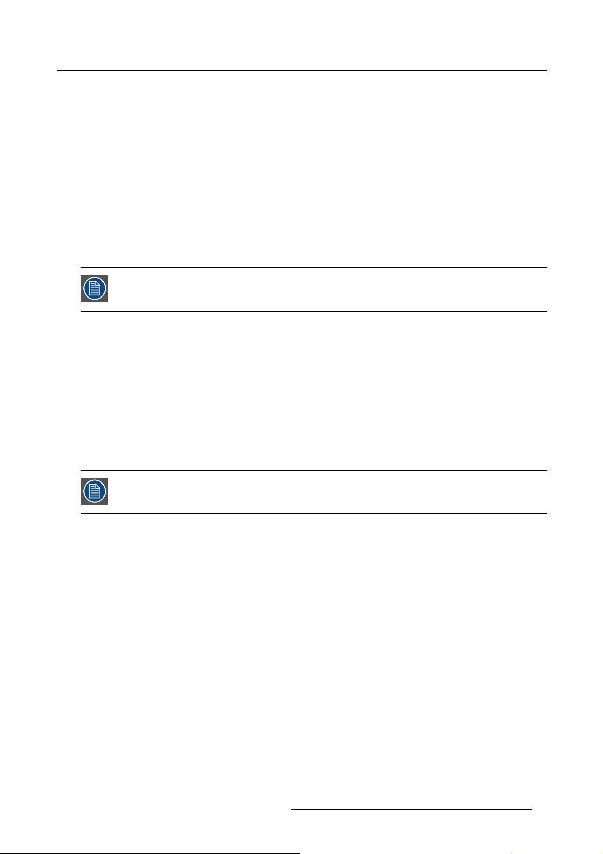
2. Check if the file is executable. This is done by right clicking on the file and selecting ‘Properties’ from
the popup menu.
3. Select tab Permissions and check if Is executable is enabled. (image 2-1)
4. Double click on the Ptoolset_installer.bin to start the installation.
5. Follow the instructions given in the different install windows.
6. The complete installation is done automatically.
r.bin) has been stored.
R59770183 PROJECTOR TOOLSET 15/07/2009
9
Page 14
2. Installation
Image 2-1
File properties
Only Projector Toolset framework is installed. To start using it, first install one or more
device plug-ins. The software will request to install the plug-ins.
2.4 Starting up
Launching Projector Toolset on Microsoft Windows
To start up the Projector Toolset software:
1. Click on Start → Programs and select Barco → Projector Toolset → Projector Toolset.
Or,
if a desk top icon is available, double click that desk top icon.
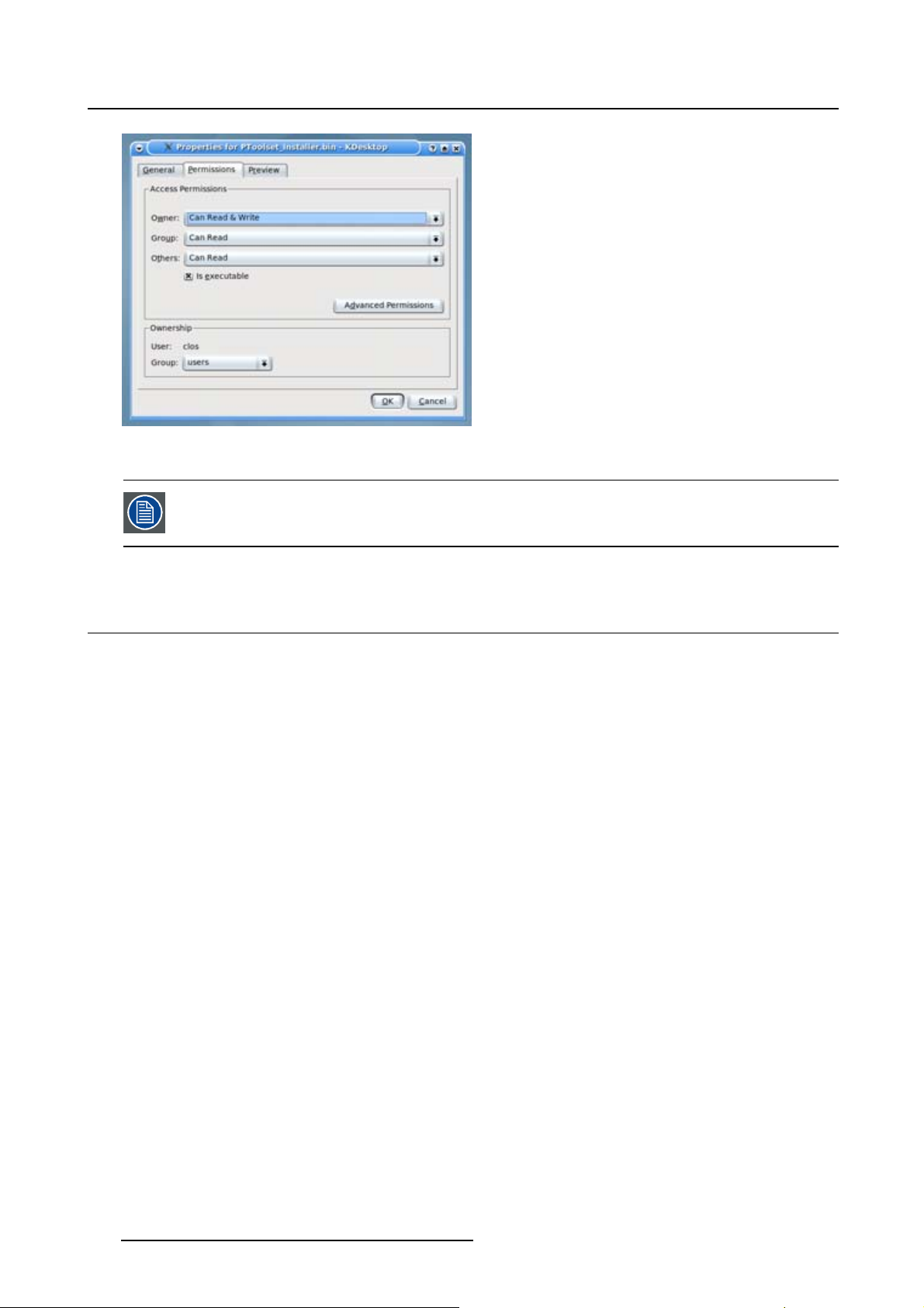
The software starts up. This start up procedure can take a while. First splash screen opens. (image 2-2)
The software starts up with the latest used configurati
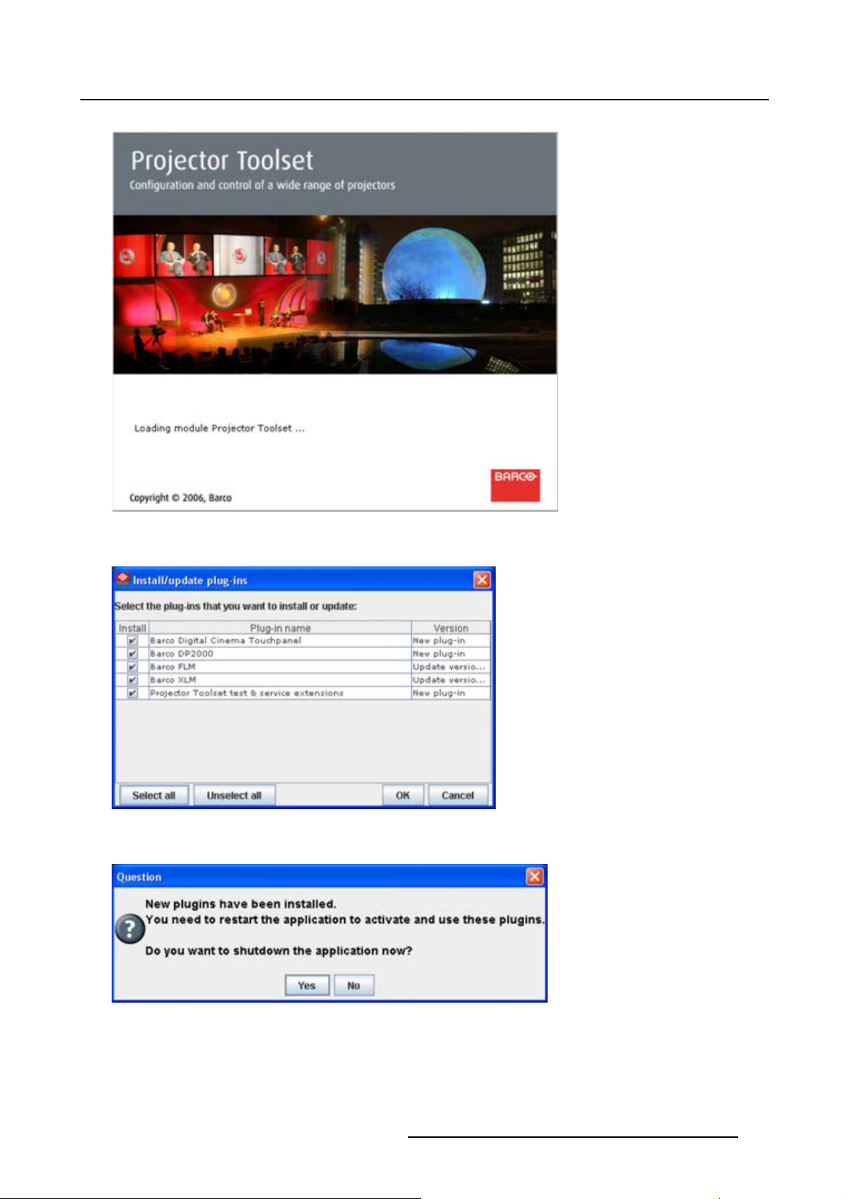
downloaded, with overview table of the downloaded plug-ins. All plug-ins in the table are selected by
default. (image 2-3)
2. Unselect the plug-ins which you do not want to install.
Or,
click on Unselect all and then select the plug-ins you want to install.
Select all will check all plug-ins at once.
3. Click OK to install the selected plug-ins.
When all plug-ins are installed, a restart message is displayed. (image 2-4)
4. Click Yes to shutdown the application and restart the application.
Click No to continue working with the old plug-ins.
on or, if new plug-ins or updated plug-ins are
10
R59770183 PROJECTOR TOOLSET 15/07/2009
Page 15
2. Installation
Image 2-2
Start up splash screen
Image 2-3
Overview downloaded plug-ins
Image 2-4
Plug-ins installed
R59770183 PROJECTOR TOOLSET 15/07/2009 11
Page 16
2. Installation
Launching Projector Toolset on Mac OS X
To start the Projector Toolset software on Mac OS X system:
1. With Finder, go to the Applications folder under your home folder.
2. Double-click on the Projector_Toolset icon to start the application.
It can take a while to start up. First splash screen opens.
The software starts up with the latest used configuration or, if new plug-ins or updated plug-ins are
downloaded, with overview table of the downloaded plug-ins. All plug-ins in the table are selected by
default. (image 2-3)
3. Unselect the plug-ins which you do not want to install.
Or,
click on Unselect all and then select the plug-ins you want to install.
Select all will check all plug-ins at once.
4. Click OK to install the selected plug-ins.
When all plug-ins are installed, a restart message is displayed. (image 2-4)
5. Click Yes to shutdown the application and restart the application.
Click No to continue working with the old plug-ins.
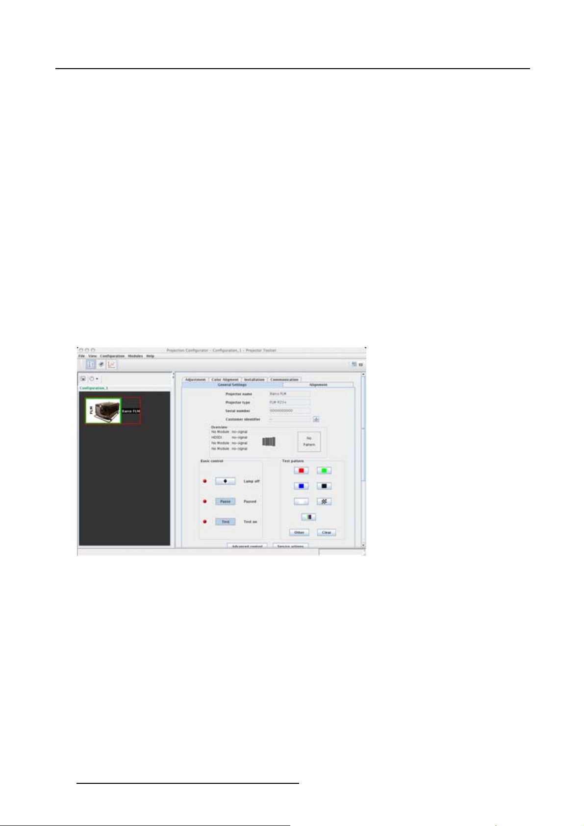
6. Once Projector Toolset is fully started, it has the following look and feel. (image 2-5)
Image 2-5
Look and feel on MAC
Launching Projector Toolset on Linux
To start the Projector Toolset software on a Linux system:
1. Go to your home folder.
2. Double click on the Projector_Toolset icon to star
It can take a while to start up. First splash screen opens.
The software starts up with the latest used configuration or, if new plug-ins or updated plug-ins are
downloaded, with overview table of the downloaded plug-ins. All plug-ins in the table are selected by
default. (image 2-3)
3. Unselect the plug-ins which you do not want to install.
Or,
click on Unselect all and then select the plug-ins you want to install.
Select all will check all plug-ins at once.
12
t the application.
R59770183 PROJECTOR TOOLSET 15/07/2009
Page 17
4. Click OK to install the selected plug-ins.
When all plug-ins are installed, a restart message is displayed. (image 2-4)
5. Click Yes to restart the application.
Click No to continue working with the old plug-ins.
6. Once Projector Toolset is fully started, it has the following look and feel. (image 2-6)
2. Installation
Image 2-6
Look and feel on Linux
2.5 Manual installation of a device plug-in
When should it be done manually
When a new plug-in is downloaded, and the user has decided no to install it yet for some reason. He still
has the possibility to install this plug-in manually.
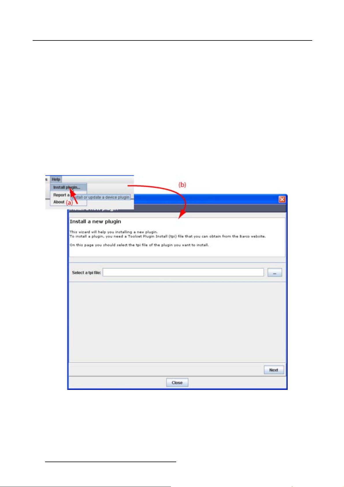
How to install
1. Start up Projector Toolset.
2. Click Help on the menu and select Install plugin... .(image2-7)
An Install device plug-in dialog box opens.
3. If the path and file name is known, fill it out next to Select a tpi file.
Or,
click on the Browse button (...).
An Open dialog box opens.
4. Browse to the desired plug-in file and cli
ck Open.
R59770183 PROJECTOR TOOLSET 15/07/2009
13
Page 18
2. Installation
Plug-in files are .tpi files and are mostly located in the Plugins subdirectory of Projector Toolset’s install
directory.
The Install device plug-in dialog is re-displayed with the complete path filled out.
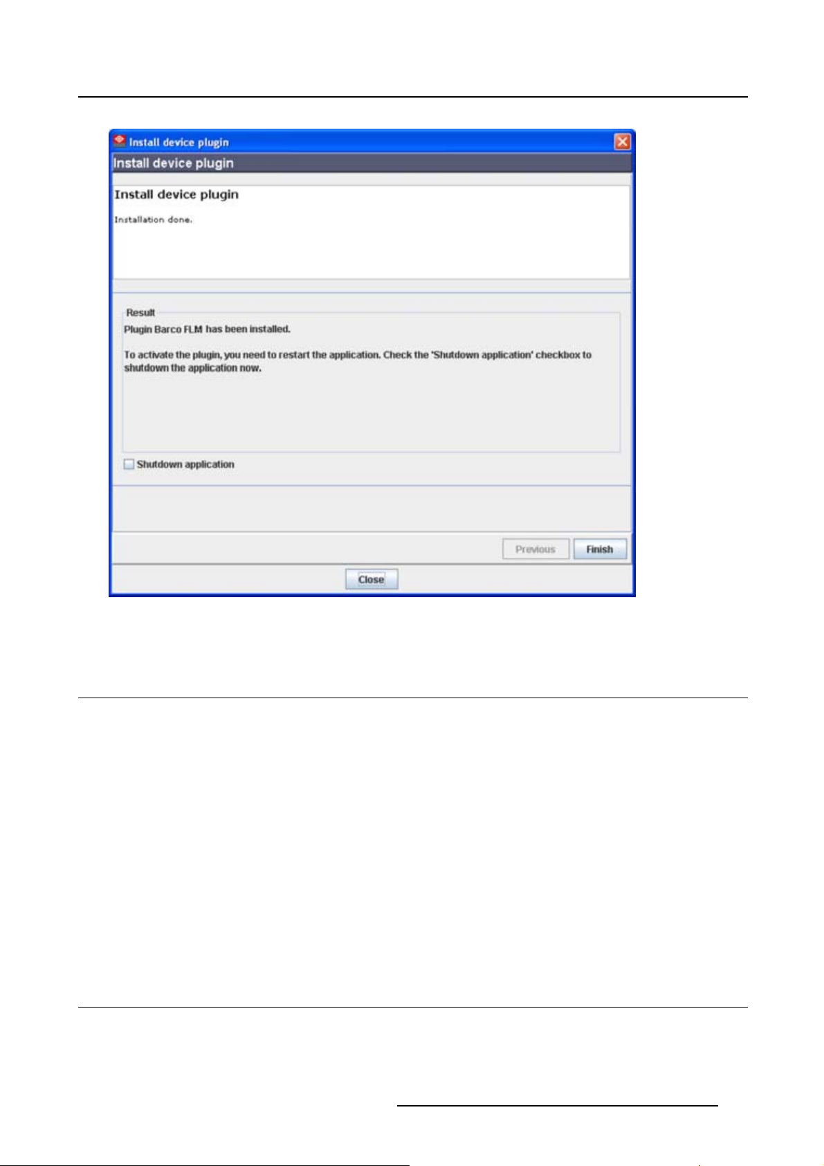
5. Click Next.
An overview of projector name, plug-in ID and version is given.
A question dialog box appears to ask if you really want to install the selected plug-in.
6. Click Next to continue.
Installation procedure starts. Result is displayed in a dialog box. A restart of Projector Toolset is necessary to activate the new installed plug-in.
7. Check Shutdown application and click Finish.(image2-8)
Projector Toolset will be closed.
8. Restart Projector Toolset.
The new plug-in is activated.
Image 2-7
Install plug-ins, start
14 R59770183 PROJECTOR TOOLSET 15/07/2009
Page 19
2. Installation
Image 2-8
Finish the installation
2.6 Uninstall Projector Toolset
How to uninstall on a Microsoft Windows platform
To uninstall the program, normal Windows functionality can be used to remove a software.
Click on Windows Start, select Settings and open Add/Remove software.
Select the version of Projector Toolset which must be removed and click on Remove.
The complete program will be removed from the hard disk.
How to uninstall on a Linux platform
Remove the Projector Toolset folder from the home folder.
How to uninstall on a Mac OS X platform
Remove the Projector Toolset folder from the application folder in the home folder.
2.7 About this manual
Overview
This Reference manual provides detailed information about the configuration and setup software Projector
Toolset. This manual is designed to be a reference tool in your everyday work with Projector Toolset.
R59770183 PROJECTOR TOOLSET 15/07/2009
15
Page 20
2. Installation
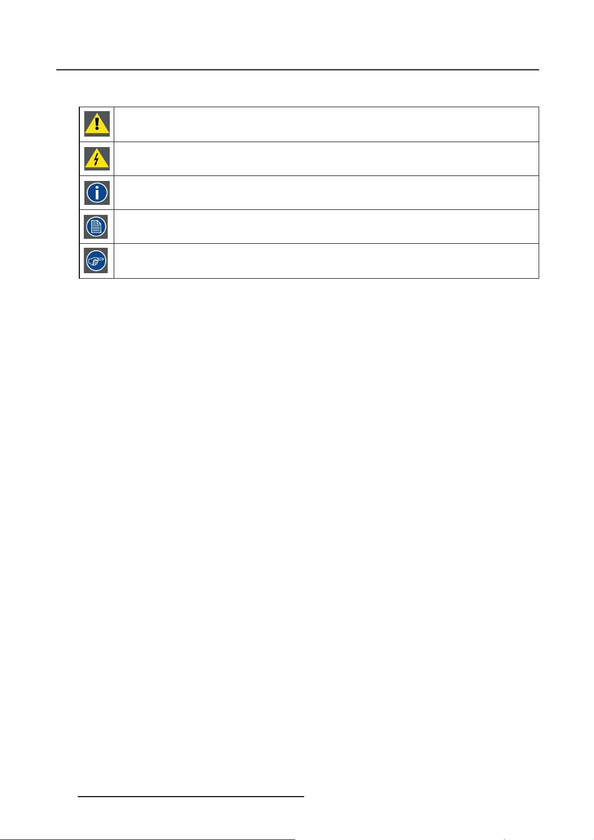
The following icons are used in the manual :
Caution
Warning
Info, term definition. General info about the term.
Note, gives extra information about the described subject.
Tip, gives extra advice about the described subject.
Images given in the manual are used as illustration. The content of the image can be slightly different with
the real image on the screen, e.g. version numbers, installed modules, etc. .
Typography:
• Clickable menu items or buttons are indicated in bold, e.g. OK
• Menu items are indicated in italic.
• A dialog window is indicated in italic, e.g. Make a new configuration.
• Step related notes, tips, warnings or cautions are printed in italic.
• Procedure related notes, tips, warnings or cautions are printed in bold between 2 lines preceding by
the corresponding icon.
What’s next?
Now that you are familiar with the style of this guide, you are now ready to know more about its modules
and what they can do.
16
R59770183 PROJECTOR TOOLSET 15/07/2009
Page 21
3. MENUS
Overview
• General
• Menu and button bar
• Main window
•Shortcutkeys
• Workspace Explorer
• How to adjust a setting
• About Projector Toolset
• Snapshot management
3.1 General
The right mouse button
The right mouse button is used in Projector Toolset for direct controls. The use of this button can be handy
throughout the complete software.
3. Menus
Ergonomics
Projector Toolset works on the principle of windows with adjustable sizes that can be positioned as you
like.
When Projector Toolset opens, it displays the main window along with the Menu and butt
drop-down menus include the usual functions of any software (File,etc.) and menus specific for Projector
To ol se t.
The button bar allows switching between the different modules.
An extra Workspace explorer window makes configuration management more easy.
on bar. The
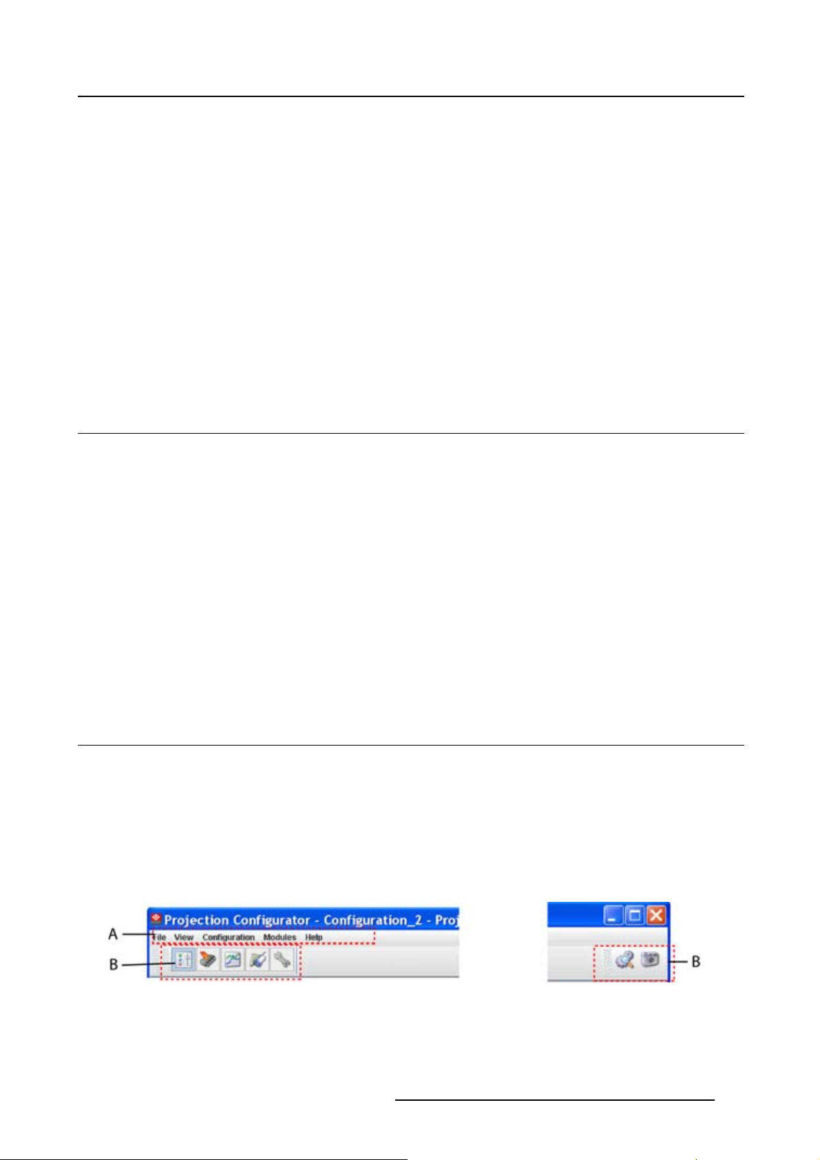
3.2 Menu and button bar
Structure
The menu contains drop down menus accessible by clicking with the mouse on an item. To select an item,
justclickonaniteminthedropdownlist.
The button bar contains on the left side navigation buttons to the different modules and on the right side
manage buttons to the workspace explorer and snapshot function
To activate a module, click on a navigation button. The window will change accordingly. When activating
some buttons, some extra items will be added to the menu.
.
Image 3-1
Menu and button bar
R59770183 PROJECTOR TOOLSET 15/07/2009 17
Page 22
3. Menus
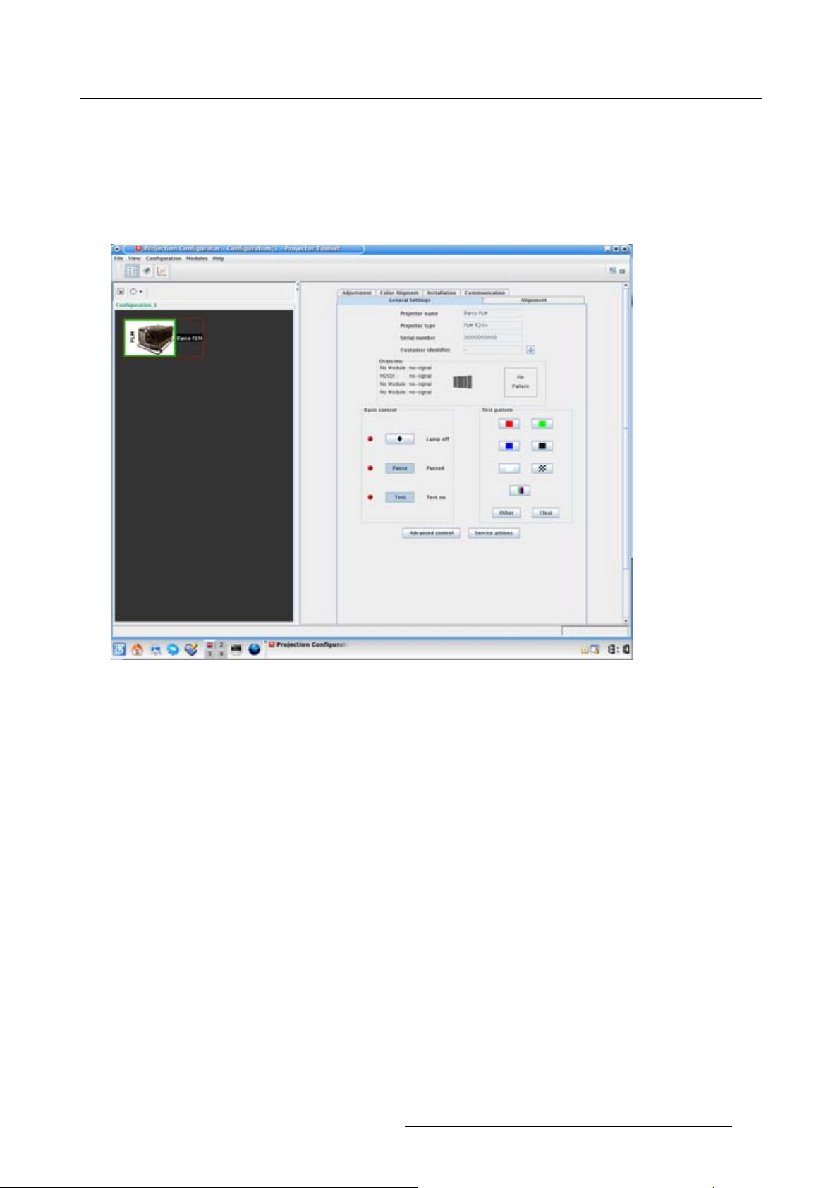
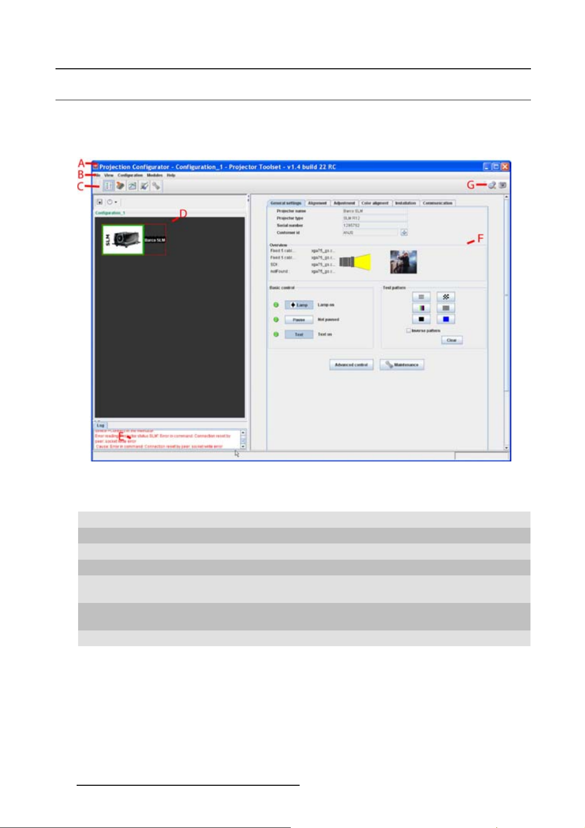
3.3 Main window
Overview
The content of the main window changes when a other navigation (module) button is activated, but the
main parts are the same for all modules.
Image 3-2
Main window indications
Indication
A
BMenu
C
D
E
F
G Manage buttons for configurations and snapshots
Description
Window title. Construction of active module - Configuration name
Module navigation buttons
Configuration preview pane
Log window. Can be hidden by the log information button on top of the configuration preview
pane.
Settings pane. Content changes with the selected module button and selected
projector/device.
Tool ti p
Some items and or icons show a tool tip when moving the cursor over that item or icon. This tool tip helps
to identify the buttons or items.
Scroll bars
If there is more information available than displayed in a pane, vertical and horizontal scroll bars will be
added to that specific pane. These scroll bars let you move up and down and left and right through the
18
R59770183 PROJECTOR TOOLSET 15/07/2009
Page 23
3. Menus
information in the pane. Vertical scroll bars are the bars on the right side of the pane. Horizontal scroll
bars are the bars at the bottom of the pane.
To use scroll bars, place the cursor on the scroll box, click and hold down the mouse button. Move the
scroll box the entire span of the scroll bar. Notice how you can move and up down in the information in
the pane.
You can also click anywhere above or below (left or right) the scroll box in the empty space. Click once
with the mouse and the scroll bar will make larger leaps in the information.
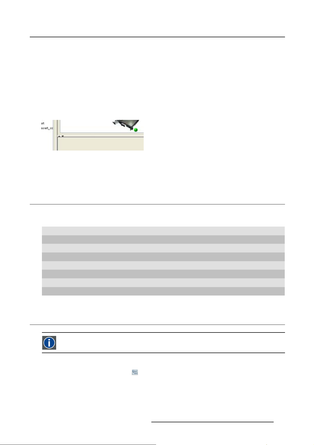
Split bar
The split bar divides the different panes. The position of the split bar is adjustable.
Image 3-3
Split bar
To adjust the position, place the cursor over the split bar separating the panes, so that the two-headed
arrow cursor appears. Click on the two-headed arrow and drag it until the panes are the desired size.
3.4 Short cut keys
Overview
Window operating system Description
F8 Take snapshot
Ctrl + F8
Shift + Ctrl + F8 Show snapshot management dialog box
F11
Alt + Enter
Ctrl + Enter Show properties of selected projector
Ctrl + S Save configuration
Shift + Ctrl + S Save all configurations
Apply snapshot
Show Workspace Explorer
Show configuration properties
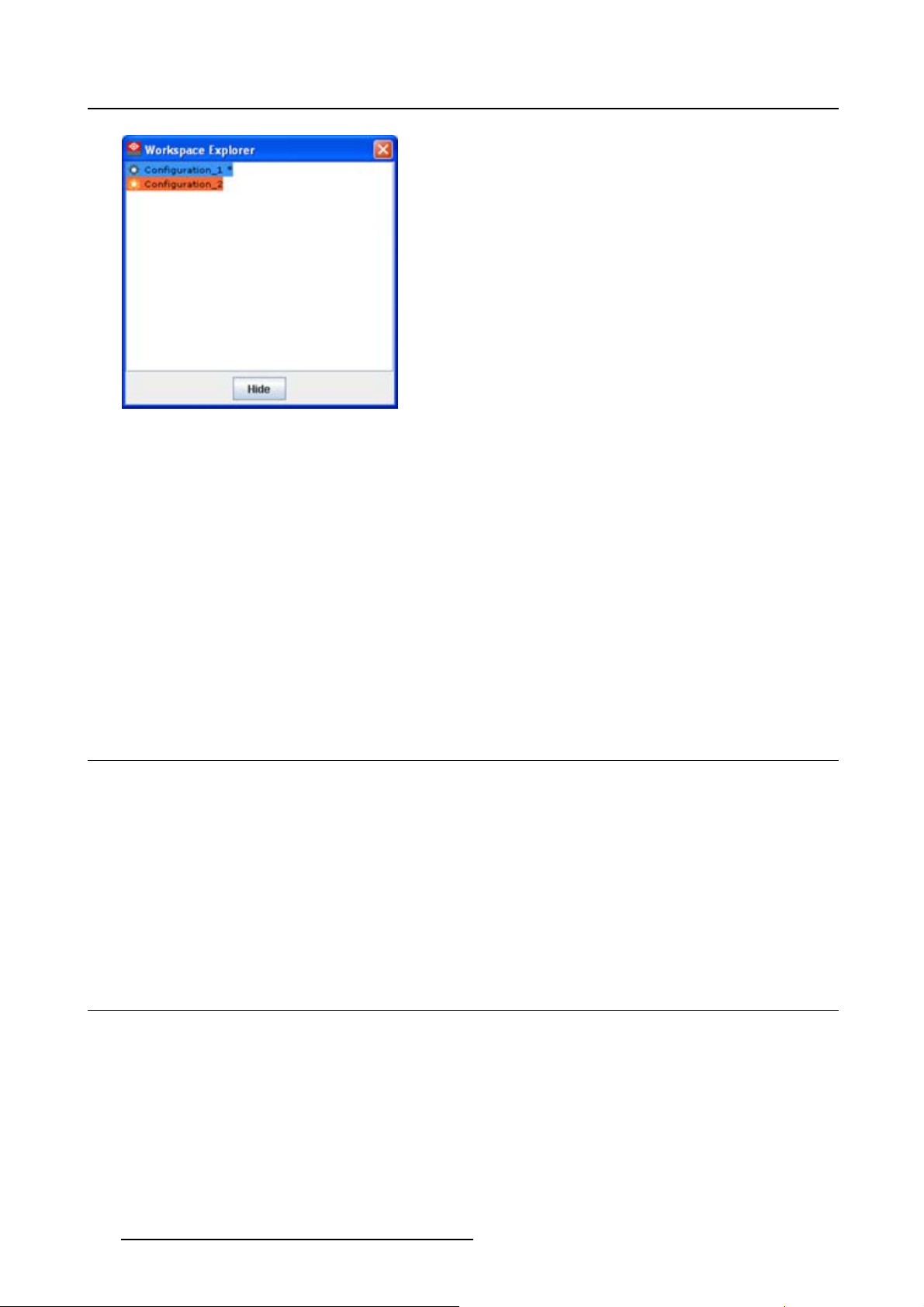
3.5 Workspace Explorer
Workspace explorer
Window to manage the available configurations in the current workspace.
How to display
Click on the workspace explorer icon ( ) on the left top corner or
on the menu, click on View → Workspace explorer or
press F11.
R59770183 PROJECTOR TOOLSET 15/07/2009
19
Page 24
3. Menus
Image 3-4
Workspace explorer
What can be done
The workspace explorer window gives an overview of the existing Configurations.
To select a configuration, just click on it. The background of the selected configuration changes to blue.
When the same item is open (active) the background remains blue.
When another configuration is selected, the background of this new configuration becomes blue and the
background of the active (open) configuration changes to orange.
To activate (open) another configuration, double click on it. The background becomes blue. All other
configurations will have no background.
An asterisk (*) behind a configuration means that a configuration setting is changed since the last saved
version. A save is necessary to store the changes.
3.6 How to adjust a setting
About input boxes
To change a value:
• Click on the up down control of the spin box next to the input box until the desired value is reached.
• Click in the input field of the spin box, select the act
ual value and enter a new value with your keyboard.
About drop down menu settings
Click on the drop down menu. A list of possible choices opens. Select the desired item.
3.7 About Projector Toolset
Why?
The about function in the Help menu gives a
modules. This information can be handy when calling for help.
The images given below are just example images. These images can differ from version to version.
20
n overview of the used system parameters and the installed
R59770183 PROJECTOR TOOLSET 15/07/2009
Page 25
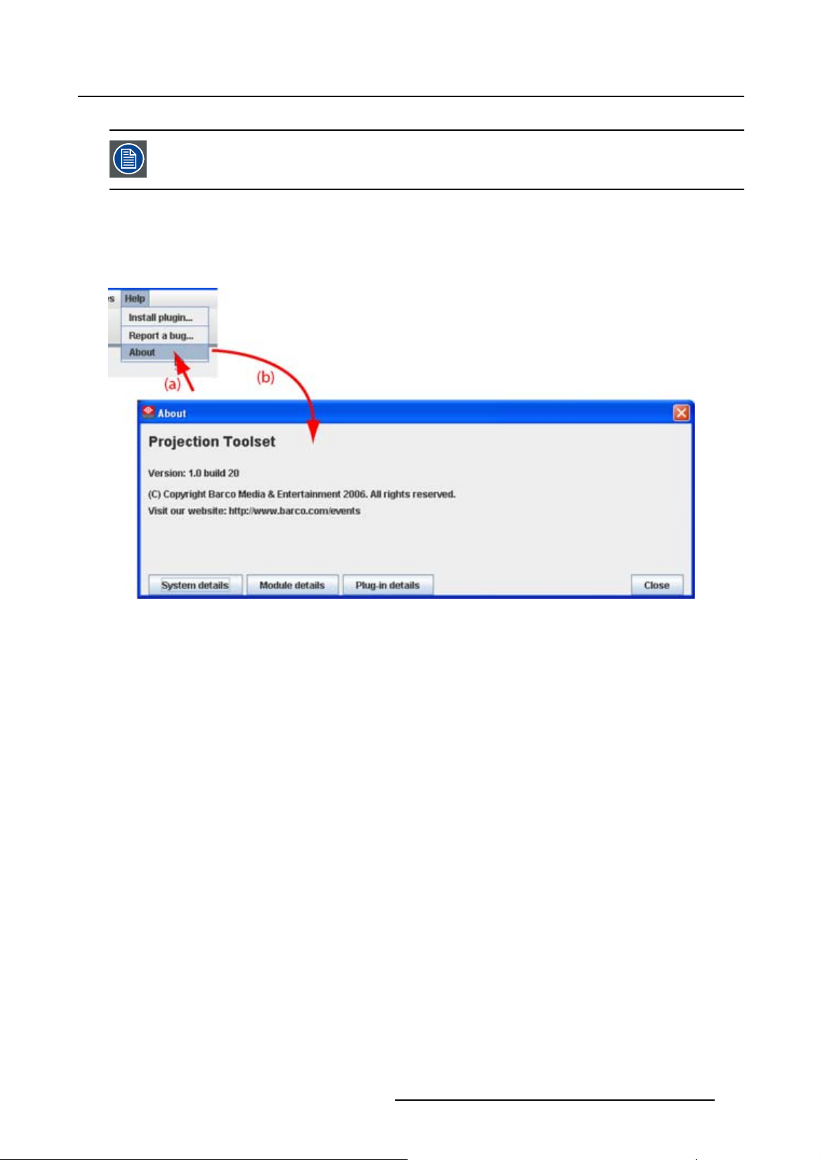
The versions indicated on the illustrations are only given as info and these versions can
be different with the current versions.
How to start up
Click Help on the menu and select About (a). (image 3-5)
The About start up dialog box opens (b).
3. Menus
Image 3-5
About window
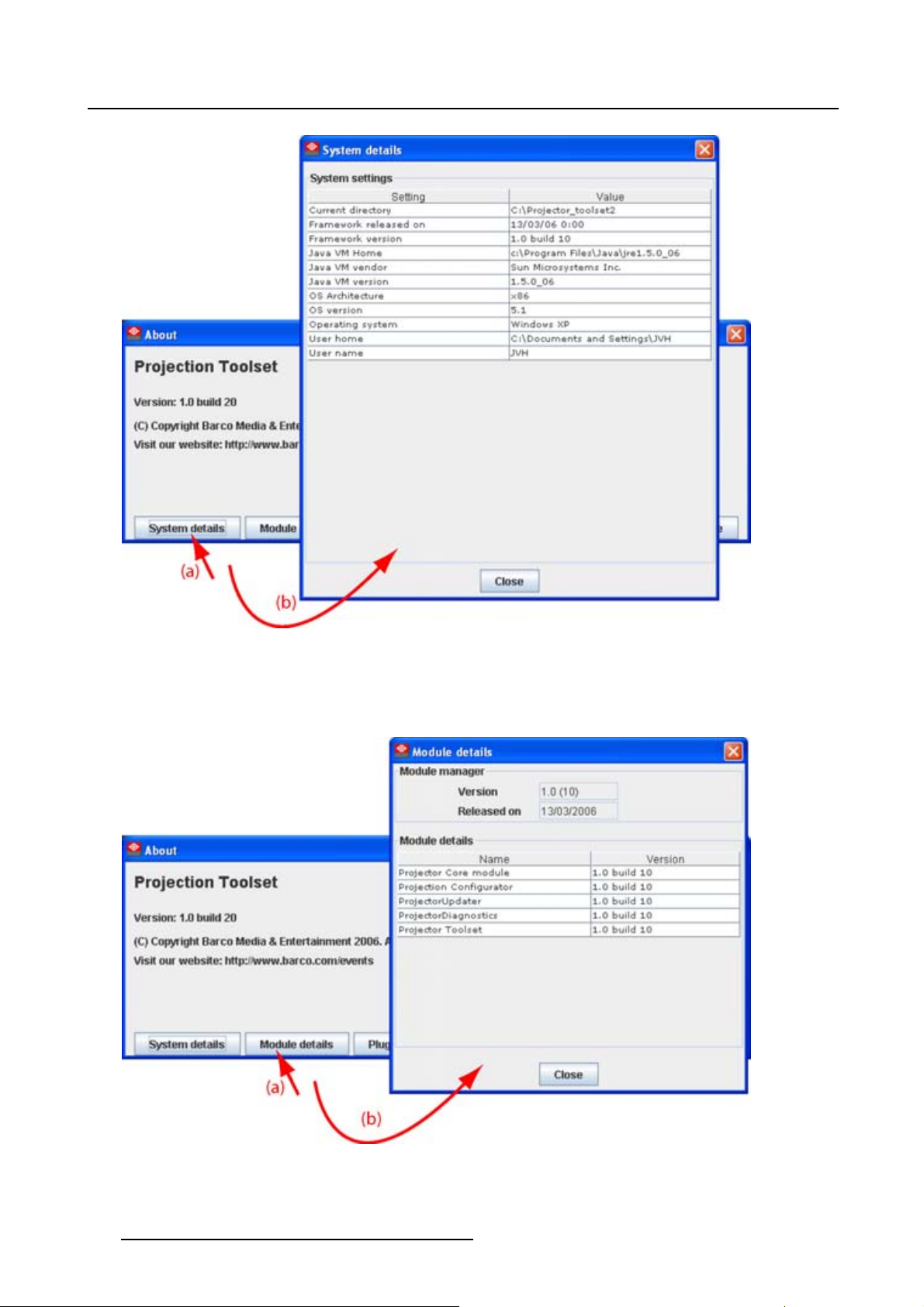
System details
Click on System details to see the system parameters on which Projector Toolset is running.
R59770183 PROJECTOR TOOLSET 15/07/2009
21
Page 26
3. Menus
Image 3-6
System details
Module details
Click on Module details to get an overview of the installed modules.
Image 3-7
Module details
22 R59770183 PROJECTOR TOOLSET 15/07/2009
Page 27
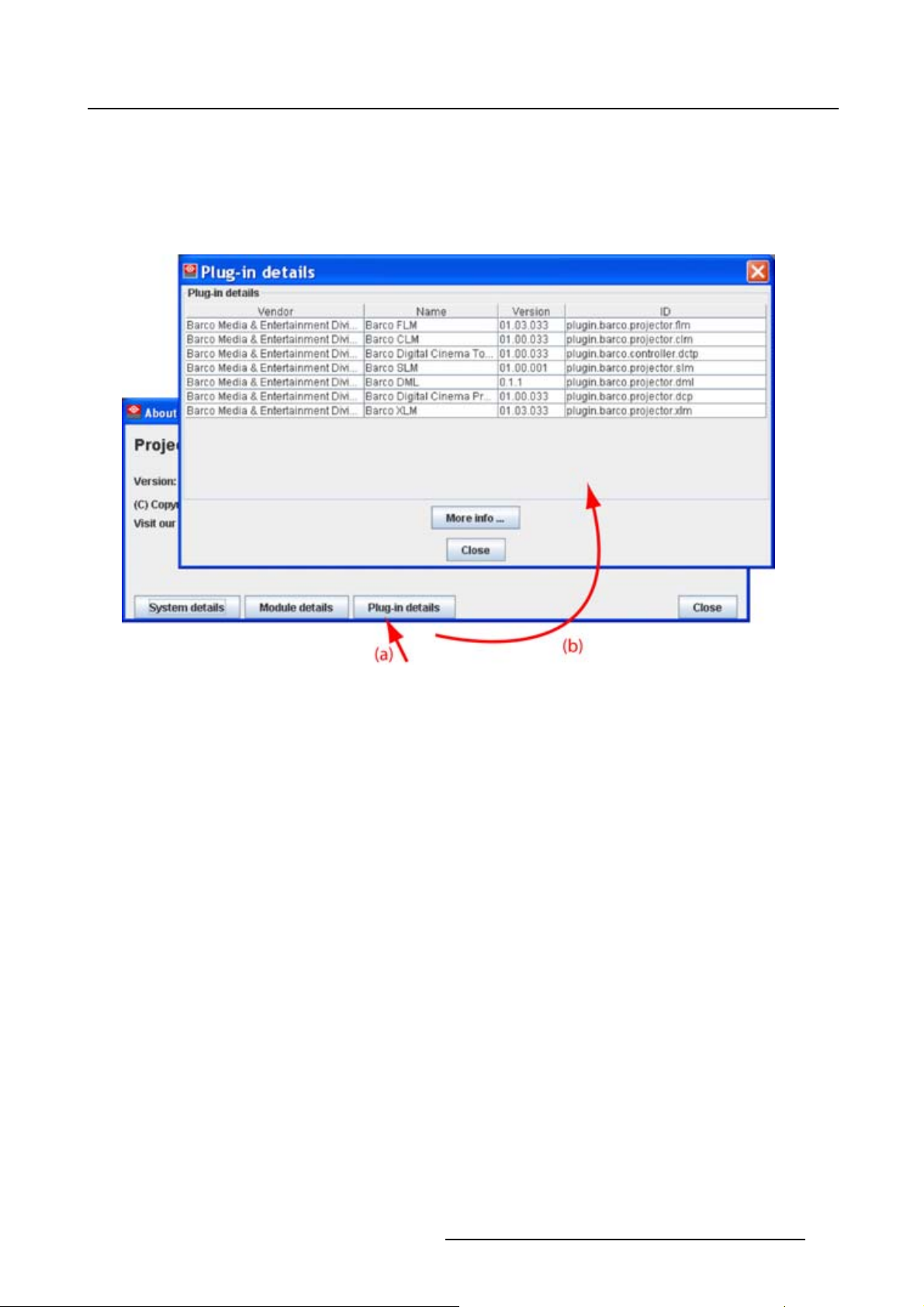
First of all the software version and the release date are indicated in Module manager.
Module details gives an overview of the installed modules and their version.
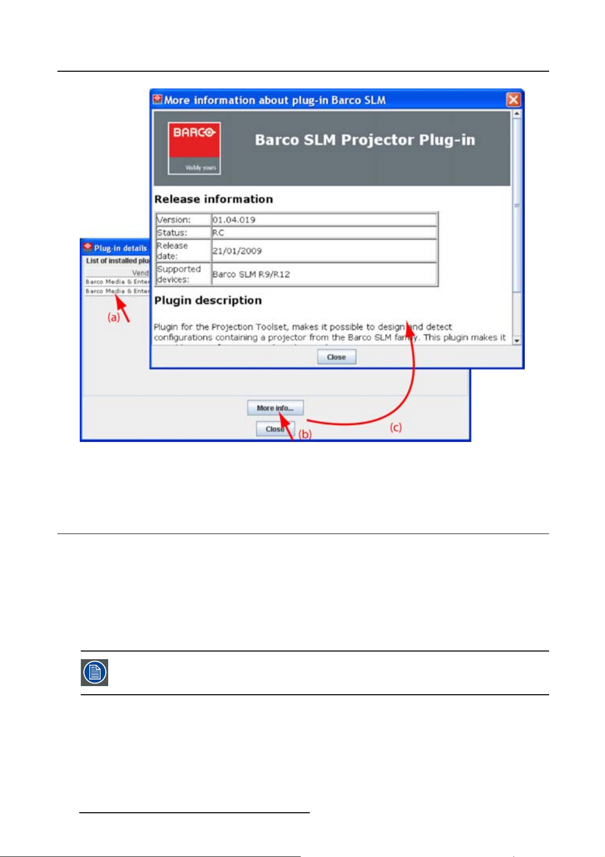
Plug-in details
Plug-in details gives an overview of the installed device plug-in together with their version.
3. Menus
Image 3-8
Device plug-ins details
For more info about a device plug-in, click on the desired plug-in to select and then click on More info... .
R59770183 PROJECTOR TOOLSET 15/07/2009
23
Page 28
3. Menus
Image 3-9
More info device plug-in
Release information, plug-in description and license agreement is given.
3.8 Snapshot management
• About snapshots
• Managing snapshots
• Take a snapshot
• Apply a snapshot
• Delete a snapshot
• Add shot cut key to a snapshot
• Remove shot cut key association
When a configuration contains also Digital Cinema Touch panel devices or only these
devices, these devices are not included in a snapshot.
3.8.1 About snapshots
Overview
At any moment the settings for a configuration can be saved in a snapshot file. This snapshot file can be
loaded again to create the same situation as when the snapshot was taken.
24
R59770183 PROJECTOR TOOLSET 15/07/2009
Page 29

A snapshot can contain:
• All settings
• All layout settings
• All input settings
• Lamp settings
• Projector settings
Snapshot
A snapshot is a collection of settings at a given point of time for a configuration
3.8.2 Managing snapshots
Overview
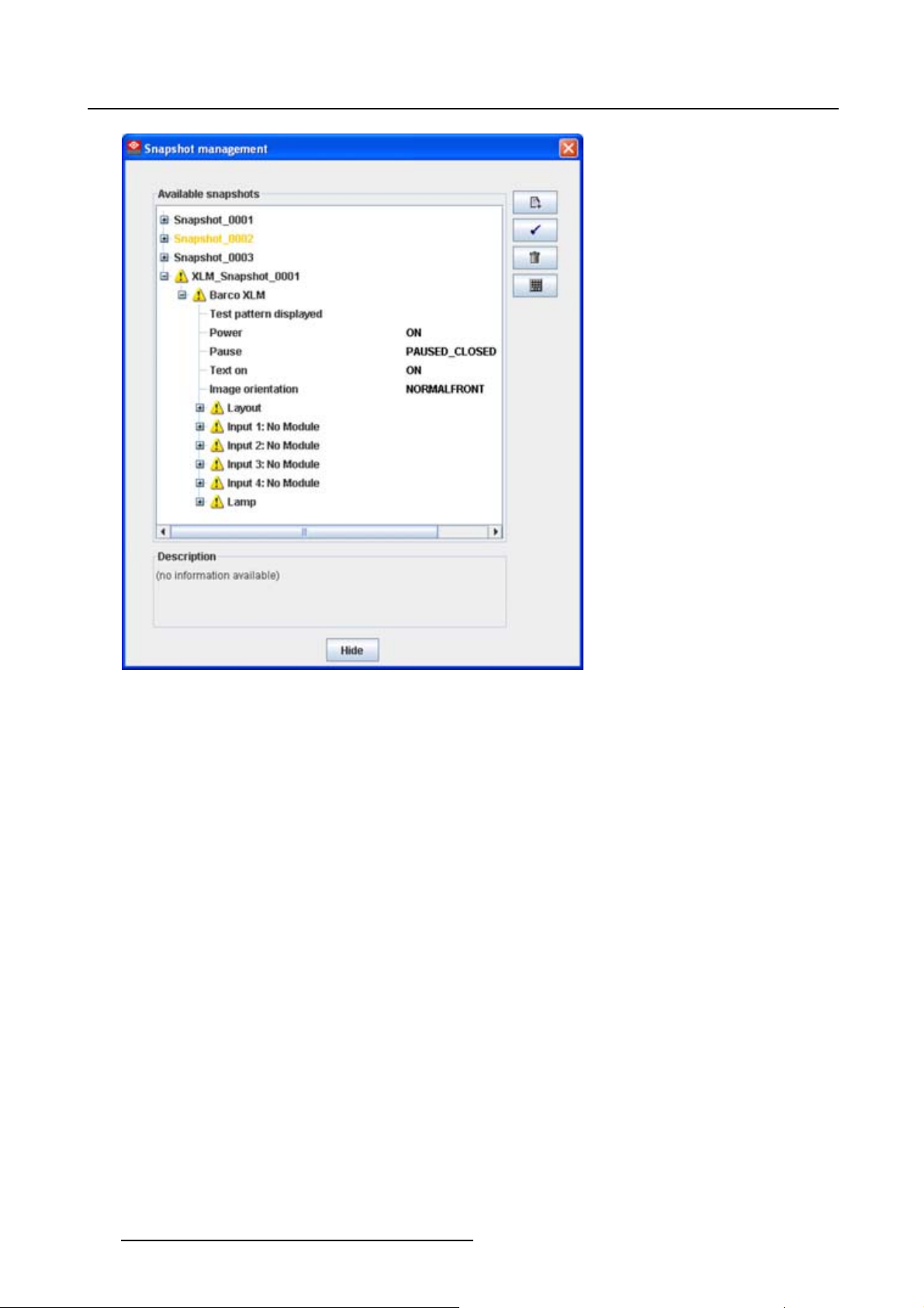
When opening the snapshot window an overview of all available snapshots is given. A snapshot file is
built up as a tree of settings.
To open this tree of settings, click on the ’+’ sign to expand a branch.
A yellow warning symbol in front of the snapshot name means that something inside the snapshot does
not correspond with the current active configuration. Expand the snapshot tree to see the differences.
Such a snapshot can be applied to the current configuration but only the corresponding setting are loaded
and for the other settings, the current values remain in place.
3. Menus
Some examples when a warning symbol can be displayed:
• projector not (anymore) in the configuration
• inputs on projector are swapped, or missing.
When a snapshot is selected, the name of the snapshot is yellow.
R59770183 PROJECTOR TOOLSET 15/07/2009
25
Page 30
3. Menus
Image 3-10
Snapshot view
3.8.3 Take a snapshot
What can be done?
As a snapshot is collection of setting at a certain point in time, a snapshot of the current configuration can
be taken at any moment.
How to take
Click on the snapshot icon on the manage button bar (a). (image 3-11)
The Snapshot management dialog box opens (b).
Click the Take a snapshot icon (c).
The Take a snapshot dialog box opens (d).
To change the proposed snapshot name, click in the input field next to Snapshot name, select the current
name and enter a new name (e).
Note: Only the characters a to z, A to Z, 1 to 9 and (, ), _, -, @ or allowed in a name.
To enter a description for the snapshot, click in the description input field and enter a description (f).
To select the snapshot level, click on the drop down box next to Snapshot level and select the desired
level from the list (g).
26
R59770183 PROJECTOR TOOLSET 15/07/2009
Page 31

3. Menus
The following levels are available:
- All settings
- All layout settings: only layout settings are saved
- All input settings: only input settings are saved
- Lamp settings: only lamp settings are saved
- Projector settings: only projector settings are saved
This is a first filtering level and can be followed by a device selection.
Select the device. By default all devices are selected (h).
Within the setup snapshot level it is possible to exclude some devices by un-checking that device in
Select the device.
E.g. when selecting as snapshot level lamp settings, it is possible to exclude the lamp settings of a
certain projector or when selecting input settings, it is still possible to exclude some inputs.
Click OK to take the snapshot (i).
The snapshot is taken. A message is displayed with the result.
Click OK to finish the snapshot procedure.
Image 3-11
Take snapshot
R59770183 PROJECTOR TOOLSET 15/07/2009 27
Page 32

3. Menus
3.8.4 Apply a snapshot
What can be done?
A snapshot can be fully or partially apply to the current configuration.
When there is no warning symbol in front of the snapshot name, this snapshot can be fully applied to the
current configuration.
When there is a warning symbol in front of the snapshot name, that means that the current configuration
is not the same as those when the snapshot was made, than only the matching parts will be applied to the
current configuration. To see which items do not match, expand the snapshot. Each not matching item
will have a warning symbol.
How to apply
Click on the snapshot icon on the manage button bar (a). (image 3-12)
The Snapshot management dialog box opens with all available snapshots (b).
Click on the desired snapshot (c).
The name becomes yellow.
ClickontheApplyicon(d).
A Load and apply question dialog box opens (e).
Click Yes to apply (f).
When it was a fully match, all items in the snapshot are applied. In all other cases a not matching dialog
box opens that indicate all not matching items (g).
Click Yes if you want to continue apply the matching items (h).
28
R59770183 PROJECTOR TOOLSET 15/07/2009
Page 33

3. Menus
Image 3-12
Apply snapshot
3.8.5 Delete a snapshot
How to delete
Click on the snapshot icon on the manage button bar (a). (image 3-13)
The Snapshot management dialog box opens with all available snapshots (b).
Click on the snapshot to delete (c).
The name becomes yellow.
Click on the delete icon (d).
Aconfirmation dialog box is displayed (e).
Click Yes to delete (f).
R59770183 PROJECTOR TOOLSET 15/07/2009
29
Page 34

3. Menus
Image 3-13
Delete snapshot
3.8.6 Add shot cut key to a snapshot
What can be done?
To each snapshot a key stroke can be associated so that it can be used as short cut key. This short cut
key can be activated at any time. Depending on the apply settings, the snapshot will be loaded without
any notice or will be loaded after aski
be refreshed.
ng for confirmation. Once the snapshot is loaded, the statuses will
Howtocreateashortcutkey
Click on the snapshot icon on the manage button bar (a) (image 3-14)
The Snapshot management dialog box opens with all available snapshots (b).
Click on the key bindings icon (c).
The Snapshot trigger keybinding
Select the snapshot to add a keybinding (e).
Enter a keystroke (f).
No combination of keys is possible. Only single key can be used.
Select the snapshot trigger by clic
- Don’t apply: not happens when activating the key.
- Apply after confirmation: once the key is pressed, a confirmation message is displayed.
- Apply immediately: once the key is pressed, the snapshot is applied without displaying any message.
dialog box opens (d).
king on the radio button (g).
30
R59770183 PROJECTOR TOOLSET 15/07/2009
Page 35

Click OK to save the new short cut status (h).
3. Menus
Image 3-14
Associate short cut to snapshot
3.8.7 Remove shot cut key association
How to remove a short cut
Click on the snapshot icon on the manage button bar (a) (image 3-15)
The Snapshot management dialog box opens with all available snapshots (b).
Click on the key bindings icon (c).
The Snapshot trigger keybinding dialog box opens (d).
To clear the key for a specific snapshot, select that snapshot (e) and click Clear (f1).
To clear all short cut keys at once, click on Clear all (f2).
Click OK to save the new short cut s
tatus (g).
R59770183 PROJECTOR TOOLSET 15/07/2009
31
Page 36

3. Menus
Image 3-15
Clear short cut on snapshot
32 R59770183 PROJECTOR TOOLSET 15/07/2009
Page 37

4. Preferences
4. PREFERENCES
• Introduction
• Start up the preferences
• Access level
• Software Appearance
• Bug report setup
• Logging
• Workspace selection
4.1 Introduction
Overview
Preferences determine the default behavior of the software. Some preferences can be generally set for
the complete software, some others are only for the different plug-in modules.
4.2 Start up the preferences
How to start up ?
Click on File onthemenubar. (image4-1)
The file menu opens.
Select Preferences... .
The Preference dialog box opens. (image 4-2)
Use the Show all button to display all the preference items. This Show all buttons is available in all
following sub preference windows.
Use Apply button to apply a preference change in one of the other module.
Use Cancel to ignore the preference changes.
Use OK to apply the preference changes and to close the window at the same time.
Image 4-1
Select Preferences
R59770183 PROJECTOR TOOLSET 15/07/2009 33
Page 38

4. Preferences
Image 4-2
Preference window
4.3 Access level
What can be done ?
Some actions and functions of the Projector Toolset are restricted to certain access levels. In this panel
you can check the access level and read information from a dongle, if you have one.
A dongle is not required to use the normal functions in Projector Toolset.
When using Projector Toolset without dongle, or as operator, the maintenance function in the Service
module has the same content as the maintenance button in the Configurator module, General tab.
34
R59770183 PROJECTOR TOOLSET 15/07/2009
Page 39

4. Preferences
Image 4-3
Access levels
To read out the dongle settings, click on Read dongle. The current level of the inserted dongle is indicated
next to User level.
4 different levels are defined:
• operator level
• service technician level
• theatre technician level
• Barco technician level
Each level can access specific functions in the service
described in this manual.
module. Only the operator level functions are
4.4 Software Appearance
What can be changed ?
The following items can be changed:
• Language of the software.
• Look and feel of the software.
Language selection
Click on Appearance (image 4-2).
The appearance window opens.
ClickonthecomboboxnexttoAppearance of the application.(image4-4)
The possible languages will be displayed.
Select the desired language.
Click on Apply to confirm the selection.
An info window will be displayed to announce that the language change will take place after restarting
the software.
R59770183 PROJECTOR TOOLSET 15/07/2009
35
Page 40

4. Preferences
Image 4-4
Language selection
Look and feel of the software
Click on Appearance (image 4-2).
The appearance window opens.
Click on the combo box next to Look and Feel.(image4-5)
The possible look and feels will be displayed.
The following are possible:
- Windows
-Java
An info window will be displayed to announce that the look and feel change will take place after restarting
the software.
36
R59770183 PROJECTOR TOOLSET 15/07/2009
Page 41

4. Preferences
Image 4-5
Look and feel software
Screen shots in this manual are made for a Java look and feel.
Use of specific fond
Click on Appearance (image 4-2).
The appearance window opens.
Check the check box in front of Use specific font. (image 4-6)
The drop down menu becomes available.
Click on the drop down box and select the desired font.
Click on Apply to confirm the selection.
An info window will be displayed to announce that the look and feel change will take place after restarting
the software.
R59770183 PROJECTOR TOOLSET 15/07/2009
37
Page 42

4. Preferences
Image 4-6
Use of specific font
4.5 Bug report setup
SMTP
SMTP (Simple Mail Transfer Protocol) is a TCP/IP protocol used in sending E-mail.
Setup bug report
Click on Bug reporting. (image 4-7)
The bug report setup window appears. (image 4-8)
Bug reporting is by default enabled.
Fill out the Personal data.
This personal data will be incorporated in the bug
Personal data contains the following information :
- First name
-Lastname
- Organization
- E-mail address
- Telephone number
- Mobile number
report so that Barco can contact you.
Click on Edit mail settings.
The mail settings window opens. (image 4-9)
Fill out Your mail account settings.
38
R59770183 PROJECTOR TOOLSET 15/07/2009
Page 43

4. Preferences
The following settings should be entered :
- Your E-mail address
- Organization
- Barco’s E-mail address, automatically filled out when installing the software.
If you want to receive a copy of the bug report E-mail to Barco, check this check box.
Fill out the address of the SMTP mail server.
Tip: Contact your system administrator in your organization to obtain the correct address.
Fill out the port of the mail server. Your system administrator can help you. The port is default set on 25.
Click OK.
Image 4-7
Bug report selection
Image 4-9
Mail setup window
4.6 Logging
Start up
Image 4-8
Bug report setup window
Click on Logging.
The logging preferences window opens. (image 4-10)
R59770183 PROJECTOR TOOLSET 15/07/2009
39
Page 44

4. Preferences
Image 4-10
Logging and debugging preferences
Logging level
Click on the slider bar to set the desired logging level.
The following levels are possible:
• Debug
•Info
• Error
• Warning
•Fatal
Message to log file
The logging about the behavior of the program can be logged in a file. Each time the program is started a
new log file is created. The file is saved in a subdirectory log of the Projector Toolset install directory. The
file name contains the date and the sequence of start up
The logging level can be set to limit the number of data. By default, Info level is setup. Other levels are
Debug, Warning, Error and Fatal.
Check the check box in front of Write log messages to file if you want to activate the logging. This is a
preferred setting.
The period a logging must be saved on disk can be set. Default set to 20 days. All logging older than 20
days will be removed.
at that date.
When the period is set to “0”, only the last created logging will remain on the disk.
To clear the complete logging directory, click once on Clear all.
4.7 Workspace selection
Start up
Click on Workspace selection.(image4-11
40
)
R59770183 PROJECTOR TOOLSET 15/07/2009
Page 45

4. Preferences
The workspace selection dialog box opens.
To change to another workspace, click on the drop down box and select the desired workspace. (im-
age 4-12)
Or,
click on ... to open an Open dialog box (a2).
Browse to a workspace or enter a new workspace in the File name field.
Click on Open (b).
The current configurations will be closed.
Click on Apply to apply the new workspace (c).
Image 4-11
Select Workspace preferences
R59770183 PROJECTOR TOOLSET 15/07/2009 41
Page 46

4. Preferences
Image 4-12
Selecting a workspace
42 R59770183 PROJECTOR TOOLSET 15/07/2009
Page 47

5. CONFIGURATOR
• Introduction
•Configurator window
• Create a new configuration
• Add projector to a configuration
• Reconnect a projector
• Move projector to a group
• Edit projector properties
•Configuration preview
•Configuration properties
•Configuration properties, new group
• Preview layout properties
• Multiple projector selection
5.1 Introduction
5. Configurator
Overview
The configurator makes it possible to create configurations and to change the settings of each device
separately.
Start up
To start up the configurator, just click on the configurator icon ( ) on the navigation button bar or click
on Modules and select Configurator.
Image 5-1
Configurator start up
5.2 Configurator window
Overview
The configurator window allows to create new configurations and to manage the projectors inside a con-
figuration.
5.3 Create a new configuration
Stepstobetaken
Click File onthemenuandselectNew → New configuration (a). (image 5-2)
R59770183 PROJECTOR TOOLSET 15/07/2009
43
Page 48

5. Configurator
Or,
press Ctrl + N.
The New configuration dialog box opens (b).
Fill out a name for the new configuration next to Configuration name. The default name will be Configu-
ration_’digit’ (c).
Note: Only the characters a to z, A to Z, 1 to 9 and (, ), _, -, @ or allowed in a name.
When it is the first configuration for this workspace, only the option Create by adding projectors is available.
When there are already configuration available, the option Basedonavailableconfiguration becomes
available
Check the radio button of your choice (d).
When Based on available configuration is checked, click on the combo box and select the configuration
on which the new configuration must be based on (e).
Click OK to create the new configuration (f).
Image 5-2
Create new configuration
5.4 Add projector to a configuration
• Add projector
• General properties
• Connection setup
• Decorator setup
5.4.1 Add projector
The possible projectors types depends on the installed plug-ins.
44 R59770183 PROJECTOR TOOLSET 15/07/2009
Page 49

5. Configurator
About adding a projector
To m a k e i t m or e e a sy t o find back a projector while adding it to the software, the different projectors are
grouped in categories.
The following categories are available for the moment (depending on the loaded plug-ins):
• Digital cinema: this category contains all supported digital cinema projectors and touch panels.
• Mid venue: this category contains all supported projectors from the CLM and SLM series.
• Large venue: this category contains all supported projectors from the FLM series.
• XLarge venue: this category contains all supported projectors from the XLM series.
How to add
Click Configuration on the menu and select Add (a). (image 5-3)
Move the cursor to the right and select the desired category.
Move the cursor again to right and select the desired projector.
The Create projector dialog box opens with the selected device type pictograph at the right side (b).
Enter the different device properties such as the projector identification, the connection parameters and
projector decorator for the configuration preview.
Image 5-3
Add projector
When adding twice the same projector, once via a network connection and once via a
serial connection, a message will be displayed to warn the user that there is already an
instance with the same projector and that problems with the communication are possible. The projector will be added but Projector Toolset advises to uninstall one of the
connections.
R59770183 PROJECTOR TOOLSET 15/07/2009 45
Page 50

5. Configurator
5.4.2 General properties
Overview
Click on the General tab to open the general properties if not yet open (a).
Image 5-4
General projector properties
Projector’s identification
The default display name is Barco followed by the project
This name can be changed to any other name. Click in the name field, select the current name and enter
a new name (b).
Next to the display name, the device type is indicate with the name and a device icon.
or type.
Projector status
Indicates the communication status of the projector (c).
• enabled: communication with projector possible
• disabled: no communication with projector possible
5.4.3 Connection setup
• Set up a serial connection
• Set up a Ethernet connection
No serial connection possible when using Projector Toolset on MAC OS X or on a Linux
system !
46 R59770183 PROJECTOR TOOLSET 15/07/2009
Page 51

5. Configurator
5.4.3.1 Set up a serial connection
Only possible when Projector Toolset runs on a Microsoft Windows platform.
Physical connection
Before a serial connection can be made, connect a serial cable from PC to the RS232IN connector of the
projector.
RS232
An Electronic Industries Association (EIA) serial digital interface standard specifying the characteristics of the communication path between two devices using either D-SUB 9 pins or D-SUB
25 pins connectors. This standard is used for relatively short-range communications and does
not specify balanced control lines. RS-232 is a serial control standard with a set number of
conductors, data rate, word length and type of connector to be used. The standard specifies
component connection standards with regard to computer interface. It is also called RS-232-C,
which is the third version of the RS-232 standard, and is functionally identical to the CCITT V.24
standard. Logical ’0’ is > + 3V, Logical ’1’ is < - 3V. The range between -3V and +3V is the transition zone.
Necessary parts
Straight serial cable
Software connection
Select the Connection properties tab (a). (image 5-5)
The right pane changes to the connection setup page.
Click on the radio button next to A projector connected to a serial port to select the serial connection (b).
Click in the Projector address input field and enter the projector address (c).
This address must be between 0 and 255.
Select the serial port of your PC connected with the projector. Click on the drop down box and select the
corresponding port (d).
Click OK to make the connection.
R59770183 PROJECTOR TOOLSET 15/07/2009
47
Page 52

5. Configurator
Image 5-5
Set up a serial connection
Scan projector
If the projector address and the communication port are not known, click on Device scan to get an
overview of the serial connected projectors (a).
48
R59770183 PROJECTOR TOOLSET 15/07/2009
Page 53

5. Configurator
Image 5-6
Detect serial connected projectors
Fill out the address range (b) and click Start detection (c).
A Serial scan result dialog box opens.
Select the desired projector (d) and click Open (e). A connection is made with the selected projector.
5.4.3.2 Set up a Ethernet connection
Possibilities
To establish a Ethernet connection, the following ways are possible:
• Enter an IP address
• Enter a host name
• Scan the net work for the connected projectors
IP
Internet Protocol. The network layer of TCP/IP. Required for communication with the internet.
R59770183 PROJECTOR TOOLSET 15/07/2009 49
Page 54

5. Configurator
Host name
This is the name that will be returned, along with the IP address in response to the UDP broadcast query for projectors/touch panels.
DNS server
Computers, Projectors, Touch panels connected to a network are referenced by their IP address. The only problem is that remembering IP addresses is not easy. If you need to use
hundreds of addresses then it will become impossible to remember them. This is why domain
names are created. Internet names (domain and host names) are just aliases to these IP addresses. When you use an Internet address it is automatically translated to an IP address. In
fact a program or device that translates those Internet names to IP addresses is called a DNS
Server.
Via entering an IP address
Select the Connection properties tab (a). (image 5-7)
The right pane changes to the connection setup page.
ClickontheradiobuttonnexttoA projector connected on the network to select the Ethernet connection
(b).
Click on the radio button in front of IP address (c).
Enter the IP address (d).
Note: An address contains 4 octets with a maximum value of 255.
Click OK to make the connection.
Image 5-7
Make connection via entering IP address
Via entering a host name
Select the Connection properties tab (a). (image 5-8)
The right pane changes to the connection setup page.
ClickontheradiobuttonnexttoA projector connected on the network to select the Ethernet connection
(b).
Click on the radio button in front of Host name (c).
50
R59770183 PROJECTOR TOOLSET 15/07/2009
Page 55

Click in the input field and enter the host name (d).
Click OK to make the connection.
Image 5-8
Create connection via host name
5. Configurator
Making a connection via a host name is only possible when the host name is known by
the network DNS server.
Via a projector scan single connection
Select the Connection properties tab (a). (image 5-9)
The right pane changes to the connection setup page.
ClickontheradiobuttonnexttoA projector connected on the network to select the Ethernet connection
(b).
Click on the Device scan button (c).
The Scanning projector progress bar appears. The broadcast query (based on UDP) for projectors
scans the complete LAN network to detect available projectors on the network. The scanning results
are displayed in the Discover projectors dialog box (d). Only the projector of the added projector type
and the not yet added projectors to the configuration are in the list.
Click on the desired IP address to select (e) and click Open (f).
A connection is made with the selected projector.
R59770183 PROJECTOR TOOLSET 15/07/2009
51
Page 56

5. Configurator
Image 5-9
Create a connection via projector scan
Via a projector scan multiple connection (batch)
Select the Connection properties tab (a). (image 5-10)
The right pane changes to the connection setup page.
ClickontheradiobuttonnexttoA projector connected on the network to select the Ethernet connection
(b).
Click on the Device scan button (c).
The Scanning projector prog
scans the complete LAN network to detect available projectors on the network. The scanning results
are displayed in the Discover projectors dialog box (d). Only the projector of the added projector type
and the not yet added projectors to the configuration are in the list.
Hold down the Ctrl key and click on the projectors which must be added in batch (e). Click Open to add
the projectors (f).
A connection is made with all selected projectors.
52
ress bar appears. The broadcast query (based on UDP) for projectors
R59770183 PROJECTOR TOOLSET 15/07/2009
Page 57

5. Configurator
Image 5-10
Batch connection of projectors
5.4.4 Decorator setup
What is a decorator
Decorator information is extra data about the projector which can be displayed in the configuration preview
next to the projector pictograph.
R59770183 PROJECTOR TOOLSET 15/07/2009
53
Page 58

5. Configurator
Image 5-11
Decorator properties
Image 5-12
Decorator position and content
A Decorator north of graph
B Decorator south of graph
C Decorator west of graph
D Decorator east of graph
Decorator position
The extra information can be place in the north, south, east or west of the projector pictograph.
Clickonthedesiredradi
54
o button to determine the decorator position.
R59770183 PROJECTOR TOOLSET 15/07/2009
Page 59

Decorator content
The following information can be displayed in the configuration preview:
• Projector name
• Connection settings
• Lamp shutter status
•Activefiles
•Devicetype
5.5 Reconnect a projector
Via the context menu
Right click on a not connected projector in the preview pane. (image 5-13)
A context menu opens.
Select Connect.
The projector tries to make a connection and to retrieve data. When it is successful the pictograph
border becomes green, the properties are filled out. When it is not successful, the border stays gray
and a projector not responding message is displayed.
5. Configurator
Image 5-13
Connect projector via context menu
Via the menu
Select a not connected projector in the preview pane. (image 5-14
Click Configuration on the menu and select Selected device → Connect projector.
The projector tries to make a connection and to retrieve data. When it is successful the pictograph
border becomes green, the properties are filled out. When it is not successful, the border stays gray
and a projector not responding message is displayed.
Image 5-14
Connect projector via menu
)
Via the projector properties
Select a not connected projector in the preview pane. (image 5-15)
Open the projector properties via right click and selecting Properties.
Or,
via click on Configuration onthemenuandselectingSelected device → Properties (a).
R59770183 PROJECTOR TOOLSET 15/07/2009
55
Page 60

5. Configurator
Or,
by pressing Ctrl + Enter.
The Properties dialog box opens (b).
Click on Connection (c).
The Connection tab opens (d).
Click on Connect projector (e).
The projector tries to make a connection and to retrieve data (f). When it is successful the pictograph
border becomes green, the properties are filled out. When it is not successful, the border stays gray
and a projector not responding message is displayed.
Image 5-15
Reconnect via the properties dialog box
56 R59770183 PROJECTOR TOOLSET 15/07/2009
Page 61

5. Configurator
5.6 Move projector to a group
What can be done ?
Projectors can be grouped in new groups are in existing groups. All projectors in one group can be selected then and controlled as one projector.
How to move to a new group
Right click on the projector icon (a). (image 5-16)
A pop up menu opens.
Select Move to and drag your mouse to the right and select New group (b).
The create new group window opens (c).
The proposed name next to Group name is selected. Enter a name for the new group (d)..
Select a groups color by clicking on one of the proposed colors (e).
Click OK to create the new group and to move the selected projector to this group (f).
Image 5-16
Howtomovetoanexistinggroup
Right click on the projector icon. (image 5-17)
A pop up menu opens.
Select Move to and drag your mouse to the right and select the desired group.
The selected projector is moved to the selected group.
Image 5-17
R59770183 PROJECTOR TOOLSET 15/07/2009 57
Page 62

5. Configurator
5.7 Edit projector properties
Via the menu
Click on a projector to select (a). (image 5-18)
Click Configuration on the menu and select Selected device → Properties (b).
Or,
press Ctrl + Enter.
The Properties dialog box opens (c).
To edit the:
- general properties.
- connection properties.
- decorator.
see Addprojectortoaconfiguration.
Image 5-18
Edit projector properties via menu
Via the context menu
Right click on a projector graph in the configuration preview. (image 5-19)
A context menu opens.
Select Properties.
The Properties dialog box opens.
To edit the:
- general properties.
- connection properties.
- decorator.
see Add projector to configuration.
58
R59770183 PROJECTOR TOOLSET 15/07/2009
Page 63

5. Configurator
Image 5-19
Edit projector properties via right click
5.8 Configuration preview
Projector status
The border color around the pictograph indicates the projector status.
Green: projector is online and there is communication with the projector.
Grey:projectorisoffline.
Red: projector is online but there are warnings about the use of the projector.
Shaded: projector is disabled.
5.9 Configuration properties
What is available?
The following properties are available:
• author name.
• created on: date and time when the configuration is created (read only).
• path: full path where the configuration is saved (read only).
• description: description which identifies the configuration.
How to change
Click Configuration → Properties (a1).
R59770183 PROJECTOR TOOLSET 15/07/2009
59
Page 64

5. Configurator
Or,
right click in the preview pane of the configuration preview, but not on a pictograph (a2). (image 5-20)
The Configuration properties dialog box opens (b1, b2).
To enter an author, click in the input field next to Author and enter the name (c).
To add a description, click in the Description field and enter a description for the configuration (d).
Click OK to save and close the Configuration properties dialog box (e).
Image 5-20
Configuration properties
5.10 Configuration properties, new group
What can be done ?
A new empty group can be created. Later on, devices can be added to this group.
How to create a group
Right click in the preview pane but not on a pictograph (a). (image 5-21)
A context menu opens.
Select Create group (b).
The Create new group window opens.
Enter a name for the group (c) and select a group color (d).
Click OK to create the group.
60
R59770183 PROJECTOR TOOLSET 15/07/2009
Page 65

Image 5-21
5.11 Preview layout properties
• Background color
• Background image
• Rearrange pictographs in preview pane
5.11.1 Background color
5. Configurator
How to set background color
Right click in the preview pane but not on a pictograph (a). (image 5-22)
A context menu opens.
Select Graph properties.
The Graph properties dialog box opens (b).
Check the check box next to Use background color (c).
Click on Select a color.
The Select color dialog box opens.
3 ways are now possible to select a color, represented by a tab in the Select color dialog box.
Tab s wat ch es = w ay1Via the swatches color dialog, step 6.
Tab HSB = way 2 Via the HSB color dialog, step 7.
Tab RGB = way 3 Via the RGB color dialog, step 8.
Select the desired color (via swatches = predefined color samples). (image 5-23)
The first selected color will be indicated in Recent. When others are selected for a preview, the color
indication will also be added in the Recent list as first one. Finally, the color selection can be done from
the Recent list or out of the color pallet.
Each time a color is clicked, a preview is given in the preview pane. Continue with step 9.
Click on the HSB tab to display the color pallet (HSB = Hue - Saturation - Brightness). (image 5-24)
A color can be selected in 2 ways:
- Slide the slider next to the color gamut until the wanted color in the color pick field is reached, or fill
out the HSB value until the desired color is reached in the pick up field.
- Click in the color field to display the white circle. Drag that circle to the desired tint of the chosen
color.
A preview is given in the preview pane. Continue with step 9.
Click on RGB tabtodisplaytheRGBselectionsliders. (im
R59770183 PROJECTOR TOOLSET 15/07/2009
age 5-25)
61
Page 66

5. Configurator
Move the sliders until the desired color is reached, or fill out the RGB values in the input boxes.
A preview is given in the preview pane. Continue with step 9.
Click on OK to apply the selected color.
Image 5-22
Set background color
Image 5-23
Select color via swatches
62 R59770183 PROJECTOR TOOLSET 15/07/2009
Page 67

Image 5-24
Select color via HSB
5. Configurator
Image 5-25
Select color via RGB
5.11.2 Background image
How to set background image
Right click in the preview pane but not on a pictograph (a). (image 5-26)
A context menu opens.
Select Graph properties.
The Graph properties dialog box opens (b).
Check the check box next to Use background image (c).
R59770183 PROJECTOR TOOLSET 15/07/2009
63
Page 68

5. Configurator
Fill out the complete path to the image (d1) and continue to step 6
Note: Only jpg, gif and png file are allowed.
Or,
click on ... (d2)
An Open dialog box opens (d3)
Browse to the desired image (d4) and click Open (d5).
Or,
double click on the desired image.
Width an height of the image can be changed by clicking on the up down control next to width and height
(e). To keep the original aspect ratio of the image, activate button Keep aspect ratio (f).
To tile the image over the complete canvas, check the check box before Tile image (g).
Set transparency level by clicking on the slider and dragging to the desired location (h)
Or,
by clicking in the input field next to the slider and entering the desired value with the keyboard.
Image 5-26
Set background image
64 R59770183 PROJECTOR TOOLSET 15/07/2009
Page 69

5.11.3 Rearrange pictographs in preview pane
How to rearrange
Right click in the preview pane but not on a pictograph. (image 5-27)
A context menu opens.
Select Rearrange graphs.
The pictographs are rearranged in the preview pane.
Image 5-27
Rearrange pictographs
5.12 Multiple projector selection
5. Configurator
What be done?
Multiple projectors, same type or different type can be selected in the preview pane. The settings which
are common are displayed in the settings pane. The non common settings are grayed out. The displayed
settings are those of the first selected projector, indicated with red dotted square, and do not tell anything
about the status of the other selected projectors.
When adjusting a common setting, the selected command is sent to all proje
E.g. when the GUI shows that the lamp is on, that means that the lamp of the first selected projector is
on, but the lamp is not necessary on for all other selected projectors. To be sure that the lamp is on for all
projectors, switch off first the lamp of the first selected projector and then switch on the lamp again. The
lamp of all projectors will be on.
ctors in the selection.
How to make a multiple selection
Click on the first projector in the preview pane. (image 5-28)
A red dotted area indicates the selection. The settings of this projector will be shown in the settings
pane.
Hold down the CTRL key while clicking on other projectors to add to the selection.
Note: Different type of projectors can be selected.
A white doted area will indicate that the projector is added to the selection.
Only the common adjustable settings are now displayed in the settings pane. The actual displayed
value is the value of the first selected projector.
R59770183 PROJECTOR TOOLSET 15/07/2009
65
Page 70

5. Configurator
Image 5-28
Multi selection of projectors
66 R59770183 PROJECTOR TOOLSET 15/07/2009
Page 71

6. Configurator, General projector settings
6. CONFIGURATOR, GENERAL
PROJECTOR SETTINGS
•Startup
• Control interface
• Basic controls, Lamp ON/OFF
• Basic controls, pause setting
• Basic control, Text ON/OFF
• Test pattern short cuts
• Advanced controls
• Maintenance
6.1 Start up
How to startup
Click on the desired projector graph to display the projector properties. (image 6-1)
If the general settings are not open, click on the General Settings tab.
The general settings are displayed.
Image 6-1
Start up general settings
R59770183 PROJECTOR TOOLSET 15/07/2009 67
Page 72

6. Configurator, General projector settings
6.2 Control interface
Overview
Image 6-2
Control interface
The following items can be consulted and are read only values:
• Projector name: name given to the projector during the creation.
• Serial number: serial number of the connected projector.
• Projector overview
- Input files per input module
- Lamp on or off: indicated by a light beam (yellow). Black means that the lamp is off.
- Name of selected test pattern (with a preview if available) if one is selected.
The Customer identifier can be changed. Therefore, click on the edit icon (a) next to actual identifier.
Image 6-3
Customer identifier window
The current name is selected. Enter a new name and click OK.TheCustomer identifier is changed.
6.3 Basic controls, Lamp ON/OFF
What can be done?
TheprojectorlampcanbeswitchedONorOFFusingthetogglebuttoninthebasiccontrols.
The lamp status is indicated by the led color
right next to the button.
• red: lamp is off, text indication: Lamp off
• green: lamp is on, text indication: Lamp on
68
in front of the lamp toggle button and by the text indication
R59770183 PROJECTOR TOOLSET 15/07/2009
Page 73

6. Configurator, General projector settings
Image 6-4
Lamp switching
Toggling the lamp
Press the Lamp buttontotogglethelamponoroff.
When toggling the lamp from off to on, a Switching on window is display as long as the lamp is not fully
on. (image 6-5)
Image 6-5
Switching lamp on
6.4 Basic controls, pause setting
What can be done?
The image projection can be interrupted for a short time. The image disappears but full power is retained
for immediate restarting. Shutter is closed when pause is activated.
The pause status is indicated by the led color in front of the pause button and by the text indication right
next to the button.
• red: pause is activated, shutter is closed. Text indication: Paused
• green: pause is not activated, shutter is open. Text indication: Not paused
Image 6-6
Basic control, pause
How to toggle
Press Pause button to toggle between Paused and Not paused.
R59770183 PROJECTOR TOOLSET 15/07/2009
69
Page 74

6. Configurator, General projector settings
6.5 Basic control, Text ON/OFF
What can be done?
The on-screen text boxes can be switched OFF so that an adjustment during the operation of the projector
is not visible on the screen. The adjustment indication remains visible on the local LCD display.
The text on/off status is indicated by the led color in front of the text button and by the text indication right
next to the button.
• red: text is off, nu boxes visible on the screen. Text indication: Text off
• green: text is on, all text boxes are visible on the screen. Text indication: Text on
Image 6-7
Basic control, text on/off
How to toggle
Press Te x t button to toggle between Tex t on and Tex t off.
6.6 Test pattern short cuts
What can be done?
Apredefined pattern can be set immediately on the projection screen and cleared again. The test pattern
can be inversed
To s et a patt ern
Click on one of the predefined buttons. (image 6-8)
The selected pattern is displayed by the projector when the lamp is on and the shutter is open (not
paused).
The following patterns are available:
- Checkerboard
-Hatch
- Color bars
-Multiburst
- Outline
-Overlay
To clear a projected pattern, click Clear.
To inverse a test pattern, check the check box in front of Show inverse pattern.
70
R59770183 PROJECTOR TOOLSET 15/07/2009
Page 75

Image 6-8
Test pattern selection
6.7 Advanced controls
• Source switching
• Minimum delay
6. Configurator, General projector settings
6.7.1 Source switching
Switching from one source to another
To minimize undesired effects when switching from one source to another one can use the seamless
switchingmode,usingthefadeeffect.
Image 6-9
Example of fade effect
How to switch
Click on Advanced control (a). (image 6-10)
The Advanced control dialog box opens (b)
Click on the drop down box next to Source switching effect and select the desired effect (c)
Click Close to close the window (d)
R59770183 PROJECTOR TOOLSET 15/07/2009
71
Page 76

6. Configurator, General projector settings
Image 6-10
Source switching
6.7.2 Minimum delay
Purpose
In normal mode, the processing (scaling and de-interlacing) in DLP projectors introduces a few frames
delay (from input to screen). Setting the option Minimum Delay to "ON" disables all scaling and de-interlacing in the processing and reduces frame delay of the projector (from input to screen) to ONE frame,
caused by the formatter board (DLP technology restriction). The intended use of this option is to apply
native and progressive data to the projector and displaying it with minimum delay, using the full resolution
of the projector. Other formats will be displayed either unscaled and/or interlaced.
This feature can be used if additional delay in the projector is not acceptable. For instance if a projector
is showing the DVI loop out of another DLP or if an external scaler/de-interlacer does the processing.
How to toggle the delay
Click on Advanced control (a). (image 6-11)
The Advanced control dialog box opens (b)
To set up the Minimum delay setting, check the radio button of your choice (c.
On frame delay reduced with one frame.
Off
no reduction
Click Close (d)
72
R59770183 PROJECTOR TOOLSET 15/07/2009
Page 77

6. Configurator, General projector settings
Image 6-11
Minimum delay
6.8 Maintenance
• Restore factory defaults
6.8.1 Restore factory defaults
What can be done?
All settings of the projector are set to the original factory settings. All user settings are erased with this
operation.
How to reset
Click on Maintenance (a). (image 6-12)
The General Maintenance dial
Click Reset now (c).
Click Close (d).
og box is displayed (b).
R59770183 PROJECTOR TOOLSET 15/07/2009
73
Page 78

6. Configurator, General projector settings
Image 6-12
74 R59770183 PROJECTOR TOOLSET 15/07/2009
Page 79

7. Configurator, Projector alignment settings
7. CONFIGURATOR, PROJECTOR
ALIGNMENT SETTINGS
• Lens control
• Alignment pattern
• Gamma adjustment
• Horizontal keystone correction
• Blanking adjustment
•ScenergiX
7.1 Lens control
•Lensshift
• Lens zoom
• Lens focus
7.1.1 Lens shift
What can be done?
When the lenses are motorized, it is possible to adjust these lenses via the Projector Toolset. The images
can be shifted horizontally and vertically.
Image 7-1
Lens shift
How to shift the image
To shift the image horizontally, click on the left or right arrow button in the shift pane.
To shift the image vertically, click on the up or down arrow but
Click on the shift buttons until the correct image position is obtained.
ton in the shift pane.
7.1.2 Lens zoom
What can be done?
When the lenses are motorized, it is possible to zoom these lenses via the Projector Toolset.
R59770183 PROJECTOR TOOLSET 15/07/2009
75
Page 80

7. Configurator, Projector alignment settings
Image 7-2
Lens zoom
How to zoom
Click on the up or down arrow button in the zoom pane.
7.1.3 Lens focus
What can be done?
When the lenses are motorized, it is possible to focus these lenses via
Image 7-3
Lens focus
How to focus
Click on the up or down arrow button in the focus pane.
Click until the correct focus is obtained.
7.2 Alignment pattern
What can be done?
the Projector Toolset.
A predefined pattern can be set immediately on the projection screen and cleared again. This can be
done via short cuts.
To select a pattern
Click on one of the predefined buttons. (image 7-4)
76
R59770183 PROJECTOR TOOLSET 15/07/2009
Page 81

7. Configurator, Projector alignment settings
The selected pattern is displayed by the projector when the lamp is on and the shutter is open (not
paused).
The following patterns are available:
-Hatch
- Checkerboard
- Color bars
-Multiburst
- Outline
-Overlay
To clear the projected pattern, click Clear.
To inverse the selected pattern, check the check box in front of Show inverse pattern.
Image 7-4
Alignment patterns
7.3 Gamma adjustment
About Gamma
Gamma is an image quality enhancement function that offers a richer image by brightening the already
darker portions of the image without altering the brightness
hanced).
Image 7-5
Gamma adjustment
of the brighter portions (contrast feeling en-
Adjusting via dragging
Click on the slider bar of the gamma adjustment and hold down the mouse button.
Move the slider until the desired value is reached.
The value in the input field of the spin box wil
R59770183 PROJECTOR TOOLSET 15/07/2009
l change accordingly.
77
Page 82

7. Configurator, Projector alignment settings
Adjusting via the up down controls
Click on the up down control of the spin box of the gamma adjustment until the desired value is reached.
The value in the input field change accordingly.
Adjusting via the input field
Click inside the input field of the spin box of the gamma adjustment.
Select the actual value and enter a new value with the keyboard.
7.4 Horizontal keystone correction
What can be done ?
The side keystone (horizontal keystone) correction is used to align the image if the projector is mounted
at a non standard projection angle.
Image 7-6
Side keystone
A Keystone adjustment with positive values
B Keystone adjustment with negative values
How to adjust
Click on the slider, hold down the mouse button and dr
right (top correction) until the desired keystone correction is obtained
Or,
click in the input fieldnexttothesliderandenterthedesiredvaluewiththekeyboard.
Value can change between - 255 and + 255. A negative value is a correction at the bottom side of the
image. A positive value is a correction at the top side of the image. (image 7-7)
ag the slider to the left (bottom correction) or the
Image 7-7
Keystone correction
78 R59770183 PROJECTOR TOOLSET 15/07/2009
Page 83

7. Configurator, Projector alignment settings
Double click on the Horizontal keystone correction slider bar to reset the keystone (value
=0).
7.5 Blanking adjustment
What can be done ?
Blanking adjustments affect only the edges of the projected image and are used to frame the projected
image on to the screen and to hide or black out unwanted information (or noise). A ’0’ on the bar scale
indicates no blanking.
Which blanking adjustments are available ?
• top blanking
• bottom blanking
• left blanking
• right blanking
Image 7-8
Blanking
A Top blanking
B Bottom blanking
C Left blanking
D Right blanking
How to adjust a side blanking
Click on the up down control of the spin box of the desired blanking until the chosen blanking is correctly
set up.
Or,
click in the input field of the spin box of the desired blanking and enter the desired blanking value.
(image 7-9)
The preview shows the setup blanking for each side.
R59770183 PROJECTOR TOOLSET 15/07/2009
79
Page 84

7. Configurator, Projector alignment settings
Image 7-9
Blanking adjustment
Use Reset to set all blanking settings to zero.
7.6 ScenergiX
7.6.1 Introduction
Why ScenergiX ?
When working in a multichannel setup the Projector Toolset and its Soft Edge possibilities enable an image
blending that gives the appearance of a single view, thus achieving realistic immersion for the majority of
wide screen applications.
Image 7-10
Why Soft Edge?
What is the Basic Principal of ScenergiX ?
The principle of edge blending is achieved by linear modulation of the light output in the overlap zone so
that the light output in th
80
at zone equals the light output of the rest of the image.
R59770183 PROJECTOR TOOLSET 15/07/2009
Page 85

Light output per image
100%
7. Configurator, Projector alignment settings
Adjustable overlapping area
50%
Total composite light output
100%
50%
Image 7-11
ScenergiX Basic Principle
image 2image 1
image 2image 1
7.6.2 Preparations
ScenergiX Preparations
To ensure proper ScenergiX adjustment, be sure that the following adjustments are done perfectly on all
projectors:
• Convergence
• Geometry
• Color Matching (Color Temperature, Color Standard, Input Balance, Gamma)
7.6.3 ScenergiX activation
How to enable or disable ScenergiX
To enable ScenergiX, check the check box in front of enable.
To disable ScenergiX, uncheck the check box in front of enable. (image 7-12)
When enabled, Show alignment lines becomes available.
To display alignment lines on the screen, check the check box in front of Show alignment lines.
R59770183 PROJECTOR TOOLSET 15/07/2009
81
Page 86

7. Configurator, Projector alignment settings
Image 7-12
Enable - disable ScenergiX
7.6.4 ScenergiX overlap zone (horizontal ScenergiX)
Definitions
Image 7-13
ScenergiX set up
Overlap : number of pixels that overlap
Horizontal resolution of 1 projector : 1024 for Graphics versions, 1280 for Reality versions, 1400 for SXGA
projectors.
Total horizontal screen resolution : [(horizontal resolution of 1 projector) x 2] minus overlap.
82
R59770183 PROJECTOR TOOLSET 15/07/2009
Page 87

7. Configurator, Projector alignment settings
Horizontal Resolution source : number of active pixels of the source.
Adjustment of Active pixels of the first projector
Go to Adjustment tab –> Input settings pane –> Adjust menu of first projector.
Enter value for horizontal active as follows :
Horz. active= [(Horz. resolution of 1 projector)/(Total horz. screen resolution)] x (horz. resolution
source)
Horizontal start remains the same.
Adjustment of Active pixels (Pact) of second projector
Go to Adjustment tab –> Input settings pane –> Adjust menu of second projector.
Enter value for horizontal active as follows :
Horz. active= [(Horz. resolution of 1 projector)/(Total horz. screen resolution)] x (horz. resolution
source)
Horizontal start = original start + [(Horz. resolution source) minus (newly calculated Horz. active)]
Example
Horizontal resolution source : 1600 pixels
horizontal resolution projector 1 & 2 : 1024 pixels
Overlap : 100 pixels
Total horizontal screen size in pixels : 1948 pixels
Horz; active projector 1 = [(1024 / 1948)] x 1600 = 841 pixels
Horz. active projector 2 = [(1024 / 1948)] x 1600 = 841 pixels
Horz. start projector 2 = Horz. start projector 1 + (1600 – 841)
7.6.5 ScenergiX overlap zone (vertical ScenergiX)
Definitions
Image 7-14
Scenergix overlap zone vertical
Overlap : number of pixels that overlap
Vertical resolution of 1 projector : 768 for Graphics versions, 1024 for Reality versions, 1050 for SXGA
projectors.
Total vertical screen resolution : [(Vertical resolution of 1 projector) x 2] minus (overlap)
R59770183 PROJECTOR TOOLSET 15/07/2009
83
Page 88

7. Configurator, Projector alignment settings
Vertical Resolution source : number of active lines of the source
Adjustment of Active lines (Lact) of the first projector
Go to Adjustment tab –> Input settings pane –> Adjust menu of first projector.
Enter value for vertical active (= Lact) as follows :
Lact = [(vert.. resolution of 1 projector)/(Total Vert. screen resolution)] x (Vert. resolution source)
Vertical start (= Lstart) remains the same.
Adjustment of Active lines (Lact) of second projector
Go to Adjustment tab –> Input settings pane –> Adjust menu of second projector.
Enter value for vertical active (= Lact) as follows :
Lact = [(vert.. resolution of 1 projector)/(Total Vert. screen resolution)] x (Vert. resolution source)
Vertical start (= Lstart) = original start + [(Vert. resolution source) minus (newly calculated Lact)]
Example
Vertical resolution source : 1200 lines
Vertical resolution projector 1 & 2: 768 lines
Overlap : 50 lines
Totalverticalscreensize: 1486lines
Lact projector 1 = (768 / 1486) x 1200 = 620 lines
Lact projector 2 = (768 / 1486/) x 1200 = 620 lines
Lstart projector 2 = Lstart projector 1 + (1200 – 620)
7.6.6 ScenergiX size adjustment (white level adjustment)
What can be done with the manipulations pane?
The Top, bottom, left or right item set the blending zone.
84
R59770183 PROJECTOR TOOLSET 15/07/2009
Page 89

7. Configurator, Projector alignment settings
Image 7-15
Width selection
How to set a blending zone
Click on the up down control of the spin box of the selected blending zone and adjust until the desired
zone is reached (image 7-16)
Or,
click in the input field of the spin box of the
The result is indicated in the ScenergiX preview pane. The corresponding line will move in the selected
direction.
When Show alignment lines is checked, the zone indication is shown on the screen. The corresponding
zone will move in the direction of the adjustment.
selected blending zone and enter the desired value.
R59770183 PROJECTOR TOOLSET 15/07/2009
85
Page 90

7. Configurator, Projector alignment settings
Image 7-16
ScenergiX size adjustment
Use Reset to set all overlap zones back to zero (0).
7.6.7 Adjusting the black level of the images
Why black level adjustment
For dark images, the overlap zone will be brighter then the rest of the images. Typically for DLP projectors,
next to the overlap zone, a brighter area is recognized. This area is known as a DLP leakage area. This
area must also be exclude for the black level adjustment. Therefore we can rise the black level of the
remaining image (excluding the overlap zone and the DLP leakage area).
First, the width of the leakage area must be set. The white cursor line indicates the border of the overlap
area. The green cursor line indicates the current installed DLP leakage area border and starts at the
position of the white cursor line (no width installed). This green line can be moved to the border of the
DLP leakage area with the cursor
keys.
86
R59770183 PROJECTOR TOOLSET 15/07/2009
Page 91

Image 7-17
DLP Leakage area set up
How to adjust the black level
7. Configurator, Projector alignment settings
Click on the slider an move this slider to the desired position. (
image 7-18)
Or,
click on the up down control of the spin box of the selected color until the desired value is reached.
Or,
click in the input field of the spin box of the selected color and enter the desired value.
Adjust the black level of area A until the black level of area A, B and C are equal. (image 7-19)
Image 7-18
Black level adjustment
R59770183 PROJECTOR TOOLSET 15/07/2009 87
Page 92

7. Configurator, Projector alignment settings
A
Image 1
Image 7-19
ScenergiX, black level adjustment
When Linked is checked, R, G and B are adjusted at the same time.
B
C
Image 2
88 R59770183 PROJECTOR TOOLSET 15/07/2009
Page 93

8. Configurator, Projector adjustment settings
8. CONFIGURATOR, PROJECTOR
ADJUSTMENT SETTINGS
• Window and source selection
•Configuring an input slot
• Input files
• Image settings
• Layout settings
8.1 Window and source selection
What can be done?
The main window is selected by default and an input can be associated with that main window.
Slot - input selection
In the Selection - Window - Slot - Input pane, click on the combo next to the window and select the desired
input slot. (image 8-1)
Image 8-1
Slot selection
8.2 Configuring an input slot
What should be done?
Some input modules can accept different sources. The projector must know which type of source is connected to the input.
How to configure
Click on Adjust.(image8-2)
The Input dialog box opens.
Click on Settings and select Input mode.(image8-3)
The Input mode dialog box opens with the current active setting filled out.
R59770183 PROJECTOR TOOLSET 15/07/2009
89
Page 94

8. Configurator, Projector adjustment settings
Click on the combo box next to Input mode and select the correct setting.
Click Close to return.
Image 8-2
Open the adjustment mode
Image 8-3
Input mode selection
Possible results
Input
module
5cable
90
Indication Description
RGB_SS (CV or
HS&VS)
RGB analog signals, separate sync is composite sync or horizontal
and vertical sync.
RGB_SS (CV) RGB analog signals, separate sync is composite video.
RGB_SOG (SOG or
3LSOG)
Component video_SS
RGB analog signals, sync on green is composite sync or
composite tri-level sync.
separate sync is composite sync or composite tri-level sync.
(SS or 3LSS)
R59770183 PROJECTOR TOOLSET 15/07/2009
Page 95

8. Configurator, Projector adjustment settings
Input
module
Indication Description
Component
video_SOY (SOY
or 3LSOY)
Video
S-Video Component video
DVI
8.3 Input files
• Introduction
• Loading a fitting input file
•Loadafile from all files
• Edit Input settings
• Save changes on an input file
• Rename the current input file
• Deleting an input file
• Aspect ratio for selected input
• Input balance
component video with composite sync on Y or composite tri-level
sync on Y.
Composite video
8.3.1 Introduction
About files
Beforeanewsourcecanbeused,acorrectfile has to installed. The projector’s memory contains a list of
files corresponding to the most used sources. When the source corresponds with one of these files, the
file can be loaded and saved for future use. When there is a little difference, the filecanalsobeloaded
and then edited until the source specs are reached.
Types of source files
When opening the list of source files, you will recognize 2 types of source files:
• system source files (default available in the projector’s memory)
• custom source files
The custom source files with the same name of the system source filesareindicatedwithaindexnumber
between brackets.
8.3.2 Loading a fitting input file
Load via Load icon
Select first a window.
Click on Select file icon (a). (image 8-4)
TheLoad(fit) dialog box opens (b).
Only the best fitting files are displayed. Files with a digit between brackets are custom source files. All
others are standard source files.
Select a file from the list (c).
Click Open or Select to load the selected file (d).
R59770183 PROJECTOR TOOLSET 15/07/2009
91
Page 96

8. Configurator, Projector adjustment settings
When a standard file is selected or a not exactly matching custom file, Projector Toolset will ask to
create a new custom file by copying the settings of the selected file into the custom file.
Click OK to continue.
The new created custom source file is loaded and can be edited if necessary
Image 8-4
Load fitting file
Load via the input window
Select first a window.
Click on Adjust (a). (image 8-5)
The Input dialog box is displayed (b).
Click File and select Load (FIT) (c).
Alistoffitting files is displayed in Load (fit) dialog box (d).
Select a file from the list (e).
Click Open or Select to load the selected file (f).
Whenastandardfile is selected or a not exactly matching custom source file, Projector Toolset will ask
to create a new custom file by copying the settings of the selected file into the custom file.
Click OK to create a new custom source file. If Cancel is pressed the previous selected file is loaded
again.
The new created filecanbeedited.
92
R59770183 PROJECTOR TOOLSET 15/07/2009
Page 97

8. Configurator, Projector adjustment settings
Image 8-5
Load fitting file
8.3.3 Load a file from all files
What is possible?
A file can be loaded from the complete list o
fallfiles.
How to load
Select first a window.
Click on Adjust (a). (image 8-6)
The Input dialog box is displayed (b).
Click File and select Load (ALL) (c).
A list of all filesisdisplayedinLoad (All) dialog box (d).
Click on the desired file in the list (e) and click Open or Select (f).
When a standard file is selected or a not matching custom file, Projector Toolset will ask to create a
new custom source file by copying the settings of the selected file into the custom file.
Click OK to create a new custom source fi
again.
The new created filecanbeedited.
le. If Cancel is pressed the previous selected file is loaded
R59770183 PROJECTOR TOOLSET 15/07/2009
93
Page 98

8. Configurator, Projector adjustment settings
Image 8-6
Load file from all files
8.3.4 Edit Input settings
Adjustable items
• Total horizontal pixels: total horizont
(small vertical bars in the projected image) will be seen in the image.
• Active horizontal pixels: determine the width of the window on the screen. This value is normally given
inthesourcespecifications. If not, adjust until full image height is displayed (no missing lines).
• Horizontal start in pixels: number of pixels between the beginning of the input signal and the start of
the video information in the signal.
• Total vertical pixels: total vertical pixels in the source.
• Active vertical pixels: number of vertical pixels determining the height of the projected image. This
valueisnormallygiveninthespecifications of the source. If not, adjust until full image height is dis-
played (no missing lines)
• Vertical start in pixels: number of pixels between the start of the input signal and start of the image on
the screen.
• Horizontal period in nanoseconds.
al pixels in the source. If the value is wrong, sampling mistakes
How to edit
Select first a window.
Click on Adjust.(image8-7)
The Input dialog box is displayed. The current used input file is indicated next to Active input file.
Click in the text box of the spin box of the desired item and enter the desired value with the keyboard
Or,
click on the up down control until the desired value is reached.
94
R59770183 PROJECTOR TOOLSET 15/07/2009
Page 99

8. Configurator, Projector adjustment settings
Image 8-7
Adjust timings source file
Once a value or a setting is changed the file name next to Active input file gets an asterisk to indicate that the file is not saved yet.
When closing the Input dialog box, Projector Toolset asks to save the changes.
8.3.5 Save changes on an input file
What can be done?
Once a loaded file is changed, the settings can be save in the same file.
When changes are made in the Input dialog box and when closing this box without first saving, the software
asks to save the settings anyway.
The save is executed on the projector.
For direct save
Click Adjust.(image8-8)
The Input dialog box is displayed.
R59770183 PROJECTOR TOOLSET 15/07/2009
95
Page 100

8. Configurator, Projector adjustment settings
Click on File and select Save.
The settings are saved in the same file on the projector.
Image 8-8
Save custom source file
When closing the Input dialog box, Projector Toolset asks to sa
8.3.6 Rename the current input file
What can be done?
The current input filecanberename.
Not possible to rename the active file (current loaded file).
How to rename, way 1
Click on the rename icon on the Input settings pane (a). (image 8-9)
The Rename input dialog box opens (b).
Select the file to rename from the list (c) and click Rename (d).
An Input dialog box opens (e). The current name is fill
Select the current name (f) and enter a new name.
Note: Only the characters a to z, A to Z, 1 to 9 and (, ), _, -, @ or allowed in a name.
ve the changes.
ed out.
Click OK (g).
96
The name is changed into the new name.
R59770183 PROJECTOR TOOLSET 15/07/2009
 Loading...