

Page 1

BARCOPROJECTION
ACSAR
R9806700
INSTALLATION MANUAL
12122002 R5976519/00
Page 2

Barco nv Digital Cinema
Noordlaan 5, B-8520 Kuurne
Phone: +32 56.36.84.93
Fax: +32 56.36.88.62
E-mail: info.bdc.bps@barco.com
Visit us at the web: www.barco.com
Printed in Belgium
Page 3

Changes
Barco provides this manual ’as is’ without warranty of any kind, either expressed or implied, including but not limited to the implied warranties or merchantability and fitness for a particular purpose. Barco may make improvements and/or changes to the product(s) and/or the
program(s) described in this publication at any time without notice.
This publication could contain technical inaccuracies or typographical errors. Changes are periodically made to the information in this
publication; these changes are incorporated in new editions of this publication.
Changes
Barco provides this manual ’as is’ without warranty of any kind, either expressed or implied, including
ranties or merchantability and fitness for a particular purpose. Barco may make improvements and/or changes to the product(s) and/or the
program(s) described in this publication at any time without notice.
This publication could contain technical inaccuracies or typographical errors. Changes are periodically made to the information in this
publication; these changes are incorporated in new editions of this publication.
but not limited to the implied war-
Federal Communication Commission (FCC Statement)
This equipment has been tested and found to comply with the limits for a class B digital device, pursuant to Part 15 of the FCC rules.
These limits are designed to provide reasonable protection against harmful interference when the equipment is operated in a residential
environment. This equipment generates, uses, and can radiate radio frequency energy and, if not installed and used in accordance with the
instruction manual, may cause harmful interference to radio communications. Operation of this equipment in a residential area is likely to
cause harmful interference in which case the user is encouraged to try to correct the interference by one or more of the following measures.
Introduction to the user :
If this equipment does cause interference to radio or television rec
following measures :
• Re-orientation of the receiving antenna for the radio or television.
• Relocate the equipment with respect to the receiver.
• Plug the equipment into a different outlet so that the equipment and receiver are on different branch circuits.
• Fasten cables connectors to the equipment by mounting screws.
eption, the user may try to correct the interference by one or more of the
The use of shielded cables is required to comply within the limits of Part 15 of FCC rules and EN55022.
Guarantee and Compensation
Barco provides a guarantee relating to perfect manufacturing as part of the legally stipulated terms of guarantee. On receipt, the purchaser
must immediately inspect all delivered goods for damage incurred during transport, as well as for material and manufacturing faults Barco
must be informed immediately in writing of any complaints.
The period of guarantee begins on the date of transfer of risks, in the case of special systems and software on the date of commissioning,
at latest 30 days after the transfer of risks. In the even
at its own discretion within an appropriate period. If this measure proves to be impossible or unsuccessful, the purchaser can demand a
reduction in the purchase price or cancellation of the contract. All other claims, in particular those relating to compensation for direct or
indirect damage, and also damage attributed to the o
of the system or independent service, will be deemed invalid provided the damage is not proven to be attributed to the absence of properties
guaranteed in writing or due to the intent or gross negligence or part of Barco.
If the purchaser or a third party carries out modifications or repairs on good delivered by Barco, or if the goods are handled incorrectly,
in particular if the systems are commissioned operated incorrectly or if, after the transfer of risks, the goods are subject to influences not
agreed upon in the contract, all guarantee claims of the purchaser will be rendered invalid. Not included in the guarantee coverage are
system failures which are attributed to programs or special electronic circuitry provided by the purchaser, e.g. interfaces. Normal wear as
well as normal maintenance are not subject to the guarantee provided by Barco either.
The environmental conditions as well as the servicing and maintenance regulations specified in the this manual must be complied with by
the customer.
t of justified notice of compliant, Barco can repair the fault or provide a replacement
peration of software as well as to other services provided by Barco, being a component
Trademarks
Brand and product names mentioned in this manual may be trademarks, registered trademarks or copyrights of their respective holders.
All brand and product names mentioned in this manual serve as comments or examples and are not to be understood as advertising for
the products or their manufactures.
Page 4

Page 5

Table of contents
TABLE OF CONTENTS
1. Safety Instructions.................................................................................................. 3
1.1 General . ................................................................................................................................. 3
1.2 General Safety Instructions. . . .......................................................................................................... 4
1.3 Electrical safety on Power Connection................................................................................................. 5
1.4 Protection on Servicing................................................................................................................. 5
1.5 Safety onShipping...................................................................................................................... 6
2. ACSAR package contents ......................................................................................... 7
2.1 Contentsof the ACSARpackage....................................................................................................... 7
3. ACSAR Concept..................................................................................................... 9
3.1 Alternative Content Switcherand Router .............................................................................................. 9
3.2 ACSAR on Module level................................................................................................................ 9
4. Dimensions of the ACSAR........................................................................................11
4.1 ACSAR ................................................................................................................................. 11
5. Mounting the ACSAR into the Console... . .. . . .. . . .. . ... . .. . ... . .. . . .. . ... . .. . ... . .. . . .. . ... . .. . ... . .. . . .. . . .. . 13
5.1 Installation ofthe ACSAR..............................................................................................................13
5.2 Connecting the ACSAR to console . . ..................................................................................................15
6. Signal Connections ................................................................................................17
6.1 Connections for Preview and Communications .......................................................................................17
6.1.1 Connections for Preview ........................................................................................................17
6.1.2 Connections or Communication ................................................................................................18
6.1.3 Network Connections . ..........................................................................................................18
6.2 Connection to Video Equipment.......................................................................................................19
6.2.1 Input Connection per Module . ..................................................................................................20
6.2.2 Installation of an Input module ..................................................................................................22
7. Locations of Controls .............................................................................................25
7.1 On the ACSAR.........................................................................................................................25
7.2 On the Remote Control ................................................................................................................ 26
8. Operating the Remote Control...................................................................................29
8.1 Battery Insertion in the Remote Control...............................................................................................29
8.2 Operating the Remote Control.........................................................................................................30
8.3 Address setting for the Remote Control...............................................................................................31
9. Starting up the ACSAR............................................................................................33
9.1 StartingUp the ACSAR................................................................................................................33
9.2 PoweringDown the ACSAR ........................................................................................................... 33
10.Way of Scrolling through the Menus............................................................................35
10.1Way ofdisplaying the Menus..........................................................................................................35
10.2Way of scrolling through the menus ..................................................................................................35
11.Overview GUI Menus ..............................................................................................39
11.1ACSAR Starting up ....................................................................................................................39
11.2Adjustment mode Password protection ...............................................................................................40
11.3Adjustment mode ......................................................................................................................41
11.4Entering the Adjustment mode ........................................................................................................48
12.Video/RGB Input Module setting . .. . . .. . ... . .. . .. . . .. . ... . .. . .. . . .. . . .. . .. . ... . .. . . .. . .. . ... . .. . . .. . ... ... . .. . . .49
12.1Set up Video and RGB input module .................................................................................................49
13.Input Source File Service .........................................................................................51
13.1About Stored Files .....................................................................................................................51
13.2Loading a File.. ........................................................................................................................52
13.3File identification.......................................................................................................................53
13.4Editing a File...........................................................................................................................55
13.5Changing the parameter settings .. . ..................................................................................................56
13.5.1Changing the parameter settings with the Remote Control ................................................................... 56
13.5.2Changing the parameter settings with the selection wheel ....................................................................59
13.6Rename a file.......................................................................................................................... 60
13.7Copy a File.............................................................................................................................61
13.8Delete a File from file list .............................................................................................................. 62
13.9File Options (Sort and Load) ..........................................................................................................63
14.ACSAR Set Ups.....................................................................................................65
14.1Enteringthe Service Menu............................................................................................................66
14.2ACSAR Identification ..................................................................................................................66
14.3Password Change .....................................................................................................................67
14.3.1About Use of Password.........................................................................................................67
R5976519 ACSAR 12122002
1
Page 6

Table of contents
14.3.2Password Number Change .. . .................................................................................................. 67
14.3.3Filling In the Access Control list ................................................................................................68
14.4ACSAR Address Change..............................................................................................................68
14.5Serial Communication Set Up.........................................................................................................70
14.5.1Entering the Serial Communicationmenu......................................................................................70
14.5.2Setting the BAUDRATE .........................................................................................................70
14.5.3Setting the Interface Standard..................................................................................................71
14.6Display BARCO Logo .................................................................................................................71
14.7Advanced Processing .................................................................................................................72
2
14.8I
C Diagnosis ..........................................................................................................................73
15.Image Alignment ...................................................................................................75
15.1Enteringthe Random Access Modemenu ...........................................................................................75
15.2Image Settings.........................................................................................................................75
15.2.1Adjusting the Analog Image Controls...........................................................................................76
15.2.2Image Fine Tuning .............................................................................................................. 76
15.2.2.1Entering the Picture Tuning menu .......................................................................................76
15.2.2.2Decoding standard EBU – IRE...........................................................................................77
15.2.2.3Noise reduction . . .........................................................................................................77
15.2.2.4GAMMACorrection....................................................................................................... 78
15.2.2.5Input Balance (ONLY APPLICABLE on RGB/YUV input signals). . ..................................................... 79
15.3Picture inPicture (PIP) ................................................................................................................82
15.4Framing the Image (Blanking).........................................................................................................83
15.5Adjusting the Image Aspect Ratio. . ...................................................................................................84
15.6Image Side Keystone.................................................................................................................. 85
15.7Vertical and Horizontal Image Shift ...................................................................................................87
15.8Vertical and Horizontal Image Size ...................................................................................................89
16.Additional Set Ups .................................................................................................91
16.1Enteringthe Installation menu ........................................................................................................91
16.2Image transition when switching between sources...................................................................................92
16.3On Screen Display.....................................................................................................................92
16.4Internal Generated Testpatterns ......................................................................................................93
16.5Auto Shutdown when no Input Signal.................................................................................................94
16.6Quick Access Keys....................................................................................................................94
16.6.1OverviewQuick Accesskeys...................................................................................................94
16.6.2Linking a Menu to a Quick Access Key ........................................................................................ 95
16.6.3PIP Source Quick Access Key..................................................................................................95
17.Upgrading Touch Panel D-Cine Premiere......................................................................97
17.1Upgrade Touch Panel .................................................................................................................97
17.2Upgrading the Touch panel menu structure ..........................................................................................97
Index......................................................................................................................99
2 R5976519 ACSAR 12122002
Page 7

1. Safety Instructions
1. SAFETY INSTRUCTIONS
Overview
• General
• General Safety Instructions
• Electrical safety on Power Connection
• Protection on Servicing
• Safety on Shipping
1.1 General
Scope
This document includes safety considerations of the ACSAR. Throughout this manual, the term SERVICE PERSONNEL refers to
persons having appropriate technical training and experience necessary to be knowledgeable of potential hazards to which they
are exposed (including, but not limited to HIGH VOLTAGE ELECTRIC and ELECTRONIC CIRCUITRY and HIGH BRIGHTNESS
PROJECTORS) in performing a task, and of measures to minimize the potential risk to themselves or other persons. The term USER
and OPERATOR refers to any person other than SERVICE PERSONNEL, AUTHORIZED to operate the installed D-Cine projector.
Owner’s Record
The part number and serial number are indicated on the registration plate which is located at the right side of the ACSAR. Record
this number in the space of the table provided below. Refer to them whenever you call upon your BARCO dealer regarding these
products.
Name Parts Number
ACSAR
Serial Number
Dealer
R5976519 ACSAR 12122002 3
Page 8
1. Safety Instructions
1.2 General Safety Instructions
Shock Hazard
The lightning flash with an arrowhead within a triangle is intended to tell the user that
parts inside this product are risk of electrical shock to persons.
The exclamation point within a triangle is intended to tell the user that important
operating and/or servicing instructions are included in the technical documentation for
this equipment.
Image 1-1
General safety instructions
• Before operating your ACSAR, please read this manual thoroughly, and retain it for future use.
• Installation and preliminary adjustments should be performed by qualified BARCO service personnel or authorized BARCO
service dealers.
• All warnings on the system parts and in the documentation manual should be adhered to.
• All instructions for
• All local installation codes should be adhered to.
operating and use of this equipment must be followed precisely.
4
R5976519 ACSAR 12122002
Page 9

1. Safety Instructions
1.3 Electrical safety on Power Connection
Rating & Groundings
• This product should be operated from an AC power source. Check if the mains voltage and load matches the product electrical
ratings.
• A grounded three-core power cable has to be used. Connect the power cord by inserting it in a grounded electrical outlet,
making sure that the cord is properly grounded.
• If you are unable to install the AC Requirements, contact your electrician. Do not defeat the purpose of the grounding.
• Always connect this appliance to an electrically grounded outlet. Never use a ground bypass (cheater) adapter.
General
• Always plug power cord into appliance before plugging into outlet.
• Do not allow anything to rest on the power cord. Do not locate this product where persons will walk on the cord.
• Always unplug appliance from electrical outlet before cleaning and servicing and when not in use. Never yank cord to pull plug
from outlet. Grasp plug and pull to disconnect.
• Do not operate appliance with a damaged cord or if the appliance has been dropped or damaged - until it has been examined
by a qualified serviceman.
• Position the cord so that it will not be tripped over, pulled, or contact hot surfaces.
• If an extension cord is necessary, a cord with a current rating at least equal to that of the appliance should be used. Cord rated
for less amperage than the appliance may overheat.
• Let appliance cool completely before storing. Remove cord from appliance when storing.
• Never push objects of any kind into this product through cabinet slots as they may touch dangerous voltage points or short out
parts that could result in a risk of fire or electrical shock.
• Never spill liquid of any kind on the product. Should any liquid or solid object fall into the cabinet, unplug the set and have it
checked by qualified service personnel before resuming operations.
• Lightning - For added protection for this video product during a lightning storm, or when it is left unattended and unused for
long periods of time, unplug it from the wall outlet. This will prevent damage to the projector due to lightning and AC power-line
surges.
1.4 Protection on Servicing
Servicing
Do not attempt to service the installed module yourself, as op
potential and risk of electric shock! Refer all ACSAR service to a qualified BARCO service center.
Call for service in the following conditions :
• When the power cord or plug is damaged or frayed.
• If liquid has been spilled into the modules.
• If the product has been exposed to rain or water.
• If the product does not operate normally when the operating instructions are followed. Adjust only those controls that are
covered by the operating instructions since improper adjustment of the other controls may result in damage and will often
require extensive work by a qualified technician to restore the product to normal operation;
• If the product has been dropped or the cabinet has been damaged;
• If the product exhibits a distinct change in performance, indi
Replacement Parts
When replacement parts are required, be sure the service technician has used original BARCO replacement parts or authorized
replacement parts which have the same characteristics as the BARCO original part. Unauthorized substitutions may result in degraded performance and reliability, fire, electric shock or other hazards. Unauthorized substitutions may void warranty.
Safety Check
Upon completion of any service or repairs to these modules, ask the service technician to perform safety checks to determine that
the modules are in proper operating condition.
ening or removing covers may expose you to dangerous voltage
cating a need for service.
R5976519 ACSAR 12122002
5
Page 10

1. Safety Instructions
1.5 Safety on Shipping
Original Shipping package
Save the original shipping packing material; they will come in handy if you ever have to ship ACSAR. For maximum protection,
repack your set as it was originally packed at the factory.
6
R5976519 ACSAR 12122002
Page 11
2. ACSAR PACKAGE CONTENTS
2.1 Contents of the ACSAR package
Main part
The main part of the package contents is:
Item Art. No Description
2. ACSAR package contents
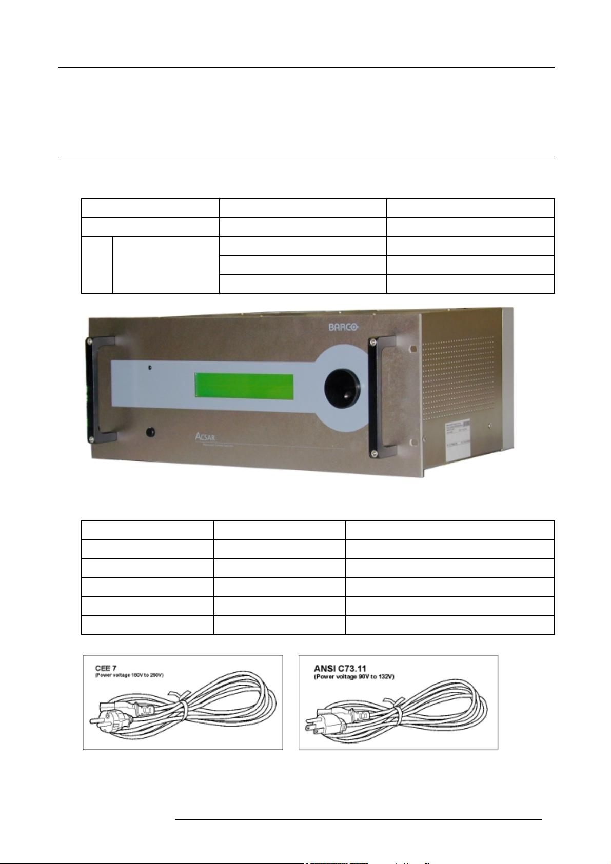
ACSAR
Inclusive modules
Image 2-1
ACSAR
Supplied accessories
R9806700
R763597
R763753 Output Interface
R7630355 Remote Control
Alternative Content Switcher & Router
DVI Output
Item Art. No Description
Power Cord R326103 (image 2-2) CEE C13 2M5
Power Cord R3261115 (image 2-3) NEM5C13 2M
Cable DVI 24P24P Z34875232 (image 2-7) Connection cable DVI
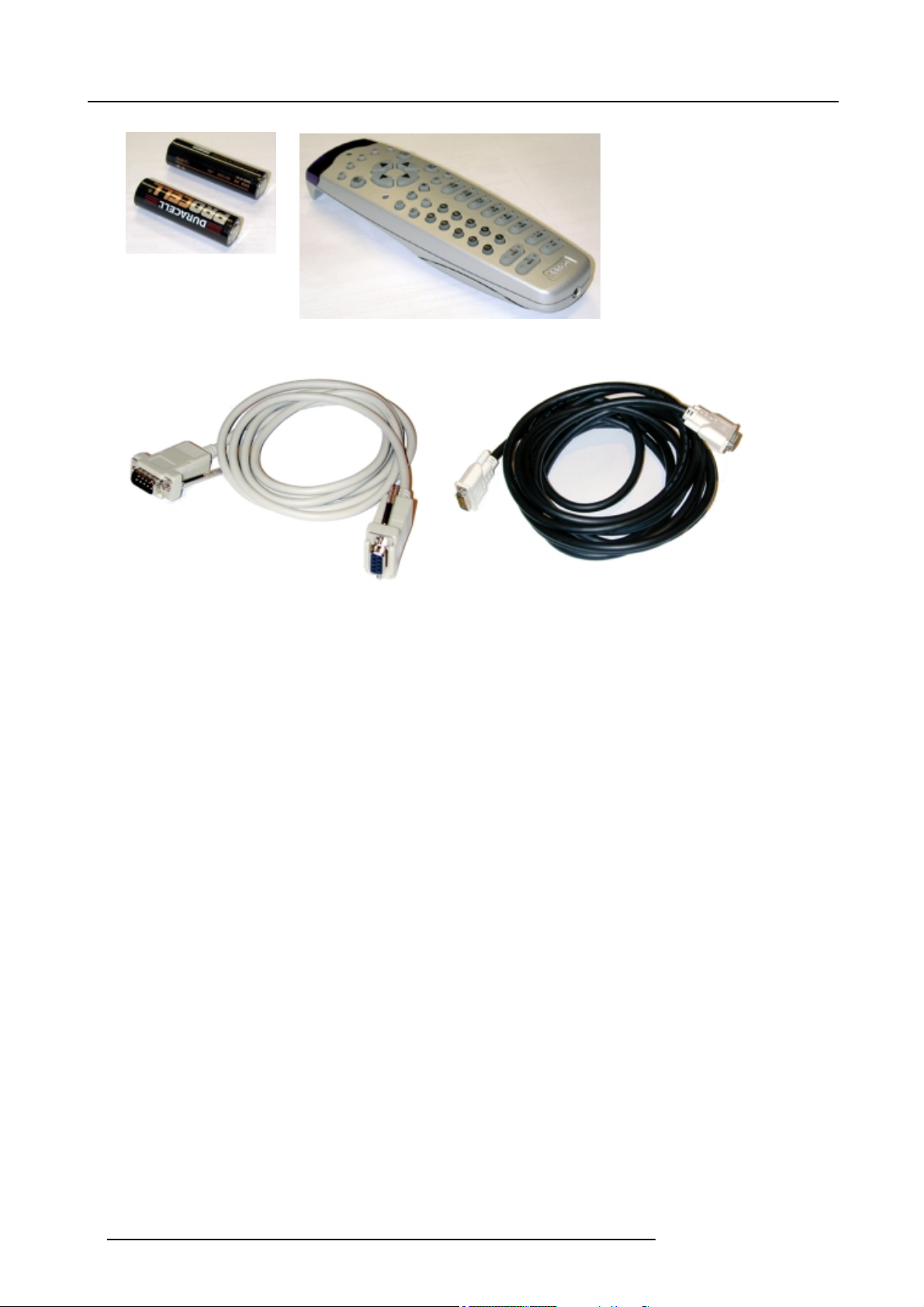
Remote Control RC5 R7630355 (image 2-5) Infra Red remote control RC5
Batteries
Image 2-2
Power cord CEE
R5976519 ACSAR 12122002 7
G100810 (image 2-4) 2x AA size batteries for Remote Control
Image 2-3
Power cord ANSI
Page 12
2. ACSAR package contents
Image 2-4
AA size batteries
Image 2-5
Remote control RC5
Image 2-6
RS232 cable
Image 2-7
DVI cable
8 R5976519 ACSAR 12122002
Page 13

3. ACSAR Concept
3. ACSAR CONCEPT
Overview
• Alternative Content Switcher and Router
• ACSAR on Module level
3.1 Alternative Content Switcher and Router
Modular convenience
• Quick and easy configuration
• For the permanent connection of any combination of fixed inputs plus the connections of temporary sources.
• Compatible with almost any digital or analog input.
Convenient image Formatting, Switching and Routing
Advanced Barco pixel map processing (PMP) for the scaling and reformatting of any standard or HD video or PC input to the native
1280x1024 format of the D-Cine digital head.
Simple operation
With a wide range of operating features, a choice of a simple front panel or remote control via the D-Cine LCD touch panel or Barco’s
RC5 infra red controller, plus a preview monitor output for cueing and seamless switching of selected video inputs.
3.2 ACSAR on Module level
Video Input modules
The ACSAR allows the insertion of 8 hot plug–in Video modules.
Module Description Order Reference
RGB Analog Sync H & V
Sync Composite
Sync on Green
SDI Serial Digital Input
HD SDI High Definition SDI
Analog Video Composite Video
S-Video with digital decoder
DVI
Digital Versatile Interface
In- / Output modules (parts of the unit)
Module Description
DVI Output Digital Versatile Interface standard output linked to the DVI
2x D9 RS 232 connectors In/out RS232 communication
input of the projector head.
R9841040
R9841120
R9841110
R9841030
R9841070
Single board PC (IP Address) Via an option
management
R5976519 ACSAR 12122002 9
al single board computer with remote network
Page 14
3. ACSAR Concept
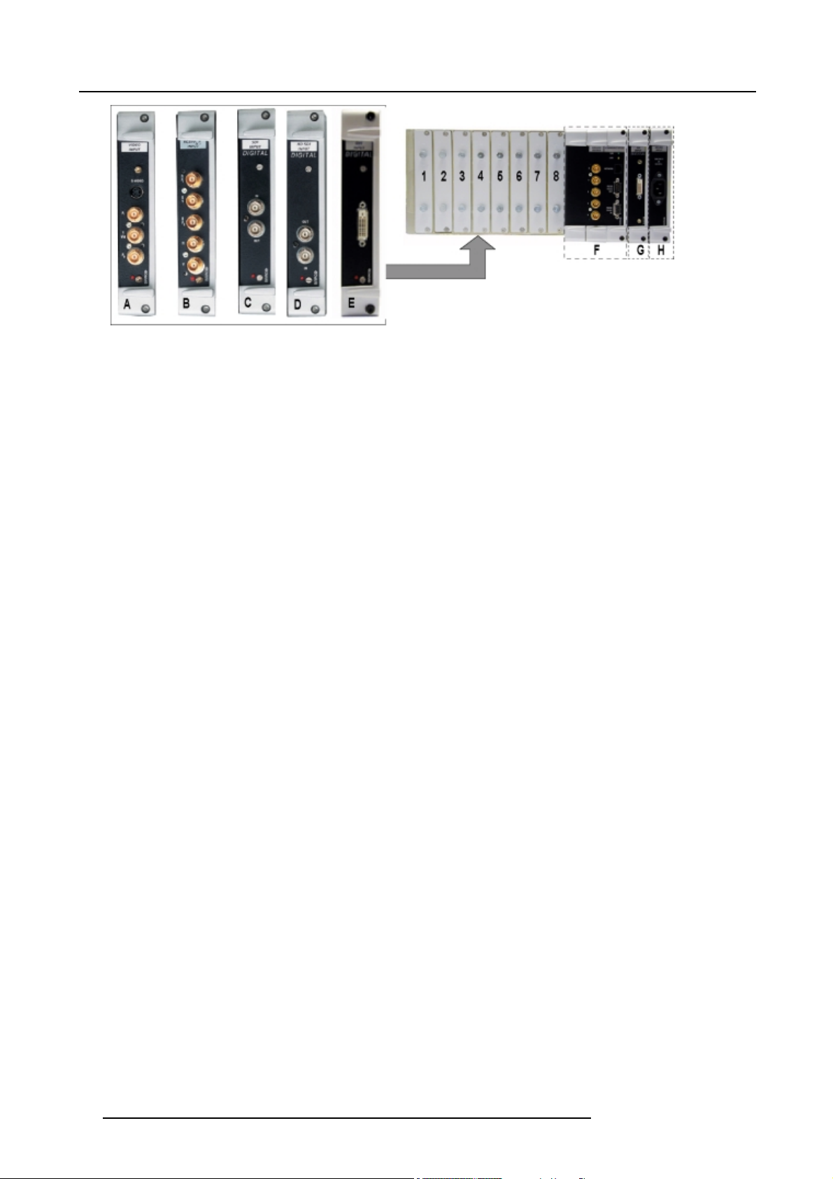
Image 3-1
A Video/S-Video/Component input module
B RGB-HV input module
C SDI Input module
D HD SDI input module
E DVI input module
F RGB-HV Out & RS 232 communication In/Out
G DVI Output
H Power input module
1-8 Input slots
10
R5976519 ACSAR 12122002
Page 15
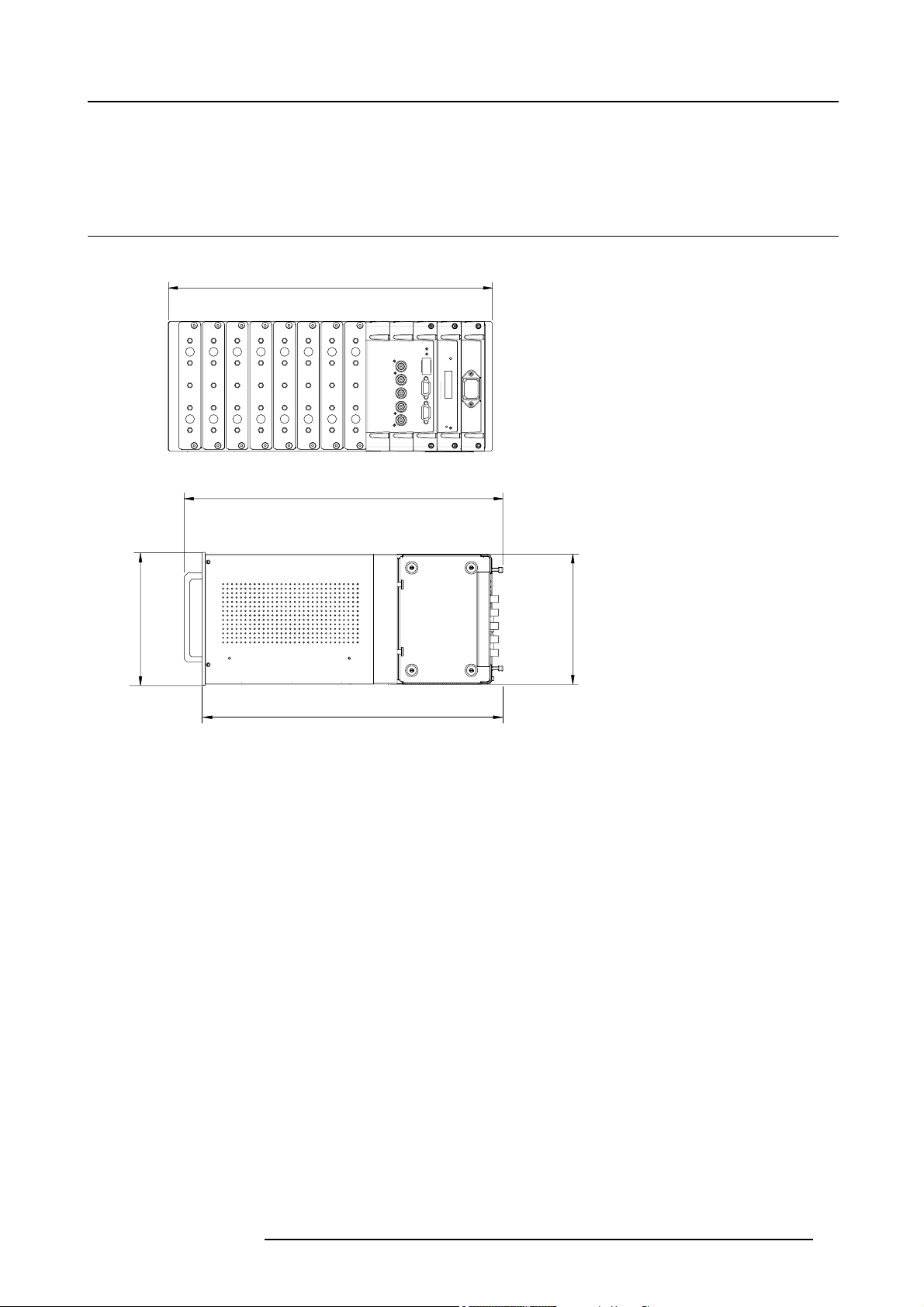
4. DIMENSIONS OF THE ACSAR
6
.
8
5
I
n
c
h
e
s
4.1 ACSAR
Outside dimensions
434 mm
17.09 Inches
456 mm
17.95 Inches
4. Dimensions of the ACSAR
m
s
m
e
h
7
c
7
n
1
I
7
9
.
6
416 mm
Image 4-1
Outside dimensions
16.38 Inches
Rack specification
The ACSAR fits into a 19” rack (w) x 4u (h) x 400 (d) mm with input modules.
m
m
4
7
1
R5976519 ACSAR 12122002
11
Page 16

4. Dimensions of the ACSAR
12 R5976519 ACSAR 12122002
Page 17
5. Mounting the ACSAR into the Console
5. MOUNTING THE ACSAR INTO THE CONSOLE
Before proceeding to the mechanical installation of the ACSAR unit, resulting in opening the console, be sure
the console has been switched off totally (Refer to the installation manual for switching off the console).
5.1 Installation of the ACSAR
Necessary tools
Cross point screw driver of 5 mm.
How to install the ACSAR unit in the console
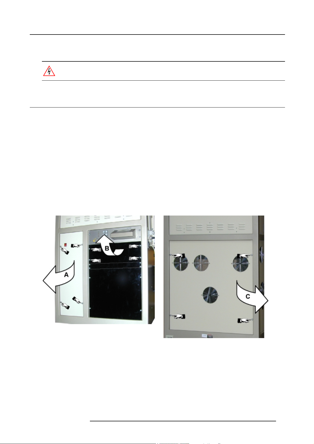
1. To be able to install the ACSAR unit, remove the following covers on the console:
- Dummy cover plate (B): remove the 4 screws securing plate to console and remove the cover. Retain screws for the fixation
of the ACSAR unit. (image 5-1)
- Side cover with power switch (A): remove the 4 screws securing plate to console. Take the cover out of console frame and
put it beside the console (cover displacement limited by the ground cable and the power switch connection). Retain screws
for reinstallation of the cover (image 5-1).
- Main power cover (C): remove the 4 screws securing plate to console and remove the cover (cover displacement limited by
the ground cable). Retain screws for reinstallation of the cover. (image 5-2)
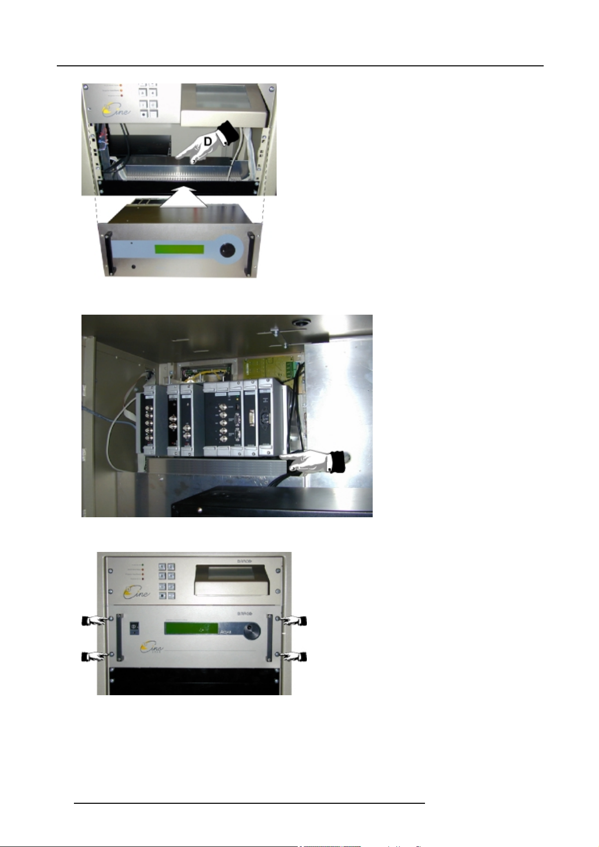
2. Carefully slide the ACSAR unit on its place in the console, taking care that the bottom of the unit rest on the provided support
(D). (image 5-3, image 5-4)
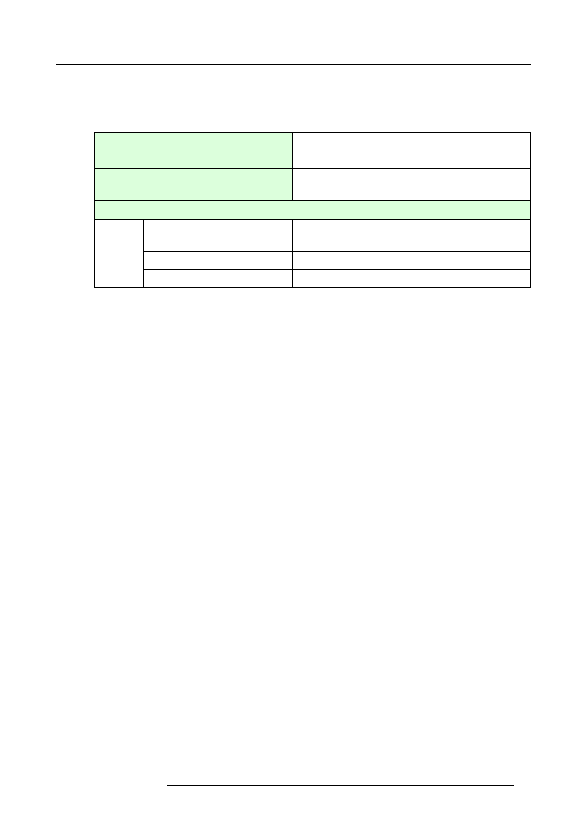
3. Secure the position of the unit with the 4 retained screws. (image 5-5)
4. Continue with the electrical connections of ACSAR power, communication and DVI.
Image 5-1
Cover removal left side console
A Side cover with power switch
B Dummy cover plate
R5976519 ACSAR 12122002 13
Image 5-2
Cover removal right side console
Page 18
5. Mounting the ACSAR into the Console
Image 5-3
Insertion of the ACSAR into the console
Image 5-4
Rear view ACSAR unit on support
Image 5-5
Securing the ACSAR onto the console frame
14 R5976519 ACSAR 12122002
Page 19
5.2 Connecting the ACSAR to console
Which connections have to be made:
• Power connection.
5. Mounting the ACSAR into the Console
AC Power Voltage
AC Power Current 1A/50–60Hz
Main Fuses
Power Consumption
Normal operation mode 78 W
Standby mode
Economic standby mode 4W
• RS 232 communication between ACSAR, Touch panel and Digital Head.
• DVI link between DVI output ACSAR and DVI input Digital Head.
Auto Range 100 – 240V
Standby Power Supply: T 2AH/250V
Main Power Supply: F 4A L 250V
Depending on input configuration
8W
Necessary parts
A RS232 communication, a DVI link and a power cable (type CEE C13), added to the ACSAR unit.
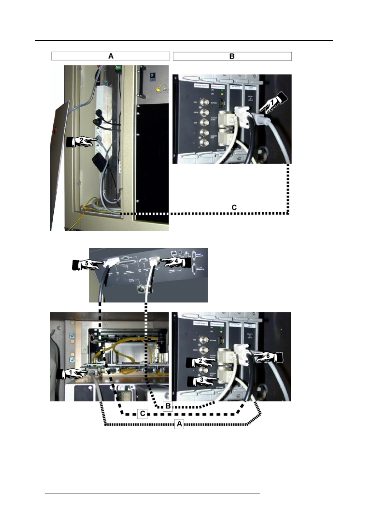
How to connect the ACSAR unit to the console
1. Plug the female connector (1) of the power cord (CEE C13 2M5) (C) into the male connector on the power input board of the
ACSAR. Make sure that the power cord plug is firmly inserted into the AC socket. (image 5-6)
2. Plug the male connector (2) into a free
3. Interrupt, in the exiting connection, the control link between Touch panel and Digital Head by pulling out D-9 plug (1) on Touch
panel interface board and reinserting it in the RS232 OUT socket (2) on the communication module of the ACSAR (Link B).
(image 5-7)
4. Install communication link (A) between RS232 IN (3) on the communication module of the ACSAR and the interface board (1) of
the Touch panel, using the added D9-D9 serial data cable (image 5-7).
5. Install the DVI link (C) between DVI Output (6) on the communication module of the ACSAR and DVI Input (5) on the input panel
of the Digital Head, using the added DVI cable (image 5-7).
Note: The DVI cable has to be routed through the cable hole in front of the console.
6. Reinstall the removed covers before operation the D-Cine projector.
AC socket on the outlet strip in the console.
R5976519 ACSAR 12122002
15
Page 20
5. Mounting the ACSAR into the Console
Image 5-6
Image 5-7
Installation of the DVI link and the RS232 communication
16 R5976519 ACSAR 12122002
Page 21
6. Signal Connections
6. SIGNAL CONNECTIONS
Overview
• Connections for Preview and Communications
• Connection to Video Equipment
6.1 Connections for Preview and Communications
6.1.1 Connections for Preview
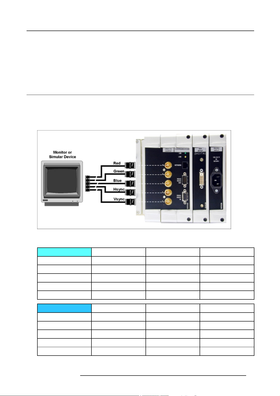
Connections for preview Monitors
The 5 BNC’s on the output module carry the RGB Analog Video output signal with Separate Sync (H & V) for preview monitors
matching the output timings. The supplied RGB Analog video signal has the same resolution as the digital video output.
Image 6-1
Preview Monitor connection
Analog Output Timings
Vertic al Sync
Period 20 msec 16.7 msec 16.7 msec
Sync Width
Back Porch 63.7 µsec 63.7 µsec 63.7 µsec
Front Porch 3.6 msec 237 msec 237 msec
Active Signal
Horizontal Sync
Period 15.9 µsec 15.9 µsec 15.9 µsec
Sync Width
Back Porch 2.48 µsec 2.48 µsec 2.48 µsec
Front Porch 240 µsec 240 nsec 240 nsec
Active Signal
Pal
63.7 µsec 63.7 µsec 63.7 µsec
16.3 msec 16.3 msec 16.3 msec
Pal
0.40 µsec 0.4 µsec 0.4 µsec
12.8 µsec 12.8 µsec 12.8 µsec
NTSC PC/no signal
NTSC PC/no signal
R5976519 ACSAR 12122002 17
Page 22
6. Signal Connections
• Back Porch = from rising edge of Sync to begin of active video.
• Front Porch = from end of active video to falling edge of Sync.
6.1.2 Connections or Communication
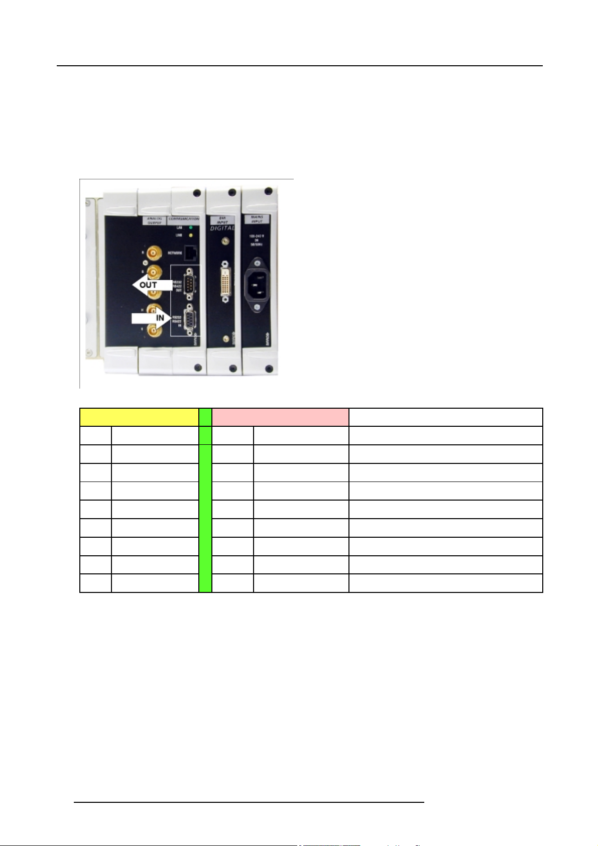
Purpose
The two D9 connectors RS422/RS232 In- and Output are defined as open standard for Communication with other Devices such as
Control Panels (AMX, Creston
TM
) and Audio Switchers).
Image 6-2
RS232 Communication
RS232/422 IN RS232/422 OUT
Pin Ref. Pin Ref. Description
1
6
2 RXD-_IN 2
3 TXD-_IN 3
8 CTS_IN Clear To Send
4 TXD+/DTR_IN 4 TXD+/DTR_OUT Transmit Data/Data Terminal Ready
9 RI_IN Ring Indicator
5/10 GROUND 5/10 GROUND GROUND
DCD_IN Data Carry Detect
RXD+/DSR_IN
6
RXD+/DSR_OUT Read Data/Data Set Ready
RXD-_OUT
TXD-_OUT
Read Data
Transmit Data
6.1.3 Network Connections
Purpose
Controlling and monitoring of the ACSAR settings. Remote diagnostics to detect potential errors.
18
R5976519 ACSAR 12122002
Page 23
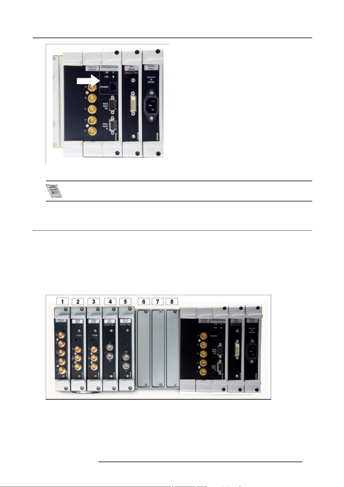
Image 6-3
Network connection
6. Signal Connections
Actually, this connection is not supported internally (Development status).
6.2 Connection to Video Equipment
Overview
• Input Connection per Module
• Installation of an Input module
General
The ACSAR is a powerful scaler and router designed to convert any incoming signal to the DVI digital output of the unit itself, linked
on its turn to the DVI input of the D-Cine projection head. It can be equipped with up to 8 digital and analog input modules which
enable it to process all types of video, component video, RGB, SDI, HD-SDI, DVI and any future video standardizing.
Image 6-4
Input modules overview
1 RGB / YPrPb Input module
2 Video Input module
3 Video Input module
4 SDI Input module
5 HD SDI Input module
6-8 Free input slots (can be filled up with one of the above modules)
R5976519 ACSAR 12122002
19
Page 24
6. Signal Connections
6.2.1 Input Connection per Module
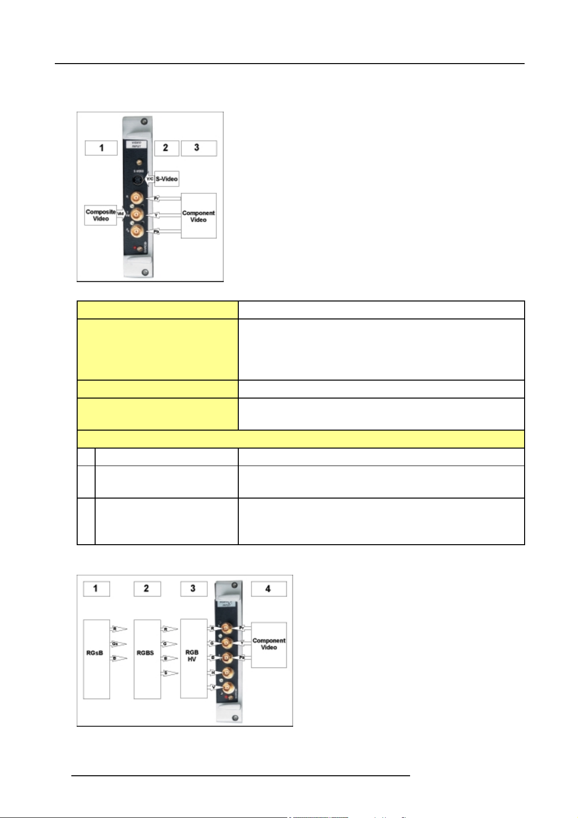
Video Input module
Image 6-5
Video Input module
Input mode
Decoder
Comb Filter Adaptive 2/4 line Comb Filter for two dimensional Y/C separation
Features - Built in Copy-Protection detection
Input signal level
Video Input Mode
S-Video Input Mode Y+Synchro 1.0Vpp
Component Input Mode Y+Synchro 1.0Vpp
Signal format (1), (2) or (3) selectable
Digital Multistandard Decoder, running at twice the oversampling rate (27 MHz).
-PAL,PALM,PALN
- NTSC, NTSC M, NTSC Japan, NTSC 4.43
- SECAM
- Automatic Gain and Clamping control
Composite Video signal 1.0Vpp
C burst level 0.286Vpp
Pr
Pb
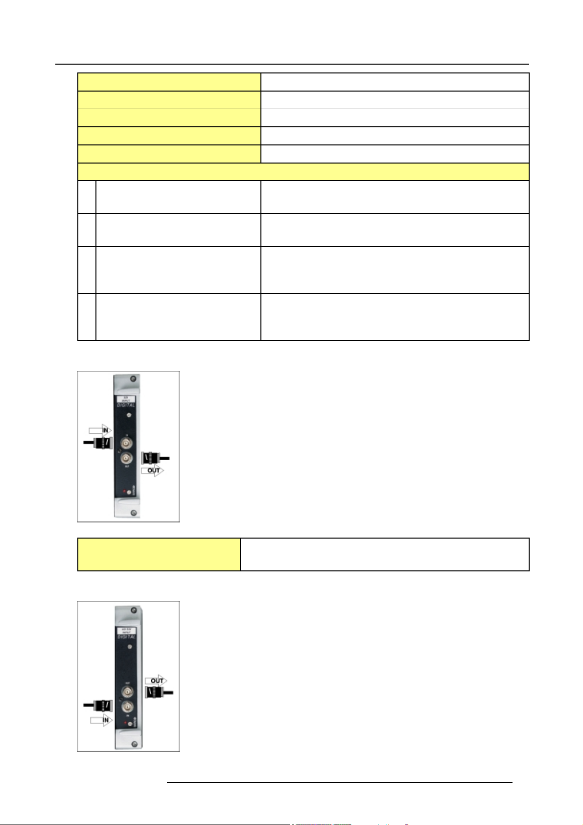
RGB/HV/YPrPb Input
Image 6-6
RGB/HV Input module
20 R5976519 ACSAR 12122002
Page 25
6. Signal Connections
Input mode Signal format (1), (2), (3) or (4) selectable on the GUI menu
Bandwidth
Signal support Supports signals up to 205 MHz Pixel clock (1600 x 1200 @ 75 Hz)
Sync Detection Automatic Sync detection for: RGBHV, RGBS and RGsB.
Sync Polarity Automatic Sync Polarity detection
Input signal level
RGsB Input Mode RGB signal: 0.7Vpp
RGBS Input Mode RGB signal: 0.7Vpp
RGB/HV Input Mode RGB signal: 0.7Vpp
Component Input Mode Y+Synchro: 1.0Vpp
500 MHz RGB Analog Bandwidth convertor
Composite Video Sync on G: 1Vpp
Composite Video Sync on H: 1Vpp
Hs Sync signal: 0.7Vpp
Vs Sync signal: 0.7Vpp
Pr
Pb
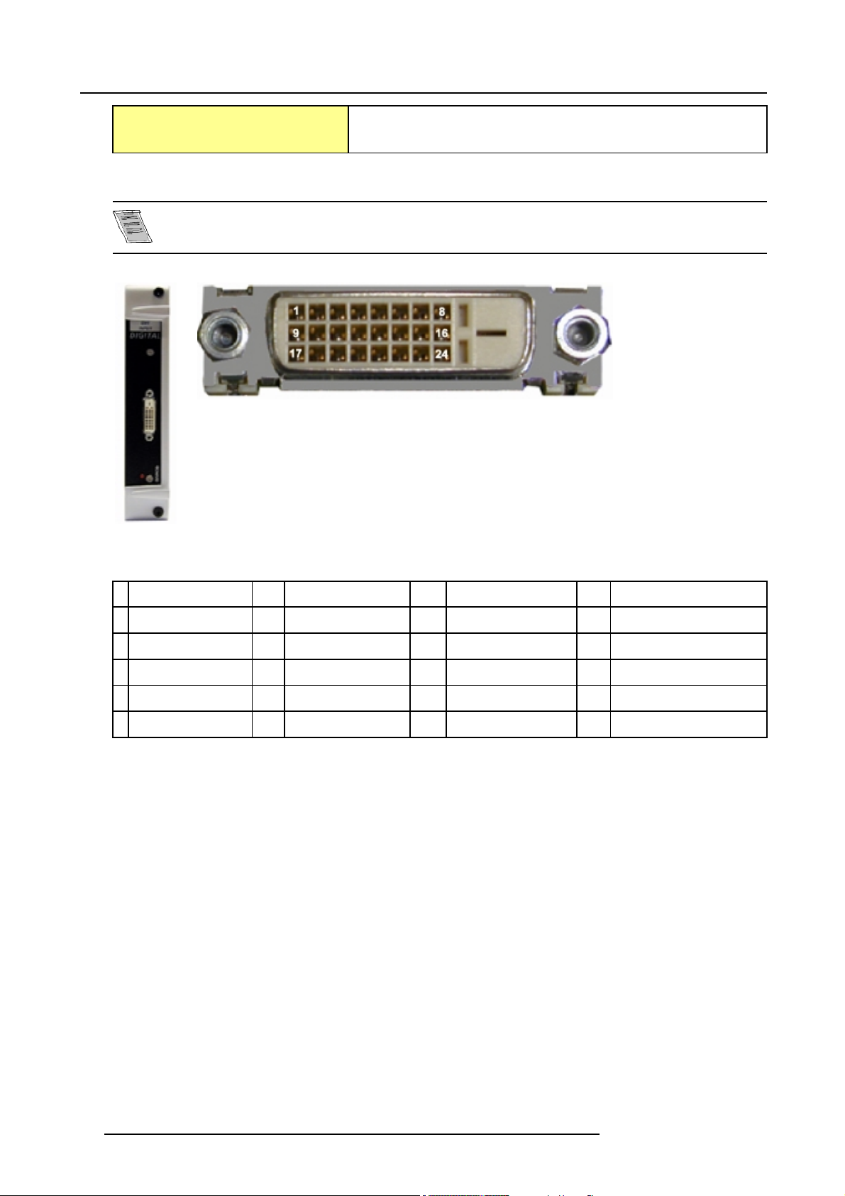
SDI Input
Image 6-7
Features
- Loop through SDI Input (SDI in/SDI out)
- For DVD players and other Video equipment with SDI out.
HD SDI Input
Image 6-8
R5976519 ACSAR 12122002 21
Page 26
6. Signal Connections
Features - Loop through HD-SDI Input (HD-SDI in/HD-SDI out)
- For HD-DVD players and other HD Video equipment with HD-SDI out.
Digital Visual Interface Input (DVI)
DVI: Digital Visual Interface is a display interface developed in repose to the proliferation of digital flat panels
displays. It uses a high speed serial interface with TMDS (Transition Minimized differential signalling) to send
data to the display. DVI can be single or dual link.
Image 6-10
Image 6-9
DVI input mo
with DVI-D type
connect
1 RX2-
2 RX2+ 8
3
4
5
6
dule
or
RX2 Shield
TMDS DATA 4-
TMDS DATA 4+
SCL_PC
7
SDA_PC 13 TMDS DATA 3- 19 RX0 Shield
nc
9 RX1- 15
14 +5V Host 20 TMDS DATA 5-
GND
21
10 RX1+ 16 Hot Plug Detect 22
11
RX1 Shield
12
TMDS DATA 3-
17 RX0- 23
18 RX0+ 24
6.2.2 Installation of an Input module
How to install an Input module
1. Has the new input module to be inserted in a free slot?
If yes, go to step 2
If no, go to step 3
2. Take away the dummy plate by removing the two securing screws (A) and continue with step 5. (image 6-11)
3. Unlock the module by loosening the rod screws (A). (image 6-12)
4. Carefully pull out the module (image 6-12).
5. Match the module plug with the slot connector and push the plug into the connector. (image 6-13)
6. Secure the module by tightening the rod screws (A)(image 6-13).
TMDS DATA 5+
TMDS Clock Shield
RXC+
RXC-
22
R5976519 ACSAR 12122002
Page 27
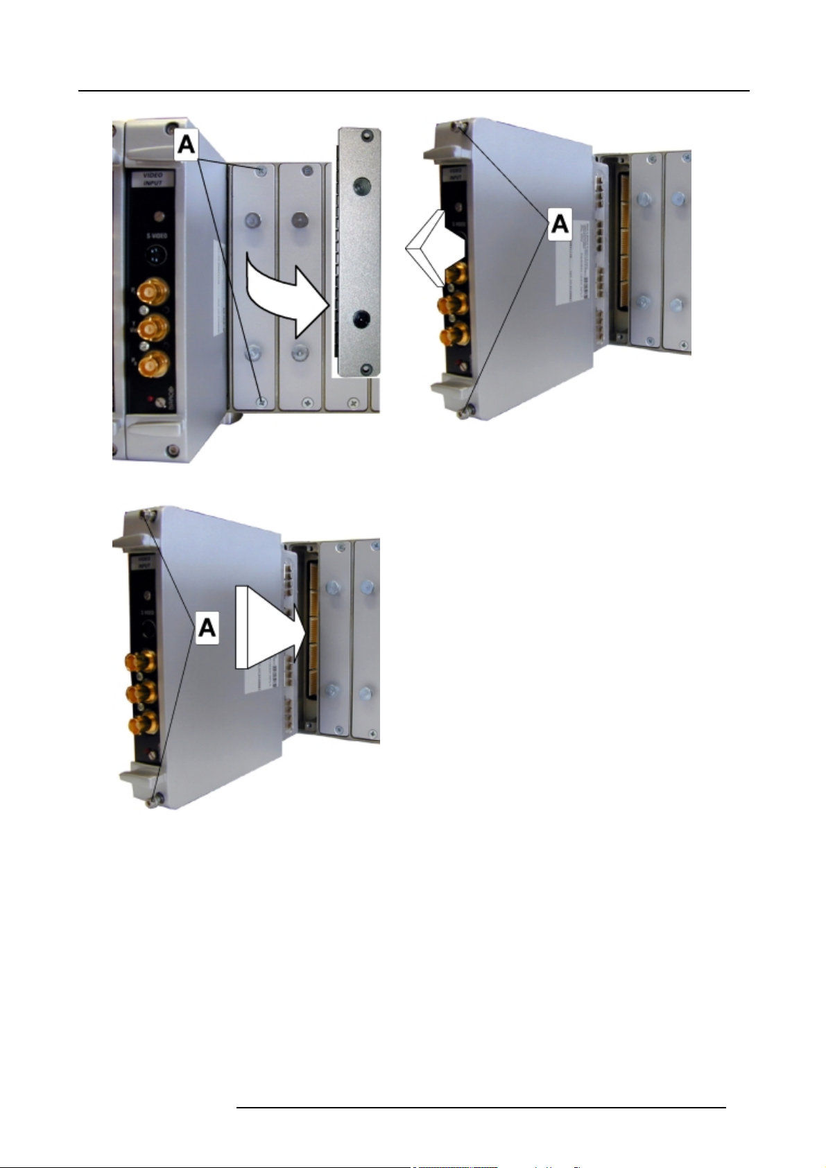
Image 6-11
6. Signal Connections
Image 6-12
Image 6-13
R5976519 ACSAR 12122002 23
Page 28

6. Signal Connections
24 R5976519 ACSAR 12122002
Page 29
7. LOCATIONS OF CONTROLS
Overview
•OntheACSAR
• On the Remote Control
7.1 On the ACSAR
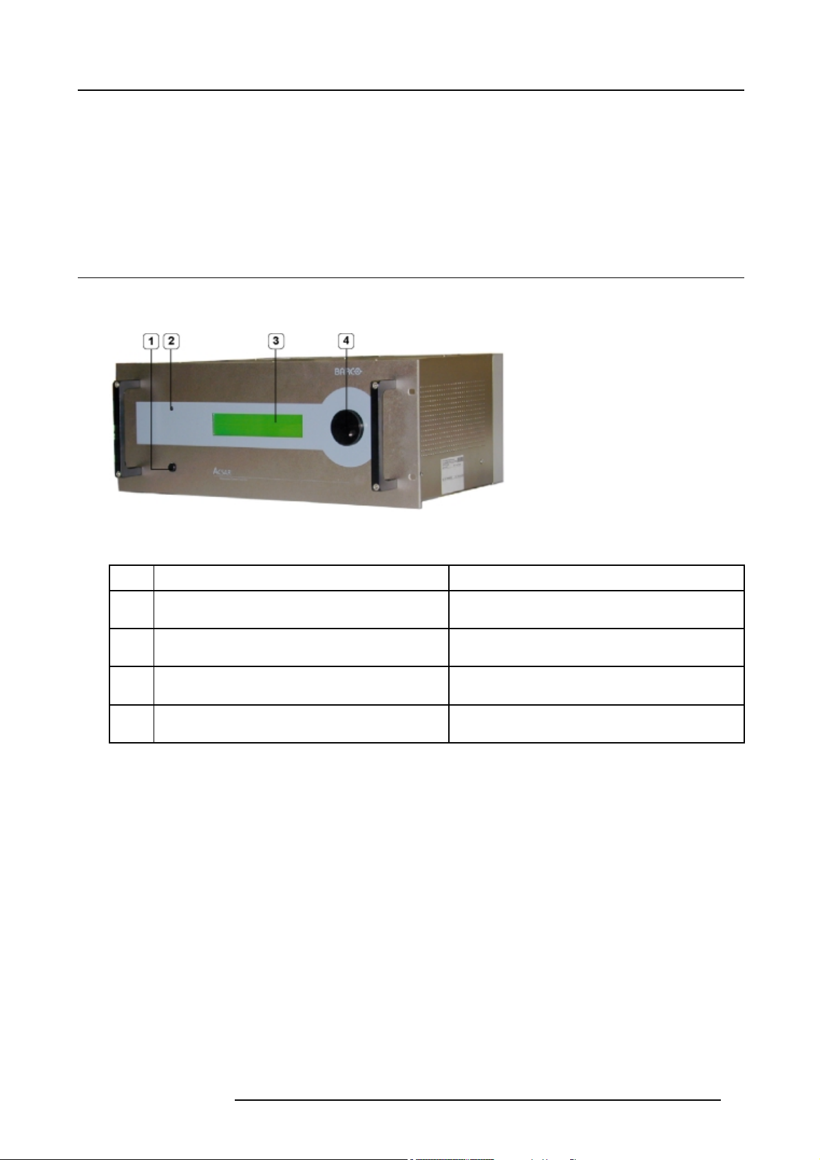
Front view
All controls for the ACSAR are provided on the front side.
7. Locations of Controls
Image 7-1
Location controls ACSA R
Controls function description
Ref.
1 Push button main power switch
2
3 Black Dot Matrix display with green LED backlighting
4 Start up and Random access adjustment mode selection
Function Description
Infra Red Receiver Infra Red reception diode for the IR signals from the IR
knob
Button pressed, switches the ACSAR in the standby
mode.
transmitter.
This display indicates the status of the ACSAR and als
the items when navigating through the different menu’s.
All source parameters and picture tuning are setup in
the adjustment mode.
o
R5976519 ACSAR 12122002 25
Page 30
7. Locations of Controls
7.2 On the Remote Control
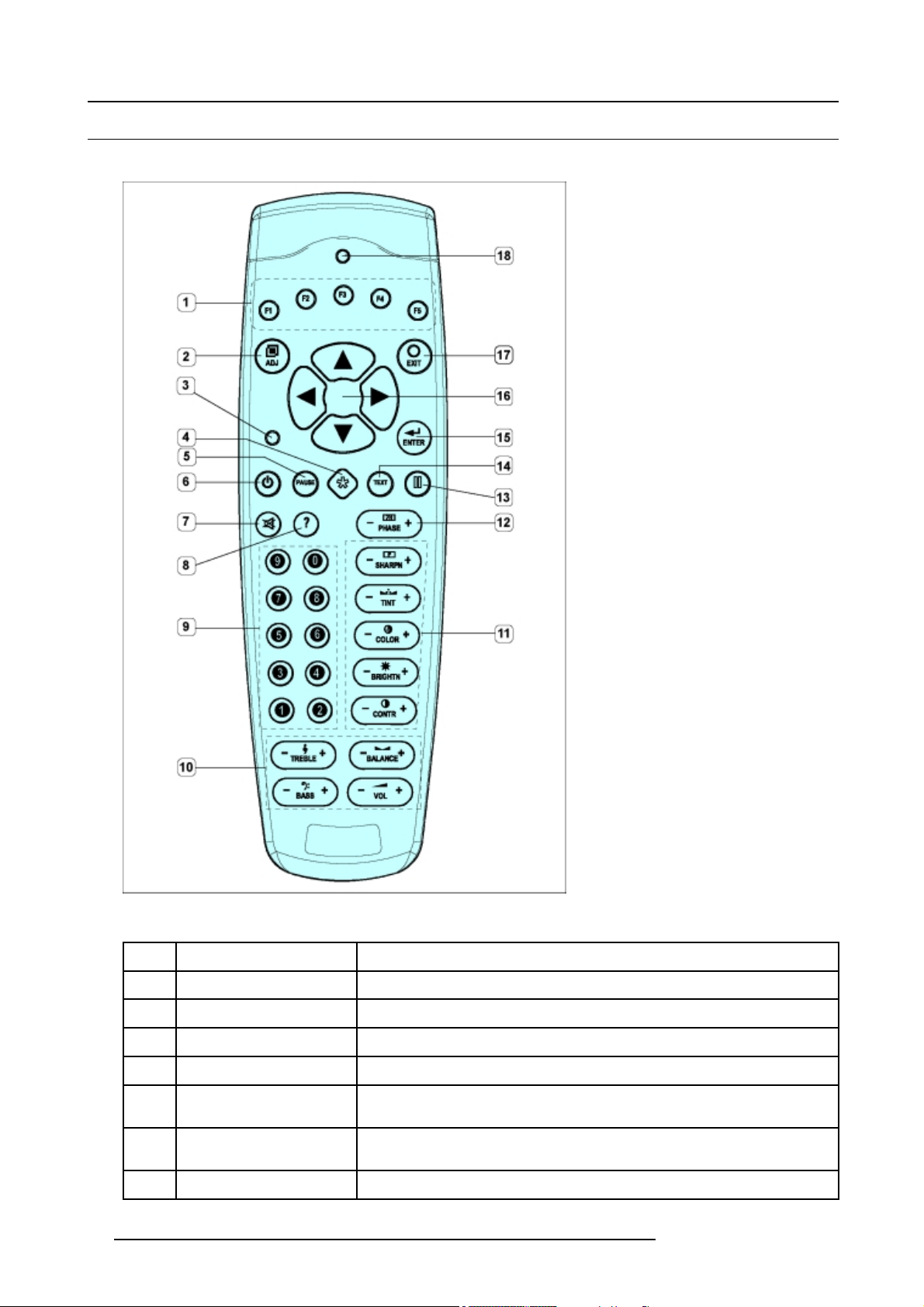
Top s i d e
Image 7-2
Controls function description
Ref.
1 Function keys
2
3 Address key
4 Selection key
5
6 Standby key From a powered up ACSAR, pressing StdBy, switches the ACSAR into operation or
7 MUTE
26 R5976519 ACSAR 12122002
Function Description
User’s programmable keys with functions for direct access.
ADJ (Adjust key)
PAU SE k ey To stop projection for a short time, press ’PAUSE’. The image projection is
Toggle key to enter or to exit the adjustment mode.
To match the address of the RCU with the ACSAR (number between 0 and 9).
no use
interrupted but full power is retained for immediate restarting image projection.
back into standby mode.
no use
Page 31

Ref. Function Description
8
9 Digit buttons Allow direct input selection and address setting
10 Audio controls
11 Picture controls Allow to optimize the picture reproduction.
12 PHASE Allow to remove image instability
13 FREEZE Press to freeze the image
?
no use
no use
7. Locations of Controls
14 TEXT
15 ENTER Press to start the adjustment mode, confirm an adjustment or selection in the
16 Cursor keys Allow menu selections in the adjustment mode.
17 EXIT Press to leave the adjustment mode via scrolling upwards in the menu structure.
18
RC operation indication Lights up when a key on the remote control is pressed (Visual indication of remote
Press to remove all on screen display when adjusting picture (Handy when adjusting
picture during a meeting). Press key again for re-activation.
adjustment mode.
control operation – Battery check).
R5976519 ACSAR 12122002 27
Page 32

7. Locations of Controls
28 R5976519 ACSAR 12122002
Page 33

8. Operating the Remote Control
8. OPERATING THE REMOTE CONTROL
Overview
• Battery Insertion in the Remote Control
• Operating the Remote Control
• Address setting for the Remote Control
8.1 Battery Insertion in the Remote Control
– Insert batteries so that the plus (+) and minus (-) sides are aligned according to the markings in the battery
case.
– Do not mix new batteries with used ones.
– The voltage of batteries may differ even if they are the same shape. Please do not mix different kinds of
batteries.
– When not using the remote control unit for a long period of time (1 month of more), remove the batteries
from the remote control unit to prevent leaking of battery fluid. If battery liquid has leaked, thoroughly wipe
the inside of the case until all liquid is removed, an then insert new ba
- Do not charge, short, disassemble or throw the provided batteries in a fire.
tteries.
When disposing of used batteries, please comply with governmental regulations or environmental public instruction’s rules that apply in your country.
Where to find the batteries
The batteries are not placed in the remote control to avoid remote control operation in its package, resulting in a shorter battery life
time.
The batteries are packed separately and added to the package of the remote control.
How to install the batteries
1. Push the cover tab (A) with the fingernail a little backwards and pull upwards the cover top (B). (image 8-1)
2. Slide the cover forwards to remove. (image 8-2)
3. Push the battery body towards the spring and lift it up to remove. (image 8-3)
4. Insert two AA size batteries, making sure the polarities match the + and – marks inside the battery compartment (image 8-3).
5. Insert the lower tab of the battery cover in the gap at the b
(image 8-3).
ottom of the remote control, and press the cover until it clicks in place
Image 8-2
Battery cover removal
Image 8-1
Battery cover unlock
R5976519 ACSAR 12122002 29
Page 34

8. Operating the Remote Control
Image 8-3
Battery removal
8.2 Operating the Remote Control
Remote Control operation
This remote control includes a battery powered infrared transmitter which allows the user to control the ACSAR remotely via its own
built-in infrared receiver.
If backlight and RC operation indicator lights up too long or continuously, batteries need to be replaced.
Image 8-4
Remote control operation angle
When operating the remote control unit, point it at the remote sensor, located on the front side of the ACSAR. The remote control
unit is operable up to 9 m from the unit and within a 45 angle on each side of the sensor.
When a key on the remote control is pressed, backlight is activated automatically. That allows the user to operate the remote control
in a dark room. Backlight is turned off automatically a few seconds after the last key activation.
Remote control operation’s difficulties
• The remote control unit may not operate if there are objects placed between it and the display.
• Operational distances will gradually become shorter as the batteries begin to wear out, replace weak batteries with new ones
as soon as possible.
30
R5976519 ACSAR 12122002
Page 35

8. Operating the Remote Control
8.3 Address setting for the Remote Control
How to set the Remote Control address
1. Point the Remote Control to the module you desire to know the address and press the address key (recessed key).
On-screen and in the graphical display appears the number of the address. Now proceed to program the address in the Remote
Control.
2. Again, press the ADDRESS key on the Remote Control. (image 8-5)
3. Press the digit key, corresponding with the desired address (between 0 and 9), WITHIN 5 SECONDS after the key has been
pressed. (image 8-6)
The commands from the Remote Control are sent with the stored address.
Image 8-5
Address key
Image 8-6
Digit keys
R5976519 ACSAR 12122002 31
Page 36

8. Operating the Remote Control
32 R5976519 ACSAR 12122002
Page 37

9. STARTING UP THE ACSAR
Overview
• StartingUptheACSAR
• Powering Down the ACSAR
9.1 Starting Up the ACSAR
HowStartingUptheACSAR
Starting up the ACSAR, after its own power switch button (1) has been pressed, can be performed by:
9. Starting up the ACSAR
Image 9-1
Starting up the ACSAR
• Pressing the selection wheel on the ACSAR (2) in the standby mode (Item POWER is pointed in the graphical display).
• Pressing STBY button on the Remote Control (3).
• Pressing POWER in the ACSAR menu (4), displayed on the touch panel when consecutively HOME and ACSAR touch button
have been touched.
The ACSAR always starts up on the last selected
Graphical Display
"video625.c05"
SELECT
6. VIDEO [VIDEO]
Image 9-2
SOURCE 6 [H:15 kHz V:50 Hz]
source, whose file be displayed in the graphical display.
9.2 Powering Down the ACSAR
Intro Powering Down
Powering down the ACSAR means switching the unit from operation mode into standby mode. To reduce power dissipation, if the
unit stays unused for a period and quick restart is required, the unit can be switched into the Economic mode.
Switching the unit into the standby mode can be performed as follows (image 9-1):
• Rotate the selection wheel (2) until item STBY appears in the graphical display and press selection wheel (2) to confirm.
• Press the STBY button on the Remote Control for a few seconds (3).
• Press POWER in the ACSAR menu (4) on the touch panel.
• From the Standby mode menu, rotate the selection wheel (2) until item ECONOMIC appears in the graphical display and press
selection wheel (2) to confirm.
R5976519 ACSAR 12122002
33
Page 38

9. Starting up the ACSAR
Switching the ACSAR into the Economic mode is only possible with the selection wheel.
Switching to Standby/Economic with selection wheel
1. Rotate selection wheel until item STANDBY appears in the select menu. (image 9-3)
2. Press the selection wheel to confirm.
The unit switches into the standby mode and the standby menu appears in the graphical display. (image 9-4)
3. Rotate the selection wheel until item ECONOMIC is pointed and press wheel to confirm.
The unit switches into the economic mode which results in a lower dissipation of the unit inclusive turning off backlighting of the
graphical display. (image 9-5)
Press selection wheel again to return to Standby menu (image 9-4).
Graphical Display
"video625.c05"
SELECT
STANDBY
Image 9-3
Select menu
SOURCE 6 [H:15 kHz V:50 Hz]
Graphical Display
STANDBY
MENU
>POWER
ECONOMIC
Image 9-4
Standby menu
Graphical Display
ECONOMIC
Image 9-5
Economic mode
Switching to Standby with the Remote Control
1. Press the STBY button on the Remote Control for a few second
The unit switches into the standby mode and the standby menu appears in the graphical display (image 9-4).
2. Switching to the Economic mode, use selection wheel on ACSAR .
Switching to Standby using Touch Panel
1. Press POWER
The unit switches into the standby mode and the standby menu appears in the graphical display (image 9-4).
2. Switching to the Economic mode, use selection wheel on ACSAR .
in the ACSAR menu again on the touch panel.
34
R5976519 ACSAR 12122002
Page 39

10. Way of Scrolling through the Menus
10. WAY OF SCROLLING THROUGH THE MENUS
10.1 Way of displaying the Menus
How the menus are displayed?
The different adjustment items are structured in main and sub menus. On the ACSAR itself, the menus
graphical display (display item per item) whereas on the projected picture a menu box appears, containing all menu items.
Main Menu Display
are displayed on a 4 line
ACSAR
Image 10-1
View main menu in Graphical display and OSD
Sub Menu D isplay
ACSAR
ADJUSTMENT MODE
RANDOM ACCE SS
>INSTALLATION
SERVICE
RE TURN
INPUT SLOTS
3. VIDEO [VIDEO]
ADJUSTMENT MODE
Select a path from
RANDOM ACCE SS
INSTALLATION
Select with
then <ENTER>
<EXIT> to return
INPUT SLOTS
1 NO MODULE
2 NO MODULE
3 VIDEO [VIDEO]
4 NO MODULE
5 NO MODULE
6 NO MODULE
7 RGB-YUV [RGB]
8 NO MODULE
Select with
then <ENTER>
<EXIT> to return
OSD
below
SERVICE
Source 6
− or /
OSD
− or /
Image 10-2
View sub menu in Graphical display and OSD
10.2 Way of scrolling through the menus
How to scroll through the menus?
Scrolling through the menus can be executed using the selection wheel on the ACSAR or the cursor keys on the Remote Control.
R5976519 ACSAR 12122002
35
Page 40

10. Way of Scrolling through the Menus
Selection wheel on ACSAR
Rotating left or right
Main menu
The menu items rotate in front of the pointer in the graphical display. Pressing
the selection wheel confirms the pointed selection.
Sub menu The sub items rotate one at the time below the sub menu title in the graphical
display. Pressing the selection wheel confirms this specific sub item.
Pressing
To r e tu r n
Confirmation of the selection
Select item ’RETURN’ and press selection wheel
Remote control
↑ or ↓ cursor key pressed Runs through the items of the menu clockwise or counterclockwise. The selected
item is highlighted
ENTER pressed Confirmation of the selection
EXIT pressed Returns one level back in the menu structure.
Main Menu Display
ADJUSTMENT MODE
Select a path from
RANDOM ACCE SS
INSTALLATION
OSD
below
SERVICE
ACSAR
ADJUSTMENT MODE
RANDOM ACCE SS
>INSTALLATION
SERVICE
RE TURN
ADJUSTMENT MODE
RANDOM ACCE SS
>INSTALLATION
SERVICE
RE TURN
Image 10-3
Scrolling through the main menus
ADJ
PAUSE
90
Source 6
then <ENTER>
− or /
Select with
EXIT
ENTER
TEXT
PHASE
SHARPN
<EXIT> to return
36 R5976519 ACSAR 12122002
Page 41

Sub Menu D isplay
10. Way of Scrolling through the Menus
ACSAR
INPUT SLOTS
3. VIDEO [VIDEO]
INPUT SLOTS
3 VIDEO [VIDEO]
4 NO MODULE
5 RGB-YUV [RGB]
6 NO MODULE
7 NO MODULE
Image 10-4
Scrolling through the sub menus
8 NO MODULE
2 NO MODULE
1 NO MODULE
RETURN
ADJ
PAUSE
90
OSD
INPUT SLOTS
1 NO MODULE
2 NO MODULE
3 VIDEO [VIDEO]
4 NO MODULE
5 NO MODULE
6 NO MODULE
7 RGB-YUV [RGB]
8 NO MODULE
Select with
then <ENTER>
<EXIT> to return
EXIT
ENTER
TEXT
PHASE
SHARPN
− or /
R5976519 ACSAR 12122002 37
Page 42

10. Way of Scrolling through the Menus
38 R5976519 ACSAR 12122002
Page 43

11. OVERVIEW GUI MENUS
Overview
• ACSAR Starting up
• Adjustment mode Password protection
• Adjustment mode
• Entering the Adjustment mode
11.1 ACSAR Starting up
Powering up sequence
The powering up sequence is displayed on the graphical display on the ACSAR only.
Startup ACSAR
1
Standby
Menu
>Power
Economic
2
Startup in progress...
11. Overview GUI Menus
Identification
*ACSAR*
SELECT
STANDBY
8 NO MODULE
7 RGB-YUV [RGB]
6 NO MODULE
5 NO MODULE
4 NO MODULE
Image 11-1
Powering up sequence using selection wheel on ACSAR
FREEZE
1 NO MODULE
2 NO MODULE3 VIDEO [VIDEO]
Identification
Identification
Serial Number: 5530201
Projector Address: 001
Identification
Baudrate PC: 115200
TEXT
PAUSE
MENU
Power
SOURCE 6
"none .c00'
SELECT
6. NO MODULE
3
R5976519 ACSAR 12122002 39
Page 44

11. Overview GUI Menus
Startup ACSAR
1
Standby
Menu
>Power
Economic
Startup in progress...
Identification
*ACSAR*
Identification
Identification
Serial Number: 5530201
Projector Address: 001
Identification
Baudrate PC: 115200
Power
2a
2b
Image 11-2
Powering up sequence using Remote control
SOURCE 6
"none .c00'
SELECT
6. NO MODULE
3
11.2 Adjustment mode Password protection
Password protection of some items
Some important menus or items are password protected. That means that, when trying to activate such an item the system ask to
enter your unique password, being composed of 4 digits.
Password protection yes or no is enabled or disabled by the position of a strap on the controller board (Refer
to an authorized BARCO service center for advice).
40 R5976519 ACSAR 12122002
Page 45

11. Overview GUI Menus
How to enter your password
When a password protected item has been selected, a request for password entry appears on screen and in the graphical display
with already the first digit activated for changing.
1. Enter the first digit of your password, using the digit buttons on the remote control or the selection wheel (rotating=changing digit,
pressing=entering digit) (menu 11-1)
After entering the first digit, next digit is activated.
2. Apply the same procedure for the other 3 digits.
2369
When the password entry is successful, the selected item or menu opens, otherwise an error message ’Invalid password’ is
displayed.
3. In case of an invalid password entry, press EXIT or press selection wheel to return.
PASSWORD
ENTER PASSWORD
__ __ __ __
Use numeric keys
<EXIT> to return
03:
Factory programmed password for Owner, User and Guest: 0 0 0 0
11.3 Adjustment mode
Menus appears on-screen and in the graphical display on the ACSAR. Only on-screen menus are disabled
when the button TEXT on the remote control has been pressed.
Entering the adjustment mode
Entering the Adjustment mode
ACSAR
SOURCE 6
"none .c00'
SELECT
Menu
Remote Control
ADJ
90
EXIT
ENTER
PAUSE
TEXT
PHASE
SHARPN
Graphical Display
ADJUSTMENT MODE
RANDOM ACCE SS
>INSTALLATION
SERVICE
RETURN
OSD
ADJUSTMENT MODE
Select a path from
RANDOM ACCE SS
INSTALLATION
Select with
then <ENTER>
<EXIT> to return
below
SERVICE
Source 6
− or /
Image 11-3
Entering the adjustment mode
R5976519 ACSAR 12122002 41
Page 46

11. Overview GUI Menus
Random Access mode
Adjustment mode - Random Access/1
ADJUSTMENT MODE
Select a path from
below
RANDOM ACCE SS
INSTALLATION
SERVICE
Source 6
then <ENTER>
<EXIT> to return
− or /
Select with
RANDOM ACCESS
ADJUSTMEN T MODE
FILE SERVICE
IMAGE SETTINGS
PICTURE TUNING
GEOMETRY
Select with
then <ENTER>
<EXIT> to return
IMAGE SETTINGS
BRIGHTNESS
COLOR SATURATION
SHARPNESS
Select with
then <ENTER>
<EXIT> to return
PIP
CONTRAST
PHASE
− or /
PICTURE TUNING
TINT
− or /
COLOR TEMPERATURE**
DECODING [EBU]
DYNAMIC COLOR DEPT H**
NOISE REDUCTION
Select with
then <ENTER>
<EXIT> to return
GEOMETRY
SIDE KEYSTONE
ASPECT RATIO [4:3]
Select with
then <ENTER>
<EXIT> to return
INPUT BALANCE
BLANKING
OPTIONS
CTI [ON]**
GAMMA
− or /
SHIFT
SIZE
− or /
INPUT BALANCE
WHITE BALANCE
BLACK BALANCE
DEFAULT
Select with
then <ENTER>
<EXIT> to return
red with − or
blue with
− or /
Adjust
/
,
.
or
POSITION [TOP/RIGHT]
Select with
then <ENTER>
* active item
** item not implemented
*** active if PIP status ON
Image 11-4
Random access mode, part 1 - On screen menu
<EXIT> to return
Adjustment mode - Random Access/1
IMAGE SETTINGS
< RETURN>
>CONTRAST
BRIGHTNESS
COLOR SATURATION
TINT
PHASE
SHARPNESS
ADJUSTMENT MODE
< RETURN>
>RANDOM ACCESS
INSTALLATION
SERVICE
> selected
RANDOM ACCE SS
< RETURN>
>FILE SERVICE
IMAGE SETTINGS
PICTURE TUNING
GEOMETRY
PIP
> selected
STATUS [ON]
SOURCE 07
INPUT BALANCE
< RETURN>
>WHITE BALANCE
BLACK BALANCE
DEFAULT
BLANKING
< RETURN>
>TOP
BOTTOM
LEFT
RIGHT
BLANKING
Select with
then <ENTER>
<EXIT> to return
BOTTOM
TOP
LEFT
RIGHT
− or /
PIP
− or /
PICTURE TUNING
< RETURN>
>CTI [ON]
COLOR TEMPERATURE
GAMMA
DECODING [EBU]
DYNAMIC COLOR DEPTH
NOISE REDUCTION
INPUT BALANCE
GEOMETRY
< RETURN>
>SHIFT
SIZE
SIDE KEYSTONE
BLANKING
ASPECT RATIO [4:3]
OPTIONS
GEOMETRY OPTIONS
U
se the same side
keystone correction
<ENTER> to toggle
<EXIT> to return
for all files ?
[YES]
COLOR TEMPERATURE
< RETURN>
>PROJECTOR WHITE
COMPUTER 9300K
VIDEO 6500K
FILM 5400K
BROADCAST 3200K
CUSTOM BALANCE
PIP
< RETURN>
>STATUS [ON]
SOURCE 07
POSITION [TOP/RIGHT]
Image 11-5
Random access mode, part 1 – Menu in Graphical display
GEOMETRY OPTIONS
SAME KEYSTONE ? [YES]
< RETURN>
42 R5976519 ACSAR 12122002
Page 47

11. Overview GUI Menus
Adjustment mode - Random Access/2
ADJUSTMENT MODE
Select a path from
below
RANDOM ACCE SS
INSTALLATION
SERVICE
Source 6
then <ENTER>
<EXIT> to return
− or /
Select with
* active item
** item not implemented
*** active if PIP status ON
RANDOM ACCESS
ADJUSTMEN T MODE
FILE SERVICE
IMAGE SETTINGS
PICTURE TUNING
GEOMETRY
Select with
then <ENTER>
<EXIT> to return
RENAME FILE
Filename Src Re solution
video525.c01 1 692x240i
video525.c02 7 692x240i
video525.c10 2 692x240i
Filename Src Re solution
video525.c01 1 692x240i
video525.c02 7 692x240i
video525.c10 2 692x240i
Active file : video525.c01
Select with
<ENTER> to accept
<EXIT> to return
DELETE FILE
Filename Src Re solution
video525.c01 1 692x240i
video525.c02 7 692x240i
video525.c10 2 692x240i
Active file : video525.c03
Select with
<ENTER> to accept
<EXIT> to return
COPY FILE
− or /
[ALL]
−, /
.
or
Active file : video525.c01
<EXIT> to return
FILE OPTIONS
Select with
<EXIT> to return
− or /
− or /
Select with
<ENTER> to accept
FILE SERVICE
LOAD
EDIT
RENAME
COPY
DELETE
OPTIONS
PIP
− or /
Select with
then <ENTER>
<EXIT> to return
− or /
FILE SORT [NAME]
FILE LOAD [AUTOMATIC]
<ENTER> to accept
Image 11-6
Random access mode, part 2 – On screen menu
Adjustment mode - Random Access/2
ADJUSTMENT MODE
< RETURN>
>RANDOM ACCESS
INSTALLATION
SERVICE
> selected
Image 11-7
Random access mode, part 2– Menu in Graphical display
RANDOM ACCE SS
< RETURN>
>FILE SERVICE
IMAGE SETTINGS
PICTURE TUNING
GEOMETRY
PIP
> selected
> selected
FILE SERVICE
LOAD
>EDIT
RENAME
COPY
DELETE
OPTIONS
< RETURN>
RENAME FILE
video625.c01*
video525.c02
video525.c10
< RETURN>
* active file
FILE OPTIONS
FILE SORT [NAME]
FILE LOAD [AITOMATIC]
< RETURN>
COPY FILE
video625.c01*
video525.c02
video525.c10
< RETURN>
* active file
DELETE FILE
video625.c01
video525.c02
video525.c10
[ALL]
< RETURN>
R5976519 ACSAR 12122002 43
Page 48

11. Overview GUI Menus
Adjustment mode - Random Access/3
ADJUSTMENT MODE
Select a path from
below
RANDOM ACCE SS
INSTALLATION
SERVICE
Source 6
then <ENTER>
− or /
* active item
** item not implemented
*** active if PIP status ON
Select with
<EXIT> to return
RANDOM ACCESS
ADJUSTMEN T MODE
EDIT FILE
Filename Src Resoluti on
video525.c01 1 692x240i
video525.c02 7 692x240i
video525.c10 2 692x240i
Active file : video5 25.c01
Select with
<ENTER> to accept
<EXIT> to return
FILE SERVICE
IMAGE SETTINGS
PICTURE TUNING
GEOMETRY
Select with
then <ENTER>
<EXIT> to return
PIP
− or /
− or /
FILE SERVICE
LOAD
EDIT
RENAME
COPY
DELETE
OPTIONS
Select with
then <ENTER>
<EXIT> to return
− or /
EDIT FILE xga .c30
HORIZONTAL
TOTAL 1344 PIXELS
ACTIVE 1024 PIXELS
START 296 PIXELS
PERIOD 20.678 5 s
VERTICAL (FIELD)
TOTAL 806 LINES
ACTIVE 768 LINES
START 36 LINES
INTERLACED [OFF]
READ AMDS
OPTIONS
−,/,.,,
,<ENTER>,<EXIT>
LOAD FILE
FILTER LIST [FIT]
Filename Src Resoluti on
video525.s01 1 692x240i
video525.c02 1 692x240i
video525.c02 7 692x240i
Active file : video5 25.c01
Select with
<ENTER> to accept
<EXIT> to return
EDIT FILE OPTIONS
SOURCE NUMBER 2
CLAMP POSITION [TRAILING]
CLAMP DELA Y 48
CLAMP WIDTH 80
FIELD POLARITY [POS]
FIELD SELEC T [BOTH]
VERTICAL REFRESH [S YNC]
FILM MODE DETECTION [ON]
BANNER PROTECT [OFF]
Select with
<ENTER>,
<EXIT> to return
−, /
or
,,.
.
− or /
to change value
Image 11-8
Random access, part 3 – On screen menu
Adjustment mode - Random Access/3
ADJUSTMENT MODE
< RETURN>
>RANDOM ACCESS
INSTALLATION
SERVICE
> selected
RANDOM ACCE SS
< RETURN>
>FILE SERVICE
IMAGE SETTINGS
PICTURE TUNING
GEOMETRY
PIP
> selected
FILE SERVICE
LOAD
>EDIT
RENAME
COPY
DELETE
OPTIONS
< RETURN>
> selected
LOAD FILE
FILTER LIST [FIT]
video625.s01*
video525.c02
video525.c02
<RETURN>
* active file
EDIT FILE
video625.s01*
video525.c02
video525.c02
<RETURN>
* active file
EDIT FILE xga .c30
H. TOTAL 1344 PIXELS
H. ACTIVE 1024 PIXELS
H. START 296 PIXELS
H. PERIOD 20.678 5 s
V. TOTAL 806 LINES
V. ACTIVE 768 LINES
V. START 36 LINES
INTERLACED [OFF]
READ AMDS
OPTIONS
<RETURN>
EDIT FILE OPTIONS
SOURCE NUMBER 2
CLAMP POSITION [TRAILING]
CLAMP DELA Y 48
CLAMP WIDTH 80
FIELD POLARITY [POS]
FIELD SELEC T [BOTH]
VERTICAL REFRESH [S YNC]
FILM MODE DETECTION [ON]
BANNER PROTECT [OFF]
<RETURN>
Image 11-9
Random access mode, part 3– Menu in Graphical display
44 R5976519 ACSAR 12122002
Page 49

Installation mode
Adjustment mode - Insta llation
ADJUSTMENT MODE
Select a path from
below
RANDOM ACCE SS
INSTALLATION
SERVICE
Source 6
then <ENTER>
<EXIT> to return
* active item
** item not implemented
*** active if PIP status ON
− or /
Select with
INSTALLATION
SOURCE SWITCHING
CONFIGURATION**
INTERNAL PATT ERNS
QUICK ACCESS KEYS
Select with
then <ENTER>
<EXIT> to return
INPUT SLOTS
11. Overview GUI Menus
INPUT SLOTS
Slot Module type [Config]
_____________________________
1. VIDEO [S-VIDEO]
2. NO MODULE
3. NO MODULE
4. RGB-YUV [RGB]
5. SDI
6. NO MODULE
7. RGB-YUV [YUV]
8. HDTV SDI
_____________________________
Select with
<ENTER> to toggle
<EXIT> to return
OSD
NO SIGNAL
− or /
− or /
QUICK ACCESS KEYS
<F1>:
<F2>:
<F3>:
<F4>:
<F5>:
<0>: PIP SOURCE***
CLEAR ALL
Select with
then <ENTER>
<EXIT> to return
SEAMLESS SOURCE
SWITCHING
Effect
NO TRANSITION
FADE
WIPE RIGHT
WIPE DOWN
WIPE RIGHT-DOWN
* WIPE WOBBLE
SPLIT VERTICAL OUT
Select with
then <ENTER>
<EXIT> to return
− or /
− or /
NO SIGNAL
COLOR [BLACK]**
SHUTDOWN [OFF]
SHUTDOWN TIME 5 MIN
Select with
then <ENTER>
<EXIT> to return
− or /
HIGHLIGHTED ITEM COLOR [YELLOW]
MENU POSITION [DEFAULT]
Select with
<ENTER> to toggle
<EXIT> to return
INTERNAL PATTERNS
ALPHA-NUMERIC CHARS
CHECKER BOARD
Select with
then <ENTER>
<EXIT> to return
COLOR BARS
MULTIBURST
PAGE CHAR
OSD
− or /
OUTLINE
HATCH
PURITY
− or /
Image 11-10
Installation mode – On screen menu
Adjustment mode - Insta llation
ADJUSTMENT MODE
RANDOM ACCES S
>INSTALLATION
SERVICE
< RETURN>
> selected
INSTALLATION
INPUT SLOTS
>SOURCE SWITCHING
OSD
INTERNAL PATTERNS
NO SIGNAL
QUICK ACCESS KEYS
< RETURN>
> selected
QUICK ACCESS KEYS
<F1>
CLEAR ALL
< RETURN>
INPUT SLOTS
1. VIDEO [S-VIDEO]
2. NO MODULE
3. NO MODULE
4. RGB-YUV [RGB]
5. SDI
6. NO MODULE
7. RGB-YUV [YUV]
8. HDTV SDI
< RETURN>
SOURCE SWITCHING
NO TRANSITION
FADE
WIPE RIGHT
WIPE DOWN
WIPE RIGHT-DOWN
* WIPE WOBBLE
SPLIT VERTICAL OUT
< RETURN>
* active
NO SIGNAL
SHUTDOWN [ON]
SHUTDOWN TIME 5 MIN
< RETURN>
OSD
HIGHLIGHTED [GREEN]
MENU POSITION [DEFAULT]
< RETURN>
INTERNAL PATTERNS
OUTLINE
HATCH
COLOR BARS
MULTIBURST
CHECKER BOARD
PURITY
PAGE CHAR
ALPHA-NUMERIC CHARS
< RETURN>
Image 11-11
Installation mode – Menu in graphical display
R5976519 ACSAR 12122002 45
Page 50

11. Overview GUI Menus
Service mode
Adjustment mode - Service/1
ADJUSTMENT MODE
Select a path from
below
RANDOM ACCE SS
INSTALLATION
SERVICE
Source 6
then <ENTER>
− or /
* active item
** item not implemented
*** active if PIP status ON
Select with
<EXIT> to return
RANDOM ACCE SS
IDENTIFICA TION
CHANGE PASSWORD
CHANGE LANGUAGE**
CHANGE PROJ. ADDRESS
SERIAL COMMUNICATION
Select with
then <ENTER>
<EXIT> to return
SERVICE
*ACSAR*
RANDOM ACCE SS
Proj. address : 001
Soft. version : 1.0
Config. : FRONT /
TABLE
Baudrate PC : 115200
Network module : NO
Text : ON
Serial No. : 1234567
Run time : 100 h
<EXIT> to return
More
− or /
CHANGE PROJ. ADDRESS
PROJECTOR ADDRESS 1
COMMON ADDRESS (RC5) 0
COMMON ADDRESS (PPM) 0**
Select with
then <ENTER>
Reprogram with
or numeric keys
<ENTER> to confirm
<EXIT> to return
−
or
−,/,,,.
/
CHANGE PASSWORD
Enter new password
ACCESS CONTROL LIST
Select with − or
Reprogram with
<ENTER> to confirm
OWNER 0000
USER 0000
GUEST 0000
then <ENTER>
−,/,,,.
or numeric keys
<EXIT> to return
ACCESS CONTROL LIST
Menu O U G E
___________________________________
ADJUSTMENT MODE Y Y Y Y
BARCO LOGO Y - - -
CHANGE PROJ. ADDRESS Y Y Y Y
FILE DELETE Y - - -
FILE DELETE ALL Y - - -
INPUT BALANCE Y - - -
INSTALLATION Y Y Y Y
O=Owner; U=User; G=Guest; E=Everybody
Select with − or
<ENTER> to toggle
<EXIT> to return
SERIAL COMMUNICATION
PROJECTOR ADDRESS 001
BAUDRATE [115200]
INTERFACE STANDARD [RS232]
RS422 TERMINATION [ON]
Select with
then <ENTER>
<EXIT> to return
/
/
−
/
or
Image 11-12
Service mode, part 1 – On screen menu
Adjustment mode - Service/1
SERVICE
ADJUSTMENT MODE
INSTALLATION
>SERVICE
< RETURN>
RANDOM ACCE SS
> selected
IDENTIFICATION
>CHANGE PASSWORD
CHANGE PROJ. ADD RESS
SERIAL COMMUNICATION
MORE...
< RETURN>
> selected
IDENTIFICATION
*ACSAR*
Proj. address : 001
Soft. version : 1.0
Config. : FRONT/TABLE
Baudrate PC : 115200
Network module : NO
Text : ON
Serial No. : 1234567
Run time : 100 h
< RETURN>
CHANGE PROJ; ADDRESS
PROJECTOR ADDRESS 1
COMMON ADDRESS (RC5) 0
< RETURN>
CHANGE PASSWORD
OWNER 0000
USER 0000
GUEST 0000
ACCESS CONTROL LIST
< RETURN>
ACL OUGE
ADJUSTMENT MODE ++++
BARCO LOGO + - - -
CHANGE PROJ. ADDRESS ++++
FILE DELETE + - - -
FILE DELETE AL L + - - -
INPUT BALANCE + - - -
INSTALLATION ++++
< RETURN>
SERIAL COMMUNICATION
PROJECTOR ADDRESS 001
BAUDRATE [115200]
INTERFACE STANDARD [RS232]
RS422 TERMINATION [ON]
< RETURN>
Image 11-13
Service mode, part 1 – Menu in graphical display
46 R5976519 ACSAR 12122002
Page 51

11. Overview GUI Menus
Adjustment mode - Service/2
ADJUSTMENT MODE
Select a path from
below
RANDOM ACCE SS
INSTALLATION
SERVICE
Source 6
then <ENTER>
− or /
* active item
** item not implemented
*** active if PIP status ON
Select with
<EXIT> to return
RANDOM ACCE SS
IDENTIFICA TION
CHANGE PASSWORD
CHANGE LANGUAGE**
CHANGE PROJ. ADDRESS
SERIAL COMMUNICATION
Select with
then <ENTER>
<EXIT> to return
SERVICE
BARCO LOGO
STATUS [OFF]
BACKGROUND [ON]**
SHIFT
HOT KEY [OFF]
−
Select with
<ENTER> to toggle/select
<EXIT> to return
SERVICE
BARCO LOGO
PRESET INPUT BALANCE**
ADVANCED PROCESSING
Select with
then <ENTER>
<EXIT> to return
DIAGNOSIS
MORE ...
−
/
or
DIAGNOSIS
Select with
then <ENTER>
<EXIT> to return
I2C
− or /
More
− or /
or
/
MINIMUM DELAY [OFF]
<ENTER> to toggle
I2C DIAGNOSIS
PMP 4AH
INPUT SELECTOR 74H
LCD DISPLAY 7AH
INPUT SELECTOR E0H
INPUT SELECTOR E2H
INPUT SELECTOR E4H
LOCAL CTRL ECH
Scroll with
<EXIT> to return
ADVANCED
PROCESSING
<EXIT> to return
D C A
−
/
or
Image 11-14
Service mode, part 2– On screen menu
Adjustment mode - Service/2
SERVICE
ADJUSTMENT MODE
INSTALLATION
>SERVICE
< RETURN>
RANDOM ACCE SS
> selected
Image 11-15
Service mode, part 2– Menu in graphical display
IDENTIFICATION
>CHANGE PASSWORD
CHANGE PROJ. ADD RESS
SERIAL COMMUNICATION
MORE...
< RETURN>
> selected
SERVICE
BARCO LOGO
PRESET INPUT BALANCE
ADVANCED PROCESSING
DIAGNOSIS
MORE ...
< RETURN>
BARCO LOGO
STATUS [OFF]
BACKGROUND [ON]
SHIFT
HOT KEY [OFF
< RETURN>
ADVANCED PROCESSING
MINIMUM DELAY [OFF]
< RE TURN>
DIAGNOSIS
I2C
< RETURN>
I2C DIAGNOSIS DC A
PMP 4A H
INPUT SELECTOR 74H +++
LCD DISPLAY 7AH +++
INPUT SELECTOR E0H +++
INPUT SELECTOR E2H +++
INPUT SELECTOR E4H +++
LOCAL CTRL ECH +++
< RETURN>
R5976519 ACSAR 12122002 47
Page 52

11. Overview GUI Menus
11.4 Entering the Adjustment mode
How to enter/to leave the adjustment mode
Starting from the operation mode of the ACSAR, the adjustment mode can be entered using the selection wheel on the ACSAR or
with its Remote Control, operating on the same IR address.
1. Rotate the selection wheel (1) until item MENU appears below the header ’Select’ and press the wheel to confirm.
Or,
Press the ADJ or the ENTER key (2) on the Remote Control.
The main adjustment mode menu appears in the graphical display and On-screen. (image 11-16)
2. In the main menu, rotate the selection wheel until the desired item, Random Access-Installation or Service, suits the pointer and
press the wheel to confirm.
Or,
Press the cursor keys ↑ or ↓ to highlight the desired mode and press ENTER to confirm.
The selected mode menu appears in the graphical display and On-screen.
3. To leave the adjustment mode, rotate the selection wheel until item RETURN suits the pointer in the graphical display and press
the wheel to confirm.
Or,
Press EXIT key on the Remote Control
The system leaves the adjustment mode.
SOURCE 6
"VIDEO625.C02"
SELECT
MENU
1
ADJ
90
2
EXIT
ENTER
PAUSE
TEXT
PHASE
SHARPN
ACSAR
ADJUSTMENT MODE
RANDOM ACCES S
>INSTALLATION
SERVICE
Image 11-16
Entering the Adjustment mode
ADJUSTMENT MODE
Select a path from
RANDOM ACCE SS
INSTALLATION
Select with
then <ENTER>
<EXIT> to return
OSD
below
SERVICE
Source 6
− or /
48 R5976519 ACSAR 12122002
Page 53

12. Video/RGB Input Module setting
12. VIDEO/RGB INPUT MODULE SETTING
12.1 Set up Video and RGB input module
Set up Video and RGB input module for the input signal type
After the signal sources have been connected to the respective input modules, the input signal type
module has to be set up.
for the Video and RGB input
Input module
Signal type 1 Signal type 2 Signal type 3
Video Composite Video YUV (standard) S-Video
RGB RGB YUV (progressive)
How to set up the input module
1. From the adjustment mode menu, select item INSTALLAT IO N (menu 12-1)
The Installation menu appears on-screen and in the graphical display. (menu 12-2)
2. From the Installation menu, select item INPUT SLOTS.
The Input Slots menu appears on-screen and in the graphical display. The Input Slots menu contains a list of all plugged in
modules preceded by the respective slot number. (menu 12-3)
3. Select the input module on which the input mode has to be adapted to the input signal.
4. Press the ENTER key or selection Wheel to toggle the desired input mode between brackets.
5. Press EXIT (RCU) or select item RETURN (ACSAR) to return.
ADJUSTMENT MODE
Select a path from below :
RANDOM ACCESS
INSTALLATION
SERVICE
Select with ↑ or ↓
then <ENTER>
<EXIT> to return
0HQX
0HQX
INSTALLATION
INPUT SLOTS
SOURCE SWITCHING
CONFIGURATION
OSD
INTERNAL PATTERNS
NO SIGNAL
QUICK ACCESS KEYS
Select with ↑ or ↓
then <ENTER>
<EXIT> to return
INPUT SLOTS
Slot Module type [config]
___________________
1. VIDEO [S-VIDEO]
2. NO MODULE
3. NO MODULE
4. RGB-YUV [RGB]
5. SDI
6. NO MODULE
7. RGB-YUV [YUV]
8. HDTV SDI
_________________________
Select with ↑ or ↓
then <ENTER>
<EXIT> to return
0HQX
______
R5976519 ACSAR 12122002 49
Page 54

12. Video/RGB Input Module setting
50 R5976519 ACSAR 12122002
Page 55

13. Input Source File Service
13. INPUT SOURCE FILE SERVICE
Overview
• About Stored Files
• Loading a File
• File identification
• Editing a File
• Changing the parameter settings
• Rename a file
• Copy a File
• Delete a File from file list
• File Options (Sort and Load)
13.1 About Stored Files
ACSAR memory
The ACSAR memory contains a list of files corresponding to the most used sources. When the ACSAR starts up (with active connected sources to the input modules), the input signals are scanned and compared with an already stored file. Mostly the result is
a new custom file (linked to the input slot and e.g. differences in adjustments) for that input signal which is stored in the memory of
the ACSAR. If the automatic created file needs small corrections, the Edit file option allows to adjust the file.
If no stored file corresponds to the specs of the scanned input signal, a most corresponding file can be loaded for that input signal
and then further edited to match the specs of the input signal.
How a file is coded
The stored file name includes 5 parts, e.g. bbbbbbbb.eee n ppppxppppi
Part name Description
bbbbbbbb
eee
n
ppppxpppp
i blank: non interlaced file
Base name of the file (8 characters) e.g. vid625_c02
File extension including:
first character = C: custom made file
first character = S: standard file
second and third character: serial number (=file index) e.g. 05
Input slot number e.g. 3
Active pixel format e.g. 692x285
i: interlaced file
R5976519 ACSAR 12122002 51
Page 56

13. Input Source File Service
13.2 Loading a File
How to enter the Load File menu:
1. From the adjustment mode menu, select item RA NDOM ACCESS. (menu 13-1)
The Random Access adjustment mode menu appears on-screen and in the graphical display. (menu 13-2)
2. From the Random Access adjustment mode menu, select item FILE SERVICE.
The File Service menu appears on-screen and in the graphical display. (menu 13-3)
3. From the File Service menu, select item LOAD.
The Load File menu appears on-screen and in the graphical display. The Load File menu contains a list of corresponding files or
all stored files depending the Filter list setting “FIT”or“ALL” (menu 13-4)
ADJUSTMENT MODE
Select a path from below :
RANDOM ACCESS
INSTALLATION
SERVICE
Select with ↑ or ↓
then <ENTER>
<EXIT> to return
0HQX
0HQX
RANDOM ACCESS
ADJUSTMENT MODE
FILE SERVICE
IMAGE SETTINGS
PICTURE TUNING
GEOMETRY
PIP
Select with ↑ or ↓
then <ENTER>
<EXIT> to return
0HQX
FILE SERVICE
LOAD
EDIT
RENAME
COPY
DELETE
OPTIONS
Select with ↑ or ↓
then <ENTER>
<EXIT> to return
LOAD FILE
FILTER LIST [All]
F
ilename Src resolution
video525.s01 1 675x240i
video525.c01 1 675x240i
video525.c02 1 675x240i
---------------------------Active file : Video525.c50
Select with ↑ or ↓ , →
<ENTER> to accept
<EXIT> to return
0HQX
How to change the filter setting
1. Select item FILTER LIST [XXX].
2. Press ENTER (RCU) or press selection wheel to toggle the annotation between brackets.
- [ALL]: all available files that can be loaded will be displayed.
- [FIT]: only the best fitting files will be displayed (with a distinction of ±2 lines and line duration of ±300ns, if nothing is found
within this small area, the ACSAR continues searching until it finds something). (menu 13-5)
LOAD FILE
FILTER LIST [All]
F
ilename Src resolution
video525.s01 1 675x240i
video525.c01 1 675x240i
video525.c02 1 675x240i
---------------------------Active file : Video525.c50
Select with ↑ or ↓ , →
<ENTER> to accept
<EXIT> to return
F
video525.s01 1 675x240i
video525.c01 1 675x240i
video525.c02 1 675x240i
---------------------------Active file : Video525.c50
LOAD FILE
FILTER LIST [FIT]
ilename Src resolution
Select with ↑ or ↓ , →
<ENTER> to accept
<EXIT> to return
0HQX
0HQX
Howtoloadthefile
1. Select the best fitting file. (menu 13-7)
2. Press ENTER (RCU) or press selection wheel to confirm your file selection.
A confirm load file message will be displayed containing the created file and the file from which the new filed has been derived.
(menu 13-8)
3. Press ENTER (RCU) or press selection wheel to add your new file to the list of the customer files.
LOAD FILE
FILTER LIST [FIT]
F
ilename Src resolution
video525.s01 1 675x240i
video525.c01 1 675x240i
video525.c02 1 675x240i
---------------------------Active file : Video525.c50
Select with ↑ or ↓ , →
<ENTER> to accept
<EXIT> to return
0HQX
0HQX
52 R5976519 ACSAR 12122002
CONFIRM
LOAD FILE
create file
Video525.c02
based on file
Video525.s01?
<ENTER> to confirm
<EXIT> to cancel
Page 57

13. Input Source File Service
Intheloadfilemode,theactivefileisindicatedbesidetheitemActive File.
When scrolling through the files, the image will be adapted according the file specifications of that selected
file.
The image display is not perfect
If the created file doesn’t results in a perfect image, go to the file edit menu which allows to adapt some parameters (see further).
13.3 File identification
How identifying the new selected source
When selecting the respective input slot with the new source, the horizontal period, the total number of vertical lines and the interlaced mode are automatically measured and filed in the menu table as a new custom file.
When editing a custom file, NEVER adjust the automatically measured values as they are used to identify the
input source file when selecting.
Explanation of the Edit file menu items
Menu Item Explanation
Horizontal Total Pixels
Active pixels
Horizontal start This is the number of the pixels between the beginning of the input signal and the start of the
Horizontal Period This is already filled in with the correct value at the time of the source identifying.
Vertical Total Lines This is already filled in with the correct value at the time of the source identifying.
Active Lines
Vertical Start This is the number of the lines between the start of the input signal and the start of the image
Interlaced [On] or [Off] This selection is automatically filled at source identifying. If he image is wrong, due to wrong
Read AMDS AMDS = Automatic Mode Detection & Synchronization
If the value for ’Horizontal Total pixels’ is wrong, sampling mistakes, small vertical bars will be seen
in the image (Total numbers of pixels between 2 sync pulses is used to adjust the sampling rate).
Select ’Total’ and increase or decrease the pixel quantity for no bars in the image. (image 13-1)
The ’Active pixels’ determine the width of the window on the screen. This va
the source specifications. If not, adjust until full image is displayed (no missing pixels). (image 13-1)
video information in the signal. (image 13-1)
This is the number of horizontal lines determining the height
normally given in the specification of the source. If not, adjust until full image height is displayed (no
missing lines).
on the screen.
measurements, use the ENTER key to toggle between On and Off
frame contains 2 fields).
Selecting AMDS and confirmed with ENTER, the system re-identify the input source.
of the projected image. This value is
. (For interlaced images, 1
lue is normally given in
Explanation of the Edit file menu option items
Option Item
Source Number The source number of a non-active source can be changed to any other source number. This makes
Clamp Position Clamping determines the back level of the signal. The clamp pulse can be related to the leading
R5976519 ACSAR 12122002 53
Explanation
it possible to create a file for future source numbers.
or the trailing edge of the synchro pulse. Use the ENTER key to toggle between Leading and
Trailing. (image 13-2)
Page 58

13. Input Source File Service
Option Item Explanation
Clamp Delay The time between the leading edge of the clamp pulse and the locked edge of the synchro pulse. Can
Clamp Width The width of the clamp pulse can be any value between 0 and 255. Change the value by pushing
Field Polarity The field polarity function is used for interlaced images. Both rasters of the image could be shifted in
Field Select Default setting = [Both]
Vertical Refresh The way of updating the image information on the display panels. This item is not available for
Vertical Synchro
Polarity
be any value between 0 and 255. Change the value by pushing the curser key ↑ or ↓. (image 13-2)
the curser key ↑ or ↓. image 13-2)
a wrong way (double lines are visible in the image). This can be corrected by forcing the field polarity
to Neg. or Pos. Use the ENTER key to toggle between Pos. and Neg.
The field select is only used for interlaced images. One frame of an interlaced image contains two
fields, an even and an odd field. The choice exists to project [both] fields on the screen or only the
[even] or [odd] field. This can be useful for 3D projection. Use the ENTER key to toggle between
Both, Even and Odd.
Pal-NTSC-Secam sources, and for that reason displayed in gray.
– For sources with a vertical frequency up to 60 Hz: the vertical refresh rate is the same as the
vertical frequency of the source. This is a necessity to project moving images without ’motion
artifacts’. For stationary images with a vertical frequency up to 60 Hz, it is still possible to use
asynchronous refresh. When loading Pal, Secam or NTSC-files, the synchronous mode is default,
for all other sources below 60 Hz, asynchronous mode is default.
- For sources with a vertical frequency higher than 60 Hz: the vertical refr
vertical frequency of the source. Synchronous refresh cannot be used.
The vertical refresh can be synchronized with the leading or trailing sync edge. Default setting is
[Leading]. Toggling to [Trailing] is only necessary for special applications where the trailing edge
of the synchro signal has to be taken as a reference. Use the ENTER key to toggle between
Leading and Trailing.
esh is different than the
Film mode detection:
[On] or [Off]
Banner Protect: [On]
or [Off]
Detects in the [on] mode if the source is film or video. Use the ENTER key to toggle between [on]
or [off]
When enabled, the hardware looks for telltale signs of 3:2 or 2:2 pull-down sequences. These
are the result of converting cinema material recorded at 24 frames-per-second to the television
frequencies of 60 or 50 interlaced fields per second respectively. When FILM conversion is detected,
the original 24 frames-per-second are restored. This avoids de-interlacing artefacts, and results in a
perfect artefact-free display. Note that in some cases (video clips, scrolling news stickers,...) FILM
and VIDEO material are mixed on one screen. This may confuse the detector and cause it to go
into FILM restoration mode. This will cause "jaggies" or motion artefacts. In such cases, disabling
FILM mode processing is the best cure.
Only active when film mode detection is in the on position. Use the ENTER key to toggle between
[on] or [off].
FILM mode processing normally processes the entire display, but this may cause problems on
sources where video and FILM content are mixed. One very common example is scrolling banners at
the bottom of the screen (e.g. financial news). For those cases, the "banner protect" feature will force
the bottom quarter of the screen to be always processed in VIDEO mode, regardless of the rest of
the screen, which may be either video or FILM mode.
54 R5976519 ACSAR 12122002
Page 59

13. Input Source File Service
Image 13-1
Video pixels
A Video Signal
B Image
C Total Pixels
DStartPixels
EActivePixels
3:2 pull-down
Method use
three video fields, the next two, etc. It means the two fields of every other video frame come from different film frames
making operations such as rotoscoping impossible, and requiring care in editing. Some sophisticated equipment can
unrav
repeats every five video frames and four film frames, the latter identified as A-D. Only film frame A is fully on a video
frame and so exists at one time code only, making it the editable point of the video sequence.
2:2 pull-down
The pr
Artefacts
Undesirable elements or defects in a video picture. These may occur naturally in the video process and must be
eliminated in order to achieve a high-quality picture. Most common in analog are cross color and cross luminance.
Mos
Image 13-2
Video clamping
A Clamp signal
B Leading edge sync signal
C Trailing edge sync signal
D Clamp pulse delay
E Clamp pulse width
d to map the 24 fps of film onto the 30 fps (60 fields) or 25 fps (50 fields), so that one film frame occupies
el the 3:2 sequence to allow frame-by-frame treatment and subsequently re-compose 3:2. The 3:2 sequence
ocess of transferring 24-frames/sec film format into video by repeating each frame as two video fields. ( AD )
t common in digital are macroblocks, which resemble pixelation of the video image.
13.4 Editing a File
How to enter the Edit File menu:
1. From the adjustment mode menu, select item RA NDOM ACCESS. (menu 13-9)
The Random Access adjustment menu appears on-screen and in the graphical display. (menu 13-10)
om the Random Access adjustment mode menu, select item FILE SERVICE.
2. Fr
The File Service menu appears on-screen and in the graphical display. (menu 13-11)
3. From the File Service menu, select item EDIT.
The Edit File menu appears on-screen and in the graphical display. The Edit File menu contains a list of all stored files with on
top of the list the active file (mostly to be edited). (menu 13-12)
ect the file which has to be edited.
4. Sel
5. Press ENTER (RCU) or the selection wheel to confirm.
The Edit File menu for that specific file appears on-screen and in the graphical display showing all the file parameters which can
be changed. The file parameters are spread out over two menus, linked via item OPTION.
Parameters which are not adjustable are displayed light grey in the menu. (menu 13-13)
R5976519 ACSAR 12122002
55
Page 60

13. Input Source File Service
6. From the Edit file menu, select item OPTIONS. ()
7. Press ENTER (RCU) or the selection wheel to confirm.
The Edit File Options menu for that specific file appears on-screen and in the graphical display showing all the file parameters
which can be changed. (menu 13-14)
ADJUSTMENT MODE
Select a path from below :
RANDOM ACCESS
INSTALLATION
SERVICE
Select with ↑ or ↓
then <ENTER>
<EXIT> to return
0HQX
EDIT FILE video625.c05
HORIZONTAL
TOTAL 864 PIXELS
ACTIVE 692 PIXELS
START 130 PIXELS
PERIOD 64.000 µs
VERTICAL (FIELD)
TOTAL 313 LINES
ACTIVE 278 LINES
START 29 LINES
INTERLACED [ON]
READ AMDS
OPTIONS
↑ , ↓ , ← , → <ENTER>, <EXIT>
0HQX
0HQX
0HQX
RANDOM ACCESS
ADJUSTMENT MODE
FILE SERVICE
IMAGE SETTINGS
PICTURE TUNING
GEOMETRY
PIP
Select with ↑ or ↓
then <ENTER>
<EXIT> to return
EDIT FILE OPTIONS
Source number 6
Clamp position [leading]
Clamp delay 16
Clamp width 30
Field polarity [neg]
Field select [both]
Vertical refresh [sync]
Film Mode Detection [on]
Banner Protect [off]
Select with ↑ or ↓
<ENTER>,↑,↓ to change value
<EXIT> to return
0HQX
FILE SERVICE
LOAD
EDIT
RENAME
COPY
DELETE
OPTIONS
Select with ↑ or ↓
then <ENTER>
<EXIT> to return
EDIT FILE
F
ilename Src resolution
video625.s05 1 692x278i
video525.c01 1 675x240i
video525.c02 1 675x240i
------------------------------Active file : Video625.c05
Select with ↑ or ↓
<ENTER> to accept
<EXIT> to return
0HQX
How to setup the different parameters
How to setup and the way to do it, please refer to the chapters File identification (File identification, page 53) and Changing the file
parameters (Changing the parameter settings, page 56).
13.5 Changing the parameter settings
Overview
• Changing the parameter settings with the Remote Control
• Changing the parameter settings with the selection wheel
13.5.1 Changing the parameter settings with the Remote Control
Saving changes to file
How to change the different parameters in the Edit mode is illustrated in the drawings below. After the necessary changes have
been applied, press EXIT key to return. A confirm edit file window is displayed allowing to ’confirm’, press <ENTER>, or to ’cancel’
,press<EXIT>, the applied changes.
CONFIRM
EDIT FILE
Save changes to file
’video625.c05’ ?
<ENTER> to confirm
<EXIT> to cancel
0HQX
Pixel and Line Values
1. Select item to be changed, using ↑ or ↓ cursor key, and follows instructions as indicated in drawings. (image 13-3, image 13-4,
image 13-5)
56
R5976519 ACSAR 12122002
Page 61

13. Input Source File Service
OSD
EDIT FILE video625.C05
HORIZONTAL
TOTAL 864 PIXELS
ACTIVE 692 PIXELS
START 130 PIXELS
PERIOD 64.000 us
VERTICAL (FIELD)
TOTAL 313 LINES
ACTIVE 278 LINES
START 29 LINES
INTERLACED [ON]
READ AMDS
OPTIONS
−, /, ,, .,
Image 13-3
Changing Pixel and Line values adjusting the bar scale
<ENTER>, <EXIT>
1
ENTER
Start Pixel
| - - - | - - - | - - - |
1Pressthe↑ or ↓ cursor key to select item to be changed
2 Press ENTER to activate the bar scale
3Pressthe← or → cursor key to adjust the bar scale
4 Press EXIT to return
OSD
EDIT FILE video625.C05
HORIZONTAL
TOTAL 864 PIXELS
ACTIVE 692 PIXELS
START 130 PIXELS
PERIOD 64.000 us
VERTICAL (FIELD)
TOTAL 313 LINES
ACTIVE 278 LINES
START 29 LINES
INTERLACED [ON]
READ AMDS
OPTIONS
−, /, ,, .,
<ENTER>, <EXIT>
1
ENTER
Start Pixel
| - - - | - - - | - - - |
RCU
ADJ
90
2
130
2
130
3
3
ENTER
1
4
EXIT
RCU
ADJ
90
EXIT
ENTER
PAUSE
TEXT
PHASE
SHARPN
4
0130
9
EXIT
ENTER
PAUSE
TEXT
PHASE
SHARPN
0130
0130
ENTER
6 7
5
EXIT
Image 13-4
Changing Pixel and Line values adjusting the value itself with the cursor keys
1Pressthe↑ or ↓ cursor key to select item to be changed
2 Press ENTER to activate the bar scale
3 Press ENTER to activate value number in bar scale
4Pressthe↑ or ↓ cursor key to change the number
5Pressthe← or → cursor key to jump to the next number
6 Press ENTER to save value change
7 Press EXIT to return
R5976519 ACSAR 12122002
57
Page 62

13. Input Source File Service
OSD
EDIT FILE video625.C05
HORIZONTAL
TOTAL 864 PIXELS
ACTIVE 692 PIXELS
START 130 PIXELS
PERIOD 64.000 us
VERTICAL (FIELD)
TOTAL 313 LINES
ACTIVE 278 LINES
START 29 LINES
INTERLACED [ON]
READ AMDS
OPTIONS
−, /, ,, .,
Image 13-5
Changing Pixel and Line values adjusting the value with the digit buttons of the RCU
<ENTER>, <EXIT>
1
Start Pixel
| - - - | - - - | - - - |
ENTER
2
130
5
064.000
1Pressthe↑ or ↓ cursor key to select item to be changed
2 Press ENTER to activate the bar scale
3 Press ENTER to activate value number in bar scale
4 Press the digit button on the RCU to put a new value number
5Pressthe← or → cursor key to jump to the next number or to return
6 Press ENTER to save value change
7 Press EXIT to return
0130
3
ENTER
130
RCU
4
6
ENTER
7
EXIT
Line Period
1. Select item to be changed, using ↑ or ↓ cursor key, and follows instructions as indicated in drawings. (image 13-6, image 13-7)
RCU
OSD
EDIT FILE video625.C05
HORIZONTAL
TOTAL 864 PIXELS
ACTIVE 692 PIXELS
START 130 PIXELS
PERIOD 64.000 us
VERTICAL (FIELD)
TOTAL 313 LINES
ACTIVE 278 LINES
START 29 LINES
INTERLACED [ON]
READ AMDS
OPTIONS
−, /, ,, .,
Image 13-6
Changing Line period value adjusting the value itself with the cursor keys
<ENTER>, <EXIT>
1
064.000
1
064.000
9
1Pressthe↑ or ↓ cursor key to select item to be changed
2 Press ENTER to activate the value number
4Pressthe↑ or ↓ cursor key to change the number
5Pressthe← or → cursor key to jump to the next number
6 Press ENTER to save value change
7 Press EXIT to return
ENTER
064.000
2
64.000
ADJ
3
90
EXIT
ENTER
PAUSE
TEXT
PHASE
SHARPN
4
5 6
ENTER
EXIT
58
R5976519 ACSAR 12122002
Page 63

OSD
EDIT FILE video625.C05
HORIZONTAL
TOTAL 864 PIXELS
ACTIVE 692 PIXELS
START 130 PIXELS
PERIOD 64.000 us
VERTICAL (FIELD)
TOTAL 313 LINES
ACTIVE 278 LINES
START 29 LINES
INTERLACED [ON]
READ AMDS
OPTIONS
−, /, ,, .,
Image 13-7
adjusting the value itself with the digit buttons on the Remote Control
<ENTER>, <EXIT>
1
064.000
ENTER
4
064.000
1Pressthe↑ or ↓ cursor key to select item to be changed
2 Press ENTER to activate the bar scale
3 Press ENTER to activate value number in bar scale
4 Press the digit button on the RCU to put a new value number
5Pressthe← or → cursor key to jump to the next number
6 Press ENTER to save value change
7 Press EXIT to return
13. Input Source File Service
RCU
2
064.000
3
5
EXIT
Setting between brackets
1. Select item to be changed, using ↑ or ↓ cursor key, and follows instructions as indicated in drawing. (image 13-8)
OSD
EDIT FILE video625.C05
HORIZONTAL
TOTAL 864 PIXELS
ACTIVE 692 PIXELS
START 130 PIXELS
PERIOD 64.000 us
VERTICAL (FIELD)
TOTAL 313 LINES
ACTIVE 278 LINES
START 29 LINES
INTERLACED [ ON ]
READ AMDS
OPTIONS
−, /, ,, .,
Image 13-8
Function setting using ENTER button as toggle key
<ENTER>, <EXIT>
1
ON OFF
ENTER
2 3
EXIT
RCU
ADJ
PAUSE
90
EXIT
ENTER
TEXT
PHASE
SHARPN
1Pressthe↑ or ↓ cursor key to select item to be changed
2 Press ENTER to change the setting
7 Press EXIT to return
13.5.2 Changing the parameter settings with the selection wheel
How to use the selection wheel
1. Rotate the selection wheel to scroll through the menus or to change values.
2. Press the selection wheel to toggle or confirm.
3. Select RETURN in the menus, followed by pressing the selection wheel to return.
R5976519 ACSAR 12122002
59
Page 64

13. Input Source File Service
13.6 Rename a file
How to enter the Rename File menu
1. From the adjustment mode menu, select item RANDOM A CCESS. (menu 13-16)
The Random Access adjustment mode menu appears on-screen and in the graphical display. (menu 13-17)
2. From the Random Access adjustment mode menu, select item FILE SERVICE.
The File Service menu appears on-screen and in the graphical display. (menu 13-18)
3. From the File Service menu, select item RENAME.
The Rename File menu appears on-screen and in the graphical display. The Rename File menu contains a list of all customer
files with on top the active file. (menu 13-19)
4. Select the file name to be changed and press ENTER to confirm.
The Rename File menu is displayed, indicating:
- Next to ’From file name’: the filename to be changed.
- Next to ’To filename’: a copy of the filename which can be changed already with the first character selected. (menu 13-20)
ADJUSTMENT MODE
Select a path from below :
RANDOM ACCESS
INSTALLATION
SERVICE
Select with ↑ or ↓
then <ENTER>
<EXIT> to return
0HQX
RENAME FILE
From filename
video625.c05
To filename
video625.c05
Select with ← or →
Reprogram with ↑, ↓
<ENTER> to confirm
<EXIT> to return
0HQX
0HQX
RANDOM ACCESS
ADJUSTMENT MODE
FILE SERVICE
IMAGE SETTINGS
PICTURE TUNING
GEOMETRY
PIP
Select with ↑ or ↓
then <ENTER>
<EXIT> to return
0HQX
FILE SERVICE
LOAD
EDIT
RENAME
COPY
DELETE
OPTIONS
Select with ↑ or ↓
then <ENTER>
<EXIT> to return
RENAME FILE
F
ilename Src resolution
video625.c05 6 692x278i
video525.c01 1 675x240i
video525.c02 1 675x240i
---------------------------Active file : Video625.c05
Select with ↑ or ↓ , →
<ENTER> to accept
<EXIT> to return
0HQX
How to rename (changing the characters) the file
1. Change the character with the cursor keys ↑ or ↓ . A character can be a small letter (from a to z) or a number (from 0 to 9).
Number from 0 to 9 can be entered with the digit keys on the remote Control. (image 13-9)
2. Select the character with the ← or → cursor key.
3. Finally, press ENTER to confirm the renamed file.
For a few seconds, the message ’Rename File Completed’ appears on-screen and in the graphical display.
4. To cancel file name change, press EXIT.
The system returns to the File Name selection menu and no changes to the file name are applied.
60
R5976519 ACSAR 12122002
Page 65

13. Input Source File Service
1
OSD
RENAME FILE
From file name:
video625.c05
To filename:
video625.c05
Select with
Reprogram with
or numeric keys
<ENTER> to confirm
<EXIT> to return
,
or .
−
or
w
video625.c05
u
.
.
1
/
video625.c05
2
Image 13-9
1Press↑ or ↓ cursor key to change the character
2Press← or → cursor key to select a character
3 Press ENTER to confirm change
4 Press EXIT to cancel file name change
13.7 Copy a File
How to enter the Copy File menu
1. From the adjustment mode menu, select item RANDOM A CCESS. (menu 13-21)
The Random Access adjustment mode menu appears on-screen and in the graphical display. (menu 13-22)
2. From the Random Access adjustment mode menu, select item FILE SERVICE.
The File Service menu appears on-screen and in the graphical display. (menu 13-23)
3. From the File Service menu, select item COPY.
The Copy File menu appears on-screen and in the graphical display. The Copy File menu contains a list of all customer and
standard files. (menu 13-24)
4. SelectthefilenametobecopiedandpressENTER to confirm.
The Copy File menu is displayed, indicating:
- Next to ’From file name’: the filename to be changed.
- Next to ’To filename’: a copy of the filename which can be changed already with the first character selected. (menu 13-25)
RCU
MESSAGE
Rename file
Completed
3
ENTER
4
EXIT
ADJUSTMENT MODE
Select a path from below :
RANDOM ACCESS
INSTALLATION
SERVICE
Select with ↑ or ↓
then <ENTER>
<EXIT> to return
0HQX
COPY FILE
From filename
video625.c05
To filename
video625.c05
Select with ← or →
Reprogram with ↑, ↓
<ENTER> to confirm
<EXIT> to return
0HQX
RANDOM ACCESS
ADJUSTMENT MODE
FILE SERVICE
IMAGE SETTINGS
PICTURE TUNING
GEOMETRY
PIP
Select with ↑ or ↓
then <ENTER>
<EXIT> to return
0HQX
FILE SERVICE
LOAD
EDIT
RENAME
COPY
DELETE
OPTIONS
Select with ↑ or ↓
then <ENTER>
<EXIT> to return
COPY FILE
F
ilename Src resolution
video625.c05 6 692x278i
video525.c01 1 675x240i
video525.c02 1 675x240i
---------------------------Active file : Video625.c05
Select with ↑ or ↓
<ENTER> to accept
<EXIT> to return
0HQX
0HQX
R5976519 ACSAR 12122002 61
Page 66

13. Input Source File Service
How to rename (changing the characters) the file
1. Change the character with the cursor keys ↑ or ↓ . A character can be a small letter (from a to z) or a number (from 0 to 9).
Number from 0 to 9 can be entered with the digit keys on the remote Control. (image 13-10)
2. Select the character with the ← or → cursor key.
3. Finally, press ENTER to confirm copying the renamed file.
For a few seconds, the message ’Copy File Completed’ appears on-screen and in the graphical display.
4. To cancel file copy, press EXIT.
The system returns to the File Copy selection menu and no copy of the file has been made.
1
OSD
COPY FILE
From file name:
video625.c05
To filename:
video625.c05
Select with
Reprogram with
or numeric keys
<ENTER> to confirm
<EXIT> to return
,
or .
−
or
w
video625.c05
u
.
.
1
/
video625.c05
2
Image 13-10
1Press↑ or ↓ cursor key to change the character
2Press← or → cursor key to select a character
3 Press ENTER to confirm change
4 Press EXIT to cancel file name change
13.8 Delete a File from file list
How to delete a file from file list
1. From the adjustment mode menu, select item RANDOM A CCESS. (menu 13-26)
The Random Access adjustment mode menu appears on-screen and in the graphical display. (menu 13-27)
2. From the Random Access adjustment mode menu, sel
The File Service menu appears on-screen and in the graphical display. (menu 13-28)
3. From the File Service menu, select item DELETE.
The Delete File menu appears on-screen and in the graphical display. The Delete File menu contains a list of all customer files
(Standard files cannot be deleted). (menu 13-29)
4. Select the file name to be deleted and press ENTER t
A confirmation menu with the request for ’Delete file “video625.c05” pops up on-screen and in the graphical display. (menu 13-30)
5. Press ENTER to delete the file, press EXIT to cancel deleting the file.
Note: The active file can never be deleted.
ect item FILE SERVICE.
o accept.
RCU
MESSAGE
Copy file
Completed
3
ENTER
4
EXIT
ADJUSTMENT MODE
Select a path from below :
RANDOM ACCESS
INSTALLATION
SERVICE
Select with ↑ or ↓
then <ENTER>
<EXIT> to return
0HQX
0HQX
RANDOM ACCESS
ADJUSTMENT MODE
FILE SERVICE
IMAGE SETTINGS
PICTURE TUNING
GEOMETRY
PIP
Select with ↑ or ↓
then <ENTER>
<EXIT> to return
0HQX
FILE SERVICE
LOAD
EDIT
RENAME
COPY
DELETE
OPTIONS
Select with ↑ or ↓
then <ENTER>
<EXIT> to return
DELETE FILE
F
ilename Src resolution
video625.c05 6 692x278i
video525.c01 1 675x240i
video525.c02 1 675x240i
---------------------------Active file : Video625.c05
Select with ↑ or ↓
<ENTER> to accept
<EXIT> to return
0HQX
62 R5976519 ACSAR 12122002
Page 67

CONFIRM
DELETE FILE
Delete File
’video625.c05’ ?
<ENTER> to confirm
<EXIT> to cancel
0HQX
13.9 File Options (Sort and Load)
How to set the Sort class and Load mode
1. From the adjustment mode menu, select item RANDOM A CCESS. (menu 13-31)
The Random Access adjustment mode menu appears on-screen and in the graphical display. (menu 13-32)
2. From the Random Access adjustment mode menu, select item FILE SERVICE.
The File Service menu appears on-screen and in the graphical display. (menu 13-33)
3. From the File Service menu, select item OPTIONS.
The Option menu appears on-screen and in the graphical display, showing two items to be set: (menu 13-34)
13. Input Source File Service
File Sort
[name] The files in the list will be sorted on the file name.
[index] The files in the list will be sorted on the file extension.
File Load
[automatic]
Correct file will be loaded automatically.
[manual] Correct file has to be loaded manually.
4. Select File Sort item to be setup and set the option between brackets, using the ENTER button as toggle key.
5. Finally, press EXIT to return to File Service menu.
ADJUSTMENT MODE
Select a path from below :
RANDOM ACCESS
INSTALLATION
SERVICE
Select with ↑ or ↓
then <ENTER>
<EXIT> to return
0HQX
0HQX
RANDOM ACCESS
ADJUSTMENT MODE
FILE SERVICE
IMAGE SETTINGS
PICTURE TUNING
GEOMETRY
PIP
Select with ↑ or ↓
then <ENTER>
<EXIT> to return
0HQX
FILE SERVICE
LOAD
EDIT
RENAME
COPY
DELETE
OPTIONS
Select with ↑ or ↓
then <ENTER>
<EXIT> to return
FILE LOAD [AUTOMATIC]
Select with ↑ or ↓
<ENTER> to accept
0HQX
FILE OPTIONS
FILE SORT [NAME]
<EXIT> to return
R5976519 ACSAR 12122002 63
Page 68

13. Input Source File Service
64 R5976519 ACSAR 12122002
Page 69

14. ACSAR SET UPS
Some items in the Service menu are password protected (when the password function is active). Once password entered, all password protected items become accessible within the Adjustment mode.
Overview
• Entering the Service Menu
• ACSAR Identification
• Password Change
• ACSAR Address Change
• Serial Communication Set Up
• Display BARCO Logo
• Advanced Processing
2
C Diagnosis
•I
Where to find the ACSAR set ups
These set ups are grouped in the Service menu. The latter is divided in 2 groups, linked with the item ’more’.
Service mode OSD
RANDOM ACCE SS
IDENTIFICATION
CHANGE PASSWORD
CHANGE LANGUAGE
CHANGE PROJ. ADDRESS
SERIAL COMMUNICATION
Select with
then <ENTER>
<EXIT> to return
SERVICE
SERVICE
BARCO LOGO
PRESET INPUT BALANCE
ADVANCED PROCESSING
DIAGNOSIS
More
− or /
Select with
then <ENTER>
<EXIT> to return
MORE ...
−
/
or
ADJUSTMENT MODE
Select a path from
RANDOM ACCE SS
INSTALLATION
Select with
then <ENTER>
<EXIT> to return
below
SERVICE
Source 6
− or /
14. ACSAR Set Ups
Image 14-1
Overview service menu on-screen
Service mode Graphical display
SERVICE
ADJUSTMENT MODE
INSTALLATION
>SERVICE
< RETURN>
RANDOM ACCE SS
> selected
Image 14-2
Overview service menu graphical display
IDENTIFICATION
>CHANGE PASSWORD
CHANGE PROJ. ADDRESS
SERIAL COMMUNICATION
MORE...
< RETURN>
> selected
SERVICE
BARCO LOGO
PRESET INPUT BALANCE
ADVANCED PROCESSING
DIAGNOSIS
MORE ...
< RETURN>
R5976519 ACSAR 12122002 65
Page 70

14. ACSAR Set Ups
14.1 Entering the Service Menu
How to enter the Service menu
1. From the Adjustment mode menu, select item SERVICE. (menu 14-1)
The Service menu appears on-screen and in the graphical display. (menu 14-2)
2. To display the other items of the service mode, select item MORE and press ENTER or press selection wheel to confirm.
Second part of the service mode is displayed. The item MORE, allows to return to part 1 of the service menu. (menu 14-3)
ADJUSTMENT MODE
Select a path from below :
RANDOM ACCESS
INSTALLATION
SERVICE
Select with ↑ or ↓
then <ENTER>
<EXIT> to return
0HQX
0HQX
SERVICE
IDENTIFICATION
CHANGE PASSWORD
CHANGE LANGUAGE
CHANGE PROJ. ADDRESS
SERIAL COMMUNICATION
MORE....
Select with ↑ or ↓
then <ENTER>
<EXIT> to return
0HQX
Item PRESET INPUT BALANCE: this item is not active for reason that it belongs to a factory adjusted procedure.
14.2 ACSAR Identification
How to enter the Identification menu
1. From the Service mode menu, select item IDENTIFICATION. (menu 14-4)
The Identification menu appears on-screen and in the graphical display. (menu 14-5)
The identification menu reveals the following info about the ACSAR:
- Address of the ACSAR: adjustable, 0 up to 9 remotely accessible, or up to 255, PC accessible.
- Installed software version.
- Configuration set up: related to D-Cine Premiere which is always Front/Table, not adjustable.
- Baudrate PC: transfer speed for communication with a PC, adjustable.
- Present of a Network module.
- Text: On Screen Display (OSD) enabled (ON) or disabled (OFF).
- Serial number: fabrication number of the unit, useful when calling for technical assistance.
- Run time: total run time since first start up.
2. Press EXIT (RCU) or select item RETURN with selection wheel on ACSAR to return.
SERVICE
BARCO LOGO
PRESET INPUT BALANCE
ADVANCED PROCESSING
DIAGNOSIS
MORE....
Select with ↑ or ↓
then <ENTER>
<EXIT> to return
CHANGE PASSWORD
CHANGE LANGUAGE
CHANGE PROJ. ADDRESS
SERIAL COMMUNICATION
Select with ↑ or ↓
<EXIT> to return
0HQX
SERVICE
IDENTIFICATION
MORE....
then <ENTER>
0HQX
BARCO
*ACSAR*
ACSAR. Address: 001
Soft version: 1.0
Config: FRONT/
TABLE
Baudrate PC: 115200
Network module: NO
Text:ON
Serial No: 1234567
Run time: 100h
<EXIT> to return
66 R5976519 ACSAR 12122002
Page 71

14. ACSAR Set Ups
14.3 Password Change
Overview
• About Use of Password
• Password Number Change
• Filling In the Access Control list
14.3.1 About Use of Password
Password protection Active/Not active
Password protection of items in the adjustment mode is active Yes (ON) or Not (OFF), depending the position of switch2 of the Dip
switch unit S1 on the Processor board.
Image 14-3
Dip switches on processor board
Password Users
The software has provided 3 password levels, one for the Owner, the User and the Guest. The Owner is in rang the administrator,
meaning, the owner determine which password protected items opens when the others use their password as entry.
14.3.2 Password Number Change
How to change the password number
1. From the Service menu, select item CHANGE PASSWORD. (menu 14-6)
Note: Entering the Change Password menu is restricted to the owner only.
The Change password menu appears on-screen and in the graphical display. This menu displays the exiting password numbers
for owner, user and guest . (menu 14-7)
2. Select the password number which has to be changed and press ENTER or selection wheel to confirm.
The first digit in the password number is active and ready to be changed.
3. Enter the new password number as follows:
- With the Remote Control: successively enter with the numeric buttons a new number. Terminate number entry by pressing
ENTER.
- With the selection wheel: rotate selection wheel to change the digit and press wheel to jump to next digit. Terminate number
entry by pressing selection wheel.
When terminating number entry, the on-screen displays for a few seconds the Message ’Changed password completed’.
(menu 14-8)
R5976519 ACSAR 12122002
67
Page 72

14. ACSAR Set Ups
4. Repeat the procedure from step 2 for the other password numbers.
5. Press EXIT (RCU) or select item RETURN with selection wheel on ACSAR to return.
CHANGE LANGUAGE
CHANGE PROJ. ADDRESS
SERIAL COMMUNICATION
Select with ↑ or ↓
<EXIT> to return
0HQX
SERVICE
IDENTIFICATION
CHANGE PASSWORD
MORE....
then <ENTER>
0HQX
CHANGE PASSWORD
Enter new password
OWNER 0000
USER 0000
GUEST 0000
ACCESS CONTROL LIST
Select with ↑ or ↓
then <ENTER>
Reprogram with ↓,↑,← or →
or numeric keys
<ENTER> to confirm
<EXIT> to return
0HQX
Message
Changed password
completed
<EXIT> to return
14.3.3 Filling In the Access Control list
About Access Control List
The access control list allows the OWNER to define the accessible items for the USER and the GUEST for entry with their own
password.
How to fill in the access control list.
1. From the Change Password menu, select item ACCESS CON TROL LIST. (menu 14-9)
The Access Control List menu appears on-screen and in the graphical display. This menu displays the menus and menu items
which can made accessible for the User, the Guest and Everybody. All the items, on which an access right is applicable, can be
seen in the menu by scrolling. (menu 14-10)
2. From the scroll list, successively select the items on which you will change the access rights, e.g. Input balance.
3. Apply the access rights (“Y” on-screen and “+” in graphical display) for an item to User, Guest and Everybody as follow:
- With the Remote Control: successively press ENTER (pressing once, add a “Y” to the next column) until the access rights
are filled in, e.g. Y––––.
- With the selection wheel: successively press wheel (pressing once, add a “+” to the next column) until the access rights are
filled in, e.g. Y + + + +.
4. Press EXIT (RCU) or select item RETURN with selection wheel on ACSAR to return.
CHANGE PASSWORD
Enter new password
OWNER 0000
USER 0000
GUEST 0000
ACCESS CONTROL LIST
Select with ↑ or ↓
then <ENTER>
Reprogram with ↓,↑,← or →
or numeric keys
<ENTER> to confirm
<EXIT> to return
0HQX
ACCESS CONTROL LIST
M
enu O U G E
Adj mode YYYY
BARCO LOGO Y--Change address YYYY
File Delete Y--File Del All Y---
Input Balance Y---
Installation Y--O=owner, U=user, G=Guest
E=everybody
Select with ↑ or ↓
then <ENTER>
<EXIT> to return.
0HQX
M
enu O U G E
File Delete Y--File Del All Y--Input Balance Y---
Input Balance Y---
Random Access YYYY
Serial Commun YYYY
Service YYYY
O=owner, U=user, G=Guest
E=everybody
0HQX
14.4 ACSAR Address Change
About Address
The ACSAR can be programmed with two addresses, an unique and a common address.
ACCESS CONTROL LIST
Select with ↑ or ↓
then <ENTER>
<EXIT> to return.
68
R5976519 ACSAR 12122002
Page 73

14. ACSAR Set Ups
• Unique address: differ from “0” and “1” and is specific for that unit. The ACSAR execute the commands from the Remote
Control if the latter is programmed on the same unique address.
Controlling ACSAR
With Remote Control
With Computer e.g. IBM PC (or compatible), Apple,MAC,
used addresses 0 up to 9
used addresses 000 up to 255
etc...
• Common address: only 2 values are possible “0” or “1” (adjustable). The ACSAR execute the commands from the Remote
Control if the latter is programmed on the same common address.
Storing the individual address
1. From the Service menu, select item CHANGE PROJ. A DDRE SS. (menu 14-12)
The Change Projector (=ACSAR) Address menu appears on-screen and in the graphical display. This menu displays the already
stored addresses, common and unique. (menu 14-13)
2. Select the ACSAR Address item press ENTER or selection wheel to confirm.
The first digit in the address number, composed of 3 digits, is active and ready to be changed.
3. Enter the new address number as follows:
- With the Remote Control: successively enter with the numeric buttons a new number. Terminate number entry by PRESSING
SELECTION WHEEL on ACSAR (Remote Control becomes inactive after the address change and has to be reprogrammed
on the new address, if between 0 and 9)).
- With the selection wheel: rotate selection wheel to change the digit and press wheel to jump to next digit. Terminate number
entry by pressing selection wheel.
The new value is stored or if an incorrect value has been putted in, a message ’Invalid Address’ is displayed indicating the correct
value range. (menu 14-14)
4. Press EXIT (RCU) or select item RETURN with selection wheel on ACSAR to return.
CHANGE PASSWORD
CHANGE LANGUAGE
CHANGE PROJ. ADDRESS
SERIAL COMMUNICATION
Select with ↑ or ↓
<EXIT> to return
0HQX
SERVICE
IDENTIFICATION
MORE....
then <ENTER>
CHANGE ACSAR. ADDRESS
ACSAR ADDRESS 5
COMMON ADDRESS 0
Select with ↑ or ↓
then <ENTER>
Reprogram with ↑,↓,←,→
or numeric keys
<ENTER> to confirm
<EXIT> to return
0HQX
is a number between
0HQX
ERROR
Installed Address
The ACSAR Address
0 and 255
<EXIT> to return
Storing the common address
1. Select the Common Address item and press ENTER or selection wheel to confirm. (menu 14-15)
The address digit is active and ready to be changed.
2. Enter the new address number as follows:
- With the Remote Control: enter with the numeric buttons a new number. Terminate number entry by pressing ENTER.
- With the selection wheel: rotate selection wheel to change the digit and press wheel to terminate
The new value is stored or if an incorrect value has been putted in, a message ’Invalid Address’ is displayed indicating the correct
value range. (menu 14-16)
3. Press EXIT (RCU) or select item RETURN with selection wheel on ACSAR to return.
CHANGE ACSAR. ADDRESS
ACSAR ADDRESS 5
COMMON ADDRESS 0
Select with ↑ or ↓
then <ENTER>
Reprogram with ↑,↓,←,→
or numeric keys
<ENTER> to confirm
<EXIT> to return
0HQX
0HQX
R5976519 ACSAR 12122002 69
ERROR
Installed Address
The common Address
is a number between
0 and 1
<EXIT> to return
Page 74

14. ACSAR Set Ups
14.5 Serial Communication Set Up
Overview
• Entering the Serial Communication menu
• Setting the BAUDRATE
• Setting the Interface Standard
14.5.1 Entering the Serial Communication menu
How to enter the menu
1. From the Service menu, select item SERIAL COMM UNICATION. (menu 14-17)
The Serial Communication menu appears on-screen and in the graphical display. This menu displays the already stored communication speed (Baudrate) and Interface standard. The RS422 termination item is linked to the Interface standard RS422.
(menu 14-18)
2. Press EXIT (RCU) or select item RETURN with selection wheel on ACSAR to return.
CHANGE PASSWORD
CHANGE LANGUAGE
CHANGE PROJ. ADDRESS
SERIAL COMMUNICATION
Select with ↑ or ↓
<EXIT> to return
0HQX
SERVICE
IDENTIFICATION
MORE....
then <ENTER>
SERIAL COMMUNICATION
ACSAR ADDRESS 001
BAUDRATE [115200]
INTERFACE STANDARD [RS232]
RS422 TERMINATION [ON]
Select with ↑ or ↓
then <ENTER>
<EXIT> to return
0HQX
14.5.2 Setting the BAUDRATE
Use of the serial Communication connection
This connection allows to control the ACSAR remotely via an IBM PC (or compatible) or MAC and data transfer. The transmission
speed of the ACSAR has to match the speed of the connected control unit.
How to set the BAUDRATE
1. From the Serial Communication menu, select the BAUDRATE item. (menu 14-19)
Transmission speed, between brackets, is active and can be changed.
2. Use ENTER button or selection Wheel as toggle switch to enter the new Baudrate value.
Available Baudrates: 115200 – 57600 – 38400 – 19200 – 9600 – 4800 –1200
3. Press EXIT (RCU) or select item RETURN with selection wheel on ACSAR to return.
SERIAL COMMUNICATION
ACSAR ADDRESS 001
BAUDRATE [115200]
INTERFACE STANDARD [RS232]
RS422 TERMINATION [ON]
Select with ↑ or ↓
then <ENTER>
<EXIT> to return
0HQX
70 R5976519 ACSAR 12122002
Page 75

14.5.3 Setting the Interface Standard
How to set up the Interface standard
1. From the Serial Communication menu, select the INTERFACE STANDARD item. (menu 14-20)
Interface standard, between brackets, is active and can be changed.
2. Use ENTER button or selection Wheel as toggle switch to enter the required interface standard RS232 or RS422.
If the Interface standard RS422 has been chosen, then, the item RS422 TERMINATION has to be set too.
3. From the Serial Communication menu, select the RS422 TERMINATION item. (menu 14-21)
Note: RS422 Termination: in case more ACSAR units are chained, then, the last one in the chain has to be terminated.
RS422 Termination status, between brackets, is active and can be changed.
4. Use ENTER button or selection Wheel as toggle switch to enter the RS422 Termination status to ON or OFF.
If the Interface standard RS422 has been chosen, then, the item RS422 TERMINATION has to be set too.
14. ACSAR Set Ups
SERIAL COMMUNICATION
ACSAR ADDRESS 001
BAUDRATE [115200]
INTERFACE STANDARD [RS232]
RS422 TERMINATION [ON]
Select with ↑ or ↓
then <ENTER>
<EXIT> to return
0HQX
SERIAL COMMUNICATION
ACSAR ADDRESS 001
BAUDRATE [115200]
INTERFACE STANDARD [RS232]
RS422 TERMINATION [ON]
Select with ↑ or ↓
then <ENTER>
<EXIT> to return
0HQX
14.6 Display BARCO Logo
About BARCO logo
The BARCO logon, in a black background window, can be pasted in the image. The place on the image is adjustable.
R5976519 ACSAR 12122002
71
Page 76

14. ACSAR Set Ups
Display Yes or No of the BARCO display
1. From the Service menu, select item BARCO logo. (menu 14-22)
The BARCO logo menu is displayed with 3 adjustable items, Status of the logo, place of the logo on the image and setting the
Hot key (Background is not adjustable and is default black). (menu 14-23)
2. Successively select the 3 items and proceed to set up:
Result of the settings:
STATUS
ON BARCO logo will be displayed on the image
OFF No BARCO logo display
SHIFT
Using Remote Control Use the arrow keys, ↑,↓,← and → to position the BARCO logo on the image.
Using selection wheel
Press selection wheel to select the move direction H(or) or V(ert) and rotate the wheel
to shift the logo window.
HOT KEY
OFF TEXT key NOT programmed to switch On or Off the logo in the operational mode.
ON TEXT key programmed to switch On or Off the logo in the operational mode. (image 14-4)
PRESET INPUT BALANCE
ADVANCED PROCESSING
Select with ↑ or ↓
<EXIT> to return
0HQX
SERVICE
BARCO LOGO
DIAGNOSIS
MORE....
then <ENTER>
0HQX
BARCO LOGO
STATUS [OFF]
BACKGROUND [ON]
SHIFT
HOT KEY [OFF]
Select with ↑ or ↓
<ENTER> to toggle/select
<EXIT> to return
Image 14-4
BARCO logo display on image
14.7 Advanced Processing
About Advanced Processing
In the normal mode, the processing (scaling and de-interlacing) in the ACSAR introduces a few frames delay (from input to output).
Setting this option to “ON” disables all scaling and de-interlacing in the processor and reduce frame delay in the ACSAR (from input
to output) to 0 frames.
72
R5976519 ACSAR 12122002
Page 77

14. ACSAR Set Ups
The intended use of this option is to apply native and progressive data to the projector and displaying it with minimum delay, using
the full resolution of the projector. Other formats will be displayed either non scaled and/or interlaced.
This feature can be used if additional delay in the projector is not acceptable, for instance, if an external scaler/de-interlace does
the processing.
Setting the minimum delay
1. From the Service menu, select item ADVANCED PROCESSING. (menu 14-24)
The Advanced Processing menu displays only 1 item, MINIMUM DELAY [ON]. The latter can be toggled to On or Of
2. Press ENTER or selection wheel to enable (On) or disable (Off) the minimum delay.
3. Press EXIT (RCU) or select item RETURN with selection wheel on ACSAR to return.
SERVICE
BARCO LOGO
PRESET INPUT BALANCE
ADVANCED PROCESSING
DIAGNOSIS
MORE....
Select with ↑ or ↓
then <ENTER>
<EXIT> to return
0HQX
f.
14.8 I2C Diagnosis
How to enter the I2C diagnosis menu
1. From the Service menu, select item DIAGNOSIS (menu 14-25)
2
The Diagnosis menu displays only 1 item, I
2. Press ENTER or selection wheel to enter the I
2
C diagnosis menu displays a list of I2C addressable boards with the respective hex code. The I2Clineischeckedon(D)ata,
I
(C)lock and (A)knowledge. Green color for D, C and A means no failure, red color, means failure. (menu 14-27)
3. Press EXIT (RCU) or select item RETURN with selection wheel on ACSAR to return.
SERVICE
BARCO LOGO
PRESET INPUT BALANCE
ADVANCED PROCESSING
DIAGNOSIS
MORE....
Select with ↑ or ↓
then <ENTER>
<EXIT> to return
0HQX
0HQX
C. The latter is active. (menu 14-26)
2
C diagnosis list.
DIAGNOSIS
I2C
Select with ↑ or ↓
then <ENTER>
<EXIT> to return
0HQX
PMP 4AH———
INPUT SELECTOR 74H———
LCD DISPLAY 7AH———
INPUT SELECTOR E0H———
INPUT SELECTOR E2H———
INPUT SELECTOR E4H———
LOCAL CTRL ECH———
I2C DIAGNOSIS
DCA
Scroll with ↑ or ↓
<EXIT> to return.
R5976519 ACSAR 12122002 73
Page 78

14. ACSAR Set Ups
74 R5976519 ACSAR 12122002
Page 79

15. IMAGE ALIGNMENT
Overview
• Entering the Random Access Mode menu
• Image Settings
• Picture in Picture (PIP)
• Framing the Image (Blanking)
• Adjusting the Image Aspect Ratio
• Image Side Keystone
• Vertical and Horizontal Image Shift
• Vertical and Horizontal Image Size
About set ups for the image
Set ups for the image are grouped in the Random Access Mode menu. The different main items are:
• IMAGE SETTINGS: contains the analog controls e.g. Contrast, Brightness, Tint.......
• PICTURE TUNING: contains decoder settings and Input Balance adjustment.
• GEOMETRY: contains the adjustments for image Size, Shift, Keystone, Aspect Ratio and Blanking.
• PIP: contains the set ups for Picture in Picture.
15. Image Alignment
15.1 Entering the Random Access Mode menu
How to enter the Random Access Mode
1. From the adjustment mode menu, select item RA NDOM ACCESS. (menu 15-1)
The Random Access adjustment mode menu appears on-screen and in the graphical display.
2. Press EXIT (RCU) or select item RETURN (ACSAR) to return.
ADJUSTMENT MODE
Select a path from below :
RANDOM ACCESS
INSTALLATION
SERVICE
Select with ↑ or ↓
then <ENTER>
<EXIT> to return
0HQX
0HQX
RANDOM ACCESS
ADJUSTMENT MODE
FILE SERVICE
IMAGE SETTINGS
PICTURE TUNING
GEOMETRY
PIP
Select with ↑ or ↓
then <ENTER>
<EXIT> to return
15.2 Image Settings
Overview
• Adjusting the Analog Image Controls
• Image Fine Tuning
(menu 15-2)
R5976519 ACSAR 12122002
75
Page 80

15. Image Alignment
15.2.1 Adjusting the Analog Image Controls
How to adjust the analog controls
1. From the Random Access mode menu, select item IMAGE SETT IN GS . (menu 15-3)
The Image Setting menu appears on-screen and in the graphical display. (menu 15-4)
2. Successively select the Image Setting items, causing on-screen and in the graphical display the respective bar scale, and proceed
to the adjustments:
The adjustments results in:
Image setting item Press cursor key ← or
turn selection wheel to the left
Press cursor key→ or
turn selection wheel to the right
CONTRAST For less contrast For more contrast
BRIGHTNESS
COLOR SATURATION
For less brightness For more brightness
For less color intensity For more color intensity
TINT (only NTSC signals) Skin tones become purplish Skin tones become greenish
SHARPNESS
not implemented not implemented
PHASE (Computer signals) to refine the vertical stripes
3. Press EXIT (RCU) or select item RETURN (ACSAR) to return.
0HQX
RANDOM ACCESS
ADJUSTMENT MODE
FILE SERVICE
IMAGE SETTINGS
PICTURE TUNING
GEOMETRY
PIP
Select with ↑ or ↓
then <ENTER>
<EXIT> to return
0HQX
IMAGE SETTINGS
CONTRAST
BRIGHTNESS
COLOR SATURATION
TINT
PHASE
SHARPNESS
Select with ↑ or ↓
then <ENTER>
<EXIT> to return
15.2.2 Image Fine Tuning
15.2.2.1 Entering the Picture Tuning menu
How to enter the Picture Tuning menu
1. From the Random Access mode menu, select item PICTURE TUNING. (menu 15-5)
The Picture tuning menu appears on-screen and in the graphical display. Noted that the menu items indicated with a “* “ are not
implemented. (menu 15-6)
0HQX
RANDOM ACCESS
ADJUSTMENT MODE
FILE SERVICE
IMAGE SETTINGS
PICTURE TUNING
GEOMETRY
PIP
Select with ↑ or ↓
then <ENTER>
<EXIT> to return
0HQX
PICTURE TUNING
CTI [ON]*
COLOR TEMPERATURE*
GAMMA
DECODING [EBU]
DYNAMIC COLOR DEPTH*
NOISE REDUCTION
INPUT BALANCE
Select with ↑ or ↓
then <ENTER>
<EXIT> to return
76 R5976519 ACSAR 12122002
Page 81

15. Image Alignment
15.2.2.2 Decoding standard EBU – IRE
About decoding
NTSC video inputs signals can be decoded via he default American IRE standard or via the European EBU standard. Decoding a
NTSC video signal using the EBU standard may result in a greenish tint.
How to set up the decoding standard
1. From the Picture tuning menu, select item DECODING. (menu 15-7)
The decoding standard, indicated between brackets, can be chosen.
2. Press ENTER or selection wheel to toggle the decoding standard to EBU (European standard) or to IRE (American standard) ,
depending the selected input source.
3. Press EXIT (RCU) or select item RETURN (ACSAR) to return.
PICTURE TUNING
CTI [ON]*
COLOR TEMPERATURE*
GAMMA
DECODING [EBU]
DYNAMIC COLOR DEPTH*
NOISE REDUCTION
INPUT BALANCE
Select with ↑ or ↓
then <ENTER>
<EXIT> to return
0HQX
15.2.2.3 Noise reduction
About Noise reduction
Adjusting the noise reduction level results in a less noise and pixel jitter in all video and data sources.
How to adjust the Noise reduction
1. From the Picture tuning menu, select item NOISE REDUCTION. (menu 15-8)
The Noise reduction bar scale appears on-screen and in the graphical display. The Noise reduction level is adjustable in 7 steps.
(image 15-1)
2. Press cursor key ← ,→ (RCU) or rotate selection wheel to the left or to the right for optimal image display.
3. Press EXIT or selection wheel to return.
PICTURE TUNING
CTI [ON]*
COLOR TEMPERATURE*
GAMMA
DECODING [EBU]
DYNAMIC COLOR DEPTH*
NOISE REDUCTION
INPUT BALANCE
Select with ↑ or ↓
then <ENTER>
<EXIT> to return
0HQX
R5976519 ACSAR 12122002 77
Page 82

15. Image Alignment
Image 15-1
Noise reduction adjustment
15.2.2.4 GAMMA Correction
About GAMMA Correction
Gamma is an image quality enhancement function that offers a richer image by brightening the darker portions of the image without
altering the brightness of the brighter portions. Table below explains the different value ranges.
Gamma Value Influence on the displayed image
γ =2.2
This is the standard value. With reference to the eye perception, the displayed image is the most natural
image. (Best match between camera recording, projector display and human eye).
1.0 < γ <2.2 A lower value enhanced the details in the dark image content, without changing the black level, resulting
in a lower contrast perception.
2.2 > γ >3.1
A higher value occurs a fade away of the details in the dark image content, without changing the black
level, resulting in a higher contrast perception.
How to set up the correct GAMMA value
1. From the Picture tuning menu, select item GAMMA. (menu 15-9)
The GAMMA bar scale appears on-screen and in the graphical display. The GAMMA level is adjustable in 7 steps. (image 15-2)
2. Press cursor key ← ,→ (RCU) or rotate selection wheel to the left or to the right until desired value is displayed.
3. Press EXIT or selection wheel to return.
PICTURE TUNING
CTI [ON]*
COLOR TEMPERATURE*
GAMMA
DECODING [EBU]
DYNAMIC COLOR DEPTH*
NOISE REDUCTION
INPUT BALANCE
Select with ↑ or ↓
then <ENTER>
<EXIT> to return
0HQX
78 R5976519 ACSAR 12122002
Page 83

15. Image Alignment
Image 15-2
Gamma adjustment
15.2.2.5 Input Balance (ONLY APPLICABLE on RGB/YUV input signals)
About Input Balance
Due to the signal distribution or the signal transmissions, a color imbalance can occurs. To allow the customer to be able to correct
the imbalance per file, the alignment ’Input Balance’, situated in the menu Picture Tuning, has been provided.
Observe the image on color dominance in the black and white areas of the displayed picture. If color dominance has been observed
in one of the areas or in both, then proceed to the corresponding input balance adjustment.
Adjust the Color Saturation level to zero before starting the Input Balance adjustment.
R5976519 ACSAR 12122002 79
Page 84

15. Image Alignment
How to adjust the Input Balance
Always start with the BLACK balance adjustment if a dominant color has been observed in both areas.
1. From the Picture tuning menu, select item INPU T BALANCE. (menu 15-10)
The Input Balance menu appears on-screen and in the graphical display. This menu contains 2 items, viz. WHITE and BLACK
BALANCE. (menu 15-11)
2. From the Input Balance menu, select item BLACK BALA NC E and press ENTER or selection wheel to confirm.
The Black Level RED bar scale appears on-screen and in the graphical display.
Adjustment:
With Remote control
With selection wheel
3. From the Input Balance menu, select item WHITE BALANCE and press ENTER or selection wheel to confirm.
The White Level RED bar scale appears on-screen and in the graphical display.
Adjustment:
With Remote control
Changing from Black Level RED to BLUE bar scale, press respectively once cursor key ↑ or →.
Black Level RED
Cursor keys← and →
Black Level BLUE
Cursor keys↑ and ↓
• At start up, Black Level RED bar scale is displayed.
• Rotate selection wheel to adjust the RED level in the dark areas of the image.
• Press selection wheel to display Black Level BLUE bar scale.
• Rotate selection wheel to adjust the BLUE level in the dark areas of the image.
• Press selection wheel to confirm and return.
• To repeat steps, press selection wheel again.
Changing from White Level RED to BLUE bar scale, press respectively once cursor key ↑ or →.
• Press the cursor keys ← or → to display the Black Level
RED bar scale.
• Press the cursor keys ← or → to adjust the RED level in
the dark areas of the image.
•PressEXIT to return.
• Press the cursor keys ↑ or ↓ to display the Black Level
BLUE bar scale.
• Press the cursor keys ↑ or ↓ to adjust the BLUE level in
the dark areas of the image.
•PressEXIT to return.
With selection wheel
White Level RED
Cursor keys← and →
White Level BLUE
Cursor keys↑ and ↓
• At start up, the White Level RED bar scale is displayed.
• Rotate selection wheel to adjust the RED level in the bright areas of the image.
• Press selection wheel to display White Level BLUE bar scale.
• Rotate selection wheel to adjust the BLUE level in the bright areas of the image.
• Press selection wheel to confirm and return.
• To repeat steps, press selection wheel again. (image 15-3)
• Press the cursor keys ← or → to display the White Level
RED bar scale.
• Press the cursor keys ← or → to adjust the RED level in
the white areas of the image.
•PressEXIT to return.
• Press the cursor keys ↑ or ↓ to display the White Level
BLUE bar scale.
• Press the cursor keys ↑ or ↓ to adjust the BLUE level in
the white areas of the image.
•PressEXIT to return.
80 R5976519 ACSAR 12122002
Page 85

15. Image Alignment
4. If you want to return to the default settings, from the Input Balance menu, select item DEFAULT and press ENTER or selection
wheel to confirm.
5. Press EXIT (RCU) or select item RETURN (ACSAR) to return.
PICTURE TUNING
CTI [ON]*
COLOR TEMPERATURE*
GAMMA
DECODING [EBU]
DYNAMIC COLOR DEPTH*
NOISE REDUCTION
INPUT BALANCE
Select with ↑ or ↓
then <ENTER>
<EXIT> to return
0HQX
Image 15-3
Black and White balance adjustment
0HQX
INPUT BALANCE
WHITE BALANCE
BLACK BALANCE
DEFAULT
Select with ↑ or ↓
then <ENTER>
<EXIT> to return
Adjust
red with ↑ or ↓
blue with ← or →
R5976519 ACSAR 12122002 81
Page 86

15. Image Alignment
15.3 Picture in Picture (PIP)
How to set up PIP
1. From the Random Access mode menu, select item PIP. (menu 15-12)
The Picture in Picture menu appears on-screen and in the graphical display. The PIP menu items allow to set up the status,
source and position of the inserted picture. (menu 15-13)
2. From the PIP menu, successively select item STATUS, SOURCE and POSITION and proceed to the set up.
Set up results in:
STATUS
ON Press ENTER or selection wheel to toggle the PIP status to ON. PIP is enabled.
OFF Press ENTER or selection wheel to toggle the PIP status to OFF. PIP is disabled.
SOURCE
With Remote control
•PressENTER to activate the source number. The first digit is active and can be changed.
• Enter new value, using the digit buttons on the Remote Control. Next digit becomes active.
• Enter new value for second digit, using the digit buttons on the Remote Control.
• Terminate source number entry with ENTER.
With selection wheel
• Press selection wheel to activate the source number. The first digit is active and can be
changed.
• Enter new value, by rotating the selection wheel. Press wheel to confirm. Next digit
becomes active.
• Enter new value for second digit, by rotating the selection wheel.
• Terminate source number entry by pressing the selection wheel.
POSITION
TOP/LEFT (1)
TOP/RIGHT (2)
Press ENTER or selection wheel to toggle the PIP in the desired corner on the image.
(image 15-4)
BOTTOM/LEFT (3)
BOTTOM/RIGHT (4)
3. Press EXIT (RCU) or select item RETURN (ACSAR) to return.
RANDOM ACCESS
ADJUSTMENT MODE
FILE SERVICE
IMAGE SETTINGS
PICTURE TUNING
GEOMETRY
PIP
File name: video625.c05
PIP
STATUS [ON]
SOURCE 07
POSITION [TOP/RIGHT]
0HQX
Select with ↑ or ↓
then <ENTER>
<EXIT> to return
0HQX
Select with ↑ or ↓
then <ENTER>
<EXIT> to return
82 R5976519 ACSAR 12122002
Page 87

15. Image Alignment
Image 15-4
Position of PIP
15.4 Framing the Image (Blanking)
About framing the image
Blanking adjustment, affecting the edges of the image only, allow to blank unwanted information at the borders of the image or to
frame the image onto the screen.
How to frame the image
1. From the Random Access mode menu, successively select item GEOMETRY and BLANKING. (menu 15-14)
The Blanking menu appears on-screen and in the graphical display. The 4 Blanking menu items allow to frame the image on the
4 edges. (menu 15-16)
2. From the Blanking menu, successively select item TOP, BOTTOM, LEFT, RIGHT and proceed to the adjustments:
When an item has been selected, the corresponding bar scale appe
numeric value of “0” on the bar scale indicates no blanking applied). Proceed to the adjustment:
Adjustment
With Remote
control
Numeric buttons
(Max. value for TOP and
BOTTOM is 255 — for LEFT
and RIGHT is 511)
•PressENTER to activate the numeric value on the bar scale. The
first digit is active and can be changed.
• Enter new value, using the digit buttons on the Remote Control.
Next digit becomes active.
• Enter new value for second digit, using the digit buttons on the
Remote Control. Last digit becomes active.
• Enter new value for third digit, using the digit buttons on the
Remote Control and terminate value entry with ENT
•PressEXIT to return.
Cursor keys← and →
• Press the cursor keys ← or → until the desired blanking on screen
is obtained.
•PressEXIT to return.
With selection
wheel
• Rotate selection wheel until desired blanking on scree
• Press selection wheel to confirm and return. (image 15-5)
ars on-screen and in the graphical display on the ACSAR (A
ER.
n is obtained.
3. Press EXIT (RCU) or select item RETURN (ACSAR) to return.
0HQX
ACCESS
RANDOM
ADJUSTMENT MODE
FILE SERVICE
IMAGE SETTINGS
PICTURE TUNING
GEOMETRY
PIP
Select with ↑ or ↓
then <ENTER>
<EXIT> to return
ASPECT RATIO [4:3]
Select with ↑ or ↓
<EXIT> to return
0HQX
RY
GEOMET
SHIFT
SIZE
SIDE KEYSTONE
BLANKING
OPTIONS
then <ENTER>
0HQX
NG
BLANKI
TOP
BOTTOM
LEFT
RIGHT
Select with ↑ or ↓
then <ENTER>
<EXIT> to return
R5976519 ACSAR 12122002 83
Page 88

15. Image Alignment
Image 15-5
Blanking adjustment
15.5 Adjusting the Image Aspect Ratio
About Image Aspect Ratio
This function allows you to modify or to customize the displayed image format to enhance the image input format. The following
formats are available:
Aspect Ratio Description
16:9 Wide screen television format/Anamorf format.
4:3
5:4
2.35
1.88
Standard television format.
Workstations format.
Panavision or Cinemascope format, frequently used by Hollywood films.
Film format used by a lot of non-action films.
1.78 Wide screen television format/Anamorf format.
How to select
the correct Image Aspect Ratio
1. From the Random Access mode menu, successively select item GEOMETRY and ASPECT RATIO. (menu 15-17)
2. Press ENTER or selection wheel to toggle the correct image Aspect Ratio between brackets.
The format of the displayed image is adapted automatically to the new format.
3. Press EXIT (RCU) or select item RETURN (ACSAR) to return.
0HQX
RANDOM ACCESS
ADJUSTMENT MODE
FILE SERVICE
IMAGE SETTINGS
PICTURE TUNING
GEOMETRY
PIP
Select with ↑ or ↓
then <ENTER>
<EXIT> to return
0HQX
GEOMETRY
SHIFT
SIZE
SIDE KEYSTONE
BLANKING
ASPECT RATIO [4:3]
OPTIONS
Select with ↑ or ↓
then <ENTER>
<EXIT> to return
84 R5976519 ACSAR 12122002
Page 89

15. Image Alignment
15.6 Image Side Keystone
About Keystone
When the projection axis is not perpendicular on the screen, perspective distortion of the displayed image may occur. Side keystone
adjustment allows to compensate the distortion.
Side keystone can be adjusted per file or once for all files.
Keystone correction for ALL or per file
1. From the Random Access mode menu, successively select item GEOMETRY and OPTIONS. (menu 15-19)
The Geometry Options menu appears on-screen and in the graphical display, requesting to apply the keystone correction to ALL
files Yes or Not. (menu 15-21)
2. Press ENTER or selection wheel to toggle the correct answer between brackets.
3. Press EXIT (RCU) or select item RETURN (ACSAR) to return.
0HQX
RANDOM ACCESS
ADJUSTMENT MODE
FILE SERVICE
IMAGE SETTINGS
PICTURE TUNING
GEOMETRY
PIP
Select with ↑ or ↓
then <ENTER>
<EXIT> to return
0HQX
GEOMETRY
SHIFT
SIZE
SIDE KEYSTONE
BLANKING
ASPECT RATIO [4:3]
OPTIONS
Select with ↑ or ↓
then <ENTER>
<EXIT> to return
keystone correction
0HQX
GEOMETRY OPTIONS
Use the same side
for all files ?
[YES]
<ENTER> to toggle
<EXIT> to return
R5976519 ACSAR 12122002 85
Page 90

15. Image Alignment
Keystone correction adjustment
1. From the Random Access mode menu, successively select item GEOMETRY and SIDE K EYS TON E. (menu 15-22)
The Side keystone bar scale appears on-screen and in the graphical display (A numeric value of “0” on the bar scale indicates
no keystone correction applied).
2. Proceed to the side keystone adjustment:
The adjustment can be done with the Remote Control or with the selection wheel on the ACSAR.
Adjustment
With Remote
control
Numeric buttons
(Max. value between +255
and -255)
•PressENTER to activate the numeric value on the bar scale. The
first digit is active and can be changed.
• Enter new value, using the digit buttons on the Remote Control.
Next digit becomes active.
• Enter new value for second digit, using the digit buttons on the
Remote Control. Last digit becomes active.
• Enter new value for third digit, using the digit buttons on the
Remote Control and terminate value entry with ENTER.
•PressEXIT to return.
Cursor keys← and →
• Press the cursor keys ← or → until the desired keystone
correction is obtained.
•PressEXIT to return.
With selection
wheel
• Rotate selection wheel until desired keystone correction on screen is obtained.
• Press selection wheel to confirm and return. (image 15-6)
3. Press EXIT (RCU) or select item RETURN (ACSAR) to return.
0HQX
RANDOM ACCESS
ADJUSTMENT MODE
FILE SERVICE
IMAGE SETTINGS
PICTURE TUNING
GEOMETRY
PIP
Select with ↑ or ↓
then <ENTER>
<EXIT> to return
0HQX
GEOMETRY
SHIFT
SIZE
SIDE KEYSTONE
BLANKING
ASPECT RATIO [4:3]
OPTIONS
Select with ↑ or ↓
then <ENTER>
<EXIT> to return
Image 15-6
Side keystone correction
86 R5976519 ACSAR 12122002
Page 91

15.7 Vertical and Horizontal Image Shift
How to shift the image
1. From the Random Access mode menu, successively select item GEOMETRY and SHIFT. (menu 15-24)
The Horizontal Shift bar scale appears on-screen and in the graphical display (A numeric value of “0” on the bar scale indicates
no shift correction applied).
2. Proceed to the Vertical and Horizontal shift adjustment:
The adjustment can be done with the Remote Control or with the selection wheel on the ACSAR.
Adjustment
15. Image Alignment
With Remote
control
With selection
wheel
Numeric buttons
(max. value between +255
and -255)
Changing from Vert. to
Hor. shift bar scale, press
respectively once cursor key ↑
or →.
•PressENTER to activate the numeric value on the bar scale. The
first digit is active and can be changed.
• Enter new value (only a + or –), using the digit buttons on the
Remote Control. Next digit becomes active.
• Enter new value for next digit, using the digit buttons on the
Remote Control. Next digit becomes active.
• Repeat the same action for the other digits and terminate value
entry with ENTER.
•PressEXIT to return.
Horizontal Shift
Cursor keys← and →
• Press the cursor keys ← or → to display the horizontal shift bar
scale.
• Press the cursor keys ← or → until the desired horizontal shift
is obtained.
•PressEXIT to return.
Vertic al Shift
Cursor keys↑ and ↓
• Press the cursor keys ↑ or ↓ to display the vertical shift bar scale.
• Press the cursor keys ↑ or ↓ until the desired vertical shift is
obtained.
•PressEXIT to return.
• At start up, horizontal shift bar scale is displayed.
• Rotate selection wheel until desired horizontal shift correction on screen is obtained.
• Press selection wheel to display vertical shift bar scale.
• Rotate selection wheel until desired vertical shift correction on screen is obtained.
• Press selection wheel to confirm and return.
• To repeat steps, press selection wheel again. (image 15-7)
3. Press EXIT (RCU) or select item RETURN (ACSAR) to return.
0HQX
RANDOM ACCESS
ADJUSTMENT MODE
FILE SERVICE
IMAGE SETTINGS
PICTURE TUNING
GEOMETRY
PIP
Select with ↑ or ↓
then <ENTER>
<EXIT> to return
0HQX
GEOMETRY
SHIFT
SIZE
SIDE KEYSTONE
BLANKING
ASPECT RATIO [4:3]
OPTIONS
Select with ↑ or ↓
then <ENTER>
<EXIT> to return
R5976519 ACSAR 12122002 87
Page 92

15. Image Alignment
Image 15-7
Horizontal and Vertical shift adjustment
88 R5976519 ACSAR 12122002
Page 93

15.8 Vertical and Horizontal Image Size
How to adjust the image size
1. From the Random Access mode menu, successively select item GEOMETRY and SIZE. (menu 15-26)
The Horizontal Size bar scale appears on-screen and in the graphical display (A numeric value of “0” on the bar scale indicates
no size correction applied).
2. Proceed to the Vertical and Horizontal size adjustment:
The adjustment can be done with the Remote Control or with the selection wheel on the ACSAR.
Adjustment
15. Image Alignment
With Remote
control
With selection
wheel
Numeric buttons
(Max. value between +511 and
-511)
Changing from Vert. to Hor. size
bar scale, press respectively once
cursor key ↑ or →.
•PressENTER to activate the numeric value on the bar scale.
The first digit is active and can be changed.
• Enter new value (only a + or –), using the digit buttons on the
Remote Control. Next digit becomes active.
• Enter new value for next digit, using the digit buttons on the
Remote Control. Next digit becomes active.
• Repeat the same action for the other digits and terminate value
entry with ENTER.
•PressEXIT to return.
Horizontal Size
Cursor keys← and →
•Pressthecursorkeys← or → to display the horizontal size
bar scale.
• Press the cursor keys ← or → until the desired horizontal
size is obtained.
•PressEXIT to return.
Vertical Size
Cursor keys↑ and ↓
• Press the cursor keys ↑ or ↓ to display the vertical size bar
scale.
• Press the cursor keys ↑ or ↓ until the desired vertical size is
obtained.
•PressEXIT to return.
• At start up, horizontal size bar scale is displayed.
• Rotate selection wheel until desired horizontal size correction on screen is obtained.
• Press selection wheel to display vertical size bar scale.
• Rotate selection wheel until desired vertical size correction on screen is obtained.
• Press selection wheel to confirm and return.
• To repeat steps, press selection wheel again. (image 15-8)
0HQX
RANDOM ACCESS
ADJUSTMENT MODE
FILE SERVICE
IMAGE SETTINGS
PICTURE TUNING
GEOMETRY
PIP
Select with ↑ or ↓
then <ENTER>
<EXIT> to return
0HQX
GEOMETRY
SHIFT
SIZE
SIDE KEYSTONE
BLANKING
ASPECT RATIO [4:3]
OPTIONS
Select with ↑ or ↓
then <ENTER>
<EXIT> to return
R5976519 ACSAR 12122002 89
Page 94

15. Image Alignment
Image 15-8
Horizontal and Vertical size adjustment
90 R5976519 ACSAR 12122002
Page 95

16. ADDITIONAL SET UPS
Overview
• Entering the Installation menu
• Image transition when switching between sources
• On Screen Display
• Internal Generated Testpatterns
• Auto Shutdown when no Input Signal
• Quick Access Keys
Summary of the additional set ups.
The additional set ups can be find as items of the Installation menu. The items are:
• The way of source switching.
• Place and color of the OSD on the screen.
• Available internal patterns.
• Shutdown yes or not and adjustable in time in case of no input signal.
• Overview of quick access keys.
16.1 Entering the Installation menu
16. Additional Set Ups
How to enter the Installation menu
1. From the Adjustment mode menu, select item INSTALLATION. (menu 16-1)
The Installation menu appears on-screen and in the graphical display. (menu 16-2)
2. Respectively select the items after INPUT SLOTS and proceed to the set up (see below).
Note: Item CONFIGURATION is not active and as result not selectable.
ADJUSTMENT MODE
Select a path from below :
RANDOM ACCESS
INSTALLATION
SERVICE
Select with ↑ or ↓
then <ENTER>
<EXIT> to return
0HQX
0HQX
INSTALLATION
INPUT SLOTS
SOURCE SWITCHING
CONFIGURATION
OSD
INTERNAL PATTERNS
NO SIGNAL
QUICK ACCESS KEYS
Select with ↑ or ↓
then <ENTER>
<EXIT> to return
R5976519 ACSAR 12122002 91
Page 96

16. Additional Set Ups
16.2 Image transition when switching between sources
How to apply an image transition
Seamless transition mode can be applied during input source switching. There is a choice between 6 different effects which render
the transition more enjoyable.
1. From the Installation menu, select item SOURCE SWITCHING. (menu 16-3)
The Source Switching menu appears on-screen and in the graphical display. The Source Switching menu contains a list of all
available transitions effects. The already active transition effect is preceded with an asterisk. (menu 16-4)
2. Select the desired transition and press ENTER to confirm.
3. Press EXIT (RCU) or select item RETURN (ACSAR) to return.
0HQX
INSTALLATION
INPUT SLOTS
SOURCE SWITCHING
CONFIGURATION
OSD
INTERNAL PATTERNS
NO SIGNAL
QUICK ACCESS KEYS
Select with ↑ or ↓
then <ENTER>
<EXIT> to return
0HQX
SEAMLESS SOURCE
SWITCHING
Effect
_________________________
NO TRANSITION
FADE
WIPE RIGHT
WIPE DOWN
WIPE RIGHT-DOWN
*WIPE WOBBLE
SPLIT VERTICAL OUT
_________________________
Select with ↑ or ↓
then <ENTER>
<EXIT> to return
16.3 On Screen Display
How to change the color of the OSD
1. From the Installation menu, select item OSD. (menu 16-5)
The OSD menu appears on-screen and in the graphical display. The OSD menu co
the OSD. (menu 16-6)
2. Select item HIGHLIGHTED ITEM COLOR [YELLOW].
3. Press the ENTER key or selection Wheel to toggle the desired color (Yellow, Green or Red) for the OSD between brackets.
4. Press EXIT (RCU) or select item RETURN (ACSAR) to return.
0HQX
INSTALLATION
INPUT SLOTS
SOURCE SWITCHING
CONFIGURATION
OSD
INTERNAL PATTERNS
NO SIGNAL
QUICK ACCESS KEYS
Select with ↑ or ↓
then <ENTER>
<EXIT> to return
0HQX
OSD
HIGHLIGHTED ITEM COLOR
[YELLOW]
MENU POSITION [DEFAULT]
Select with ↑ or ↓
<ENTER> to toggle
<EXIT> to return
ntains 2 items, color choice and position of
92 R5976519 ACSAR 12122002
Page 97

16. Additional Set Ups
How to define the OSD position
1. From the Installation menu, select item OSD. (menu 16-7)
The OSD menu appears on-screen and in the graphical display. The OSD menu contains 2 items, color choice and position of
the OSD. (menu 16-8)
2. Select item MENU POS ITION [DEFAULT].
3. Press the ENTER key or selection Wheel to toggle the desired position (Default or Center) for the OSD between brackets.
- DEFAULT: the menus are displayed in the center and the adjustment boxes in the corner of the image.
- CENTER: the menus and the adjustment boxes are displayed in the center of the image.
4. Press EXIT (RCU) or select item RETURN (ACSAR) to return.
INSTALLATION
INPUT SLOTS
SOURCE SWITCHING
CONFIGURATION
OSD
INTERNAL PATTERNS
NO SIGNAL
OSD
HIGHLIGHTED ITEM COLOR
[YELLOW]
MENU POSITION [DEFAULT]
QUICK ACCESS KEYS
Select with ↑ or ↓
0HQX
then <ENTER>
<EXIT> to return
0HQX
Select with ↑ or ↓
<ENTER> to toggle
<EXIT> to return
16.4 Internal Generated Testpatterns
How to select a testpattern
The ACSAR can generate 8 different testpatterns, useful for geometry, focus alignment and image evaluation.
1. From the Installation menu, select item INTERNAL PATTERNS. (menu 16-9)
The Internal Pattern menu appears on-screen and in the graphical display. The Internal Patter menu contains 8 different internal
generated testpatterns. (menu 16-10)
2. Select the desired testpattern and press the ENTER key or selection Wheel to confirm.
The selected testpattern is displayed on the screen.
3. Press EXIT (RCU) or select item RETURN (ACSAR) to return.
INSTALLATION
INPUT SLOTS
SOURCE SWITCHING
CONFIGURATION
OSD
INTERNAL PATTERNS
NO SIGNAL
QUICK ACCESS KEYS
Select with ↑ or ↓
then <ENTER>
<EXIT> to return
INTERNAL PATTERNS
OUTLINE
HATCH
COLOR BARS
MULTIBURST
CHECKER BOARD
PURITY
PAGE CHAR
ALPHA-NUMERIC CHARS
Select with ↑ or ↓
then <ENTER>
<EXIT> to return
0HQX
Outline
Hatch
Colorbars
Multiburst
Image 16-1
Internal generated testpatterns
0HQX
Checkerboard
Purity
Alphanumeric
Page Character
123456789AZERTYUIOPabhdksol123456
123456789AZERTYUIOPabhdksol123456
123456789AZERTYUIOPabhdksol123456
123456789AZERTYUIOPabhdksol123456
123456789AZERTYUIOPabhdksol123456
123456789AZERTYUIOPabhdksol123456
123456789AZERTYUIOPabhdksol123456
123456789AZERTYUIOPabhdksol123456
123456789AZERTYUIOPabhdksol123456
123456789AZERTYUIOPabhdksol123456
123456789AZERTYUIOPabhdksol123456
EEEEEEEEEEEEEEEEEEEEEEEEEEEEE
EEEEEEEEEEEEEEEEEEEEEEEEEEEEE
EEEEEEEEEEEEEEEEEEEEEEEEEEEEE
EEEEEEEEEEEEEEEEEEEEEEEEEEEEE
EEEEEEEEEEEEEEEEEEEEEEEEEEEEE
EEEEEEEEEEEEEEEEEEEEEEEEEEEEE
EEEEEEEEEEEEEEEEEEEEEEEEEEEEE
EEEEEEEEEEEEEEEEEEEEEEEEEEEEE
EEEEEEEEEEEEEEEEEEEEEEEEEEEEE
EEEEEEEEEEEEEEEEEEEEEEEEEEEEE
EEEEEEEEEEEEEEEEEEEEEEEEEEEEE
Green
123456789AZERTYUIOPabhdksol123456
123456789AZERTYUIOPabhdksol123456
123456789AZERTYUIOPabhdksol123456
123456789AZERTYUIOPabhdksol123456
123456789AZERTYUIOPabhdksol123456
123456789AZERTYUIOPabhdksol123456
123456789AZERTYUIOPabhdksol123456
123456789AZERTYUIOPabhdksol123456
123456789AZERTYUIOPabhdksol123456
123456789AZERTYUIOPabhdksol123456
123456789AZERTYUIOPabhdksol123456
EEEEEEEEEEEEEEEEEEEEEEEEEEEEE
EEEEEEEEEEEEEEEEEEEEEEEEEEEEE
EEEEEEEEEEEEEEEEEEEEEEEEEEEEE
EEEEEEEEEEEEEEEEEEEEEEEEEEEEE
EEEEEEEEEEEEEEEEEEEEEEEEEEEEE
EEEEEEEEEEEEEEEEEEEEEEEEEEEEE
EEEEEEEEEEEEEEEEEEEEEEEEEEEEE
EEEEEEEEEEEEEEEEEEEEEEEEEEEEE
EEEEEEEEEEEEEEEEEEEEEEEEEEEEE
EEEEEEEEEEEEEEEEEEEEEEEEEEEEE
EEEEEEEEEEEEEEEEEEEEEEEEEEEEE
Red
Blue
R5976519 ACSAR 12122002 93
Page 98

16. Additional Set Ups
16.5 Auto Shutdown when no Input Signal
About Auto Shutdown
When no input signal or an input signal out of specs is available on the active input module, the system starts the automatic shutdown
procedure if Shutdown mode has been enabled.
How to activate the Auto Shutdown
1. From the Installation menu, select item NO SIGNAL. (menu 16-11)
Note: The item to change the background color in the No Signal menu is not available. For that reason the concerning text is
displayed in grey on-screen and not displayed in the graphical display.
The No Signal menu appears on-screen and in the graphical display. The No Signal menu contains 2 items, activation of the
auto shutdown and in that case setting the shutdown delay time (adjustable between 5 min and 60 min). (menu 16-12)
2. Select item SHUTDOWN [OFF] and press the ENTER key or selection Wheel to toggle the shutdown mode to ON or OFF.
If the shutdown mode has been enabled, then the shutdown time can be adjusted.
3. Select item SHUTDOWN TIME 5 MIN . (menu 16-13)
The 2 digit shutdown time is activated with the first digit ready to be changed.
4. Change the digits as follows:
- With the Remote Control: press the cursor keys ↑ or ↓ or enter the digits directly with the digit buttons. Press ENTER to
confirm.
- With the selection wheel on ACSAR: rotate the wheel to change the digit and press it to confirm.
5. Press EXIT (RCU) or select item RETURN (ACSAR) to return.
0HQX
INSTALLATION
INPUT SLOTS
SOURCE SWITCHING
CONFIGURATION
OSD
INTERNAL PATTERNS
NO SIGNAL
QUICK ACCESS KEYS
Select with ↑ or ↓
then <ENTER>
<EXIT> to return
0HQX
NO SIGNAL
COLOR [BLACK]
SHUTDOWN [OFF]
SHUTDOWN TIME 5 MIN
Select with ↑ or ↓
then <ENTER>
<EXIT> to return
SHUTDOWN TIME 05 MIN
Select with ↑ or ↓
<EXIT> to return
0HQX
NO SIGNAL
COLOR [BLACK]
SHUTDOWN [ON]
then <ENTER>
16.6 Quick Access Keys
Overview
• Overview Quick Access keys
• Linking a Menu to a Quick Access Key
• PIP Source Quick Access Key
16.6.1 Overview Quick Access keys
About Quick Access Keys
A specific menu in the adjustment mode can be linked to a function key in order to have quick access on it.
The ’0’ digit on the Remote Control allows a quick entering the Pixel In Pixel (PIP) mode.
94
R5976519 ACSAR 12122002
Page 99

16. Additional Set Ups
How to get the overview
1. From the Installation menu, select item QUICK AC CE SS KEYS (menu 16-14)
The Quick Access Keys menu appears on-screen and in the graphical display. The Quick Access Keys menu displays an overview
of the function keys F1 up to F5 with beside it the heading of the linked menu, if programmed. (menu 16-15)
2. Press EXIT (RCU) or select item RETURN (ACSAR) to return.
0HQX
INSTALLATION
INPUT SLOTS
SOURCE SWITCHING
CONFIGURATION
OSD
INTERNAL PATTERNS
NO SIGNAL
QUICK ACCESS KEYS
Select with ↑ or ↓
then <ENTER>
<EXIT> to return
QUICK ACCESS KEYS
<F1>:
<F2>: ADJUSTMENT MODE
<F3>:
<F4>:
<F5>:
<0>: PIP SOURCE
CLEAR ALL
Select with ↑ or ↓
then <ENTER>
<EXIT> to return
0HQX
16.6.2 Linking a Menu to a Quick Access Key
Programming the quick access keys is only possible using the function buttons on the Remote Control.
How to link a menu to a quick access key
1. Select the menu you desire to link to a function key, e.g. INSTALLATION.
2. Press the function key, until the Confirm Quick Access menu appears, the menu has to be linked to, e.g. function key <F3>.
A confirm quick access menu appears on-screen and in the graphical display requesting c
(menu 16-16)
3. Press ENTER to confirm or EXIT to cancel.
If the key programming has been confirmed, then the heading of the linked menu will be added to the function key in the overview
of the quick access keys. (menu 16-17)
onfirmation of the programmed link.
0HQX
CONFIRM
QUICK ACCESS
<F3> will be used
to quickly access
this menu
<ENTER> to confirm
<EXIT> to cancel
QUICK ACCESS KEYS
<F1>:
<F2>: ADJUSTMENT MODE
<F3>: INSTALLATION
<F4>:
<F5>:
<0>: PIP SOURCE
CLEAR ALL
Select with ↑ or ↓
then <ENTER>
<EXIT> to return
0HQX
16.6.3 PIP Source Quick Access Key
How to enter a PIP source
1. Press digit button “0” on the Remote Control (This action overrules the status [OFF] of the PIP mode).
In the right bottom corner (position adjustable) of the screen appears for a few seconds a request box, allowing to enter the PIP
source number. (image 16-2)
2. Enter the source number of the image you will insert as PIP, using the digit buttons on the Remote Control.
The selected source appears as PIP in the right top corner of the image.
3. To insert another PIP source, repeat the procedure from step 1.
R5976519 ACSAR 12122002
95
Page 100

16. Additional Set Ups
Image 16-2
PIP source insertion
96 R5976519 ACSAR 12122002
 Loading...