

Page 1

MDSC-2232
User Guide
32-inch FHD surgical color display
MDSC-2232 DDI
MDSC-2232 MNA
K5902105 (451920611791)/00
25/08/2015
Page 2

Barco NV
President Kennedypark 35, 8500 Kortrijk, Belgium
Phone: +32 56.23.32.11
Fax: +32 56.26.22.62
Support: www.barco.com/en/support
Visit us at the web: www.barco.com
Printed in Italy
Page 3

Table of contents
TABLE OF CONTENTS
1. Welcome! ......... ................................................................... .............. 3
1.1 About the product ............................................................................................. 3
1.2 What’s in the box.............................................................................................. 3
1.3 About this user guide ......................................................................................... 4
2. Parts, controls and connectors ................................................. .............. 5
2.1 Front view...................................................................................................... 5
2.2 Rear view ........... ................ ................ ................ ................ ................ ........... 6
2.3 Connector view................................................................................................ 6
2.3.1 MDSC-2232 DDI version ............................................................................... 6
2.3.2 MDSC-2232 MNA version.............................................................................. 7
2.4 Protective earth pin ........................................................................................... 8
2.5 Connector pin assignments.................................................................................. 8
2.5.1 Input power connector .................................................................................. 8
2.5.2 DVI-1 connector (DVI-I).... ................ ................ ................ ................ ............. 9
2.5.3 DVI-2 connector (DVI-D)................................................................................10
2.5.4 DVI out connector (DVI-D) .......... ................ ................ ................ .................. .10
2.5.5 RS232 connector ............. .................. ................ ................ ................ .........11
2.5.6 USB connector...... ................ .................. ................ ................ ................ ...11
2.5.7 Mini USB connector ........ ................ ................ ................ ................ .............12
2.5.8 DisplayPort connector ..... ................ ................ ................ ................ .............12
2.5.9 S-Video and S-Video-out connector...................................................................13
3. Display installation .... ............................................................ .............. 15
3.1 Cover removal.................................................................................................15
3.2 Interface connection ................. .................. ................ ................ ................ .......15
3.2.1 MDSC-2232 DDI version ...............................................................................15
3.2.2 MDSC-2232 MNA version..............................................................................17
3.3 Nexxis OR .....................................................................................................18
3.4 Power supply connection.....................................................................................18
3.5 Cable routing ....... ................ ................ ................ ................ ................ ...........19
3.6 VESA mount installation......................................................................................20
4. Daily operation ....................................... ............................................ 23
4.1 On/Off switching.................... ................ ................ ................ ................ ...........23
4.2 Keyboard locking/unlocking..................................................................................23
4.3 Power mode LED .............................................................................................24
4.4 OSD menu activation .......... .................. ................ ................ ................ .............24
4.5 OSD menu navigation ... ................ ................ ................ ................ ................ .....25
4.6 Shortkey functions ............................................................................................25
4.6.1 Main source selection...................................................................................26
4.6.2 Multi-image configuration.......... ................ ................ ................ ................ .....26
4.6.3 Zoom factor selection ...... ................ ................ ................ ................ .............27
4.6.4 Brightness adjustment ..................................................................................27
4.7 Extended keyboard functions................................................................................27
4.7.1 Main source selection...................................................................................28
4.7.2 Second source selection................. .................. ................ ................ .............29
4.7.3 Multi-image configuration.......... ................ ................ ................ ................ .....29
4.7.4 Common Functions: Transfer function selection.......... ................ ................ ...........30
4.7.5 Common Functions: Image size selection................... ................ ................ .........30
4.7.6 Common Functions: Zoom factor selection ..... ................ ................ ................ .....30
4.8 Menu locking/unlocking ........... ................ ................ ................ ................ ...........31
5. Advanced operation ........................................................ ..................... 33
5.1 OSD picture menu ............................................................................................33
5.1.1 Profile.... ................ ................ ................ ................ ................ ................ .33
5.1.2 Brightness........... ................ ................ ................ .................. ................ ...33
5.1.3 Contrast ... ................ ................ .................. ................ ................ .............34
K5902105 (451920611791) MDSC-2232 25/08/2015
1
Page 4

Table of contents
5.1.4 Saturation . ................ ................ ................ ................ ................ ............... 34
5.1.5 Color temperature .......................................................................................34
5.1.6 Gamma.......... ................ ................ ................ ................ ................ .........35
5.1.7 Sharpness..... ................ ................ ................ ................ ................ ...........35
5.2 Picture Advanced menu......................................................................................36
5.2.1 Black Level...............................................................................................36
5.2.2 Smart Video..... ................ ................ ................ ................ ................ .........36
5.2.3 Image Position........ ................ ................ ................ ................ ................ ...37
5.2.4 Auto Adjustment .......... ................ ................ ................ ................ ............... 37
5.2.5 Phase.....................................................................................................37
5.2.6 Clock/Line................................................................................................38
5.3 Display Format menu.... ................ ................ ................ ................ ................ .....38
5.3.1 Main Source (Primary Source).........................................................................38
5.3.2 Component Mode .......... ................ ................ .................. ................ ...........39
5.3.3 Zoom................. ................ ................ ................ ................ ................ .....39
5.3.4 Image Size ...... ................ ................ ................ ................ ................ .........40
5.3.5 2
5.3.6 2
5.3.7 2
5.3.8 Picture Swap.................... ................ ................ ................ ................ .........42
5.4 Configuration menu...........................................................................................43
5.4.1 Information ...... ................ ................ ................ ................ ................ .........43
5.4.2 Language.................................................................................................43
5.4.3 Failover mode..... ................ ................ ................ ................ ................ .......44
5.4.4 Extended keyboard......................................................................................44
5.4.5 OSD setting ..............................................................................................45
5.4.6 Recall Profile...... ................ ................ ................ .................. ................ .....46
5.4.7 Save Profile ..............................................................................................46
5.5 System menu..................................................................................................46
5.5.1 Power on DVI 1..........................................................................................47
5.5.2 Power on DVI 2..........................................................................................47
5.5.3 DVI Output ............ ................ ................ ................ ................ ................ ...47
5.5.4 Keyboard lock............................................................................................49
5.5.5 Keyboard backlight..... ................ ................ ................ ................ ................ .49
5.5.6 Power Saving ............................................................................................49
nd
Picture Mode ......... ................ ................ ................ ................ ............... 40
nd
Picture Source.......................................................................................41
nd
Picture Position..... ................ ................ ................ ................ ................ .42
5.4.5.1 OSD Horizontal Position ..........................................................................45
5.4.5.2 OSD Vertical Position .. ................ ................ ................ ................ ...........45
5.4.5.3 OSD Time-out......................................................................................45
6. Important information ......... .................................................................. 51
6.1 Safety information.... ................ ................ .................. ................ ................ .......51
6.2 Environmental information ...................................................................................54
6.3 Biological hazard and returns............... ................ ................ .................. ............... 55
6.4 Regulatory compliance information .. ................ ................ ................ ................ .......56
6.5 Cleaning and disinfection ....................................................................................57
6.6 Explanation of symbols.............. ................ ................ ................ ................ .........57
6.7 Legal disclaimer...............................................................................................59
6.8 Technical specifications ......................................................................................59
6.9 Open source license information ... ................ ................ ................ ................ .........65
2
K5902105 (451920611791) MDSC-2232 25/08/2015
Page 5

1. Welcome!
1. WELCOME!
1.1 About t he product
Overview
Barco’s MDSC-2232 is a 32-inch full HD surgical display. Purpose-built for the operating room, the MDSC2232 offers an easy-clean design, smart mechanics and the most detailed images in the operating room
today.
Ease of mind
Perfect hand-eye coordination: The display’s high brightness, high contrast and full HD resolution provide
surgeons with excellent depth perception and the most accurate images. The MDSC-2232 presents images with unrivaled color and grayscale accuracy and with near-zero latency, making it perfectly suited
for use with today’s state-of-the-art endoscopy camera systems.
Multi-source, multi-display imaging: With its broad input connectivity, the MDSC-2232 also offers flexible
multi-modality imaging (PiP & PaP) in new integrated operating rooms. Thanks to its high-bright LED
backlight, the surgical display also ensures a long lifetime and low power consumption.
Ease of installation
The MDSC-2232 comes with a smart cable management system that hides the cables for a clutter-free
set-up. Its lightweight design allows easy mounting on surgical booms and spring arms. Available in
different models, this surgical display also features a host of connectivity options and remote control.
Ease of use
Barco’s MDSC-2232 allows easy cleaning and complete disinfection thanks to its smooth surface, sealed
housing, and protective screen cover. The fanless design avoids the spread of contaminants.
Features
• 32-inch wide-screen LCD with full HD resolution and 8-bit per color
• Wide viewing angle
• High-brightness LED backlight
• Backlight Output Stabilization (BLOS)
• Advanced, full 10-bit image processing algorithms with 12-bit LUT
• Widest range of SD and HD input signals, including 3G-SDI and DisplayPort
• Light weight to easily mount onto a boom
Innovative features are also available to give maximum flexibility when installing the display as: Configurable DVI-out and Failover Mode
1.2 What’s in the box
Overview
Your MDSC-2232 display comes with:
K5902105 (451920611791) MDSC-2232 25/08/2015
3
Page 6

1. Welcome!
• MDSC-2232 user guide
• User guide translations on cd-rom
•DVIcable
• AC power cords
• external power supply
• 4 screws, 4 dented washers and an Allen key
Keep your original packaging. It is designed for this display and is the ideal protection
during transport.
1.3 About this user guide
Overview
This manual provides support to the user during the installation, set up and utilization of the MDSC-2232
display. Depending on the specific version that has been purchased, some of the features and options
described in this document may not apply to the display in user’s hands.
4
K5902105 (451920611791) MDSC-2232 25/08/2015
Page 7
2. Parts, controls and connectors
2. PARTS, CONTROLS AND
CONNECTORS
2.1 Front view
Overview
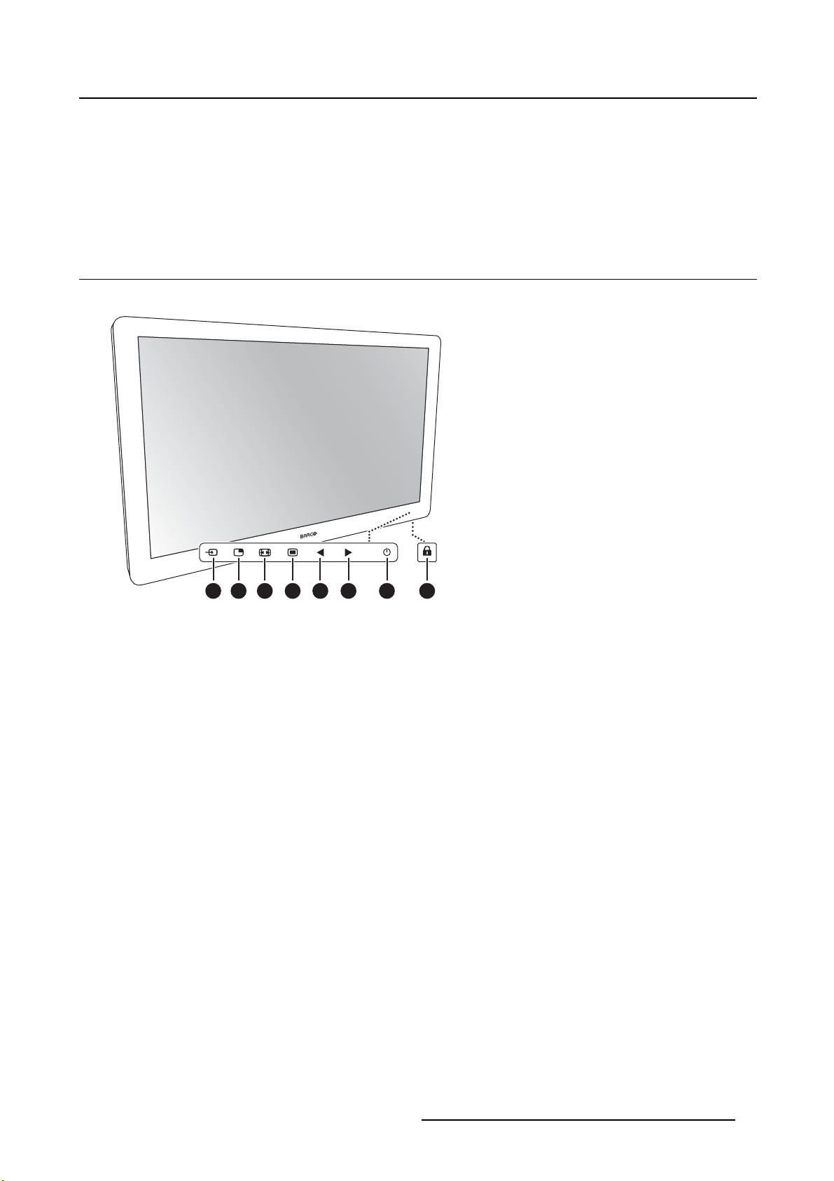
1
2
3 4 5 6 7 8
Image 2- 1
1. Input Selection key
2. Multi-image selection key / Down key
3. Image zoom key / Up key
4. OSD Menu key / Enter key
5. Brightness decrease / Left key
6. Brightness increase / Right key
7. Stand-by key / Power mode LED
8. Keyboard lock/unlock button (membrane switch at the b
A 7-key capacitive keypad is located on the front of the display. By default only the stand-by key (7) is
visible. For keyboard activation please refer to "Keyboard locking/unlocking", page 23.
ottom of the display)
K5902105 (451920611791) MDSC-2232 25/08/2015
5
Page 8
2. Parts, controls and connectors
2.2 Rear view
Overview
1
2
3
4
Image 2- 2
1. VESA mount screw holes (100 x 100 mm, 200 x 100 mm)
2. Cable routing channel
3. Cable routing channel expansion clip
4. Connector compartment cover
2.3 Connector view
2.3.1 MDSC-2232 DDI version
Overview
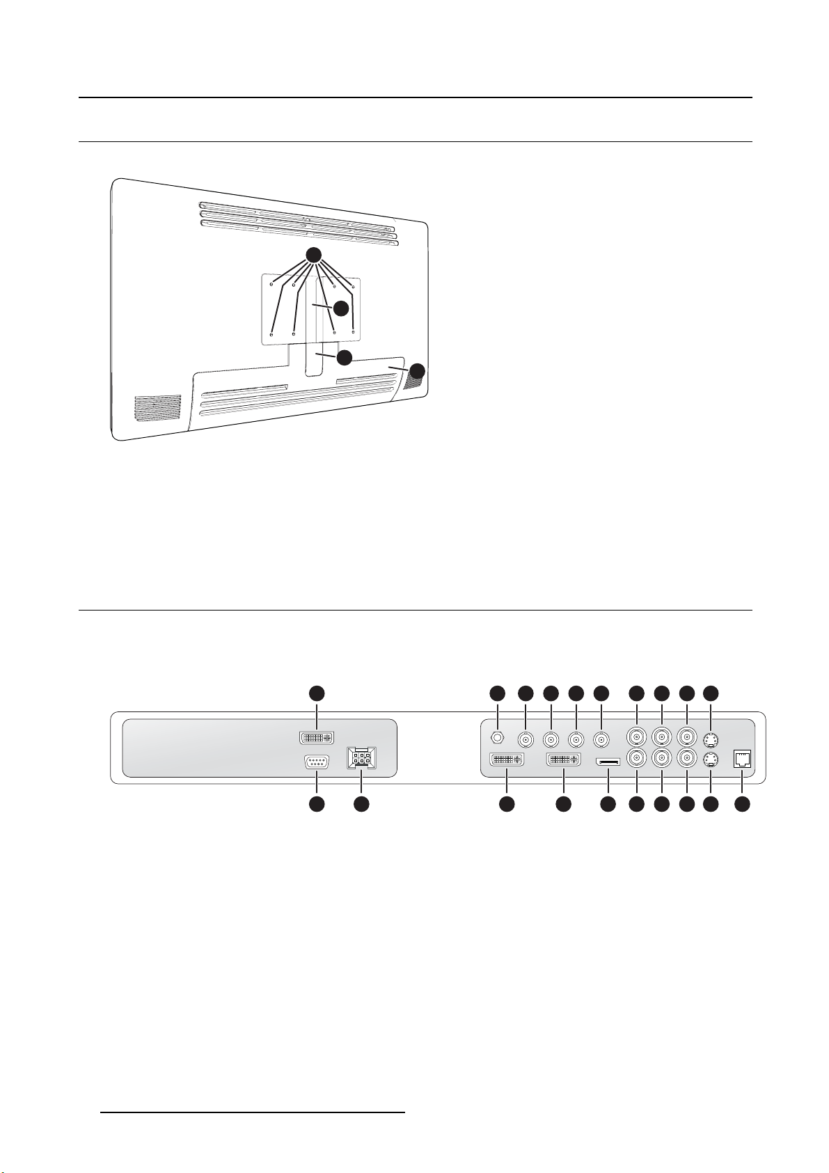
763 4 521 8 9 10
Image 2- 3
1. DVI-2 in
2. Potential Equalization pin (POAG)
3. SDI-2 out
4. SDI-2 in
5. SDI-1 out
6. SDI-1 in
7. Sync
8. CVBS in
9. CVBS out
10. S-Video out
11. RS232
6
11
12 13 14 15 16 17 18 19
K5902105 (451920611791) MDSC-2232 25/08/2015
20
Page 9
12. Input power
13. DVI out
14. DVI-1 in
15. DisplayPort (VESA std 1.1a)
16. R/Pr
17. G/Y
18. B/Pb
19. S-Video in
20. Service
2.3.2 MDSC-2232 MNA version
Overview
2. Parts, controls and connectors
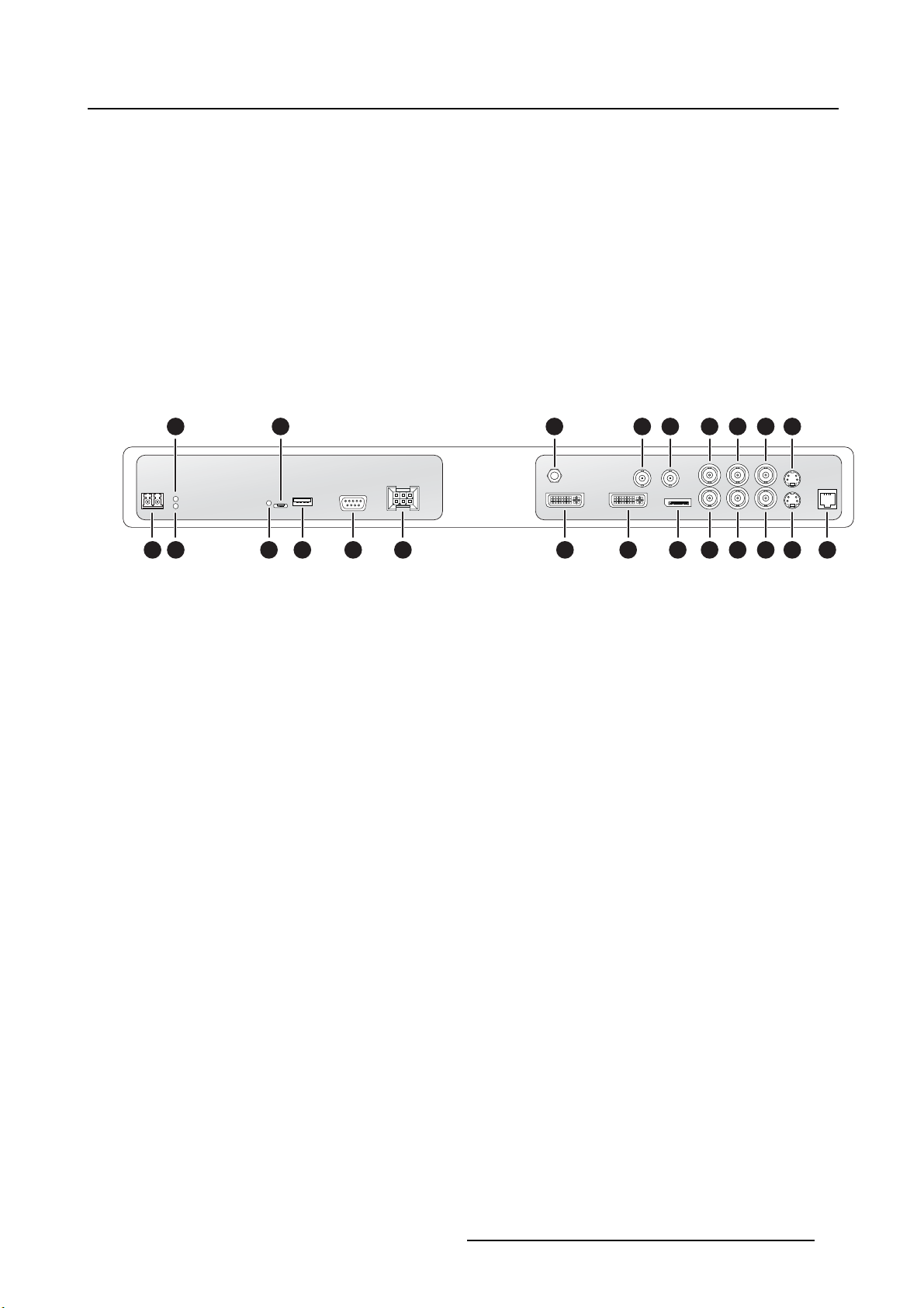
12111093 5 13 14 15
71 2 4 6
Image 2- 4
8 16 17 18 19 20 21 22
1. Optical 10Gb Ethernet SFP+ interface*
2. LED2*
Orange blinking: Activity = (Tx) or (Rx)
Off: No network activity
3. LED1*
Green: Link is active
Off: No active network connection
4. LED3*
Green: Power on, normal operation
Off: System not powered
Orange blinking: Error
5. Micro USB interface*
6. USB 2.0 type A interface*
7. RS232
8. Input power
9. Potential Equalization pin (POAG)
10. SDI out**
11. SDI in**
12. Sync
13. CVBS in
14. CVBS out
15. S-Video out
16. DVI out
17. DVI-1 in
18. DisplayPort (VESA std 1.1a)
19. R/Pr
20. G/Y
21. B/Pb
22. S-Video in
23
K5902105 (451920611791) MDSC-2232 25/08/2015
7
Page 10
2. Parts, controls and connectors
23. Service
(*) Nexxis OR functionality: for more detailed information on Barco’s Nexxis integrated OR solution please
refer to the dedicated user guides. Please visit m
(**) SDI is not always present in combination with Nexxis input.
y.barco.com to obtain these user guides.
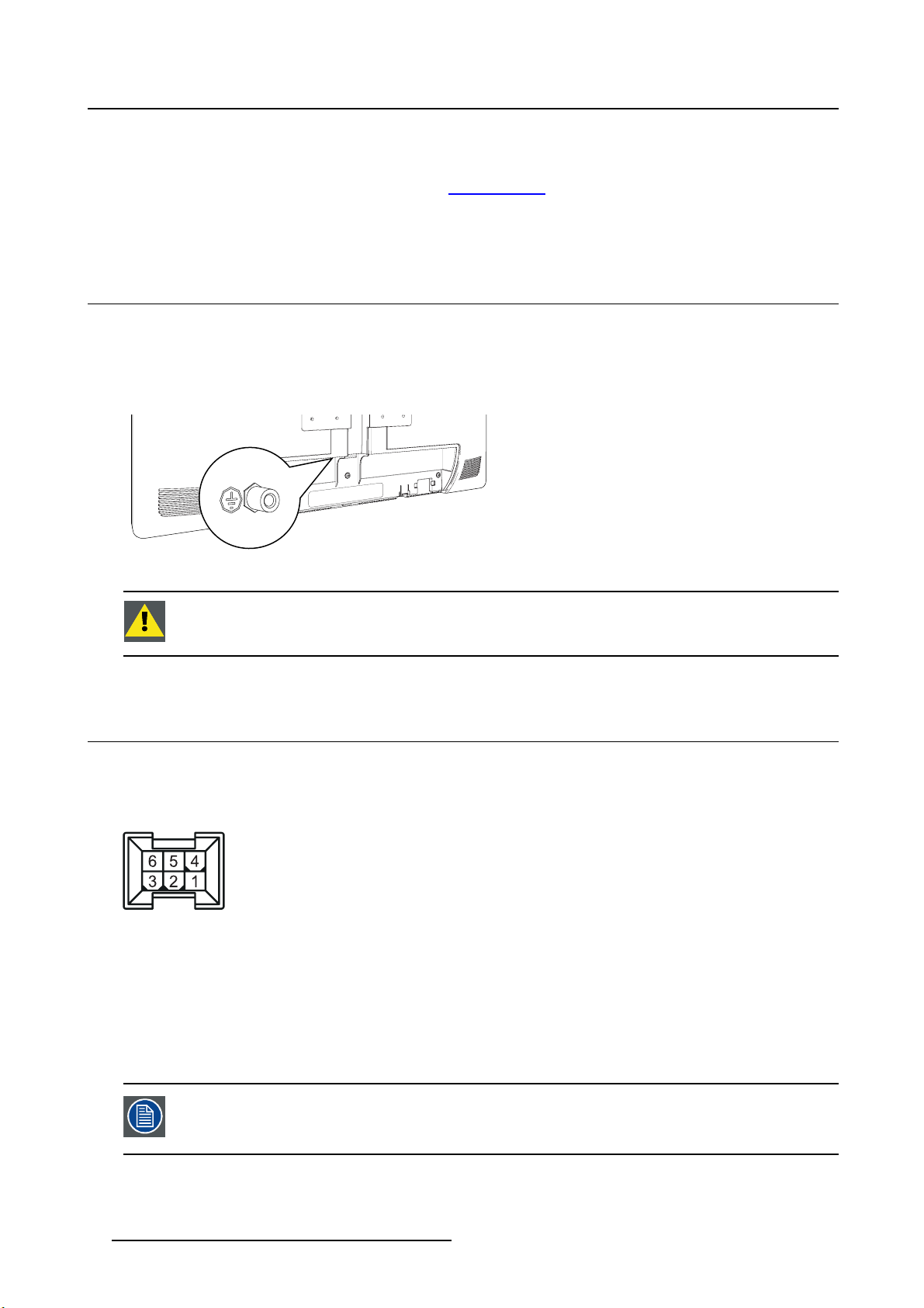
2.4 Protective earth pin
Overview
The MDSC-2232 display can be connected to Protective Earth by this pin and through a yellow/green cable AWG18 minimum, according to national Regulation requirements regarding maximum admitted cable
length.
Image 2- 5
CAUTION: The display must be earthed.
2.5 Connector pin assignments
2.5.1 Input power connector
Overview
Image 2- 6
1. GND
2. Not connected
3. +24 VDC
4. GND
5. Shield
6. +24 VDC
The ground and the shield connections on the power input connector have no Protective Earth function. A Protective Earth connection is provided via a dedicated pi n (see
"Protective earth pin", page 8 ).
8 K5902105 (451920611791) MDSC-2232 25/08/2015
Page 11
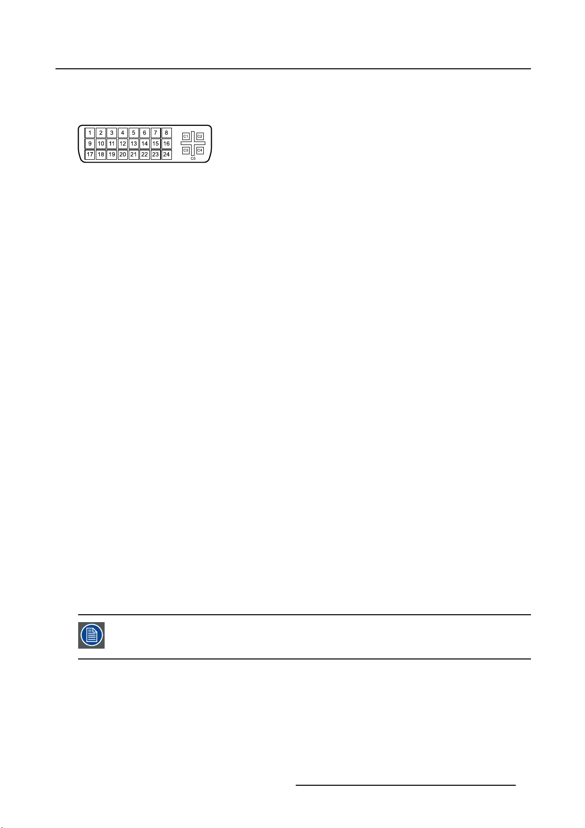
2.5.2 DVI-1 connector (DVI-I)
Overview
Image 2- 7
1. D2_Rx- (T.M.D.S.)
2. D2_Rx+ (T.M.D.S.)
3. GND (data 2 shield)
4. Not connected
5. Not connected
6. SCL (for DDC)
7. SDA (for DDC)
8. Analog vertical sync
9. D1_Rx- (T.M.D.S.)
10. D1_Rx+ (T.M.D.S.)
11. GND (data 1 shield)
12. Not connected
13. Not connected
14. +5V input (DDC supply) (*)
15. GND (cable sense)
16. Hot plug detect (*)
17. D0_Rx- (T.M.D.S.)
18. D0_Rx+ (T.M.D.S.)
19. GND (data 0 shield)
20. Not connected
21. Not connected
22. GND (clock shield)
23. CK_Rx+ (T.M.D.S.)
24. CK_Rx- (T.M.D.S.)
25. C1: Analog Red
26. C2: Analog Green
27. C3: Analog Blue
28. C4: Analog horizontal sync
29. C5: Analog GND return (analog R, G, B)
2. Parts, controls and connectors
(*) +5 VDC output selectable on either pin 14 or 16 via the OSD menu. (+5V ± 10% @ 500mA (max))
PC analog (VGA) input source can be connected to the DVI-I input connector using a
DVI-I to VGA adapter. The use of an adapter cable of at least 0.15 m long will allow an
easy placement inside the cable cover.
K5902105 (451920611791) MDSC-2232 25/08/2015 9
Page 12
2. Parts, controls and connectors
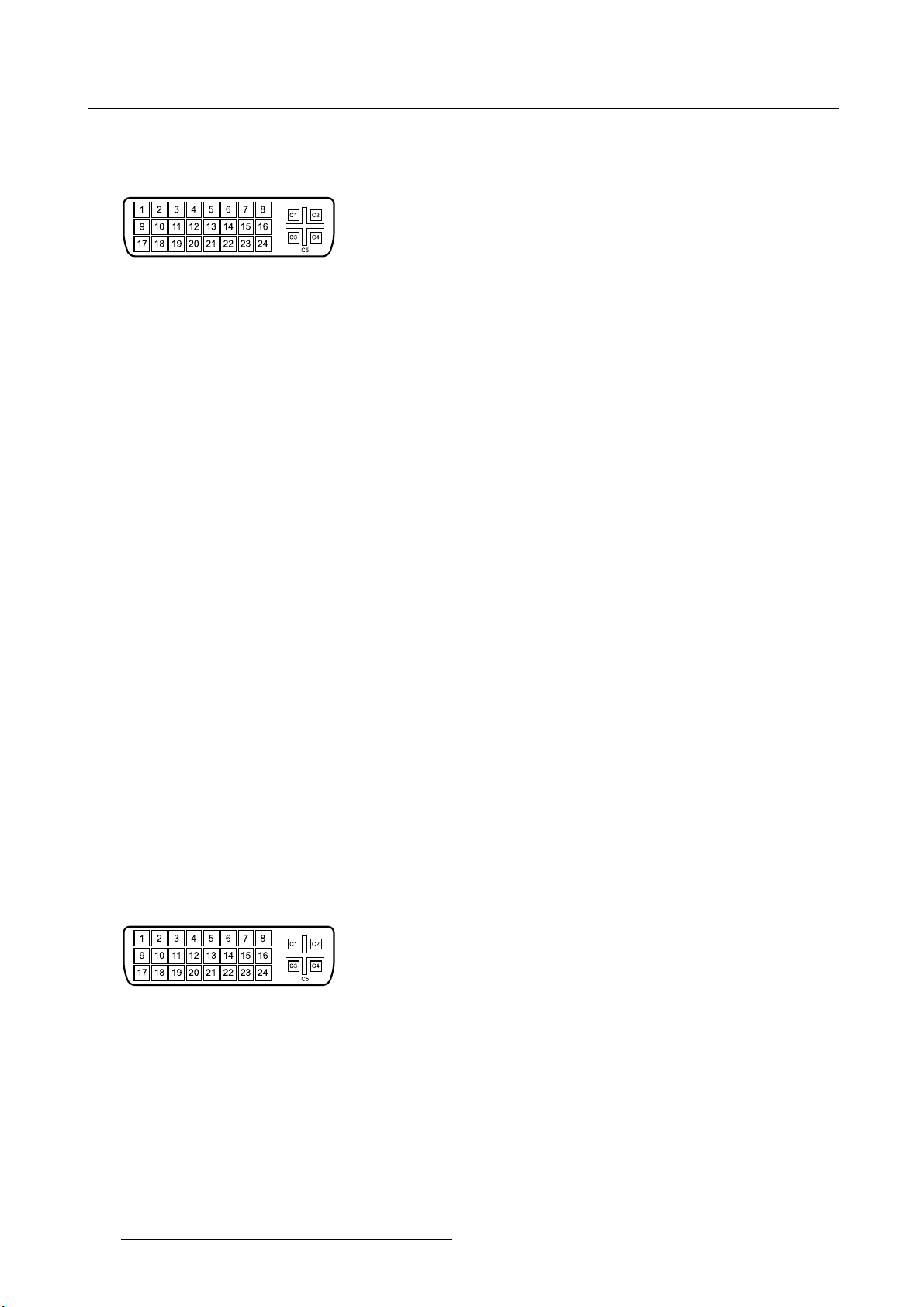
2.5.3 DVI-2 connector (DVI-D)
Overview
Image 2- 8
1. D2_Rx- (T.M.D.S.)
2. D2_Rx+ (T.M.D.S.)
3. GND (data 2 shield)
4. Not connected
5. Not connected
6. SCL (for DDC)
7. SDA (for DDC)
8. Not connected
9. D1_Rx- (T.M.D.S.)
10. D1_Rx+ (T.M.D.S.)
11. GND (data 1 shield)
12. Not connected
13. Not connected
14. +5V input (DDC supply) (*)
15. GND (cable sense)
16. Hot plug detect (*)
17. D0_Rx- (T.M.D.S.)
18. D0_Rx+ (T.M.D.S.)
19. GND (data 0 shield)
20. Not connected
21. Not connected
22. GND (clock shield)
23. CK_Rx+ (T.M.D.S.)
24. CK_Rx- (T.M.D.S.)
(*) +5 VDC output selectable on either pin 14 or 16 via the OSD menu. (+5V ± 10% @ 500mA (max))
2.5.4 DVI out connector (DVI-D)
Overview
Image 2- 9
10 K5902105 (451920611791) MDSC-2232 25/08/2015
Page 13
1. D2_Rx- (T.M.D.S.)
2. D2_Rx+ (T.M.D.S.)
3. GND (data 2 shield)
4. Not connected
5. Not connected
6. SCL (for DDC)
7. SDA (for DDC)
8. Not connected
9. D1_Rx- (T.M.D.S.)
10. D1_Rx+ (T.M.D.S.)
11. GND (data 1 shield)
12. Not connected
13. Not connected
14. +5V output (*)
15. GND (cable sense)
16. Hot plug detect
17. D0_Rx- (T.M.D.S.)
18. D0_Rx+ (T.M.D.S.)
19. GND (data 0 shield)
20. Not connected
21. Not connected
22. GND (clock shield)
23. CK_Rx+ (T.M.D.S.)
24. CK_Rx- (T.M.D.S.)
2. Parts, controls and connectors
(*) +5 VDC output always available. (+5V ± 10% @ 500mA (max))
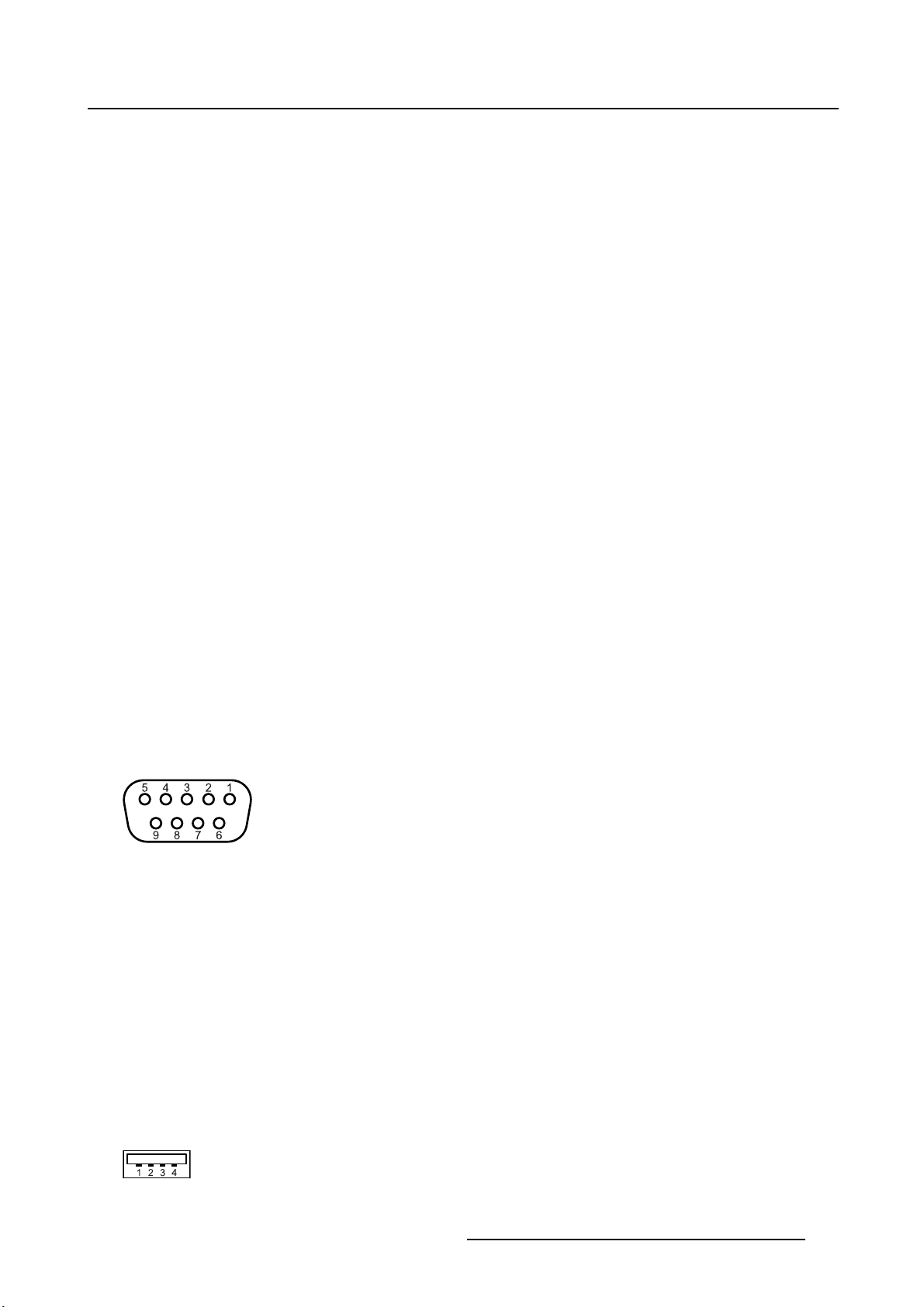
2.5.5 RS232 connector
Overview
Image 2-1 0
1. Not connected
2. Rx (driven by host)
3. Tx (driven by display)
4. Not connected
5. Ground
6. Not connected
7. Not connected
8. Not connected
9. Not connected
2.5.6 USB connector
Overview
Image 2-11
K5902105 (451920611791) MDSC-2232 25/08/2015 11
Page 14
2. Parts, controls and connectors
1. +5 VDC
2. Data -
3. Data +
4. GND
2.5.7 Mini USB connector
Overview
12345
Image 2-1 2
1. +5 VDC
2. Data -
3. Data +
4. Not connected
5. GND
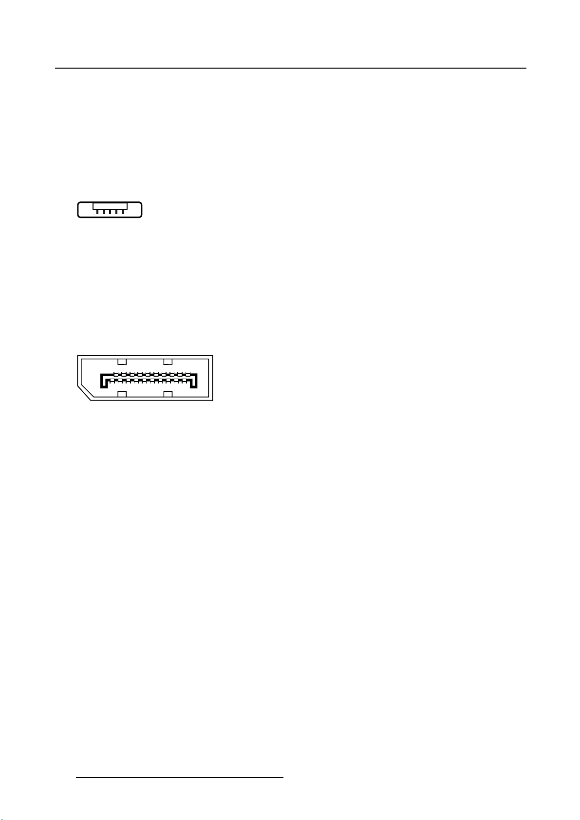
2.5.8 DisplayPort connector
Overview
19 17 15 13 11 9 7 5 3 1
20 18 16 14 12 10 8 6 4 2
Image 2-1 3
1. ML_Lane 0 (p)
2. GND
3. ML_Lane 0 (n)
4. ML_Lane 1 (p)
5. GND
6. ML_Lane 1 (n)
7. ML_Lane 2 (p)
8. GND
9. ML_Lane 2 (n)
10. ML_Lane 3 (p)
11. GND
12. ML_Lane 3 (n)
13. CONFIG1
14. CONFIG2
15. AUX CH (p)
16. GND
17. AUX CH (n)
18. Hot Plug
19. Return
20. DP_PWR (+3.3 VDC)
12
K5902105 (451920611791) MDSC-2232 25/08/2015
Page 15

2.5.9 S-Video and S-Video-out connector
Overview
Image 2-1 4
1. Ground (Y)
2. Ground (C)
3. Luminance (Y)
4. Chroma (C)
5. SG: Shielded Ground
2. Parts, controls and connectors
K5902105 (451920611791) MDSC-2232 25/08/2015
13
Page 16

2. Parts, controls and connectors
14 K5902105 (451920611791) MDSC-2232 25/08/2015
Page 17
3. DISPLAY INSTALLATION
3.1 Cover rem oval
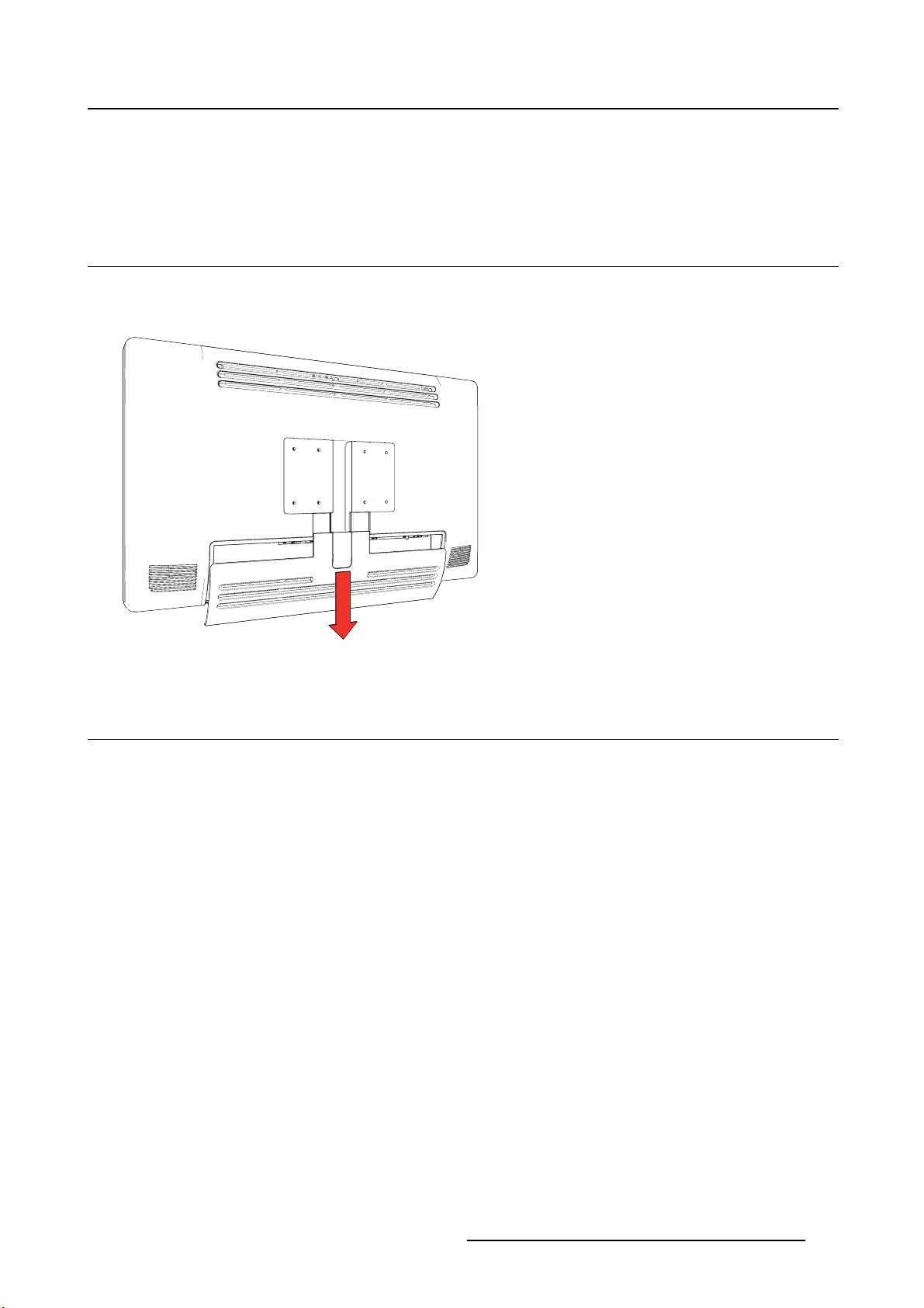
To remove the connector compartment cover
Slide the connector compartment cover downwards to get access to the connectors.
3. Display installation
Image 3- 1
3.2 Interface connection
About the interfaces
The MDSC-2232 can have multiple different video inputs connected (depending on the display version).
Switching between the different inputs can be easily done by pressing the direct access key for this. See
the dedicated section for more info.
Futhermore, if more than one video source is connected, the Picture in Picture (PiP) and Side-by-Side
(SbS) functionality becomes available, allowing you to view two different video inputs at once. Please
refer to the dedicated chapter for more info on how to activate and use the PiP and SbS features on your
MDSC-2232.
Beside the video input connections, the MDSC-2232 also has video output capabilities allowing you to
loop-through certain video inputs connected with the MDSC-2232 to another display, projector, video
recorder, ...
This chapter describes how to connect the different video interface types to the MDSC-2232.
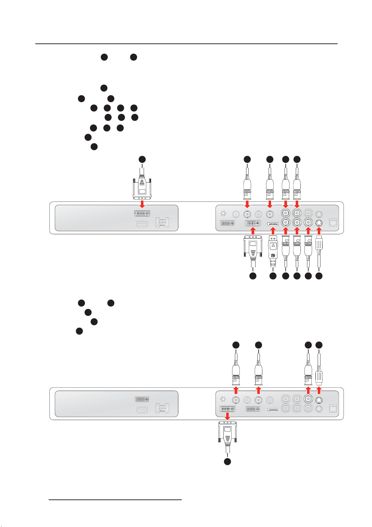
3.2.1 MDSC-2232 DDI version
To connect the interfaces
1. Connect one or more video source(s) to the corresponding video inputs of the display.
K5902105 (451920611791) MDSC-2232 25/08/2015
15
Page 18
3. Display installation
- DVI or VGA:1and/or
6
PC analog (VGA) input source can be connected to the DVI-I input connector using a DVI-I to VGA
adapter. The use of an adapter cable of at least 0.15 m long will allow an easy placement inside the
cable cover.
-DisplayPort:
-SDI:2and/or
- R/G/B/S:8/9/10/
- R/G/B (SOG):8/9/
-Y/Pb/Pr:9/10/
- CVBS:
- S-Video:
7
3
4
10
8
5
11
1
2
3
4 5
6 8 9
Image 3- 2
7 10 11
2. Connect one or more of the available video sink(s) to the corresponding video outputs.
-SDI:
1
- CVBS:
- S-Video:
and/or
3
2
4
-DVI:5(to be configured in OSD menu, see "DVI Output", page 47)
1
2
3
4
5
Image 3- 3
16 K5902105 (451920611791) MDSC-2232 25/08/2015
Page 19
WARNING: To maintain compliance with EMC regulation, use only shielded interface
cables for the connection to peripheral devices.
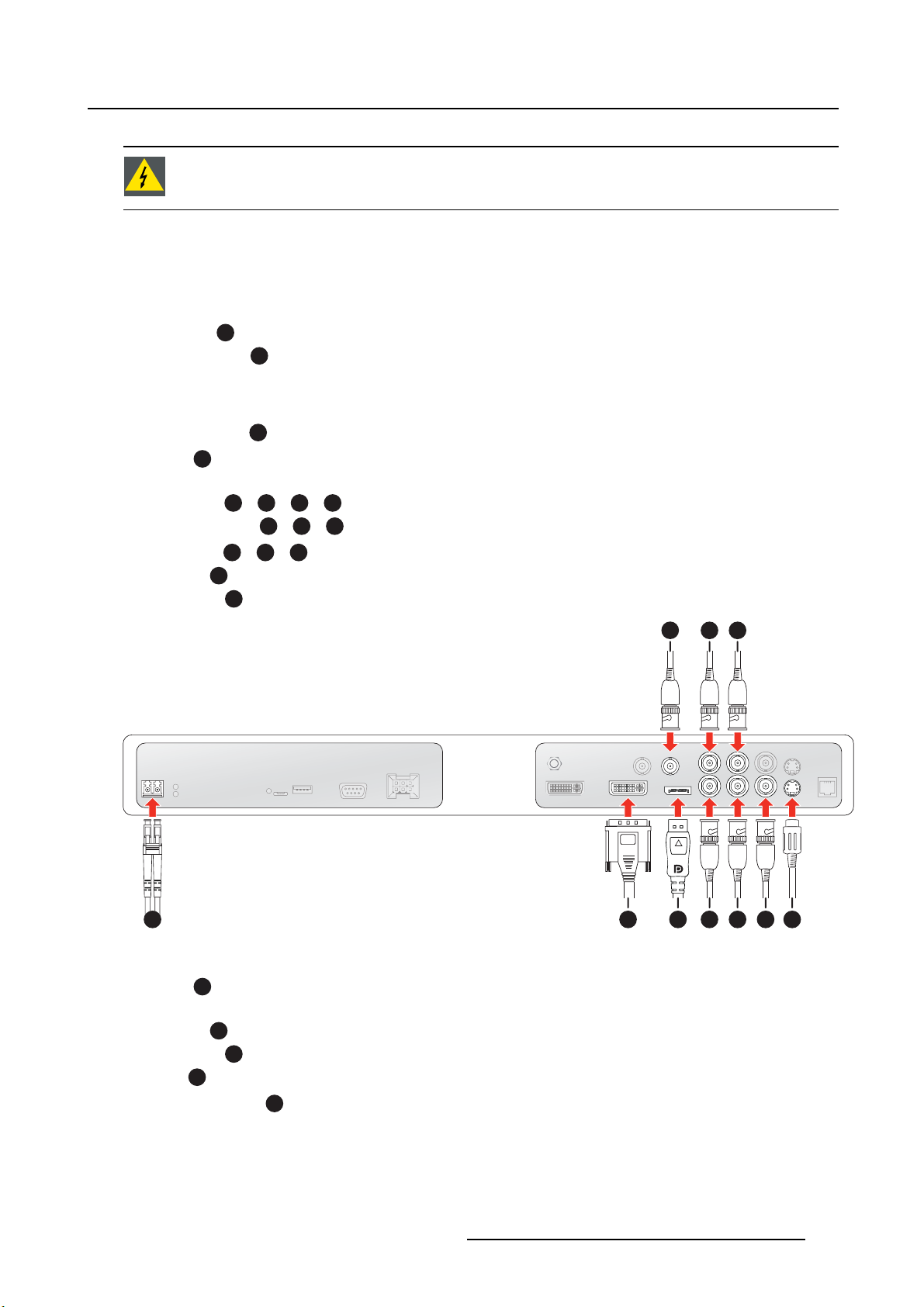
3.2.2 MDSC-2232 MNA version
To connect the interfaces
1. Connect one or more video source(s) to the corresponding video inputs of the display.
-Nexxis:
- DVI or VGA:
PC analog (VGA) input source can be connected to the DVI-I input connector using a DVI-I to VGA
adapter. The use of an adapter cable of at least 0.15 m long will allow an easy placement inside the
cable cover.
-DisplayPort:
-SDI:
SDI is not always present in combination with Nexxis input.
- R/G/B/S:
- R/G/B (SOG):7/8/
-Y/Pb/Pr:8/9/
- CVBS:
- S-Video:
4
5
6
1
7/8/9/2
9
7
3
10
3. Display installation
1
2 3
5 7 86 9 104
Image 3- 4
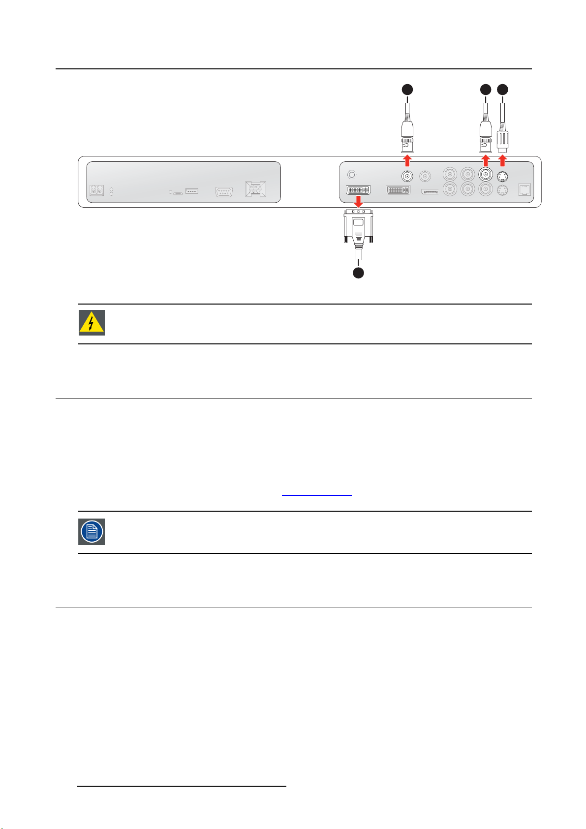
2. Connect one or more of the available video sink(s) to the corresponding video outputs.
-SDI:
1
SDI is not always present in combination with Nexxis input.
- CVBS:
- S-Video:
-DVI:4(to be configured in OSD menu, see "DVI Ou
-NexxisonDVI:
2
3
tput", page 47)
4
(tobeconfigured in OSD menu, see "DVI Output", page 47)
K5902105 (451920611791) MDSC-2232 25/08/2015
17
Page 20
3. Display installation
Image 3- 5
1
4
2
3
WARNING: To maintain compliance with EMC regulation, use only shielded interface
cables for the connection to peripheral devices.
3.3 Nexxis OR
Overview
Connecting your MDSC-2232 to Barco’s Nexxis OR system allows you to distribute video, graphics, audio
and computer data over the IP network, in raw uncompressed format, inside the operating room and even
between surgical suites.
To connect your MDSC-2232 to Barco’s Nexxis OR system, connect the 10Gb Ethernet interface to your
Nexxis switch. More info about Nexxis OR and how to configure the MDSC-2232 in your network is available in the dedicated user guides. Please visit w
Nexxis OR is only available on the MDSC-2232 MNA version.
ww.barco.com to obtain these user guides.
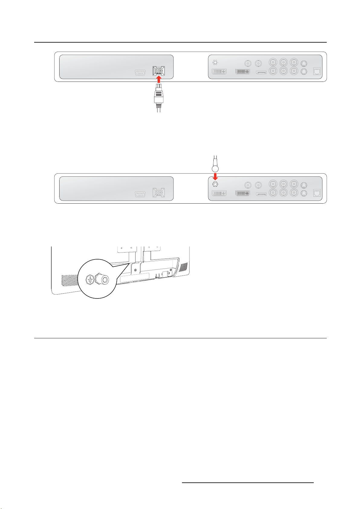
3.4 Power supply connection
To connect the power supply
1. Connect the supplied external DC power supply unit to the +24 VDC power input of your MDSC-2232
display.
2. Plug the other end of the external DC power supply into a grounded power outlet by means of the
proper power cord delivered in the packaging.
Warning:To avoid risk of electric shock, the external DC power supply must be connected to a mains
with protective earth. The ground
no protective earth function. The MDSC-2232 display protective earth connection is provided
viaadedicatepin(seenextsteps).
connection on the display’s DC power input connector has
18
K5902105 (451920611791) MDSC-2232 25/08/2015
Page 21
3. Display installation
Image 3- 6
Potential equalization
When potential equalization between the display and other devices is required then connect the potential
equalization pin (POAG) to the potential equalization terminal of the equipment.
Image 3- 7
Protective earth
Earth the MDSC-2232 by connecting the protective earth pin to a
wire (maximum admitted cable length according to national regulation requirements).
Image 3- 8
grounded outlet by means of an AWG18
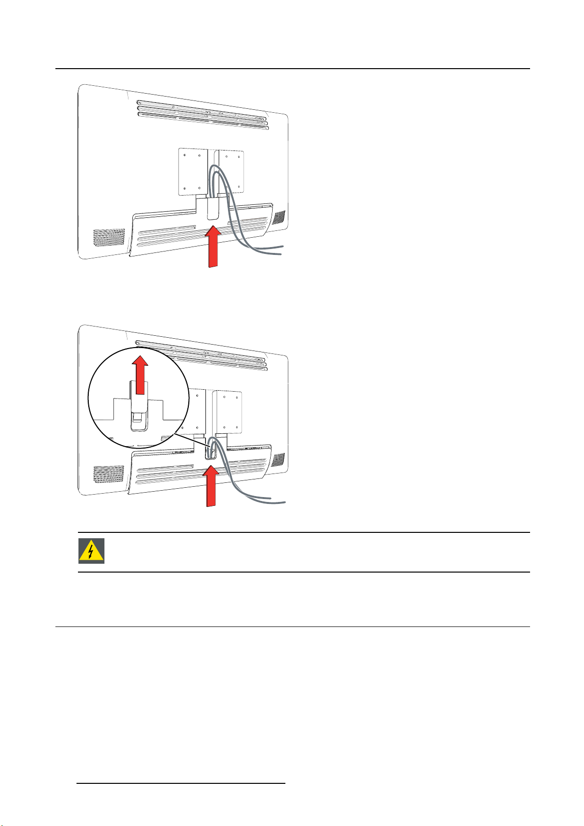
3.5 Cable routing
To route the cables
For displays to be mounted on a VESA arm with internal cable routing provisions, route all cables through
the cable routing channel, then reinstall the connector compartment without removing the expansion clip.
K5902105 (451920611791) MDSC-2232 25/08/2015
19
Page 22
3. Display installation
Image 3- 9
For displays to be mounted on a VESA arm or stand without internal cable routing provisions, first remove
the expansion clip from the connector compartment cover, then route all cables through it while reinstalling
the cover.
Image 3-1 0
WARNING: When the display is assembled in the medical system, take care of the fixa-
tion of all cables, to avoid unwanted detachment.
3.6 VESA mount installation
To install the display on a VESA mounting solution
Attach the display to a VESA arm or stand (VESA 100 mm or VESA 200 mm are supported) by making
use of the included 4 screws (M4 x 20 mm) and the dented washers.
20
K5902105 (451920611791) MDSC-2232 25/08/2015
Page 23

Image 3-11
3. Display installation
CAUTION: The 4 screws included (M4 x 20 mm) can be used for a VESA arm interface
with a thick ness of up to 10 mm.
If, due to the thickness of the VESA arm interface (=V), the length of the provided screws
(=L) is not suitable, consider the following rule: L = V + 15 mm
CAUTION: Use an arm that is in compliance with VESA requirements.
CAUTION: Use an arm that can support a weight of least 20 kg (44,09 lbs).
The monitor VESA interface has been designed for a safety factor 6 (to support 6 times
the monitor weight). In the medical system, use an arm with suitable safety factor
(IEC60601–1).
K5902105 (451920611791) MDSC-2232 25/08/2015 21
Page 24

3. Display installation
22 K5902105 (451920611791) MDSC-2232 25/08/2015
Page 25
4. Daily operation
4. DAILY OPERATION
4.1 On/Off switching
To switch on your display:
1. Activate the power supply through the switch located on the external power supply .
2. While your display is off, press and hold (approximately 3-4 seconds) the stand-by key until the keyboard backlight starts blinking.
3. Once the blinking state begins, release the key within 2 seconds to avoid the keyboard relock.
When the keyboard backlight starts blinking, the LED status changes to full green showing the monitor is switching on.
To switch off you display;
1. While your display is switched on, unlock the keyboard (see "Keyboard locking/unlocking", page 23).
2. Press and hold (approximately 3-4 seconds) the stand-by key until the keyboard backlight starts blinking.
3. Once the blinking state begins, release the key within 2 seconds to avoid the keyboard relock.
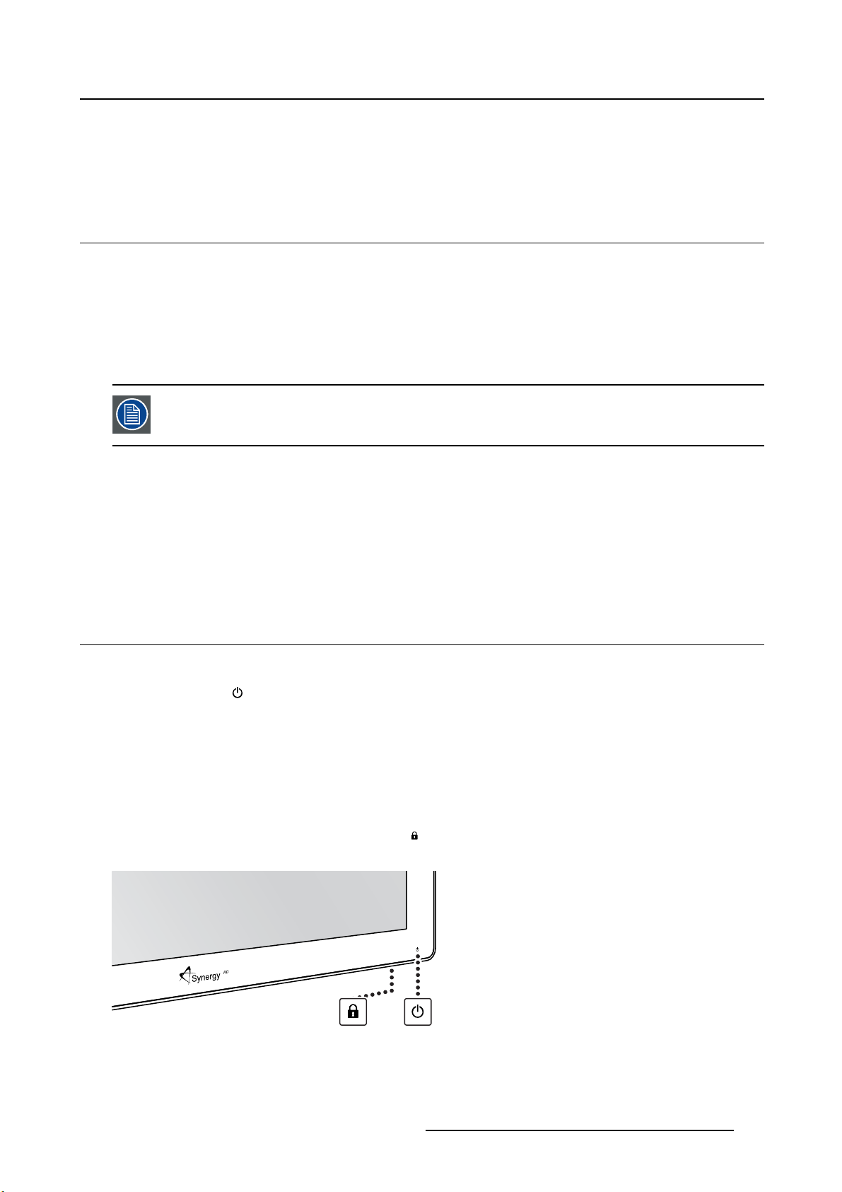
4.2 Keyboard locking/unlo cking
About the keyboard backlight
By default only the key is visible. After unlocking the keyboard, all keys will light up for a few seconds.
When you touch any of these keys again while the backlight
no further action is taken within the time-out, the keyboard will lock again.
To unlock the keyboard:
In order to avoid unwanted or accidental activation of the OSD keyboard, a lock/unlock mechanism has
been implemented. This means that, before the keyboard can be used to change any of the settings of
the display, it needs to be unlocked. Two options are available to unlock the keyboard:
1. Option 1: Press the Keyboard unlock button (
it when the keyboard is illuminated.
) at the bottom of the display for 3 seconds and release
is on, the function of the key is executed. If
Image 4- 1
K5902105 (451920611791) MDSC-2232 25/08/2015 23
Page 26

4. Daily operation
As a result, the keys will light up and are now available for further actions. However, if no further actions
are taken within the following 10 seconds, the keys will dim and the keyboard will be locked again.
2. Option 2: Press the Standy key (
) for 3 seconds and release it when the keyboard is illuminated.
To lock the keyboard:
The keyboard will automatically lock after 10 seconds of inactivity, except while navigating the OSD menu,
during which it remains unlocked.
As a result, all keys except the
key will dim to indicate that the keyboard is locked.
4.3 Power mode LED
About the power mode LED
The behavior of the power LED shows the status of the unit:
OFF Hard OFF (power supply is unplugged)
Blinking orange
Full orange
Blinking green / orange Searching for signal
Full green Display has an image on the screen
Soft OFF (switching off by using the stand-by key (
Display is in power save mode (backlight and LCD off)
Note: When Power save mode is enabled, the display will automatically go i
power save mode after 10 seconds of searching without signal.
))
nto
4.4 OSD menu activation
To activate the OSD menu
1. Switch on the display (see "On/Off switching", page 23).
2. Unlock the keyboard (see "Keyboard locking/unlocking", page 23).
3. Press the
As a result, the OSD main menu comes up in the bottom right corner of the screen. If no further actions
are taken within the following 30 seconds, the OSD menu will disappear again.
If after pressing the
enabled. Please refer to "Menu locking/unlocking", page 31for more information and instructions to
unlock the OSD menu.
key.
key, the OSD lock window appears then this means that the OSD lock has been
The time-out of the OSD menu automatic close function can be adjusted or disabled in
the OSD menu (OSD Time-out).
The OSD menu position can be adjusted in the OSD menu (OSD Hor. Pos. and OSD Vert.
Pos.).
24 K5902105 (451920611791) MDSC-2232 25/08/2015
Page 27

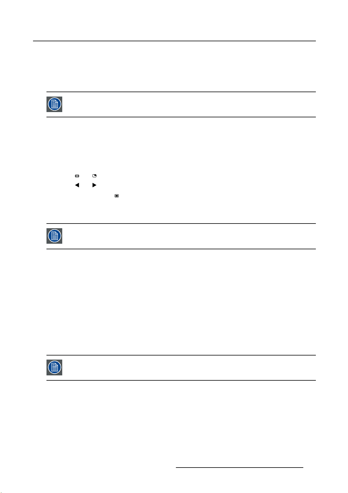
4.5 OSD menu navigation
OSD menu structure explained
Below is an example of the OSD menu structure:
5
Picture
Profile Factory
Brightness 50
Contrast 50
1
Image 4- 2
Saturation 30
Color temperature 6500K
Gamma Native
Sharpness 10
DVI 1280x800@60Hz
32 4
4. Daily operation
6
1
2
3
4
5
6
Menu
Sub-menu
Status bar
Legend (shows the functionality associated to each keyboard key)
Selector/Slider
Item
To navigate through the OSD menu
Image 4- 3
•Pressthekey to open the OSD menu.
•Usethe
• When the desired Menu page is highlighted, press the
highlighted.
•Usethe
• If the selected menu item is controlled by a slider use the
press the
• If the selected menu item is a multiple choices menu use the
then press the
• Press again
or key to scroll to the desired menu page.
key to select the top menu item that will be
or keys to move to other Menu Items, then press the key to select it.
key to confirm.
key to confirm.
or key to select other Menu items or exit from the Menu page by pressing the key.
or keys to adjust the item value, then
or keys to select the desired option
4.6 Shortkey functions
About shortkey functions
The concept of shortkey functions is to present a selection of commonly used functions immediately available without the need to navigate through the OSD Menu.
K5902105 (451920611791) MDSC-2232 25/08/2015
25
Page 28

4. Daily operation
The different available shortkey functions are:
• Main source selection
•Multi-imageconfiguration
• Zoom factor selection
• Brightness adjustment
Unlike the extended keyboard functions (described in next chapter), the shortkey functionality is immediately available w ithout the need to first enable this i n the OSD menu.
When the extended keyboard functionality is enabled, all the shortkey functions described below (except for the brightness adjustment), will no longer be available and
will be replaced by the corresponding extended keyboard functions described in the
next chapter.
Overview of shortkeys
1
2
3 4 5
Image 4- 4
1
2
3
4
5
Main source selection
Multi-image configuration
Zoom factor selection
Brightness decrease
Brightness increase
4.6.1 Main source selection
To quickly select the main source
1. Use the Input selection key ( ) to scroll through all the possible input signals to select the main input
source.
When the extended keyboard functionality is enabled, the shortkey functions will no
longer be available and will be replaced by the corresponding extended keyboard functions described in the next chapter.
4.6.2 Multi-image configuration
To quickly select the multi-image configuration
1. Use the PiP selection key ( ) to scroll through all possible configurations of Picture-in-Picture (PiP) and
Side-by-Side (SbS).
The different PiP/SbS options are:
- Small PiP: 30% of Primary height in top-right corner
- Large PiP: 50% of Primary height in top-right corner
- Side-by-Side: Primary and Secondary input of equal height
26
K5902105 (451920611791) MDSC-2232 25/08/2015
Page 29

Only a subset of multi-image configuration settings is available via this shortkey function. More multi-image configuration settings can be selected in the OSD menus.
When the extended keyboard functionality is enabled, this shortkey functions will no
longer be available and will be replaced by the corresponding extended keyboard functions described in the next chapter.
4.6.3 Zoom factor selection
To quickly select the zoom factor
1. Use the Image zoom key ( ) to select one of the available zoom factors.
When the extended keyboard functionality is enabled, the shortkey functions will no
longer be available and will be replaced by the corresponding extended keyboard functions described in the next chapter.
4. Daily operation
4.6.4 Brightness adjustment
To quickly adjust the brightness
1. While no OSD Menu is on the screen, press the Brightness decrease ( ) or Brightness increase ( )
keys to adjust the brightness as desired.
Brightness
50
Image 4- 5
When the extended keyboard functionality is enabled, this shortkey functions will remain available.
4.7 Extended keyboard function s
About extended keyboard functions
The concept of the extended keyboard is to present a large selection of functions immediately available
to the user without the need to navigate through the OSD Menu.
Once enabled through dedicated OSD menu function, by simply pressing one of the first 3 keys on the left
the user is presented with a list of new selections displayed on screen; the new choices can be selected
by using each of the key just below the OSD text.
If two options are available for one key, the first key press will select the upper option, a second press
selects the lower option.
The different available extended keyboard functions are:
K5902105 (451920611791) MDSC-2232 25/08/2015
27
Page 30

4. Daily operation
• Main source selection
• Second source selection
•Multi-imageconfiguration
• Color temperature selection
• Image size selection
• Zoom factor selection
Unlike the shortkey functions (described before), the extended keyboard functionality
must be first enabled in the OSD menu before you can make use of it. Please refer to the
dedicated section in this manual for more details on how to enable/disable the extended
keyboard functions.
When the extended keyboard functionality is enabled, all the shortkey functions described in previous chapter (except for the brightness adjustment), will no longer be
available and will be replaced by the corresponding extended keyboard functions described below.
Overview of extended keyboard
1
2
3
Image 4- 6
1
Main source selection
Second source selection
2
3
Multi-image configuration
Color temperature selection
Image size selection
Zoom factor selection
4.7.1 Main source selection
To quickly select the main source
1. While no OSD Menu is on the screen, press the Input selection key ( ) to bring up the main source
quick selection menu.
2. Toggle the available main source options by pressing th
If two options are available for one key, the first key press will select the upper option, a second press
selects the lower option.
Thecurrentselectionismarkedinred.
3. Press the stand-by key (
)toconfirm your choice and exit the main source quick selection menu.
e key corresponding to the desired option.
28
K5902105 (451920611791) MDSC-2232 25/08/2015
Page 31

4. Daily operation
Main source
VGADPR G B
Image 4- 7
Y Pb Pr
S-Video
CVBS
DVI
SDI Nexxis 2nd Source
E
X
I
T
4.7.2 Second source selection
To quickly select the second source
1. While no OSD Menu is on the screen, press the Input selection key ( ) to bring up the main source
quick selection menu.
2. Press the
3. Toggle the available second source options by pressing the key correspo
If two options are available for one key, the first key press will select the upper option, a second press
selects the lower option.
Thecurrentselectionismarkedinred.
4. Press the stand-by key (
2nd Source
VGADPR G B
keytoswitchtothe2ndsourcequickselectionmenu.
)toconfi rm your choice and exit the second source quick selection menu.
E
X
I
T
Y Pb Pr
S-Video
CVBS
DVI
SDI Nexxis Main source
nding to the desired option.
Image 4- 8
4.7.3 Multi-image configuration
To quickly select the multi-image configuration
1. While no OSD Menu is on the screen, press the PiP selection key ( ) to bring up the multi-image
configuration quick selection menu.
2. Toggle the available multi-image configurations by pressing the key corresponding to the desired option.
Thecurrentselectionismarkedinred.
3. Press the stand-by key (
menu.
Multi image config.
Native Aspect Fill Small Large None
Image 4- 9
)toconfirm your choice and exit the multi-image configuration quick selection
E
X
I
T
K5902105 (451920611791) MDSC-2232 25/08/2015 29
Page 32

4. Daily operation
4.7.4 Common Functions: Transfer function selection
To quickly select the transfer function
1. While no OSD Menu is on the screen, press the Image zoom key ( ) to bring up the common functions
quick selection menu.
2. Toggle the available transfer function settings by pressing the key corresponding to the desired option.
Thecurrentselectionismarkedinred.
3. Press the stand-by key (
Common Functions
ITU 709 6500°K DICOM Native Aspect Zoom
Image 4-1 0
)toconfirm your choice and exit the common functions quick selection menu.
E
X
10%
I
T
Note: Only a subset of transfer function settings is available via this quick selection menu. More transfer
function settings can be selected in the OSD menus.
4.7.5 Common Fun ctions: Image size selection
To quickly select the image size
1. While no OSD Menu is on the screen, press the Image zoom key ( ) to bring up the common functions
quick selection menu.
2. Toggle the available image size settings by pressing the key correspo
Thecurrentselectionismarkedinred.
3. Press the stand-by key (
)toconfirm your choice and exit the common functions quick selection menu.
nding to the desired option.
Common Functions
ITU 709 6500°K DICOM Native Aspect Zoom
Image 4-11
10%
E
X
I
T
Note: Only a subset of image size settings is available via this quick selection menu. More image size
settings can be selected in the OSD menus.
4.7.6 Common Functions: Zoom factor selection
To quickly select the zoom factor
1. While no OSD Menu is on the screen, press the Image zoom key ( ) to bring up the common functions
quick selection menu.
2. Toggle the available zoom factors by repeatedly pressing the
shown.
3. Press the stand-by key (
)toconfirm your choice and exit the common functions quick selection menu.
key until the desired zoom factor is
30
K5902105 (451920611791) MDSC-2232 25/08/2015
Page 33

4. Daily operation
Common Functions
ITU 709 6500°K DICOM Native Aspect Zoom
Image 4-1 2
10%
E
X
I
T
4.8 Menu locking/unlocking
To lock/unlock the menu
The keyboard can be locked from the Menu to avoid unwanted access to OSD functions. When the keyboard is LOCKED only the OSD Menu key (
key is pressed the Menu Locked window appears.
1. To unlock the keyboard the following sequence of keys need to be pressed:
, , ,
Each time a key is pressed an asterisk is shown in the square boxes.
After pressing the fourth key, if the sequence is correct, the main OSD menu is activated. To unlock the
keyboard permanently the specific OSD function is required.
) and the Stand-by key ( ) are active. When the Menu OSD
Sequence: 5 - 6 - 6 - 3
Image 4-1 3
Keyboard lock
K5902105 (451920611791) MDSC-2232 25/08/2015 31
Page 34

4. Daily operation
32 K5902105 (451920611791) MDSC-2232 25/08/2015
Page 35

5. ADVANCED OPERATION
5.1 OSD picture menu
Overview
•Profile
• Brightness
• Contrast
• Saturation
• Color temperature
•Gamma
• Sharpness
5.1.1 Profile
About profiles
5. Advanced operation
To select a profile means to load a set of predefined video parameters like Brightness
tion, Input selection (Primary & Secondary), Multi-image layout selection, etc.
The user can modify the default video parameters associated to each profile and save the new parameters
setting under the User 1, User 2 or User 3 profile. The Factory and X Ray profiles can be temporarily
modified, but the factory default can’t be overwritten and can always be recalled through the recall profile
menu item.
The available profiles for your display are:
•Factory
•XRay
•User1
•User2
•User3
, Contrast, Satura-
To se lec t a pro file
1. Bring up the OSD main menu.
2. Navigate to the Picture menu.
3. Enter the Profile submenu.
4. Select one of the available profiles and confirm.
5.1.2 Brightness
To adjust the brightness level
1. Bring up the OSD main menu.
2. Navigate to the Picture menu.
3. Enter the Brightness submenu.
The command bar Brightness is highlighted.
4. Set the brightness level as desired and confirm.
K5902105 (451920611791) MDSC-2232 25/08/2015
33
Page 36

5. Advanced operation
The selected brightness is maintained at a constant level by the automatic backlight
stabilization function.
The brightness level can also be adjusted through a shortkey function.
Brightness level is adjusted by controlling the backlight illumination only.
5.1.3 Contrast
To adjust the contrast level
1. Bring up the OSD main menu.
2. Navigate to the Picture menu.
3. Enter the Contrast submenu.
The command bar Contrast is highlighted.
4. Set the contrast level as desired and confirm.
5.1.4 Saturation
To adjust the saturation level
1. Bring up the OSD main menu.
2. Navigate to the Picture menu.
3. Enter the Saturation submenu.
The command bar Saturation is highlighted.
4. Set the saturation level as desired and confirm.
5.1.5 Color temperature
About color temperature presets
The available color temperature presets for your display are:
• 5600K
• 6500K
• 7600K
• 9300K
• ITU 709
•Native
•User
34
K5902105 (451920611791) MDSC-2232 25/08/2015
Page 37

Factory calibration – White point:
The White Color points associated with the Color Temperature: 5600K, 6500K, 7600K or
9300K are fa ctory calibrated with a consequent reduction of the maximum luminance
compared to Native Color Temperature.
Factory calibration – Color space:
When ITU 709 is selected, the White Color point and the RGB color primaries are adjusted according to the target HDTV / sRGB color space defined in the ITU-709 recommendation. RGB primary calibration is performed within the physical limitation of the
LCD panel used.
Only in case the User preset has been selected it is possible to get access to the color
regulation commands described he reafter.
To select a color temperature preset
1. Bring up the OSD main menu.
5. Advanced operation
2. Navigate to the Picture menu.
3. Enter the Color Temperature submenu.
4. Select one of the available color temperature presets and confirm.
Note: If you selected the User color temperature preset, a new menu will be displayed al
manually adjust the gain and offset of red, green and blue.
5.1.6 Gamma
About gamma presets
The available gamma presets for your display are:
•1.8
•2.0
•2.2
•2.4
• Native (no correction curve is applied)
• DICOM (grayscale levels are following closely the DICOM curve)
To select a gamma preset
1. Bring up the OSD main menu.
2. Navigate to the Picture menu.
lowing you to
3. Enter the Gamma submenu.
4. Select one of the available gamma presets and confirm.
5.1.7 Sharpness
To adjust the sharpness level
1. Bring up the OSD main menu.
2. Navigate to the Picture menu.
K5902105 (451920611791) MDSC-2232 25/08/2015
35
Page 38

5. Advanced operation
3. Enter the Sharpness submenu.
The command bar Sharpness is highlighted.
4. Set the sharpness level as desired and confirm.
5.2 Picture Advanced menu
Overview
•BlackLevel
•SmartVideo
•ImagePosition
• Auto Adjustment
•Phase
•Clock/Line
5.2.1 Black Level
About black level
This command allows to add or subtract an offset to the input video signal (available onl
y on video formats).
To adjust the black level
1. Bring up the OSD main menu.
2. Navigate to the Picture advanced menu.
3. Enter the Black Level submenu.
The command bar Black Level is highlighted.
4. Set the black level as desired and confirm.
5.2.2 Smart Video
About Smart Video
This function allows to reduce the video latency in the monitor if its fram
Hz. To achieve a minimum latency select one of the surgical modes.
The available Smart Video presets for your display are:
• Diagnostic (best picture quality)
• Surgical (low latency)
• Surgical 1 (low latency, optimized for fast moving images)
e rate is in the range of 50 - 60
About latency
The video latency is defined as the delay between the monitor input video level transition time to the
corresponding light output transition on the screen top-left corner.
The maximum latency in Surgical mode is less than 1 Video Frame period for all the monitor electrical
inputs while in Diagnostic mode the latency is between 1 to 2 Video Frame periods excluding S-Video,
CVBS analog and SFP optical (MNA versions) inputs which have an additional delay of maximum 1 Video
Frame period.
To select a Smart Video preset
1. Bring up the OSD main menu.
2. Navigate to the Picture advanced menu.
36
K5902105 (451920611791) MDSC-2232 25/08/2015
Page 39
3. Enter the Smart Video submenu.
4. Select one of the available Smart Video presets and confirm.
5.2.3 Image Position
This menu item is only available when VGA input is connected.
To adjust the image position
1. Bring up the OSD main menu.
2. Navigate to the Picture advanced menu.
3. Enter the Image Position submenu.
A small OSD menu will be activated indicating the horizontal and vertical image position offset.
5. Advanced operation
4. Use the
5. Use the
6. When finished, use the
and keys to move the picture up and down.
and keys to move the picture left and right.
key to exit from the small OSD menu.
5.2.4 Auto Adjustment
This menu item is only available when VGA input is connected.
About auto adjustment
When auto adjustment is activated, the phase and clock per line parameters are automatically adjusted.
To activate auto a djustment
1. Bring up the OSD main menu.
2. Navigate to the Picture advanced menu.
3. Enter the Auto Adjustment submenu.
The automatic picture adjustment is activated: the phase and clock per line parameters are automatically adjusted.
5.2.5 Phase
This menu item is only available when VGA input is connected.
About phase
If the result of the Auto Adjustment procedure described above isn’t satisfactory, the Phase can be manually adjusted by following this procedure.
To manually adjust the phase
1. Bring up the OSD main menu.
2. Navigate to the Picture advanced menu.
K5902105 (451920611791) MDSC-2232 25/08/2015
37
Page 40

5. Advanced operation
3. Enter the Phase submenu.
The command bar Phase is highlighted.
4. Set the phase as desired and confirm.
5.2.6 Clock/Line
This menu item is only available when VGA input is connected.
About clock/line
If the result of the Auto Adjustment procedure described above isn’t satisfactory, the Clock/Line can be
manually adjusted by following this procedure.
To manually adjust the phase
1. Bring up the OSD main menu.
2. Navigate to the Picture advanced menu.
3. Enter the Clock/Line submenu.
The command bar Clock/Line is highlighted.
4. Set the clock/line as desired and confirm.
5.3 Display Form at menu
Overview
• Main Source (Primary Source)
• Component Mode
• Zoom
•ImageSize
nd
•2
•2
•2
•PictureSwap
5.3.1 Main Source (Primary Source)
About main sources
The available main sources for your display are:
Picture Mode
nd
Picture Source
nd
Picture Position
38
K5902105 (451920611791) MDSC-2232 25/08/2015
Page 41

•AutoSearch
• Composite
•S-Video
• Component
• PC Analog
•DVI1
•DVI2
•SDI1
•SDI2
• Nexxis
•DisplayPort
Available mai n sources dependent on display model.
The main source can also be selected through a shortkey function or via the extended
keyboard functionality.
5. Advanced operation
To select the main source
1. Bring up the OSD main menu.
2. Navigate to the Display Format menu.
3. Enter the Main Source submenu.
4. Select one of the available main source and confirm.
Note: If you selected the Auto Search preset, the display will automatically detect the connected signal.
5.3.2 Component Mode
About component modes
The available component modes for your display are:
• YPbPr
•RGB
To select the component mode
1. Bring up the OSD main menu.
2. Navigate to the Display Format menu.
3. Enter the Component Mode submenu.
4. Select one of the available component modes and confirm.
5.3.3 Zoom
About zoom
The available zoom factors for your display are:
K5902105 (451920611791) MDSC-2232 25/08/2015
39
Page 42

5. Advanced operation
•None
•10%
•20%
•30%
•40%
•50%
The zoom factor can also be selected through a shortkey function or via the extended
keyboard functionality.
To select a zoom factor
1. Bring up the OSD main menu.
2. Navigate to the Display Format menu.
3. Enter the Zoom submenu.
4. Select one of the available zoom factors and confirm.
5.3.4 Image Size
About image size
The available image sizes for your display are:
• Full Screen (fill the screen, image aspect-ratio can be altered)
•Aspect(fill the screen on largest dimension, no modification in image aspect-ratio)
• Native (input pixel to LCD pixel mapping, no scaling)
In Aspect and Native, the image may be displayed with black bars on top/bottom or
left/right.
The image size can also be selected via the extended keyboard functionality.
To select the image size
1. Bring up the OSD main menu.
2. Navigate to the Display Format menu.
3. Enter the Image Size submenu.
4. Select one of the available image sizes and confirm.
5.3.5 2ndPicture Mode
nd
About 2
Theavailable2ndpicture modes for your display are:
40
picture modes
K5902105 (451920611791) MDSC-2232 25/08/2015
Page 43
5. Advanced operation
•Off
• Small PiP: 30% of Primary height in top-right corner
• Large PiP: 50% of Primary height in top-right corner
• Side-by-Side: Primary and Secondary input of equal height
• S.b.S. Native: The 2 images are displayed with input pixel to LCD pixel mapping, with image crop if
necessary
• S.b.S. Fill: Both images scaled to fill half of the screen, with image crop if necessary
The 2ndpicture mode (multi-image configuration) can also be selected via the extended
keyboard functionality.
To se l ec t th e 2ndpicture mode
1. Bring up the OSD main menu.
2. Navigate to the Display Format menu.
3. Enter the 2
4. Select one of the available 2
nd
Picture Mode submenu.
nd
picture modes and confirm.
Multi image in Full HD available with any combination of input sources.
Multi image in SD video a vailable with any combination of input source except Composite & S-video.
5.3.6 2ndPicture Source
nd
About 2
Theavailable2ndpicture sources for your display are:
•AutoSearch
• Composite
•S-Video
• Component
• PC Analog
•DVI1
•DVI2
•SDI1
•SDI2
• Nexxis
•DisplayPort
picture sources
The 2ndpicture source can also be selected via the extended keyboard functionality.
K5902105 (451920611791) MDSC-2232 25/08/2015 41
Page 44

5. Advanced operation
Independent Transfer Function:
Gamma and Color temperature for the 2nd Picture Souce are always set to Native and
6500K independently from the Transfer Function applied to the Main Picture Source. For
a perfect visualization of a DICOM image please select the DICOM input signal as Main
picture and, if needed, the Video ima ge as 2nd picture.
To se l ec t th e 2ndpicture source
1. Bring up the OSD main menu.
2. Navigate to the Display Format menu.
nd
3. Enter the 2
4. Select one of the available 2
5.3.7 2ndPicture Position
About 2
The available 2ndpicture positions for your display are:
•TopRight
• Top Left
• Bottom Right
• Bottom Left
Picture Source submenu.
nd
picture positions
nd
picture sources and confirm.
To se l ec t the 2ndpicture position
1. Bring up the OSD main menu.
2. Navigate to the Display Format menu.
nd
3. Enter the 2
4. Select one of the available 2
Picture Position submenu.
nd
picture positions and confirm.
5.3.8 Picture Swap
About picture swapping
To swap pictures means to exchange (swap) main and 2ndpicture.
To swap pictures
1. Bring up the OSD main menu.
2. Navigate to the Display Format menu.
3. Enter the Picture Swap submenu.
4. Select the desired setting and confirm.
42
K5902105 (451920611791) MDSC-2232 25/08/2015
Page 45

5.4 Configuration menu
Overview
• Information
• Language
• Failover mode
• Extended keyboard
• OSD setting
• Recall Profile
•SaveProfile
5.4.1 Information
About information
The available information items for your display are:
• Model (commercial type identification)
• Operating Hours (backlight operation hours)
• Firmware Release (firmware identification)
• Hardware Version (main board identification)
• Option SDI (SDI module identification)
• Serial Number: ANxxxxxxxxxxxx
5. Advanced operation
To access information
1. Bring up the OSD main menu.
2. Navigate to the Configuration menu.
3. Enter the Information submenu.
The different information items are shown.
5.4.2 Language
About languages
The available languages for your display OSD menu are:
•English
• Français
•Deutsch
• Español
• Italiano
To select the language
1. Bring up the OSD main menu.
2. Navigate to the Configuration menu.
3. Enter the Language submenu.
4. Select one of the available languages and confirm.
K5902105 (451920611791) MDSC-2232 25/08/2015
43
Page 46

5. Advanced operation
5.4.3 Failover mode
About failover mode
This function allows the automatic switch to a defined Backup source when the Main input signal is missing.
The display will automatically restore the Main input as soon as the signal is back.
The Backup source is the input selected as “2nd Picture Source” with “2nd Picture Mode” = “Off”.
This Main & Backup combination is stored at the moment the function “Failover mode” is set to “Enabled”.
Failover Mode is not selectable when either the Main Source or the 2nd Picture Source is set to “Autosearch”.
Failover mode is automatically disabled when either the Main Source or the 2nd Picture
Source is changed. A warning message “Failover off” appears on the screen for a few
seconds.
Returning to the original Main & Back up combination will automatically re-enable the
Failover feature.
For the MNA version only, Failover mode will be activated up to 12 seconds after the
Nexxis signal becomes unavailable (delay re q uired to allow a Nexxis layout change).
To enable/disable failover mode
1. Bring up the OSD main menu.
2. Navigate to the Configuration menu.
3. Enter the Failover mode submenu.
4. Enable/Disable failover mode as desired and confirm.
5.4.4 Extended keyboard
About the extended keyboard
The concept of the extended keyboard is to present a large selection of functions immediately available
to the user without the need to navigate through the OSD Menu.
Once enabled, by simply pressing one of the first 3 keys on the left the user is presented with a list of new
selections displayed on screen; the new choices can be selected by using each of the key just below the
OSD text.
If two options are available for one key, the first key press will select the upper option, a second press
selects the lower option.
The different available extended keyboard functions are:
• Main source selection
• Second source selection
•Multi-imageconfiguration
• Color temperature selection
• Image size selection
• Zoom factor selection
To enable/disable the extended keyboard
1. Bring up the OSD main menu.
44
K5902105 (451920611791) MDSC-2232 25/08/2015
Page 47

2. Navigate to the Configuration menu.
3. Enter the Extended keyboard submenu.
4. Enable/Disable the extended keyboard as desired and confirm.
5.4.5 OSD setting
5.4.5.1 OSD Horizontal Position
To adjust the OSD horizontal position
1. Bring up the OSD main menu.
2. Navigate to the Configuration menu.
3. Enter the OSD setting submenu.
4. Select OSD Hor. Pos.
The command bar OSD Hor. Pos. is highlighted.
5. Set the OSD horizontal position as desired and confirm.
5.4.5.2 OSD Vertical Position
5. Advanced operation
To adjust the OSD vertical position
1. Bring up the OSD main menu.
2. Navigate to the Configuration menu.
3. Enter the OSD setting submenu.
4. Select OSD Ver. Pos.
The command bar OSD Ver. Pos. is highlighted.
5. Set the OSD vertical position as desired and confirm.
5.4.5.3 OSD Time-out
About OSD time-out
The OSD menu can automatically close after a certain time of inactivity after the last selection was made.
The available OSD time-out values for your display are:
•10Sec.
•20Sec.
•30Sec.
•60Sec.
•Disabled(=5minutes)
To adjust the OSD time-out
1. Bring up the OSD main menu.
2. Navigate to the Configuration menu.
3. Enter the OSD setting submenu.
4. Select OSD Time-out
5. Select one of the available OSD time-out values and confirm.
K5902105 (451920611791) MDSC-2232 25/08/2015
45
Page 48

5. Advanced operation
5.4.6 Recall Profile
About recalling profiles
To r eca ll a pr ofile means to restore the default factory settings (Factory and X Ray profiles) or recall the
user defined profiles.
Theavailableprofiles to recall from your display are:
•Factory
•XRay
•User1
•User2
•User3
To recall a profile
1. Bring up the OSD main menu.
2. Navigate to the Configuration menu.
3. Enter the Recall Profile submenu.
4. Select one of the available profiles to recall and confirm.
5.4.7 Save Profile
About saving profiles
The user can modify the default video parameters associated to each profile and save the new parameter
settings under the User 1, User 2 or User 3 profile. The Factory and X Ray profiles can be modified, but
the factory default can’t be overwritten and can always be recalled through the recall p
Theavailableprofiles to save in your display are:
•User1
•User2
•User3
rofile menu item.
To save a profile
1. Bring up the OSD main menu.
2. Navigate to the Configuration menu.
3. Enter the Save Profile submenu.
4. Select one of the available profilestosaveandconfirm.
5.5 System menu
Overview
• Power on DVI 1
• Power on DVI 2
•DVIOutput
• Keyboard lock
• Keyboard backlight
• Power Saving
46
K5902105 (451920611791) MDSC-2232 25/08/2015
Page 49

5. Advanced operation
5.5.1 Power on DVI 1
About power on DVI 1
This setting allows you to select the pin of DVI port 1 connector on which the +5V DC supply is applied.
The available options are:
•Disabled
• +5V on Pin 14
• +5V on Pin 16
To select the power on DVI 1
1. Bring up the OSD main menu.
2. Navigate to the System menu.
3. Enter the Power on DVI 1 submenu.
4. Select one of the available options and confirm.
5.5.2 Power on DVI 2
About power on DVI 2
This setting allows you to select the pin of DVI port 2 connector on which the +5V DC supply is applied.
The available options are:
•Disabled
• +5V on Pin 14
• +5V on Pin 16
To select the power on DVI 2
1. Bring up the OSD main menu.
2. Navigate to the System menu.
3. Enter the Power on DVI 2 submenu.
4. Select one of the available options and confirm.
5.5.3 DVI Output
About DVI output
This setting allows you to select which digital input to replicate on the DVI out connector. Depending on
the display version and the main and second picture selection, the options for DVI Output will be different.
The following tables show the different options for each display version.
This feature is subject to restrictions in case of Multi-image (PiP, SbS).
K5902105 (451920611791) MDSC-2232 25/08/2015 47
Page 50

5. Advanced operation
MDSC-2232 DDI version
Main picture 2nd picture
DVI 1
DVI 2
SDI 1
SDI 2
Other
DVI Output option
“DVI 1” “DVI 2” “None”
DVI 1 Yes Yes Yes
DVI 2 No Yes Yes
SDI 1
SDI 2
Other
DVI 1 No Yes Yes
DVI 2 No Yes Yes
SDI 1
SDI 2
Other
DVI 1 Yes No Yes
DVI 2 No Yes Yes
SDI 1
SDI 2
Other
DVI 1 Yes No Yes
DVI 2 No Yes Yes
SDI 1
SDI 2
Other
DVI 1 Yes Yes Ye s
DVI 2 No Yes Yes
SDI 1
SDI 2
Other
Yes No Yes
Yes No Yes
Yes Yes Ye s
No Yes Yes
No Yes Yes
No Yes Yes
Yes Yes Ye s
No No Yes
Yes Yes Ye s
No No Yes
Yes Yes Ye s
Yes Yes Ye s
Yes Yes Ye s
Yes Yes Ye s
Yes Yes Ye s
MDSC-2232 MNA version
Main picture 2nd picture
DVI
Nexxis
Other
To select the DVI output
1. Bring up the OSD main menu.
2. Navigate to the Sys
48
DVI Output option
“DVI” “Nexxis” “None”
DVI Yes Yes Yes
Nexxis Yes No Yes
Other
DVI Yes No Yes
Nexx i s Ye s Yes Yes
Other
DVI Yes Yes Yes
Nexx i s Ye s Yes Yes
Other
tem menu.
Yes Yes Ye s
Yes Yes Ye s
Yes Yes Ye s
K5902105 (451920611791) MDSC-2232 25/08/2015
Page 51

5. Advanced operation
3. Enter the DVI output submenu.
4. Select one of the available options and confirm.
5.5.4 Keyboard lock
About keyboard locking
This setting allows you to disable the keyboard functionality and avoid unwanted access to the OSD functions.
Accessing the OSD menu is only possible after pressing a sequence of keys. Please refer to the dedicated
section for more details (Keyboard locking/unlocking).
To enable/disable keyboard locking
1. Bring up the OSD main menu.
2. Navigate to the System menu.
3. Enter the Keyboard Lock submenu.
4. Enable/Disable keyboard locking as desired and confirm.
5.5.5 Keyboard backlight
About the keyboard backlight
By default, after lighting up, the keyboard backlight will dim again if no further actions are taken within the
following 5 seconds. However, this behavior can be changed so that the keyboard backlight is always on.
To adjust the keyboard backlight
1. Bring up the OSD main menu.
2. Navigate to the System menu.
3. Enter the Keyboard Backlight submenu.
4. Select one of the available options and confirm.
5.5.6 Power Saving
About power saving
When the active input(s) is (are) missing, this setting allows the display to switch off the backlight and
enter a low power mode. In this status the availability of the selected input is checked periodically.
When the unit is in power save mode, the unit can exit this power save mode in two
cases:
1. When a signal is appli ed on the selected input (or any input in case of auto).
2. By activating the OSD menu, see "OSD menu activation", page 24.
To enable/disable power saving
1. Bring up the OSD main menu.
2. Navigate to the System menu.
3. Enter the Power Saving submenu.
4. Enable/Disable power saving as desired and confirm.
K5902105 (451920611791) MDSC-2232 25/08/2015
49
Page 52

5. Advanced operation
50 K5902105 (451920611791) MDSC-2232 25/08/2015
Page 53

6. IMPORTANT INFORMATION
6.1 Safety information
General recommendations
Read the safety and operating instructions before operating the device.
Retain safety and operating instructions for future reference.
Adhere to all warnings on the device and in the operating instructions manual.
Follow all instructions for operation and use.
Electrical Shock or Fire Hazard
To prevent electric shock or fire hazard, do not remove cover.
No serviceable parts inside. Refer servicing to qualified personnel.
Do not expose this apparatus to rain or moisture.
6. Important information
Modifications to the unit:
Do not modify this equipment without authorization of the manufacturer.
Preventive maintenance
Performance of preventive maintenance is not essential. Periodic maintenance inspections are essential
to keep the monitor in optimum condition and ensure safe operation. We recommend a functional and
safety test of the monitor at regular intervals (e.g. at least once a year).
Type of protection (Electrical)
Equipment with external power supply: Class I equipment
Degree of safety (flammable anesthetic mixture):
Equipment not suitable for use in the presence of a flammable anesthetic mixture with air or with oxygen
or nitrous oxide.
Non-patient care equipment
• Equipment primarily for use in a health care facility that is intended for use where contact with a patient
is unlikely (no applied part).
• The equipment may not be used with life support equipment.
• The user should not touch the equipment, nor its signal input ports (SIP)/signal output ports (SOP)
and the patient at the same time.
Mission critical applications
We strongly recommend there is a replacement display immediately available in mission critical applications.
Use of Electrical Surgical Knives
Provide as much distance as possible between the electrosurgical generator and other electronic equipment (such as monitors). An activated electrosurgical generator may cause interference with them. The
interference can activate the OSD menu of the display and as such disrupt the functionality of the display.
K5902105 (451920611791) MDSC-2232 25/08/2015
51
Page 54

6. Important information
Power connection – Equipment with external 24 VDC power supply
• Power requirements: The equipment must be powered using the delivered medical approved 24 VDC
(
) SELV power supply.
• The medical approved DC (
• The power supply is specified as a part of the ME equipment or combination is specified as a ME
system.
• To avoid the risk of electric shock, this equipment must only be connected to a supply mains with
protective earth.
• The equipment should be installed near an easily accessible outlet.
• The equipment is intended for continuous operation.
Power cords:
• Europe: H05VV-F or H05VVH2-F PVC cord with appropriate EU plug.
US and Canada: “hospital grade” cord-set has to be used, provided with instructions to indicate that
grounding reliability can be achieved only when the equipment is connected to an equivalent receptacle marked hospital only or hospital grade. These instructions need to be marked either on the
equipment or on a tag on the power cord.
• Do not overload wall outlets and extension cords as this may result in fire or electric shock.
• Mains lead protection (U.S.: Power cord): Power cords should be routed so that they are not likely to
be walked upon or pinched by items placed upon or against them, paying particular attention to cords
at plugs and receptacles.
• Use a power cord that matches the voltage of the power outlet, which has been approved and complies
with the safety standard of your particular country.
) power supply must be powered by the AC mains voltage.
Transient over-voltage
If the device is not used for a long time, disconnect it from the AC inlet to avoid damage by transient
over-voltage.
To fully disengage the power to the device, please disconnect the power cord from th
eACinlet.
Connections
Any external connection with other peripherals must follow the requirements of clause 16 of IEC60601-1
3rd ed. or Table BBB.201 of IEC 60601-1-1 for the medical electrical systems.
Water and moisture
The equipment (including power supply) is IP20 compliant. The monitor front side only is IP45 compliant.
Ventilation
Do not cover or block any ventilation openings in the cover of the set. When installing the device in a
cupboard or another enclosed location, heed the necessary space between the set and the sides of the
cupboard.
Installation
• Place the equipment on a flat, solid and stable surface that can support the weight of at least 3 units.
If you use an unstable cart or stand, the equipment may fall, causing serious injury to a child or adult,
and serious damage to the equipment.
• Do not allow to climb or rest on the equipment.
• When adjusting the angle of the equipment, move it slowly so as to prevent the equipment from moving
from or slipping off its stand or arm.
• When the equipment is attached to an arm, do not use the equipment as a handle or grip in order to
move the equipment. Please refer to the instruction m
the arm with the equipment.
anual of the arm for instructions on how to move
52
K5902105 (451920611791) MDSC-2232 25/08/2015
Page 55

6. Important information
• Provide full attention to safety during installation, periodic maintenance and examination of this equip-
ment.
•Sufficient expertise is required for installing this equipment, especially to determine the strength of the
wall, arm or ceiling suspension for withstanding the display’s weight. Be sure to entrust the attachment
of this equipment to the wall to a duly skilled technician and pay adequate attention to safety during
the installation and usage.
• The manufacturer is not liable for any damage or injury caused by mishandling or improper installation.
General warnings
• All devices and complete setup must be tested and validated before taking into operation.
• At end user application level it is necessary to foresee a backup unit in case the monitor fails.
Technical data
• The monitor is intended for indoor use
• The monitor has been designed to be used in landscape position with a tilt of -25° backward and +10°
forward (-25° to +5° when used with the optional pedestal).
• Class I Equipment, according to the type of protection against electric shock
• The monitor is not intended to be sterilized
• The monitor has no applied parts. The front side of the monitor and the plastic enclosure have been
treated as applied parts however, because they may accidentally be touched by the patient for a time
<1 minute.
• The compliance of this display with Medical Safety and EMC requirements has been evaluated using
the external (optional) medical power supply Skynet model ’BAR-A159’. If a differ
be used, further investigation for Safety and EMC requirements have to be performed at system level.
• The enclosure has to be checked upon collision damage, refer to qualified service personnel
ent power supply will
This apparatus conforms to:
Medical Equipment:
• IEC 60601-1: 2012 Edition 3.1 (Medical electrical equipment – Part 1: General requirements for basic
safety and essential performance)
• EN 60601-1: 2006 +A1:2013 (Medical electrical equipment”. Part 1: General requirements basic
safety and essential performance)
• ANSI/AAMI ES 60601-1: 2005/(R)2012 and A1:2012, C1:2009/(R)2012 and A2:2010/(R)2012 - Med.
El. Equip., Part 1: general req. for basic safety and essential performance.
• CAN/CSA-C22.2 No. 60601-1: 14 Medical Electrical Equipment - Part 1: General Requirements for
Basic Safety and Essential Performance (Harmonized with Ed. 3.1)
EMC:
• IEC / EN 60601-1-2: 2007
• EN 55011 / CISPR11 (MDSC-2232 MNA: Class A, MDSC-2232 DDI: Class B)
National Scandinavian Deviations for CL. 1.7.2:
Finland: "Laite on liitettävä suojamaadoituskoskettimilla varustettuun pistorasiaan"
Norway: "Apparatet må tilkoples jordet stikkontakt"
Sweden: "Apparaten skall anslutas till jordat uttag"
K5902105 (451920611791) MDSC-2232 25/08/2015
53
Page 56

6. Important information
6.2 Environmental information
Disposal Information
Waste Electrical and Electronic Equipment
This symbol on the product indicates that, under the European Directive 2012/19/EU governing
waste from electrical and electronic equipment, this product must not be disposed of with other municipal
waste. Please dispose of your waste equipment by handing it over to a designated collection point for the
recycling of waste electrical and electronic equipment. To prevent possible harm to the envir
human health from uncontrolled waste disposal, please separate these items from other types of waste
and recycle them responsibly to promote the sustainable reuse of material resources.
For more information about recycling of this product, please contact your local city office or your municipal
waste disposal service.
onment or
For details, please visit the Barco website at: h
ttp://www.barco.com/en/AboutBarco/we
ee
Turkey RoHS compliance
Türkiye Cumhuriyeti: AEEE Yönetmeliğine Uygundur.
[Republic of Turkey: In conformity with the WEEE Regulation]
中国大陆 ROHS (Chinese Mainland RoHS)
根据中国大陆《电子信息产品污染控制管理办法》(也称为中国大 陆RoHS), 以下部分列出了Barco 产品
中可能包含的有毒和/ 或有 害物质的名称和含量。中国大陆RoHS 指令包含在中国信息产业部 MCV 标
准:“ 电子信息产品中有毒物质的限量要求" 中。
According to the "China Administration on Control of Pollution Caused by Electronic Information Products"
(Also called RoHS of Chinese Mainland), the table below lists the names and contents of toxic and/or
hazardous substances that Barco’s product may contain. The RoHS of Chinese Mainland is included in
the MCV standard of the Ministry of Information I
toxic substances in Electronic Information Products".
零件项目(名称)
Component name
印制电路配件
有毒有害物质或元素
Hazardous substances and elements
铅
Pb
X
ndustry of China, in the section "Limit Requirements of
汞
Hg
OOOOO
镉
Cd
六价铬
Cr6+
多溴联苯
PBB
多溴二苯
醚
PBDE
Printed Circuit Assemblies
液晶面板
LCD panel
外接电(线)缆
External Cables
內部 线路
Internal wiring
金属外壳
Metal enclosure
塑胶外壳
Plastic enclosure
54 K5902105 (451920611791) MDSC-2232 25/08/2015
X
X
OO O O OO
OO O O OO
OO O O OO
OOOOO
OOOOO
Page 57

6. Important information
零件项目(名称)
Component name
散热片(器)
Heatsinks
风扇
Fan
电源供应器
Power Supply Unit
文件说明书
Paper Manuals
光盘说明书
CD manual
O: 表示该有毒有害物质在该部件所有均质材料中的含量均在 SJ/T 11363-2006 标准规定的限量要求以下.
O: Indicates that this toxic or hazardous substance contained in all of the homogeneous materials for
this part is below the limit requirement in SJ/T11363-2006.
X: 表示该有毒有害物质至少在该部件的某一均质材料中的含量超出 SJ/T 11363-2006 标准规定的
限量要求.
X: Indicates that this toxic or hazardous substance contained in at least one of the homogeneous
materials used for this part is above the limit requirement in SJ/T11363-2006
有毒有害物质或元素
Hazardous substances and elements
铅
Pb
OO O O OO
OO O O OO
X
OO O O OO
OO O O OO
汞
Hg
OOOOO
镉
Cd
六价铬
Cr6+
多溴联苯
PBB
多溴二苯
醚
PBDE
在中国大陆销售的相应电子信息产品(EIP)都必须遵照中国大陆《电子信息产品污染控制标识要求》标准
贴上环保使用期限(EFUP)标签。Barco产品所采用的EFUP标签(请参阅实例,徽标内部的编号使用于制
定产品)基于中国大陆的《电子信息产品环保使用期限通则》标准。
All Electronic Information Products (EIP) that are sold within Chinese Mainland must comply with the
“Electronic Information Products Pollution Control Labeling Standard” of Chinese Mainland, marked with
the Environmental Friendly Use Period (EFUP) logo. The number inside the EFUP logo that Barco uses
(please refer to the photo) is based on the “Standard of Electronic Information Products Environmental
Friendly Use Period” of Chinese Mainland.
Image 6- 1
RoHS
Directive 2011/65/EC on the restriction of certain hazardous substances in electrical and electronic equipment.
According to what declared by our components suppliers, this product is RoHS compliant.
6.3 Biological hazard and returns
Overview
The structure and the specifications of this device as well as the materials used for manufacturing makes
it easy to wipe and clean and therefore suitable to be used for various applications in hospitals and other
medical environments, where procedures for frequent cleaning are specified.
K5902105 (451920611791) MDSC-2232 25/08/2015
55
Page 58

6. Important information
However, normal use shall exclude biological contaminated environments, to prevent spreading of infections.
Therefore use of this device in such environments is at the exclusive risk of Customer. In case this device
is used where potential biological contamination cannot be excluded.
Customer shall implement the decontamination process as defined in the latest edition of the ANSI/AAMI
ST35 standard on each single failed Product that is returned for servicing, repair, reworking or failure
investigation to Seller (or to the Authorized Service Provider). At least one adhesive yellow label shall be
attached on the top site of the package of returned Product and accompanied by a declaration statemen
proving the Product has been successfully decontaminated.
Returned Products that are not provided with such external decontamination label, and/or whenever such
declaration is missing, can be rejected by Seller (or by the Authorized Service Provider) and shipped back
at Customer expenses.
6.4 Regulatory compliance information
Indications for use
This device is intended to be used in operation rooms, to display images from endoscopic cameras, room
and boom cameras, ultrasound, cardiology, PACS, anesthesiology and patient information. It is not intended for diagnosis.
t
FCC Class B (valid for MDSC-2232 DDI version)
This device complies with Part 15 of the FCC Rules. Operation is subject to the following two conditions:
(1) this device may not cause harmful interference, and (2) this device must accept any interference received, including interference that may cause undesired operation.
This equipment has been tested and found to comply with the limits for a Class B digital device, pursuant
to Part 15 of the FCC Rules. These limits are designed to provide reasonable protection against harmful
interference in a residential installation. This equipment g
energy and, if not installed and used in accordance with the instructions, may cause harmful interference
to radio communications. However, there is no guarantee that interference will not occur in a particular
installation. If this equipment does cause harmful interference to radio or television reception, which can
be determined by turning the equipment off and on, the user is encouraged to try to correct the interference
by one or more of the following measures:
• Reorient or relocate the receiving antenna.
• Increase the separation between the equipment and receiver.
• Connect the equipment into an outlet on a circuit different from that to which the receiver is connected.
• Consult the dealer or an experienced radio/TV technician for help.
enerates, uses and can radiate radio frequency
FCC Class A (valid for MDSC-2232 MNA version)
This equipment has been tested and found to comply with the limits of a class A digital device, pursuant
to Part 15 of the FCC rules. These limits are designed to provide reasonable protection against harmful
interference when the equipment is oper
uses and can radiate radio frequency energy and, if not installed and used in accordance with the instruction manual, may cause harmful interference to radio communications. Operation of this equipment in a
residential area is likely to cause harmful interference in which case the user will be required to correct
the interference at his own expense.
ated in a commercial environment. This equipment generates,
Canadian notice
This ISM device complies with Canadian ICES-001.
Cet appareil ISM est conforme à la nor
56
me NMB-001 du Canada.
K5902105 (451920611791) MDSC-2232 25/08/2015
Page 59

6. Important information
6.5 Cleaning and disinfection
Instructions
• Be sure to unplug the power cord from the mains when cleaning your LCD monitor.
• Take care not to scratch the front surface with any hard or abrasive material.
•Dust,finger marks, grease etc. can be removed with a soft damp cloth (a small amount of mild deter-
gentcanbeusedonthedampcloth).
• Wipeoffwaterdropimmediately.
Possible cleaning solutions
• 250 ppm chlorine solution
• NaCI solution 0.9% – Sodim chloride 00-236
• Bacillol AF
• 1.6 percent aqueous ammonia
• Cidex® (2.4 percent glutaraldehyde solution)
• Sodium hypochlorite (bleach) 10 percent
• “Green soap” (USP)
• Like Cleansafe® optical cleaning liquid
• Isopropanol
• Haemosol solution (1% in 1 liter water)
• Chlorehexidine 0,5% in 70% Ethanol
6.6 Explanation of symbols
Symbols on the device
On the device or power supply, you may find the following symbols (nonrestrictive list):
Indicates the device meets the requirements of the applicable EC directives.
Indicates compliance with Part 15 of the FCC rules (Class A or Class B)
Indicates the device is approved according to the UL Recognition regulat
Indicates the device is approved according to the UL regulations for Canada
and US
Indicates the device is approved according to the UL Demko regulations
ions
Indicates the device is approved according to the CCC regulations
K5902105 (451920611791) MDSC-2232 25/08/2015 57
Page 60
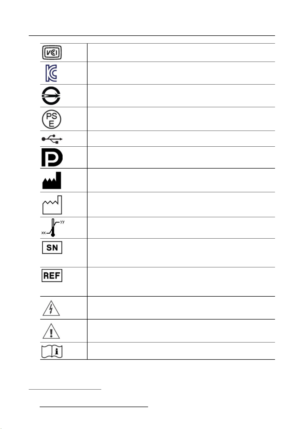
6. Important information
Indicates the device is approved according to the VCCI regulations
Indicates the device is approved according to the KC regulations
Indicates the device is approved according to the BSMI regulations
Indicates the device is approved according to the PSE regulations
Indicates the USB connectors on the device
Indicates the DisplayPort connectors on the device
Indicates the legal manufacturer
Indicates the manufacturing date
Indicates the temperature limitations1for the device to safely operate within specs.
Indicates the device serial number
Indicates the device part number or catalogue number
Warning: dangerous voltage
Caution
Consult the operating instructions
1. Values for xx and yy can be found in the technical specifications paragraph.
58 K5902105 (451920611791) MDSC-2232 25/08/2015
Page 61

or
6. Important information
Indicates this device must not be thrown in the trash but must be recycled,
according to the European WEEE (Waste Electrical and Electronic Equipment)
directive
Indicates Direct Current (DC)
Indicates Alternating Current (AC)
Stand-by
Equipotentiality
Protective earth (ground)
6.7 Legal dis c laimer
Disclaimer notice
Although every attempt has been made to achieve technical accuracy in this document, we assume no
responsibility for errors that may be found. Our goal is to provide you with the most accurate and usable
documentation possible; if you discover errors, please let us know.
Barco software products are the property of Barco. They are distributed under copyright by Barco NV or
Barco Inc., for use only under the specific terms of a software license agreement between Barco NV or
Barco Inc. and the licensee. No other use, duplication, or disclosure of a Barco software product, in any
form, is authorized.
The specifications of Barco products are subject to change without notice.
Trademarks
All trademarks and registered trademarks are property of their respective owners.
Copyright notice
This document is copyrighted. All rights
be reproduced or copied in any form or by any means - graphical, electronic, or mechanical including
photocopying, taping or information storage and retrieval systems - without written permission of Barco.
© 2015 Barco NV all rights reserved.
are reserved. Neither this document, nor any part of it, may
6.8 Technical specifica tio ns
Overview
Screen technology TFT AM LCD / S-IPS technology / LED backlight
Active screen size (diagonal) 31.55” (801 mm)
Active screen size (H x V) 698 x 393 mm (27.48” x 15.47”)
K5902105 (451920611791) MDSC-2232 25/08/2015 59
Page 62

6. Important information
Aspect ratio (H:V)
Resolution
Pixel pitch 0.364 mm
Color support 16.7 million (8-bit)
Color gamut 68% NTSC
Viewing angle (H, V) 178°
Luminance
Contrast ratio 1300:1 (typical)
LCD transition time (Rise time
Tr + Decay time Tf)
Tr = Gray to White
Tf = Gray to Black
White point
Doc clock
Gamma Native, 1.8, 2.0, 2.2, 2.4, DICOM
Backlight sensor Backlight stabilization
Front sensor
Housing color RAL 9003
Screen protection Anti-reflective tempered glass
Keyboard
Video input signals
(MDSC-2232 DDI)
16:9
2MP (1920 x 1080 pixels)
Maximum: 450 cd/m² (typical), with OSD brightness = 90
Default @ 6500K: 360 cd/m² stabilized (typical), with OSD brightness
=90
Average total 25 msec
Native: 10000K (typical)
Calibrated: 5600K, 6500K, 7600K, 9300K
165 MHz (maximum)
N/A
Capacitive 7-key touch keyboard (with enable/disable switch)
DVI-I Single Link (Digital & Analog – HDMI video support with HDCP)
DVI-D
Component Video RGBS / YPbPr (4xBNC)
S-video (4-pin Mini DIN)
Composite video (1xBNC)
Video output signals
(MDSC-2232 DDI)
Video input signals
(MDSC-2232 MNA)
Video output signals
(MDSC-2232 MNA)
3G-SDI (2xBNC)
DisplayPort (VESA std 1.1a)
DVI-D (output selectable from DVI-1 in, DVI-2 in)
S-video (4-pin Mini DIN)
Composite video (1xBNC)
3G-SDI (2xBNC)
DVI-I Single Link (Digital & Analog – HDMI video support with HDCP)
Component Video RGBS / YPbPr (4xBNC)
S-video (4-pin Mini DIN)
Composite video (1xBNC)
3G-SDI (1xBNC)
DisplayPort (VESA std 1.1a)
Nexxis fiber optic input
DVI-D (output selectable from DVI in, Nexxis)
S-video (4-pin Mini DIN)
Composite video (1xBNC)
3G-SDI (1xBNC)
60 K5902105 (451920611791) MDSC-2232 25/08/2015
Page 63

6. Important information
Video formats
Remote control
Power source requirements
for external power supply
Power source requirements
for display power input
Power supply DC output cable
length
Power management DVI-DMPM states supported
VGA & DVI : Up to 1920x1200 at 60Hz (reduced blanking)
Maximum pixel clock: 165MHz
Maximum Hor freq: 90kHz
Maximum Ver freq: 75Hz
Standard PAL and NTSC for S-Video, Composite and Component
Component YPbPr/ RGBS: HDTV - up to 1080i & 1080p
SDI Format Supported: 625/25 PA L, 525/29.97 NTSC, 1080i50,
1080i59.94, 1080i60, 720p50, 720p59.94, 720p60, 1080p50,
1080p59.94, 1080p60
SDI Compliance: SMPTE 425M (Level A), SMPTE 424M, SMPTE
292M, SMPTE 259M-C, SMPTE 296M, ITU-R BT.656, ITU-R BT.601
DisplayPort 1.1a: up to 1920 x 1200 60Hz
RS-232 (D-sub 9-pin)
100-240VAC, 50/60Hz (Medical Power supply, Class I, 2MOPP between
primary and secondary)
+24 VDC ±10% / 2.2 A (MDSC-2232 DDI)
+24 VDC ±10% / 3 A (MDSC-2232 MNA)
2.0 m (6.6 ft)
48W typical (MDSC-2232 DDI)Power consumption (nominal)
65W typical (MDSC-2232 MNA)
Power On state
Active-Off state
OSD languages English, French, German, Spanish, Italian
Dimensions display (W x H xD)777 x 472 x 92 mm (30.6” x 18.6” x 3.5”)
Dimensions power supply (W
xHxD)
Dimensions packaged (W x H
xD)
Net weight power supply
Net weight packaged
Mounting standard
Recommended modalities
Certifications • IEC 60601-1: 2012 Edition 3.1 (Medical electrical equipment – Part 1:
210 x 103 x 52 mm (8.27” x 4.06” x 2.05”)
970 x 625 x 200 mm (38.19” x 24.60” x 7.87”)
12.9 kg (28.4 lbs) (MDSC-2232 DDI)Net weight display
13.3 kg (29.3 lbs) (MDSC-2232 MNA)
1.2kg(2.65lbs)
19.0 kg (41.9 lbs) (MDSC-2232 DDI)
19.4 kg (42.7 lbs) (MDSC-2232 MNA)
VESA (100 x 100 mm, 200 x 100 mm)
Endoscopy, Laparoscopy, PACS, PM, US, CT, MR
General requirements for basic safety and essential performance)
• EN 60601-1: 2006 +A1:2013 (Medical electrical equipment”. Part 1:
General requirements basic safety and essential performance)
• ANSI/AAMI ES 60601-1: 2005/(R)2012 and A1:2012, C1:2009/(R)2012
and A2:2010/(R)2012 - Med. El. Equip., Part 1: general req. for basic
safety and essential performance.
• CAN/CSA-C22.2 No. 60601-1: 14 Medical Electrical Equipment - Part
1: General Requirements for Basic Safety and Essential Performance
(Harmonized with Ed. 3.1)
• Approvals/Marking: CE c-UL-us, DEMKO, PSE, KCC (CCC certification
is pending)
K5902105 (451920611791) MDSC-2232 25/08/2015 61
Page 64
6. Important information
Note PSE is available on PSU
• Electromagnetic Compatibility: EMC Medical EMC Standards:
IEC60601-1-2, EN55011/CISPR 11 (MDSC-2232 MNA: Class A,
MDSC-2232 DDI: Class B), FCC CFR47 part 15 & 18 (MDSC-2232
MNA: Class A, MDSC-2232 DDI: Class B)
• RoHS-2, REACH, WEEE compliant
• IP20 (IP45 monitor front side only)
Supplied accessories
Optional accessories Display pedestal (P/N K9302060A)
Operating temperature +10 ÷ +35 °C for performance, 0 ÷ +40 °C for safety
Storage temperature -20 ÷ +60°C
Operating humidity 10 ÷ 90% (non-condensing)
Storage humidity 5 ÷ 90% (non-condensing)
Operating altitude
Storage altitude
User Manual (English), other languages on CD
Mains cables: EU (CEBEC/KEMA) & US (Hospital grade UL)
External power supply
1 x 3m DVI Dual Link cable
3000 m max.
12000 m max.
Timings DVI-VGA
Item Name Pixel x Line Format Hor. Fr.
(kHz)
1 480i 720 x 487
2 480p59 720 x 480 480p 31,47 59,94 Y N
3 480p60 720 x 480 480p 31,5 60 Y N
4 576i 720 x 576 PAL I 15,625 50 Y N
5
576p 720 x 576 576p 31,25 50 Y N
6 720p29 1280 x 720 720p 22,48 29,97 Y N
7
720p30 1280 x 720 720p 22,5 30 Y N
8 720p50 1280 x 720 720p 37,5 50 Y N
9 720p59 1280 x 720 720p 44,96 59,94 Y N
10 720p60 1280 x 720 720p 45 60 Y N
11 1080i25 1920 x 1080 1080i 28,13 50 Y N
12 1080i29 1920 x 1080 1080i 33,72 59,94 Y N
13 1080i30 1920 x 1080 1080i 33,75 60 Y N
14 1080p29 1920 x 1080 1080p 33,72 29,97 Y N
15 1080p30 1920 x 1080 1080p 33,75 30 Y N
16 1080p50 1920 x 1080 1080p 56,25 50 Y N
17 1080p59 1920 x 1080 1080p 67,433 59,94 Y N
18 1080p60 1920 x 1080 1080p 67,5 60 Y N
19 DMT0660 604 x 480
20 DMT0672 604 x 480
21 DMT0675 604 x 480
22 DMT0685 604 x 480
23 DMT0856 800 x 600
24 DMT0860 800 x 600
NTSC
VGA
VGA
VGA
VGA
SVGA
SVGA
15,734 59,94 Y N
31,5 60 Y Y
37,86 72,808 Y Y
37,5
43,269 85,008 Y Y
35,16 56,25 Y Y
37,88 60,32 Y Y
Vert. Fr.
(Hz)
75
Hor.
Total
Vert.
Total
DVI
YY
VGA
62 K5902105 (451920611791) MDSC-2232 25/08/2015
Page 65

6. Important information
Item Name Pixel x Line Format Hor. Fr.
(kHz)
25 DMT0872 800 x 600
26 DMT0875 800 x 600
27 DMT0885 800 x 600
28 DMT1060 1027 x 768
29 DMT1070 1024 x 768
SVGA
SVGA
SVGA
XGA
XGA
48,08 72,19 Y Y
46,875
53,74 85,061 Y Y
48,4 60 Y Y
56,4 70 Y
Vert. Fr.
(Hz)
75
Hor.
Total
Vert.
Total
DVI
YY
(Diag.
mode)
2
30 DMT1075 1024 x 768
31 DMT1085 1024 x 768
32 DMT1175 1152 x 864
33
34
35
DMT1260G
DMT1275G
DMT1285G
1280 x 1024
1280 x 1024
1280 x 1024
36 DMT1660 1600 x 1200
37
38
CVR1460
CVT1460
1400 x 1050
1400 x 1050
XGA
XGA
XGA+
SXGA
SXGA
SXGA
UXGA
SXGA+
SXGA+
60
68,7 85 Y Y
67,5
64 60 Y Y
79,976 75,025 Y Y
91,1 85 Y Y
75
64,744 59,948 Y Y
65,32 59,98 Y Y
75
75
YY
YY
60 Y Y
(VESA)
39
40
41
CVR1660D
CVT1660D
CVT
1680 x 1050
1680 x 1050
1920 x 1200
WSXGA+1
WSXGA+2
WUXGA1
64,67 59,88 Y Y
65,29 59,95 Y Y
74,038 59,95 Y Y
42 IBM 640 x 350 31,5 70 800 449 Y
(Diag.
2
mode)
43 VESA 640 x 350 37,9 85 832 446 Y Y
44 VESA 640 x 400 24,8 56,3 848 440 N Y
45 IBM 640 x 400 31,5 70,0 800 449 Y
(Diag.
2
mode)
46
VESA
640 x 400 37,9 85,0 832 446 Y Y
VGA
Y(Diag.
mode)
2
N
N
Timings Comp - SOG
Item Name Pixel x Line Format Hor. Fr.
(kHz)
1 480i 720 x 487
NTSC
15,734 59,94 Y Y
2 480p59 720 x 480 480p 31,47 59,94 Y Y
3 480p60 720 x 480 480p 31,5 60 Y Y
4 576i 720 x 576 PAL I 15,625 50 Y Y
5
576p 720 x 576 576p 31,25 50 Y Y
8 720p50 1280 x 720 720p 37,5 50 Y Y
9 720p59 1280 x 720 720p 44,96 59,94 Y Y
10 720p60 1280 x 720 720p 45 60 Y Y
11 1080i25 1920 x 1080 1080i 28,13 50 Y Y
12 1080i29 1920 x 1080 1080i 33,72 59,94 Y Y
13 1080i30 1920 x 1080 1080i 33,75 60 Y Y
14 1080p29 1920 x 1080 1080p 33,72 29,97 Y Y
2. OSD Smart Video set to “Diagnostic”
K5902105 (451920611791) MDSC-2232 25/08/2015 63
Vert. Fr.
(Hz)
Hor.
Tota l
Vert.
Total
SOG RGBS /
YPbPr
Page 66

6. Important information
Item Name Pixel x Line Format Hor. Fr.
(kHz)
15 1080p30 1920 x 1080 1080p 33,75 30 Y Y
16 1080p50 1920 x 1080 1080p 56,25 50 Y Y
17 1080p59 1920 x 1080 1080p 67,433 59,94 Y Y
18 1080p60 1920 x 1080 1080p 67,5 60 Y Y
Vert. Fr.
(Hz)
Hor.
Tota l
Vert.
Total
SOG RGBS /
Timings SDI
Item Name Pixel x Line Format Hor. Fr.
(kHz)
1 480i 720 x 487 NTSC 15,734 59,94 Y Y
4 576i 720 x 576 PAL I 15,625 50 Y Y
8 720p50 1280 x 720 720p 37,5 50 Y Y
9 720p59 1280 x 720 720p 44,96 59,94 Y Y
10 720p60 1280 x 720 720p 45 60 Y Y
11 1080i25 1920 x 1080 1080i 28,13 50 Y Y
12 1080i29 1920 x 1080 1080i 33,72 59,94 Y Y
13 1080i30 1920 x 1080 1080i 33,75 60 Y Y
14 1080p29 1920 x 1080 1080p 33,72 29,97 Y Y
15 1080p30 1920 x 1080 1080p 33,75 30 Y Y
16 1080p50 1920 x 1080 1080p 56,25 50 Y Y
17 1080p59 1920 x 1080 1080p 67,433 59,94 Y Y
18 1080p60 1920 x 1080 1080p 67,5 60 Y Y
Vert. Fr.
(Hz)
Hor.
Total
Vert.
Tota l
SDI
(Ypb)
YPbPr
RGBS /
YPbPr
SDI Standard Compliance:
SMPTE 425M (level A), SMPTE 424M, SMPTE 292M, SMPTE 296M, ITU-R BT.656, ITU-R BT.601
SDI Video Sampling:
Y Cb Cr 4:2:2
64
K5902105 (451920611791) MDSC-2232 25/08/2015
Page 67

Dimensions
472472
6. Important information
777 92
698
200
100
100186 393
Image 6- 2
6.9 Open source license informati
288.5
on
Open source license information
This product contains software components released under an Open Source license. You acknowledge
living up to the conditions of each separate Open Source Software license.
A list of the Open Source Software components used is available in the applicable EULA, through the “My
Barco” section of the Bar
co website or through other (online) means.
Copyright on each Open Source Software component belongs to the respective initial copyright holder,
each additional contributor and/or their respective assignee(s), as may be identified in the respective Open
Source Software documentation, source code, README file, or otherwise. You shall not remove or obscure or otherwise alter the respective copyrights.
EACH SEPARATE OPEN SOUR
CE SOFTWARE COMPONENT AND ANY RELATED DOCUMENTATION ARE PROVIDED "AS IS" WITHOUT EXPRESS OR IMPLIED WARRANTY INCLUDING, BUT NOT
LIMITED TO, THE IMPLIED WARRANTIES OF MERCHANTABILITY AND FITNESS FOR A PARTICULAR PURPOSE. IN NO EVENT SHALL THE COPYRIGHTHOLDER OR ANY OTHER CONTRIBUTOR
BE LIABLE FOR DIRECT, INCIDENTAL, SPECIAL, EXEMPLARY OR CONSEQUENTIAL DAMAGES,
EVEN IF ADVISED OF THE POSSIBILITY OF SUCH DAMAGES, HOWEVER CAUSED AND ON ANY
K5902105 (451920611791) MDSC-2232 25/08/2015
65
Page 68

6. Important information
THEORY OF LIABILITY. MORE INFORMATION/DETAILS IS TO BE FOUND IN EACH SPECIFIC OPEN
SOURCE LICENSE.
With respect to GPL, LGPL or similar licenses with regard to corresponding source code access and
automatic license terms applicability:
• You acknowledge living up to the conditions of each such specific applicable Open Source Software
license. You are responsible for your own additions, changes or modifications without any recourse
or claim towards Barco whatsoever. You further acknowledge that any such additions, changes or
modifications may impair the ability of Barco – at Barco’s sole discretion - to continue to provide service, warranties, software updates, fixes, maintenance, access or such similar abilities, without any
recourse or claim towards Barco whatsoever.
• Barco offers to provide the corresponding source code, and shall make the corresponding source c
available to you via email or download link, except where the applicable license entitles you to require
Barco to provide you the corresponding source code on a tangible medium, in which case Barco will
charge you for the actual costs of performing such distribution, such as the cost of media, shipping
and handling. You may exercise this option upon written request to Barco N.V, attn. legal department,
President Kennedypark 35, 8500 Kortrijk (Belgium). This offer is valid for a period of three (3) years
from the date of the distribution of this product by Barco.
ode
66
K5902105 (451920611791) MDSC-2232 25/08/2015
 Loading...