

Page 1
RHDM-1701
16.5" - LCD Broadcast Monitor
User manual
K5960051-01
Page 2

Intentionally left blank
2 Barco - RHDM-1701 - User manual
Page 3
1 Introduction
1.1 Customer notice
Thank you for buying Barco!
Barco is a world leader in display and visualization solutions. We are convinced that you will enjoy
our products.
1.2 Change record
Revision Date Description
00 April 2010 Initial release
01 July 2010 Update for software V3.04
Introduction
Barco - RHDM-1701 - User manual 3
Page 4

Introduction
1.3 Contents of the user manual
1.3.1 Introductory notes on the content
The user manual is divided in different sections. The sections that are relevant to the reader may
depend on the readers’ experience level.
Get an image on the screen in 5 minutes: After reading the important notices and safety
introduction in the chapter “Introduction”, the information provided in the chapter “First operation”
will guide the user through the process of switching on and viewing an input signal on the display
unit.
First reconnaissance with the display unit: A chronological reading of the user manual is
probably the most satisfying way for users who have not used the display unit before. Especially the
chapter “First operation” and the chapter “How to” will give the user a good feel for the basic
operations and the capabilities of the display unit.
Finding out “how to” perform a frequently used operation: A dedicated chapter “How to” is
made for the most frequent operations the user would like to execute. It will help the user to solve
the question quickly, since it is built up as a non chronological guide.
Basic knowledge of the display unit, expert question: The chapter “full functionality
description” contains all there is to know about the display unit. The information is ordered in a
chronological way.
Technical details: Check the “Addendum” for detailed and technical information on the display
unit.
Trough-out the manual, the reader may wonder about the use of a specific term. The frequently
used terms are gathered in the chapter “Terminology” for the readers’ convenience.
1.3.2 Structure of the user manual
Chapter 1: Introduction
The introduction contains all general information related to the product, including “About the
product”, “Important notices” and “Safety precautions”.
Chapter 2: First operation
The basic operations of the display unit are explained in this chapter.
Chapter 3: How to
Frequently used procedures and/or features are described in this chapter. This is a good place to
start for users who want to learn how the basic controls work.
Chapter 4: Full functionality description
4 Barco - RHDM-1701 - User manual
Page 5

Introduction
All options and possibilities are listed in this chapter. This is an extensive and complete list of all
features.
Chapter 5: Video signal processing
Describes details related to the video signal processing of the display unit.
Chapter 6: Terminology
The terminology used in this manual is explained in detail in this chapter. This allows the beginner
and the expert to fall back on a consistent naming convention used throughout this manual.
Chapter 7: Addendum
The Addendum is quite extensive and includes the more technical parts of information that are
useful for system integrators and people who want to know more about the technical specifications
of the display unit.
Chapter 8: List of abbreviations
Chapter 9: Table of contents, list of figures and list of tables
Barco - RHDM-1701 - User manual 5
Page 6

Introduction
1.4 About the product
The RHDM-1701 is a reliable grade-1 reference monitor for color critical applications in the
broadcast and post-production markets, such as:
• camera control
• program and distribution monitoring
• signal QA (Quality Assurance)
• technical room
• color grading
• DI (Digital Intermediate)
The RHDM-1701 reference monitor brings value of trusted reference colors, no calibration
maintenance for a long period, and image quality comparable to CRT.
On top of that, the user-friendly interface and ease of use are unparalleled in similar LCD monitors.
On the feature level, the color accuracy and stability with time and temperature, perfect grey scale
representation, deep and correct blacks, motion handling with scanning backlights and a myriad of
other features give large benefits to professionals active in these markets.
The Key features of the display unit are:
LCD panel
• 16.5” (41,9cm) diagonal
• 1920x1080
• 10 bit panel
• Typical contrast 1000:1
• Barco guarantees the delivery of a RHDM-1701 monitor equipped with an LCD panel selected
zero dot defects at sparkle mode. Sparkle mode is when the brightness of a dot is more than
16% at black.
Optical properties
• Wide gamut LED backlight
Processing of input signals
• 48 bit color processing (16 bit per color)
• 96-120 Hz native LCD driving
• Genlock and frame sync
• Quantified latency
• Scanning backlight functionality
6 Barco - RHDM-1701 - User manual
Page 7

Calibration and stability
• Compliant with following color standards:
EBU 3213
SMPTE C
ITU BT.709
xvYCC
sRGB
Adobe
DCI
• Selection of different opto-electric transfer functions (‘gamma’)
Rec.709
xvYCC
Pure gamma
Extended gamma
sRGB
SMPTE 240M
• Factory cross-talk calibration
• Thermal sensor circuit for LED stabilization with temperature
• Embedded spectrometer for overall color stabilization over time
• Embedded special sensors for LED uniformity and color stabilization over time
Modular input configuration (4 slots)
• Slot 1 - 1 SDI input board (standard)
• Slot 2 – 1 SDI input board (optional)
• Slot 3 – future option (DVI)
• Slot 4 – future option (DVI)
SDI module specifications
• Possible inputs:
2 x SDSDI
2 x HDSDI
2 x 3Gb/s (option)
Combination of 2 signals out of: SDSDI, HDSDI or 3Gb/s (option)
1 Dual Link (option)
• Outputs: 2 loop-through outputs
Introduction
Barco - RHDM-1701 - User manual 7
Page 8

Introduction
Control
• Control panel with main functions and hot keys
• Ethernet interface with web server
• RS485 serial and parallel control or Tally/UMD
• USB: host, peripheral and support of mass storage devices, mouse, etc…
Feature packs and options
• The RHDM-1701 comes in different flavors. Depending on the specific applications that are targeted by the user, different feature packs can be selected. Depend ing on the feature pack, additional options can be available.
• Broadcast – RHDM-1701/B: standard feature pack
Accepts SD and HD-SDI timings (2 inputs with loop-through outputs)
Selectable color space (EBU, SMPTE C, Rec.709 and Native), color temperature and gamma
Configurable aspect ratio and safe area markers
Standard controls (picture, background, saturation, hue, color channel selection, mono-
chrome, input selection, aspect ratio and picture size, interlace mode)
• Post production – RHDM-1701/P has all features of the B version plus:
Custom R, G, B primaries (in x,y)
Accepts Dual Link HD-SDI timings
Accepts 3Gb/s SDI timings
8 Barco - RHDM-1701 - User manual
Page 9
1.5 Read carefully
Introduction
IMPORTANT
Please read the important notices and safety precautions, mentioned in the following paragraphs, carefully. They
provide essential juridical and technical information about the purchased product.
:
1.6 Important notice
1.6.1 Notation convention
Following notations are applicable to this manual and should be respected throughout the manual.
WARNING
Warnings – presented in this manual, provide information, which if not adhered to, may result in personal injury or
death.
CAUTION
Cautions – presented in this manual, provide information, which if not adhered to, may result in damage to the
equipment.
NOTE
Notes – presented in this manual, provide information, which emphasize points, significant to understand and
operate the unit.
:
:
:
IMPORTANT
Important – presented in this manual, provide information, which is important to highlight.
:
1.6.2 Copyright
© Barco n.v., All rights reserved.
Barco - RHDM-1701 - User manual 9
Page 10

Introduction
The information contained herein is Barco confidential information. No part of the information
contained herein may be disclosed outside of the organization of the recipient, its sub-contractors,
and customers in any form or by any means and/or stored in a database or retrieval system without
the prior written consent of Barco.
1.6.3 Technical accuracy notice
Although every attempt has been made to achieve technical accuracy in this document, we assume
no responsibility for errors that may be found. Our goal is to provide you with the most accurate
and usable documentation possible; if you discover errors, please let us know.
1.6.4 Technical specifications notice
The technical specifications mentioned in this manual shall under no circumstances be used as
proof or item of evidence.
Only the technical specifications defined in the Barco technical specifications document (which is
not part of this manual) can be used as a base for contract negotiations.
1.6.5 Federal Communication Commission (FCC) notice
This equipment has been tested and found to comply with the limits of an FCC class (refer to the
technical specifications of the specific unit for more details about the corresponding class). These
limits are designed to provide reasonable protection against harmful interference when the
equipment is operated in a commercial environment. This equipment generates, uses and can
radiate radio frequency energy and, if not installed and used in accordance with the instruction
manual, may cause harmful interference to radio communications. Operation of this equipment in a
residential area is likely to cause harmful interference in which case the user will be required to
correct the interference at his own expense.
1.6.6 Warranty
During the warranty period, Barco n.v. will do all repairs free of charge (material and
labor). The faulty parts or units have to be shipped freight prepaid to a Barco n.v.
regional service center. Barco n.v. will pay the freight charges when the repaired
parts are shipped back to the customer's site.
Damage of equipment due to improper use or negligence of the safety precautions
incorporated in this manual are not covered by this warranty.
10 Barco - RHDM-1701 - User manual
Page 11
Introduction
IMPORTANT
Opening the cover of the display unit voids the warranty.
The warranty does not include the following:
• Any hardware or software item procured from a source other than Barco n.v. or their official
agent or distributor and integrated by Customer or a third party into Barco n.v. supplied equipment.
• Any host or system configuration not explicitly supported by Barco n.v..
• Consumables such as projector lamps, dust filters, ...
• All software installed on the system, whether they are acquired from Barco n.v. or a third party.
An exception is made for software delivered by Barco n.v. that would prove to be a cause for the
malfunctioning of the hardware covered under this Agreement.
• If any payment remains outstanding from the Purchaser to the Seller.
• Normal wear and tear, use under circumstances exceeding specifications, abuse, unauthorized
repair or alteration, lack of proper maintenance.
• In the particular case of LCD displays, to the case of image retention phenomena (shadows, dark
lines and other image artifacts), that may result from a usage outside of the specification.
• Any failures resulting from an accident, negligence (such as but not limited to removing or deleting system files & licensed software product files), misuse, circuit failure or any change, damage
due to fire, water, thunder or lightning, power failure or fluctuation, disruption of communication
lines or due to force majeure, or any reason foreign to the equipment.
• Any specific services or procedures, asked for by the Customer, related to verification of repaired
equipment.
• If several failures occur which are excluded from warranty due to circumstances such as fire and
if Barco n.v.’s understanding that these circumstances may result in damage to other hardware
under agreement, then Barco n.v. is entitled to terminate the contract. No fees will be paid back
by Barco n.v. in this case. Inspection of equipment will be required prior to the continuation of
this Agreement; the same terms and conditions as for the inspection prior to the contract apply.
:
1.6.7 Trademarks
Brand and product names mentioned in this manual may be trademarks, registered trademarks or
copyrights of their respective holders. All brand and product names mentioned in this manual serve
as comments or examples and are not to be understood as advertising for the products or their
manufactures.
Barco - RHDM-1701 - User manual 11
Page 12
Introduction
1.6.8 Open source license
This product contains software components released under an Open Source license. A copy of the
source code is available on request by contacting your sales representative.
See appendix A for details.
1.6.9 WEEE
In order to avoid dissemination of toxic substances in the environment and to diminish the pressure
on natural resources, we encourage you to use the appropriate take-back systems. Those systems
will reuse or recycle most of the materials of your end-of-life equipment in a sound way.
The crossed-out wheeled bin symbol invites you to use those systems. If you need more
information about the collection, reuse and recycling systems, please contact your local or regional
waste administrator or Barco (www.barco.com).
12 Barco - RHDM-1701 - User manual
Page 13
1.7 Safety precautions
1.7.1 Earthing
Introduction
WARNING
The display unit must be earthed correctly. Verify that the power cable is plugged into a standard 3-pin power
outlet which is effectively earthed. When using extension cords, make sure that they contain a grounded
connection. If in doubt, contact a qualified electrician. Ignoring this warning may lead to persona l inju ry or death.
:
1.7.2 Electrical warnings and cautions
• Do not power the unit with other input sources as specified in the technical specifications.
• Always power-down the unit before disconnecting the power cable.
• Unplug the display unit from the power source when not in use.
IMPORTANT
Immediately unplug if:
• the power supply cord is damaged.
• the unit has been dropped or the cabinet is damaged.
• the unit does not operate normally by following the operation instructions.
WARNING
Do not remove the cover without authorization. Removal of the cover by non-qualified personnel can cause
personal injury.
:
:
1.7.3 Environmental cautions
• Do not use the display unit in a dusty or damp room.
• Do not submit the display unit to heavy shocks and/or vibrations.
• Do not cover the display unit while in operation to avoid overheating.
• Do not expose to direct sunlight.
Barco - RHDM-1701 - User manual 13
Page 14

Introduction
• Do not use the display at extreme limits of temperature and humidity range. Storage and operating limits are specified in the technical specifications of the unit.
1.7.4 Requirement for dusty environments
The room in which the display unit is installed and operational must be dust-free. The room must
comply with a dust class of 8 or better according to ISO14644-1. If the room in which the display
unit is installed does not comply with the dust class stated above, please contact Barco to discuss
possibilities to protect the display unit against dust.
NOTE
:
All construction, reconstruction, decoration activities must be completed before the installation and operation of the
product.
1.7.5 LCD screen
• Do not apply pressure on the surface of the screen. If ‘waves’ are visible on the screen below the
pressing object (e.g. finger), the pressure is already too high and the LCD may already break
under these circumstances.
• Do not hit the LCD screen with hard objects.
• Do not rub the LCD screen with rough materials.
• Do not touch the LCD screen with hard materials. Hard materials can cause scratches on the surface of the LCD screen. Examples of hard material are: fingernails, pencils, pens and styluses,
wooden, plastic or metal objects.
• While moving the display unit manually, hold the LCD screen away from your body to avoid
scratching the LCD screen.
• Do not paste or stick objects with glues and/or adhesive tapes on the LCD screen.
• Wipe off water droplets or oil immediately. Ignoring this precaution could lead to staining and/or
discoloration of the LCD screen.
• Do not expose the LCD screen to direct sunlight.
1.7.6 Cover
• Do not place objects on the cover.
• Do not spill fluids over the cover or the LCD screen.
• Do not push objects into ventilation openings of the display unit.
14 Barco - RHDM-1701 - User manual
Page 15
1.7.7 Hazardous materials
Introduction
WARNING
The LCD panel is composed of multiple layers of glass and protective glass with a small amount of liquid in
between. Rough handling or dropping can cause the LCD panel to break. If any part of the skin or body comes in
direct contact with the liquid, immediately wash the affected areas with plenty of water for at least 15 minutes. If
any symptoms are present after washing, get medical care.
:
1.7.8 Specific handling precautions
• Do not power the unit with other input sources as specified in the technical specifications:
AC power source: 90-264 Vac, 47-63 Hz
• Do not push objects into ventilation openings of the display unit.
Barco - RHDM-1701 - User manual 15
Page 16
First operation
2 First operation
2.1 Unpacking, installation and cabling
For unpacking, installation and cabling please refer to:
• The quick installation sheet
• The section “Installation” in the Addendum
2.2 Overview locations for operation
1
2
3
4
5
6
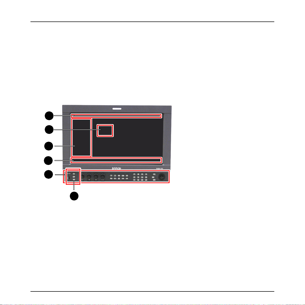
Figure 1: Overview of operational controls, indicators and OSD functionalities
Different operation interfaces:
1) Status bar
2) OSD menu
3) Toolbox
4) Under Monitor Display bar / Picture Adjustment bar
5) Control panel
6) Indicator lights
16 Barco - RHDM-1701 - User manual
Page 17
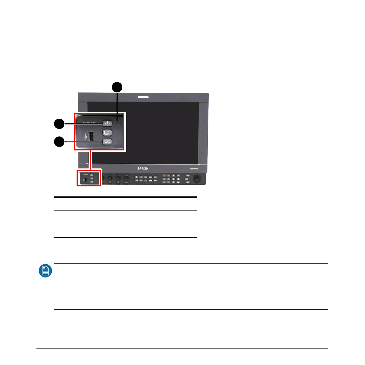
2.3 Switch on the display unit
This section is intended for a user who has no experience with the display unit and describes the
standard settings that are necessary to get the display unit up and running. Please check the
chapter with the “full functionality description” to find detailed information on each part and each
function of the display unit.
2
1
3
First operation
1 Standby/Power LED (green or orange)
2Fault LED (red)
3 Calibration LED (orange or red)
Figure 2: Overview indicator lights
NOTE
:
The display unit has a certain delay time between powering up and displaying an image on the screen (20
seconds). The delay time originates from several internal checks and calibrations that are performed to guarantee
the correct display of the image. When in doubt about the status of the display unit, please read the
troubleshooting in the addendum.
Barco - RHDM-1701 - User manual 17
Page 18
First operation
• Check the indicator lights to verify the status of the display unit. When no indicator lights
are lit, check the installation instructions in the addendum to power up the display unit (check if
the power switch at the back is switched on).
Standby/Power LED = green: Display unit is switched on – no further actions are necessary.
Standby/Power LED = orange: Display unit is switched on (soft standby) – the panel and
backlights are switched off. Press (
backlights.
Standby/Power LED = white: Display unit is switched off (hard standby) – press () on
the control panel to switch the display unit on. The Standby/Power LED will light up green.
)
on the control panel to activate the panel and
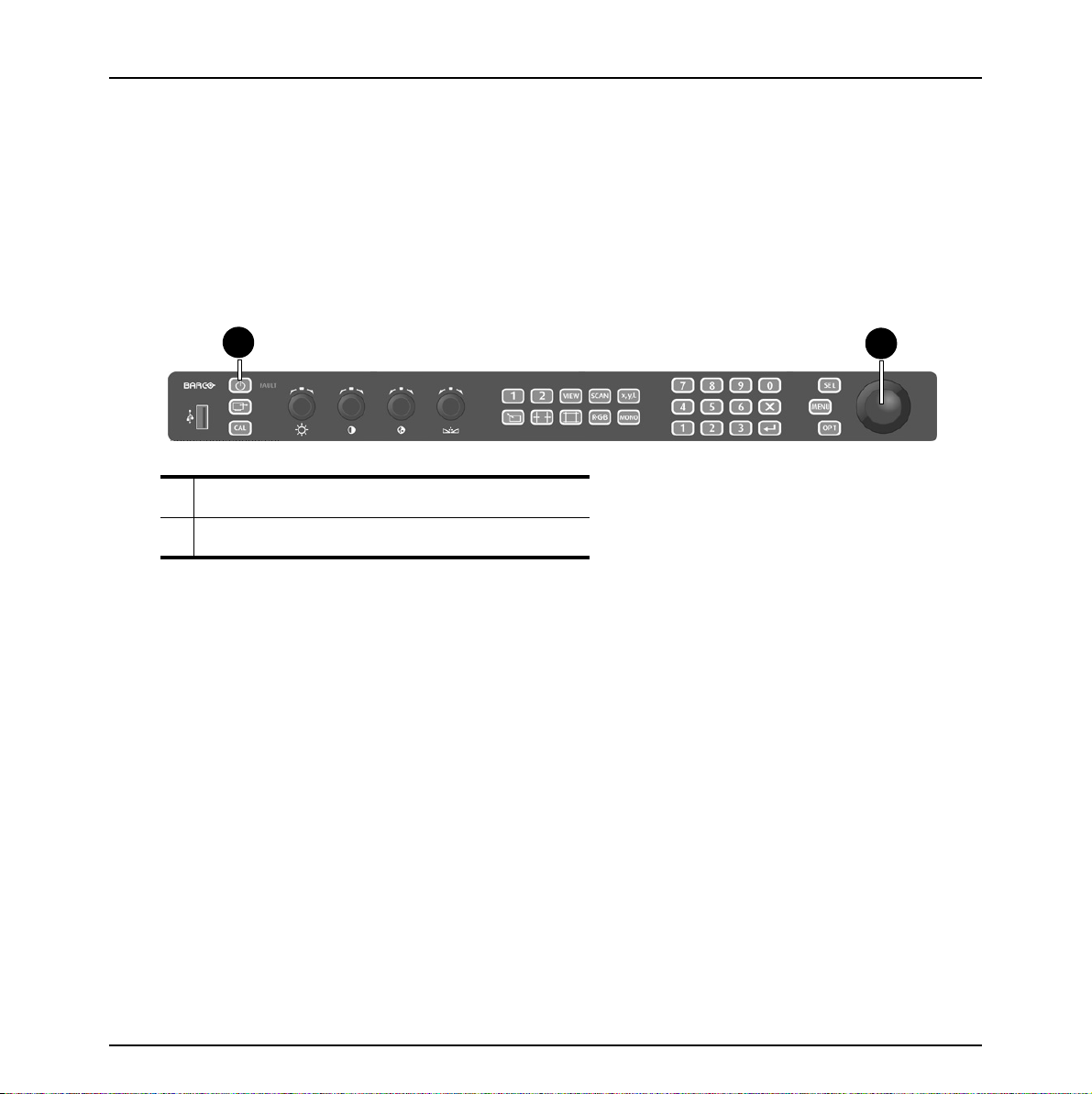
1
1 Power button
2Track ball
Figure 3: Control panel – power button
2
18 Barco - RHDM-1701 - User manual
Page 19
2.4 How to register the display unit
During the first 200 hours of operation, all features on the display are enabled, so you are able to
use your display straight out of the box.
In order to continue using your product after that initial grace period, you need to install a valid
license file (which enables the software configuration you have purchased). The license file can be
obtained from our website (as explained in this document). Of course you can install a license file
before the grace period has passed, which will immediately limit the features to the ones you have
purchased.
In the box of each display unit there is an envelope with a license sheet for the product flavor you
have purchased (B or P). If you have purchased any optional ‘feature packs’, there are also
envelopes with license information for each feature pack.
The product, the license sheets for the basic flavor (B or P) and any additional license sheet, all
have their own unique pincodes that have to be registered on our website, before activating your
product.
Overview of the basic steps:
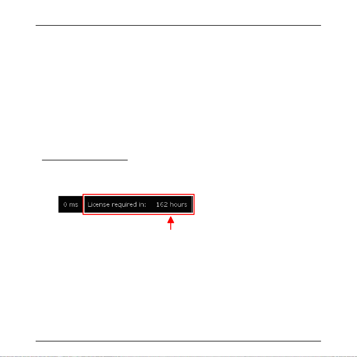
1. Switch on the display unit. Consult the installation section of this manual to install the display
unit. What happens after start-up depends on the license grace period.
• If the license grace period is still in effect, you are able to use the monitor and all its features.
The remaining grace period is shown in the top right corner.
First operation
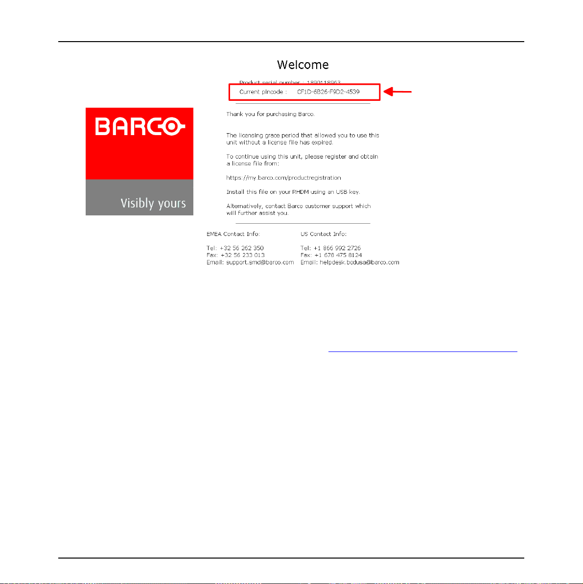
To register the unit on the website, you will need the current pincode. To obtain it, press Menu
and scroll down to the License submenu. The current pincode is displayed there.
Barco - RHDM-1701 - User manual 19
Page 20
First operation
• If the grace period has expired, you will see the “Welcome message” with instructions on the
screen. Write down the pincode of the display unit that is displayed on the screen, you will need
to register it on the website.
20 Barco - RHDM-1701 - User manual
Page 21
First operation
2. Collect the envelope(s) containing a software license sheet with a pincode from the box
of the display unit.
3. Register your products and licenses by entering their pincodes on the personalized
webpage to obtain license files for your products (https://my.barco.com/productregistration/
In case my.barco.com is not available, please contact Barco service (see contact info mentioned
in the above screenshot)
4. Download the license file from the product registration website and upload it to your
product using a USB key
Barco - RHDM-1701 - User manual 21
).
Page 22
First operation
display
PINcode
Register at
my.barco.com
USB
Registered
monitor
license
file
License
PINcode
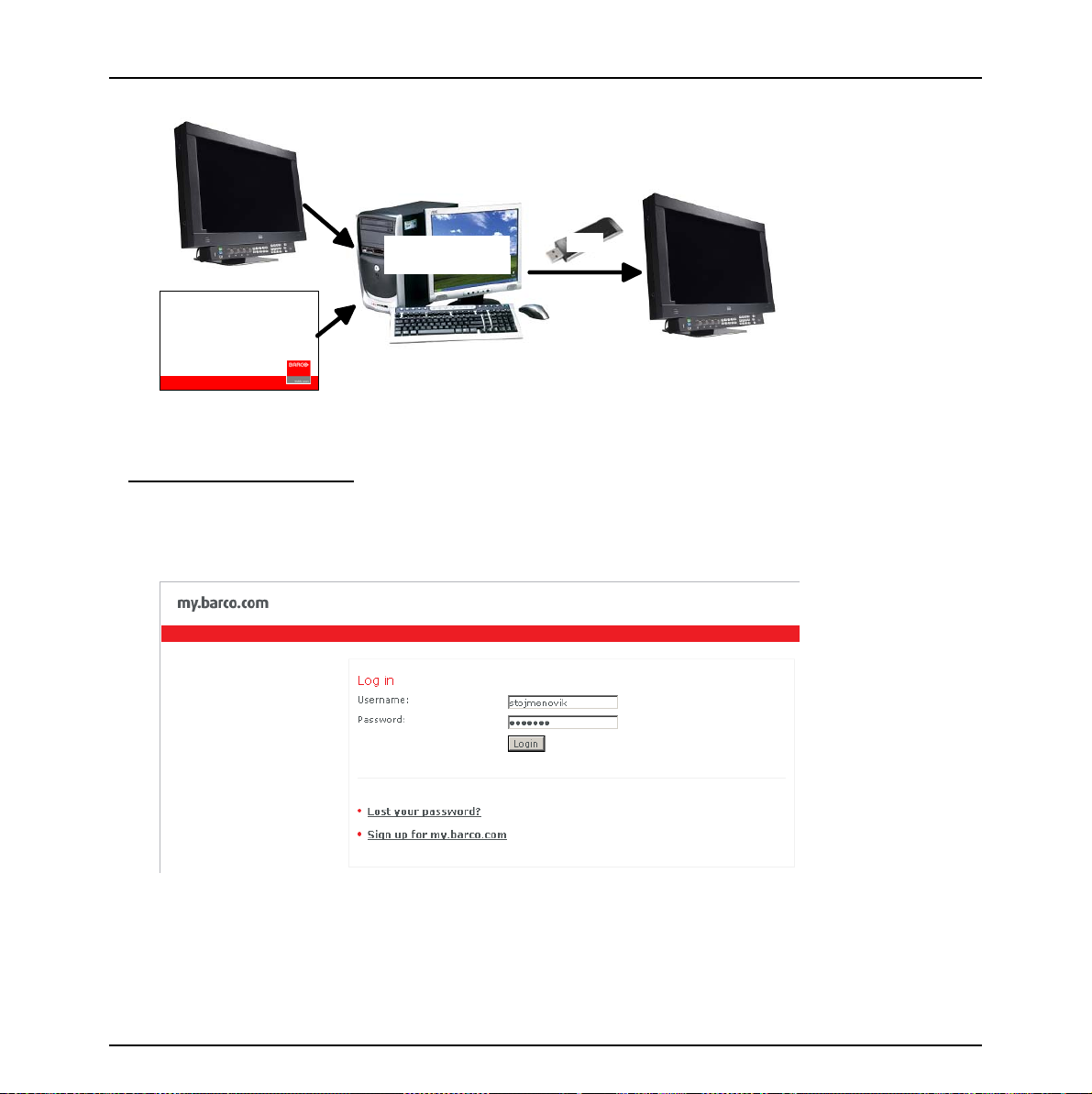
Figure 4: Schematic overview of the registration process
Step-by-step procedure:
1Login
• If you already have an existing my.barco.com account, please click ‘Login’ and enter your existing user name and password to proceed with the login.
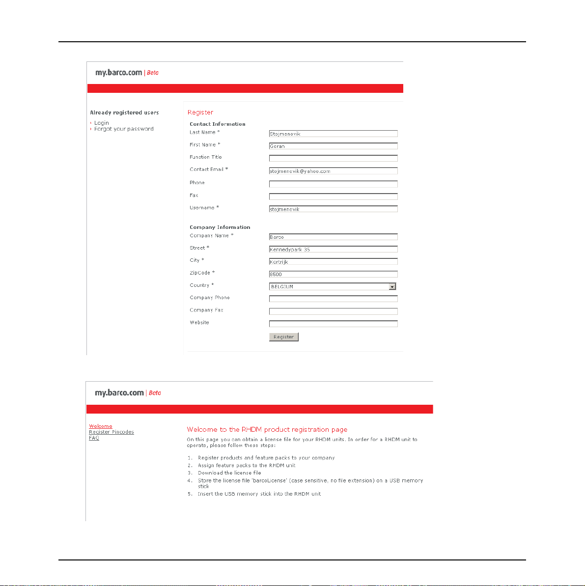
• Otherwise if you are a new customer, please sign up to open a my.barco.com account. (This step
is done only once)
22 Barco - RHDM-1701 - User manual
Page 23
First operation
• The welcome screen appears. Click on the left tab ‘Register Pincodes’.
Barco - RHDM-1701 - User manual 23
Page 24
First operation
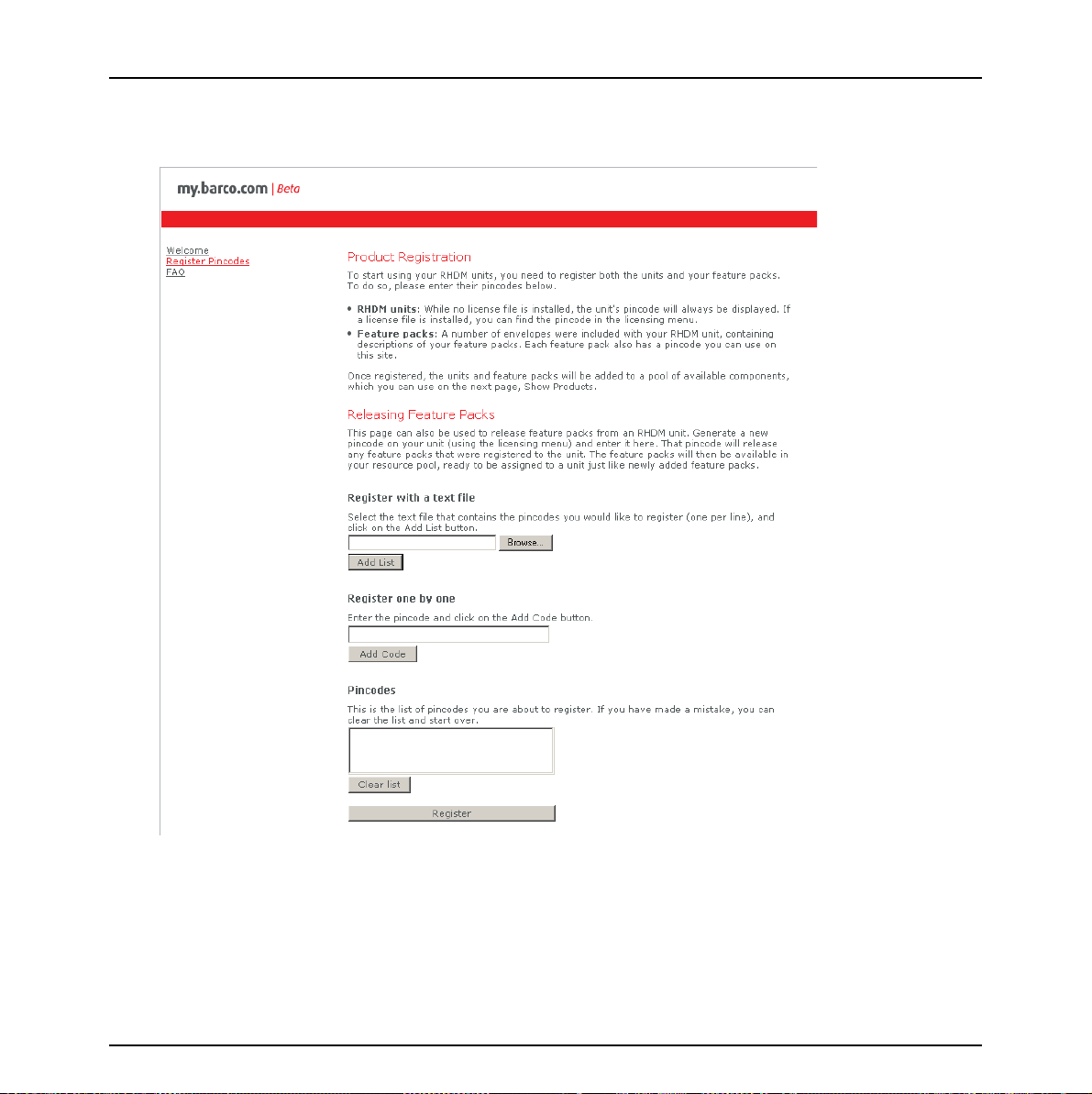
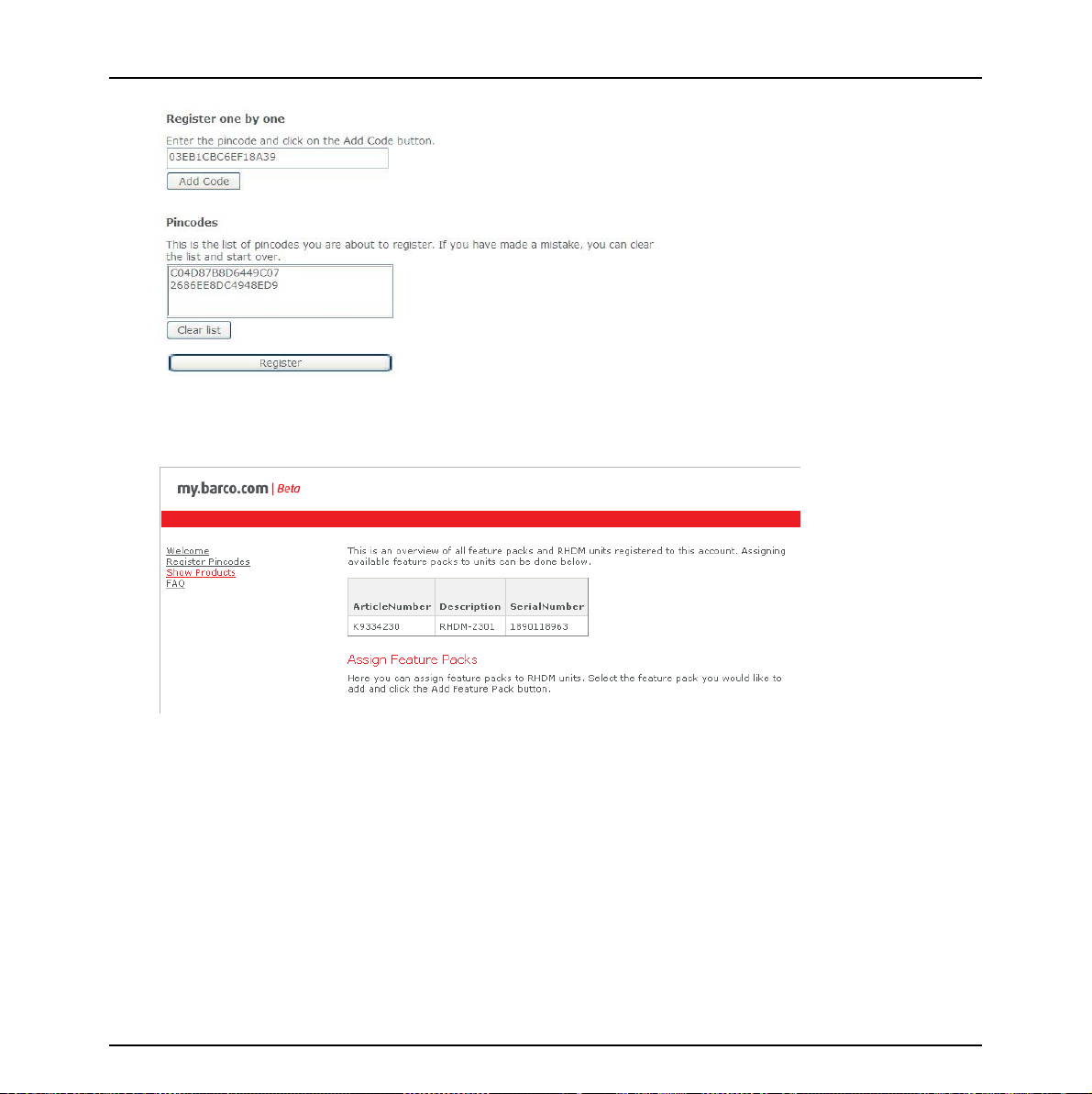
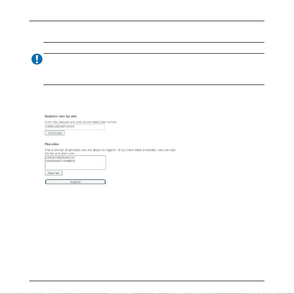
5. Register Pincodes
• Add all pincodes of the new products and licenses to be registered
• When adding codes, the pincode appears in the list at the bottom of the window
24 Barco - RHDM-1701 - User manual
Page 25
First operation
• When done entering, click on ‘Register’.
• A new page (“Show Products”) will open with a list of all entered pincodes at the top:
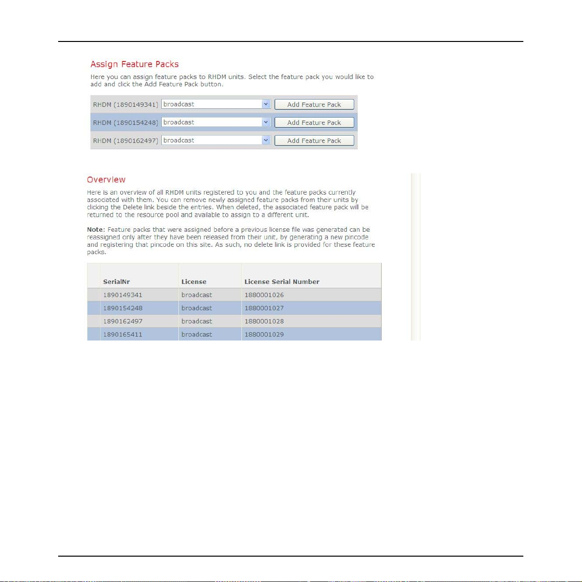
6. Assign licenses to products
• In the middle of the “Show Products” page, you have the possibility to assign a license (feature
pack) to the monitor of your choice. Select the license you would like to assign to that monitor
and click ‘Add Feature Pack”.
Barco - RHDM-1701 - User manual 25
Page 26
First operation
• There is an overview of the assigned licenses at the bottom of the page.
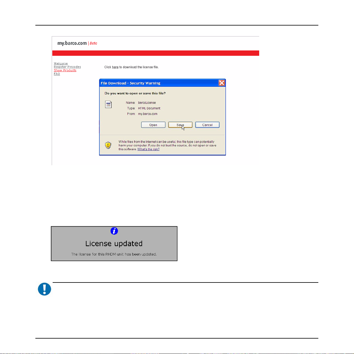
7. Get License File
• If you agree with this assignation, click on ‘Get License File’
• Following page with a link appears. Click the link ‘here’ and save the file on location of your
choice.
26 Barco - RHDM-1701 - User manual
Page 27
First operation
8. Upload license file to monitors
• Copy the obtained license file to an USB stick, but make sure that the file name is ‘barcoLicense’
(no extension, case sensitive)
• There is only one license file for all monitors that have been registered with this procedure. Plug
the USB stick in each monitor that has been registered and wait 1-2s. until it becomes activated.
• The display unit will recognize the license file automatically. The following message appears
when the update is successful. The display unit should function immediately.
IMPORTANT
:
Important note: Only license files with a filename “barcoLicense” (case sensitive, no extensions) will be recognized
by the RHDM. If you obtain a file that has additional information in its name (such as customer reference, serial
Barco - RHDM-1701 - User manual 27
Page 28
First operation
number etc), then rename the file to barcoLicense for purposes of license upload, and keep a copy of the original
file for your records.
IMPORTANT
Important note: Verify that the USB stick used to install the license file does not contain a RHDM softwa r e pa ck a g e
(xxx.deb) or a 3D LUT file (3d.lut) in its root. Software updates always have priority and will prevent the license
from being installed.
9. Troubleshooting
• If the registration process produces an error, check if the license codes were entered correctly. If
the problem persists, contact Barco.
• You might by mistake assign the wrong license to a monitor with a particular S/N. (e.g. a monitor that is installed at a certain position). This can be corrected.
:
First, upload the wrong license file to the monitor.
Generate a new pincode via the monitor’s OSD (see following section).
Register this pincode on the website, as explained previously.
The website will ‘release’ that particular monitor and the (wrong) license previously associ-
ated with it
Assign that license to the correct monitor.
28 Barco - RHDM-1701 - User manual
Page 29
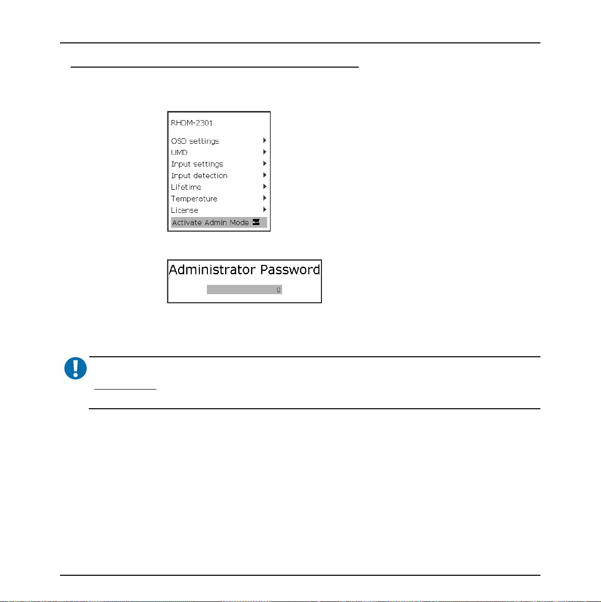
How to change the license assigned to your display unit:
• Activate the “Admin mode” that you can find in the main menu
Press (“Menu”) to open the OSD menu
Provide the administrator password:
Administrator password is “313329”
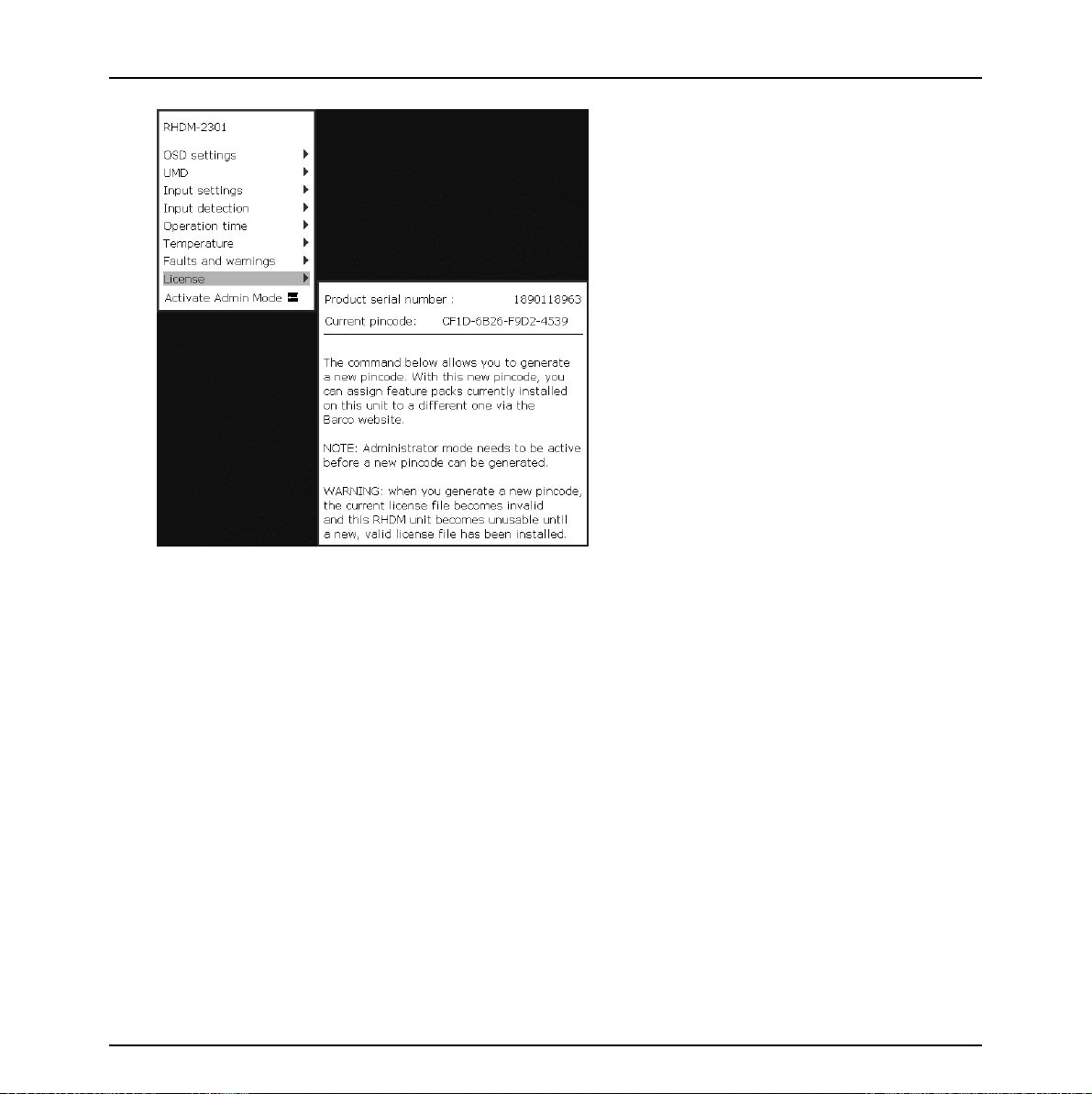
• Click on “Generate new Pincode” in the “License” OSD menu:
First operation
IMPORTANT
Important note: Do not generate a new pincode unless you plan to install new licenses on your product. Generating
a new pincode will disable the feature packs on your product!
:
Barco - RHDM-1701 - User manual 29
Page 30
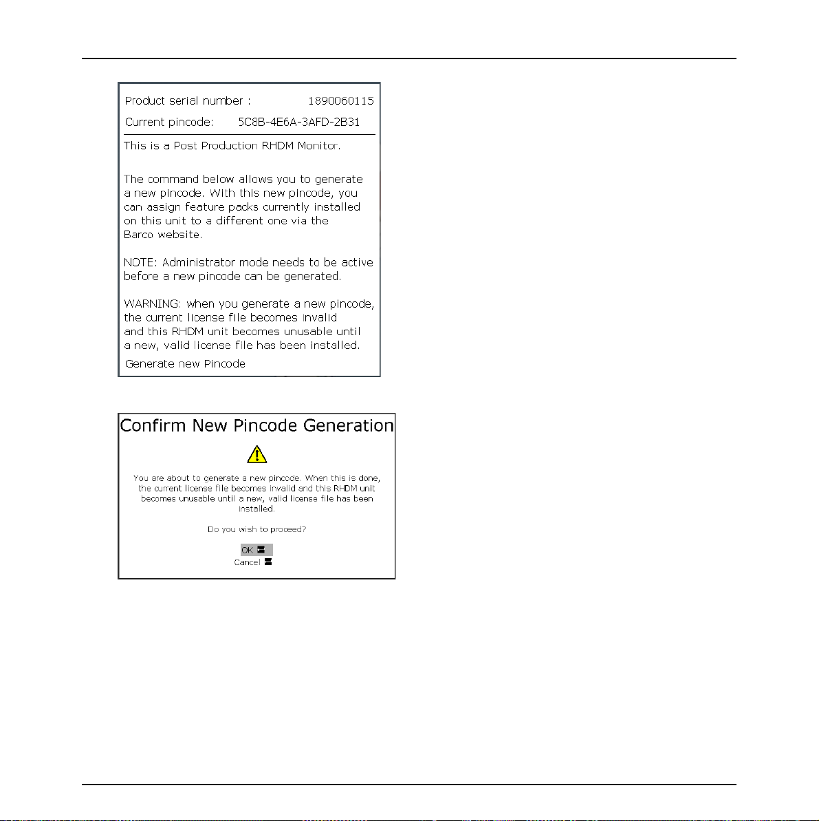
First operation
License OSD menu
Confirming this dialog will remove all feature packs from the display unit and generate a new
pincode.
30 Barco - RHDM-1701 - User manual
Page 31

First operation
• The following message is shown on the screen if “generate new pincode” is confirmed:
It is recommended to deactivate the admin mode after removing the feature packs from the display
unit.
• With the newly generated pincode, you can assign new/other licenses to the product on the
Barco website (https://my.barco.com/productregistration ).
• Generate a new license file. Place the license file on a USB stick and connect the USB stick to all
display units that need to be updated with the new licenses.
• The following message appears when the update is successful and the display unit will function
immediately:
Barco - RHDM-1701 - User manual 31
Page 32

First operation
2.5 Concepts of operation
In this introductory section the concepts of the operation of the display unit will be explained.
Details about the operation of the display unit can be found in the chapter “Full functionality
description”.
Control panel
The operation of the display unit is facilitated by the control panel. The control panel contains
different sections of buttons and knobs that allow the user to interact with the display unit in a fast
and easy way.
Buttons
Some of the buttons (especially the functions keys) have a double functionality and can be used as
follows:
The function keys contain most of the settings of the display unit. It is important to understand the
division of the function keys based on the effect that they have on the processing of the video
signal.
Figure 5: Function keys divided into categories
Short press Instantaneous effect
Long press (press longer
than 2 seconds)
1
2
4
Open a toolbox with advanced settings
3
32 Barco - RHDM-1701 - User manual
Page 33

First operation
Categories of
function keys
1Select input
2View mode
3 Display settings
4 Input settings
Rotary knobs
1
2
Description
The video signals to be viewed on the screen are selected by the user
via a window. There are 2 windows that can be selected by pressing
(
)
lected, pressing (
that are available for that window.
Enables the user to select the way the windows should be viewed on
the screen (e.g. only window 1, only window 2 or both windows
shown next to each other).
These settings have an effect on the full display and affect the video
signal viewed and processed in both windows.
These settings have an effect on each window separately. The settings applied to a window are stored in the memory. Selecting another window to be viewed will not result in loss of the previously defined
input settings of the other window.
3
for window 1 and for window 2. Once a window is se-
) the same button will toggle between the inputs
4
Figure 6: Location of the image adjustment rotary knobs on the control panel
The image adjustment knobs control the settings of Background (1), Picture (2), Saturation (3) and
Hue (4). Changing these settings will result in the display unit working out of the calibrated range.
Background (1), Saturation (3) and Hue (4) apply to the each window separately.
Barco - RHDM-1701 - User manual 33
Page 34

First operation
Figure 7: Picture adjustment bar
When one of the rotary knobs is pressed or turned, the picture adjustment bar is shown at the
bottom of the screen. This information bar shows the actual value of all the rotary knobs.
Trackball
The trackball enables the user to navigate through the menus, change the value of a selected item
and to move the pointer (only in pan&zoom mode).
The
button enables the user to edit and confirm a value or setting in the toolbox or OSD menu.
The
mode.
Status bar
The status bar is shown at the top of the screen and contains relevant information related to the
settings of the input signal settings and the setting of the display unit. The line highlighted in white
indicates the active window.
button also acts as a “left” mouse button for drag and zoom operations in the pan&zoom
Calibrated settings
The display unit is a calibrated instrument that continuously monitors several parameters to ensure
correct representation of colors and luminance levels.
The user can decide to run the display unit in a non-calibrated mode by adjusting the settings
defined by the image adjustment knobs (picture, background, saturation and hue). When the
values of the image adjustment knobs deviate from the calibrated values, the orange light above
the knob will light up. Press (
picture adjustment bar is visible).
The user can also decide to show only one of the 3 color channels or to convert the video signal to
monochrome.
In all these cases also the
the calibrated status of the display unit.
34 Barco - RHDM-1701 - User manual
) the knob to return to the calibrated (default) setting (when the
button will light up orange. Press () the button to go back to
Page 35

2.6 How to setup the display unit
In this section a number of settings are discussed which are primarily preference settings that can
be set by the user.
• Set the Picture (!) to the required luminance. The default value is 100 cd/m
remains calibrated in the allowed picture range (45-150 cd/m2). The picture of the display unit
can thus be adjusted according to the preference of the customer.
• The display unit is a digital display, so the signal black level is always mapped correctly to the
LCD black. Depending on the ambient light illumination and reflection from the screen it might be
necessary to align (lift) the black level using a “Pluge” test pattern and adjusting the Back-
ground ( ) of the display unit.
• Toggle the
The color working space determines the color primaries (comparable to the CRT phosphors) that
are used to display the image on the screen. This setting is a geographic region preference set-
ting.
• Enter the color working space toolbox by pressing
point (default D65). Store the setting under a “Custom” preset.
button until the required color working space is selected (e.g. SMPTE RP145).
( - long press). Set the required white
2
First operation
. The display
• Enter the input window menu by pressing
range to be visualized on the screen (default 64-1019). Select the OETF (opto-electric transfer
function – ‘gamma’) (default is ITU.709).
• Input signals which have an identifier packet describing the type of input signal are processed
automatically by the display unit. When the input signal does not have an identifier packet,
it may be that the display unit is not able to display the input signal correctly. In this case it is
necessary to set the input signal properties manually:
Press to enter the OSD menu.
Use the trackball to move the submenu “Input settings”.
Select the type of input that is connected to the input board (Single or Dual link).
When the signal description in this submenu is not correct, override the signal detection and
set the input signal properties manually. E.g. for Dual Link: RGB, 4:4:4, 10 bit and Segmented frame.
or ( - long press). Set the signal input
Barco - RHDM-1701 - User manual 35
Page 36

How to
3 How to
3.1 Legend
Short press Instantaneous effect
Long press (press longer
than 2 seconds)
Open a toolbox with advanced settings
3.2 How to change the license installed on the display unit
Activate the “Admin mode” that you can find in the main menu
• Press () to open the OSD menu
• Provide the administrator password:
36 Barco - RHDM-1701 - User manual
Page 37

Administrator password is “313329”
• Activate the “Generate new Pincode” in the license OSD menu:
How to
IMPORTANT
:
Do not generate a new pincode unless you plan to install new licenses on your product. Generating a new pincode
will disable the license and the feature packs on your product! When you have generated a new pincode by accident, follow the instructions below to reinstall the license and the feature packs on the display unit.
Figure 8: License OSD menu
Barco - RHDM-1701 - User manual 37
Page 38

How to
Confirming this dialog will remove the license and all feature packs from the display unit and
generate a new pincode.
The following message is shown on the screen if “generate new pincode” is confirmed:
It is recommended to deactivate the admin mode after removing the feature packs from the display
unit.
With the newly generated pincode, you can assign new/other licenses to the product on the Barco
website (https://my.barco.com
38 Barco - RHDM-1701 - User manual
).
Page 39

How to
• Generate a new license file on my.barco.com.
• Place the license file on a USB stick and connect the USB stick to all display units that need to be
updated with the new licenses.
• The following message appears when the update is successful and the display unit will operate
normally immediately:
Barco - RHDM-1701 - User manual 39
Page 40

How to
3.3 How to view signals connected to the SDI input board
INPUT 1 INPUT 2
1
T
O
L
S
A1
B1
IN OUT
IN OUT
Figure 9: Input connectors SDI input board
The standard input board that is mounted in slot 1 is a SDI input board. The SDI input board has
two inputs that are separately connected with a loop-through output connector.
NOTE
:
The input signals are not available at the loop-through output connectors when the display unit is in hard standby
Up to 2 inputs can be applied to the SDI board simultaneously. In the table below the possible
combinations are shown:
Input SDI board Input 1 Input 2
SDI
HDSDI
3Gb/s (optional)
Possible inputs
SDI
HDSDI
3Gb/s (optional)
Dual link (optional)
To select a valid signal, open the input selection toolbox by pressing long (
the window in which the input signal has to be shown
or .
) on the button of
The concept of selection and viewing of the valid signals is summarized in the figure below:
40 Barco - RHDM-1701 - User manual
Page 41

How to
ACTIVE WINDOW
is shown on screen
WINDOW 1
press
press
WINDOW 2
Figure 10: Selection of inputs window 1 & 2
To toggle between the input options for the active window, press (
between the input options. The selected input is shown instantaneously. To change the active
window, press (
instantaneously.
In the example shown in the figure above, window 1 is active and shows the signal applied to input
1 on the screen. Pressing (
Pressing (
this would be input 2) is shown on the screen.
)
) the button of the other window. The other window will be activated
)
will select window 2. When window 2 is active, its selected input (in this example
will toggle between the available inputs (input 1 and input 2).
press
INPUT 1
INPUT 2
INPUT 1
INPUT 2
) the same button to toggle
press
NOTE
:
When no valid input is present for a certain input option, the screen will blank and show the “Invalid input“ icon.
When the display unit was powered off, this is the standard setting for both windows.
Barco - RHDM-1701 - User manual 41
Page 42

How to
IMPORTANT
It is possible to select the same input signal for both windows.
The active window is highlighted in white in the status bar at the top of the screen. When the status
bar is hidden, move the track ball or press a button to show/reveal the status bar. The status bar
hides automatically after the timeout time set in the “OSD settings” menu in the OSD menu.
Figure 11: Zoom in of the status bar at the top of the screen
NOTE
Input settings are connected to the window. When input settings are changed for a specific window , they are stored
instantaneously.
:
:
3.4 How to change the color working space
Figure 12: Location of buttons to change color working space
• Press (
space is shown at the top of the screen in the status bar.
42 Barco - RHDM-1701 - User manual
)
to cycle through the available color working spaces. The current color working
Page 43

OR
How to
• Press (
• Navigate with the trackball to the top of the toolbox “color space”.
• Press (
• Use the trackball to cycle through the defined color working spaces.
• Press (
NOTE
The newly selected color working space is applied instantaneously to the output on the screen and always applies
to both windows. The color working space which is currently used to display the image on the screen, is shown in
the status bar.
)
)
)
:
to open the color working space toolbox.
or () to change the color working space.
or () to confirm the color working space.
3.5 How to visualize the dark levels
The dark levels are accessible with the background control on the image adjustments knobs.
The background control can be changed between -127 and 128 and is set to 0 by default. The unit
of the values of the background control is expressed as a number of levels (in 8-bit steps).
Figure 13: Location of the background adjustment control
By increasing the value of the background, the information in the footroom of the video signal
(below 0% video signal) becomes visible.
Barco - RHDM-1701 - User manual 43
Page 44

How to
100 %
e
v
i
r
d
D
C
L
clipping
bright levels
+
Visualize
super bright
-
Black
offset
Visualize
super dark
Black
0 %
clipping
dark levels
White
100 %
Video signal
44 Barco - RHDM-1701 - User manual
Page 45

3.6 How to maximize contrast
To maximize the contrast of the display unit, the following settings can be applied:
Black correction
• When the correctness of the colors at the dark grey levels is of lower importance than the contrast, the contrast can be enhanced by setting the black correction to 0%.
How to
• Go to the OSD menu by pressing (
• Move with the trackball to select the “Input settings” in the main menu.
• Press (
menu
• Move with the trackball down to the “Black correction” setting of the appropriate window
• When black correction is set at a value different from 0%,
)
press (
or () , or move with the trackball to the right to open the “Input settings”
)
or () to select the value
)
move with the trackball down or type “0” on the numeric keypad to set the value to 0%
press (
• Move with the trackball down to the “Uniformity” and uncheck the box by pressing (
)
(
)
.
or () to confirm the value
)
Barco - RHDM-1701 - User manual 45
or
Page 46

How to
Set the signal range of the input signal
If there are no colors in the headroom and/or the footroom, the contrast can be enhanced by
clipping the headroom and/or the footroom. When clipping occurs, a certain portion of the input
range of the video signal is mapped to the maximum light output of the LCD.
• Press (
dow 1 and
• Move with the trackball to select the “signal range” setting
• Press (
• Move with the trackball up/down to set the new signal range
• Press (
)
)
)
/
to open the “select input” toolbox ( if the input signal is shown on win-
if the input signal is shown on window 2)
or () to select the signal range 64-940.
or () to confirm the selection
3.7 How to correct the black level
In some cases the correctness of the colors at the dark grey levels are of higher importance than
the contrast. The black correction in the “Input settings” OSD menu can be set for each window
separately.
To optimize the color correctness of the dark grey levels, the black correction should be set to
100%. As a tradeoff for the optimized color correctness of the dark grey levels, the contrast is
reduced.
When the black correction is set to 0%, the contrast is maximized.
• Go to the OSD menu by pressing (
• Move with the trackball to select the “Input settings” in the main menu.
• Press (
• Move with the trackball down to the “Black correction” setting of the appropriate window
• When black correction is set at a value different from 100%,
)
press (
or () to open the “Input settings” menu
)
or () to select the value
move with the trackball up or type “100” on the numeric keypad to set the value to 100%
press (
)
or () to confirm the value
)
46 Barco - RHDM-1701 - User manual
Page 47

3.8 How to enable native interlaced mode (black line insertion)
Set the Deinterlace mode to “black line insertion”:
How to
• Go to the OSD menu by pressing (
• Move with the trackball to highlight the “Input settings” in the main menu
• Press (
• Move with the trackball to the “Deinterlace mode” setting of the appropriate window
• Press (
• Move with the trackball (up or down) to select “black line insertion” mode
• Press (
)
)
)
or () to open the “Input settings menu”
or () to select the mode
or () to confirm the “black line insertion” mode
)
3.9 How to change the aspect ratio
Track ball
Figure 14: Location of the button to change the aspect ratio
• Press (
neously to the window.
or
• Press (
• Select the aspect ratio using the trackball.
• Press (
)
)
)
to toggle between all possible aspect ratios. The aspect ratio is applied instanta-
to open the aspect ratio mode selection toolbox.
or () to confirm the selection.
Barco - RHDM-1701 - User manual 47
Page 48

How to
NOTE
:
The aspect ratio can be set for each window separately.
3.10 How to select a color channel
Track ball
Figure 15: Location of buttons to select a color channel
1. Set the color channel
• Press ()
• Select “Channel selection”
Move with the trackball to highlight “Channel selection”
Press (
immediately to the selected window.
• Select the color channel
)
or () to activate the “Channel selection” option. The setting is applied
Move with the trackball to highlight a color channel
Press (
the selected window.
48 Barco - RHDM-1701 - User manual
)
or () to select a color channel. The setting is applied immediately to
Page 49

How to
• When “Show in monochrome” is selected, the selected color channel will be shown in monochrome.
• Press (
2. Toggle between full color and the selected setting
• Press () . The setting is applied immediately to the selected window.
NOTE
•
The color channel selection toolbox shows the selected color channel for the active window only.
•
When only one color channel is selected, the cal/err indica tor light wi ll light-u p orange to alert the user the display
unit is working out of the calibrated range.
)
:
to exit the color adjustments toolbox.
3.11 How to show two input signals next to each other
• Press ()
SINGLE INPUT
WINDOW 1 WINDOW 2
PAN&ZOOM
WINDOW 1
DUAL VIEW
WINDOW 2
Figure 16: View mode functionality
Barco - RHDM-1701 - User manual 49
Page 50

How to
pointer
double arrow
The inputs selected for window 1 and window 2 are shown together on the screen. When the
display is showing the inputs in Pan&Zoom or dual view mode, the input settings can still be
changed by pressing
available inputs for that window. The changes will be shown instantaneously.
In the
mode it is possible to pan the image and to zoom in on the image. These functions can be
performed for window 1 and window 2 separately.
To change the relative size of the two parts of the screen in the Pan&Zoom mode:
In the
remains unchanged while up- or downscaling.
Pan&Zoom mode
• Move with the pointer to the separating line in the middle of the screen using the trackball
• When the double arrow appears while hovering with the pointer above the separating line, press
(continuously) and drag the separating line to the left or the right using the trackball
• Release
dual view mode
to leave the separating line at the obtained position
or
to activate the respective window and/or cycle through the
the two inputs are shown in full format (cropped) on the screen. In this
, the two inputs are scaled to fit the new window size. The aspect ratio
50 Barco - RHDM-1701 - User manual
Page 51

3.12 How to pan the image
Track ball
Figure 17: Location of buttons to pan the image
Pointer – can be used for panning
How to
• Press (
to each other.
• Move the “pointer” (using the trackball) to the window where the video signal has to be panned.
• Press
released, the “pointer” can be moved to pan the other window or to perform a new pan on the
same window.
)
until the Pan&Zoom setting is selected. Window 1 and window 2 are shown next
(continuously) to grab the image and use the track ball to pan the image. When is
Barco - RHDM-1701 - User manual 51
Page 52

How to
3.13 How to zoom in on the image
Track ball
Figure 18: Location of buttons to zoom in on an image
pointer
magnifying glass
• Press (
to each other.
• Pan the image to the appropriate position on the screen.
• Press
• Move the magnifying glass (using the trackball) to the location where the video signal has to be
zoomed in.
• Press
released, the magnifying glass can be moved to another window or another spot on the screen.
IMPORTANT
When an image is zoomed, pixel repetition is used to display the image on the screen. This means that the image
is magnified according to an integer amount. No scaling artifacts are introduced.
52 Barco - RHDM-1701 - User manual
)
until the Pan&Zoom setting is selected. Window 1 and window 2 are shown next
to select the magnifying glass.
continuously to lock the place and use the trackball to zoom in/out. When is
:
Page 53

3.14 How to work with presets
3.14.1 Use case
User settings can be stored in a so-called preset. There are up to 6 possible presets. The first one is
the factory preset and contains the default user settings, the next five can be used by the user to
store settings.
New settings can be loaded from one of the defined presets, which involves overwriting the current
user settings with the values defined in the preset.
Presets can be transfered from one RHDM monitor to another via USB.
3.14.2 Restoring the active preset
A short press on the calibration button loads/restores the current active preset.
Use case example:
Suppose preset 1 was loaded and is thus the current active preset.
A user changes on purpose or by accident some of the critical user settings. As a result the CAL
button will light up orange to indicate this. As explained in the LED’s subparagraph of the Control
panel paragraph.
A short press on the button
that all critical user settings are as defined in the preset again.
Basically it allows you to return to current active / last loaded preset.
will reload preset 1, the button will light up white to indicate
How to
Barco - RHDM-1701 - User manual 53
Page 54

How to
3.14.3 Loading/Storing & Erasing presets
Via OSD “Presets”
• Go to the OSD menu by pressing ()
• Move with the trackball to select the “Presets” in the main menu.
• Press (
• Move with the trackball to “Load”, “Store” or “Erase”, depending on the desired action and press
(
54 Barco - RHDM-1701 - User manual
)
)
or () , or move with the trackball to the right to open the “Presets” menu
or () to open the submenu.
Page 55

• Move with the trackball to the desired preset
Press (
Press (
stored can be changed (optionally) and the preset can be stored.
Via web interface page “Preset management”
• Select “Preset management” from the selection menu on the left hand side of the webpage.
• Go to “Preset to load” to load either the factory preset or one of the 5 user presets.
• Go to “Store Current Settings as” to store the current settings to one of the 5 user presets.
• Go to “Preset to remove” to remove a selected preset.
)
)
to “Load” or “Erase” the selected preset.
to “Store” to open the Store submenu where the name of the preset to be
How to
Barco - RHDM-1701 - User manual 55
Page 56

How to
56 Barco - RHDM-1701 - User manual
Page 57

3.14.4 Preset names and filenames
The preset names as shown in the Load and Store submenu's of the OSD rep resent the names of
the preset files.
Following filename syntax is used:
<preset number>-<name>.pre
<preset number>:
<name>:
the name in the Store submenu.
Example:
So preset 1 with name 'Test 1' will be represented by a file with name '1-Test 1.pre'.
The name of the preset as shown in the Load/Store submenu or when defining
The preset number, 1 for preset 1, 2 for preset 2, ...
3.14.5 Transferring presets over USB
How to
Via OSD
User presets created on one RHDM monitor can be transferred to another monitor by using an USB
stick.
Upon plugging in an USB stick a popup menu will appear on the OSD with the option to copy
Presets from USB stick to display or vice-versa:
Barco - RHDM-1701 - User manual 57
Page 58

How to
NOTE
:
The popup window will not appear if both display and USB stick do not contain any presets.
The presence of an upload package might also prevent the popup window from appearing.
Depending of the availibility of presets on either USB stick or monitor, the popup menu might
provide 2 or 3 options. Those 3 options are:
Install presets from USB drive:
•
This will copy presets from the USB stick to the display. This
option is only available if the USB stick has presets in the root of the USB stick. The presets are
represented as files on the root of the USB stick and must be named '1-....pre' ... '5-.....pre',
representing presets 1 ... 5. If for example the USB stick contains two preset files in its root '1name1.pre' and '4-some_name.pre' then by invoking this option, presets 1 and 4 on the display
will be replaced by those on the USB stick. Note that installing presets from a USB stick also
reloads the current active preset.
•
Copy preset to USB drive:
Copies presets from the display to the USB stick. This option is only
available if the display has presets. The presets will be located in the root of the US B stick and
named 1-....pre ... 5-....pre.
58 Barco - RHDM-1701 - User manual
Page 59

•
Cancel:
Quits the popup menu without any action.
Via web interface page “Preset management”
• Select “Preset management” from the selection menu on the left hand side of the webpage.
• Go to “Download presets” to download presets from the monitor into your PC.
• Go to “Preset to upload” to upload a preset file from your PC to the monitor.
How to
Barco - RHDM-1701 - User manual 59
Page 60

How to
60 Barco - RHDM-1701 - User manual
Page 61

3.15 How to use the 3D-LUT feature
3.15.1 Use case
Post-production professionals must deal with different type of source content that must be
conformed, edited, color-graded and finished before the final deliverable is produced. The different
types of content have different properties in terms of gamma, color gamut, white point, contrast
etc. The used preview display devices also have different properties than the intended deliverable
or target medium.
So a level of color consistency is needed, not only making different types of content look correct on
the preview device, but also making the preview device look like the intended target medium.
This color consistency is achieved by using color/gamut mapping. A practical way of gamut
mapping is to use look-up tables, that transform a given signal value to a new value. The used tool
for gamut mapping is a three-dimensional look-up table (3D-LUT).
Currently the monitor supports three types of user 3D-LUT files: Truelight, Cinespace and
Autodesk.
A user 3D-LUT file can be uploaded to the monitor either via the web interface or via a USB stick.
The activation of the 3D-LUT can be done via the “User 3D LUT” web interface or via OSD menu
“Input settings”.
3.15.2 3D-LUT upload via USB stick
How to
• Prepare data on USB stick
Copy your 3D-LUT file to the root of your USB stick and set its name to 3d.lut. This name is
hardcoded and case-sensitive.
NOTE
:
Make sure that there are no RHDM software or license files in the root of the USB, as they have precedence.
Barco - RHDM-1701 - User manual 61
Page 62

How to
• 3D-LUT upload
Plug in the USB stick in the USB port of the display unit. The file is automatically uploaded
into the unit. Give the monitor 15s time to copy the file before removing the USB stick
To use the new user 3D-LUT file, the file should be activated via the “Input settings” OSD
menu or via the web interface.
3.15.3 3D-LUT upload via web interface
• Connect the display unit to the local network
Plug an ethernet cable in ethernet port 0 or ethernet port 1.
• Connect with the pc to the display unit
Check the IP address that is assigned to the ethernet port. Press () to open the “Dis-
play Information” toolbox. Write down the IP address of the corresponding ethernet port.
Open a browser window and type in the Address bar: “http://” + the IP address + “/” (e.g.
“http://150.158.200.140”). The web interface of the display unit will open.
62 Barco - RHDM-1701 - User manual
Page 63

• 3D-LUT file upload
Select “User 3D LUT” from the selection menu on the left hand side of the webpage.
Click on Upload file... to go to the “Upload Custom 3D LUT” page.
Browse for a User 3D-LUT file by clicking on the Browse... button. Note that the file can
have any name and doesn't have to be name 3d.lut.
How to
Hit the upload button to upload the file to the monitor.
Barco - RHDM-1701 - User manual 63
Page 64

How to
3.15.4 3D-LUT activation
Via OSD “Input settings menu”
• Go to the OSD menu by pressing (
• Move with the trackball to select the “Input settings” in the main menu.
• Press (
menu
• Move with the trackball down to “User 3D LUT” and press (
menu.
• Check the box “Enable” by pressing (
loaded in the display unit.
Via web interface page “User 3D LUT”
• Select “User 3D LUT” from the selection menu on the left hand side of the webpage.
• Check “LUT active on window 1” to activate the 3D-LUT file on window 1
• Check “LUT active on window 2” to activate the 3D-LUT file on window 2
64 Barco - RHDM-1701 - User manual
)
or () , or move with the trackball to the right to open the “Input settings”
)
)
or ()
)
to activate the 3D-LUT file that was
or () to open the sub-
Page 65

3.16 How to upload new software
3.16.1 Important notice
Major and minor software updates exist for the display unit. A major software update is marked by
a change in the first order digits (e.g. from 1.xx to 2.xx) while a minor software update is marked
by a change in the second order digits (e.g. from 1.00 to 1.01).
How to
IMPORTANT
It is not possible to
:
downgrade
the software version of the display unit with a major software revision.
3.16.2 Software upload via ethernet
1. Connect the display unit to the local network
• Plug an ethernet cable in ethernet port 0 or ethernet port 1.
2. Connect with the pc to the display unit
• Check the IP address that is assigned to the ethernet port. Press () to open the “Display
Information” toolbox. Write down the IP address of the corresponding ethernet port.
Barco - RHDM-1701 - User manual 65
Page 66

How to
• Open a browser window and type in the Address bar: “http://” + the IP address + “/” (e.g.
“http://150.158.200.140”). The web interface of the display unit will open.
66 Barco - RHDM-1701 - User manual
Page 67

How to
3. The software upload
• Select “Admin…” from the selection menu on the left hand side of the webpage.
Barco - RHDM-1701 - User manual 67
Page 68

How to
• An authentification will be requested. To enter the Admin section:
User name: “admin”
Password: “admin117234”
• When the valid user name and password are entered, the Admin section will be opened in the
webpage.
• Click on “Upgrade firmware”
68 Barco - RHDM-1701 - User manual
Page 69

How to
• Click on “Browse” and select the debian software upload package (xxx.deb) that needs to be
uploaded into the display unit.
• Start the upload of the software by pressing “Update”. The upload of new software will start
immediately. The pc will show the progress of the software upload while the display unit will
show the following warning message on the screen:
• After the software upload, the display unit will reboot automatically and will start-up using the
newly uploaded software.
IMPORTANT
:
If the upload of the new software would fail or woul d be interrupted, the display unit will reboot into the failsafe
mode. The software version of the failsafe mode is the most recent software version that was uploaded successfully.
Barco - RHDM-1701 - User manual 69
Page 70

How to
3.16.3 Software upload via USB
1. Prepare data on USB stick
• Save the new software upload package (xxx.deb) on a USB stick. Place the file in the root and
not in a folder.
IMPORTANT
Make sure that the filename starts with ‘rhdm’ written in lower cases.
2. Software upload
• Place the USB stick in a USB port of the display unit at the back of the display unit.
• The display unit will search for the latest software upload file. The following warning window
appears on the screen
• The display unit will automatically start the software upload after
unit is powered off or the USB stick is removed. When the display unit is busy with the upload of
the new software, the following warning is shown on the screen:
:
10 seconds
unless the display
• When software update has started (“Software update busy”) the USB stick can be removed (all
data is already transferred).
70 Barco - RHDM-1701 - User manual
Page 71

• The display unit automatically reboots after finishing the software upload.
How to
IMPORTANT
If the upload of the new software would fail or woul d be interrupted, the display unit will reboot into the failsafe
mode. The software version of the failsafe mode is the most recent software version that was uploaded successfully.
NOTE
It is advisable to remove the USB stick after software update since the display unit will automatically recognize the
firmware on the USB stick at each power up or activation from hard standby. The display unit will then start the
automated firmware update process. This does not happen after the reboot resulting from the software update!
:
:
Barco - RHDM-1701 - User manual 71
Page 72

Full functionality description
4 Full functionality description
4.1 Operation
4.1.1 Overview of operation functionalities
1
2
3
4
5
6
Figure 19: Overview of operational controls, indicators and OSD functionalities
Different operation interfaces:
1) Status bar
2) OSD menu
3) Toolbox
4) Under Monitor Display bar / Picture Adjustment bar
5) Control panel
6) Indicator lights
4.1.2 Operational mode overview
The operational status of the display unit can be summarized in the figure below:
72 Barco - RHDM-1701 - User manual
Page 73

Full functionality description
Figure 20: Operational mode overview
Barco - RHDM-1701 - User manual 73
Page 74

Full functionality description
4.1.3 Indicator lights
2
1
3
1 Standby/Power LED (green or orange)
2Fault LED (red)
3 Calibration LED (orange)
Figure 21: Location of indicator lights
The indicator lights give information about the status of the display unit.
Standby/Power LED:
• Orange: The display unit is in soft standby. All signals at the input boards are processed. The
backlights and panel are turned off.
• Green: The display unit is powered. All signals at the input boards are processed.
• LED is not lit: The display is in hard standby or the power connector is disconnected.
Fault LED:
• Red: A Fault has occurred.
74 Barco - RHDM-1701 - User manual
Page 75

Full functionality description
IMPORTANT
When an error occurs, consult in the OSD menu the OSD submenu “Faults and warnings” to read the warning and/
or fault messages.
Calibration LED:
• Orange: The display unit is operating out of the calibrated range.
:
4.1.4 Control panel
4.1.4.1 Overview operation control panel
Figure 22: Drawing of the control panel
The control panel allows the user to change a wide variety of settings in a clear and easy way. To
apply the desired settings, the control panel is equipped with:
• a USB port
• press buttons
• press and rotary knobs
• a trackball
4.1.4.2 USB port
A USB storage device with the latest firmware will immediately be recognized and the display unit
will initiate a firmware upload automatically . It is also possible to connect a mouse as a replacement
of the trackball and the
(left button) and (right button) buttons.
Barco - RHDM-1701 - User manual 75
Page 76

Full functionality description
4.1.4.3 Press buttons
The press buttons have a “short press” and a “long press” functionality. In this manual the action of
a short or long press is indicated by the following icons:
When the buttons are pressed shortly, the function is immediately applied to the image.
Most of the buttons have an advanced function when the button is pressed for a long time (longer
than 2 seconds). In the latter case, a
Some buttons on the numeric keypad can be used a s a
Short press Instantaneous effect
Long press (press longer
than 2 seconds)
Open a toolbox with advanced settings
toolbox
appears on the left hand side of the screen.
function key
.
4.1.4.4 Press and rotary knobs
The rotary knobs are used for easy adjustments of basic settings.
Turning the rotary knob:
• Image adjustment bar not visible: image adjustment bar is shown
• Image adjustment bar visible: value that corresponds to the rotary knob is changed
Turning clockwise = increasing value
Turning counterclockwise = decreasing value
Pressing the rotary knob:
• Image adjustment bar not visible: image adjustment bar is shown
• Image adjustment bar visible: value that corresponds to the rotary knob is set to its default and
calibrated value.
4.1.4.5 Trackball
The trackball allows the operator to move the pointer or navigate in the menus.
4.1.4.6 LEDs
Power on and input calibrated:
• The power button is lit green.
• All other buttons are lit white.
76 Barco - RHDM-1701 - User manual
Page 77

Full functionality description
Standby:
• The power button is lit orange.
• All other buttons are lit white.
Power on and input not calibrated:
• The power button is lit green.
• The calibration button is lit orange.
• The LED above the image adjustment knob is lit orange when the setting is out of the calibrated
range for the selected input. When the calibration is performed, by pressing the calibration button, the orange lights disappear and the calibration button is lit green.
• All other buttons are lit white.
Calibration button illumination (presets):
• Calibration button is lit orange: indication that a critical user setting differs from the last loaded
preset.
• Calibration button is lit white: indication that all critical user settings are as defined in the active
preset, when loading a preset.
The user settings that are judged critical are:
Background, Picture, Saturation, Hue, Gain, OETF setting, Gamma setting, Gamma
signal range, Gamma headroom level, Gamma footroom level, Monochrome setting,
Any setting related to the R-G-B button (Color Channel Selection), Color work space
selection, Deinterlace mode, Black correction, User 3D lut enable
IMPORTANT
:
To see which setting causes the CAL button to light up amber check the OSD submenu “Faults and warnings”.
Barco - RHDM-1701 - User manual 77
Page 78

Full functionality description
NOTE
:
The lights behind the buttons go out 10 seconds after all activity on the control panel has stopped. The buttons
remain active when the lights after the buttons are out. Pressing a darkened button will execute the function
represented by the button immediately. Only the power button is functional when the display unit is in hard
standby.
4.1.5 Status bar
The status bar is shown at the top of the screen and contains information related to the selected
signals for window 1 and window 2.
Figure 23: Screenshot status bar (upper part – left side, lower part – right side)
The following information is shown:
• Window for which the information is valid
• Input board that is used to process the selected input signal
• Input detection overrule indicator
• Input signal description
• OETF
• Color subsampling
• Encoding
• Scale mode
• Aspect ratio
• Backlight scan mode
• Light output
• Color working space
• Latency of the input signal selected by the active window (0 ms when no signal is connected)
78 Barco - RHDM-1701 - User manual
Page 79

Full functionality description
The information of the active window (displayed on the screen) is highlighted in white.
NOTE
:
In dual view or pan&zoom mode, both input signals selected by the windows are shown on the screen. The active
window is still highlighted in white in the status bar and refers to the fact that certain settings can be changed for
the active window only (e.g. toggle between color and monochrome by pressing (
active window).
)
will only be applied to the
4.1.6 Invalid signal indicator
Figure 24: “Invalid signal” indicator
When the signal selected by the active window is not valid, or when there are no signals available,
then the “Invalid signal” indicator is shown on a black screen.
4.1.7 Under monitor display bar (optional)
Figure 25: Screenshot UMD bar with two tally lights
The Under Monitor Display (UMD) bar is shown at the bottom of the screen and has two tally lights.
4.1.8 Picture adjustment bar
Barco - RHDM-1701 - User manual 79
Page 80

Full functionality description
Figure 26: Screenshot Picture adjustment bar
The picture adjustment bar appears at the bottom of the screen (over the UMD) when the setting of
Background, Picture, Saturation or Hue is changed.
4.1.9 Pointer functionality
Icon Description Action
Pointer pan the image
Pointer out of active zone none
Magnifying glass zoom in/out
double arrow Resize windows
The pointer is activated when the display unit is in the “pan&zoom” mode. When the pointer is in
the active zone (where the video is displayed), the “hand” is shown. When the pointer in out the
active zone (status bar or picture adjustment bar), the “arrow” is shown. The following actions can
be done:
• Pressing (
• Pressing (
)
)
toggles between the pointer and the magnifying glass.
activates the “action” property. Use the trackball to execute the action.
4.1.10 Toolbox
The toolbox of a particular setting appears on the screen when a button is pressed for a long time
). The toolbox appears on the left side of the screen and reveals additional settings. A
(
screenshot of the Color Channel Selection toolbox is shown below as an example:
80 Barco - RHDM-1701 - User manual
Page 81

Full functionality description
The trackball can be used to navigate in the toolbox and to select a setting. Settings can be
activated and deactivated by pressing (
The value of the setting can be changed when “up” and “down” arrows appear right after the value
(see picture above). Press (
) again or to confirm the new value.
) the select button
or by pressing () .
The timeout of the toolbox can be set in the OSD menu. The toolbox can be closed by pressing (
the exit button
on the control panel or by selecting the cross in the top right corner.
4.1.11 On screen display menu
The On Screen Display (OSD) menu contains the settings that are not frequently used. The OSD
menu can be accessed by pressing (
The trackball can be used to navigate in the menu and to select an option and/or setting. Moving
up/down with the track ball will allow scrolling through the different options. Moving the track ball
to the left will close the OSD submenu. Moving the track ball to the right will open a deeper OSD
submenu.
Settings can be activated and deactivated by pressing (
The timeout of the OSD menu can be set in the OSD menu “OSD settings”. The OSD menu can be
closed by pressing (
)
.
)
on the control panel.
)
Barco - RHDM-1701 - User manual 81
or by pressing () .
)
Page 82

Full functionality description
4.1.12 Web interface
The display unit has a web interface. When a pc is connected via the local network or directly to one
of the ethernet ports of the display unit, the settings of the display unit can be monitored and/or
changed via the pc.
The web interface can be loaded via a standard web browser by browsing to the IP address of the
ethernet port of the display unit that is connected to the local network.
4.2 Settings control panel and toolbox
4.2.1 Overview buttons control panel
The display unit can be operated with the control panel. The control panel is divided in different
functional blocks. The functionality of the buttons in each block will be discussed in detail in the
following sections.
3
2
1
Figure 27: Control panel
The buttons on the control panel can perform an instantaneous operation or open a toolbox,
depending on whether the button is pressed short (
82 Barco - RHDM-1701 - User manual
Short press Instantaneous effect
Long press (press longer
than 2 seconds)
4
Open a toolbox with advanced settings
5
) or long ().
6
7
Page 83

The control panel consists of the following functions:
Block Functionality
Full functionality description
1USB connector
2 Control buttons
3Fault LED
4Image adjustment
knobs
5 Function keys
6 Numeric keypad
7 Navigation pad
Access to the display unit to upload new display firmware in an
automated way.
Allows the operator to switch the display unit on/off and set the
display unit to preset and calibrated values.
Lights up when a “fault” is detected by the display unit.
Adjusts the Background, Picture, Hue and Saturation of the displayed video signal.
Groups all basic functions that can be used to display the input
signal.
Keypad to enter numeric values.
Buttons to access the On Screen Display (OSD), to select items
and to call possible options. A trackball for easy pointer movement.
4.2.2 Control buttons
4.2.2.1 Overview control buttons
Figure 28: Control buttons
Barco - RHDM-1701 - User manual 83
Page 84

Full functionality description
4.2.2.2 Power button
Function Description
Power button
Display unit is switched off:
•
switches display unit on
Display unit is switched on:
•
sets the display unit into soft standby mode. The panel and
backlight are disabled.
•
sets the display unit into hard standby mode. The panel,
backlight and electronics are disabled. Only the
mains functional.
button re-
84 Barco - RHDM-1701 - User manual
Page 85

4.2.2.3 Screen select button
Function Description
Screen select
Full functionality description
Opens the Display information toolbox:
Display name:
•
•
Serial number:
Software version:
•
software
Network information:
•
eth0/ eth1
DHCP: switches the DHCP protocol on/off
IP Address: current IP address assigned to the display
unit
IP Netmask: current netmask address
Gateway: current gateway address
MAC: MAC address of the ethernet port
Apply:
•
Cancel:
•
Refresh:
•
and MAC address.
Note:
changed using the trackball. Press (
edit the value with the trackball. The value can also be
edited by typing the numbers using the numeric keypad
on the control panel (use
puts). When the desired value is reached, Press (
or
confirm the changes of the settings
cancel the changes of the settings
To change a value, select the item that has to be
to confirm.
Name of the display unit
Serial number of the display unit
Version of the currently active
refresh the IP address, IP netmask, Gateway
)
to cancel erroneous in-
or and
)
4.2.2.4 Calibration button
Function Description
Calibration
Resets Background, Picture, Hue and Saturation and RGB/
Mono select to the preset values. The
the
space toolbox
button. The last selected/saved preset in the color working
will be selected by pressing () .
button is connected with
Barco - RHDM-1701 - User manual 85
Page 86

Full functionality description
4.2.3 Fault LED
Figure 29: Fault LED
The Fault LED lights up when a hardware failure is detected by the display unit. The Fault LED does
not refer to the display unit operating in non-calibrated mode. When the Fault LED lights up red, the
Cal/Err indicator LED on the bezel will also light up red.
IMPORTANT
When an error occurs, consult the OSD submenu “Status controller” to check the warning and/or fault messages.
NOTE
When the display unit starts-up from a hard standby status, the Fault LED lights up during the initialization. When
the control panel is fully operational and when the display unit did not detect problems during start-up, the Fault
LED will go out.
:
:
86 Barco - RHDM-1701 - User manual
Page 87

4.2.4 Image adjustment knobs
Figure 30: Image adjustment knobs
Function Description
Full functionality description
!
#
$
Pressing the knob (
NOTE
•
of the calibrated range. The LED above the knob will light up orange.
•
knob acts on the entire screen.
Background Adjusts the background (from -127 to +128). The background is equiv-
alent to video offset and is expressed in 8-bit steps.
Calibrated value: 0 (default)
Picture Adjusts the picture (from 45 to 200). The picture is expressed in cd/m2
Saturation Adjusts the saturation (from 0 to 250). The saturation is expressed in
Hue Adjusts the hue (from -90 to +90). The hue is expressed in degrees (°).
(nit).
Calibrated value: 100 (default)
The calibration of the color gamut, white point and gamma is main-
tained when the picture is between 45 cd/m
percentage (%).
Calibrated value: 100 (default)
Calibrated value: 0 (default)
2
and 150 cd/m2.
) sets the value back to the calibrated (preset) value.
:
When the value of the image adjustment knobs deviates from the calibrated value, the display unit operates out
The image adjustments knobs Background, Saturation and Hue act only on the active window.
The Picture
Barco - RHDM-1701 - User manual 87
Page 88

Full functionality description
4.2.5 Function keys
4.2.5.1 Overview function buttons
Figure 31: Function buttons
Input range settings
The figure above illustrates the influence of the selected input range on the conversion of
the input signal to the image which is shown on the screen. For SDI signals the range can
be set to 4-1019 (maximal). For DVI signals the input range can be extended to 0-1023
(maximal).
88 Barco - RHDM-1701 - User manual
Page 89

4.2.5.2 Select input button
Function Description
Full functionality description
Select input
Toggle between input selections for Window 1 (2).
Each input is instantly displayed on the screen. When
window 1 (2) is valid/active, pressing
tivate the other window 2 (1).
Input configuration toolbox appears. The available
inputs for window 1 (2) are listed. Move with the trackball to select an input and press
lected input.
For all available input signals, the timing, color sub-sampling and frequency is shown.
If 2 windows are shown next to each other, the left window is window 1.
The input signals applied to the display unit are automatically detected and placed in the input selection list (
tomatic input detection
Gamma Settings:
window only.
OETF:
•
Possible settings are: xvYCC, Rec.709, Pure Gamma, Extended Gamma, SMPTE 240M or sRGB.
•
•
settings are 0-1023, 4-1019, 4-940, 54-1019 or 64-940.
•
Headroom level:
el.
Footroom level:
•
Setting of the opto-electrical transfer function.
Gamma:
Signal range:
Custom setting of the gamma exponent.
these settings apply to the selected
Setting of the signal range. Possible
custom setting of the footroom level.
).
custom setting of the headroom lev-
(
to confirm the se-
) will ac-
au-
IMPORTANT
The Gamma settings apply to the selected window only. All signals processed by that window ( or ) will be
subjected to the gamma settings defined by the customer.
:
Barco - RHDM-1701 - User manual 89
Page 90

Full functionality description
4.2.5.3 View mode button
Function Description
View mode
Toggle between different modes.
Pan&Zoom
•
to each other (split screen mode). The signals are
cropped (no up scaling or down scaling of the image). It
is possible to pan (select the area of the image that is
viewed) and zoom on the two windows separately. It is
also possible to show the same signal in both windows
(see navigation pad for more info on the pan & zoom
functionality).
On the left side window 1 is shown. The trackball can be
used to move a pointer over the screen. Use
choose between pan and zoom.
Dual view
•
to each other (split screen mode). The images are adjusted to fit the new window borders. The aspect ratio is
maintained during this upscaling or downscaling.
•
Single input
4.2.5.4 Display and backlight scan mode button
Function Description
Display and backlight scan
mode
Toggles between the scan modes (applies to both
windows). The scan mode is shown in the status bar.
Scan mode selection toolbox appears:
The possible selection of scan modes are:
Non-scanning backlight:
•
mode is switched off.
Scanning backlight:
•
activated.
: Window 1 and window 2 are shown next
to
: Window 1 and window 2 are shown next
: The input of the active window is shown.
The scanning backlight
The scanning backlight mode is
90 Barco - RHDM-1701 - User manual
Page 91

NOTE
:
The “black line insertion” mode cannot be combined with the “scanning backlight” mode. When the “scanning
backlight” mode is selected, the “black line insertion” mode will automatically be changed to the “deinterlace” mode
until the “scanning backlight” mode is switched back to the “non-scanning backlight” mode.
4.2.5.5 Color working space button
Function Description
Full functionality description
Color working space
Toggles between different color working spaces.
The color working space applied to the display unit is
shown in the status bar.
Color workspace toolbox appears:
Color space
•
play unit.
Primaries:
•
White point:
•
color working space. Range of white points.
Store:
•
space. When the value of gamma, the primaries or the
white point is changed, an asterisk will appear behind
the name of the selected color working space. By
pressing Store, the values will be saved into a new color
working space. The name of this color space will be
“custom”, followed by an incremental number.
•
Remove:
custom defined color working spaces can be removed.
: Selection of the color space for the dis-
The primaries of the color working space.
Coordinates of the white point of the
The user can define a custom color working
Removes the selected color space. Only
Barco - RHDM-1701 - User manual 91
Page 92

Full functionality description
NOTE
:
To change a value, select the item that has to b e changed using the trackball. Press () or and edit the
value with the trackball. The value can also be edited by typing the numbers using the numeric keypad on the
control panel (use
confirm.
to cancel erroneous inputs). When the desired value is reached, Press () or to
IMPORTANT
The color working space is always selected for both windows simultaneously. After selecting a color working space,
this color working space is maintained, even when other input signals are selected for window 1 and/or window 2.
IMPORTANT
The primaries can only be adjusted with the “Post production” license of the display unit (RHDM/P).
Figure 32: Location of buttons to customize the color working space
:
:
Track ball
Customize color working space:
• Press () to open the color working space toolbox.
• Navigate with the trackball to the top of the toolbox “Select color space”.
• Press (
92 Barco - RHDM-1701 - User manual
)
or () to change the color working space.
Page 93

Full functionality description
• Use the trackball to cycle through the defined color working spaces.
• Press (
• Change the value of an item
)
or () to confirm the color working space to be customized.
Navigate with the trackball to highlight the setting that needs to be customized.
Press (
)
or () to select the highlighted item.
Use the numeric keypad to enter a new value. The values are entered from left to right.
Press (
change the value of the highlighted item.
Press (
NOTE
:
When a color working space has been changed but not yet stored, an asterisk (*) will appear after the name of the
color working space. When the display unit is switched off or placed in hard standby, all changes will be lost.
Store the customized color working space:
• Navigate with the trackball to highlight the item “store”.
• Press (
• The new color working space is saved according to the format - “custom” followed by a number
– if the original color working space was a predefined color working space. If the original color
working space was a “custom” color working space, then this “custom” color working space is
overwritten with the new settings.
)
)
)
to reset the value to the previous input. The trackball can also be used to
or () to confirm the new value.
or () to store the customized color working space.
Remove stored color working spaces:
• Navigate with the trackball to the top of the toolbox “Select color space”.
• Press (
• Use the trackball to cycle through all defined color working spaces.
• Press (
• Navigate with the trackball to highlight the item “remove”.
• Press (
The standard defined color working spaces cannot be removed. When the selected custom color
working space is removed, the next color working space in the list will be applied to the display
unit.
)
)
)
or () to change the color working space.
or () to confirm the color working space to be removed.
or () to remove the selected color working space.
Barco - RHDM-1701 - User manual 93
Page 94

Full functionality description
Undo the changes in a color working space that was not stored:
In this case the color working space appears with an asterisk (*) in the status bar on the top of the
screen. Select and press the “remove” option (as described above) in the color working space
toolbox for the color working space that has an asterisk (*). The color working space is not
removed but the settings are restored to the original settings.
4.2.5.6 Scale mode button
Function Description
Scale mode
Toggles between the scale mode for the selected win-
dow. The scale mode is shown in the status bar for each
window.
Note:
When the View mode is set to “maximized”, pressing the
signal or change the settings in the status bar. Nevertheless, the actions are stored in the memory. When returning to single mode or the pan&zoom mode, this setting
will be updated.
modes that can be selected are:
•
tive vertical resolution. The horizontal size depends on
the selection of the aspect ratio (
•
pect ratio as chosen by the aspect ratio toolbox (
maintained.
•
the screen.
•
portion of a video signal full screen (e.g. to maximize a
letter box content).
button will not change the appearance of the
Scale mode selection toolbox appears: The scale
Native
Maximize
OverScan
ViewPort
: Image is displayed on the screen with its na-
).
: Image is maximized on the screen. The as-
: The inner 96% of the image is shown on
: Allows the user to maximize a 16:9 central
) is
94 Barco - RHDM-1701 - User manual
Page 95

Full functionality description
The scale mode can be chosen dependent on the view mode ().
Composition mode Native Overscan Maximized Viewport Pan&zoom
Single input
Pan&zoom
Dual view
XXX X
4.2.5.7 Aspect ratio button
Function Description
Aspect ratio
X
X
Toggle between possible aspect ratios. The actual as-
pect ratio is shown in the status bar for each window.
Aspect mode selection toolbox appears: The aspect
ratios that can be selected are:
Auto
•
16:9 aspect ratio is selected for HD signals.
•
the screen.
•
the screen.
•
ratio. For SD signals this is different than 4:3 (e.g.
720:576, 720:480, …)
: 4:3 aspect ratio is selected for SD signals and
16:9
: Display the image with an aspect ratio of 16:9 on
4:3
: Display the image with an aspect ratio of 4:3 on
Pixel Map
: Display the image in the native pixel aspect
Barco - RHDM-1701 - User manual 95
Page 96

Full functionality description
4.2.5.8 Safe area marker settings button
Function Description
Input graphics settings
Toggle area markers on/off. The area markers indi-
cate the safe area on the screen.
Safe area settings toolbox appears:
Safe Areas Enabled
•
Crosshairs Enabled
•
screen
Aspect Ratio Marker (ARM)
•
Radio buttons
the aspect ratio marker according to a standard or custom ratio.
Aspect ratio
•
Action Safe Area
•
Relative to
safe area relative to the aspect ratio markers or the image borders
•
Standard
action safe area according to a standard or custom defined ratio.
•
Hor.
and
aspect ratio markers or image borders as a decrease expressed in percent.
Graphics Safe Area
•
Relative to
safe area relative to the aspect ratio markers or the image borders
•
Standard
graphics safe area according to a standard or custom defined ratio.
•
Hor.
and
the aspect ratio markers or image borders as a decrease
expressed in percent.
: Define a custom aspect ratio marker
(ARM/Image borders): define the action
(EBU, SMPTE, ITU and custom): select the
Ver.
define the action safe area relative to the
(ARM/Image borders): define the graphics
(EBU, SMPTE, ITU and custom): select the
Ver
. define the graphics safe area relative to
: enable/disable all settings
: enable crosshair centered on the
(16:9, 4:3, 14:9 and custom): select
96 Barco - RHDM-1701 - User manual
Page 97

Settings of the hairlines and shaded areas
HairLine:
•
Width
Color
•
Shadow
Color
•
NOTE
:
The values shown at “Hor” and “Ver” indicate the amount of percent that the area is reduced with respect to the
ARM or image borders at one side of the scr een. In total, the horizontal and the vertical size of the image is
reduced by 2 times the value shown at “Hor” and “Ver” respectively.
4.2.5.9 Settings of the safe area markers
How to use safe area markers
Full functionality description
enable/disable hairlines to define safe area
of the hairline, expressed in number of pixels
of the hairline
: enable/ disable shadows to define safe area
of the shadow
Track ball
Figure 33: Location of buttons to set/change safe area markers
• Press (
)
to enable/disable the safe area markers
Barco - RHDM-1701 - User manual 97
Page 98

Full functionality description
• Press () to open the safe area settings toolbox and select which aspect ratio markers,
action safe area or graphics safe area need to be defined.
NOTE
:
The settings of safe area markers are set separately for window 1 and window 2.
How to set crosshairs
• Press () to open the safe area settings toolbox
• Move with the trackball to highlight the “Crosshairs Enabled”
• Press (
• If only the crosshairs need to appear on the screen, uncheck all check boxes under the aspect
ratio markers, action safe area and graphics safe area sections in the toolbox
• Press (
)
)
or () to enable the crosshairs if necessary
to exit the toolbox
• Press (
How to set aspect ratio markers
• Press () to open the safe area settings toolbox
• To select the aspect ratio:
)
enable/disable the cross hairs
Move with the trackball to highlight the wanted aspect ratio marker
Press (
• To change the custom aspect ratio:
)
or () to confirm the highlighted aspect ratio marker
Move with the trackball to highlight one of the numbers at the “Aspect Ratio” option
Press (
)
or () to select the highlighted number
To change the number, move with the trackball or type a number with the numeric keypad
Press (
• The aspect ratio markers are set relative to the image borders, except when the scale mode is
“viewport”. In the latter case the aspect ratio markers are defined as if the input signal has an
aspect ratio of 16:9.
How to set action safe area
• Press () to open the safe area settings toolbox
)
viously selected number
or () to confirm the new value or press () to restore to the pre-
98 Barco - RHDM-1701 - User manual
Page 99

Full functionality description
• Choose if the action safe area needs to be defined relative to the ARM (Aspect Ratio Markers)
defined above, or the relative to the original image borders:
Move with the trackball to highlight the wanted option
Press (
• Choose by which standard the action safe area is defined. For more information about these
standard settings, please check the tables in the addendum. To select the wanted standard:
)
or () to confirm the highlighted option
Move with the trackball to highlight the wanted option
Press (
• To change the custom action safe area:
)
or () to confirm the highlighted option
Move with the trackball to highlight one of the numbers behind “Hor” or “Ver”
Press (
)
or () to select the highlighted number
To change the number, move with the trackball or type a number with the numeric keypad
Press (
NOTE
:
The values depicted at “Hor” and “Ver” indicate the amount of percent that the area is reduced with respect to the
ARM or image borders.
)
viously selected number
or () to confirm the new value or press () to restore to the pre-
How to set graphics safe area
• Press () to open the safe area settings toolbox
• Choose if the graphics safe are needs to be defined relative to the ARM (Aspect Ratio Markers)
defined above, or the relative to the original image borders:
Move with the trackball to highlight the wanted option
Press (
• Choose by which standard the graphics safe area is defined. For more information about these
standard settings, please check the tables in the addendum. To select the wanted standard:
)
or () to confirm the highlighted option
Move with the trackball to highlight the wanted option
Press (
)
or () to confirm the highlighted option
Barco - RHDM-1701 - User manual 99
Page 100

Full functionality description
• To change the custom graphics safe area:
Move with the trackball to highlight one of the numbers behind “Hor” or “Ver”
Press (
)
or () to select the highlighted number
To change the number, move with the trackball or type a number with the numeric keypad
Press (
NOTE
:
The values depicted at “Hor” and “Ver” indicate the amount of percent that the area is reduced with respect to the
ARM or image borders.
How to change the look of the safe area markers
In the safe area settings toolbox, different settings can be applied to the safe area markers.
• Hairline: Allows the user to set a hairline to indicate the position of the markers. To select the
hairline:
)
viously selected number
or () to confirm the new value or press () to restore to the pre-
Move with the trackball and highlight the “HairLine” checkbox
Press (
• Shadow: Allows the user to set a shadow on the area that is excluded from the selection defined
by the markers. To select the shadow:
)
or () to enable/disable the hair line option
Move with the trackball and highlight the “Shadow” checkbox
Press (
• To change the thickness of the hairline:
)
or () to enable/disable the shadow option
Move with the trackball and highlight the “Width” option under the HairLine checkbox
Press (
)
or () to change the width of the hair line
To change the value, move with the trackball or press a number on the numeric keypad. The
width is expressed in the number of pixels.
Press (
ously selected value.
)
or () to confirm the new value or press () to restore the previ-
100 Barco - RHDM-1701 - User manual
 Loading...