

Page 1

BARCO PROJECTION
IQ PRO G 210L/350/500
R9010180
R9003080
R9010200
OWNER’S MANUAL
20122003 R5976491/06
Page 2

Product revision
Software version: projector firmware V1.4
Software version: Server version 1.20
Software version: Client version 1.20
Barco nv Intelligent Displays
aan 5, 8520 Kuurne
Noordl
Phone: +32 56.36.82.11
Fax: +32 56.35.86.51
presentations.bid@barco.com
E-mail:
Visit us at the web: www.barco.com
Printed in Belgium
Page 3

Federal Communication Commission (FCC Statement)
This equipment has been tested and found to comply with the limits for a class A digital device, pursuant to Part 15 of the FCC rules.
These limits are designed to provide reasonable protection against harmful interference when the equipment is operated in a commercial
environment. This equipment generates, uses, and can radiate radio frequency energy and, if not installed and used in accordance with
the instruction manual, may cause harmful interference to radio communications. Operation of this equipment in a residential area may
cause harmful interference, in which case the user will be responsible for correcting any interference.
End User License agreement (EULA)
You have acquired a device that includes software licensed by Barco from Microsoft Licensing Inc. or its affiliates (“MS”). Those installed
software products of MS origin, as well as associated media, printed materials, and “online” or electronic documentat
are protected by international intellectual property laws and treaties. The SOFTWARE is licensed, not sold. All rights reserved.
IF YOU DO NOT AGREE TO THIS END USER LICENSE AGREEMENT (“EULA”), DO NOT USE THE DEVICE OR COPY THE SOFTWARE. INSTEAD, PROMPTLY CONTACT BARCO FOR INSTRUCTIONS ON RETURN OF THE UNUSED DEVICE(S) FOR A REFUND.
ANY USE OF THE SOFTWARE, INCLUDING BUT NOT LIMITED TO USE ON THE DEVICE, WILL CONSTITUTE YOUR AGREEMENT
TO THIS EULA (OR RATIFICATION OF ANY PREVIOUS CONSENT).
This EULA grants you the following license:
• You may use the SOFTWARE only on the DEVICE
• NOT FAULT TOLERANT: THE SOFTWARE IS NOT FAULT TOLERANT. BARCO HAS INDEPENDENTLY DETERMINED HOW TO
USE THE SOFTWARE IN THE DEVICE, AND MS HAS RELIED UPON BARCO TO CONDUCT SUFFICIENT TESTING TO DETERMINETHATTHESOFTWAREISSUITABLEFORSUCHUSE
• NO WARRANTIES FOR THE SOFTWARE: THE SOFTWARE is provided “AS IS” and with all faults. THE ENTIRE RISK AS TO
SATISFACTORY QUALITY, PERFORMANCE, ACCURACY, AND EFFORT (INCLUDING LACK OF
ALSO, THERE IS NO WARRANTY AGAINST INTERFERENCE WITH YOUR ENJOYMENT OF THE SOFTWARE OR AGAINST
INFRINGEMENT. IF YOU HAVE RECEIVED ANY WARRANTIES REGARDING THE DEVICE OR THE SOFTWARE, THOSE WARRANTIES DO NOT ORIGINATE FROM, AND ARE NOT BINDING ON, MS.
• No Liability for Certain Damages: EXCEPT AS PROHIBITED BY LAW, MS AND BARCO SHALL HAVE NO LIABILITY FOR ANY
INDIRECT, SPECIAL, CONSEQUENTIAL OR INCIDENTAL DAMAGES ARISING FROM OR IN CONNECTION WITH THE USE
OR PERFORMANCE OF THE SOFTWARE. THIS LIMITATION SHALL APPLY EVEN IF ANY REMEDY FAILS OF ITS ESSENTIAL
PURPOSE. IN NO EVENT MS AND BARCO SHALL BE LIABLE FOR ANY AMOUNT IN EXCESS OF U.S. TWO HUNDRED FIFTY
DOLLARS (U.S.$250.00).
• Limitations on Reverse Engineering, Decompilation, and Dis
ble the SOFTWARE, except and only to the extent that such activity is expressly permitted by applicable law notwithstanding this
limitation.
• SOFTWARE TRANSFER ALLOWED BUT WITH RESTRICTIONS: You may permanently transfer rights under this EULA only as
part of a permanent sale or transfer of the Device, and only if the recipient agrees to this EULA. If the SOFTWARE is an upgrade, any
transfer must also include all prior versions of the SOFTWARE.
• EXPORT RESTRICTIONS: You acknowledge that SOFTWARE is of
and national laws that apply to the SOFTWARE, including the U.S. Export Administration Regulations, as well as end-user, end-use
and country destination restrictions issued by U.S. and other governments. For additional information on exporting the SOFTWARE,
see http://www.microsoft.com/exporting/.
• Installation and Use: The SOFTWARE may not be used by more than two (2) processors at any one time on the DEVICE. You
may permit a maximum of ten (10) computers or other electronic devices (each a “Client”) to connect to the DEVICE to utilize the
services of the SOFTWARE solely for file and print services, internet information services, and remote access (including connection
sharing and telephony services). The ten (10) connection maximum includes any indirect connections made through “multiplexing”
or other software or hardware which pools or aggregates connections. Except as otherwise permitted in the NetMeeting/Remote
Assistance/Remote Desktop Features terms below, you may not use a Client to use, access, display or run the SOFTWARE, the
SOFTWARE’s user interface or other executable software residing on the DEVICE.
• If you use the DEVICE to access or utilize the services or functionality of Microsoft Windows Server products (such as Microsoft
Windows NT Server 4.0 (all editions) o
computing devices to access or utilize the services or functionality of Microsoft Windows Server products, you may be required to
obtain a Client Access License for the Device and/or each such workstation or computing device. Please refer to the end user license
agreement for your Microsoft Wind
• Restricted Uses: The SOFTWARE is not designed or intended for use or resale in hazardous environments requiring fail-safe perfor-
mance, such as in the operation of nuclear facilities, aircraft navigation or communication systems, air traffic control, or other devices
or systems in which a malfunction of the SOFTWARE would result in foreseeable risk of injury or death to the operator of the device
or system, or to others.
• Restricted Functionality: You are licensed to use the SOFTWARE to provide only the limited functionality (specific tasks or processes) for which the DEVICE
software programs or functions, or inclusion of additional software programs or functions, on the DEVICE.
r Microsoft Windows 2000 Server (all editions)), or use the DEVICE to permit workstation or
ows Server product for additional information.
has been designed and marketed by BARCO. This license specifically prohibits any other use of the
assembly: You may not reverse engineer, decompile, or disassem-
US-origin. You agree to comply with all applicable international
NEGLIGENCE) IS WITH YOU.
ion (“SOFTWARE”)
Page 4

• Security Updates: Content providers are using the digital rights management technology (“Microsoft DRM”) contained in this SOFTWARE to protect the integrity of their content (“Secure Content”) so that their intellectual property, including copyright, in such content
is not misappropriated. Owners of such Secure Content (“Secure Content Owners”) may, from time to time, request MS, Microsoft
Corporation or their subsidiaries to provide security related updates to the Microsoft DRM components of the SOFTWARE (“Security
Updates”) that may affect your ability to copy, display and/or play Secure Content through Microsoft software or third party applications
that utilize Microsoft DRM. You therefore agree that, if you elect to download a license from the Internet which enables your use of Secure Content, MS, Microsoft Corporation or their subsidiaries may, in conjunction with such license, also download onto your DEVICE
such Security Updates that a Secure Content Owner has requested that MS, Microsoft Corporation or their subsidiaries distribute.
MS, Microsoft Corporation or their subsidiaries will not retrieve any personally identifiable information, or any other information, from
your DEVICE by downloading such Security Updates
• NetMeeting/Remote Assistance/Remote Desktop Features: The SOFTWARE may contain NetMeeting, Remote Assistance, and
Remote Desktop technologies that enable the SOFTWARE or other applications installed on the Device to be used remotely between
two or more computing devices, even if the SOFTWARE or application is installed on only one Device. You may use NetMeeting,
Remote Assistance, and Remote Desktop with all Microsoft products; provided however, use of these technologies with certain Microsoft products may require an additional license. For both Microsoft products and non-Microsoft products, you should consult the
license agreement accompanying the applicable product or contact the applicable licensor to determine whether use of NetMeeting,
Remote Assistance, or Remote Desktop is permitted without an additional license
• Consent to Use of Data: You agree that MS, Microsoft Corporation and their affiliates may collect and use technical information
gathered in any manner as part of product support services related to the SOFTWAR
may use this information solely to improve their products or to provide customized services or technologies to you. MS, Microsoft
Corporation and their affiliates may disclose this information to others, but not in a form that personally identifies you
• Internet Gaming/Update Features: If the SOFTWARE provides, and you choose to utilize, the Internet gaming or update features
within the SOFTWARE, it is necessary to use certain computer system, hardware, and software information to implement the features.
By using these features, you explicitly authorize MS, Microsoft Corporation and/or their designated agent to use this information solely
to improve their products or to provide customized services or technologies to you. MS or Microsoft Corporation may disclose this
information to others, but not in a form that personally identifies you.
• Internet-Based Services Components: The SOFTWARE may contain components that enable and facilitate the use of certain
Internet-based services. You acknowledge and agree that MS,
version of the SOFTWARE and/or its components that you are utilizing and may provide upgrades or supplements to the SOFTWARE
that may be automatically downloaded to your Device.
• Links to Third Party Sites: The SOFTWARE may provide you with the ability to link to third party sites through the use of the
SOFTWARE. The third party sites are not under the control of MS, Microsoft Corporation or their affiliates. Neither MS nor Microsoft
Corporation nor their affiliates are responsible for (i) the contents of any third party sites, any links contained in third party sites, or
any changes or updates to third party sites, or (ii) webcasting or any other form of transmission received from any third party sites. If
the SOFTWARE provides links to third party sites, those links are provided to you only as a convenience, and the inclusion of any link
does not imply an endorsement of the third party site by MS, Microsoft Corporation or their affiliates.
• Additional Software/Services: The SOFTWARE
available to you SOFTWARE updates, supplements, add-on components, or Internet-based services components of the SOFTWARE
after the date you obtain your initial copy of the SOFTWARE (“Supplemental Components”). If BARCO provides or makes available to
you Supplemental Components and no other
this EULA shall apply. If MS, Microsoft Corporation or their affiliates make available Supplemental Components, and no other EULA
terms are provided, then the terms of this EULA shall apply, except that the MS, Microsoft Corporation or affiliate entity providing the
Supplemental Component(s) shal
affiliates reserve the right to discontinue any Internet-based services provided to you or made available to you through the use of the
SOFTWARE. This EULA does not grant you any rights to use the Windows Media Format Software Development Kit (“WMFSDK”)
components contained in the S
use the WMFSDK to develop such an application, visit http://msdn.microsoft.com/workshop/imedia/windowsmedia/sdk/wmsdk.asp,
accept a separate license for the WMFSDK, download the appropriate WMFSDK, and install it on your system.
• PATENT INFRINGEMENTS: Barco disclaims any warranty that its Products do not infringe any patent, copyright or trademark; but
agrees to indemnify you regarding such claims if you promptly notify BARCO in writing and if Barco shall have sole control of the
defense of the action and its settlement or compromise. If the use of a Product is enjoined, or a settlement prevents continued use
oftheProduct,Barcoshallhavetheoptiontoprocureforyoutheright to continue use, or replace or modify the Product to remove
the infringement. Barco shall have no liability or duty to indemnify you if the infringement or claim is based on use of the Product in
combination with other products or software not furnished by Barco, where such claim would not have arisen if such Product were
used independently. You will hold Barco harmless against any expense or loss resulting from any infringement caused by compliance
with your designs, specifications, or instructions. The foregoing paragraph states Barco’s entire liability with regard to infringement of
patents, copyrights, or trademarks. This warranty on IP infringement only is valid within US, Canada, EC, Austria, Norway and Japan.
l be the licensor of the Supplemental Component(s). BARCO, MS, Microsoft Corporation and their
OFTWARE to develop a software application that uses Windows Media technology. If you wish to
may permit BARCO, MS, Microsoft Corporation or their affiliates to provide or make
EULA terms are provided along with the Supplemental Components, then the terms of
Microsoft Corporation or their affiliates may automatically check the
E. MS, Microsoft Corporation and their affiliates
Copyright ©
All rights reserved. No part of this document may be copied, reproduced or translated. It shall not otherwise be recorded, transmitted or
stored in a retrieval system without the prior written consent of BARCO.
Page 5

Trademarks
Brand and product names mentioned in this manual may be trademarks, registered trademarks or copyrights of their respective holders.
All brand and product names mentioned in this manual serve as comments or examples and are not to be understood as advertising for
the products or their manufactures.
Page 6

Page 7

Table of contents
TABLE OF CONTENTS
1. Packagingand Dimensions ....................................................................................... 5
1.1 Box content.............................................................................................................................. 5
1.2 Projector Packaging .................................................................................................................... 5
1.3 LensPackaging......................................................................................................................... 6
1.4 Dimensions.............................................................................................................................. 6
2. Installation Guidelines.............................................................................................. 9
2.1 Safety warnings ......................................................................................................................... 9
2.2 Installationguidelines................................................................................................................... 9
2.3 Projector configurations................................................................................................................10
2.4 Lenses..................................................................................................................................13
2.4.1 Lenses ...........................................................................................................................13
2.4.2 Lens formulas ...................................................................................................................13
2.4.3 Lens installation . . ...............................................................................................................14
2.4.4 Removing the lens...............................................................................................................14
2.4.5 Cleaning the lens . ...............................................................................................................15
3. Connections.........................................................................................................17
3.1 Power connection .. ....................................................................................................................17
3.2 Input source connection ...............................................................................................................17
3.2.1 Input section . . ...................................................................................................................17
3.2.2 Input facilities ....................................................................................................................18
3.2.3 5-Cable input ....................................................................................................................19
3.2.4 Composite Video Input .. .. . . ....................................................................................................20
3.2.5 S-Video input ....................................................................................................................21
3.2.6 Digital Visual Interface (DVI) input . . ............................................................................................21
3.2.7 Computer input .. . ...............................................................................................................22
3.2.8 Communications Connections .. ................................................................................................22
3.2.8.1 RS232 INconnection.....................................................................................................23
3.2.9 Extended configuration. . .. . .....................................................................................................23
3.2.9.1 Introduction ...............................................................................................................23
3.2.9.2 5 cableextendedconfiguration...........................................................................................23
3.2.9.3 S-Video extended configuration .. . .. .....................................................................................24
3.2.9.4 Summarizing .............................................................................................................25
4. Getting started......................................................................................................27
4.1 RCU & Local keypad...................................................................................................................27
4.2 Terminology overview..................................................................................................................29
4.3 Switching on............................................................................................................................30
4.4 Lampruntime...........................................................................................................................30
4.5 Lamperror..............................................................................................................................32
4.6 Quick setup adjustments..............................................................................................................33
4.6.1 Quick lensAdjustment ..........................................................................................................33
4.6.2 Using the RCU...................................................................................................................33
4.7 Projector address . . ....................................................................................................................35
4.7.1 Address setting..................................................................................................................35
4.7.2 Displayingand Programming addresses into theRCU ........................................................................35
4.8 Controlling the projector ...............................................................................................................36
4.9 Digital Zoom............................................................................................................................37
4.10Menu structure.........................................................................................................................37
4.11Usingthemenu........................................................................................................................37
4.12Using the Dialogboxes ................................................................................................................38
5. Source Selection ...................................................................................................41
5.1 Flowchart...............................................................................................................................41
5.2 Source selection .......................................................................................................................42
5.3 Composite Video ......................................................................................................................42
5.4 S-Video selection ......................................................................................................................43
5.5 The Video Selector.....................................................................................................................44
6. General Menu .......................................................................................................47
6.1 Flowchart...............................................................................................................................47
6.2 Pause...................................................................................................................................47
6.3 Freeze..................................................................................................................................48
6.4 Standby Timer..........................................................................................................................49
6.5 Audio (Optional) . .. . ....................................................................................................................49
6.5.1 Audio Setup .....................................................................................................................50
6.5.2 Audio Settings ...................................................................................................................51
6.6 Identification............................................................................................................................51
7. Image Menu .........................................................................................................53
7.1 Settings.................................................................................................................................53
7.1.1 Contrast..........................................................................................................................54
R5976491 IQ PRO G 210L/350/500 20122003
1
Page 8

Table of contents
7.1.2 Brightness .......................................................................................................................54
7.1.3 Color .............................................................................................................................54
7.1.4 Tint (hue).. . .. . ...................................................................................................................54
7.1.5 Sharpness .......................................................................................................................55
7.1.6 Gamma ..........................................................................................................................55
7.1.7 Phase............................................................................................................................55
7.1.8 Noise reduction .. ...............................................................................................................55
7.2 Aspect ratio.............................................................................................................................56
7.3 Shownative resolution.................................................................................................................59
7.4 Keystone ...............................................................................................................................60
7.5 Color temperature......................................................................................................................61
7.6 Filmmodedetection ....................................................................................................................63
7.7 Blanking................................................................................................................................64
7.8 Input balance...........................................................................................................................64
7.9 AGC onVideo..........................................................................................................................69
7.10Manual Gain Control...................................................................................................................69
8. Tools Menu ..........................................................................................................71
8.1 Flowchart...............................................................................................................................71
8.2 Introduction to PiP . ....................................................................................................................72
8.3 PiP select...............................................................................................................................73
8.4 PiP add window .. . . . ...................................................................................................................74
8.5 PiP remove window....................................................................................................................74
8.6 PiP layout...............................................................................................................................75
8.6.1 PiPSave.........................................................................................................................75
8.6.2 PiP rename layout...............................................................................................................76
8.6.3 PiPdeletelayout ................................................................................................................77
8.7 PiP Adjust ..............................................................................................................................78
8.8 Diagnostics .. ...........................................................................................................................79
9. Signal Menu .........................................................................................................81
9.1 Flowchart ..............................................................................................................................81
9.2 Switching mode ........................................................................................................................81
9.3 Background .. ..........................................................................................................................83
10.Lamp Menu..........................................................................................................85
10.1Flowchart...............................................................................................................................85
10.2Runtimes...............................................................................................................................85
10.3Mode ...................................................................................................................................86
10.4History..................................................................................................................................88
10.5Reset runtime..........................................................................................................................88
10.6Runtimewarning.......................................................................................................................89
11.Image files menu ...................................................................................................91
11.1Flowchart...............................................................................................................................91
11.2Load file . ...............................................................................................................................92
11.3AutoImage.............................................................................................................................93
11.4Editfile.................................................................................................................................94
11.5Rename file .. ..........................................................................................................................97
11.6Copy....................................................................................................................................98
11.7Delete ..................................................................................................................................99
12.Display setup...................................................................................................... 101
12.1Full screen representation............................................................................................................101
12.2Startupscreen ........................................................................................................................101
12.3Textbox................................................................................................................................102
12.4Take screenshot .. . ...................................................................................................................102
12.5Menu barposition.....................................................................................................................103
12.6Status bar position....................................................................................................................104
12.7Sliderbox position.....................................................................................................................104
12.8AutoImage Setup.....................................................................................................................105
12.9Blanking...............................................................................................................................107
13.Installation menu................................................................................................. 109
13.1Lens adjustments.....................................................................................................................109
13.2Projector address . . ...................................................................................................................110
13.3Orientation............................................................................................................................111
13.4Language .............................................................................................................................112
13.5Quick accesskeys....................................................................................................................113
13.6RS232 baudrate ......................................................................................................................113
13.7Automatic startup.....................................................................................................................114
13.8Security ...............................................................................................................................114
13.9Change password . . ..................................................................................................................116
13.10Geminiinstalled (only for GEMINI CADWALL systems ! ).........................................................................117
14.IQ Network ........................................................................................................ 119
14.1Networkarchitecture..................................................................................................................119
2
R5976491 IQ PRO G 210L/350/500 20122003
Page 9

Table of contents
14.2Networkfunctionality .................................................................................................................120
14.3iQ Pro Serverspecifications..........................................................................................................121
14.4Gettingstarted........................................................................................................................121
14.4.1Connections .. ..................................................................................................................122
14.4.2Installing the software .........................................................................................................123
14.4.3Startupof the iQPro Server ..................................................................................................123
14.4.4Configuring the clientsoftware ................................................................................................125
14.4.5Configuring the Serversoftware...............................................................................................128
14.5Control................................................................................................................................130
14.5.1Description .....................................................................................................................130
14.5.2How to use the control manager? . . ...........................................................................................132
14.5.3General .........................................................................................................................132
14.5.4The sourceselection screen...................................................................................................132
14.5.5The PiP screen ................................................................................................................133
14.5.6Imagesettings..................................................................................................................136
14.5.7Advanced control...............................................................................................................139
14.5.7.1Lens adjustments . .. . ....................................................................................................139
14.5.7.2Options...................................................................................................................139
14.6Management & diagnostics ..........................................................................................................141
14.6.1Description .....................................................................................................................141
14.6.2Diagnostics manager ..........................................................................................................141
14.7Configuration..........................................................................................................................142
14.7.1E-mail messaging..............................................................................................................142
14.7.2E-mail configuration............................................................................................................142
14.7.3ProjectorFirmware Upgrade...................................................................................................143
14.8DropZone .............................................................................................................................145
14.8.1Dropzone tools .................................................................................................................145
14.8.2Startup.........................................................................................................................145
14.8.3File dropping ...................................................................................................................147
14.8.4iQ Pro PC file manager . . . . ....................................................................................................149
14.8.5Remote desktopsharing(virtual meeting) ....................................................................................150
14.8.6DropZone settings..............................................................................................................152
14.9TheiQ pro Web service ..............................................................................................................153
15.General guidelines on Network Configuration.............................................................. 155
15.1GeneralNetwork .....................................................................................................................155
15.2TheInternet and Web services.......................................................................................................155
A. Exchange........................................................................................................... 157
A.1 Exchange Installation .. . ..............................................................................................................157
A.1.1 Installation procedure ..........................................................................................................157
A.1.2 Troubleshooting . ...............................................................................................................158
A.2 Exchange Integration . . ...............................................................................................................159
A.2.1 Command ......................................................................................................................159
A.2.2 Example ........................................................................................................................161
A.2.3 Microsoft Outlook Integration ..................................................................................................161
A.2.4 Folder form .....................................................................................................................163
A.2.5 Limitationsand known “problems” .............................................................................................164
B. SNMP services .................................................................................................... 165
B.1SNMPinstallation .....................................................................................................................165
B.2SNMPintegration.....................................................................................................................166
C. Troubleshooting .................................................................................................. 167
C.1FAQtable..............................................................................................................................167
D. Cleaning the dustfilters.......................................................................................... 169
D.1Dustfilters..............................................................................................................................169
D.2 Cleaning. . .............................................................................................................................169
E. Standard Image Files............................................................................................. 171
E.1Table overview ........................................................................................................................171
Glossary............................................................................................................... 177
Index.................................................................................................................... 179
R5976491 IQ PRO G 210L/350/500 20122003 3
Page 10

Table of contents
4 R5976491 IQ PRO G 210L/350/500 20122003
Page 11
1. PACKAGING AND DIMENSIONS
Overview
• Box content
• Projector Packaging
• Lens Packaging
• Dimensions
1.1 Box content
CEE7
European power plug to connect the power cord to the wall outlet.
ANSI 73.11
American power plug to connect the power cord to the wall outlet.
Content
1. Packaging and Dimensions
• 1 projector (weight ± 12,6 kg or 27.8 lbs)
• 1 remote control unit RCU + 2 batteries.
• 2 power cables with outlet plug type CEE7 and ANSI 73.11.
• 1 owners manual
• 1 safety manual
1.2 Projector Packaging
Way of Packaging
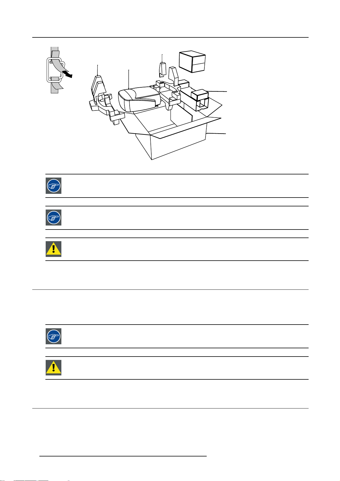
The projector is packed in a carton box. To provide protection during transpor
package is secured with banding and fastening clips.
To unpack
1. Release the fastening clips. (image 1-1)
2. Remove the banding. Handle as shown in the drawing.
3. Take the projector out of its shipping carton and place it on a table. (image 1-2)
tation, the projector is surrounded with foam. The
R5976491 IQ PRO G 210L/350/500 20122003
5
Page 12
1. Packaging and Dimensions
8
R824562
PULL
TO OPE
Image 1-1
Image 1-2
Save the original shipping carton and packing material, they will be necessary if you ever have to ship your
projector. For maximum protection, repack your projector as it was originally packed at the factory.
IQ
R824561
R824518
R825784
(+ cable basket R72440
Save the original shipping carton and packing material, they will be necessary if you ever have to ship your
projector. For maximum protection, repack your projector as it was originally packed at the factory.
Never transport the projector with the lens mounted on it !
Always remove the lens before transporting the projector.
1.3 Lens Packaging
Way of Packaging
Lenses are supplied as an individual item.
Theyarepackedinacartonbox.
Save the original shipping carton and packing material, they will be necessary if you ever have to transport
e lens.
th
Never transport the projector with the lens mounted on it !
Always remove the lens before transporting the projector.
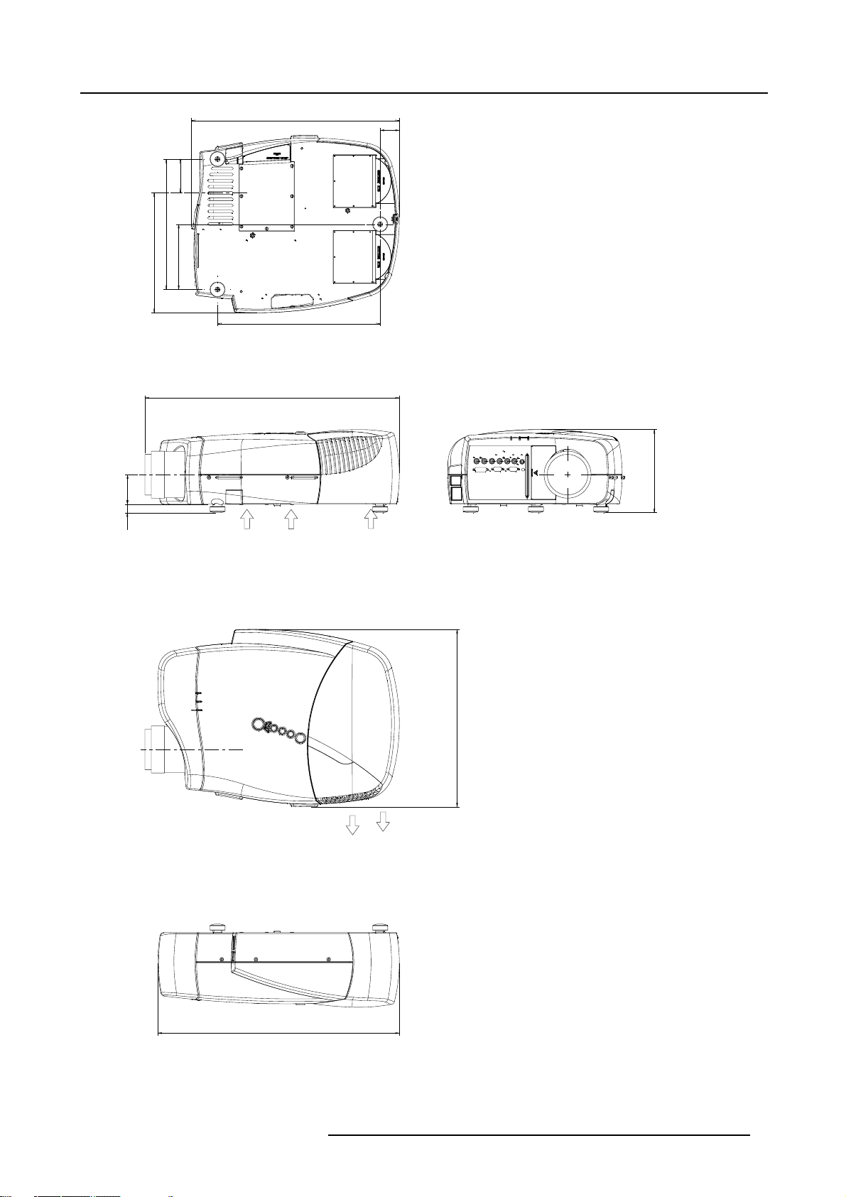
1.4 Dimensions
Dimensions overview
Dimensions are given in mm (1 inch = 25.4 mm)
6
R5976491 IQ PRO G 210L/350/500 20122003
Page 13
1. Packaging and Dimensions
206
9
487
8
7
5
0
3
1
2
8
5
2
1
380
Length with different lenses, see table
45
5
9
1
Cold air in
Hot air out
5
1
4
565
Image 1-3
R5976491 IQ PRO G 210L/350/500 20122003 7
Page 14

1. Packaging and Dimensions
Lens
SVD(2-2.5:1)
QVD(1.3-1.8:1)
QVD(1.9-2.6:1)
QVD(3.0-6.0:1)
QVD(0.85:1)
QVD(7.0:1)
length of projector
545mm
600mm
590mm
620mm
545mm
540mm
combinable with cable
basket
YES
YES
YES
YES
NO
YES
Remarks
Length with cable basket = 565mm
Length with cable basket = 560mm
8 R5976491 IQ PRO G 210L/350/500 20122003
Page 15
2. INSTALLATION GUIDELINES
Overview
• Safety warnings
• Installation guidelines
• Projector configurations
• Lenses
2.1 Safety warnings
Before installing the projector, read first the safety instructions in the safety manual (R5975258) delivered with
the projector.
Insure that the projector is installed in an easy to evacuate room in case of a lamp explosion.
2.2 Installation guidelines
2. Installation Guidelines
Ambient temperature check
Careful consideration of things such as image size, ambient light level, projector placement and type of screen to use are critical to
the optimum use of the projection system.
Max. ambient temperature : 40 °C or 104 °F
Min. ambient temperature : 0 °C or 32 °F
The projector will not operate if ambient air temperature falls outside this range (0°C- 40°C or 32°F-104°F).
Environment
Do not install the projection system in a site near heat sources such as radiators or air ducts, or in a place subject to direct sunlight,
excessive dust or humidity. Be aware that room heat rises to the ceiling; c
excessive
Harmful Environmental Contamination Precaution
heck that temperature near the installation site is not
Environment condition check
A projector must always be mounted in a manner which ensures the free flow of clean air into the projectors ventilation inlets as well
as free flow at the ventilation outlets. The installati
For installations in environments where the projector is subject to airborne contaminants such as that produced by smoke machines
or similar (these deposit a thin layer of greasy residue upon the projectors internal optics and imaging electronic surfaces, degrading
performance), then it is highly advisable and desir
air supply. Devices or structures to extract or shield contaminated air well away from the projector are a prerequisite, if this is not
a feasible solution then measures to relocate the projector to a clean air environment should be considered. Make sure that the
projector never runs with dirty dustfilter
dustfilters on a regular basis and to replace them at any lamp change. Barco reserves itself the right to refuse warranty replacement
of consumables if they have been used in a projector with dirty airfilters. Only use the manufactures recommended cleaning kit which
has been specifically designed for clean
degrade optical coatings and damage sensitive optoelectronics .
Failure to take suitable precautions to protect the projector from the effects of persistent and prolonged air contaminants will culminate in extensive and irreversible ingrained optical damage. At this stage cleaning of the internal optical units will be non-effective
and impracticable. Damage of this nature is under no circumstances covered under the manufactures warranty and may deem the
warranty null and void. In such a case the client shall be held solely responsible for all costs incurred during any repair. It is the
clients responsibility to ensure at all times that the projector is protected from the harmful effects of hostile airborne particles in the
environment of the projector. The manufacture reserves the right to refuse warranty repair if a projector has been subject to wantful
neglect, abandon or improper use.
s as this will dramatically reduce the lifetime of the consumables. It is advised to clean the
ing optical parts, never use industrial strength cleaners on a projectors optics as these will
on must also allow easy access to the consumable parts ( dustfilters, lamps, ...)
able to have this contamination removed prior to it reaching the projectors clean
What about ambient light ?
The ambient light level of any room is made up of direct or indirect sunlight and the light fixtures in the room. The amount of ambient
light will determine how brig
R5976491 IQ PRO G 210L/350/500 20122003
ht the image will appear. So, avoid direct light on the screen. Windows that face the screen should be
9
Page 16
2. Installation Guidelines
covered by opaque drapery while the set is being viewed. It is desirable to install the projection system in a room whose walls and
floor are of non-reflecting material. The use of recessed ceiling lights and a method of dimming those lights to an acceptable level
is also important. Too much ambient light will ‘wash out’ of the projected image. This appears as less contrast between the darkest
and lightest parts of the image. With bigger screens, the ‘wash out’ becomes more important. As a general rule, darken the room to
the point where there is just sufficient light to read or write comfortably. Spot lighting is desirable for illuminating small areas so that
interference with the screen is minimal.
Which screen type ?
There are two major categories of screens used for projection equipment. Those used for front projected images and those for rear
projection applications. Screens are rated by how much light they reflect (or transmit in the case of rear projection systems) given a
determined amount of light projected toward them. The ‘GAIN’ of a screen is the term used. Front and rear screens are both rated
in terms of gain. The gain of screens range from a white matte screen with a gain of 1 (x1) to a brushed aluminized screen with a
gain of 10 (x10) or more. The choice between higher and lower gain screens is largely a matter of personal preference and another
consideration called the Viewing angle. In considering the type of screen to choose, determine where the viewers will be located
and go for the highest gain screen possible. A high gain screen will provide a brighter picture but reduce the viewing angle. For
more information about screens, contact your local screen supplier.
Image size
The projector is designed for projecting an image size with a screenwidth from 1.00m (3.3ft) to 6.00m (19.7ft) with an aspect ratio of
4to3.
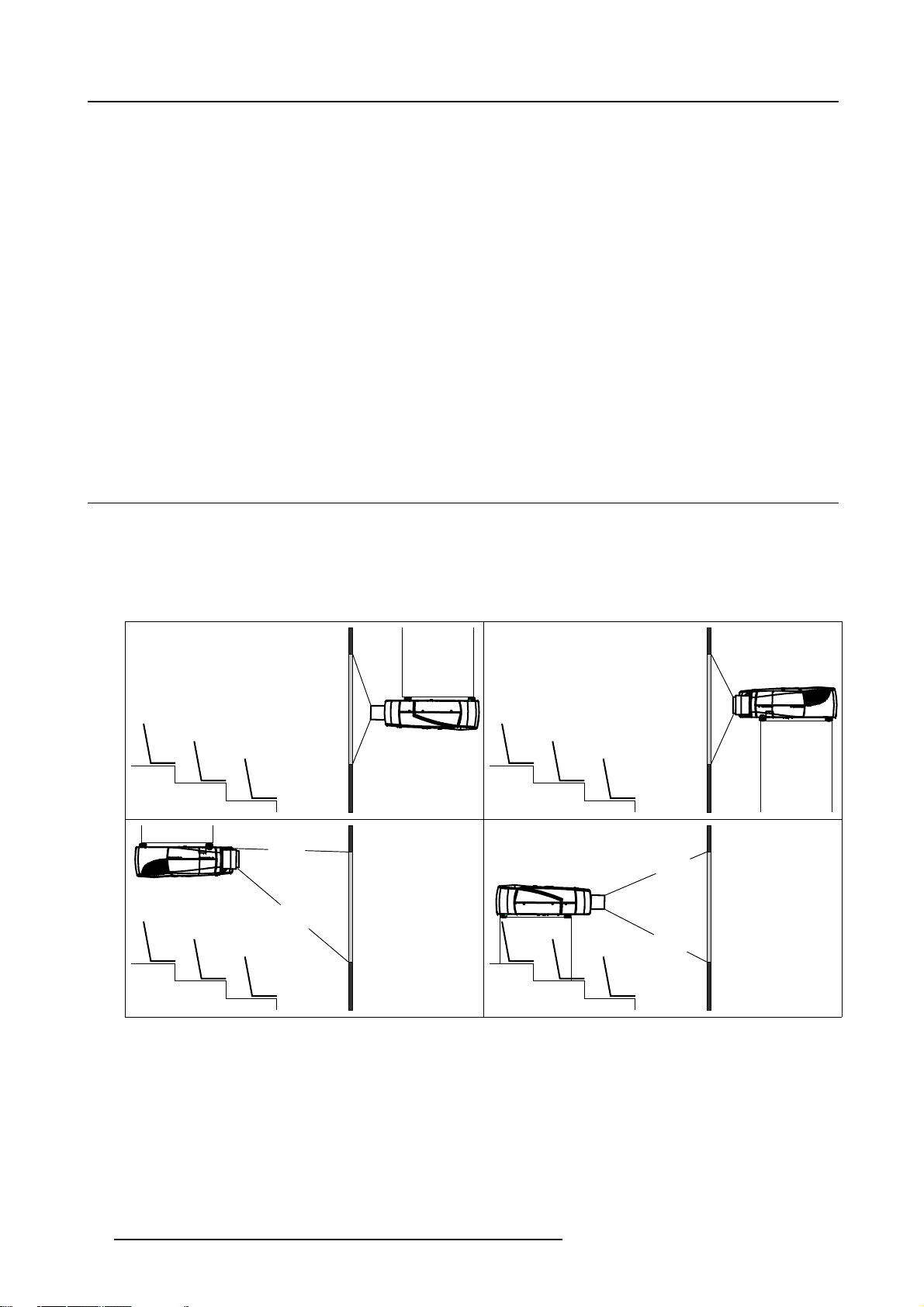
2.3 Projector configurations
The different configurations
1. Rear/Ceiling
2. Rear/Table
3. Front/Ceiling
4. Front/Table
1
3
Image 2-1
2
4
10 R5976491 IQ PRO G 210L/350/500 20122003
Page 17
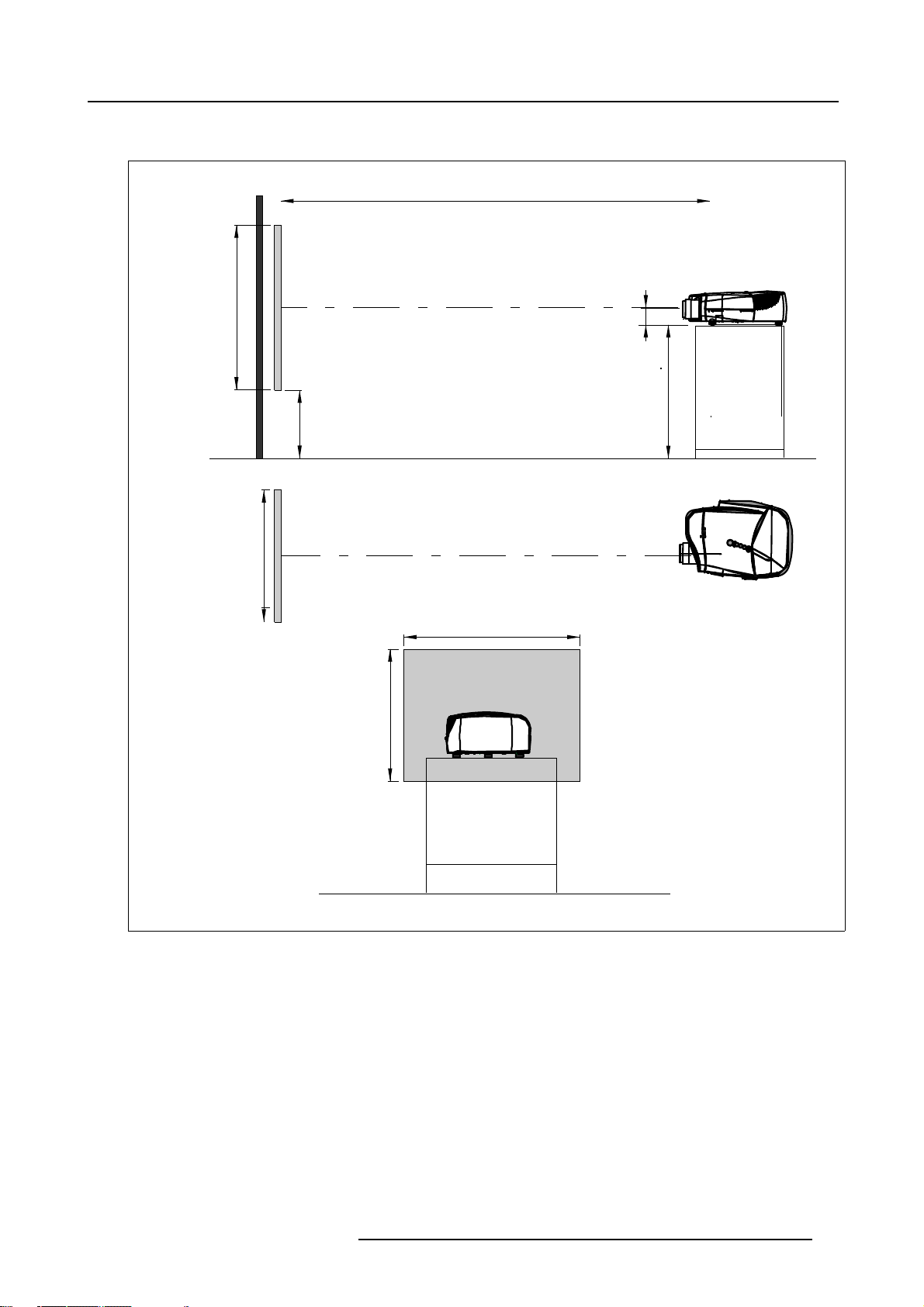
Positioning the projector
2. Installation Guidelines
PD
P
a
b
c
SH
S
B
SW
S
SH
x
A
CD=SH/2+B-A
F
SW
Image 2-2
ON-Axis installation
a side view
b top view
c back view
x optical axis projection lens
pprojector
s screen
F floor
R5976491 IQ PRO G 210L/350/500 20122003
F
11
Page 18
2. Installation Guidelines
a
SH
PD
x
P
S
A
B
CD=B-A
F
b
c
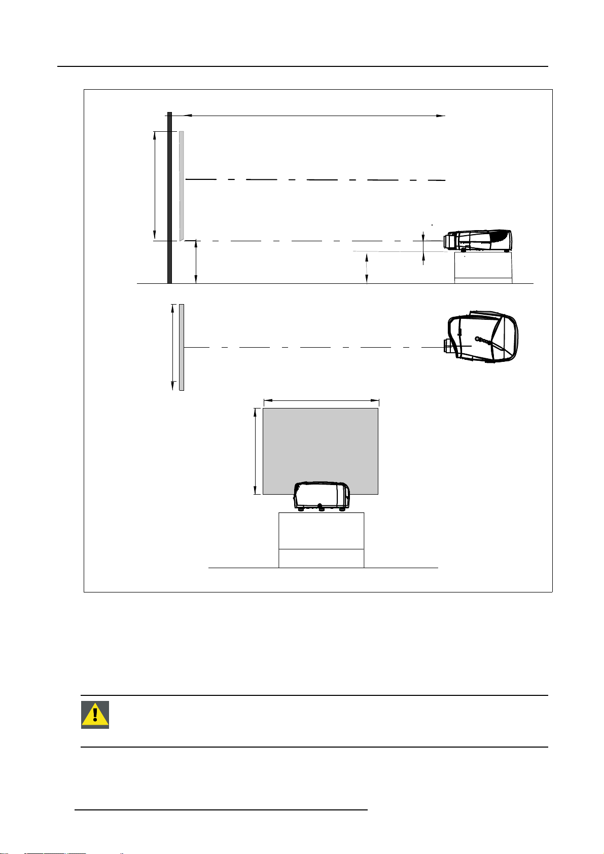
Image 2-3
100% OFF Axis installation
a side view
b top view
c back view
x optical axis projec
pprojector
s screen
F floor
SW
S
SW
SH
F
tion lens
Only for iQ Pro:
The harddisk in the IQ Pro server is formatted in horizontal position but can operate in all axes (6 directions).
The projector should not be tilted more then +/- 5 degrees from these positions, otherwise error rates will
increase.
12 R5976491 IQ PRO G 210L/350/500 20122003
Page 19
2.4 Lenses
Overview
• Lenses
• Lens formulas
• Lens installation
• Removing the lens
• Cleaning the lens
2.4.1 Lenses
Available lenses
The following lenses are available, or will become available (contact a BARCO service center) as an option :
2. Installation Guidelines
Lenses
QVD(0.85:1)
QVD(1.3-1.8:1)
QVD(1.9-2.6:1)
QVD(3.0-6.0:1)
QVD(7:1)
SVD(2.0-2.5:1)
The QVD (0.85:1) is to be used in ON Axis configuration only.
Shifting the lens vertically will not guarantee optimal image quality.
Standard version
R9841220
R9840950
R9840960
R9840970
R9841230
R9841240
2.4.2 Lens formulas
Formulas
Metric Formulas (meter) Inch formulas (inch)
QVD(0.85:1) PD = -0.034 + 0.801 x SW + 0.0086 /SW PD = -1.34 + 0.801 x SW + 13.35 /SW
QVD(1.3-1.8:1) PDmin = 0.019 + 1.216xSW + 0.028/SW
PDmax = -0.001 + 1.584xSW + 0.074/SW
PDmin = 0.75 + 1.216xSW + 43.4/SW
PDmax = -0.04 + 1.584xSW + 115/SW
QVD(1.9-2.6:1) PDmin = 0.052 + 1.731xSW - 0.014/SW
PDmax = 0.11 + 2.33xSW - 0.059/SW
QVD(3.0-6.0:1) PDmin = 0.048 + 2.795xSW - 0.042/SW
PDmax = 0.06 + 5.6xSW - 0.041/SW
QVD(7:1) PD = 0.013 + 6.35xSW + 0.005/SW PD = 0.51 + 6.35xSW + 8.35/SW
SVD(2.0-2.5:1) PDmin = -0.139 + 1.733xSW + 0.1/SW
PDmax = 0.005 + 2.224xSW - 0.00862/SW
Lens program to calculate the projector distance is available on the BARCO web site :
ttp://www.barco.com/projection_systems/customer_services/lens_program.asp
h
R5976491 IQ PRO G 210L/350/500 20122003 13
PDmin = 2.05 + 1.731xSW - 21.7/SW
PDmax = 4.33 + 2.33xSW - 91.8/SW
PDmin = 1.89 + 2.795xSW - 65/SW
PDmax = 2.36 + 5.6xSW - 63.4/SW
PDmin = -5.47 + 1.733xSW + 153/SW
PDmax = 0.2 + 2.224xSW - 13.3/SW
Page 20
2. Installation Guidelines
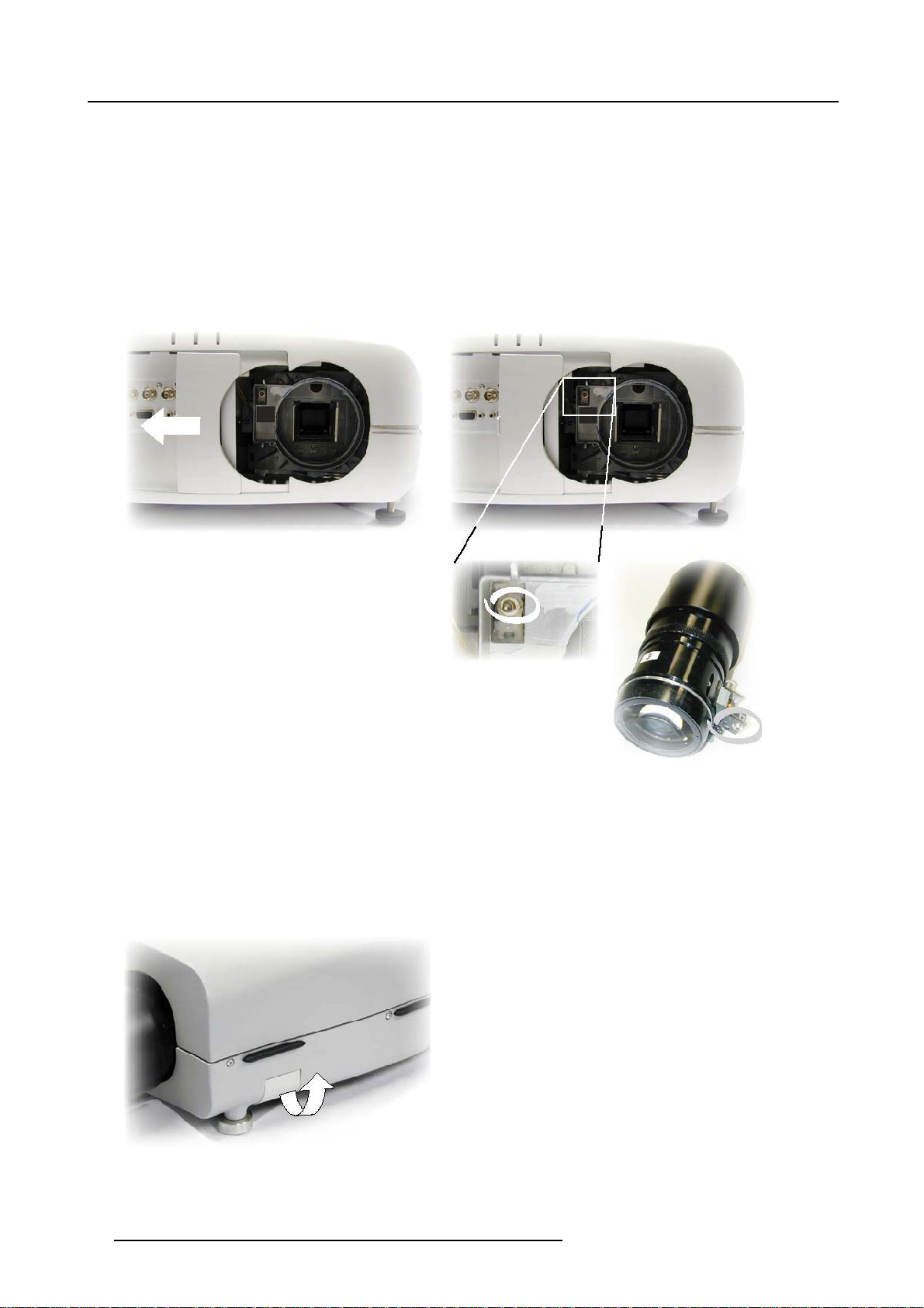
2.4.3 Lens installation
How to install ?
1. Take the lens out of its packing material
2. Slide the lensdoor to the left (image 2-4)
3. Fix the lens by placing it in the housing
Note: In case of a motorized lens the female jack must be in front o f the male jack located inthe upper-left part of the housing
in the projector (image 2-5)
4. Push carefully to lock the lens in the housing
5. Slide back the lensdoor to the right
Image 2-4
Image 2-5
.4
2.4
How
1. Slide the lens door to the left.
2. Unlock the lens by pulling the handle located on the right side of the projector (image 2-6)
3. Remove the lens out of its housing
oving the lens
Rem
to remove the lens ?
Image 2-6
14 R5976491 IQ PRO G 210L/350/500 20122003
Page 21
Never transport the projector with the lens mounted on it !
Always remove the lens before transporting the projector.
2.4.5 Cleaning the lens
To minimize the possibility of damaging the optical coating or scratching exposed lens surface, we have developed recommendations for cleaning the lens. FIRST, we recommend you try to remove any material from
the lens by blowing it off with clean, dry deionized air. DO NOT use any liquid to clean the lenses.
Necessary tools
To ra ys e eTMcloth (delivered together with the lens kit). Order number : R379058.
Howtocleanthelens?
Proceed as follow :
TM
1. Always wipe lenses with a CLEAN Toraysee
2. Always wipe lenses in a single direction.
Warning: Do not wipe back and forwards across the lens surface as this tends to grind dirt into the coating.
3. Do not leave cleaning cloth in either an open room or lab coat pocket, as doing so can contaminate the cloth.
4. If smears occur when cleaning lenses, replace the cloth. Smears are the first indication of a dirty cloth.
cloth.
2. Installation Guidelines
Do not use fabric softener when washing the cleaning cloth or softener sheets when drying the cloth.
Do not use liquid cleaners on the cloth as doing so will contaminate the cloth.
Other lenses can also be cleaned safely with this TorayseeTMcloth.
R5976491 IQ PRO G 210L/350/500 20122003 15
Page 22

2. Installation Guidelines
16 R5976491 IQ PRO G 210L/350/500 20122003
Page 23
3. CONNECTIONS
Overview
• Power connection
• Input source connection
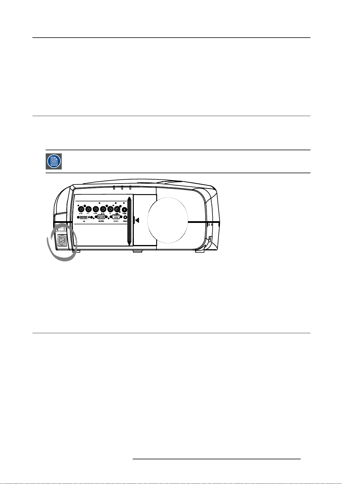
3.1 Power connection
AC power (mains) cord connection
Use the supplied power cord to connect your projector to the wall outlet.
Plug the female power connector into the male connector at the front of the projector.
The power input is auto-ranging from 90 to 240 VAC.
3. Connections
I
0
Image 3-1
Fuses
For continued protection against fire hazard :
• refer replacement to qualified service personnel
• ask to replace with the same type of fuse.
3.2 Input source connection
Overview
• Input section
• Input facilities
• 5-Cable input
• Composite Video Input
• S-Video input
• Digital Visual Interface (DVI) input
• Computer input
• Communications Connections
• Extended configuration
3.2.1 Input section
Input Layers
The input section is divided in layers, each of t
R5976491 IQ PRO G 210L/350/500 20122003
hem regrouping several inputs.
17
Page 24
3. Connections
1. Layer 1: analog layer containing analog data and video inputs
2. Layer 2: a hybrid layer containing 2 digital and 1 analog input
3. Layer 3 : network layer
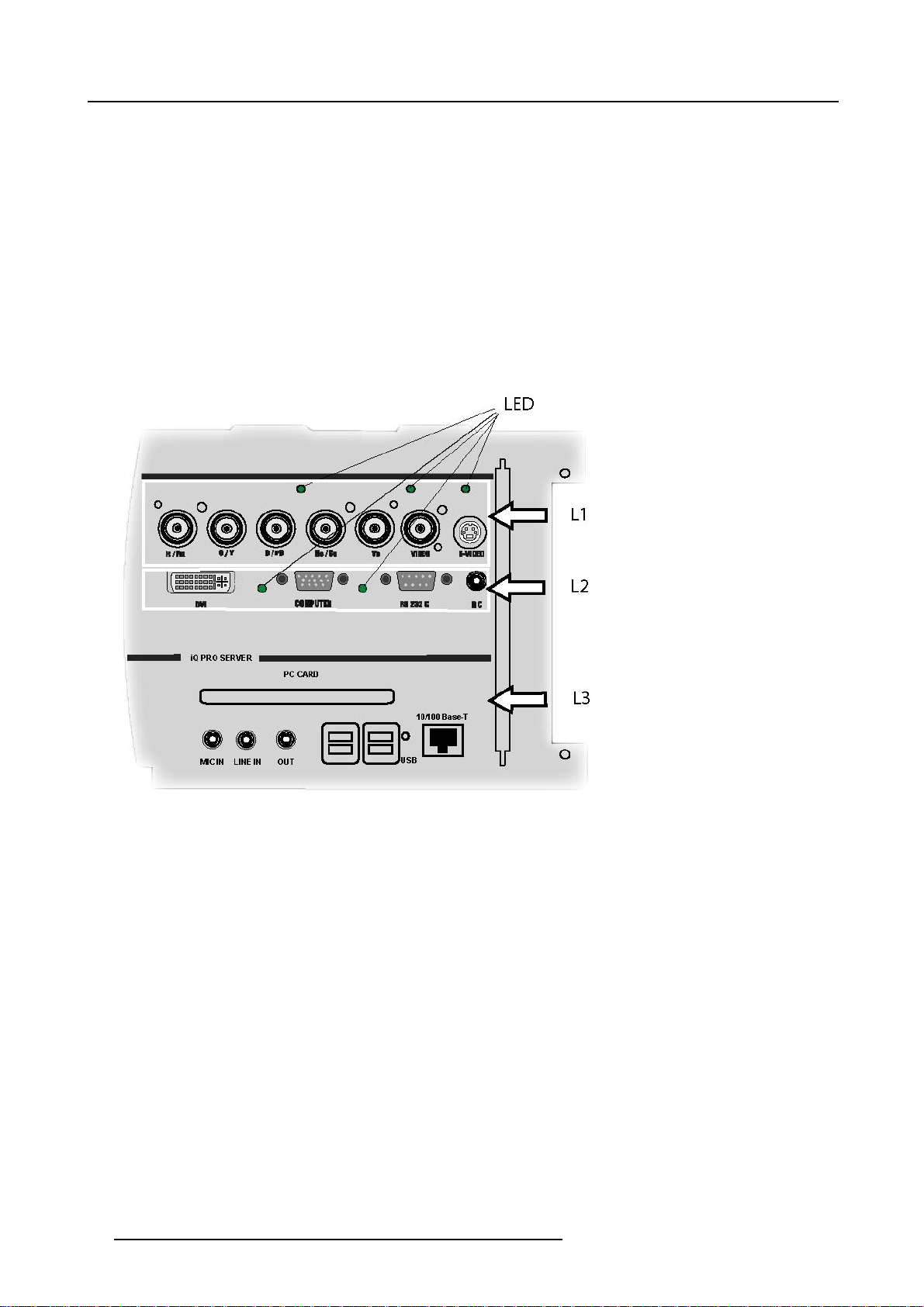
3.2.2 Input facilities
overview
• 5–cable input
• composite video
• component video (PR/Y/PB)
•S-Video
• Digital Visual Input (DVI)
• Computer
• network interface
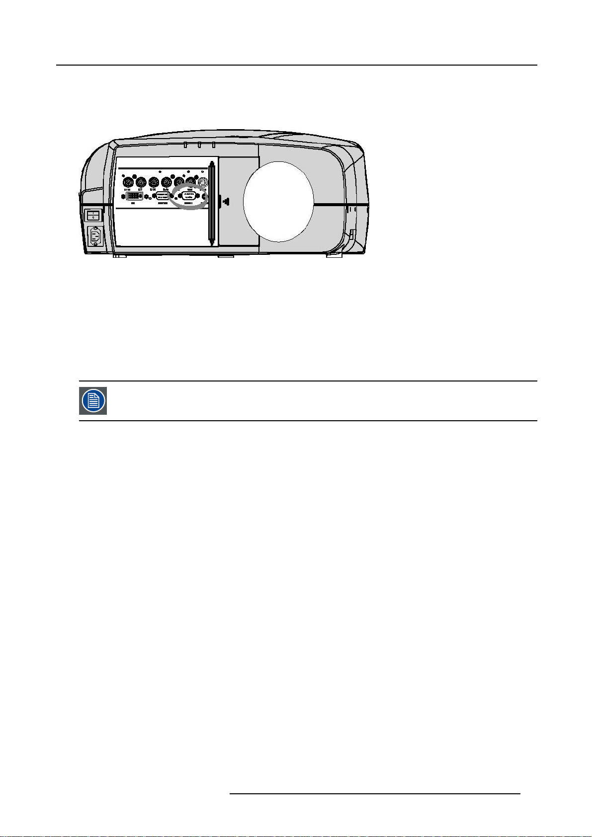
Image 3-2
Source input section, the LED’s indicate the selection of a signal.
L1 Layer 1 = RGBHV (data) + Composite Video + S-Video
L2 Layer 2 = DVI + Computer + RS232 IN + RC (Wired Remote Control)
L3 Layer 3 = network Layer = Mic IN + Line IN + PC Card slot
18
+4xUSBin+RJ45
R5976491 IQ PRO G 210L/350/500 20122003
Page 25
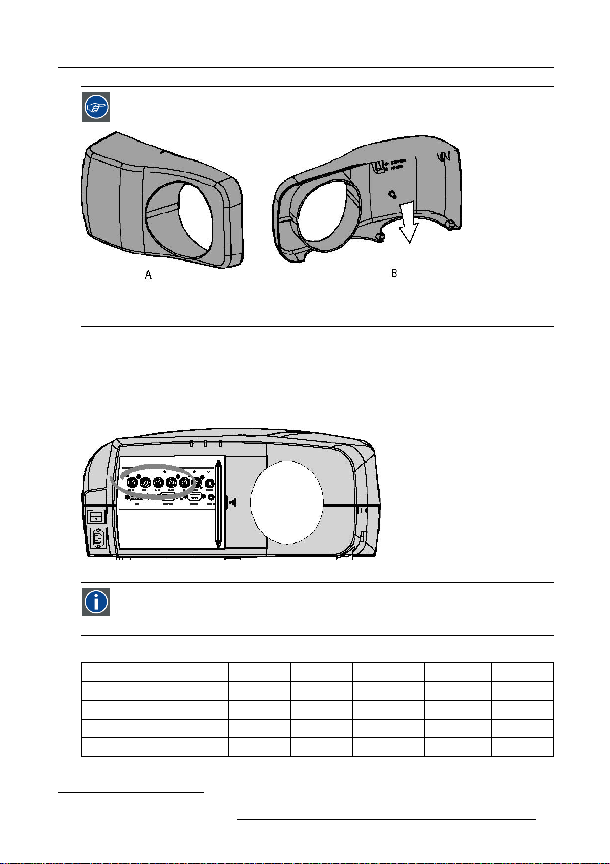
A cable cover is supplied with the projector and can be fitted on the front of the projector
Image 3-3
Cable basket : the white arrow shows the cables leaving the projector
A Front view
B Back view
3.2.3 5-Cable input
3. Connections
Input specifications
The 5-cable input section is made of 5 BNC input terminals.
0.7 Vpp ± 3dB
75 Ω terminated
Image 3-4
Component Video
In Component Video the term component descr
ture, these components are PR/Y/PB. A composite video signal on the other hand contains all the information needed
for the color picture in a single channel of information
Which signals can be connected ?
ibes a number of elements that are needed to make up the video pic-
Signals/Input BNC
RGBHV
RGsB
RGBS
Component
1. data or video
R
R
1
1
R
R
G
G
G
s
G
PR Y PB
B H V
B H V
B
B
- -
S
- -
-
R5976491 IQ PRO G 210L/350/500 20122003 19
Page 26
3. Connections
Beside the standard RGB, component and sync signals, the extended mode of the 5 Cable input makes processing of additional signals possible.
How to select a source on the 5 cable input ?
1. Press 1 on the RCU
Note: Ano ther way for selecting this input is via Source on the local keypad or via the Menu
Component Video signals (PR/Y/PB)
Some interfaces use progressive output signals with a double line frequency of 32 kHz. The video decoder
used for the video signals is not appropriate for these signals since it can only handle 16 kHz signals. This
signal has therefore to be internally redirected, this is done in the Source selection menu by selecting Data on
BNC’s instead of Component video and by selecting Cr/Y/Cb in the advanced settings of the Image file m
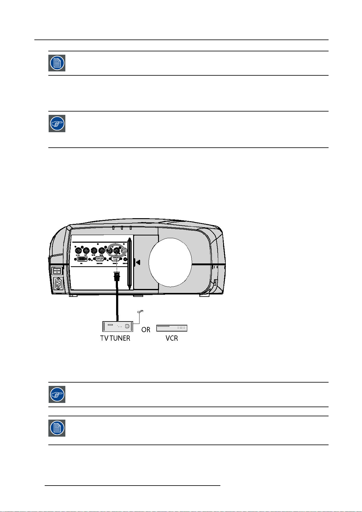
3.2.4 Composite Video Input
Input specifications
The Composite video input section is made of 1BNC input terminal.
1.0 Vpp ± 3dB
75 Ω terminated
No loop through
enu.
Image 3-5
How to select a Composite Video Input ?
1. Press 3 on the RCU
Note: Ano ther way for selecting this input is via Source on the local keypad or via the Menu.
The projector allows the input of more composite video signals (up to 7 composite video signals).
5 cable extended configuration, page 23
This note is only valid for standard iQ version (not for the iQ Pro version)
The Audio&Video optional layer(3) allows the use of an additional Video BNC input (referred to as Video2).
The selection of this optional input ha
20 R5976491 IQ PRO G 210L/350/500 20122003
ppens the same way as the standard input (key 3)
Page 27
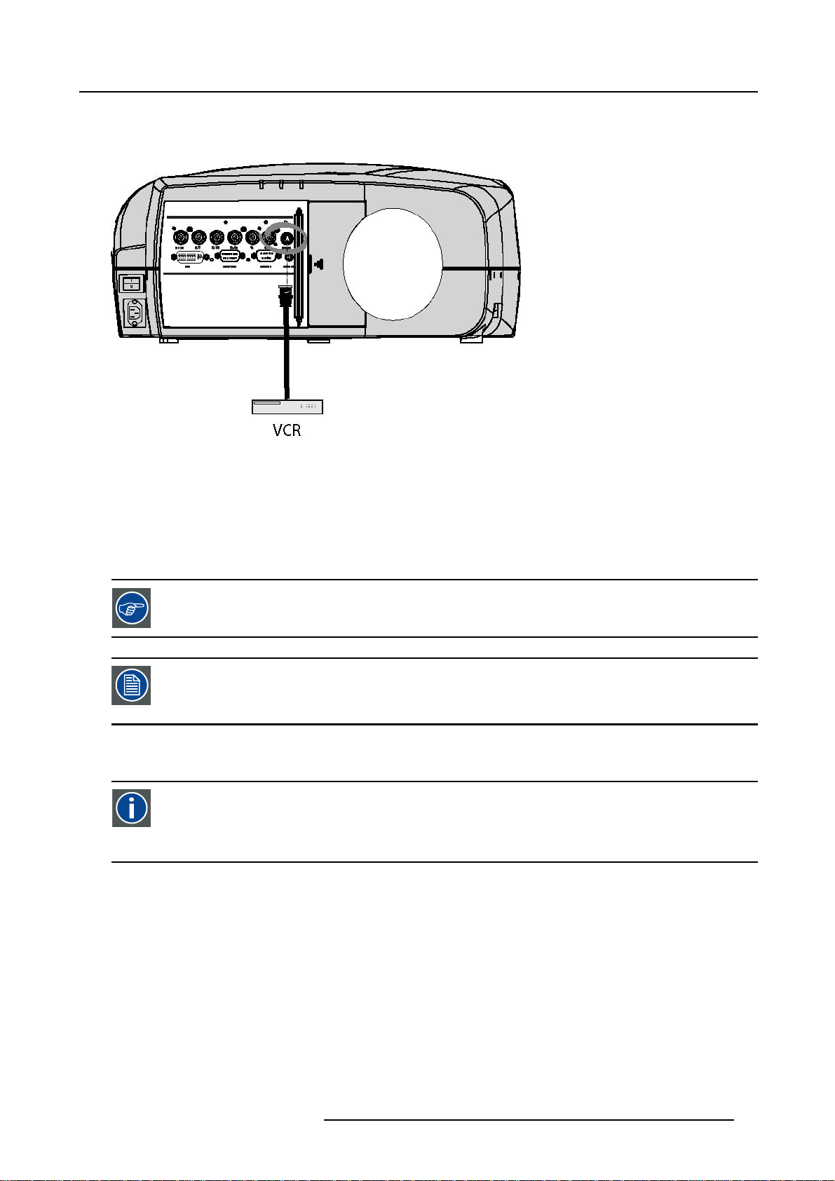
3.2.5 S-Video input
Input specification
Image 3-6
Which signal can be connected ?
Standard S-Video (S-VHS) with separate Y(luma) and C (chroma) signals.
3. Connections
How to select the S-Video input ?
1. Press 4 on the RCU
Note: Ano ther way for selecting this input is via Source on the local
The projector allows the input of more S-Video signals (up to 3
S-Video extended configuration, page 24
This note is only valid for standard iQ versions (not for the iQ Pro version)
The Audio&Video optional layer(3) allows the use of a
The selection of this optional input happens the same way as the standard input (key 4)
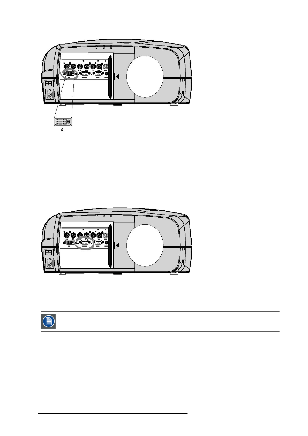
3.2.6 Digital Visual Interface (DVI) input
DVI
Digital Visual Interface is a display interface developed in response to the proliferation of digital flat panel displays. It
uses a high speed serial interface with TMDS (Transition Minimized Differential Signaling) to send data to the display.
DVI can be single or dual link.
Input specifications
Single link DVI
Differential input voltage: 200 mV - 800mV
keypad or via the Menu.
composite video signals).
n additional S-Video input (referred to as S-Video4).
R5976491 IQ PRO G 210L/350/500 20122003
21
Page 28
3. Connections
Image 3-7
a DVI-I type connector analog link (4 pins at the right side of the connector) not supported
How to select the DVI Input ?
1. Press 5 on the RCU
Note: Ano ther way for selecting this input is via Source on the local keypad or via the Menu.
3.2.7 Computer input
Input specification
TTL sync input : U
RGB input = 0.7 V
Image 3-8
min
pp
=2.0V
±3dB
What can be connected ?
•RGBHV
•RG
B
S
CompositesynconlypossibleonGreen
How to select a computer input ?
1. Press 2 on the RCU
Note: Ano ther way for selecting this input
3.2.8 Communications Connections
Overview
• RS232 IN connection
22
is via Source on the local keypad or via the Menu.
R5976491 IQ PRO G 210L/350/500 20122003
Page 29
3.2.8.1 RS232 IN connection
What can be connected to the RS232 IN connection ?
The RS 232 IN connections allows the projector to communicate with a Computer e.g. IBM PC or Apple Macintosh.
Image 3-9
Applications of the RS232 connection
Remote control:
• easy adjustment of projector via IBM PC (or compatible) or MAC connection.
• address range from 1 to 255
• allow storage of multiple projector configurations and set ups.
• wide range of control possibilities
Data communication: sending data to the projector or copying the data from the projector to the computer
3. Connections
To set up the baudrate of the projector, see the Installation menu
3.2.9 Extended configuration
Overview
• Introduction
• 5 cable extended configuration
• S-Video extended configuration
• Summarizing
3.2.9.1 Introduction
What can be done ?
The PiP mode allows to display up to 4 windows of images coming from different sources. The extended capabilities on the input
board allow therefore to combine several data & video sources, beside that, they allow switching between a wide range of input
signals.
3.2.9.2 5 cable extended configuration
What can be done ?
Beside the standard RGB, composite & sync signals, the extended capabilities of the 5 cable inputs make treatment of additional
signals possible:
• a composite video signal may be connected to 4 of the 5 BNC’s (beside the standard video BNC input)
• a S-Video signal can be connected
R5976491 IQ PRO G 210L/350/500 20122003
23
Page 30
3. Connections
Inputs
R
Signals
RGBHV
RGSB
RGBS
Component
S-Video
R
R
R
PR Y PB
- - - -
S-Video C
Composite VIDEO
Composite
Composite
Composite
Composite
Table 3-2
Extended configuration of the 5 cable input: the first column gives the possible signals, and the first row the 5 cable input connectors (+ the standard Video BNC).
-
- -
- - - -
- - - - -
G
G
G
S
G
-
- - - - -
VIDEO
B H V
B H V
B
B
- - -
S
- -
- - -
C
Y
- - -
- - - -
VIDEO
- - -
VIDEO
How to set up the 5 cable extended configuration ?
1. Connect the video or S-video source to the desired BNC connector
Note: In some cases an adapter cable is required (image 3-10, image 3-11, image 3-12)
VIDEO
-
Y
VIDEO
Image 3-10
Connecting an S-Video signal on the Vs
Video BNC
Image 3-11
Connecting an S-Video signal on the R & B
&
BNC
Image 3-12
Connecting composite Video signals on the
5 cable input
Multiple video signals can not be visualized simultaneously since there is only one decoder. However, the
use of the optional Audio & video layer(3) allows to visualize up to 2 different video signals (in PiP mode, see
"Introduction to PiP", page 72).
3.2.9.3 S-Video extended configuration
What can be done ?
Beside the standard luminance (Y) and chrominance (C) signals, the advanced capabilities of the S-Video input make treatment of
additional signals possible:
• 2 composite video signal may be connected.
Inputs
Y
Signals
S-Video
Composite Video
Composite Video
Table 3-3
Extended configuration of the S-Video input: the first column gives the possible signals, and the first row the S-Video inputs pins.
Y
Video
-
C
C
-
Video
24 R5976491 IQ PRO G 210L/350/500 20122003
Page 31

How to set up the S-Video extended configuration ?
1. Connect the video sources to the desired connector (image 3-13)
Note: An adapter ca ble is required
Image 3-13
Connecting 2 composite Video signals on the S-Video connector
3. Connections
Multiple video signals can not be visualized simultaneously since there is only one decoder. However, the
use of the optional Audio & video layer(3) allows to visualize up to 2 different
"Introduction to PiP", page 72).
video signals (in PiP mode, see
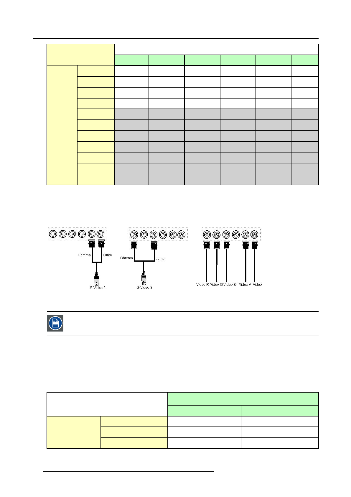
3.2.9.4 Summarizing
Summarizing the extended connections
A composite video signal can be entered via 7 different inputs, whic
optional video input):
1. Video R : via 1st BNC
2. Video G : via 2nd BNC
3. Video B : via 3rd BNC
4. Video VS : via 5th BNC
5. Video : via the standard composite video BNC input
6. Video Y : via S-Video input
7. Video C : via S-Video input
Key 3 on the RCU allows to browse through the active video inputs, each hit moves to the next active video input. The first hit on
key 3 selects the last selected video input.
In the same way 3 S-Video signals can be visualized through 3 different inputs
1. S-Video 1: via the standard S-Video input
2. S-Video 2 : via the 5 the BNC and the standard Composite Video input
3. S-Video 3 : via the 1st and the 3rd BNC
h gives us 7 different video signals (not including
Key 4 on the RCU allows to browse through the active S-Video inpu
key 4 selects the last selected video input.
R5976491 IQ PRO G 210L/350/500 20122003
ts, each hit moves to the next active video input. The first hit on
25
Page 32

3. Connections
26 R5976491 IQ PRO G 210L/350/500 20122003
Page 33

4. GETTING STARTED
Overview
• RCU & Local keypad
• Terminology overview
• Switching on
• Lamp runtime
• Lamp error
• Quick set up adjustments
• Projector address
• Controlling the projector
• Digital Zoom
• Menu structure
• Using the menu
• Using the Dialogboxes
4.1 RCU & Local keypad
How controlling the projector ?
The projector can be controlled by the local keypad or by the remote control unit.
4. Getting started
Location of the local keypad ?
The local keypad is located on the topside of the projector.
For key overview: Terminology overview, page 29
R5976491 IQ PRO G 210L/350/500 20122003
27
Page 34

4. Getting started
Image 4-1
Local keypad layout
Remote control functions.
This remote control includes a battery powered infrared (IR) transmitter that allows the user to control the projector remotely. This
remote control is used for source selection, control, adaptation and set up. It includes automatic storing of picture controls (Brightness, Sharpness...) and settings.
Other functions of the remote control are :
• switching between stand by and ope
• switching to "pause" (blanked picture, full power for immediate restarting)
• direct access to all connected sources.
rational mode.
Diagnose LED’s
Green
LED1
LED2
LED3 IR acknowledgement continue : standby
cool down sequence: flickers 60 seconds (120
seconds in case of 400 series) after switching to
standby
only for iQ Pro: shows when projector is in
standby and server is actif.
Red
rescue program (software error)
hardware error
flickers : Security = ON
28 R5976491 IQ PRO G 210L/350/500 20122003
Page 35

4.2 Terminology overview
Overview
The following table gives an overview of the different functionalities of the keys.
4. Getting started
Image 4-2
1 Function keys
2 MENU Menu key, to enter or exit the Toolbar menu.
3 Address key
4
LOGO key allows to recall the stored Logo (not in PiP mode)
5
PAU SE to stop projection for a short time, press ’PAUSE’. The image disappears but full power is
6
STBY standby button, to start projector when the power switch is switched on and to switch off the
7
MUTE
8
AUTOIMAGE Auto image, to center the image on the active LCD surface.
9 Digit buttons direct input selection.
9b
SOURCE button this button allows to switch through the active (scanned) inputs
R5976491 IQ PRO G 210L/350/500 20122003 29
user programmable keys with functions for direct access.
(recessed key), to enter the address of the projector (between 0 and 9). Press the recessed
address key with a pencil, followed by pressing one digit button between 0 and 9.
retained for immediate restarting.
projector without switching off the power switch.
Attention : Switching to Standby. When the projector is running and you want to
go to standby, press the standby
to interrupt the sound reproduction (audio = optional.
key for 2 seconds.
Page 36

4. Getting started
10 Lens control
11
VOL use this button to obtain the desired sound level (audio = optional)
12 Picture controls use these buttons to obtain the desired picture analog level.
13
DIGI ZOOM allows a digital Zoom of a part of the image
14 FREEZ
15 PIP
16 ENTER
17
Cursor keys Cursor Keys on RCU or on the local keypad : to make menu selections or to access the
18
BACK to leave the selected menu or item (go upwards to previous menu).
19
EFFECTS
20
PIP ADJUST allows to select a PiP window and change its configuration on screen
21
RC operating indication lights up when a button on the remote control is pressed. (This is a visual indicator to
22 IR receiver IR receiver
Table 4-2
use these buttons to obtain the desired ZOOM, SHIFT, FOCUS.
press to freeze the projected image.
allows to activate the PICTURE IN PICTURE mode
to confirm an adjustment or selection in the MENU.
On the local keypad the ENTER button additionally accesses the PIP window resize function
toolbar.
not yet implemented
check the operation of the remote control)
ordernumber RCU: R763794K
4.3 Switching on
How to switch on.
1. Press the power switch to switch on the projector.
- When ’0’ is pushed in, the projector is switched off.
- When ’1’ is pushed in, the projector is switched on
The projector starts in standby mode, LED3 is red.
Starting image projection.
1. Press Standby key once on the local keypad or on the remote control.
It may take about 60 seconds before image projection, i.e. no projection until the completion of several operations (software initialization,...).
If the Security mode is enabled,
Installation menu
a textbox will be displayed for PIN code entry, see Security settinginthe
4.4 Lamp runtime
x
To generalize for the different projector types, x refers here to the maximum run time of the lamp.
30 R5976491 IQ PRO G 210L/350/500 20122003
Page 37

4. Getting started
Lamp runtime indication while running
Independently of the lamp mode, when the total runtime of an active lamp (lamp1 for example) is (x-30) hours or more, a warning
message will be displayed.
Image 4-3
Lamp runtime management
A single mode
B dual mode
x maximum lamp runtime
Image 4-4
warning message in case of an iQ300 projector
This warning message will be repeated at the next start up. Press BACK or MENU to remove the message.
The total lifetime of the lamp for a safe operation is “x” hours max, do not use it longer. Always replace with a same type of lamp.
Call a BARCO authorized service technician for lamp replacement.
iQ Pro x(Maxlampruntime,inhours)
210L 6000
350 3000
500 1000
Table 4-3
Maximum runtime for the different iQ Pro projectors
When the lamp runtime reaches “x” hours the projector switches automatically to the other lamp, being lamp2.. following messages
are displayed during and after switching.
R5976491 IQ PRO G 210L/350/500 20122003
31
Page 38

4. Getting started
Image 4-5
Image 4-6
When lamp2 at its turn reaches x-30 hours, a warning message appears on the screen.
Image 4-7
warning message in case of a IQ300 series projector
At the end of the lifetime of lamp2 (x hours) the projector generates an alert message.
Image 4-8
A countdown time of 4 minutes is triggered before the projector is shut down (standby).
If the lamp runtime has not been reset, the alert message will reappear at the next start up (with again 4 minutes countdown time).
This alert message can be escaped with MENU or BACK, but the countdown continues.
Contact a qualified Barco technician for lamp replacement.
In Dual mode the lamp end of lifetimes are reached at the same time, however if in dual lamp mode one lamp
has been used m
ore than the other (for example if the projector has been working temporarily in single mode),
one lamp will reach its end of lifetime sooner than the other lamp, which brings us to the Single mode operation.
Using a lamp for more than x hours is dangerous as the lamp could explode.
The lamp runtime reset as well as the lamp replacement can only be done by a Barco authorized technician.
4.5 Lamp error
What happens in case of a lamp error ?
When a lamp error occurs in dual mode, a dialogbox is displayed informing the user of the steps to be taken.
Image 4-9
The message will dissapear after 2 minutes, it can also be escaped.
32
R5976491 IQ PRO G 210L/350/500 20122003
Page 39

4. Getting started
The projector will switch to single lamp mode and displays an icon (right top corner of the screen) representing a crossed out lamp,
that way informing the user of an earlier lamp error.
The icon can always be removed via the Clear lamp error function in the Lamp menu.
In case of lamp error contact a Barco authorized technician.
4.6 Quick set up adjustments
Overview
• Quick lens Adjustment
•UsingtheRCU
4.6.1 Quick lens Adjustment
What can be done ?
For a quick lens set up and image shift, use the RCU dedicated keys or the lens button on the local keypad
Zoom/focus are only available for motorized lenses.
Quick zoom/focus adjustment
1. Press LENS ZOOM or
LENS FOCUS on the RCU
2. Use the arrow keys to adjust
Quick shift adjustment
1. Press LENS SHIFT
2. Use the arrow keys to adjust
4.6.2 Using the RCU
Pointing to a reflective screen
1. Point the front of the RCU to the reflective screen surface. (image 4-10)
Image 4-10
R5976491 IQ PRO G 210L/350/500 20122003 33
Page 40

4. Getting started
When using the remote control, make sure you are within the effective operating distance.
The operating distance may be up to 15 m (50ft).
The remote control unit will not function properly if strong light strikes the sensor window or if there are
obstacles between the remote control and the IR sensor.
How to connect ?
1. Plug one end of the remote cable in the connector on the bottom of the RCU.
2. Plug the other end in the connector in the front panel of the projector labelled RC.(image4-11)
Image 4-11
Specifications of the RC input
Uin=9V
=80mA
I
max
Internal IR receivers can be disabled:
• monojack:onpluginofthejack
• stereo jack : on plug in or using an external switch bringing the right channel (B) to ground level.
AB C
D
Image 4-12
Stereo jack pin configuration
A tip: Left channel
B ring: right channel
C screen: common (GND)
D external switch
The Remote connection uses a standard two wire cable terminated on each end with a 3.5 mm male
(mono/stereo) phone jack.
This cable is not delivered but is available in most electronical or audio shops.
34 R5976491 IQ PRO G 210L/350/500 20122003
Page 41

4. Getting started
4.7 Projector address
Overview
• Address setting
• Displaying and Programming addresses into the RCU
4.7.1 Address setting
Projector address
Address installed in the projector to be individually controlled.
Common address
Default address. Projector will always execute the command coming from a RCU programmed with that common
address.
Why a projector address ?
As more than one projector can be installed in a room, the separate projector should be separately addressable with an RCU or
computer. Therefor each projector has its own address.
Set up an individual Projector Address.
The set up of a projector address can be done via the software.
Projector controlling.
Every projector requires an individual address between 0 and 255 which can be set in the Installation menu.
Whentheaddressisset,theprojectorcanbecontrolledby:
• RCU for addresses between 0 and 9.
• computer, e.g. IBM PC (or compatible), Apple MAC, etc. for addresses between 0 and 255.
A projector will respond to a RCU set to the common address ’0’ regardless of what address is set in the projector itself (common
address of projector should also be “0” ).
The RCU is default programmed with address 0 , ’common address’.
If it is necessary to control a specific projector, then enter the projector a
address is between 0 and 9). The projector with the corresponding address will listen to that specific RCU.
Some projectors may operate in domestic environments where other equipments may listen to the common
address “0” , therefore the common address can also be set to “1”.
ddress into the RCU (only when that
4.7.2 Displaying and Programming addresses into the RCU
Displaying the Projector Address on the Screen.
1. Press the Address key (recessed key on the RCU) with a pencil.
The projector’s address will be displayed in a ’Text box’
To continue using the RCU with that specific address, it is necessary to enter the same address with the
digit buttons (address between 0 and 9) within 5 seconds after pushing the address key. For example : if the
Address key displays projector address 003, then press "3" digit button on the RCU to set the RCU’s address
to match the projector’s address. Do not press 0–0–3 . This will address the remote control to ’0’ and control
all projectors in the room. If the address is not entered within 5 seconds, the RCU returns to its default address
(zero address) and controls then all projectors in the room.
Address 0 (or 1) should always allow communication
R5976491 IQ PRO G 210L/350/500 20122003 35
with the projector since it is a common address.
Page 42

4. Getting started
Displaying the Projector Address in Standby.
1. Press the Address key (recessed key on the RCU) with a pencil.
All the LED’s on the front of the projector go out.
Then LED1 starts blinking green the number of hundreds. After that LED2 starts blinking the number of tens. Finally LED3 starts
blinking green the number of units. If this is done, the original status of the leds is restored.
4.8 Controlling the projector
Input Selection
Key in the corresponding slot number with the digit keys on the RCU. The selected source will be displayed.
Picture Controls
When an image control is pressed, a text box with a bar scale, icon and function name of the control, e.g. ’brightness...’ appears
on the screen (only if Textbox in the Installation menu is ON). The length of the bar scale and the value of the numeric indication
indicate the current memorized setting for this source. The bar scale changes as the arrows on the RCU are pressed or the + or buttons on the local keypad.
The picture settings are saved in the image file.
Image 4-13
Brightness
Contrast Use the + button for a higher contrast.
Color Use the + button for richer colors.
Tint(Hue) Tint is only active for Video and S-Video when using the NTSC 4.43 or N
Sharpness Use the + button for a sharper picture.
Phase Use the + or - button to adjust the phase.
Gamma Use the + button for a higher gamma
Freeze
Use the + button for a higher brightness.
Use the - button for a lower brightness.
Use the - button for lower contrast.
Use the - button for lighter colors.
Use the + button
Use the - button.
Use the - button for a softer picture.
Use the - button for a lower gamma
Press Freeze to freeze the displayed image.
The Pause Key
When the Pause key is pressed, the image projection is stopped, a black screen will be displayed
To restart the image projection:
•PressPAUSE key
•PressBACK key
• Select a source number
TSC 3.58 system.
36
R5976491 IQ PRO G 210L/350/500 20122003
Page 43

4.9 Digital Zoom
What can be done ?
The Digital Zoom key on the RCU allows to zoom (in or out) one particular part of the image
How to Zoom ?
1. Press ← or → on the Digital Zoom key on the remote to Zoom the center of the image
A wizardbox is displayed in the lower part of the screen, follow the instructions.
Use the BACK key to undo the Zoom function.
Digital Zoom can not be performed on a logo.
4.10 Menu structure
PC like menustructure
The iQ Pro has a build in "PC like" toolbar menu which allows easy access to different param
The menu is activated by pressing MENU, it contains 2 levels depending on the type of user:
4. Getting started
eters for setting up the projector.
• Level 1: standard user
• Level 2: advanced user, level 2 is password protected, the advanced parameters are only visible when the correct password
has been entered ( factory password = "0000")
Menu items which are not applicable are greyed out.
4.11 Using the menu
Menu Layout
A grey line gives the transition between standard and advanced parameters.
The existence of a submenu is indicated by a white arrow, Settings is a submenu.
Keystone is an item of the Image menu.
Three suspension points indicate that the menuitem hides a dialogbox or a textbox.
Image 4-14
The menus inserted in this manual are of the advanced type: all the items are visible The menus seen by a
standard user on the screen will hence not correspond with the menus in the manual i.e. the advanced items
will not be visible, they will be replaced with "More..."
R5976491 IQ PRO G 210L/350/500 20122003 37
Page 44

4. Getting started
Greyed out menus or items are not available in this software version
How to pull down a menu ?
1. Use ↓ to pull down a menu
How to pull down a submenu ?
1. Use → to pull down a submenu
How to exit the submenu ?
1. Press BACK to exit a submenu
Press MENU to exit the menu
When the menu has been exited for more than 1 minute, the advanced user password has to be re-entered.
4.12 Using the Dialogboxes
How to use the dialogboxes ?
Some parameters are modified by means of a dialogbox, where selections can be made and/or values can be entered, The values
can be entered in several ways:
Entering numeric values using the numeric keys on the remote control
1. Press ENTER to activate the input field (image 4-15)
2. Key in the desired value
Image 4-15
Entering numeric values using the arrow keys on the remote control
1. Press ENTER to activate the input field.
2. Press ←or → to select the digit to be changed (image 4-16)
3. Press ↓ or ↑ to increase or decrease the value
Image 4-16
38 R5976491 IQ PRO G 210L/350/500 20122003
Page 45

Entering numeric values using the arrow keys on the local keypad
1. Press ENTER to activate the input field.
2. Press ←or → to select the digit to be changed
3. Press ↓ or ↑ to increase or decrease the value
To confirm the changes always press ENTER.
Use ↓ or ↑ to browse between the different fields.
In some cases an alphanumeric value (file name, ...) has to be entered. Use ↑ or ↓ to scroll through the character values once the input field is activated
Following characters can be browsed in this particular order:
Decimal scroll list: 0123456789
Signed decimal scroll list: 0123456789-
ASCII scrolllist:ABCDEFGHIJKLMNOPQRSTUVWXYZ0123456789+-*/&@#.;.abcdefghijklmnopqrstuvwxyz
4. Getting started
R5976491 IQ PRO G 210L/350/500 20122003 39
Page 46

4. Getting started
40 R5976491 IQ PRO G 210L/350/500 20122003
Page 47

5. SOURCE SELECTION
r
Overview
• Flowchart
• Source selection
• Composite Video
• S-Video selection
• The Video Selector
5.1 Flowchart
The source selection menu structure
Source Selection
Data on BNC's
Component Video
5. Source Selection
RG
B Video
s
PC
Composite Video
S-Video
DVI
Video
Video VS
Video R
Video G
Video B
Video Y
Video C
Video 2
S-Video 1
S-Video 2
S-Video 3
S-Video 4
SDI
IQ PC
Logo
optional featu
Video selector...
Image 5-1
flowchart of the Source selection menu
R5976491 IQ PRO G 210L/350/500 20122003 41
Page 48

5. Source Selection
5.2 Source selection
Selecting a source
The Source selection menu allows to select one of the different sources. Another method to select an input source is via the remote
control using the numeric keys or by using the local keypad.
How to select a source ?
1. Press MENU to activate the Toolbar
2. Press ↓ to Pull down the Source Selection menu (image 5-2)
3. Use ↑ or ↓ to select one of the different sources ( Press → to Pull down if the item has a submenu)
4. Press ENTER to confirm your choice
On the screen appears now the selected source.
Image 5-2
The Barco logo on the menu indicates the presence of a signal, the d
RCU.
The 3 first sources (Data on BNC’s, Component Video & RG(s)B) refer to the 5-cable input, the position of the
indication “1” will always show which BNC configuration is selected.
igit indicates the shortcut key on the
When to select “Data on BNC’s”
Select Data on BNC’s when a data signal is connected to the BNC’s
When to select “Component video” ?
Select Component video when a video signal of the ty
pe (PR/Y/PB) is connected on the BNC’s.
When to select RGsBVideo?
Select RGsB Video when an RGB video signal (15 KhZ) with Sync on green or sync on H is presented on the BNC’s.
This signal is routed to the video circuit and is projected in a Video Window.
5.3 Composite Video
How to select one of the 7 composite video inp
1. Press MENU to activate the Toolbar
2. Press ↓ to Pull down the Source Selection menu
3. Use ↑ or ↓ to select Composite video
4. Press → to Pull down the submenu
uts ?
42 R5976491 IQ PRO G 210L/350/500 20122003
Page 49

5. Source Selection
5. Use ↑ or ↓ to select one of the different video inputs (image 5-3)
Note: Video2 is an optional Video input and is only displayed in case the optional Video/Audio layer is installed.
If the extended mode is disabled, the submenu contains only 1 selection ( 2 selections if the Audio & Video option is
installed), see "The Video Selector", page 44
6. Press ENTER to confirm your choice
A white bullet indicates the selected composite video source which now appears on the screen.
Image 5-3
The composite video sources can also be selected using the video selector or via the dedicated key 3 on the
RCU. Key 3 allows to browse through the active video inputs when the extended mode is checked in Video
Selector..
5.4 S-Video selection
How to select one of the 3 S-Video inputs ?
1. Press MENU to activate the Toolbar
2. Press ↓ to Pull down the Source Selection menu
3. Use ↑ or ↓ to select S-Video
4. Press → to Pull down the submenu
5. Use ↑ or ↓ to select one of the different video inputs (image 5-4)
Note: S-Video4 is an optional Video input and is only displayed in case the optional Video/Audio layer is installed
If the extended mode is disabled, the submenu contains only 1 selection ( 2 selections if the Audio & Video option is
installed), see "The Video Selector", page 44
6. Press ENTER to confirm your choice
A white bullet indicates the selected video source which now appears on the screen.
R5976491 IQ PRO G 210L/350/500 20122003
43
Page 50

5. Source Selection
Image 5-4
The S-Video sources can also be selected using the video selector or via the dedicated key 4 on the RCU. Key
4 allows to browse through the active S-Video inputs when the extended mode is checke
5.5 The Video Selector
Video Selector
The Video Selector is a graphical interface which allows an overview of the different video inputs (Composite Video
and S-Video) and whether they are active (signal connected) or not as well as the selection of these different signals.
Video selector modes
The video selector has two modes:
• standard mode : the video selectable video inputs are the standard composite video & the S-Video input
• extended mode : several BNC connections are added and can
How to display the Video Selector ?
1. Press MENU to activate the Toolbar
2. Press ↓ to Pull down the Source Selection menu
3. Use ↑ or ↓ to select Video selector
On the screen appears a message, (image 5-5)
followed by a graphical interface (image 5-6, image 5-7)
A BNC or S-Video connector on the video selector can be in one of following conditions:
- A: connector disabled
- B: connector enabled but inactive (no video signal present on connector)
- C: connector enabled & active (video signal present on connector
- D: connector enabled active & selected
- E: connector enabled & active & focused (browser positioned on connector)
be selected as video inputs (S-Video inputs).
d in Video Selector.
MESSAGE
Scanning video inputs
Please wait ...
Image 5-5
44 R5976491 IQ PRO G 210L/350/500 20122003
Page 51

5. Source Selection
Image 5-6
A
B
C
D
E
Image 5-7
A
B
C
D
E
If the Audio/Video option is installed the Video Selector is updated with the additional Video & S-Video input
Image 5-8
How to select an input on the Video Selector ?
1. Use ←or→ to browse through the different inputs
2. Press ENTER
Use MENU or BACK to exit the Video Selector
How to disable the extended Video Selector
1. Use the arrow keys to select the Exte nded checkbox
2. Press ENTER to disable the extended mode
The standard Video Selector is displayed (image 5-9)
R5976491 IQ PRO G 210L/350/500 20122003
45
Page 52

5. Source Selection
Image 5-9
46 R5976491 IQ PRO G 210L/350/500 20122003
Page 53

6. GENERAL MENU
Overview
• Flowchart
• Pause
• Freeze
• Standby Timer
• Audio (Optional)
• Identification
6.1 Flowchart
The General menu structure
General
6. General Menu
Image 6-1
Pause
Freeze
Standby Timer...
Audio Setup
Audio
Settings
Identification...
IQ PC
optional feature
advanced item
6.2 Pause
Interrupting the image projection
With the Pause function, the image projection can be stopped, the projector remains with full power for immediate restart. The
projection is interrupted by
R5976491 IQ PRO G 210L/350/500 20122003
means of a mechanical shutter cutting the light beam.
47
Page 54

6. General Menu
How to interrupt the image projection ?
1. Press MENU to activate the Toolbar
2. Press → to select General
3. Press ↓ to Pull down the General menu
4. Use ↑ or ↓ to select Pause (image 6-2)
5. Press ENTER to activate the Pause function
A brief sound indicates that the shutter has been activated.
Image 6-2
The image projection can also be interrupted using the PAUSE key on the RCU.
To restart the image : press PAUSE
6.3 Freeze
Freezing the image
With the Freeze function, the image can be frozen.To restart the image, reuse the Freeze function or press the FREEZE button on
the remote.
Howtofreezetheimage?
1. Press MENU to activate the Toolbar
2. Press → to select General
3. Press ↓ to Pull down the General menu
4. Use ↑ or ↓ to select Freeze (image 6-3)
5. Press ENTER to activate the Freeze function
Image 6-3
TheimagecanalsobefrozenusingtheFREEZEkeyontheRCU
48 R5976491 IQ PRO G 210L/350/500 20122003
Page 55

6. General Menu
6.4 Standby Timer
Purpose of the Standby Timer
If there is no signal, and the standby timer is enabled, a dialogbox is displayed and the projector will shut down after a determined
time.
Image 6-4
The countdown time can be set in a dialog box in a range from 180 to 3600 seconds (default value = 300). The Timer can also be
disabled.
How to enable the timer ?
1. Press MENU to activate the Toolbar
2. Press → to select General
3. Press ↓ to Pull down the General menu
4. Use ↑ or ↓ to select Standby Timer (image 6-5)
5. Press ENTER to activate the function
On the screen appears a dialogbox (image 6-6)
6. Use ↑ or ↓ to select Enabled, a box surrounds the selected item, press ENTER to activate
7. Use ↑ or ↓ to browse to the input field
8. Use ←or→ , the numeric keys on the remote or the keypad to change the countdown setting
9. Press MENU or BACK to exit or to go back to the previous menu
Image 6-5
Standby timer
Enabled
Disabled
Countdown to
Image 6-6
sec
0
6.5 Audio (Optional)
Overview
• Audio Setup
• Audio Settings
R5976491 IQ PRO G 210L/350/500 20122003
49
Page 56

6. General Menu
6.5.1 Audio Setup
What can be done ?
Layer 3 allows the input of 4 audio signals, each of them can be linked to the corresponding (video or data) source signal. it is also
possible to link multiple audio signals to one video (or data) source signal, this can be useful in case of teleconferencing.
The configuration has to be done in the Audio Setup menu
Starting the Audio Setup menu
1. Press MENU to activate the Toolbar
2. Press → to select General
3. Press ↓ to Pull down the General menu
4. Use ↑ or ↓ to select Audio setup (image 6-7)
5. Press ENTER
A dialogbox is displayed (image 6-8)
- LED is red : audio input is mute
- LED is green : input is active (linked image source is selected)
- LED is orange : image source is not selected
Image 6-7
Image 6-8
How to mute an Audio channel ?
1. use the arr
2. Press ENTER
ow keys to select the desired mute box
How to link an audio input to a source ?
1. use the arrows to select the desired scroll box
2. Press ENTER to open the scroll box
3. use ↑ or ↓ to select the source
4. Press ENTER
When the source switching mode is the fade in/out mode, the audio switching will also be done using a fade
in/out effect.
50 R5976491 IQ PRO G 210L/350/500 20122003
Page 57

6.5.2 Audio Settings
Audio Settings
1. Press MENU to activate the Toolbar
2. Press → to select General
3. Press ↓ to Pull down the General menu
4. Use ↑ or ↓ to select Audio setup (image 6-9)
5. Press ENTER
A dialogbox is displayed (image 6-10)
6. Use the arrow keys to select and change the settings
Note: T he default value for the volume is 43, this corresponds to a gain factor of 1 (volume in = volume out).
Image 6-9
6. General Menu
Image 6-10
6.6 Identification
The projector’s identification screen
The identification screen displays the projector’s main characteristics
How to display the identification screen ?
1. Press MENU to activate the Toolbar
2. Press → t
3. Press ↓ to Pull down the General menu
4. Use ↑ or ↓ to select Identification (image 6-11)
5. Press ENTER to activate the function
On the screen appears a textbox.
In this case the projector is an IQG300 i.e. all the (Praxis) options are available (image 6-12)
6. Press MENU
R5976491 IQ PRO G 210L/350/500 20122003
o select General
or BACK to exit or to go back to the previous menu
51
Page 58

6. General Menu
Image 6-11
Image 6-12
52 R5976491 IQ PRO G 210L/350/500 20122003
Page 59

7. IMAGE MENU
Overview
• Settings
• Aspect ratio
• Show native resolution
• Keystone
• Color temperature
• Filmmode detection
•Blanking
• Input balance
• AGC on Video
• Manual Gain Control
7.1 Settings
Overview
• Contrast
• Brightness
• Color
• Tint (hue)
• Sharpness
• Gamma
• Phase
• Noise reduction
7. Image Menu
What can be done ?
Correct image settings are important for a good image reproduction. The image settings are made through a dialogbox with a
scrollbar. Minimal, maximal and actual values are indicated. ThesesettingscanalsobedonedirectlyviatheRCU’sdedicated
buttons, except for the sharpness.
Image 7-1
Image 7-2
image settings sliderbox
R5976491 IQ PRO G 210L/350/500 20122003 53
Page 60

7. Image Menu
7.1.1 Contrast
How to change the contrast
1. Press MENU to activate the Toolbar
2. Press → to select the Image item
3. Press ↓ to Pull down the Image menu
4. Use ↑ or ↓ to select settings
5. Press → to pull down the menu
6. Use ↑ or ↓ to select Contrast
7. Press ENTER
On the screen appears now a sliderbox
8. Use ←or → , the numeric keys on the remote, or the keypad to change the contrast
7.1.2 Brightness
How to change the Brightness ?
1. Press MENU to activate the Toolbar
2. Press → to select the Image item
3. Press ↓ to Pull down the Image menu
4. Use ↑ or ↓ to select settings
5. Press → to pull down the menu
6. Use ↓ or ↑ to select Brightness
7. Press ENTER
On the screen appears now a sliderbox
8. Use ←or → , the numeric keys on the remote, or the keypad to change the Brightness
7.1.3 Color
How to change the Color ?
1. Press MENU to activate the Toolbar
2. Press → to select the Image item
3. Press ↓ to Pull down the Image menu
4. Use ↑ or ↓ to select settings
5. Press → to pull down the menu
6. Use ↓ or ↑ to select Color
7. Press ENTER
On the screen appears now a sliderbox
8. Use ←or → , the numeric keys on the remote, or the keypad to change the Color
7.1.4 Tint (hue)
How to change the Tint ?
1. Press MENU to activate the Toolbar
2. Press → to select the Image item
3. Press ↓ to Pull down the Image menu
4. Use ↑ or ↓ to select settings
5. Press → to pull down the menu
6. Use ↓ or ↑ to select Tint
7. Press ENTER
On the screen appears now a sliderbox
8. Use ←or → , the numeric keys on the remote, or the keypad to change the Tint
54
R5976491 IQ PRO G 210L/350/500 20122003
Page 61

7.1.5 Sharpness
How to change the sharpness ?
1. Press MENU to activate the Toolbar
2. Press → to select the Image item
3. Press ↓ to Pull down the Image menu
4. Use ↑ or ↓ to select settings
5. Press → to pull down the menu
6. Use ↓ or ↑ to select sharpness
7. Press ENTER
On the screen appears now a sliderbox
8. Use ←or → , the numeric keys on the remote, or the keypad to change the sharpness
7.1.6 Gamma
How to change the Gamma
1. Press MENU to activate the Toolbar
2. Press → to select the Image item
3. Press ↓ to Pull down the Image menu
4. Use ↑ or ↓ to select settings
5. Press → to pull down the menu
6. Use ↓ or ↑ to select Gamma
7. Press ENTER
On the screen appears now a sliderbox
8. Use ←or → , the numeric keys on the remote, or the keypad to change the Gamma
7. Image Menu
7.1.7 Phase
How to change the Phase ?
1. Press MENU to activate the Toolbar
2. Press → to select the Image item
3. Press ↓ to Pull down the Image menu
4. Use ↑ or ↓ to select settings
5. Press → to pull down the menu
6. Use ↓ or ↑ to select Phase
7. Press ENTER
On the screen appears now a sliderbox
8. Use ←or → , the numeric keys on the remote, or the keypad to change the Phase
7.1.8 Noise reduction
How to change the Noise reduction ?
1. Press MENU to activate the Toolbar
2. Press → to select the Image item
3. Press ↓ to Pull down the Image menu
4. Use ↑ or ↓ to select settings
5. Press → to pull down the menu
6. Use ↓ or ↑ to select Noise reduction
7. Press ENTER
On the screen appears now a sliderbox
8. Use ←or → , the numeric keys on the remote, or the keypad to change the Noise reduction setting.
R5976491 IQ PRO G 210L/350/500 20122003
55
Page 62

7. Image Menu
7.2 Aspect ratio
Aspect ratios
The standard aspect ratio used in broadcast television is the 4:3 ratio. However, most of the DVD sources use nowadays the
widescreen 16:9 or even the cinemascope 2.35:1 aspect ratio.
Some DVD sources may even use the anamorphic 16:9 or anamorphic 2.35:1 to take advantage of the higher vertical resolution
offered by the 4:3 ratio. The “anamorphic” term means that the original widescreen image is squeezed in order to fit the 4:3 aspect
ratio.
4:3
Image 7-3
Common non- anamorphic aspect ratios in DVD sources
16:9
Image 7-4
Anamorphic aspect ratios in DVD sources
2.35:1
16:9
What can be done ?
The aspect ratio setting forces the projector to project an image using a defined aspect ratio :
•4:3
• 16:9
•5:4
•Auto
2.35:1
The settings do not refer to the aspect ratio of the source !
56 R5976491 IQ PRO G 210L/350/500 20122003
Page 63

7. Image Menu
Source
4:3
16:9
2.35:1
16:9 anamorphic
Projector setting
4:3 16:9
5:4
2.35:1 anamorphic
Image 7-5
Possible aspect ratio settings and their
We can conclude that the thumb rule for DVD projection is to always leave the projector in 4:3 format except when dealing with
anamorphic sources where the 16:9 setting allows the best reproduction.
The Auto function calculates an aspect ratio based on the information stored in the image files.
Selecting Auto in case of a Video source may shrink the image horizontally
effect on different sources in the iQ.
How to change the Aspect ratio ?
1. Press MENU to activate the Toolbar
2. Press → to select Image
3. Press ↓ to Pull down the Image menu (image 7-6)
4. Use ↑ or ↓ to select Aspect ratio
5. Use → open the Aspect ratio menu
6. Use ↑ or ↓ to select the desired ratio
7. Press ENTER to confirm
R5976491 IQ PRO G 210L/350/500 20122003
57
Page 64

7. Image Menu
Image 7-6
The aspect ratio settings are greyed out in case the Show native resolution or the Full screen representation
setting is enabled.
How to set a custom Aspect ratio ?
1. Press MENU to activate the Toolbar
2. Press → to select Image
3. Press ↓ to Pull down the Image menu (image 7-7)
4. Use ↑ or ↓ to select Aspect ratio
5. Use → open the Aspect ratio menu
6. Use ↑ or ↓ to select Custom
7. Press ENTER to confirm
A dialogbox is diplayed (image 7-8)
8. Enter the values for width and height of the image
The image aspect ratio is updated.
Image 7-7
58 R5976491 IQ PRO G 210L/350/500 20122003
Page 65

Image 7-8
7.3 Show native resolution
Graphics
Native resolution of the LC
Reality(SXGA)
Native resolution of the LCD panels = 1366 pixels x 1024 pixels (4:3)
7. Image Menu
D panels = 1024 pixels x 768 pixels (4:3)
Reality(SXGA+)
Native resolution of the LCD panels = 1400 x 1050 pixels (4:3)
What can be done ?
The aim here is to always show the resolution of the source independently of the resolution of the LCD panels. This way better
image reproduction is obta
Note that native resolution refers here to the source and does thus only have sense when handling data sources (greyed out for
video sources).
Depending on the type of projector the “show native resolution” function will handle the sources as follows:
Source
Name Ratio Resolution Ratio Resolution Particularities Reality
xga
sxga
sxga+
uxga
Table 7-1
Show native resolution = ON in case of a Graphics(XGA) and Reality (SXGA+) iQ Pro projector
4:3 1024x768 4:3 1024x768 image centered +side
5:4 1280x1024 5:4 1280x1024 image centered +side
4:3 1400x1050 4:3 1400x1050 image centered scroll image
4:3 1600x1200 4:3 1600x1200 scroll image scroll image
ined since no up or down scaling is done on the source.
Projected image
(SXGA+)
blanked
blanked
Particularities
Graphics
image centered
scroll image
The Full screen representation function on the other hand forces to use the complete native resolution of the
LCD panels.
How to enable the “Show native resolution” function?
1. Press MENU to activate the Toolbar
2. Press → to select the Image item
3. Press ↓ to Pull down the Image menu
R5976491 IQ PRO G 210L/350/500 20122003
59
Page 66

7. Image Menu
4. Use ↑ or ↓ to select Show native resolution (image 7-9)
5. Press → to pull down the menu
6. Use ↓ or ↑ to select On
7. Press ENTER
A white bullet shows the selection
Image 7-9
The default mode is used if the s how native resolution and the full screen functio
The default mode shows always the native ratio and forces the native resolution of the panels (part of the
image blanked where needed)
n are off.
7.4 Keystone
What can be done ?
The Keystone adjustment is used to align the image, this can be necessary when projecting under a non standard angle
How to perform a Keystone correction ?
1. Press MENU to activate the Toolbar
2. Press → to select Image
3. Press ↓ to Pull down the Image menu
4. Use ↑ or ↓ to select Keystone (image 7-10)
5. Press ENTER to confirm
A sliderbox is displayed . (image 7-11)
Use ← or →, the numeric keys on the remote, or the keypad to adjust the keystone.
The Top and bottom adjustments affect the image differently. (image 7-12, image 7-13)
60
R5976491 IQ PRO G 210L/350/500 20122003
Page 67

Image 7-10
7. Image Menu
Image 7-11
Image 7-12
Top adjustment of the keystone
Image 7-13
Bottom adjustment of the keystone
7.5 Color temperature
What can be done ?
The color temperature can be selected according to the type of source:
e are 4 different preset color temperatures:
Ther
• Projector white
• computer : 9300 K
• Video : 6500 K
• Film : 5400 K
• Broadcas
These calibrated presets can be selected and will provide optimum color tracking, the projector allows however the setting of a
personal color temperature, this is done in custom
How to select a preset color temperature ?
1. Press MENU to activate the Toolbar
2. Press → to select the Image item
3. Press ↓ t
4. Use ↑ or ↓ to select Color temperature
5. Press → to pull down the menu
6. Use ↓ or ↑ to select the desired preset color temperature
7. Press ENTER
The color temperature of the image is adapted and a white bullet shows the active setting. (image 7-14)
t : 3200 K
o Pull down the Image menu
R5976491 IQ PRO G 210L/350/500 20122003
61
Page 68

7. Image Menu
Image 7-14
How to start up the custom color temperature ?
1. Press MENU to activate the Toolbar
2. Press → to select the Image item
3. Press ↓ to Pull down the Image menu
4. Use ↑ or ↓ to select Color temperature
5. Press → to pull down the menu
6. Use ↓ or ↑ to select custom
7. Press ENTER
A sliderbox for the red custom setting is displayed as well as a wizard te
image 7-16)
Follow the instructions on the wizard textbox. (image 7-17)
xtbox in the lower part of the screen. (image 7-15,
Image 7-15
Image 7-16
Image 7-17
62 R5976491 IQ PRO G 210L/350/500 20122003
Page 69

7.6 Filmmode detection
What can be done ?
Some sources like common DVD material are derived from cinema 24 Hz sources (2/2 or 3/2 pull down method).
VIDEO PAL
160
50f/s
167
FILM
24 f/s
NTSC VIDEO
60 f/s
167
7. Image Menu
120
80
40
Image 7-18
film to video conversion: 2/2 and 2/3 pull down method
125
83
42
0
2/2
3/2
133
83
50
0
1/30s
1/20s
The filmmode detection insures that these converted signals are sho
This function may cause undesired effects on standard sourc
Enabling/disabling the filmmode detection
1. Press MENU to activate the Toolbar
2. Press → to select the Image item
3. Press ↓ to Pull down the Image menu
4. Use ↑ or ↓ to select Filmmode detection
5. Press → to pull down the menu
6. Use ↓ or ↑ to enable or disable the Filmmode detection
7. Press ENTER
A white bullet shows the active setting (image 7-19)
wn without artefacts.
es, therefore it can be disabled (OFF) at any time
Image 7-19
R5976491 IQ PRO G 210L/350/500 20122003 63
Page 70

7. Image Menu
e
7.7 Blanking
Blanking in the Image menu
The blanking in general allows to blank unwanted video information (noise in the top or bottom of the image).
The blanking in the image menu is the same as in the Display settings menu except for the fact that here the blanking settings are
stored in the image files. In other words each custom file or source has its own blanking values.
See the blanking procedure in the Display settings menu.
If the selected source is not entirely displayed always check first the blanking settings in the image menu
since the active custom file may contains blanking.
7.8 Input balance
Introduction: Unbalanced color signals
When transporting signals, there is always a risk of deterioration of the information contained in the signals.
In case of information contained in the amplitude of the signals which is the case of dat
quite sure that the amplitude of these color signals is subject to alterations.
An example of alteration may be a DC component added to the signal, in the form of a DC offset repositioning the black level, since
this black level (“brightness”) will become crucial later on ( clamping circuit) it will result in “black not being black”.
Another value that is subject to alteration is the amplitude of the signal, resultin
contrast ).
The alterations of the three color signals will happen independently i.e. the colors will end to be unbalanced, image 7-21
a color signals (R, G, B),image 7-20 ,we are
g in an altered “Gain” of the signal (“white level” or
B
0.7V
Image 7-20
R
Image 7-21
G
R
∆
One can conclude here that a good color tracking can only be met by using three previously (input) balanced
color signals
B
G
∆
Analog Digital Conversion
The analog color signals must pass through an Analog/Digital conversion circuit prior to any digital processing in the PMP.
ypical ADC transforms the analog value into an 8 bit coded digital signal.
At
The graphic shows that when converting a signal containing a DC offset component the range of the converter is not optimally used.
Black leve
∆Β
Black lev
64
R5976491 IQ PRO G 210L/350/500 20122003
Page 71

ADC
7. Image Menu
R
∆
Image 7-22
One can conclude here that a good data conversion can only be met by using three previously (input) balanced
color signals
255
i2 : video information
0
i1 : superfleous information
Black level
The objective of input balancing
The objective in input balancing is to “set” the same black level and the same white level for the three colors of a particular input
source.
Black level setting : brightness
White level setting : contrast
The same absolute black and white level for the three colors allows the same r
picture !
These two references also set the range in which the ADC will work for that particular source ( this explains also why each input
balance setting is linked to a particular source and thus saved in the image file).
eference for Brightness and contrast control of the
How can it be done ?
To balance the three color signals of a particular source there a
the source i.e. :
1. the source in question must be able to generate a white signal, ideally a 100% white (background) full screen pattern
2. the source in question must be able to generate a black signa
A
Image 7-23
White balance : In the projector, we will set the contrast for each color until we get a 100% light output picture when projecting a
100% white image (image A)
Black balance : In the projector, we will set the brightness for each color until we get a 0% light output picture when projecting a
100% black image (image B).
The changeover from min to max is indica
B
re conditions; in fact we must know the black and the white level of
l, ideally a 100 % black (background) full screen pattern
ted by the apparition of bright spots also called “digital noise”
R5976491 IQ PRO G 210L/350/500 20122003 65
Page 72

7. Image Menu
An alternative to a full screen White/black pattern is the standard gray scale pattern, the white bar will be used
for white balance and the black bar for black balance.
Image 7-24
Black balance
1. Press MENU to activate the Toolbar
2. Press → to select the Image item
3. Press ↓ to Pull down the Image menu
4. Use ↑ or ↓ to select Input balance
5. Press → to pull down the menu
6. Use ↓ or ↑ to select Black balance (image 7-25)
7. adjust the red black level on a minimal value (image 7-26, image 7-27)
8. adjust the blue black level on a minimal value
Note: this minimal value isnot necessary ,provided that the 2other colors arenot influencingtoo much thecolor tobe adjusted,
in fact the aim isto minimize the effect ofthe tw o other colors sincethere isa risk ofreaching toosoon the 50% transition
due to the contribution of these two other colors signals.
9. Adjust the green black level until bright spots appear on the screen
10.adjust the blue black level on a minimal value
Note: this minimal value isnot necessary ,provided that the 2other colors arenot influencingtoo much thecolor tobe adjusted,
in fact the aim isto minimize the effect ofthe tw o other colors sincethere isa risk ofreaching toosoon the 50% transition
due to the contribution of these two other colors signals.
11.Adjust the green black level until bright spots appear on the screen
12.Adjust the Blue black level until bright spots appear on the screen
13.Adjust the red black level until bright spots appear on the screen
the projected image should know be noisy full black
Image 7-25
66 R5976491 IQ PRO G 210L/350/500 20122003
Page 73

7. Image Menu
Image 7-26
Image 7-27
Performing White input balance
1. Connect the source you want to project
2. Select a white pattern (or gray scale as alternative)
3. Press MENU to activate the Toolbar
4. Press → to select the Image item
5. Press ↓ to Pull down the Image menu
6. Use ↑ or ↓ to select Input balance
7. Press → to pull down the menu
8. Use ↓ or ↑ to select White balance (image 7-28)
9. adjust the red white level (gain) on a minimal value (image 7-29)
10.adjust the blue white level (gain) on a minimal value
Note: this minimal value isnot necessary ,provided that the 2other colors arenot influencingtoo much thecolor tobe adjusted,
in fact the aim is to minimize the effect of the two other colors since there is a risk of reaching too soon the transition
(bright spots) due to the contribution of these two other colors signals.
11.Adjust the Green white level (
12.Adjust the Blue white level (gain) until bright spots appear on the screen
13.Adjust the Red white level (gain) until bright spots appear on the screen
the projected image should know be noisy neutral grey.
gain) until bright spots appear on the screen
Image 7-28
-29
Image 7
R5976491 IQ PRO G 210L/350/500 20122003 67
Page 74

7. Image Menu
if one uses a gray scale pattern, the bright spots should appear in the white bar.
Selecting Preset restores the factory input balance setting
Remark on the input balance of a component video source
Before starting the Input Balance procedure, generate a signal with dominant white parts.
Input balance is also available for a component video source under following conditions:
• A component video signal is present on the BNC’s
• ”Data on BNC’s” is selected in the Source selection menu
• Cr/Y/Cb is selected in the Advanced menu of the corresponding image file
The procedure is the same as for a data source except:
• The white balance happens only on Green
Adjust until bright spots appear in the image
Image 7-30
• The black balance happens on the three colors
The PR and PB connector have to be removed from the input
Adjust until noise appears in the image
Image 7-31
The input balance settings are stored in the image file, each source has its own input balance.
68 R5976491 IQ PRO G 210L/350/500 20122003
Page 75

7.9 AGC on Video
AGC
Automatic Gain Control: allows an automatic amplitude (gain) control of the incoming video signal
AGC is only for Video signals
Enabling/disabling the AGC
1. Press MENU to activate the Toolbar
2. Press → to select the Image item
3. Press ↓ to Pull down the Image menu
4. Use ↑ or ↓ to select AGC on Video
5. Press → to pull down the menu
6. Use ↓ or ↑ to enable or disable the AGC
7. Press ENTER
A white bullet shows the active setting (image 7-32)
7. Image Menu
Image 7-32
The AGC can be disturbing in case of Macrovision encoded signals, therefore the AGC can be disabled (OFF)
at any time
7.10 Manual Gain Control
What can be done ?
Beside the AGC there is the possibility to manuall
manual setting does not affect the gain, AGC must therefore be disabled. The manual gain control must be done on an external
pattern with white areas (grey scale bar pattern)
How to set the Manual Gain Control ?
1. Press MENU to activate the Toolbar
2. Press → to select the Image item
3. Press ↓ to Pull down the Image menu
4. Use ↑ or ↓ to select Manual Gain Control (image 7-33)
R5976491 IQ PRO G 210L/350/500 20122003
y set the gain of the incoming video signal. When the AGC is enabled (ON), the
69
Page 76

7. Image Menu
5. Press ENTER
A scrollbar is displayed (image 7-34)
6. Use ← or →, the numeric keys on the remote, or the keypad to change the gain so as to obtain homogene white parts in the
image.
Image 7-33
Image 7-34
70 R5976491 IQ PRO G 210L/350/500 20122003
Page 77

8. TOOLS MENU
Overview
• Flowchart
• Introduction to PiP
• PiP select
• PiP add window
• PiP remove window
• PiP layout
•PiPAdjust
• Diagnostics
8.1 Flowchart
Overview of the Tools menu
Tools
8. Tools Menu
PiP select
PiP add window...
PiP remove window...
PiP layout
PiP adjust
Full screen
2-by-2 raster
PiP layout 1
PiP layout 2
PiP layout 3
Save
Save as
Rename
Delete
Diagnostics
advanced item
Image 8-1
R5976491 IQ PRO G 210L/350/500 20122003 71
I2C
Page 78

8. Tools Menu
8.2 Introduction to PiP
PiP
PiP stands for "Picture in Picture" and allows to display multiple windows containing each of them an image. The
windows may be of the video or data type.
What are the different possibilities within the PiP mode ?
The input section of the IQ projector allows a multitude of combinations of different input signals which may be projected in the 4
windows of the PiP screen.
The PiP mode allows independent settings for each window:
• Image settings : contrast, brightness, tint, color,...
• Vertical and horizontal shift of each window all over the screen
• Resizing of the window
• Digital Zoom
• Linking of (an) audio input(s) to a single or multiple windows
What are the different PiP configurations ?
• Full screen
The full screen is used to display one of the selected sources.
Browsing through the sources is possible with the PiP Adjust button on the remote.
2
• 2–by-2 raster
2
The screen is divided into 4 subscreens containing 2 Video and 2 Data sources.
Image 8-2
PiP: 2by2 layout
• PiP layout 1–3
3
These are factory layouts, they can be edited and saved.
• Personal layouts
Beside the 2 fixed layouts and the 3 factory layouts, one can set 5 additional (personal) layouts.
2. fixed layout
3. factory layouts
72 R5976491 IQ PRO G 210L/350/500 20122003
Page 79

8. Tools Menu
PiP dedicated buttons
• PiP Adjust : this button allows to focus on one particular window, this is shown with a white frame surrounding the selected
window.
A source identification box is displayed in the right lower corner.
Image 8-3
Pressing the button removes the frame to the next window. This can also be done via PiP Adjust in the Tools menu
• PiP: this button allows to browse through the different configurations, i
t has the same function as PiP selectin the Tools menu.
Since there is only one decoder (second decoder is optional), when in 2by2 c
are derived from the same video source.
8.3 PiP select
How to change the PiP configuration ?
1. Press MENU to activate the Toolbar
2. Press → to select the Tools item
3. Press ↓ to Pull down the Tools menu
4. Use ↑ or ↓ to select PiP select
5. Press → to pull down the menu
6. Use ↑ or ↓ to select the desired configuration
7. Press ENTER
A white bullet shows the active layout (image 8-4)
onfiguration, Video1 and Video2
Image 8-4
The PiP configuration can also be selected via the dedicated PiP key on the RCU.
R5976491 IQ PRO G 210L/350/500 20122003 73
Page 80

8. Tools Menu
8.4 PiP add window
What can be done ?
It is possible to add a window to the existing windows (maximum 4), therefore a source must be selected.
Sources which are already used are unselectable. If for instance the PiP layout contains a component video then component video
will be unselectable.
Once added, the window may be altered in several ways to meet particular needs:
• repositioning
• resizing
• changing the order
How to add a window ?
1. Press MENU to activate the Toolbar
2. Press → to select the Tools item
3. Press ↓ to Pull down the Tools menu
4. Use ↑ or ↓ to select PiP add window (image 8-5)
5. Press ENTER
The source selection menu is displayed (image 8-6)
In the lower part of the screen appears a wizard in 4 steps (image 8-7)
Image 8-5
Image 8-6
8.5 PiP remove window
How to remove a window ?
1. Press
2. Press → to select the Tools item
3. Press ↓ to Pull down the Tools menu
MENU to activate the Toolbar
Image 8-7
74
R5976491 IQ PRO G 210L/350/500 20122003
Page 81

8. Tools Menu
4. Use ↑ or ↓ to select PiP remove window (image 8-8)
5. Press ENTER
In the lower part of the screen appears a wizard. (image 8-9)
The selected window appears surrounded with a white frame, each hit on PiP ADJUST will move the frame along the different
windows.
Image 8-8
Image 8-9
8.6 PiP layout
Overview
•PiPSave
• PiP rename lay
• PiP delete layout
8.6.1 PiP Save
What can be done ?
The active layout can be saved or "saved as".
Whenanewlayo
How to save a layout ?
1. Press MENU to activate the Toolbar
2. Press → to select the Tools item
3. Press ↓ to Pull down the Tools menu
4. Use ↑ or ↓ to select PiP layout
5. Press → to pul
6. Use ↑ or ↓ to select PiP save or save as (image 8-10)
7. Press ENTER
If save as has been selected, a dialogbox is displayed (image 8-11)
Use ← or →, the numeric keys on the remote, or the keypad to enter the name and exit with BACK or MENU.
If save as has been selected, a messagebox is displayed (image 8-12)
out
ut is saved it is added to the PiP select menu.
A fixed layout
l down the menu
can be edited (resizing, repositioning,...) but it can not be saved under its original name.
R5976491 IQ PRO G 210L/350/500 20122003
75
Page 82

8. Tools Menu
Image 8-10
Image 8-11 Image 8-12
8.6.2 PiP rename layout
What can be done ?
The non fixed layouts (factory and personal layouts) can be renamed .
The maximal le
ngth of the name is 12 characters.
A fixed layou
t can not be renamed
How to rename a layout ?
1. Press MENU to activate the Toolbar
2. Press → to select the Tools item
3. Press ↓ to Pull down the Tools menu
4. Use ↑ or ↓ to select PiP layout
5. Press → to pul
6. Use ↑ or ↓ to select Rename
7. Press ENTER
A dialogbox is displayed (image 8-13)
8. Use ↑ or ↓ to select the layout to be renamed
9. Press ENTER
A dialogbox is d
Use ← or →, the numeric keys on the remote, or the keypad to enter the name and exit with BACK or MENU.
l down the menu
isplayed (image 8-14)
76
R5976491 IQ PRO G 210L/350/500 20122003
Page 83

Image 8-14
Image 8-13
8.6.3 PiP delete layout
What can be done ?
The non fixed layouts (factory and personal layouts) can be deleted.
The fixed layouts and the active layout can not be deleted
8. Tools Menu
How to delete a layout ?
1. Press MENU to ac
2. Press → to select the Tools item
3. Press ↓ to Pull down the Tools menu
4. Use ↑ or ↓ to select PiP layout
5. Press → to pull down the menu
6. Use ↑ or ↓ to select Delete
7. Press ENTER
A dialogbox is displayed (image 8-15)
8. Use ↑ or ↓ to select the layout to be renamed
9. Press ENTER
The layout is deleted and disappears from the dialogbox
tivate the Toolbar
Image 8-15
R5976491 IQ PRO G 210L/350/500 20122003 77
Page 84

8. Tools Menu
8.7 PiP Adjust
What can be done ?
PiP adjust allows to browse through the windows in the active layout, a white frame indicates the window which has the focus.
This way, independent settings (picture settings, ...) are possible for each window.
This can also be done by using the dedicated PiP Adjust key on the RCU
Image 8-16
PiP adjust in case of 2by2 layout
A Data1 window has the focus, new settings will only affect Data1 window
B Video1 window has the focus, new settings will only affect Video1 window
PiP adjust
1. Press MENU to activate the Toolbar
2. Press → to select the Tools item
3. Press ↓ to Pull down the Tools menu
4. Use ↑ or ↓ to select PiP Adjust (image 8-17)
5. Press ENTER
The menu dissapears.
The focus moves to the next window when pressing ENTER (clockwise rotation)
If you press BACK or if you wait 5 seconds the menu is displayed.
Image 8-17
When using the PiP adjust key on the RCU the corresponding source box is displayed in the bottom right
corner.
78 R5976491 IQ PRO G 210L/350/500 20122003
Page 85

How to adjust a window in the layout ?
1. Use the PiP Adjust key or function in the menu to choose the window to be adjusted
2. Press ENTER
A wizard bar is displayed in the bottom of the screen
Follow the procedure.
8.8 Diagnostics
What can be done ?
The I2C bus allows the diagnostic of different hardware components
How to display the diagnostics menu ?
1. Press MENU to activate the Toolbar
2. Press → to select the Tools item
3. Press ↓ to Pull down the Tools menu
4. Use ↑ or ↓ to select Diagnostics
5. Press → to pull down the menu
2
6. Press ENTER to select I
A textbox is displayed (image 8-19)
C (image 8-18)
8. Tools Menu
Image 8-18
I2C diagnostics
Device
fpga backplane1
fpga backplane2
fpga backplane3
ADC layer1
ADC layer2
ADC layer3
Serial eeprom DVI layer2
Serial eeprom DVI layer3
Video decoder
Video indicator
Video Processor
Motor driver
Lamp driver
Image 8-19
Slave address
R5976491 IQ PRO G 210L/350/500 20122003 79
Page 86

8. Tools Menu
80 R5976491 IQ PRO G 210L/350/500 20122003
Page 87

9. SIGNAL MENU
Overview
• Flowchart
• Switching mode
• Background
9.1 Flowchart
The signal menu structure
Signal
Switching mode
9. Signal Menu
Seamless
Box in
Box out
Shift in left
Shift in right
Shift in top
Shift in bottom
Vertical curtain open
Vertical curtain close
Horizontal curtain open
Horizontal curtain close
Fade in out
Random
Logo
Background
Image 9-1
Blue
Black
9.2 Switching mode
Switching from one source to another
To minimize undesired effects when switching from one source to another, one can use the Seamless switching mode, beside Seamless switching there is a wide choice of several effects which render the source switching transitions more enjoyable.
How to select a switching mode ?
1. Press MENU to activate the Tool
2. Press → to select the Signal item
3. Press ↓ to Pull down the Signal menu
4. Use ↑ or ↓ to select Switching mode
5. Press → to pull down the menu
bar
R5976491 IQ PRO G 210L/350/500 20122003
81
Page 88

9. Signal Menu
6. Use ↑ or ↓ to select the desired switching mode (image 9-2)
7. Press ENTER
A white bullet shows the active effect.
The next source switching will be done using the selected effect
Image 9-2
The Random mode will select a new switching mode at each source switching i.e. there will never be 2 successive source switchings with the same effect.
The Seamless switching mode is not used in the Random mode.
Note on Fade in/out
In some cases, depending on the sources to be switched, the fade in/out effect is impossible or may not occur.
82
R5976491 IQ PRO G 210L/350/500 20122003
Page 89

9. Signal Menu
Image 9-3
* Video may be Composite video/ S-Video / SDI
• dark arrow : fade in/out effect possible
• dotted arrow : undetermined case, fade in/out effect may take place or not
• striked out arrow : fade effect impossible
The switching effects are only possible in the full screen mode
When the source switching mode is the fade in/out mode, the audio switching will also be done using a fade
in/out effect.
9.3 Background
Purpose
If there is no signal connected to the projector, the background will be a logo, a black or a blue screen depending on the background
settings.
R5976491 IQ PRO G 210L/350/500 20122003
83
Page 90

9. Signal Menu
How to change the background ?
1. Press MENU to activate the Toolbar
2. Press → to select the Signal item
3. Press ↓ to Pull down the Signal menu
4. Use ↑ or ↓ to select Background
5. Press → to pull down the menu
6. Use ↑ or ↓ to select the desired background (image 9-4)
7. Press ENTER
Image 9-4
The logo display is only possible in the full screen mode, a logo can thus not be displayed (rescaled) in a
window in the PiP mode.
When there is no signal connected, the projector will also start its standby timer countdown (if enabled) and
shuts down after the predetermined time.
84 R5976491 IQ PRO G 210L/350/500 20122003
Page 91

10. LAMP MENU
Overview
• Flowchart
• Runtimes
• Mode
• History
• Reset runtime
• Runtime warning
10.1 Flowchart
Overview of the Lamp menu
Lamp
10. Lamp Menu
Image 10-1
10.2 Runtimes
How to display the lamp runtimes ?
1. Press MENU to activate the Toolbar
2. Press → to select the Lamp item
3. Press ↓ to Pull down the Lamp menu
4. Use ↑ or ↓ to select Runtimes (image 10-2)
5. Press ENTER
A textbox is displayed (image 10-3)
Runtimes...
Mode
History...
Reset runtime
Runtime Warning...
STANDARD
Single...
Dual...
Lamp1
Lamp2
ADVANCED
R5976491 IQ PRO G 210L/350/500 20122003
85
Page 92

10. Lamp Menu
Image 10-2
Image 10-3
Runtime textbox: yellow indicator means the lamp is working
10.3 Mode
What are the different lamp modes ?
emode
Singl
The projector will always switch to the lamp with the shortest runtime when the difference between the runtimes of lamp1 and lamp
2 reaches 100 hours, switching from one lamp to another happens only at switching on of the projector and not during operation.
When the lamp fails or reaches its maximum runtime the projector switches automatically to the other lamp without interrupting the
projection.The failure is logged and the lamp will never be initialized in the future.
86
R5976491 IQ PRO G 210L/350/500 20122003
Page 93

10. Lamp Menu
Image 10-4
Single mode operation: switching principle
Dual mode
Both lamps are working.
When one lamp fails, the projector continues the projection using the remaining lamp.
How to select the lamp mode ?
1. Press MENU to activate the Toolbar
2. Press → to select the Lamp item
3. Press ↓ to Pull down the Lamp menu
4. Use ↑ or ↓ to select Mode
5. Press → to pull down the menu
6. Use ↑ or ↓ to select the desired background (image 10-5)
7. Press ENTER
A bullet shows the active mode.
Image 10-5
R5976491 IQ PRO G 210L/350/500 20122003 87
Page 94

10. Lamp Menu
When switching from the dual mode to the single mode the lamp with the longest runtime is switched off.
If the runtimes are equal (if the projector has always been operated in dual mode) then lamp1 is switched out.
When switching to single mode, returning to the dual mode will not be possible in the first 60 seconds, Dual
in the menu is greyed out and LED1 is flickering, thereby preventing hot restrike which may damage the lamp.
10.4 History
How to view the history ?
1. Press MENU to activate the Toolbar
2. Press → to select the Lamp item
3. Press ↓ to Pull down the Lamp menu
4. Use ↑ or ↓ to select History (image 10-6)
5. Press ENTER
A textbox is displayed (image 10-7)
Image 10-6
Image 10-7
10.5 Reset runtime
When to reset the lamp runtime ?
The lamp runtime should only be reset when placing a new lamp.
88
R5976491 IQ PRO G 210L/350/500 20122003
Page 95

10. Lamp Menu
How to reset the lamp runtime ?
1. Press MENU to activate the Toolbar
2. Press → to select the Lamp item
3. Press ↓ to Pull down the Lamp menu
4. Use ↑ or ↓ to select Reset runtime
5. Press → to pull down the menu
6. Use ↑ or ↓ to select the lamp to be reset (image 10-8)
7. Press ENTER
A dialogbox is displayed (image 10-9)
8. Use ←or →, the numeric keys on the remote, or the keypad to change the serial number of the lamp (serial number 0000000 will
not be accepted).
Image 10-8
Image 10-9
Lamp runtime reset as well as the lamp replacement can only be done by a Barco authorized technician.
10.6 Runtime warning
What can be done ?
When the lamp has reached a certain predetermined runtime , a warning message will be displayed on the screen. The lamp runtime
warning can be set in a range from 30 to 200 hours. The runtime warning is displayed by default at 30 hours before end of lamp
me.
lifeti
How to
1. Press MENU to activate the Toolbar
2. Press → to select the Lamp item
3. Press ↓ to Pull down the Lamp menu
4. Use ↑ or ↓ to select Runtime warning (image 10-10)
5. Press ENTER
6. Use ←or →, the numeric keys on the remote, or the keypad to change the runtime warning setting.
set the lamp runtime warning?
A dialogb
ox is displayed (image 10-11)
R5976491 IQ PRO G 210L/350/500 20122003
89
Page 96

10. Lamp Menu
Image 10-10
Image 10-11
Lamp runtime reset as well as the lamp replacement can only be done by a Barco authorized technician.
90 R5976491 IQ PRO G 210L/350/500 20122003
Page 97

11. IMAGE FILES MENU
Overview
• Flowchart
• Load file
• Auto Image
• Edit file
• Rename file
• Copy
• Delete
11.1 Flowchart
Overview of the Image files menu
Image Files
11. Image files menu
Load...
File sort
Edit...
Rename...
Copy...
Delete...
Image 11-1
STANDARD
ADVANCED
Introduction to image files
An image files contains the main characteristics of a source (number of active lines,...). The projector’s memory contains a list of
files corresponding to the most common sources, these are the standard files (file extension= *.s). When a new source corresponds
to one of these files, a custom file (file extension=*.C) is created and saved for future use.
The maximum number of custom files that can be created is 99, the four last files are sytematicaly overwritten.
When there is a little difference, the file can also be loaded and then edited until the source specs are reached.
The AutoImage function creates automatically the best suited image file (custom file) for a new source. AutoImage is used when:
- a new source is detected : AutoImage crea
- the AutoImage button on the RCU is pressed
AutoImage works only in full screen mode
tes a new custom file which can always be edited if necessary.
If the AutoImage function does not succeed in finding a file and no file is loaded (load list is empty), which
means that the source is not displayed, then use the copy function,
R5976491 IQ PRO G 210L/350/500 20122003 91
Page 98

11. Image files menu
Possible file manipulations
The possible file manipulations are :
• Load : installation of a file for a new source
• Edit : editing a loaded file to match the source specifications
• Rename : renaming a file
• Copy: copyingafiletoanewfile
• Delete : deleting an existing file
11.2 Load file
Howtoloadafile?
1. Press MENU to activate the Toolbar
2. Press → to select the I m age files item
3. Press ↓ to Pull down the Image files menu
4. Use ↑ or ↓ to select Load (image 11-2)
5. Press ENTER
A dialogbox is displayed (image 11-3)
6. Use ↑ or ↓ to select the desired file
Tip: For more info about the available image files and the specifications, see "Standard Image Files", page 171
7. Press ENTER
The file is loaded and the image is adapted.
Image 11-2
Image 11-3
load file dialogbox in case of a video source
InPiPmode,thefileswhichmaybeloadedwillbeofthedatatypeiftheactivewindowisadatawindow,or
they will be of the video type if the active window is a video window.
92 R5976491 IQ PRO G 210L/350/500 20122003
Page 99

11. Image files menu
What to do if the image is not perfect ?
If the displayed image is not correct after AutoImage or after selecting the best fitting file, go to the Edit menu, select the active file
and change the settings.
11.3 Auto Image
What can be done ?
Auto Image creates the best suited image file for the connected source.
It calculates/measures several source parameters :
• Total pixels per line
• Start pixel
• Phase
• Contrast/Brightness levels
Auto Image works only for data images.
The measure of the total number of pixels per line can be done through 2 methods
• Limited scan: a windowing is used to allow fast tracking.
The operation takes about 20 seconds (depending on file)
• Full scan: tracking is done over the full range.
The operation takes about 1.5 minutes (depending on file)
How to launch Auto Image?
1. Press MENU to activate the Toolbar
2. Press → to select the I m age files item
3. Press ↓ to Pull down the Image files menu
4. Use ↑ or ↓ to select Auto Image
5. Press → to open the menu
6. Use ↑ or ↓ to select the desired file scan method (image 11-4)
7. Press ENTER
A textbox showing a progress bar is displayed. (image 11-5)
Tip: Press the Cancel button to cancel the operation.
Image 11-4
R5976491 IQ PRO G 210L/350/500 20122003 93
Page 100

11. Image files menu
AutoImage
Total pixels/line
Start pixels/line
Phase
Contrast/brightness
Cancel
Image 11-5
The Auto Image setup in the Display setup menu affect only Auto Image if it is launched via the RCU key or at
automatic file creation.
Launching AutoImage via the menu involves complete checking of all parameters.
Auto Image can also be launched via the RCU with the dedicated AutoImage key.
11.4 Edit file
What can be done with the Edit file menu ?
The Edit file menu makes it possible to change the settings of the file according to the real settings of the connected source. Consult
the source specifications before entering the data.
How to edit a file ?
1. Press MENU to activate the Toolbar
2. Press → to select the I m age files item
3. Press ↓ to Pull down the Image files menu
4. Use ↑ or ↓ to select Edit (image 11-6)
5. Press ENTER
A dialogbox is displayed
6. Use ↑ or ↓ to select the desired file
Note: If in PiP mode the cursor is placed by default on the active file which has the focus.
7. Press ENTER
A dialogbox is displayed (image 11-7)
8. Press ENTER
A dialogbox is displayed (image 11-8)
9. Use ←or →, the numeric keys on the remote, or the keypad to edit and change the values, confirm with ENTER
Note: greyed out fiel
ds can not be updated (total pixels)
94
R5976491 IQ PRO G 210L/350/500 20122003
 Loading...