

Page 1
MEDIA
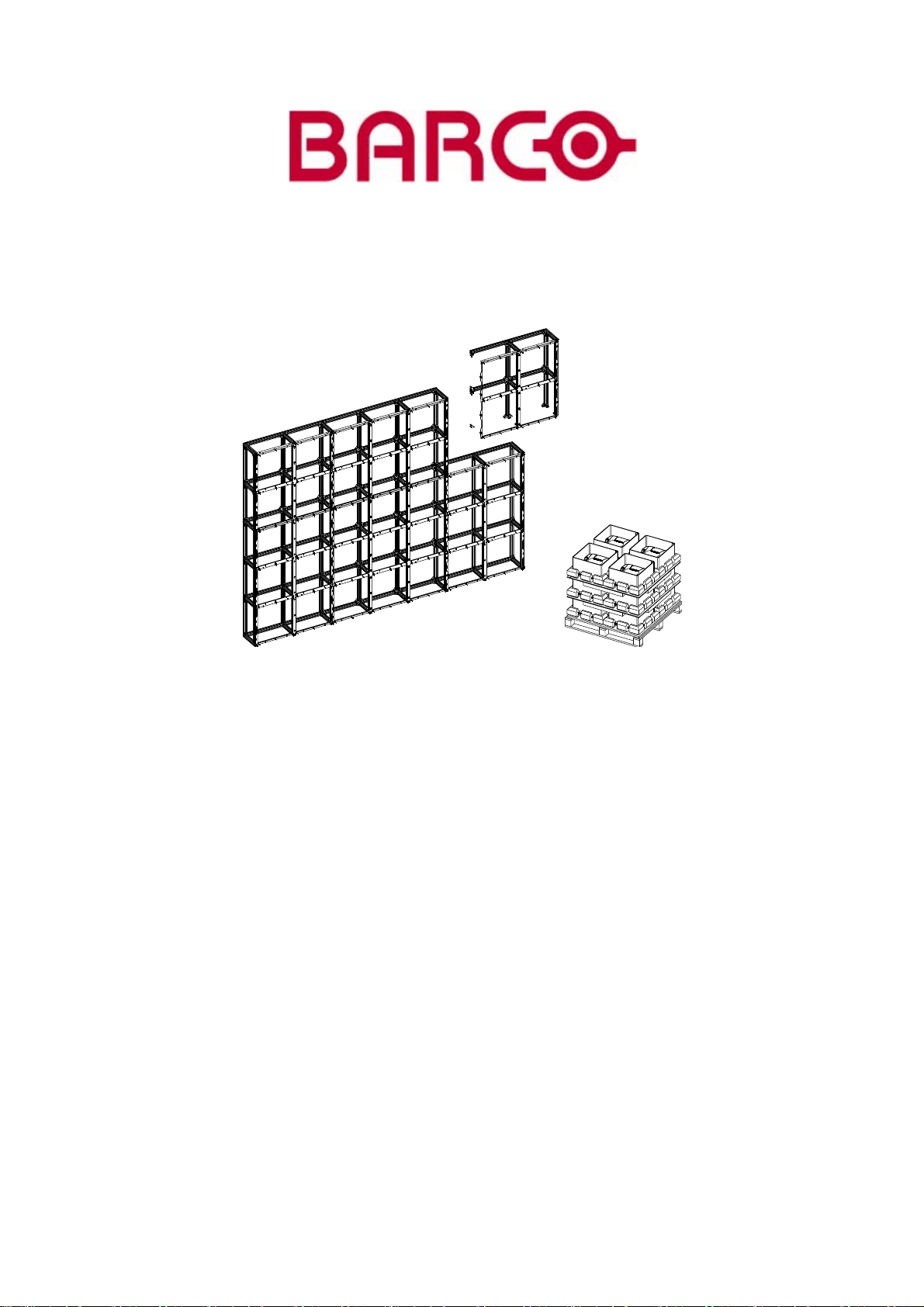
FIXED ILITE DISPLAY
INSTALLATION MANUAL
For I6, I6 XP, I8, I10 & I12 tiles
05042004 R5976522/02
Page 2

Barco nv Media
aan 5, B-8520 Kuurne
Noordl
Phone: +32 56.36.89.70
Fax: +32 56.36.88.24
E-mail:
Visit us at the web: www.barco.com
Printed in Belgium
Page 3

Copyright ©
All rights reserved. No part of this document may be copied, reproduced or translated. It shall not otherwise be recorded, transmitted or
stored in a retrieval system without the prior written consent of Barco.
Guarantee and Compensation
Barco provides a guarantee relating to perfect manufacturing as part of the legallystipulatedtermsofguarantee. On receipt, the purchaser
must immediately inspect all delivered goods for damage incurred during transport, as well as for material and manufacturing faults Barco
must be informed immediately in writing of any complaints.
The period of guarantee begins on the date of transfer of risks, in the case of special systems and software on the date of commissioning,
at latest 30 days after the transfer of risks. In the event of justified notice of compliant, Barco can repa ir the fault or provide a replacement
at its own discretion within an appropriate period. If this measure proves to be impossible or unsuccessf ul, the purchaser can demand a
reduction in the purcha se price or cancellation of the contract. All other claims, in particular those relating to compensation for direct or
indirectdamage,andalsodamage attributed to the operationofsoftw ar e as well as tootherservices provided by Barco, being acomponent
ofthesystemo r independent service, will bedeemedinvalidprovided the damage isnotp roven to be attributed totheabsence of properties
guaranteed in writing or due to the intent or gross negligence or part of Barco.
If the purchaser or a third party carries out modifications or repairs on goods delivered by Barco, or if the goods are handled incorrectly,
in particular if the systems are commissioned operated incorrectly or if, after the transfe
agreed upon in the contract, all guarantee claims of the purch aser will be rendered invalid. Not included in the guarantee coverage are
system failures which are attributed to programs or special electronic circuitry provided by the purchaser, e.g. interfaces. Normal wear as
well as normal maintenance are not subject to the guarantee provided by Barco either.
The environmental conditions as well as the servicing and maintenance regulations specified in the this manual must be complied with by
the customer.
r of risks, the goods are subject to influences not
Changes
Barco provides this manual ’as is’ without warranty of any kind, either expressed or implied, including but not limited to the implied warranties or merchantability and fitness for a particular purpose. Barc
program(s) described in this publication at any time without notice.
This publication could contain technical inaccuracies or typographical errors. Changes are periodically made to the information in this
publication; these changes are incorporated in new editions of this publication.
o may make improvements and/or changes to the prod uct(s) and/or the
Trademarks
Brand and product names mentioned in this manual may be trade
All brand and product names mentioned in this manual serve as comments o r examples and are not to be understood as advertising for
the products or their manufactures.
marks, registered trademarks or copyrights of their respective holders.
Federal Communications Commission (FCC Statement)
This equipment has been tested and found to comply with the limits for a class A digital device, pursuant to Part 15 of the FCC rules.
These limits are designed to provide reasonable protection against harmful interference when the equipment is operated in a commercial
environment. This equipment generates, uses, and can radiate radio frequency energy and, if not installed and used in accordance with
the instruction manual, may cause harmful interference to radio communications. Operation of this equipment in a residential area may
cause harmful interference, in which case the user will be responsible for correcting any interference.
Page 4

Page 5

Table of contents
TABLE OF CONTENTS
1. Safety.................................................................................................................. 3
1.1 Safetyguidelines...................................................................................................................... 3
1.2 Important safety instructions.......................................................................................................... 4
1.3 Important Warnings ................................................................................................................... 5
2. System Overview.................................................................................................... 7
2.1 Introduction............................................................................................................................ 7
2.2 Support structure...................................................................................................................... 8
2.3 Assemblyblocks for an ILite display system ......................................................................................... 8
2.3.1 ILite assembly blocks........................................................................................................... 8
2.3.2 Order info ILite assembly blocks ...............................................................................................9
2.4 ILite display tiles....................................................................................................................... 9
2.4.1 ILite displaytiles ................................................................................................................ 9
2.4.2 Order info ILite tiles............................................................................................................10
2.4.3 Technical summary ILite tiles.................................................................................................. 10
2.4.3.1 Specifications ILite 6 tile ................................................................................................10
2.4.3.2 Specifications ILite 6 XP tile ............................................................................................ 11
2.4.3.3 Specifications ILite 8 tile ................................................................................................12
2.4.3.4 Specifications ILite 10 tile...............................................................................................12
2.4.3.5 Specifications ILite 12 tile...............................................................................................13
2.4.4 ILite tile dimensions............................................................................................................14
2.5 Cablesfor ILite displays..............................................................................................................14
2.5.1 Power cables ..................................................................................................................14
2.5.2 Data cables ....................................................................................................................17
2.6 Powerboxes.......................................................................................................................... 18
2.7 Digitizer ...............................................................................................................................18
2.8 Fiberlink system...................................................................................................................... 18
2.9 Control software......................................................................................................................18
3. Physical installation ...............................................................................................19
3.1 Installation of the support structure.................................................................................................. 19
3.2 Preparation of the ILite assembly blocks............................................................................................ 19
3.2.1 Assembly blockpositioning code .............................................................................................19
3.2.2 Removing sidesfrom ILite assembly blocks.................................................................................. 20
3.2.2.1 Removingsides .........................................................................................................20
3.2.2.2 Removingthe left sidefrom an ILite assembly block..................................................................21
3.2.2.3 Removingthe bottom sidefrom an ILiteassembly block.............................................................. 21
3.3 Correct alignment of the ILite assembly blocks .....................................................................................22
3.4 Attachthe ILite assembly blocks .................................................................................................... 23
3.5 ILite tile mounting ....................................................................................................................26
3.6 Cabling of the ILite display...........................................................................................................28
3.6.1 ILite tile input/output ports ..................................................................................................... 28
3.6.2 Power cabling.................................................................................................................. 29
3.6.2.1 Connections with a Mono Phase Power Box ..........................................................................29
3.6.2.2 Connections with a Custom Power Box................................................................................31
3.6.3 Data cabling ...................................................................................................................32
4. Servicing .............................................................................................................35
4.1 Safetyinstructions.................................................................................................................... 35
4.2 ILite tile diagnostic ...................................................................................................................35
4.3 Tile accessing ........................................................................................................................ 36
4.4 Hot swap of an ILite tile..............................................................................................................37
Index......................................................................................................................39
R5976522 FIXED ILITE DISPLAY 05042004 1
Page 6

Table of contents
2 R5976522 FIXED ILITE DISPLAY 05042004
Page 7
1. SAFETY
1.1 S afety guidelines
Personal protection
1. Safety
Image 1-1
Warning
Be aware of suspende
loads.
Image 1-2
Suspended loads
d loads, wear a hard hat to reduce the risk of personal injury. Mind your fingers while working with heavy
Image 1-3
Hard hat
Image 1-4
Mind your fingers
Installation personnel
This installation must be performed by authorized and qualified technical personnel only.
Accredited safety officers must ensure the safety of the site, construction, assembly, connection, use, dismantling, transport etc. of
such safety cri
tical systems.
Caution
Installation shouldbeperformed onlyafteryo u are thoroughly familiarwithallof the proper safetychecksandinstallation instructions.
To do otherw ise increases the risk of hazards and injury to the user.
Assembly parts are designed for intended use only in conjunction with Barco LED walls.
Do not modify and/or replicate any component. Barcouses specific materials and manufacturing processes in order to achieve part
strength. Consult Barco for assistance with custom applications.
Always follow Barco installation instructions. Contact Barco if you should have any question regarding the safety of an application.
The manufacturer assumes no liability for incorrect, inadequate, irresponsible or unsafe assembly of systems.
Product care
Structural & mounting components should be kept dry, clean, lubricated (only if recommended), coated properly, and otherwise
maintaine
inspected on a routine basisforsecurity, wear,deformation, corrosionandanyothercircumstancesthat may affect the load handling
capability of the part.
Barco recommends inspections at regular intervals for all installations and increasing in frequency for more critical installations. If
a part is found to have damage, which m ay cause a decrease in load capability, the part must be removed for service or replaced
immediately.
Under no circumstances are Barco parts repairable by anyone other than Barco.
d in a manner consistent with part design. Barco products must be used in a manner c onsistent with their design and
R5976522 FIXED ILITE DISPLAY 05042004
3
Page 8

1. Safety
1.2 Important safety instructions
Instructions:
• Read these instructions.
• Keep these instructions.
• Heed all warnings.
• Follow all instructions.
• Clean only with materials or chemicals that are inert, nonabrasive, noncorrosive and non-ma rking. Consult the manufacturer
for further advice should any doubts exist reg arding any cleaning procedure.
• Do not block ventilation openings. Install in accordance with the manufacturers instructions.
• Do not install near any heat sources such as radiators, heat registers, stoves, or other apparatus (including amplifiers) that
produce heat.
• Do not de feat the safety purpose of the polarized or grounding type plugs/sockets. If the provided sockets/plugs are damaged
then replacement of the defe ctive parts must be undertaken immediately.
• Protect the power/data cords from being walked on or pinched particularly at plugs, convenience receptacles, and the point
where they exit from the apparatus. Replace damaged power/data cords immediately.
• Only use attachments/accessories specified by the manufacturer.
• Disconnect the power to this apparatus during lightning storms or provide suitable additional lightning protection. Unplug this
apparatus when unused for long period of time.
• Refer all servicing to qualified service technicians/personnel. Servicing is required when the apparatus has been damaged in
any way, such as power-supply cord or plug is damaged, the apparatus does not operate normally, or has been dropped.
• Useonlywithsystems or peripheralsspecifiedby the manufacturer,orsold with theapparatus. Use ca
or transporting to avoid damage by possible tipping.
ution duringlifting/moving
4
R5976522 FIXED ILITE DISPLAY 05042004
Page 9
1.3 Important Warnings
Important Warnings:
• Risk of electric shock:
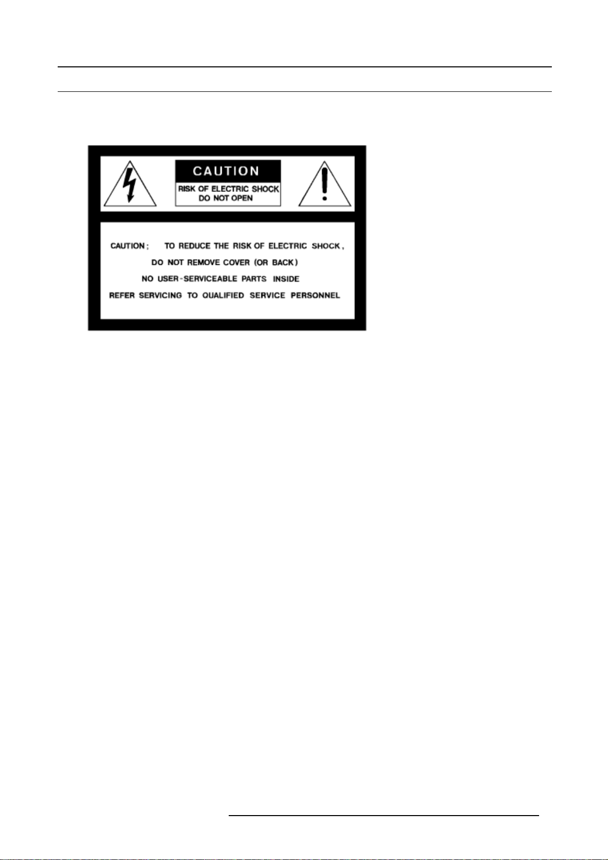
Image 1-5
Risk of electrical shock
Risk of electric shock. Do not open. To reduce the risk of electric shock, do not remove cover (or back). No user-serviceable
parts inside. Refer servicing to qualified service personnel.
The lightning flash with an arrowhead within a triangle is intende
of electrical shock to persons.
The exclamation point within a triangle is intended to tell the u ser that important operating and/or servicing instructions are
included in the technical documentation for this equipm
• Maximum ambient temperature:
The maximum ambient temperature for the LED wall is 40 °C, the minimum temperature is -10 °C.
• High leakage current:
The combination of multiple tiles in an installation results in increased levels of leakage current. In order to avoid risk of electric
shock due to high leakage current, proper grounding of the installation is required.
• Flammable materials:
Keep flammable materials away from the installation (such as curtains). A lot of e nergy is transferred into heat. Theinstallation
should be such that the amount of air flow required for safe operation of the equipment is not compromised. Proper ventilation
must be provided.
• ESD and LED’s:
LED components used in ILite devices are ESD (Electro-Static Discharge) sensitive. To prevent the possibility of destroying
LED components do not touch either in operation or whil
• Risk of electric shock / Risk of fire:
To protect against risk of fire by overloadin g of power cables, MAXIMUM 6 TILES in one column may be connected in parallel.
Each source cable supplying a column of MAXIM UM 6 TILES should be protected by a circuit breaker or fuses rated 16 A / 250
V.
• Disconnect device:
When the appliance inlets of the individual tiles a
the equipment and be easily accessible, or a readily accessible general disconnect device shall be incorporated in the fixed
wiring.
• This equipment MUST be earthed:
In order to protect against risk of electric shock, the insta llation should be properly grounded. Defeating the purpose of the
grounding type plug will expose you to the risk of electric shock.
• Power system:
It is recommended to use a TN-S power distribution system (a power distribution system with a separate neutral and grounding
conductor) in order to avoid large ground currents loops due to voltage differences in the neutral conductor. The total electrical
installation should be protected by an appro
rupters. The installation sh all be done according to the local electrical installation codes. In Europe special attention should be
given to EN 60364, the standard for electrical installation of buildings. In Germany VDE 0100 should be adhered to.
• Mains cords:
The power cords deliveredwiththissystemhavespecialproperties for safety. They are not user serviceable. If the power cords
are damaged, replace only with new ones. Never try to repair a power cord.
1. Safety
d to tell the user that parts inside this product may cause a risk
ent.
e switched off.
re not accessible, the socket outlets supplying the rack shall be installed near
priate rated disconnect switch, circuit breakers and Ground Fault Current Inter-
R5976522 FIXED ILITE DISPLAY 05042004
5
Page 10

1. Safety
6 R5976522 FIXED ILITE DISPLAY 05042004
Page 11
2. SYSTEM OVERVIEW
Overview
• Introduction
• Support structure
• Assembly blocks for an ILite display system
• ILite display tiles
• Cables for ILite displays
• Power boxes
• Digitizer
• Fiberlink system
• Control software
2.1 Introduction
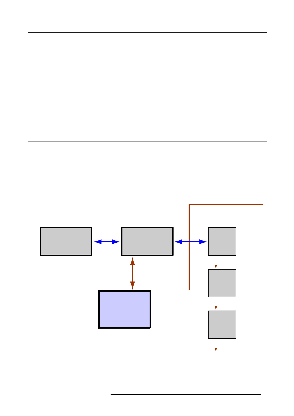
The fundamental elements of a ILite display system are:
• Support structure.
• Assembly blocks.
• ILite display tiles.
• Power box.
• Digitizer.
• Control software.
2. System Overview
Block diagram ILite display system
Sources Digitizer
RS232
Control
PC
ILite Display
Tile 1
Tile 2
Tile 3
Image 2-1
R5976522 FIXED ILITE DISPLAY 05042004 7
Page 12
2. System Overview
2.2 S upport structure
Support structures
Screen supporting/securing structures are not described in this manual, because the vary from system to system. Although, the
following must be taken into account and must be precisely calculated on individual basis:
1. Weight tolerances.
2. Ceiling heights (floor or suspended).
3. Ballast loads (for base stand assemblies).
4. Front or rear clearances.
5. Stacking limitations.
6. Environmental conditions.
7. Location.
8. Ground clearances.
9. Ground stability.
10. Local regulations regarding such installations.
Individual basis
Support structures must be assessed on an individual basis. Never construct a w all if there is uncertainty regarding the stability of
an installation o r the load holding capabilities. If there are doubts on a systems viability, consult Barco for advise on pro fessional
rigging organizations.
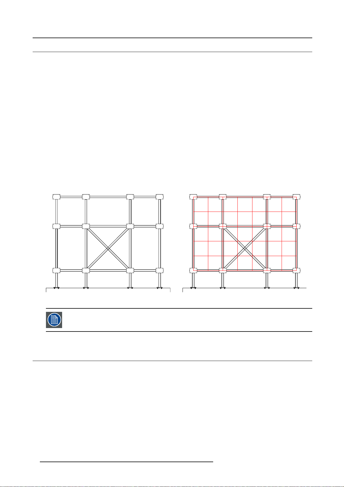
Example of a support structure
Image 2-2
ILitesupportstructureforaH7xV5ILitedisplay.
The support structure in the above example is pure illustra
support structures are possible for the same size of an ILite display. Contact Barco NV.for more information.
tive for a H7 x V5 ILite display. Several variants of
2.3 A ssembly blocks for an ILite display system
2.3.1 ILite assembly blocks
Introduction
The assembly of a system due to the multitude of possible screen sizes / configurations is difficult to assume. Eight different sizes
of assembly blocks (basic building frames) are available having tile arrangements in the ratios H2 x V2, H2 x V3, H2 x V 4, H3 x V2,
H3xV3,H3xV4,H4xV2,H4xV3(H = Horizontal space for ILite tile & V = Vertical space for ILite tile). This modular concept
gives rise to configurations of unlimited possibility, screen dimensions of the most desirable s izes can be rapidly constructed, with
maximum flexibility.
The assembly blocks are prepared on the ground and then raise to their desired position, depending on the circumstances and
facilities available.
ILite assembly blocks are only to be used in conjunction with BARCO ILite modules.
8
R5976522 FIXED ILITE DISPLAY 05042004
Page 13
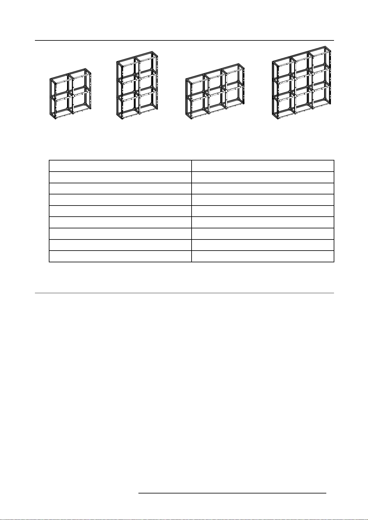
Image 2-3
ILite assembly blocks.
2.3.2 Order info ILite assembly blocks
Order info:
Article No. Description
R9850780 ILite assembly block H2 x V2
R9850781 ILite assembly block H2 x V3
R9851630 ILite assembly block H2 x V4
R9850782 ILite assembly block H3 x V2
2. System Overview
R9850783 ILite assembly block H3 x V3
R9850784 ILite assembly block H3 x V4
R9851640 ILite assembly block H4 x V2
R9850785 ILite assembly block H4 x V3
2.4 ILite display tiles
2.4.1 ILite display tiles
Introduction
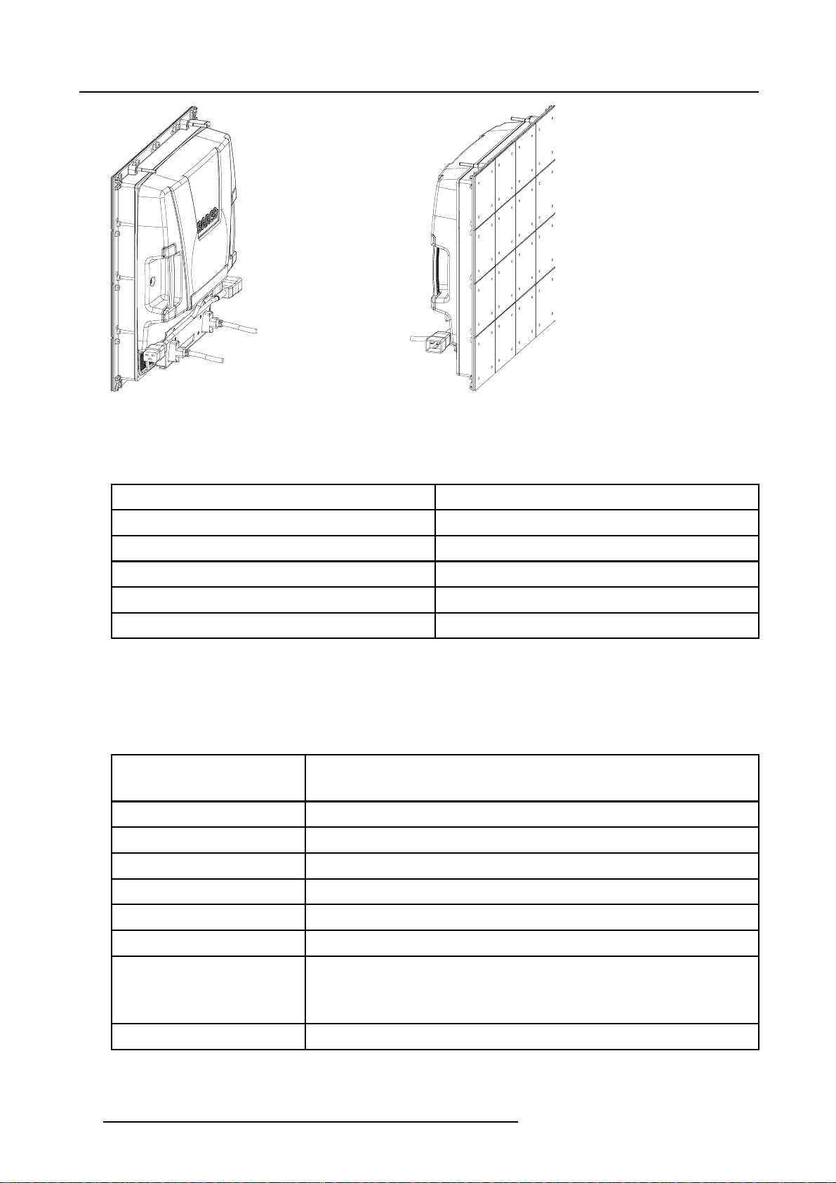
The ILite range is del
effect, alignment problems and low contrast level. But offering shallow depth, long lifetime, increased ruggedness and incredible
picture dynamics. Built-in intelligence provides for auto-calibration of the full display, hot swap of tiles and diagn ostic capabilities.
An embedded PC e
of a great deal of the added value offered by the ILite. An extreme fill factor and high resolution offers a full color blended picture a t
distances smaller than 3 meters. Half of the full brightness is still perceived at angles of 145º from the s urface of the display.
ivering a quality picture of a video cube without its inherent technology limits as hotspot-effect, jailhouse-
quips every ILite tile, providing it with intelligence and advanced logic handling capabilities. This PC is the host
R5976522 FIXED ILITE DISPLAY 05042004
9
Page 14
2. System Overview
Image 2-4
ILite tile.
2.4.2 Order info ILite tiles
Order info:
Article No. Description
R9004040 ILite 6 tile
R9010250 ILite 6 XP tile
R9004060 ILite 8 tile
R9004050 ILite10tile
R9004111 ILite12tile
2.4.3 Technical summary ILite tiles
2.4.3.1 Specifications ILite 6 tile
Specifications
Contrast R atio 950:1(500lux)
1.625 : 1 (225 lux)
Screen size
Weight 13 kg
Hor. viewing angle
Vert. viewing angle
Unlimited
> 145°
> 145°
Avg Power Consumption 100 W / tile
Max Power Consumption 400 W / tile
Tile dimensions Width: 0,448 m
Height: 0,448 m
Depth: 0,1495 m
Visual Resolution 6mm
10 R5976522 FIXED ILITE DISPLAY 05042004
Page 15

Temperature range operating:
0°C <> 40°C
storage:
-20°C <> 60°C
Brightness 2.500 NIT
2. System Overview
Calibrated Brigh tness
Lifetime 45.000h [half brightness]
Processing +10bit
Source compatibility S-Video - Composite - YUV - R GB - SD I - HDSD I - Data DVI up to UXGA
2.000+ NIT
2.4.3.2 Specifications ILite 6 XP tile
Specifications
Pixel pitch 6mm
Brightness 2500 NIT
Calibrated Brigh tness 2000 NIT (calibrated at 6500°K)
LED conf iguration 3-in-1 SMD
Pixel density
Hor. viewing angle
Vert. viewing angle
Contrast R atio
25.920/m² (2410/ft²)
5.184/tile (72x72)
145° + (min. 50% brightness)
145° + (min. 50% brightness)
950:1
Lifetime 45000h (full white - half brightness)
Power consumption
Colors
Weight
Processing
Refresh rate 400 Hz (PAL/NTSC minimum)
Temperature range operating:
Humidity operating:
Certifications UL-CE-TUVClassA
maximum: 400W / tile
average: 100W / tile
4,4 trillion
13 Kg (28,7 lbs)
14bit/color (Color)
8bit/color (Greyscale)
0-40°C(32-104°F)
storage:
-20 - 60°C (-4 - 140°F)
35 - 85%
storage:
10 - 90%
R5976522 FIXED ILITE DISPLAY 05042004 11
Page 16
2. System Overview
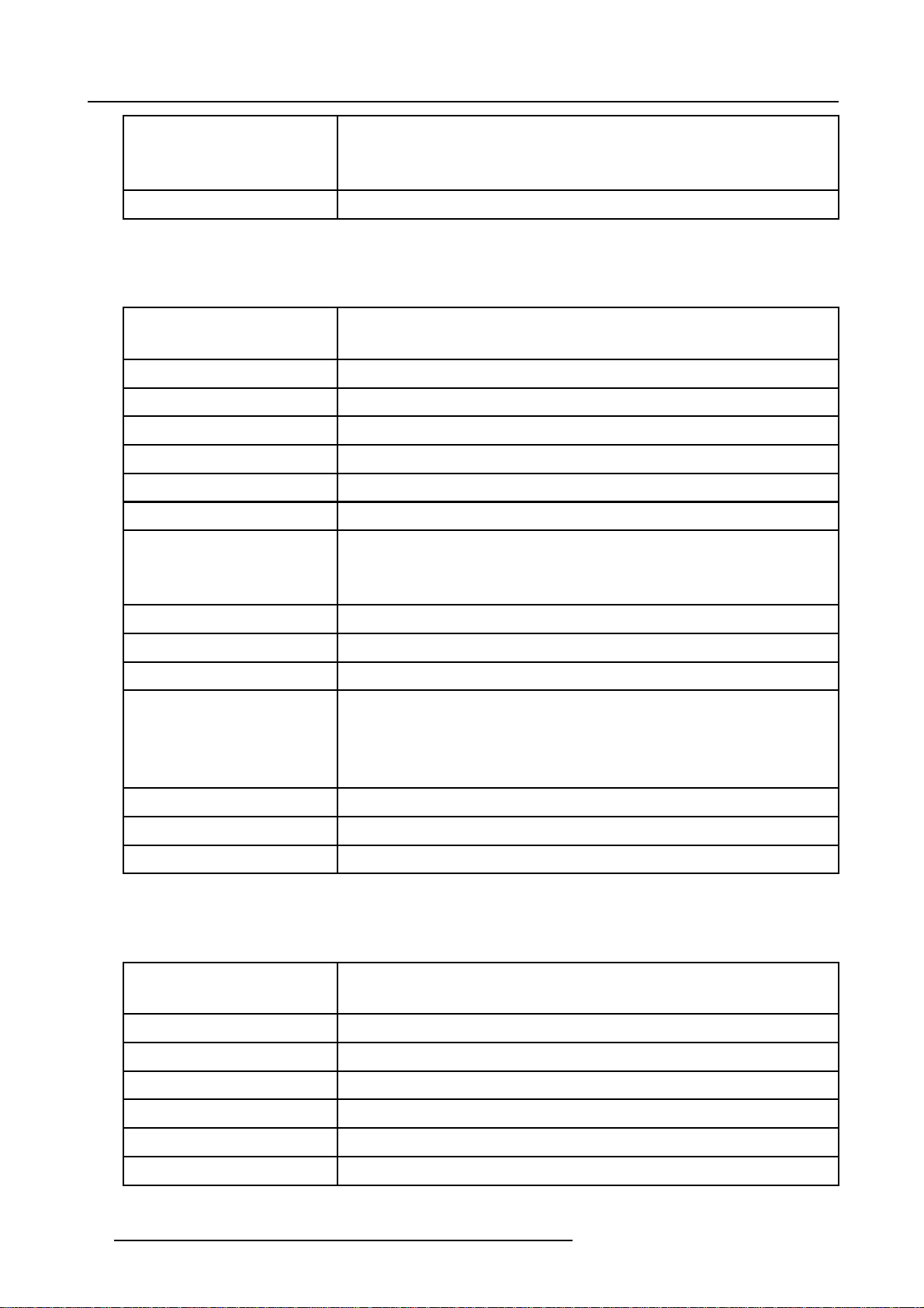
Tile dimensions
Source compatibility S-Video / Composite / YUV / RG B / SDI / HD SDI / Data DVI up to SXGA
Width: 448mm (17.7")
Height: 448mm (17.7")
Depth: 149,5mm (5.89")
2.4.3.3 Specifications ILite 8 tile
Specifications
Contrast R atio 950:1(500lux)
1625 : 1 (225 lux)
Screen size
Weight 13 kg
Hor. viewing angle
Vert. viewing angle
Avg Power Consumption 100 W / tile
Max Power Consumption 400 W / tile
Tile dimensions Width: 0,448 m
Unlimited
> 145°
> 145°
Height: 0,448 m
Depth: 0,1495 m
Visual Resolution 8mm
Brightness 2.500 NIT
Calibrated Brigh tness
Temperature range operating:
Lifetime 45.000h [half brightness]
Processing +10bit
Source compatibility S-Video - Composite - YUV - R GB - SD I - HDSD I - Data DVI up to UXGA
2.000+ NIT
0°C <> 40°C
storage:
-20°C <> 60°C
2.4.3.4 Specifications ILite 10 tile
Specifications
Contrast R atio 950:1(500lux)
1.625 : 1 (225 lux)
Screen size
Weight 13 kg
Unlimited
Hor. viewing angle
Vert. viewing angle
Avg Power Consumption 100 W / tile
Max Power Consumption 400 W / tile
12 R5976522 FIXED ILITE DISPLAY 05042004
> 145°
> 145°
Page 17
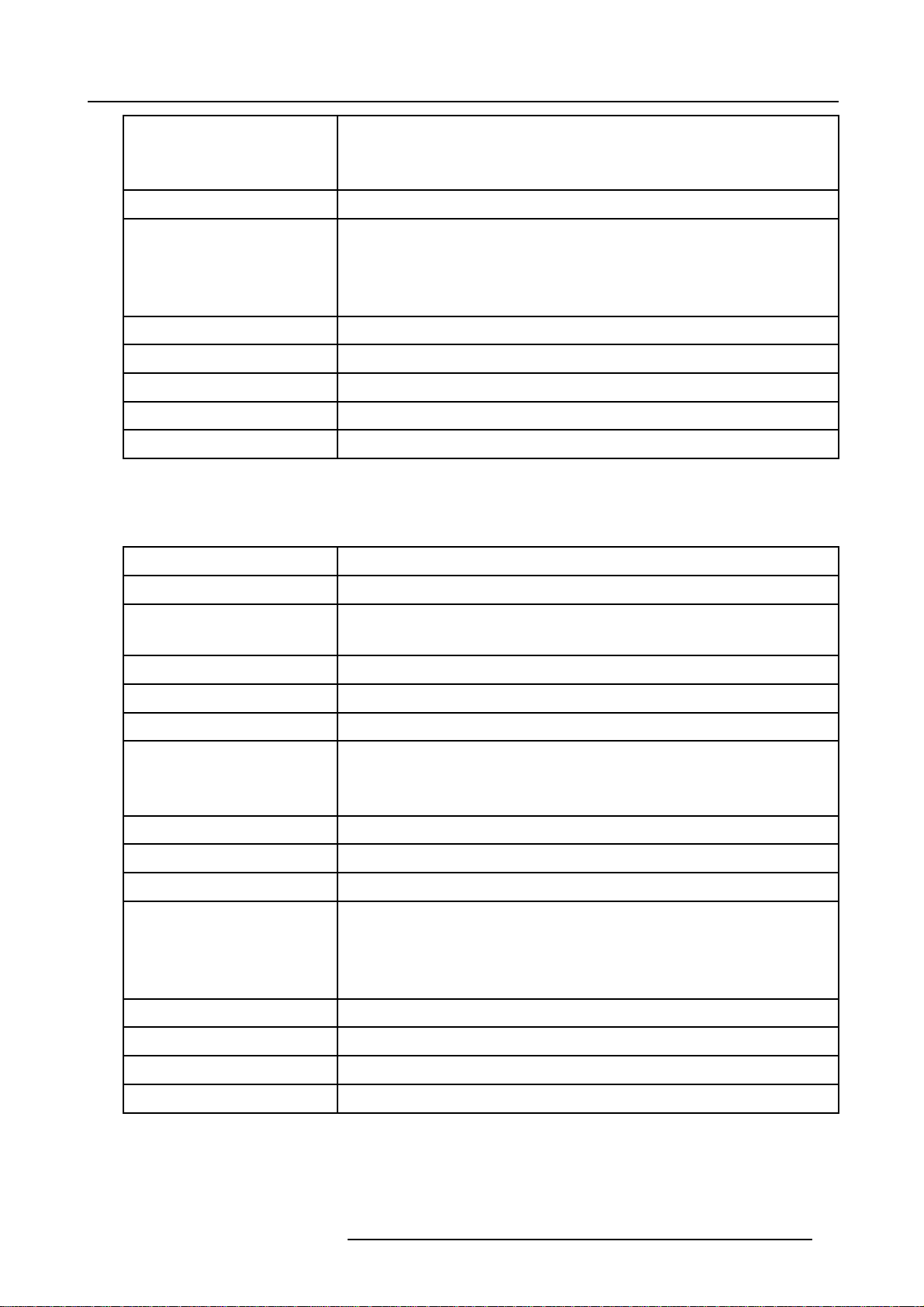
Tile dimensions Width: 0,448 m
Height: 0,448 m
Depth: 0,1495 m
Visual Resolution 10 mm
Temperature range operating:
0°C <> 40°C
storage:
-20°C <> 60°C
Brightness 2.500 NIT
2. System Overview
Calibrated Brigh tness
Lifetime 45.000h [half brightness]
Processing +10bit
Source compatibility S-Video - Composite - YUV - R GB - SD I - HDSD I - Data DVI up to UXGA
2.000+ NIT
2.4.3.5 Specifications ILite 12 tile
Specifications
Brightness 2.500 NIT
Calibrated Brigh tness
Contrast R atio 950:1(500lux)
Visual Resolution 12 mm
Hor. viewing angle
Vert. viewing angle
Tile dimensions Width: 0,448 m
2.000+ NIT
1.625 : 1 (225 lux)
> 145°
> 145°
Height: 0,448 m
Depth: 0,1495 m
Weight 13 kg
Avg Power Consumption 100 W / tile
Max Power Consumption 400 W / tile
Temperature range operating:
0°C <> 40°C
storage:
-20°C <> 60°C
Screen size
Lifetime 45.000h [half brightness]
Processing +13bit
Source compatibility S-Video - Composite - YUV - R GB - SD I - HDSD I - Data DVI up to UXGA
R5976522 FIXED ILITE DISPLAY 05042004 13
Unlimited
Page 18

2. System Overview
2.4.4 ILite tile dimensions
Dimensions:
448
101,9
8
4
4
25
430,5
286
M6 max 15mm deep
132 116
Image 2-5
Dimensions given in millimeters.
2.5 Cables for ILite displays
2.5.1 Power cables
General
Depending on the size and configuration of the ILite display several sizes and types of power cables are needed. The picture below
(image 2-6) illustrates the available power c
Image 2-6
Power connector types:
ATypeCEEmale.
BTypeC13female.
CTypeC19female.
DTypeC20male.
onnector types for an ILite Display.
Image 2-7
Detail male multi pole connector.
Used on theCustom Power Box, multi
power cable and Spider connector.
14 R5976522 FIXED ILITE DISPLAY 05042004
Page 19

2. System Overview
The power cords delivered with the ILite display system have special properties for safety. They are not user
serviceable. If the power cords are damaged, replace only with new ones. Never try to repair a power cord.
Order info:
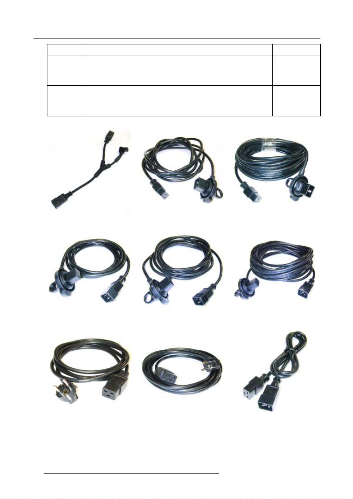
Article No. Description Image
R9851130
R9851131
R9851132
R9851140
R9851150
R9851136
R9851141
R9851151
R9851160
One ILite power linking cable (C20 / C19 / C13).
Used to distribute power between tiles. Maximum 6 tiles per branch.
Package with 5 ILite power linking cables (C20 / C19 / C13).
Used to distribute power between tiles. Maximum 6 tiles per branch.
Package with 10 ILite power linking cables (C20 / C19 / C13).
Used to distribute power between tiles. Maximum 6 tiles per branch.
ILite power source cable (C20 waterproof / C19) 4,5 meter.
Used to distribute power from the Fiberlink Receiver to an ILite tile.
ILite power source cable (C20 waterproof / C19) 9 meter.
Used to distribute power from the Fiberlink Receiver to an ILite tile.
ILite power source cable (C20 / C19 waterproof) 2,5 meter.
Used to distribute power from an ILite tile to the Fiberlin k Receiver.
ILite power source cable (C20 / C19 waterproof) 4,5 meter.
Used to distribute power from an ILite tile to the Fiberlin k Receiver.
ILite power source cable (C20 / C19 waterproof) 9 meter.
Used to distribute power from an ILite tile to the Fiberlink Receiver.
ILite power source cable (CEE / C19) 2,5 meter.
Use to distribute power directly from the wall outlet to maximum 6 ILite tiles.
image 2-8
image 2-8
image 2-8
image 2-9
image 2-10
image 2-11
image 2-12
image 2-13
image 2-14
R9851170
R9851180
R9851190
R9851200
R9851260
R9851261
R9851262
R9851263
R9851264 Multi power cable with custom length.
R9851670
ILite power source cable (CEE / C19) 4 meter.
Used to distribute power directly from the wall outlet to maximum 6 ILite tiles.
ILite power extension lead (C2 0 / C19) 1,5 meter.
ILite power extension lead (C2 0 / C19) 2,5 meter.
ILite power extension lead (C20 / C19) 4 meter.
Multi power cable of 10 meter.
Used to distribute power between Custom Power Box and Spider connector.
Multi power cable of 20 meter.
Used to distribute power between Custom Power Box and Spider connector.
Multi power cable of 30 meter.
Used to distribute power between Custom Power Box and Spider connector.
Multi power cable of 50 meter.
Used to distribute power between Custom Power Box and Spider connector.
Used to distribute power between Custom Power Box and Spider connector.
ILite Spider connector with 6 power outputs (C19) with different lengths. Spid
bracket included.
Used to distribute power from a multi pow er cable to the ILite tiles. Maximum six
ILite tiles per Spider output cable.
image 2-15
image 2-16
image 2-17
image 2-18
image 2-19
er support
R5976522 FIXED ILITE DISPLAY 05042004 15
Page 20
2. System Overview
Article No. Description Image
R9851671
ILite Spider connector with 6 pow er outputs (C19) with same lengths. Spider support
bracket included.
Used to distribute power from a multi pow er cable to the ILite tiles. Maximum six
ILite tiles per Spider output cable.
R9851672
ILite Spider connector with 6 power outputs (C19) with custom lengths. Spider support
bracket included.
Used to distribute power from a multi pow er cable to the ILite tiles. Maximum six
ILite tiles per Spider output cable.
Image 2-8 Image 2-9 Image 2-10
Image 2-11 Image 2-12 Image 2-13
Image 2-14 Image 2-15 Image 2-16
16 R5976522 FIXED ILITE DISPLAY 05042004
Page 21
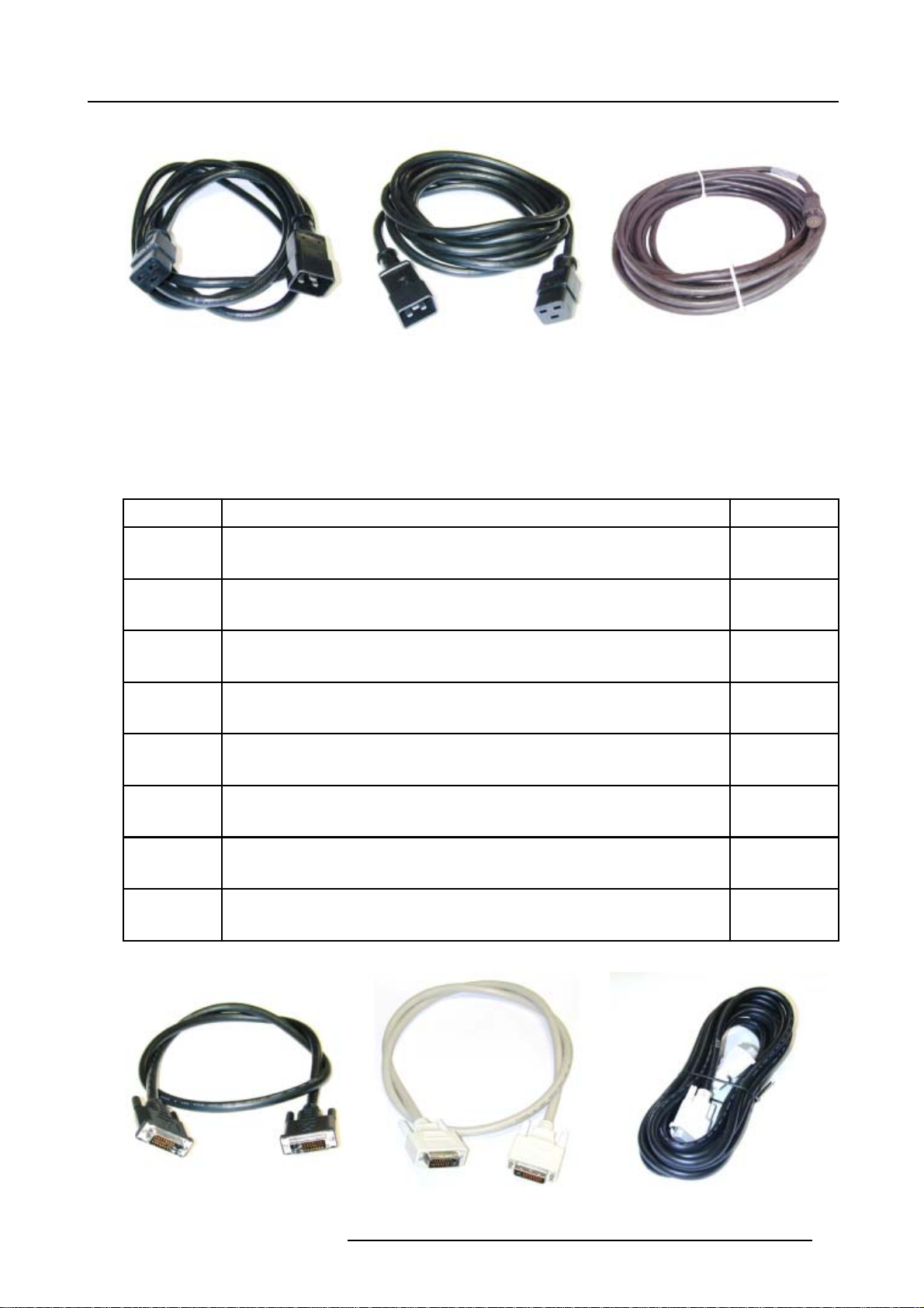
Image 2-17 Image 2-18 Image 2-19
2.5.2 Data cables
General
Depending on the size and configuration of the ILite display several sizes and types of data cables are needed.
Order info:
Article No. Description Image
2. System Overview
R9851211
R9851213
R9851214
R9851680
R9851210
R9851217
R9851218
R9851219
DVI-DVI data cable of 0,9 meter (screw type plugs).
Used to link data fro
Package with 5 DVI-DVI data cables of 0,9 meter (screw type plugs).
Used to link data from ILite tile to ILite tile.
Package with 10 DVI-DVI data cables of 0,9 meter (screw type plugs).
Used to link data from I
Package with 10 white DVI-DVI data cables of 0,9 meter (screw type plugs).
Used to link data from ILite tile to ILite tile.
DVI-DVI data cable of 5 meter (screw type plugs).
Used to link data from D3
MDR (wa terp roof) -DVI data cable of 5 meter.
Used to link data from Fiberlink Receiver to ILite tile.
DVI-MDR data cable of 5 meter.
Used to link data from D32
DVI-MDR data cable of 1 meter.
Used to link data from D320 Digitizer to Fiberlink Transmitter.
m I Lite tile to ILite tile.
Lite tile to ILite tile.
20 Digitizer to ILite tile.
0 Digitizer to F iberlink Transmitter.
image 2-20
image 2-21
image 2-22
image 2-23
image 2-24
image 2-25
Image 2-20 Image 2-21 Image 2-22
R5976522 FIXED ILITE DISPLAY 05042004 17
Page 22
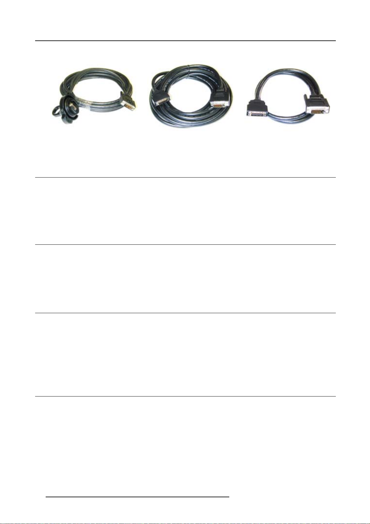
2. System Overview
Image 2-23 Image 2-24 Image 2-25
2.6 Power boxes
General
Depending on the size of the ILite display system, the power system has to be adapted. Therefore several sizes of power boxes are
available. For small and medium size ILite display systems the “Mono Phase Power Box” is used. For larger ILite display systems
there is a range of “Custom Power Boxes”. There is also a “Rental Power Box” available. Refer to the manual of the power box
used in the application for more information.
2.7 Digitizer
General
itizer processes (image processing, conversion and conditioning) all source signals for digital distribution to every tile. The
The dig
digitizer may be accessed directly or via the control software (e.g. XLite Toolset). This software is designed as a user interface
to be used in conjunction with the digitizer and display, this can be used when connected to the digitizer through a serial RS232
nnection. Refer to the manual of the digitizer for more information about the digitizer.
co
2.8 F iberlink system
General
The data signal coming out of the digitizer is transported from the digitizer to the display by a high-speed data link. To send such
a high density stream of data over long distances, a fiber optic cable is required. Barco offers a complete system: a transmitter, a
cable and a receiver.
Barco offers two different fiberlink systems: one for shorter distances, based on a multi mode optical fiber, and one for longer distances, based on a single mode optical fiber. Refer to the m anual of the fiberlink system for more information about the fiberlink
system.
2.9 Control software
General
The control software is designed as a graphic user interface (GUI) and can be used to control and configure the digitizer as well as
the Barco LED wall via a PC (e.g. XLite Toolset). Refer to the manual of the control software for more information about the control
software.
18
R5976522 FIXED ILITE DISPLAY 05042004
Page 23
3. PHYSICAL INSTALLATION
Overview
• Installation of the support structure
• Preparation of the ILite assembly blocks
• Correct alignment of the ILite assembly blocks
• Attach the ILite assembly blocks
• ILite tile mounting
• Cabling of the ILite display
3.1 Installation of the support structure
Follow the important Safety Guidelines.
What has to be done?
Dependent on the circumstances and facilities available:
3. Physical installation
• The complete support structure is assembled and installed on its final position before the assembly blocks and tiles are at-
tached.
• Thecomplete support structure is assembled on the floor first, and after the assembly blocks and tiles are attached, raised as
one structure to its vertical position and installed.
3.2 P reparation of the ILite assembly blocks
3.2.1 Assembly block positioning code
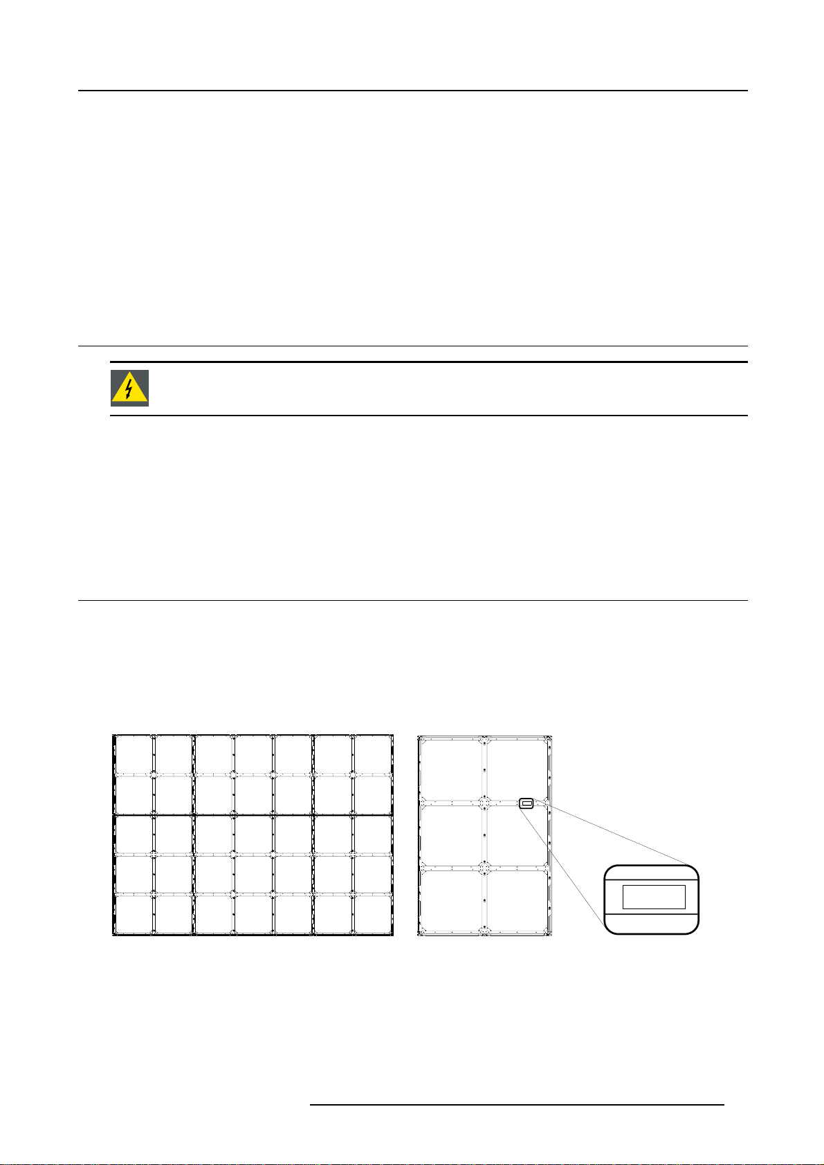
Understanding the position code
Each assembly block is coded with a letter followed by two numbers. The letter indicates the ILite display to which this assembly
block is part of (very useful incase there is more then one ILite display to install at the same location). The first number indicates the
row in wh ich to assemble, the second indicates the column. This code starts counting from the assembly in the bottom left corner.
A.2.1 A.2.2 A.2.3
A.1.1
A.1.1 A.1.2 A.1.3
A.1.1
Image 3-1
ILite display H7 x V5 assembly block codes.
R5976522 FIXED ILITE DISPLAY 05042004 19
Image 3-2
Location of positioningcode on an ILite assembly block.
Page 24
3. Physical installation
3.2.2 Removing sides from ILite assembly blocks
3.2.2.1 Removing sides
Why removing sides?
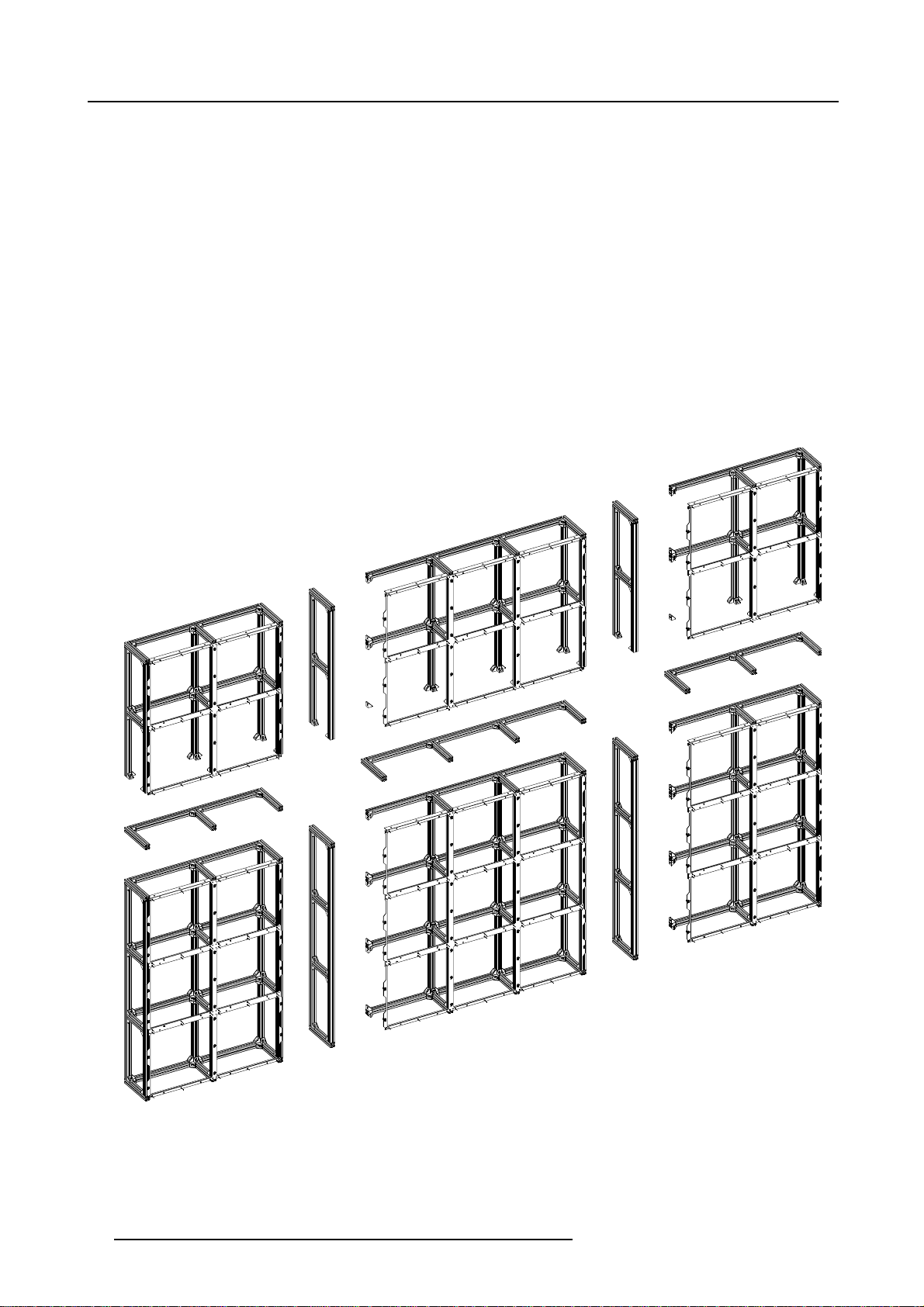
For transport reasons a ll the assembly blocks are delivered with all the sides attached. To join two assembly blocks together one of
the two sides at the adjoining edge, has to be removed.
Which sides to remove?
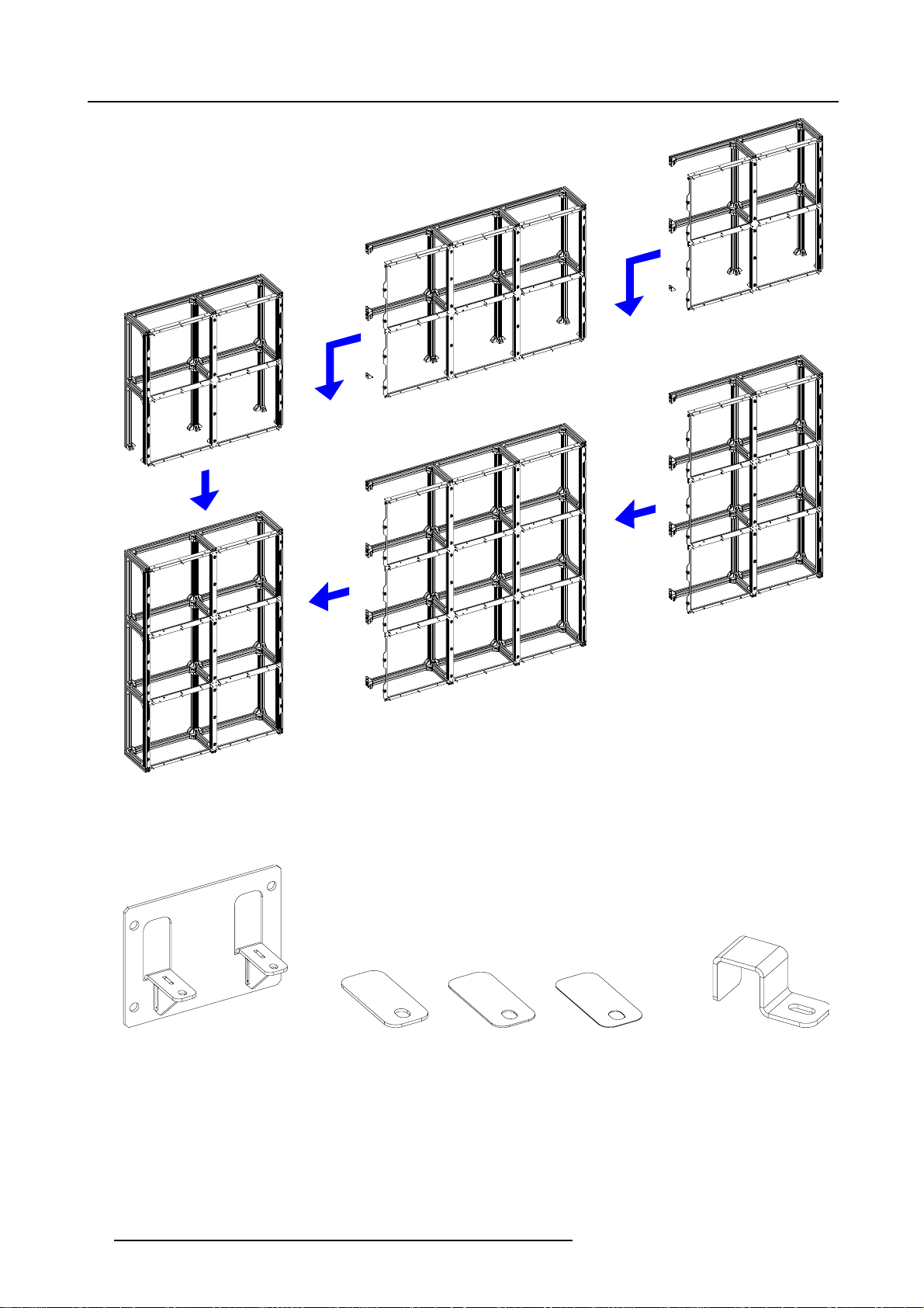
Either none, one or two sides of each assembly block will have to be removed, dependent on its location in the complete wall
assembly. If sides need to be detached, these are either the left or bottom side, or both left side & bo ttom, but never top or ri
because the ILite display wall is always build from left to right and bottom to top.
ght
• No sides need to be detached from de first assembly block (code d: x.1.1) which is located in the lower left corner of the IL
display.
• From the assembly blocks located in the first row (bottom row) of the I Lite display only the left side need to be detached.
• From the assembly blocks located in the first colum n of the ILite display only the bottom side need to be
• From all other assembly blocks in the ILite display as well the left side as the bottom side need to be detached.
detached.
ite
Image 3-3
Removed sides for an ILite display H7 x V5.
20 R5976522 FIXED ILITE DISPLAY 05042004
Page 25
3.2.2.2 Removing the left side from an ILite assembly block
Necessary tools
• Allen key 4 mm.
• Side cutter.
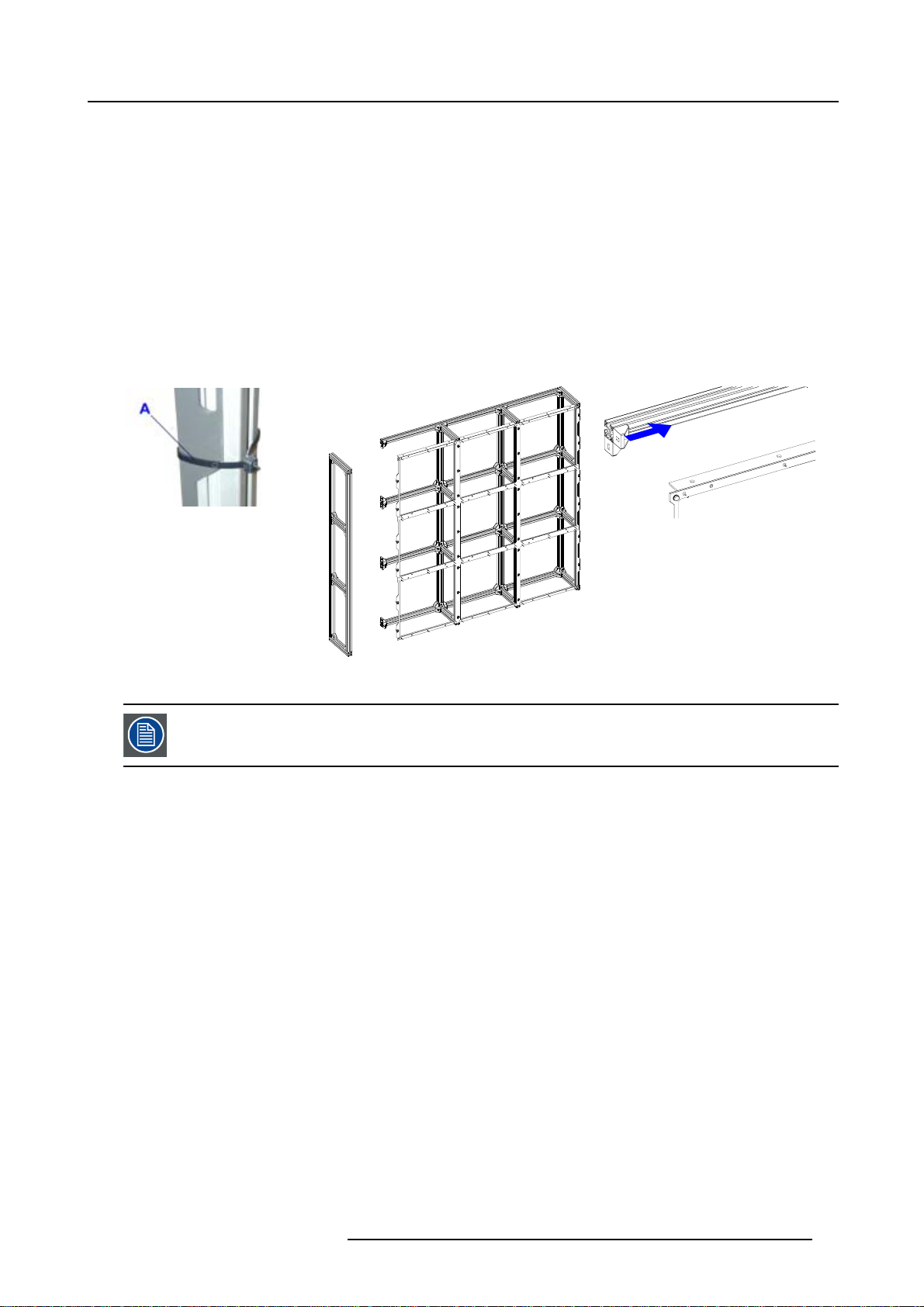
How to remove the left side ?
1. Undo and remove only the hexagon bolts in the aluminium corner brackets that secure the left side of the frame.
2. Remove, if present, the carrier straps around the left side of the ILite assembly block. (image 3-4)
3. Remove the left side from the assembly block. (image 3-5)
4. Is the final destination of this assembly block situated in the first row or column of the ILite display?
If yes, If yes, do not shift th e aluminium corner brackets.
If no, shift all aluminium corner brackets on th e left side o f the assembly block about three centimeters to the right by loosen the
hexagon bolts. (image 3-6)
3. Physical installation
Image 3-4
A Carrier strap to remove.
The 3 cm shift is necessary because otherwise it is impossible to place the assembly block against both other
joining assembl
replaced to their original position.
Image 3-5
Left side removed.
ies. Afte r placement of this assembly block in its final position in th e wall the corners are
Image 3-6
Three centimeters shift of the aluminium corner
brackets.
3.2.2.3 Removing the bottom side from an ILite assembly block
Necessary tools
• Allen key 4 mm.
• Side cutter.
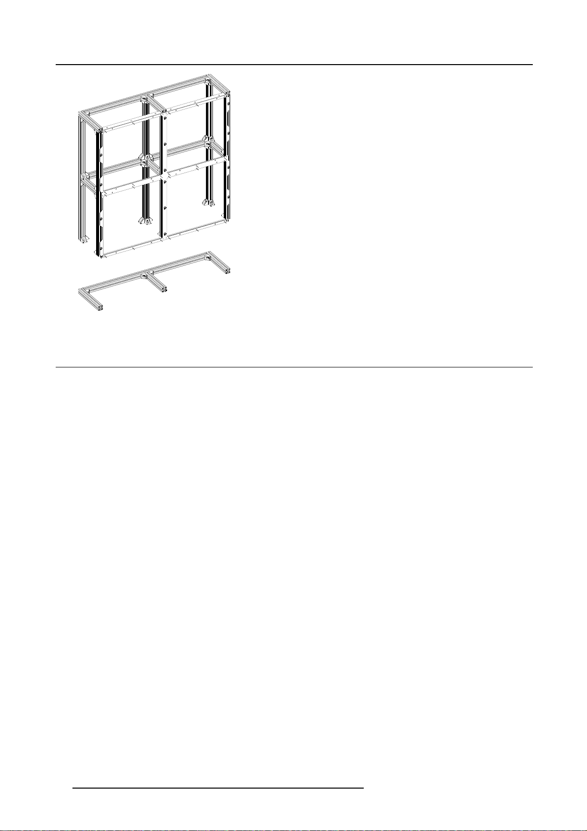
Procedure
1. Undo and remove only the hexagon bolts in the aluminium corner brackets that secure the bottom side of the frame.
2. Remove the bottom side from the assembly block. (image 3-7)
R5976522 FIXED ILITE DISPLAY 05042004
21
Page 26
3. Physical installation
Image 3-7
3.3 C orrect alignment of the ILite assembly blocks
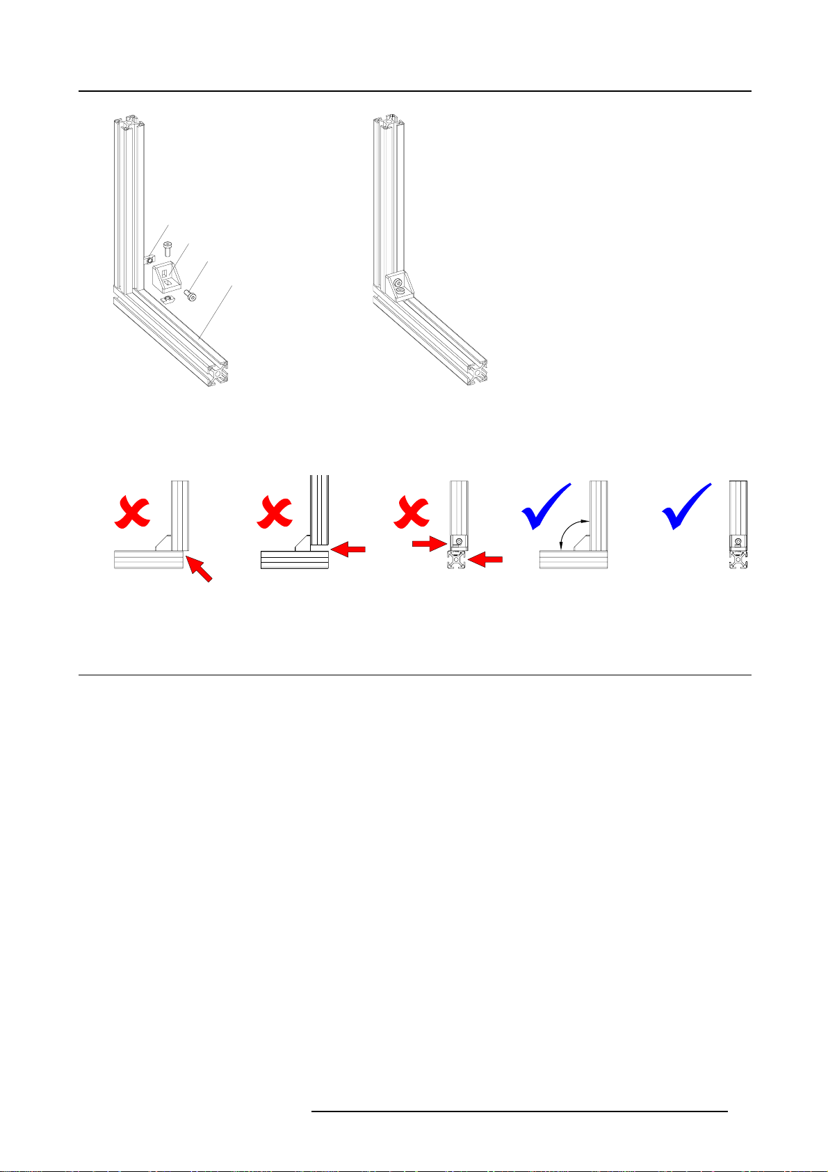
How to align assembly blocks correctly ?
For correct alignment of the assembly blocks is it important that the basic connection joint between the assembly blocks is properly
done. Such a basic connection joint consists of two aluminium profiles, one aluminium corner, two hexagon bolts and two nuts.
Necessary tools
Allen key 4 mm.
Making a basic connection joint
1. Ensure both nuts are in the correct position. 90 degrees turned compared to the aluminium profiles. (image 3-8)
2. Ensure no gap between the two profiles.(image 3-9)
3. Check if the sides of both profiles are in the same plane.(image 3-9)
4. Ensure the angle between the profiles is 90 degrees. (image 3-9)
22
R5976522 FIXED ILITE DISPLAY 05042004
Page 27
A
B
C
D
Image 3-8
ANut.
B ILite aluminium corner bracket.
C Hexagon bolt.
D Aluminium profile.
3. Physical installation
90º
Image 3-9
Making a basic connection joint between two profiles.
3.4 A ttach the ILite assembly blocks
What has to be done ?
The assembly blocks of the wall have to be attached to the support structure in succession and interconnected with one another.
Starting in the lower left corner of the ILite display, with the first assembly block (coded x.1.1), from left to right and from bottom
row to top row. For connections of the assembly blocks, ensure only the recommended variants are used, to comply with safety
guidelines. It’s important that every assembly block is assembled in the right location and configuration.
R5976522 FIXED ILITE DISPLAY 05042004
23
Page 28
3. Physical installation
A.2.1
A.2.3
A.2.2
5
4
3
1
A.1.2
A.1.1
Image 3-10
Example of assemble sequence for an ILite display H7xV5.
ILite fixation clamp
Per attachment point an ILite fixation clamp is required (article no. for 2 pieces : R9851450).
A
2
A.1.3
E
Image 3-11
ILite fixation clamp:
A Mounting plate.
B 2 mm shim plate.
C 1 mm shim plate.
D 0,5 mm shim plate.
E Support bracket.
24
BC D
R5976522 FIXED ILITE DISPLAY 05042004
Page 29
3. Physical installation
C
There are other attachment possibilities then described in this chapter. Contact Barco NV for more information.
Necessary tools
• Allen key 4 mm.
• Wrench17mm.
• Wrench13mm.
• Laser level.
Necessary parts
• Support structure.
• ILite assembly blocks.
• Mounting plates.
• Support brackets.
•Shimplates.
Procedure
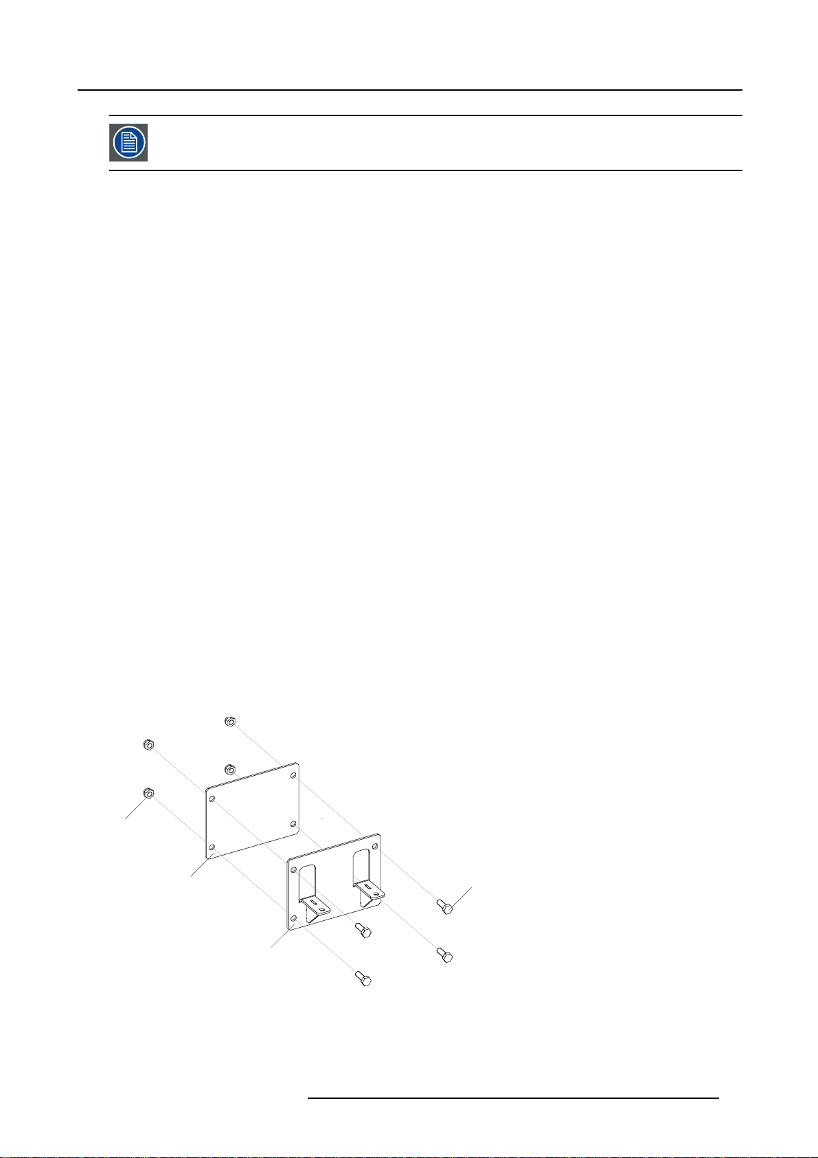
1. Attach a mounting plate on every mounting point of the support structure. Do this using four M10 bolts and nuts. (image 3-12)
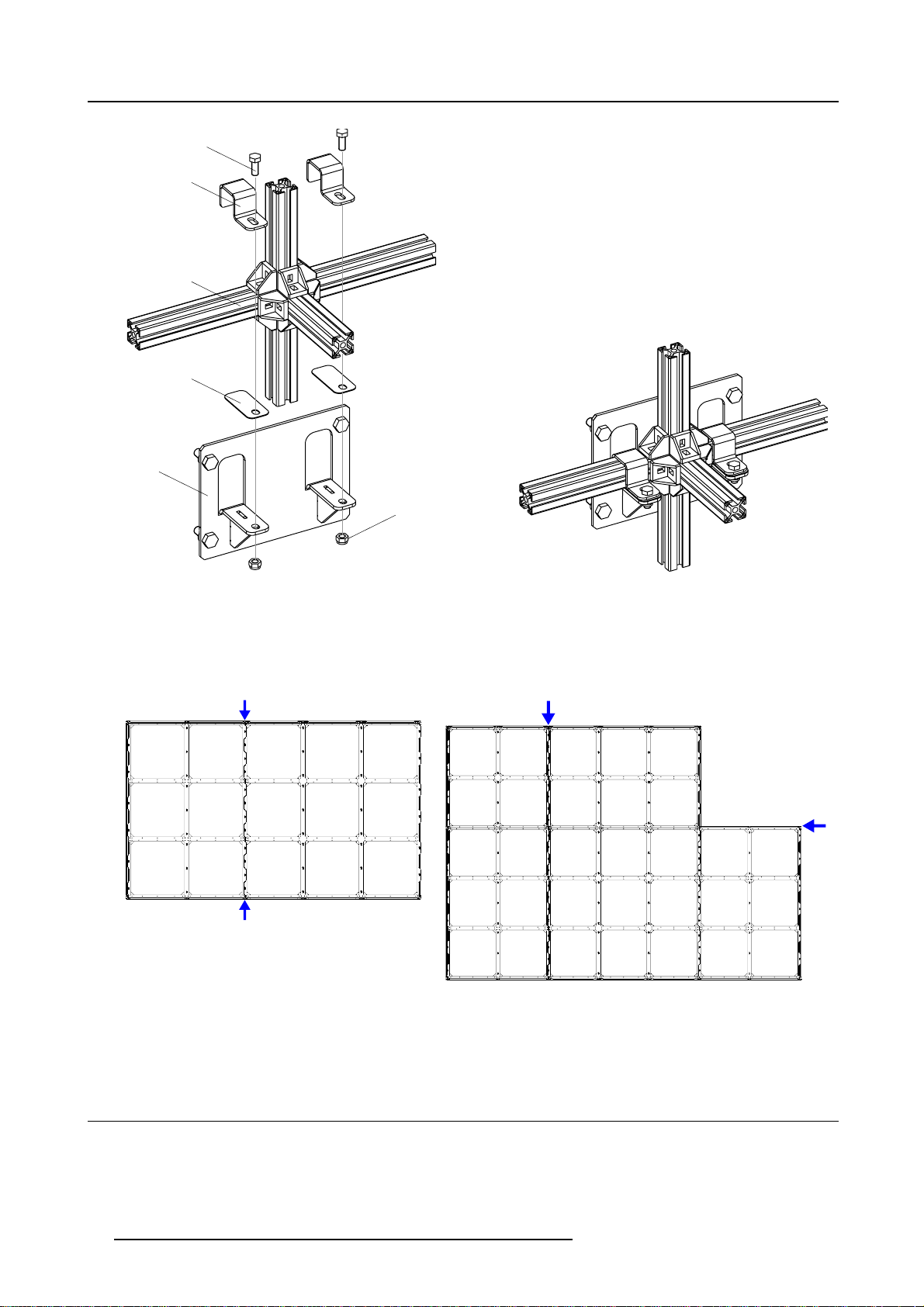
2. Fasten the first assembly block (coded x.1.1 see "Assembly block positioning code", page 19) into the lower left corner of the
support structure with the top of the assembly block up. Use tw o support brackets per attachment point. Make sure that the first
assembly block is perfectly aligned. Use shim plates for horizontal and vertical alignment. The support b rackets and the shim
plates are foreseen with slots to allow depth alignment. (image 3-13)
Note: It is very important that the first assembly block is perfectly a ligned, because all other assembly blocks are build on this
block.
3. Prepare the next assembly block, see "Preparation of the ILite assembly blocks", page 19.
4. Place the prepared assembly block into position on the support structure with the top of the assembly block up.
5. Fasten the assembly block, with aluminium corners and hammer bolts, to the other adjoining assembly block(s), see "Correct
alignment of the ILite assembly blocks", page 22. (image 3-14, image 3-15)
Note: For assembly reasons is it some times necessary to shift t he aluminium corners on the left s
to the right. Thisis done during preparation of the assembly blocks. If so, replace the aluminium corners to their original
position before fastening. This shift is necessary, otherwise it is impossible to place the assembly block against both
other joining a ssembly blocks.
6. Fasten the assembly block to the support s tructure using two support brackets with 2 M8 bolts and nuts pe r attachment point.
Use shim plates for horizontal and vertical alignment. The support brackets and the shim plates are foreseen with slots to allow
depth alignment.
7. Repeat step 3 and following steps until the wall is completed.
ide with approximately 3 cm
D
A
B
Image 3-12
A Mounting point on the support structure.
B Mounting plate.
C M10 bolt.
D M10 nut.
R5976522 FIXED ILITE DISPLAY 05042004
25
Page 30
3. Physical installation
E
D
C
B
A
F
Image 3-13
A Attached mounting plate on the support structure.
BShimplate.
C Assembly block.
D Support bracket.
E M8 bolt.
F M8 nut.
Vertical adjoining edge (A)
Image 3-14
Example 1: Mounting assemblyblock A.1.2 into a ILiteH7 x V5 display.
A Vertical adjoining edge.
Vertical adjoining edge
Image 3-15
Example 2: Mounting assembly block A.2.2 into a ILite H7 x V5 display.
A Vertical adjoining edge.
B Horizontal adjoini
ng edge.
(A)
Horizontal adjoining edge (B)
3.5 ILite tile mounting
What has to be done ?
ILite tile units are to be fixed into the wall assembly.
26
R5976522 FIXED ILITE DISPLAY 05042004
Page 31
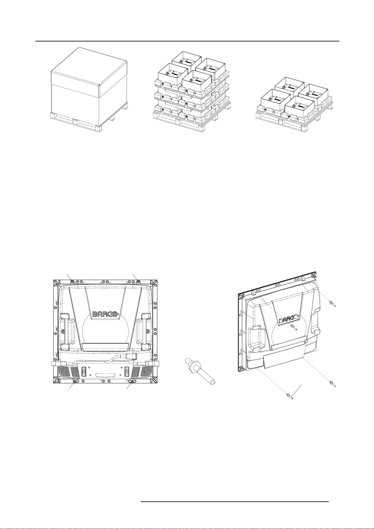
3. Physical installation
A
A
Image 3-16
ILite tiles pallet.
Necessary tools
• Wrench13mm.
• Wrench10mm.
Necessary parts
•ILitetiles.
• ILite tile positioning bolts.
• ILite tile lock nuts.
How to place an ILite tile into the wall assembly ?
1. Check if the tile is provided with 4 ILite tile positioning bolts. If not, insert those bolts first. (image 3-17)
2. Ensure the tile is in the right position, so top up.
3. Place the ILite tile into the wall assembly by guiding the positioning bolts through the corresponding positioning holes of the wall
assembly. (image 3-18)
4. Secure the ILite tile with 4 ILite tile lock nuts from the rear of the wall assembly.
B
B
A A
Image 3-17
A Location on ILite tile for positioning bol
B ILite tile positioning bolt.
R5976522 FIXED ILITE DISPLAY 05042004
ts.
27
Page 32
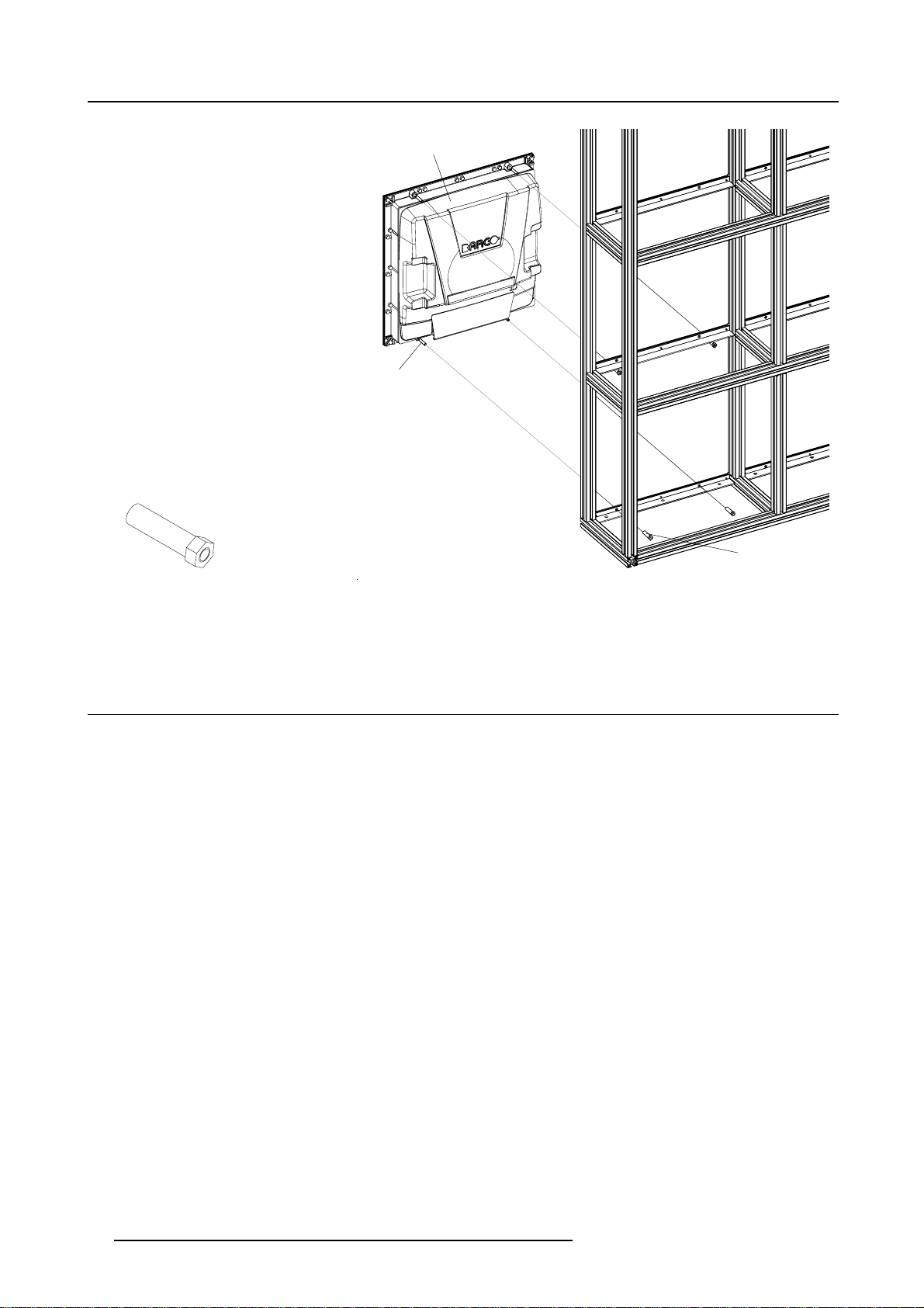
3. Physical installation
C
A
B
C
Image 3-18
A ILite tile top up.
B ILite tile positioning bolt.
C ILite tile lock nut.
3.6 C abling of the ILite display
3.6.1 ILite tile input/output ports
Input/output ports
There are tree connection ports on the back of each ILite tile. One power input port and two data input/output ports.
The data ports consist in two DVI connectors situated on the resync-unit. The resync-unit auto-detect the incoming signal on one
of the two DVI connectors. The other DVI connector will automatically act as data output port. So, it doesn’t matter on which DVI
connector the data is coming in, the ILite tile switch the functionality of the DVI co nnectors spontaneously between input and output.
The ILite tile is provided with power via a power linking cable with a C13 plug.
28
R5976522 FIXED ILITE DISPLAY 05042004
Page 33
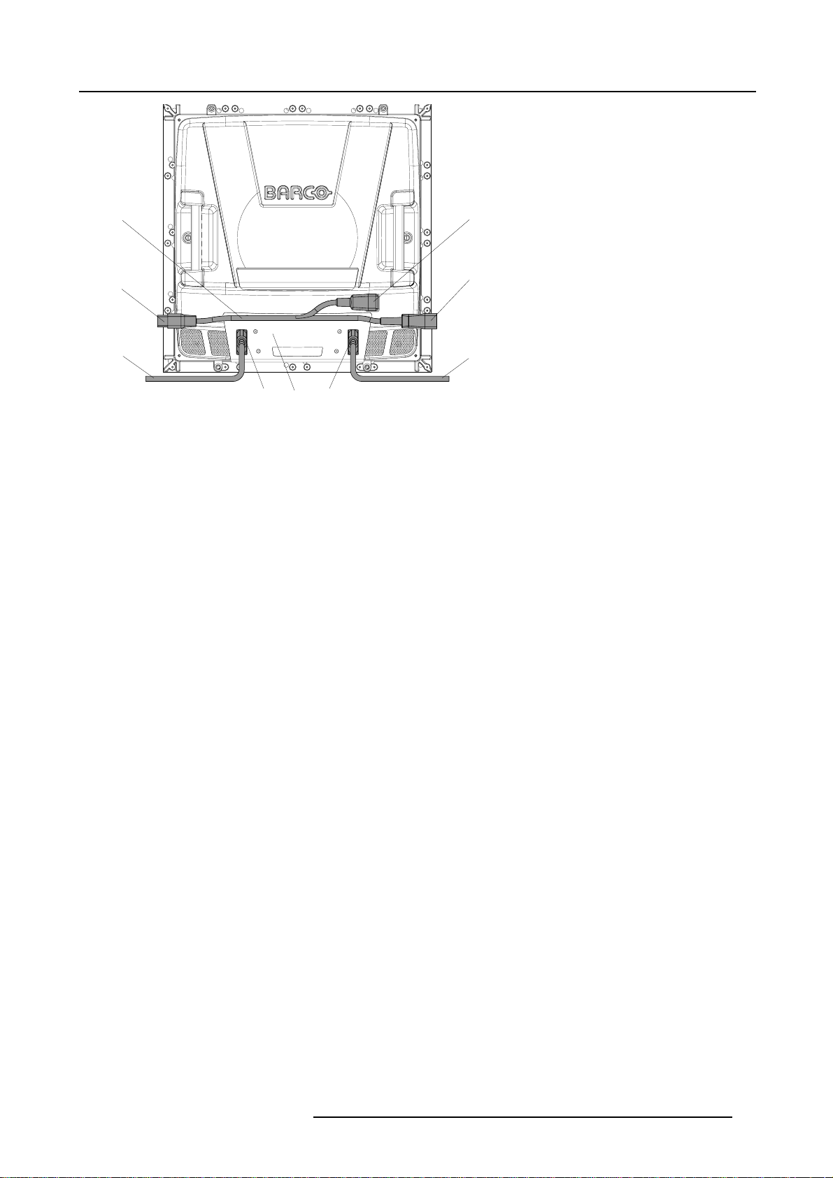
ABD
E
C
E
Image 3-19
A Power linking cable.
B Power input port.
C Power link to next tile (C19 plug).
D Power link from previous tile (C20 plug).
E Data input/output linking cable.
F DVI input/output connector.
G Resync-unit.
3. Physical installation
3.6.2 Power cabling
3.6.2.1 Connections with a Mono Phase Power Box
Necessary parts
• ILite Mono Phase Power Box.
• Power linking cables.
• Cable ties.
Power connections
1. Attach the ILite Mono Phase Power Box to the rear side of the ILite display.
2. Start creating pow er branches by connecting the output cables of the p ower box with the power linking c able of the lowest tile in
a column of maximum six. (image 3-20)
3. Complete each power branch by connecting maximum six tiles with power linking cables to each other in a daisy chain manner.
The female C13 plug of the power linking cable is plugged directly in the tile. The male C20 and the female C19 plugs serve as
power loop through. The last female C19 plug in the chain is unused.
Warning: Maximum 6 (six) tiles per power branch are allowed. Connecting more then six tiles with one output cable will over-
4. Attach long cables with cable ties to the frame.
5. Connect the power box with the local power-net. In case the local power net is not provided with a earthwire an additional earth
connection must be installed and connected with the protected earth inside the power box.
load the circuit.
R5976522 FIXED ILITE DISPLAY 05042004
29
Page 34
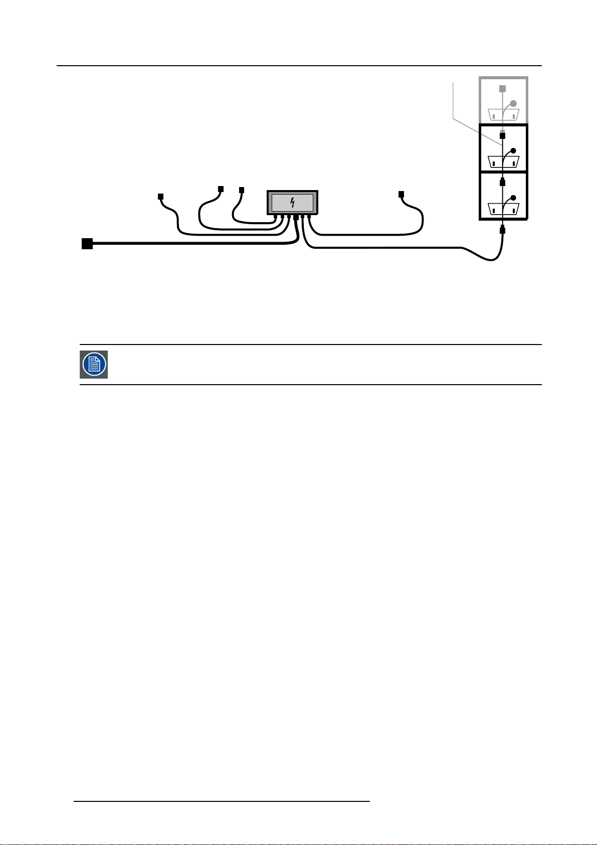
3. Physical installation
power
linking
calble
(C)
POWER
DATA
POWER
DATA
Image 3-20
A ILite Mono Phase Power Box.
B Ouput cable.
C Power Linking Cable.
D FIrst ILite tile in a column of m aximum six.
A power branch, consisting in a column of maximum six tiles, may be interrupted to provide a ILite display
peripheral from power. A maximum of one ILite display periphe
Mono Phase
Power Box
(A)
ILite
tile
(D)
DATA
Power source cable
(B)
ral is allowed per power branch of six tiles.
POWER
30 R5976522 FIXED ILITE DISPLAY 05042004
Page 35
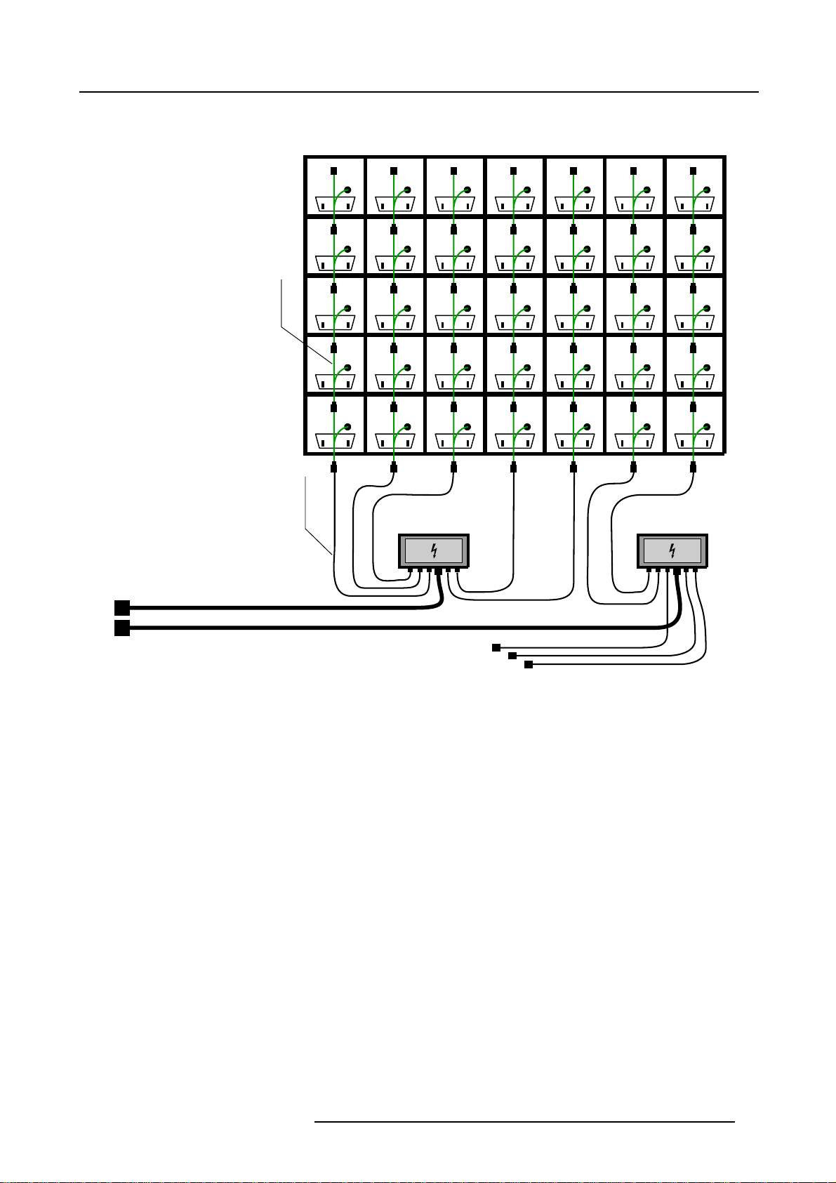
Example of power cabling with a ILite Mono Phase Power Box
3. Physical installation
Power
linking
cable
(D)
source
Power
cable
(C)
ILite display rear view
POWER
DATA
POWER
DATA
POWER
DATA
POWER
DATA
POWER
DATA
POWER
DATA
POWER
DATA
POWER
DATA
POWER
DATA
POWER
DATA
Mono Phase
Power Box
DATA
DATA
DATA
DATA
DATA
POWER
POWER
POWER
POWER
POWER
(B)
DATA
DATA
DATA
DATA
DATA
POWER
POWER
POWER
POWER
POWER
DATA
DATA
DATA
DATA
DATA
POWER
POWER
POWER
POWER
POWER
POWER
DATA
POWER
DATA
POWER
DATA
POWER
DATA
POWER
DATA
Mono Phase
Power Box
DATA
DATA
DATA
DATA
DATA
(A)
POWER
POWER
POWER
POWER
POWER
(B)
Image 3-21
A ILite Display rear view.
B ILite Mono Phase Power Box.
C Output cable.
D Power linking cable.
3.6.2.2 Connections with a Custom Power Box
Necessary parts
• Custom Power Box.
• Multi power cables.
• ILite Spider connector with Spider support bracket.
• Power linking cables.
• Cable ties.
Power connections
1. Install the Custom Power Box on a safe location near by the ILite display.
2. Connect a m ulti power cable, with an adapted length, with one of the multi pole connectors on the Custom Power Box. (im-
age 3-22)
3. Connect the other side of the multi power cable with an ILite Spider connector near by the ILite display. Use the Spider support
bracket to attach the Spider connector to the back side of the display wall. (image 3-23)
4. Start creating power branches by connecting the output cables of the ILite Spider connector with the power linking cable of the
lowest tile in a column of maximum six.
R5976522 FIXED ILITE DISPLAY 05042004
31
Page 36
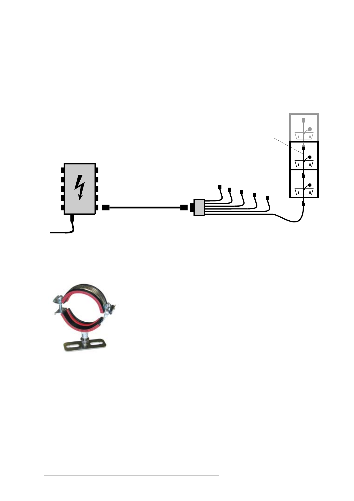
3. Physical installation
5. Complete each power branch by connecting maximum six tiles with power linking cables to each other in a daisy chain manner.
The female C13 plug of the power linking cable is plugged directly in the tile. The male C20 and the female C19 plugs serve as
power loop through. The last female C19 plug in the chain is unused.
Warning: Maximum 6 (six) tiles per power branch are allowed. Connecting more then six tiles with one output cable will over-
6. Attach long cables with cable ties to the frame.
7. Repeat step 2 and followings until all tiles are provide with power.
8. Connect the power box with the local power-net. In case the local power net is not provided with a earthwire an additional earth
connection must be installed and connected with the protected earth inside the power box.
load the circuit.
POWER
LINKING
CABLE
(E)
POWER
DATA
Custom Power
Box
(A)
MULTI POWER CABLE
(Multi pole)
Image 3-22
A Custom Power Box.
B Multi power cable (Multi pole).
C ILite Spider connector.
D First ILite tile in a column of maximum six.
E Power linking cable.
(B)
ILite Spider
Connector
(C)
ILite
Tile
(D)
POWER
DATA
POWER
DATA
Image 3-23
Spider support bracket.
3.6.3 Data cabling
Necessary parts
Data linking cables.
Data connections
1. Connect the data cable, coming from the digitizer, with one of the DVI connectors on the resync-unit of the first tile. The first tile
must be one of the tiles in the corner of the ILite display.
2. Complete the da ta path of the display by connecting all following tiles with data linking cables to each other in a daisy chain
manner. This daisy chain linking can be performed either in horizontal or vertical directions starting in a corner of the ILitedisplay.
3. Specify in the setup controlling software how the data linking of the tiles is realized (Horizontal or Vertical) and which tile is the
first in the chain.
32
R5976522 FIXED ILITE DISPLAY 05042004
Page 37
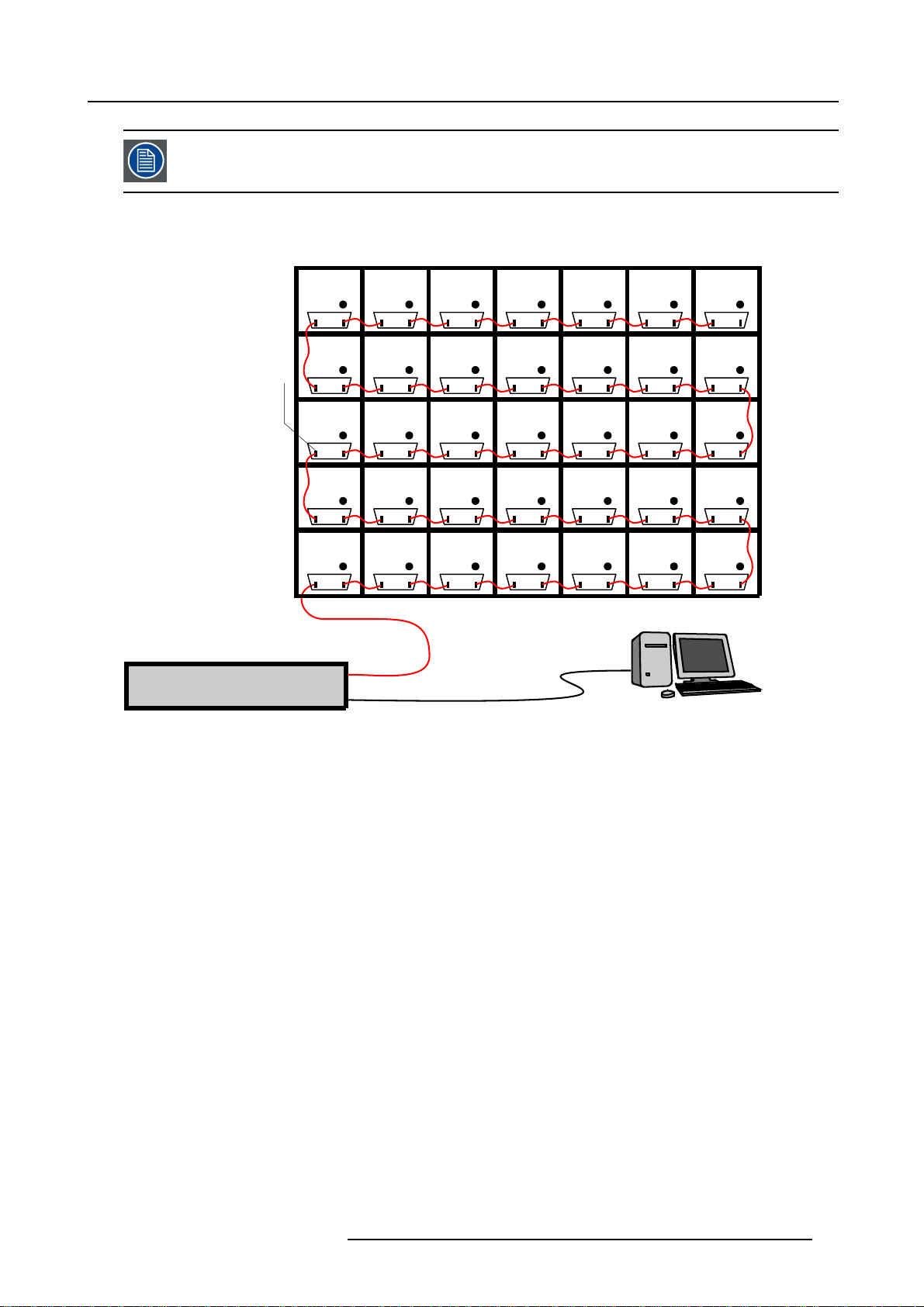
When using a Fiberlink System the fiberlink data connection is inserted between the digitizer and the first tile.
The Fiberlink Receiver is provided with a ’DATA IN’ and ’DATA OUT’ connector (MDR). Adapted data cables
delivered with the Fiberlin k system are required.
Example of data connections for an ILite H7xV5
ILite Display rear view
DATA
POWER
DATA
POWER
DATA
POWER
DATA
POWER
DATA
POWER
3. Physical installation
DATA
POWER
DATA
POWER
Last tile
will be in
a corner
(A)
DATA
POWER
DATA
POWER
Data cables are
daisy chained
to all tiles
(B)
First tile may
be in any corner
(C)
DIGITIZER
Image 3-24
DATA
DATA
DATA
POWER
POWER
POWER
LED
WALL
OUT
RS232
DATA
DATA
DATA
POWER
POWER
POWER
(D)
A Lasttilewillbeinacorner.
B Data cables are daisy chained to all tiles.
C First tile may be in anny corner.
D RS232 connection between Digitizer and control PC.
E Control PC containing control s oftware.
DATA
DATA
DATA
DATA
POWER
POWER
POWER
POWER
DATA
DATA
DATA
DATA
POWER
POWER
POWER
POWER
DATA
DATA
DATA
DATA
POWER
POWER
POWER
POWER
DATA
DATA
DATA
DATA
POWER
POWER
POWER
POWER
Control PC
DATA
DATA
DATA
DATA
POWER
POWER
POWER
POWER
(E)
R5976522 FIXED ILITE DISPLAY 05042004
33
Page 38
3. Physical installation
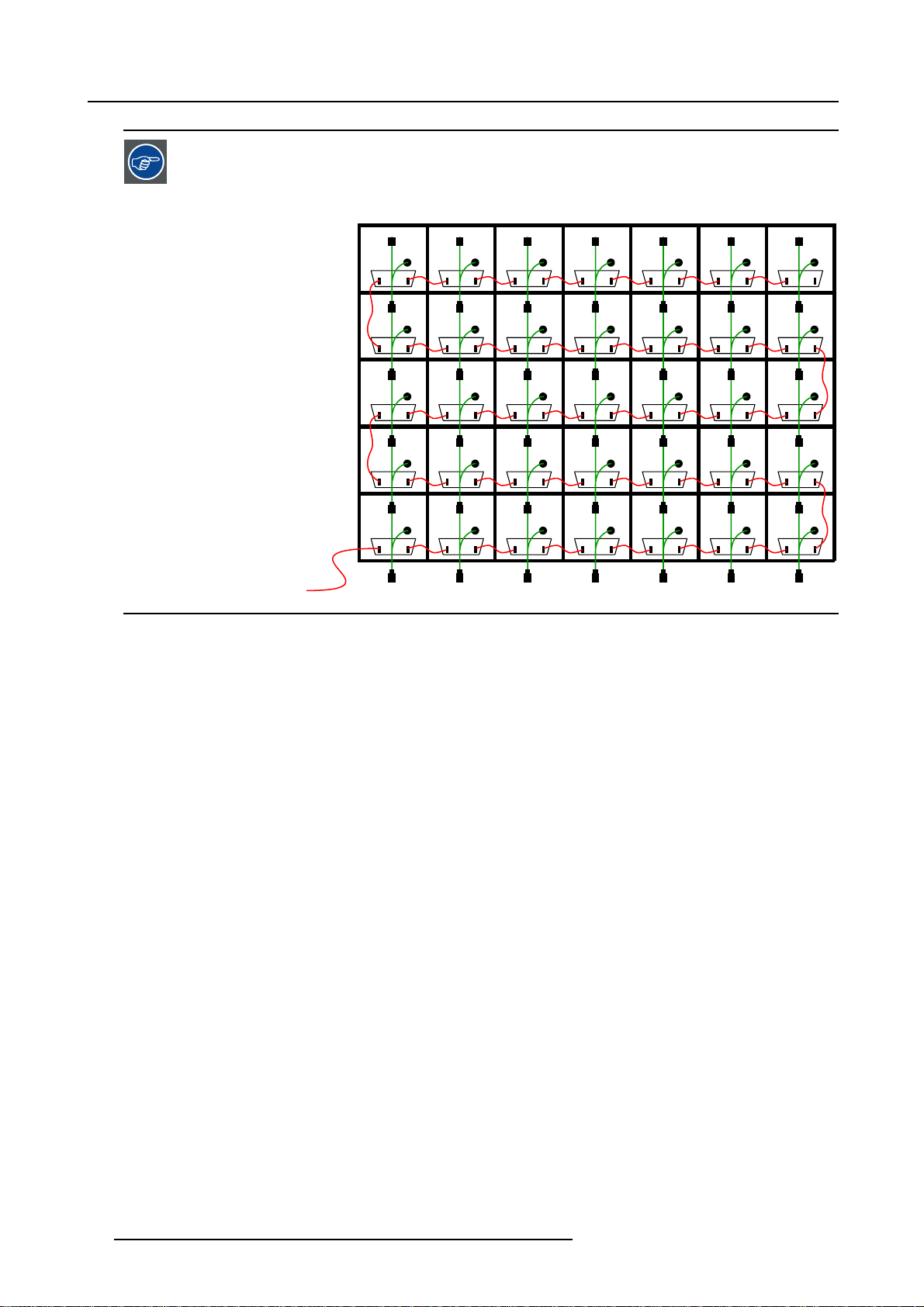
It’s recommended that the data cable interconnection got a direction at right angles to the power cable interconnection, b ecause the resync-unit is able to power up the data connection for the next 2 tiles. So, when 1
power branch is disabled, the data source connection is still accurate. It’s possible to interconnect the data
source cable horizontally or vertically, but for most installations the data source cabling is done in a horizontally direction because the power cablin g is done in vertical columns.
DATA
DATA
DATA
DATA
DATA
POWER
POWER
POWER
POWER
POWER
DATA
DATA
DATA
DATA
DATA
POWER
POWER
POWER
POWER
POWER
DATA
DATA
DATA
DATA
DATA
POWER
POWER
POWER
POWER
POWER
DATA
DATA
DATA
DATA
DATA
POWER
POWER
POWER
POWER
POWER
DATA
DATA
DATA
DATA
DATA
POWER
POWER
POWER
POWER
POWER
DATA
DATA
DATA
DATA
DATA
POWER
POWER
POWER
POWER
POWER
DATA
DATA
DATA
DATA
DATA
Image 3-25
POWER
POWER
POWER
POWER
POWER
34 R5976522 FIXED ILITE DISPLAY 05042004
Page 39
4. SERVICING
4.1 Safety instructions
Personal protection
4. Servicing
Image 4-1
Warning
Be aware of suspende
loads.
Image 4-2
Suspended loads
d loads, wear a hard hat to reduce the risk of personal injury. Mind your fingers while working with heavy
Image 4-3
Hard hat
Image 4-4
Mind your fingers
Safety precautions
• Fence off a res
to prevent any persons come near the LED-wall during servicing.
• Inspect the complete LED-wall for security, wear, deformation, corrosion, and any other circumstances that may effect the load
handling capability of the p art.
• Check the handles on the back of the tiles for loss of strength due to exposing to environmental conditions. Replace damaged
handles immediately before starting any servicing to the tiles.
• Do not modify and/or replicate any component. BARCO uses specific materials and manufacturing processes in order to
achieve part strength. No other parts then BARCO parts are allowed.
tricted area of at least 3 meters around the LED-wall using an eye-catching fence and “KEEP OUT” signs. This
4.2 ILite tile diagnostic
Status LED’s resync-unit
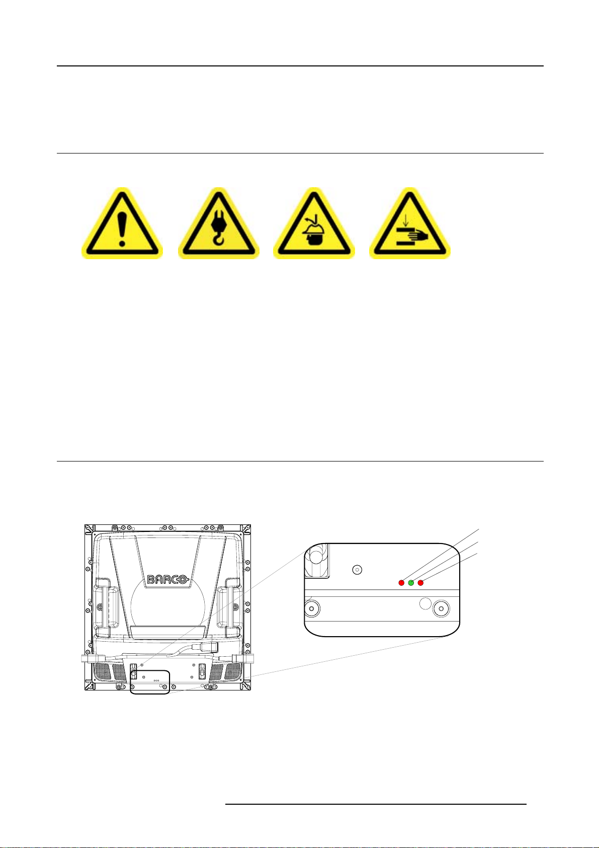
The resync-unitoftheILitetile is provided with tree statusLED’s. One green and two red LED’s. The LED’sarehorizontallymounted
he green LED in the middle. Th e green LED light up indicating the SMPS is started and the resync-unit is operating normally.
with t
The red LED’s indicate the status of the sync pulses and the incoming data signal.
Left red LED
Green LED
Right red LED
(A)
(B)
(C)
Image 4-5
A Left red LED.
B Green LED.
CRightredLED.
R5976522 FIXED ILITE DISPLAY 05042004
35
Page 40
4. Servicing
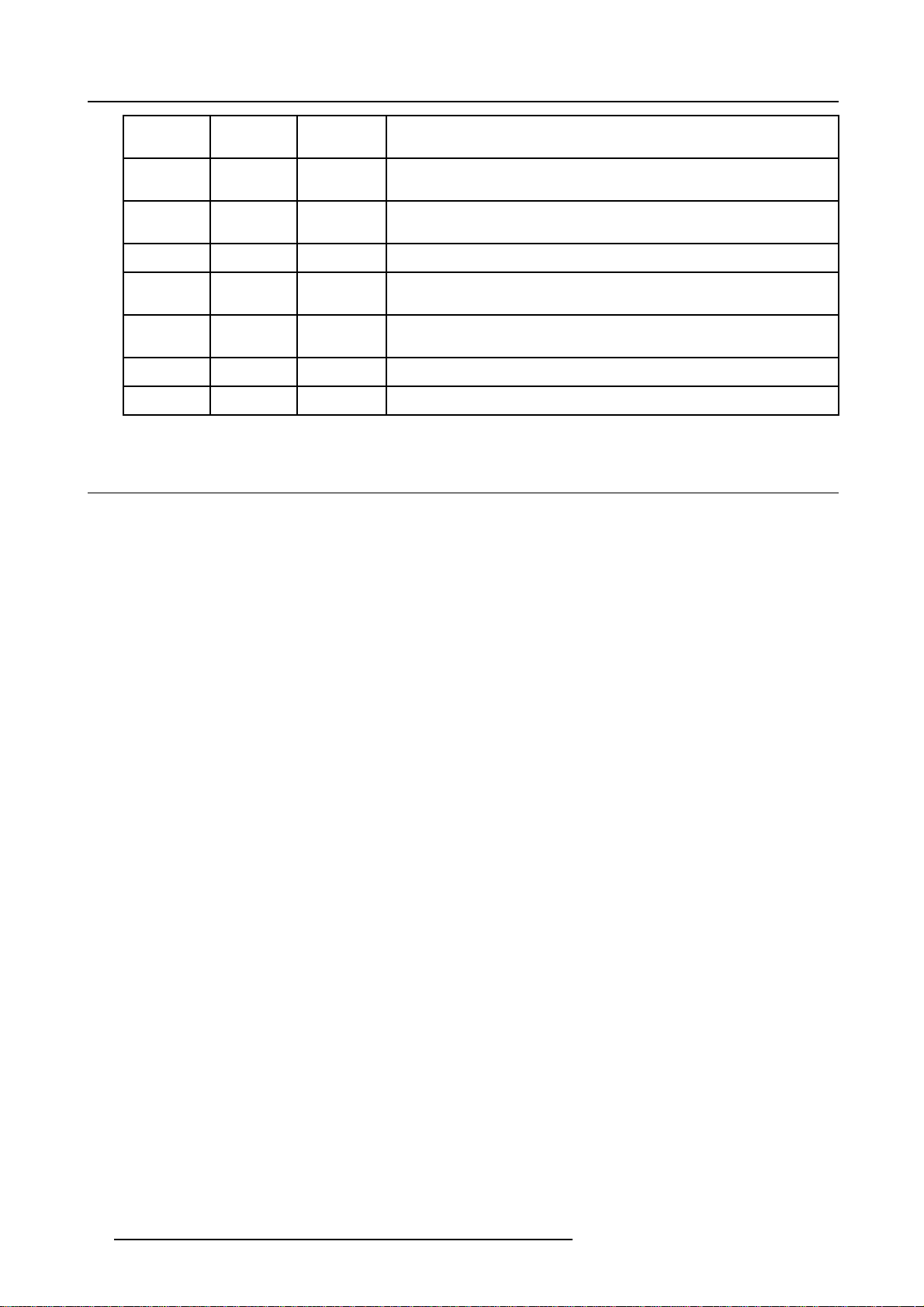
Left red
LED
Flashing
OFF ON
Flashing
ON ON OFF ILite tile is functioning normal, data signal and sync are received on the left
OFF ON ON ILite tile is functioning normal, data signal and sync are received on the right
OFF ON OFF The SMPS of the ILite tile is started but the resync-unit is mall functioning.
OFF OFF OFF The SMPS of the ILite tile is not started or the resync-unit is ma ll functioning.
Green LED
ON OFF ILite tile receives start-up signal on the left I/O port but no sync is present on
ON
Right red
LED
Flashing
Flashing ILite tile receive no start-up signal and no sync is present.
Diagnostic
the data signal.
ILite tile receives start-up signal on the right I/O port but no sync is present on
the data signal.
I/O port.
I/O port.
4.3 Tile accessing
What has to be done ?
Remove an ILite tile out of the assembly. To access an ILite tile after they have been installed can only be realized through back
access. There exist a work around procedure in case there is insufficientspaceatthebackoftheILitedisplay to remove an ILite tile.
Necessary tools
Wrench 10 mm.
How to remove a tile by accessing it from the back ?
1. Read an heed the servicing safety instructions.
2. Safely disconnect th e power and data cables to the tile.
3. Remove the four lock nuts on the ILite tile positioning bolts.
Warning: Be careful while removing the lock nuts that the tile doesn’t drop out at the front of the ILite display. Hold with one
4. Grab the ILite tile with both hands by the grip handles and push the tile a little forwards out of the ILite display. Hold tile securely.
5. Lay the tile flat on both arms and rotate it diagonally 45º.
6. Remove the tile by pulling it o
Work around in case of insuff
1. Read an heed the servicing safety instructions.
2. Start with the tile at the edge of de row wh ere the tile you w ant to remove is located. The back of the tiles at the edge of the ILite
display is accessible from the side when you stand in front of the ILite display.
3. Safely disconnect th e power and data cables to the tile.
4. Remove the four lock nuts on
Warning: Be careful while removing the lock nuts that the tile doesn’t drop out at the front of the ILite display. Hold with one
5. Gently push the tile from the back a little bit out of the wall assembly until you can grip the tile at the front.
6. Remove the tile by pulling
7. Repeat step 2 and followings on the next ILite tile in the row until the actually mall function tile is removed. The back of the next
tile is now accessible from his side.
hand the tile by one of the grip handles and remove with the other free hand the lock nuts.
ut of the assembly from the back.
icient space at the back ?
the ILite tile positioning bolts of the unplugged tile.
hand the tile inside the wall assembly and remove with the other free hand the lock nuts.
it out of the assembly from the front.
36
R5976522 FIXED ILITE DISPLAY 05042004
Page 41

4.4 H ot swap of an ILite tile
Necessary parts
• Flat blade screw driver.
• Wrench10mm.
How to hot swap an ILite tile ?
1. Read an heed the servicing safety instructions.
2. Disconnect th e power cord to the tile. Do not remove the power linking cable out of the power branch.
3. Remove the resync-unit from the tile by releasing two screws on the resync-unit.
4. Replace the mall function tile by accessing it from the back with an ot her tile (see "Tile accessing", page 36)
5. Place the resync-unit on the new tile and fasten with two screws.
6. Insert the power cord into the new tile.
4. Servicing
R5976522 FIXED ILITE DISPLAY 05042004
37
Page 42

4. Servicing
38 R5976522 FIXED ILITE DISPLAY 05042004
Page 43

INDEX
Index
A
Assembly blocks 8–9, 23
Attachment 23
Introduction 8
Order info 9
C
Cables 14, 17
Data 17
Power 14
Cabling 28
Correct alignment 22
D
Diagnostic 35
Dimensions 14
Tile 14
F
Fiberlink system 18
I
ILite 10 12
Specifications 12
ILite 12 13
Specifications 13
ILite 6 10
Specifications 10
ILite 6 XP 11
Specifications 11
ILite 8 12
Specifications 12
ILite tiles 10
Order info 10
Technical summary 10
ILite Tiles 9
Installation 19, 22, 26, 28–29, 32
Cabling 28
Correct alignment 22
Data cabling 32
Power cabling 29
Support structure 19
Tile input/output 28
Tile mounting 26
O
Order info 9–10
Assembly blocks 9
ILite tiles 10
Overview 18
Control software 18
Digitizer 18
Power boxes 18
P
Positioning code 19
Power 29, 31
Connections 29, 31
Custom Pow er Box 31
Mono Phase Power Box 29
Power boxes 18
Preparation 19
Positioning code 19
R
Removing sides 20–21
Bottom side 21
Left side 21
Which ? 20
Why ? 20
S
Safety 3–5, 35
Guidelines 3
Instructions 4, 35
Warnings 5
Servicing 35, 37
Diagnostic 35
Hot swap 37
Specifications 10–13
ILite 10 12
ILite 12 13
ILite 6 10
ILite 6 XP 11
ILite 8 12
Support structure 8
System 7–9
Assembly blocks 8
ILite Tiles 9
Introduction 7
Overview 7
Support structu re 8
T
Tile 14, 35–3 6
Access 36
Diagnostic 35
Dimensions 14
Tile access 36
Tile mounting 26
W
Warnings 5
R5976522 FIXED ILITE DISPLAY 05042004
39
 Loading...