

Page 1
Bar co iD H250/500
Owners manual
R9010520
R9010570
R59770079/00
11/05/2007
Page 2

Product revision
Firmware: V1.20
Barco nv Presentations
aan 5, 8520 Kuurne
Noordl
Phone: +32 56.36.82.11
Fax: +32 56.35.86.51
presentations.bid@barco.com
E-mail:
Visit us at the web: www.barco.com
PrintedinBelgium
Page 3

Changes
Barco provides this manual ’as is’ without warranty of any kind, either expressed or implied, including but not limited to the implied warranties or merchantability and fitness for a particular purpose. Barco may make improvements and/or changes to the product(s) and/or the
program(s) described in this publication at any time without notice.
This publication could contain technical inaccuracies or typographical errors. Changes are periodically made to the information in this
publication; these changes are incorporated in new editions of this publication.
Copyright ©
All rights reserved. No part of this document may be copied, reproduced or translated. It shall not otherwise be recorded, transmitted or
stored in a retrieval system without the prior written consent of Barco.
eCos
The software in this product uses eCos, the Embedded Configurable Operating System.
This is the license for eCos:
Copyright (C) 1998, 1999, 2000, 2001, 2002, 2003 Red Hat, Inc.
Copyright (C) 2002, 2003 John Dallaway
Copyright (C) 2002, 2003 Nick Garnett
Copyright (C) 2002, 2003 Jonathan Larmour
Copyright (C) 2002, 2003 Andrew Lunn
Copyright (C) 2002, 2003 Gary Thomas
Copyright (C) 2002, 2003 Bart Veer
eCos is free software; you can redistribute it and/or modify it under the terms of the GNU General Public License as published by the Free
Software Foundation; either version 2 or (at your option) any later version.
eCos isdistributed in the hope that it will be useful, but WITHOUT ANY WARRANTY; without eventhe
ITY or FITNESS FOR A PARTICULAR PURPOSE. See the GNU General Public License for more details.
You should have received a copy of the GNU General Public License along with eCos; if not, write to the Free Software Foundation, Inc.,
59 Temple Place, Suite 330, Boston, MA 02111-1307 USA.
As a special exception, if other files instantiate templates or use macros or inlin
with other works to produce a work based on this file, this file does not by itself cause the resulting work to be covered by the GNU General
Public License. However the source code for this file must still be made available in accordance with section (3) of the GNU General Public
License.
This exception does not invalidate any other reasons why a work based on this file might be covered by the GNU General Public License.
The eCos source used to build the software used in the Barco iCon is available on request from Barco.
e functions from this file, or you compile this file and link it
implied warranty ofMERCHANTABIL-
EN55022/CISPR22 Class A ITE (Information Technology Equipment)
Class A ITE is a category of all other ITE which satisfies the class A ITE limits but not the class B ITE limits. Such equipment should not
be restricted in its sale but the following warning shall be included in the instructions for use:
Warning : This is a class A product. In a domestic environment this prod
required to take adequate measures.
uct may cause radio interference in which case the user may be
Guarantee and Compensation
Barco provides a guarantee relating to perfect manufacturing as part of the legally stipulated terms of guarantee. On receipt, the purchaser
must immediately inspect all delivered goods for damage incurred during transport, as well as for material and manufacturing faults Barco
must be informed immediately in writing of any complaints.
The period of guarantee begins on the date of transfer of risks, in the case of special systems and software on the date of commissioning,
at latest 30 days after the transfer of risks. In the event of justified notice of complaint, Barco can repair the fault or provide a replacement
at its own discretion within an appropriate period.
reduction in the purchase price or cancellation of the contract. All other claims, in particular those relating to compensation for direct or
indirect damage, and also damage attributed to the operation of software as well as to other services provided by Barco, being a component
of the system or independent service, will be dee
guaranteed in writing or due to the intent or gross negligence or part of Barco.
If this measure proves to be impossible or unsuccessful, the purchaser can demand a
med invalid provided the damage is not proven to be attributed to the absence of properties
Page 4

If the purchaser or a third party carries out modifications or repairs on goods delivered by Barco, or if the goods are handled incorrectly,
in particular if the systems are commissioned operated incorrectly or if, after the transfer of risks, the goods are subject to influences not
agreed upon in the contract, all guarantee claims of the purchaser will be rendered invalid. Not included in the guarantee coverage are
system failures which are attributed to programs or special electronic circuitry provided by the purchaser, e.g. interfaces. Normal wear as
well as normal maintenance are not subject to the guarantee provided by Barco either.
The environmental conditions as well as the servicing and maintenance regulations specified in the this manual must be complied with by
the customer.
Trademarks
Brand and product names mentioned in this manual may be trademarks, registered trademarks or copyrights of their respe
All brand and product names mentioned in this manual serve as comments or examples and are not to be understood as advertising for
the products or their manufactures.
ctive holders.
Page 5

Table of contents
TABLE OF CONTENTS
1. Packaging............................................................................................................ 3
1.1 Unpacking ............................................................................................................................ 3
2. Installation guidelines ............................................................................................. 5
2.1 Safetywarnings....................................................................................................................... 5
2.2 Installation guidelines ................................................................................................................ 5
3. Installation........................................................................................................... 7
3.1 Battery installation in the RCU ....................................................................................................... 8
3.2 Lens installation . . .................................................................................................................... 8
3.3 Removing thelens.................................................................................................................... 9
3.4 Lens range . ........................................................................................................................... 9
3.5 Lens Formulas . . .. ...................................................................................................................10
3.6 Projectorconfiguration ..............................................................................................................10
3.7 Positioningtheprojector............................................................................................................. 11
4. Connections........................................................................................................15
4.1 Power connection ...................................................................................................................15
4.2 Signal connections . . . ...............................................................................................................15
4.2.1 The inputsection..............................................................................................................15
4.2.2 Connecting a Composite video signal. . . .....................................................................................17
4.2.3 Connecting an S-Video signal ................................................................................................17
4.2.4 Connecting an RGB signal . . .................................................................................................18
4.2.5 Connecting a Component Video signal . .....................................................................................19
4.2.6 Connecting a DVI signal .. ....................................................................................................19
4.2.7 Connecting a computer signal . .. ............................................................................................20
4.2.8 The DVI output................................................................................................................20
4.3 Communication connections .. . . ....................................................................................................21
4.3.1 RS232/RS422 Connections . . ................................................................................................22
4.3.2 Ethernet Connections . . . . . ....................................................................................................22
5. Setup ................................................................................................................25
5.1 RCU& Localkeypad................................................................................................................25
5.2 Terminologyoverview ...............................................................................................................27
5.3 Switching on.........................................................................................................................28
5.4 Setting up the RCU address . . . . ....................................................................................................29
5.5 Setting up the projector address (only if necessary) . . .............................................................................30
5.6 Setting upthe orientation ...........................................................................................................31
5.7 Adjusting the lens....................................................................................................................31
5.8 Setup the baudrate for serial communication. . .....................................................................................33
5.9 Network settings.....................................................................................................................34
5.10 Preferences..........................................................................................................................35
5.10.1 Language setting. . . ...........................................................................................................35
5.10.2 Automaticstartup .............................................................................................................36
6. Getting started.....................................................................................................39
6.1 Start up ..............................................................................................................................39
6.2 Selecting a source...................................................................................................................39
6.3 Adjusting the image .................................................................................................................39
7. Advanced ...........................................................................................................41
7.1 TheOSDMenu ..................................................................................................................... 41
7.2 Using theDialogboxes..............................................................................................................42
7.3 Sourceselection.....................................................................................................................43
7.3.1 Source selection .............................................................................................................. 43
7.3.2 Composite video .............................................................................................................43
7.3.3 S-Video........................................................................................................................44
7.3.4 RGB-YUV .....................................................................................................................44
7.3.5 PC .............................................................................................................................45
7.3.6 DVI ............................................................................................................................45
7.4 General ..............................................................................................................................46
7.4.1 Pause..........................................................................................................................47
7.4.2 Freeze.........................................................................................................................47
7.4.3 Identification ...................................................................................................................47
7.5 Image ................................................................................................................................48
7.5.1 Imagesettings ................................................................................................................49
7.5.1.1 Setting theContrast ...................................................................................................49
7.5.1.2 Setting theBrightness..................................................................................................49
7.5.1.3 Color....................................................................................................................50
7.5.1.4 Tint(NTSCvideo signals only).........................................................................................50
7.5.1.5 Sharpness .. . ...........................................................................................................51
7.5.1.6 Gamma ................................................................................................................51
7.5.1.7 Phase(RGB signalsonly)..............................................................................................52
R59770079 BARCO ID H250/500 11/05/2007
1
Page 6

Table of contents
7.5.1.8 Noise Reduction (only for video signals) . .............................................................................52
7.5.2 Aspect ratio ...................................................................................................................53
7.5.3 Colortemperature.............................................................................................................55
7.5.4 Film modedetection (video only).............................................................................................57
7.5.5 Input balance . .. ...............................................................................................................58
7.5.6 Automatic gain control (AGC) ................................................................................................61
7.5.7 Manual gain control ...........................................................................................................62
7.6 Lamp management . . . ...............................................................................................................62
7.6.1 Runtimes .....................................................................................................................63
7.6.2 Lamp mode ...................................................................................................................63
7.6.3 History.........................................................................................................................65
7.6.4 Resetlamp Runtime ..........................................................................................................65
7.6.5 Clearlamp error...............................................................................................................66
7.6.6 Lamp runtimewarning ........................................................................................................67
7.7 Image files ...........................................................................................................................68
7.7.1 Introduction to Imagefiles....................................................................................................68
7.7.2 Load file . . . . ...................................................................................................................69
7.7.3 Forced file load................................................................................................................70
7.7.4 Auto Image....................................................................................................................71
7.7.5 Edit file ........................................................................................................................72
7.7.6 Save as(create a custom file)................................................................................................75
7.7.7 Rename file ...................................................................................................................75
7.7.8 Copy...........................................................................................................................76
7.7.9 Delete .........................................................................................................................77
7.8 Display setup ........................................................................................................................78
7.8.1 Dynacolor™...................................................................................................................78
7.8.2 Brilliant Color
7.8.3 Full screen synchronous representation .....................................................................................88
7.8.4 Text box .......................................................................................................................88
7.8.5 Menu bar position.............................................................................................................89
7.8.6 Status bar position............................................................................................................89
7.8.7 Sliderbox position.............................................................................................................90
7.8.8 Softedge . . .. ...................................................................................................................90
7.8.8.1 Softedge Border .. . .....................................................................................................91
7.8.8.2 Blacklevel..............................................................................................................92
TM
mode ........................................................................................................87
8. Maintenance........................................................................................................93
8.1 Cleaning the lens ....................................................................................................................93
9. Image files..........................................................................................................95
9.1 Image files ...........................................................................................................................95
10. Troubleshooting................................................................................................... 99
10.1 Using the OSD.......................................................................................................................99
Index.................................................................................................................... 101
2 R59770079 BARCO ID H250/500 11/05/2007
Page 7
1. PACKAGING
8
1.1 Unpacking
CEE7
European power plug to connect the power cord to the wall outlet.
ANSI 73.11
American power plug to connect the power cord to the wall outlet.
Content
• 1 projector (weight ± 14 kg or 31 lbs)
• 1 remote control unit RCU + 2 batteries.
• 2 power cables with outlet plug type CEE7 and ANSI 73.11.
• 1 owners manual
• 1 safety manual
• 1 CDROM (containing manuals)
1. Packaging
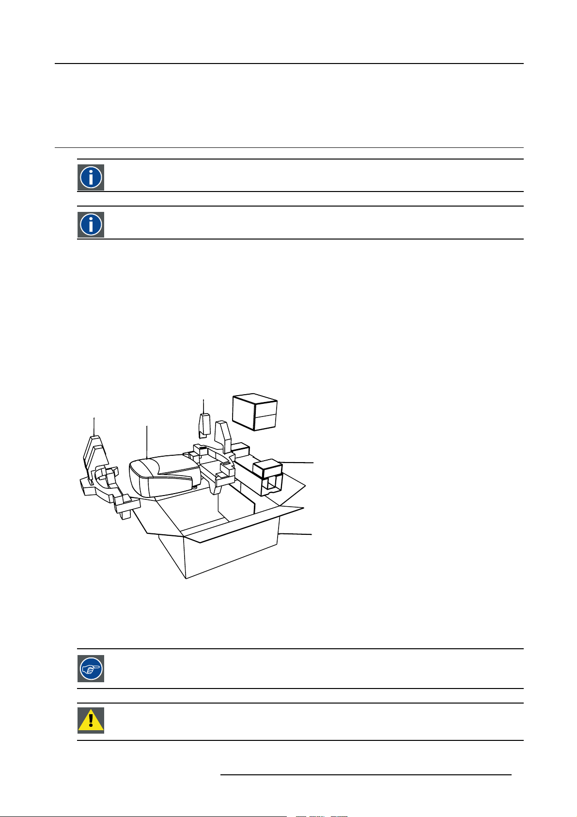
Form
The projector is packed in a carton box. To provide protection during transportation, the projector
package is secured with banding and fastening clips.
R824561
R824562
Projector
R824518
(+ cable basket R72440
R825784
Image 1-1
Lens packaging
The Lens is supplied as an individual item.
Thelensispackedinacartonbox.
is surrounded with foam. The
Save the original shipping carton and packing material, they will be necessary if you ever have to transport
the lens.
CAUTION: Never transport the projector with the lens mounted on it !
Always remove the lens b efo re transporting the projector.
R59770079 BARCO ID H250/500 11/05/2007 3
Page 8
1. Packaging
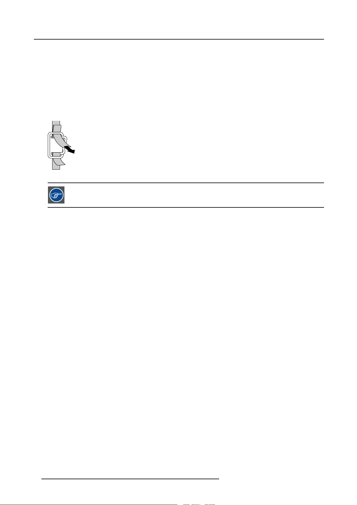
How to unpack the projector
1. Release the cord straps. (image 1-2)
2. Remove the assembly from the pallet
3. Remove the cardboard cover
4. Remove the large cardboard
5. Remove the 8 foam parts
6. Loosen and remove the 3 screws spacers fixing the projector to the wooden board
7. Remove the projector from the board
PULL
TO OPE
Image 1-2
Save the original shipping carton and packing material, they will be necessary if you ever have to ship your
projector. For maximum protection, repack your projector as it was originally packed at the factory.
4 R59770079 BARCO ID H250/500 11/05/2007
Page 9
2. Installation guidelines
2. INSTALLATION GUIDELINES
Overview
• Safety warnings
• Installation guidelines
2.1 Safety warnings
WARNING: Before installing the projector, read first the safety instructions in the safety manual (R5975258)
delivered with the projector.
Insure that the projector is installed in an easy to evacuate room in case of a lamp explosion.
Mercury Vapor Warnings
Keep the following warnings in mind when using the projector. The lamp used in the projector contains mercury. In case of a lamp
rupture, explosion there will be a mercury vapor emission. In order to minimize the potential risk of inhaling mercury vapors:
• Ensure the projector is installed only in ventilated rooms.
• Replace the lamp module before the end of its operational life.
• Promptly ventilate the room after a lamp rupture, explosion has occurred, evacuate the room (particularly in case of a pregnant
woman).
• Seek medical attention if unusual health conditions occur after a lamp rupture, explosion, such as headache, fatigue, shortness
of breath, chest-tightening coughing or nausea.
2.2 Installation guidelines
Ambient temperature check
Careful consideration of things such as image size, ambient light level, projector placement and type of screen to use are critical to
the optimum use of the projection system.
Max. ambient temperature : 40 °C or 104 °F
Min. ambient temperature : 0 °C or 32 °F
The projector will not operate if ambient air temperature falls outside this range (0°C- 40°C or 32°F-104°F).
Environment
Do not install the projection system in a site near heat sources such as radiators or air ducts, or in a place subject to direct sunlight,
excessive dust or humidity. Be aware that room heat rises to the ceiling; check that temperature near the installation site is not
excessive
CAUTION: Harmful Environmenta l Contamination Precaution
Environment condition check
A projector must always be mounted in a manner which ensures the free flow of clean air into the projectors ventilation inlets as well
as free flow at the ventilation outlets. The installation must also allow easy access to the consumable parts ( dustfilters, lamps, ...)
For installations in environments where the projector is subject to airborne contaminants such as that produced by smoke machines
or similar (these deposit a thin layer of greasy residue upon the projectors internal optics and imaging electronic surfaces, degrading
performance), then it is highly advisable and desirable to have this contamination removed prior to it reaching the projectors clean
air supply. Devices or structures to extract or shield contaminated air well away from the projector are a prerequisite, if this is not
a feasible solution then measures to relocate the projector to a clean air environment should be considered. Make sure that the
projector never runs with dirty dustfilters as this will dramatically reduce the lifetime of the consumables. It is advised to clean the
dustfilters on a regular basis and to replace them at any lamp change. Barco reserves itself the right to refuse warranty replacement
of consumables if they have been used in a projector with dirty airfilters. Only use the manufactures recommended cleaning kit which
has been specifically designed for cleaning optical parts, never use industrial strength cleaners on a projectors optics as these will
degrade optical coatings and damage sensitive optoelectronics .
Failure to take suitable precautions
nate in extensive and irreversible ingrained optical damage. At this stage cleaning of the internal optical units will be non-effective
and impracticable. Damage of this nature is under no circumstances covered under the manufactures warranty and may deem the
to protect the projector from the effects of persistent and prolonged air contaminants will culmi-
R59770079 BARCO ID H250/500 11/05/2007
5
Page 10

2. Installation guidelines
warranty null and void. In such a case the client shall be held solely responsible for all costs incurred during any repair. It is the
clients responsibility to ensure at all times that the projector is protected from the harmful effects of hostile airborne particles in the
environment of the projector. The manufacture reserves the right to refuse warranty repair if a projector has been subject to wantful
neglect, abandon or improper use.
What about ambient light ?
The ambient light level of any room is made up of direct or indirect sunlight and the light fixtures in the room. The amount of ambient
light will determine how bright the image will appear. So, avoid direct light on the screen. Windows that face the screen should be
covered by opaque drapery while the set is being viewed. It is desirable to install the projection system in a room whose walls and
floor are of non-reflecting material. The use of recessed ceiling lights and a method of dimming those lights to an acceptable level
is also important. Too much ambient light will ‘wash out’ of the projected image. This appears as less contrast between the darkest
and lightest parts of the image. With bigger screens, the ‘wash out’ becomes more important. As a general rule, darken the room to
the point where there is just sufficient light to read or write comfortably. Spot lighting is desirable for illuminating small areas so that
interference with the screen is minimal.
Which screen type ?
There are two major categories of screens used for projection equipment. Those used for
projection applications. Screens are rated by how much light they reflect (or transmit in the case of rear projection systems) given a
determined amount of light projected toward them. The ‘GAIN’ of a screen is the term used. Front and rear screens are both rated
in terms of gain. The gain of screens range from a white matte screen with a gain of 1 (
gain of 10 (x10) or more. The choice between higher and lower gain screens is largely a matter of personal preference and another
consideration called the Viewing angle. In considering the type of screen to choose, determine where the viewers will be located
and go for the highest gain screen possible. A high gain screen will provide a
more information about screens, contact your local screen supplier.
brighter picture but reduce the viewing angle. For
front projected images and those for rear
x1) to a brushed aluminized screen with a
Image size
The projector is designed for projecting an image size with a screenwidth from 1.00m (3.3ft) to 6.00m (19.7ft) with an aspect ratio of
16 to 9.
6
R59770079 BARCO ID H250/500 11/05/2007
Page 11
3. INSTALLATION
L
ith diff
Overview
• Battery installation in the RCU
• Lens installation
• Removing the lens
• Lens range
• Lens Formulas
• Projector configuration
• Positioning the projector
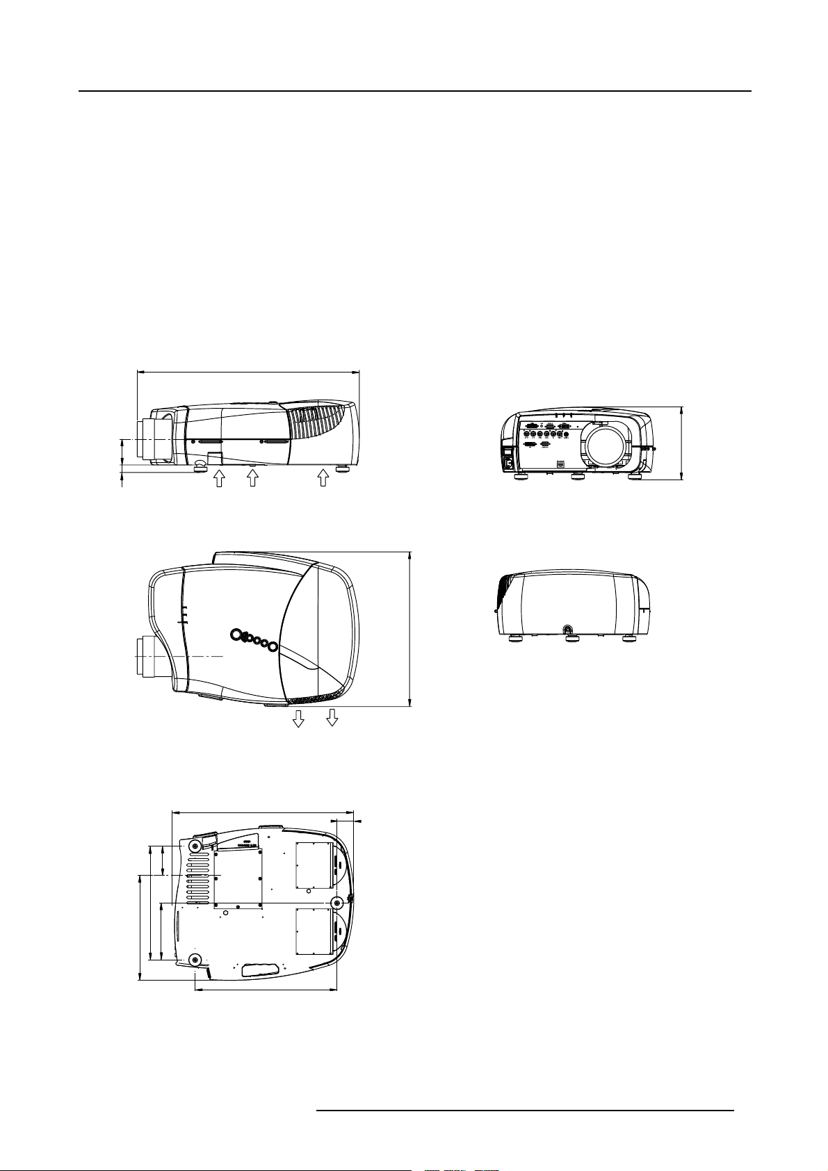
Dimensions
Dimensions are given in mm and inch ( 1inch = 25.4 mm)
ength w
erent lenses : see table
3. Installation
69
20
Cold air IN
487 (length without Cable Basket)
Cold air IN
415
Cold air OUT
45
195
78
305
281
152
Image 3-1
380
R59770079 BARCO ID H250/500 11/05/2007 7
Page 12
3. Installation
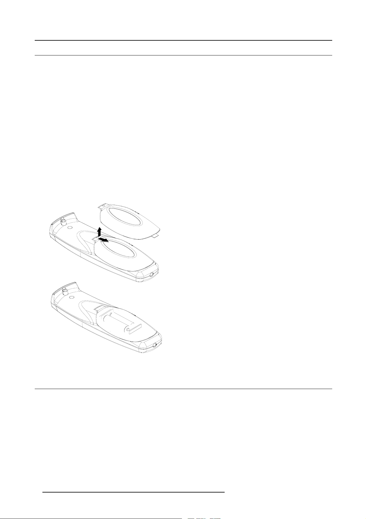
3.1 Battery installation in the RCU
How to install the battery
Two batteries are packed together with the RCU. Before using your RCU, install first these batteries.
1. Remove the battery cover on the backside by pushing the handle a little towards the bottom of the RCU.
2. Lift up the top side of the cover at the same time.
3. Insert the batteries as indicated in the RCU.
4. Put the battery cover on its place.
How to replace the batteries in the RCU
To replace the batteries :
1. Remove the battery cover on the backside by pushing the handle a little towards the bottom of the RCU.
2. Lift up the top side of the cover at the same time.
3. Push on the + side of the battery towards the - side
4. Lift up the battery at the same time.
5. Repeat for the second battery.
6. Insert the batteries as indicated in the RCU (battery type AA or LR6 or equivalent).
7. Put the battery cover on its place. (image 3-2)
Image 3-2
3.2 Lens installation
How to install ?
1. Take the lens out of its packing material
2. Fix the lens by placing it in the housing (image 3-3)
Note: In case of a motorized lens the female jack must b e in front of the male jack located in the upper-left part of the housing
in the projector
3. Push carefully to lock the lens in the housing
8
R59770079 BARCO ID H250/500 11/05/2007
Page 13
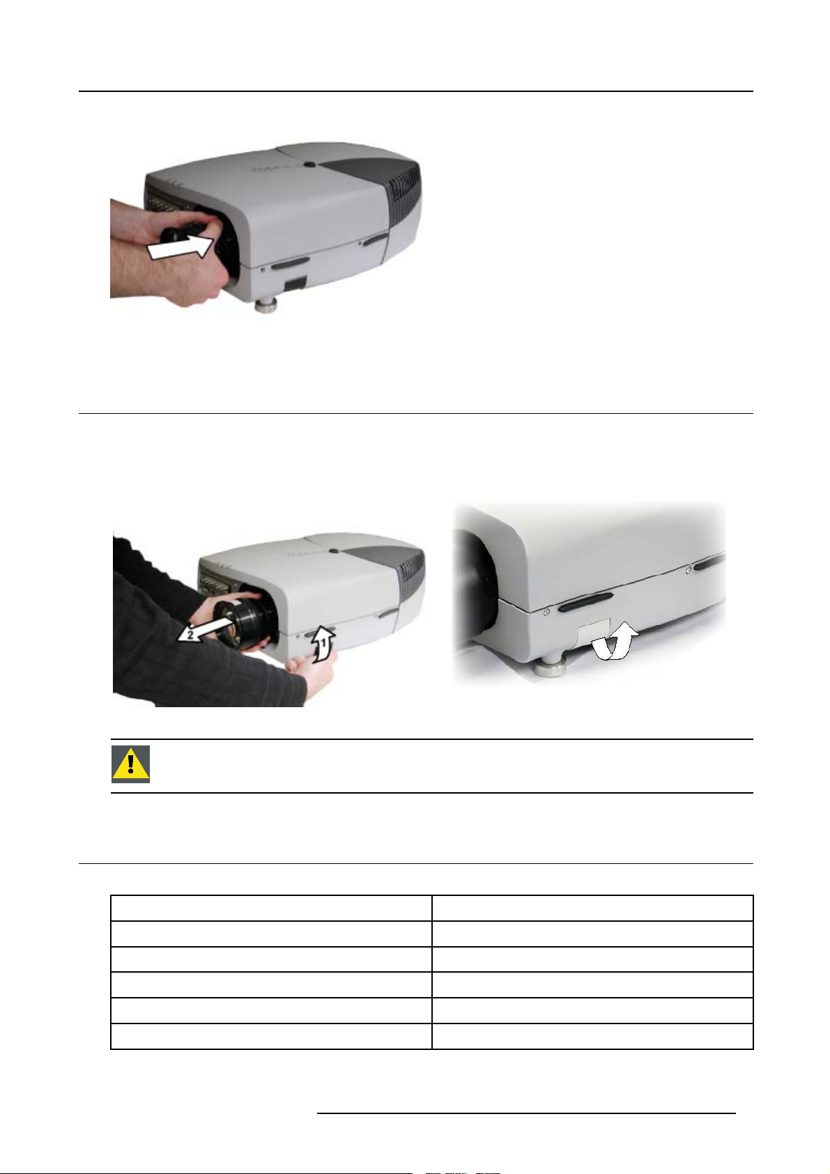
Image 3-3
3.3 Removing the lens
How to remove the lens ?
1. Unlock the lens by pulling the handle located on the right side of the projector (image 3-4, image 3-5)
2. Remove the lens out of its housing
3. Installation
Image 3-4
CAUTION: Never transport the projector with the lens mounted on it !
Always remove the lens b efo re transporting the projector.
3.4 Lens range
Overview table
Lens
QCLD (0.85:1)
QCLD (1.1-1.3:1)
CLD (1.2-1.6:1)
CLD (1.6-2.4:1)
CLD (2.4-4.3:1)
Image 3-5
location of the lens handle
Partnumber
R9849860
R9849850
R9849870
9849880
R
R9849890
R59770079 BARCO ID H250/500 11/05/2007 9
Page 14
3. Installation
See the Maintenance appendix for more information about lens cleaning.
3.5 Lens Formulas
Formulas
Lenses
Metric Formulas (meter) Inch formulas (inch)
QCLD (0.85:1) PD=0.79XSW+0.06 PD = 0.79 X SW + 2.36
QCLD (1.1-1.3:1) PD
CLD (1.2-1.6:1) PD
CLD (1.6-2.4:1) PD
CLD (2.4-4.3:1) PD
=1.02XSW+0.05
min
=1.2XSW+0.06
PD
max
= 1.1 X SW + 0.02
min
=1.51XSW+0.02
PD
max
=1.46XSW+0.00
min
= 2.21 X SW - 0.02
PD
max
= 2.2 X SW - 0.03
min
= 3.99 X SW - 0.01
PD
max
PD
=1.02XSW+1.97
min
= 1.2 X SW + 2.36
PD
max
PD
=1.1XSW+0.79
min
=1.51XSW+0.79
PD
max
PD
=1.46XSW+0.00
min
= 2.21 X SW - 0.79
PD
max
PD
= 2.2 X SW - 1.18
min
= 3.99 X SW - 0.39
PD
max
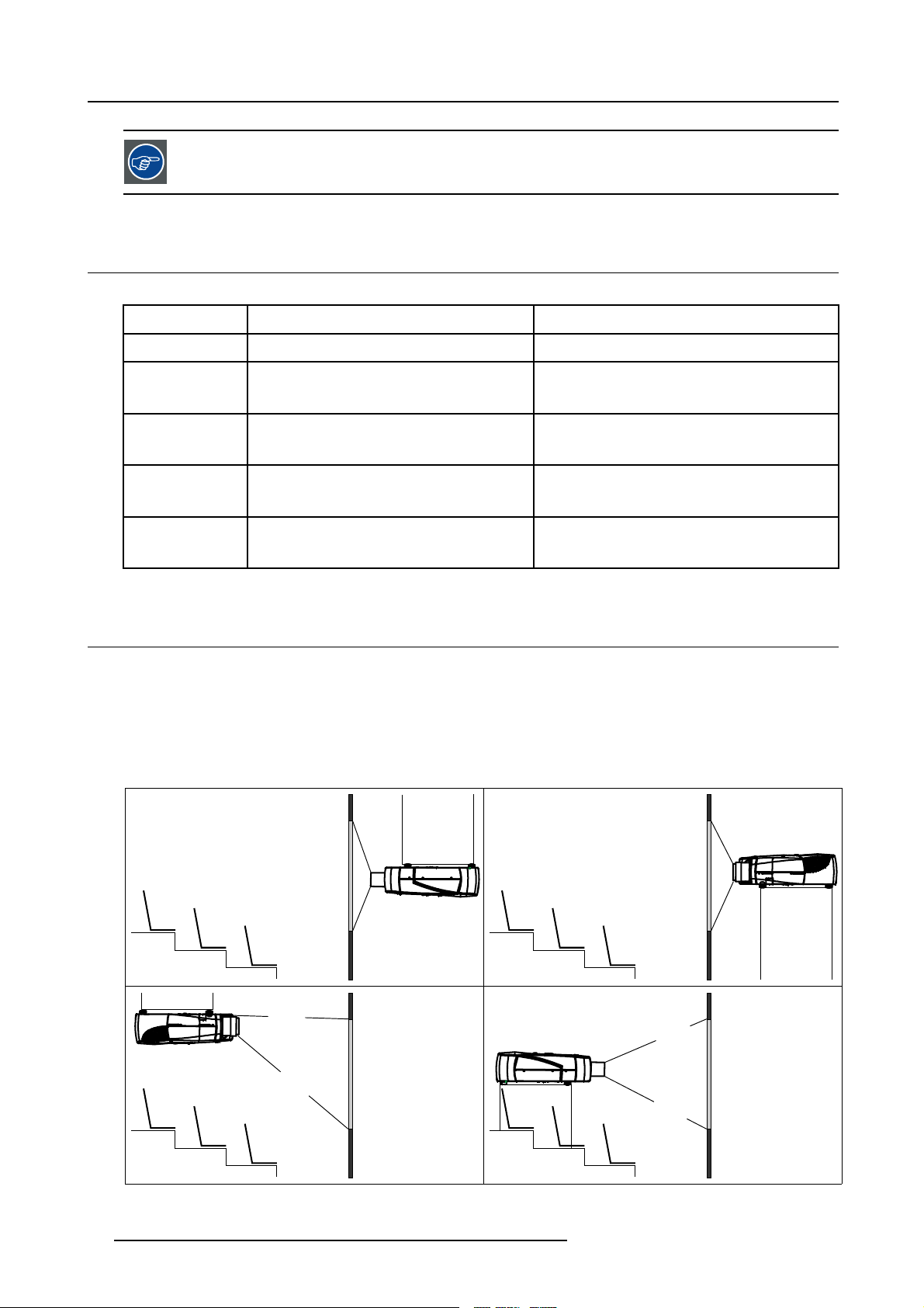
3.6 Projector configuration
The different configurations
Depending on the installation t
1. Rear/Ceiling
2. Rear/Table
3. Front/Ceiling
4. Front/Table
he projector can be mounted in different ways, the 4 different configurations are:
1
3
Image 3-6
2
4
10 R59770079 BARCO ID H250/500 11/05/2007
Page 15

3. Installation
The configuration should also be communicated to the projector. This is done in the Installationmenu through
the Projector Configuration parameter. (See Setup section)
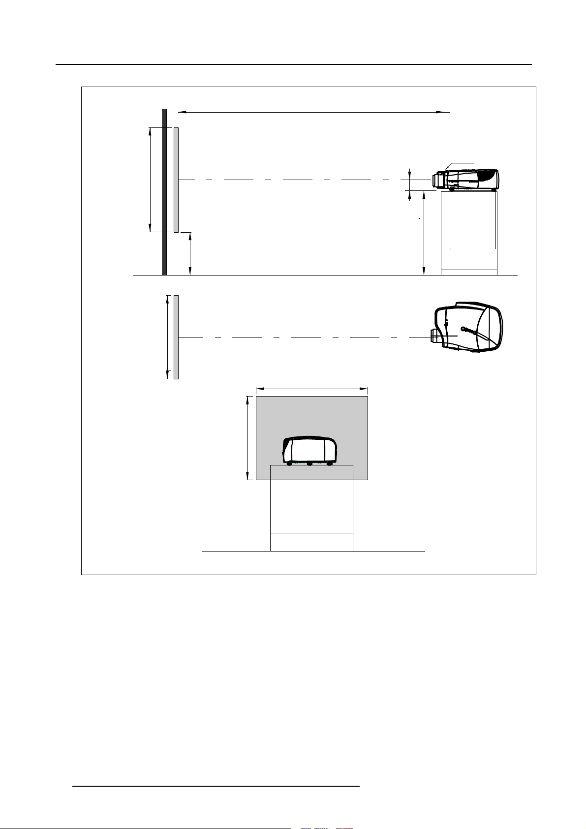
3.7 Positioning the projector
On-Axis projection
Projection where the projector is positioned so as to have the centre of the lens coinciding with the centre of the screen.
Positioning the projector
The position of the projector with reference to the screen may also be different depending on the installa
can be positioned in an On-Axis or Off-Axis configuration. Several parameters can be calculated determining the position in any
installation.
tion. Basically the projector
R59770079 BARCO ID H250/500 11/05/2007
11
Page 16
3. Installation
a
SH
PD
P
front plate
x
A
S
CD=SH/2+B-A
B
F
b
SW
S
SW
c
SH
F
Image 3-7
12 R59770079 BARCO ID H250/500 11/05/2007
Page 17
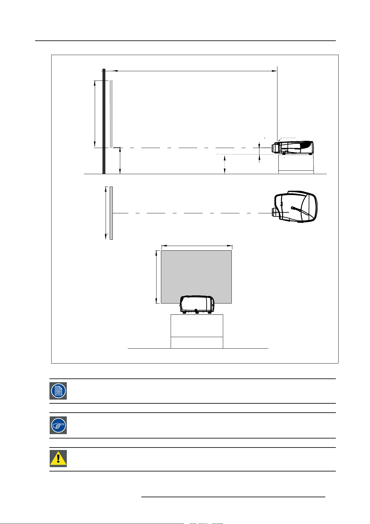
PD
3. Installation
a
b
c
SH
SW
front plate
S
A
B
S
SH
CD=B-A
F
SW
P
F
Image 3-8
A 10 0% Off-Axis position means that the position of the centre of the lens is shifted by half the screen height.
Never use a short throw lens in an Off-Axis installation. Shifting the lens will not guarantee optimal image
quality.
CAUTION: Only for projectors containing a Server (Single Board Computer) : The harddisk in the server is
formatted in horizontal position but ca n operate in all axes (6 directions). The projector should not be tilted
more then +/- 5 degrees from these positions, otherwise error rates will increase.
R59770079 BARCO ID H250/500 11/05/2007 13
Page 18
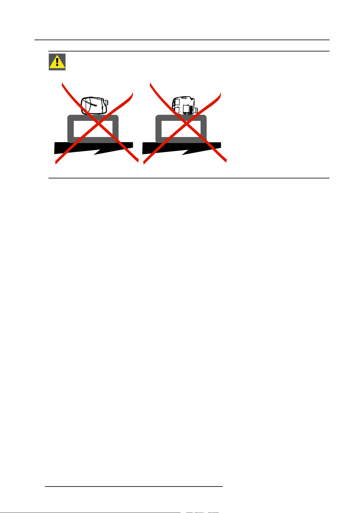
3. Installation
CAUTION: Never place the projector on either side !
Floor
Image 3-9
Floor
14 R59770079 BARCO ID H250/500 11/05/2007
Page 19
4. CONNECTIONS
Overview
• Power connection
• Signal connections
• Communication connections
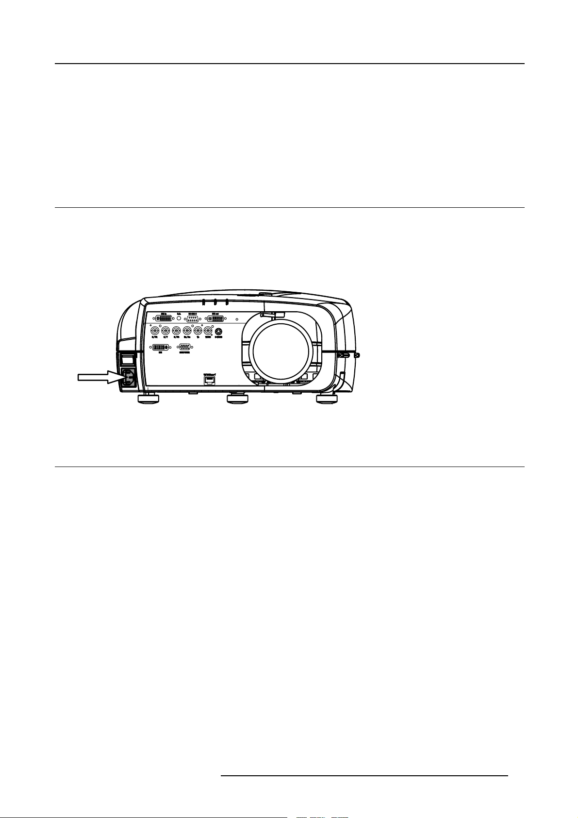
4.1 Power connection
Power connection
1. Use the supplied power cord to connect the projector to the power outlet.
2. Plug the female power connector into the male connector at the front of the projector. (image 4-1)
4. Connections
Image 4-1
Power connections
4.2 Signal connections
Overview
• The input section
• Connecting a Composite video signal
• Connecting an S-Video signal
• Connecting an RGB signal
• Connecting a Component Video signal
• Connecting a DVI signal
• Connecting a computer signal
• The DVI output
4.2.1 The input section
Input layers
The input section is located at the front of the projector and is composed of 3 layers which can be equipped with different input
modules depending on the ordered options .
The standard layers :
• Layer 1: DVI Input/Output module:
• Layer 2: RGBHV & Video analog input module
• Layer 3: DVI & Computer (D15) input module
• Layer 4 : Ethernet card
The different available options :
R59770079 BARCO ID H250/500 11/05/2007
15
Page 20
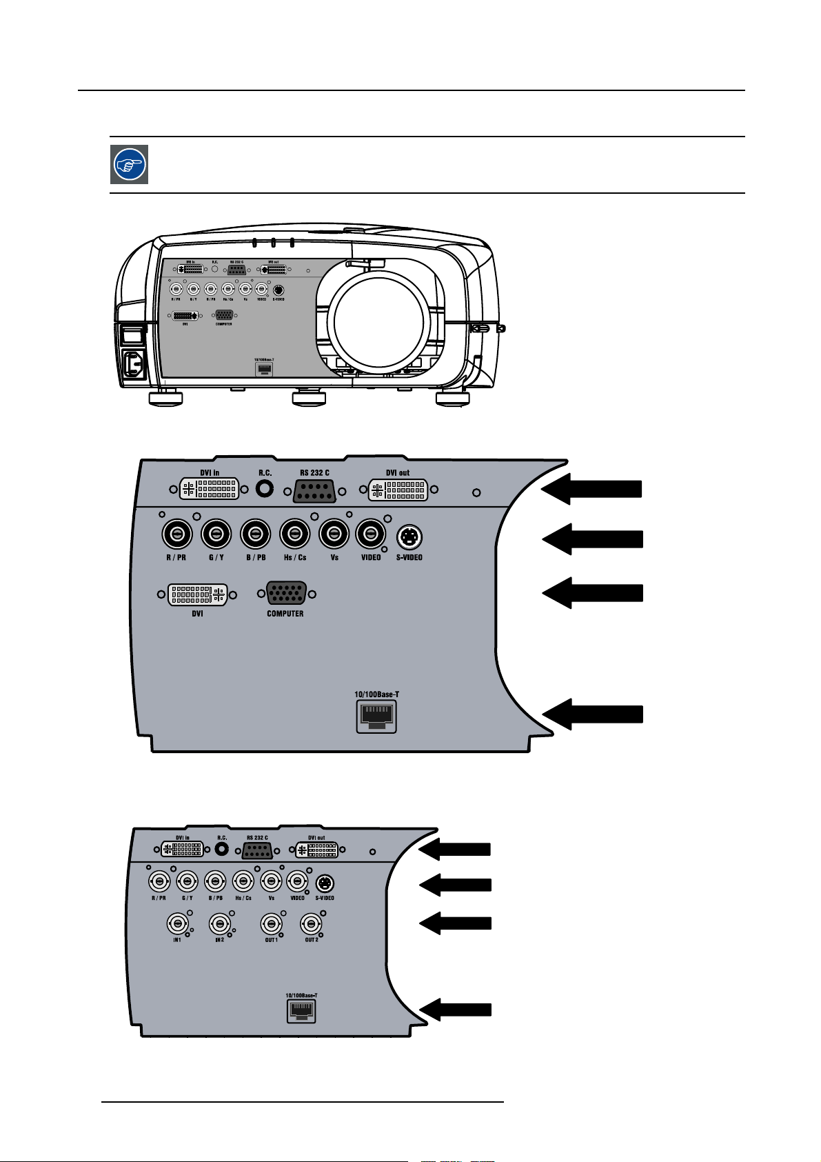
4. Connections
• HD SDI/SDI input output input module on Layer 3
When using the HD SDI option, t here is always a possibility to connect a VGA sig nal on the RGBHV input
using an adapter.
Image 4-2
Image 4-3
Input section
L1
LAYER 1
L1
LAYER 2
L1
LAYER 1
L1
LAYER 2
L1
LAYER 3
L1
LAYER 4
L1
LAYER 3
L1
LAYER 4
Image 4-4
Input with HDSDI/SDI module (ordered with HDSDI/SDI option)
16 R59770079 BARCO ID H250/500 11/05/2007
Page 21
4. Connections
r
r
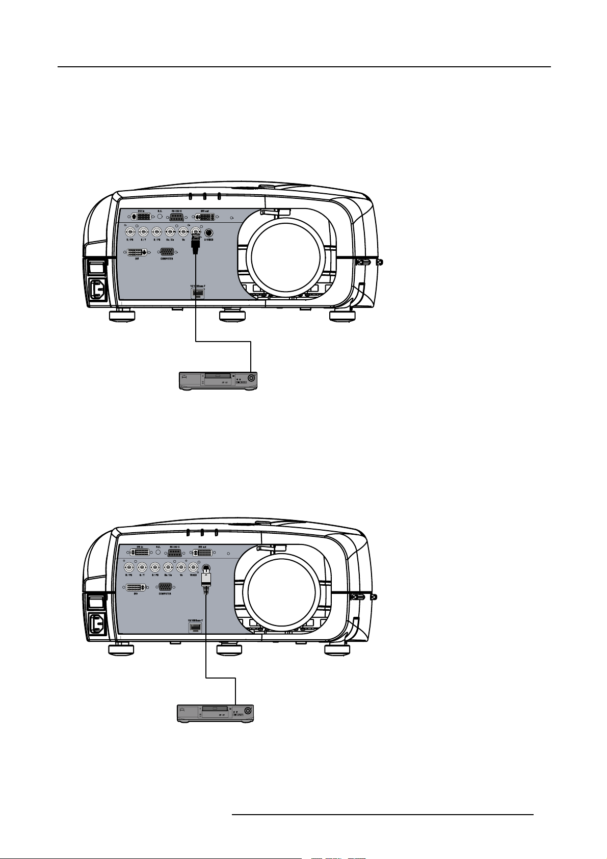
4.2.2 Connecting a Composite video signal
Composite video connection
A Composite video signal is often available on a yellow cinch connector of a Camera, VCR or DVD player, in this case you will need
an adapter cable cinch/BNC to connect to Video input of the RGB board.
How to connect a composite video signal ?
1. Connect the BNC connector to the projector’s BNC video input (image 4-5)
Image 4-5
DVD Playe
4.2.3 Connecting an S-Video signal
S-Video connection
An S-Video signal is available on the Mini-Din connector of a camera, VCR or DVD player.
How to connect an S-Video connection ?
1. Connect the mini din connector to the projector’s S-Video input (image 4-6)
Image 4-6
DVD Playe
R59770079 BARCO ID H250/500 11/05/2007 17
Page 22
4. Connections
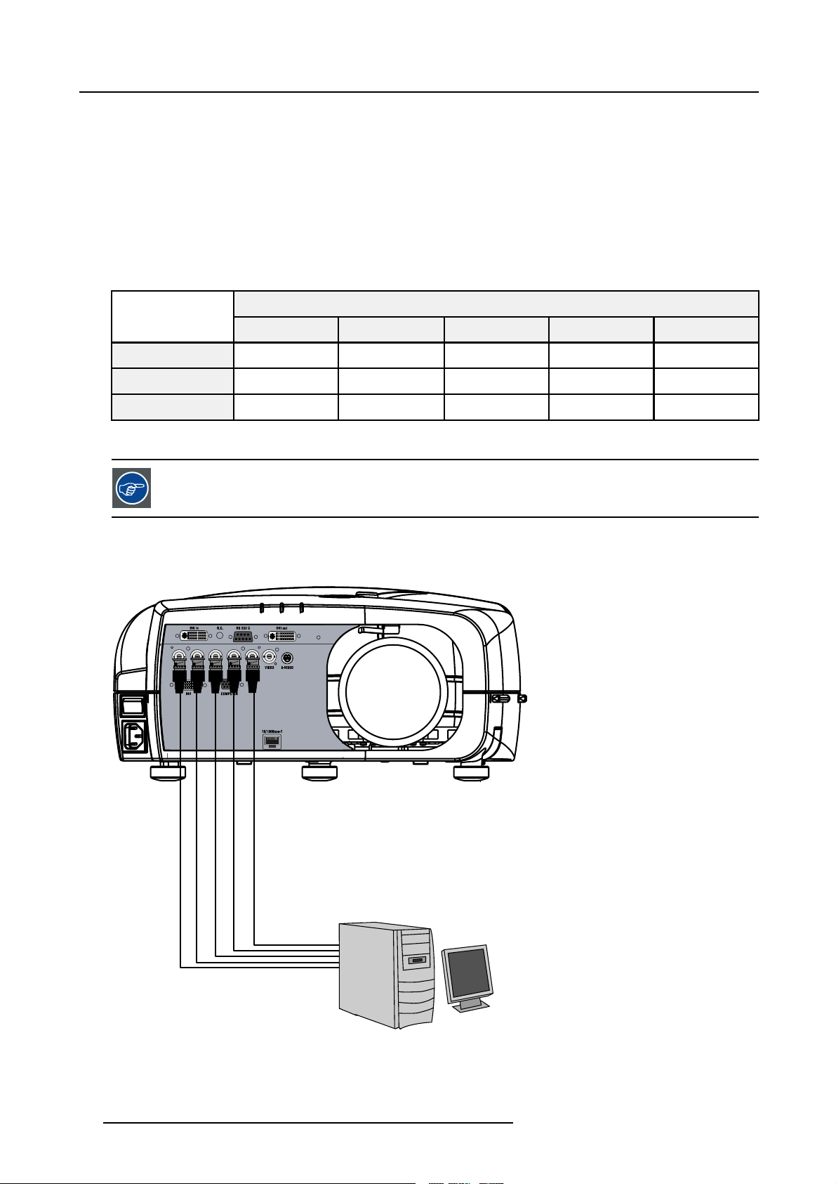
4.2.4 Connecting an RGB signal
RGB data connection
The RGB input consists of 5 BNC
• 3 for the color signals R,G,B
• 2 for the sync signals H (horizontal sync), V (vertical sync)
RGBS : If the source disposes of a composite sync output i.e. one wire includes the horizontal and the vertical sync than the V BNC
must not be connected, resulting in 4 BNC being connected (V is free).
RG
B : If the source disposes of a sync on Green output i.e. the Green color signal includes the horizontal and the vertical sync
s
than the H and V BNC’s must not be connected, resulting in 3 BNC being connected (H and V are free).
BNC Connector
R
RGBHV
RGsB
RGBS
Table 4-1
HowtousetheBNC’sincaseofdifferentRGBsignals
R
R
R
G
G
G
s
G
The RGB 5 BNC input can also be used to connect a component video source : see Connecting a Component
video source.
How to connect an RGB signal ?
1. Connect the 5 or 4 BNC cables to the projector’s RGB input (image 4-7)
B H V
B H V
B
B
- -
S
-
Image 4-7
18 R59770079 BARCO ID H250/500 11/05/2007
Page 23
4.2.5 Connecting a Component Video signal
r
Component Video
In Component Video the term component describes a number (3) of elements that are needed to make up the video
picture, these components are R-Y/Y/B-Y. A composite video signal on the other hand contains all the information
needed for the color picture in a single channel of information
How to connect a Component video signal ?
1. Connect the 3 BNC connectors to the projector’s RGB input (image 4-8)
4. Connections
Image 4-8
In case of a “progressive scan” compone nt video source, the notation used is PR/Y/PB
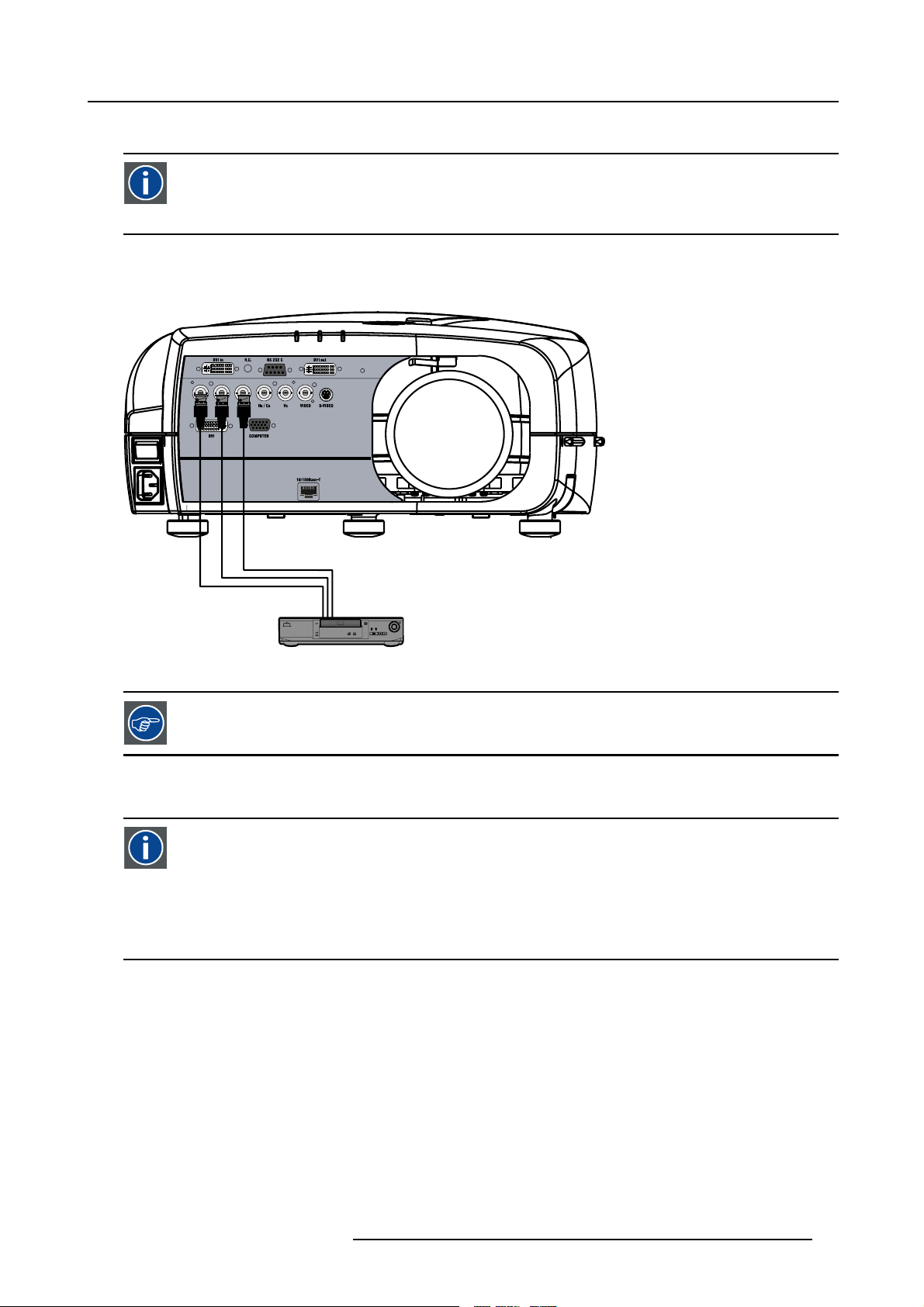
4.2.6 Connecting a DVI signal
DVI
Digital Visual Interface is a display interface developed in response to the proliferation of digital flat panel displays.
The digital video connectivity standard that was developed by DDWG (Digital Display Work Group). This connection
standard offers two different connectors: one with 24 pins that handles digital video signals only, and one with 29 pins
that handles both digital and analog video. This standard uses TMDS (Transition Minimized Differential Signal) from
Silicon Image and DDC (Display Data Channel) from VESA (Video Electronics Standards Association).
DVI can be single or dual link.
Input specifications
Single link DVI
Differential input voltage: 200 mV - 800mV
How to connect a DVI signal ?
1. Connect the DVI cable to the DVI input on L
DVD Playe
ayer 0 or on Layer 2 (image 4-9)
R59770079 BARCO ID H250/500 11/05/2007
19
Page 24
4. Connections
Image 4-9
Note that the 2 DVI outputs are identical an d are processed in the same way in the projector
4.2.7 Connecting a computer signal
How to connect a computer signal ?
1. Connect the D15 connector to the projector’s Computer input (image 4-10)
Image 4-10
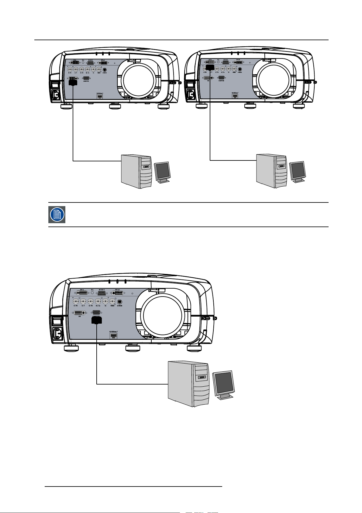
4.2.8 The DVI output
What can be done ?
The DVI output is a copy of the displayed image (without the OSD menu) and can be connected to an external monitor. Some
monitors can fail to synchronize on the DVI signal, in this case disable the Full screen synchronous representation function in the
Display Settings menu.
20
R59770079 BARCO ID H250/500 11/05/2007
Page 25
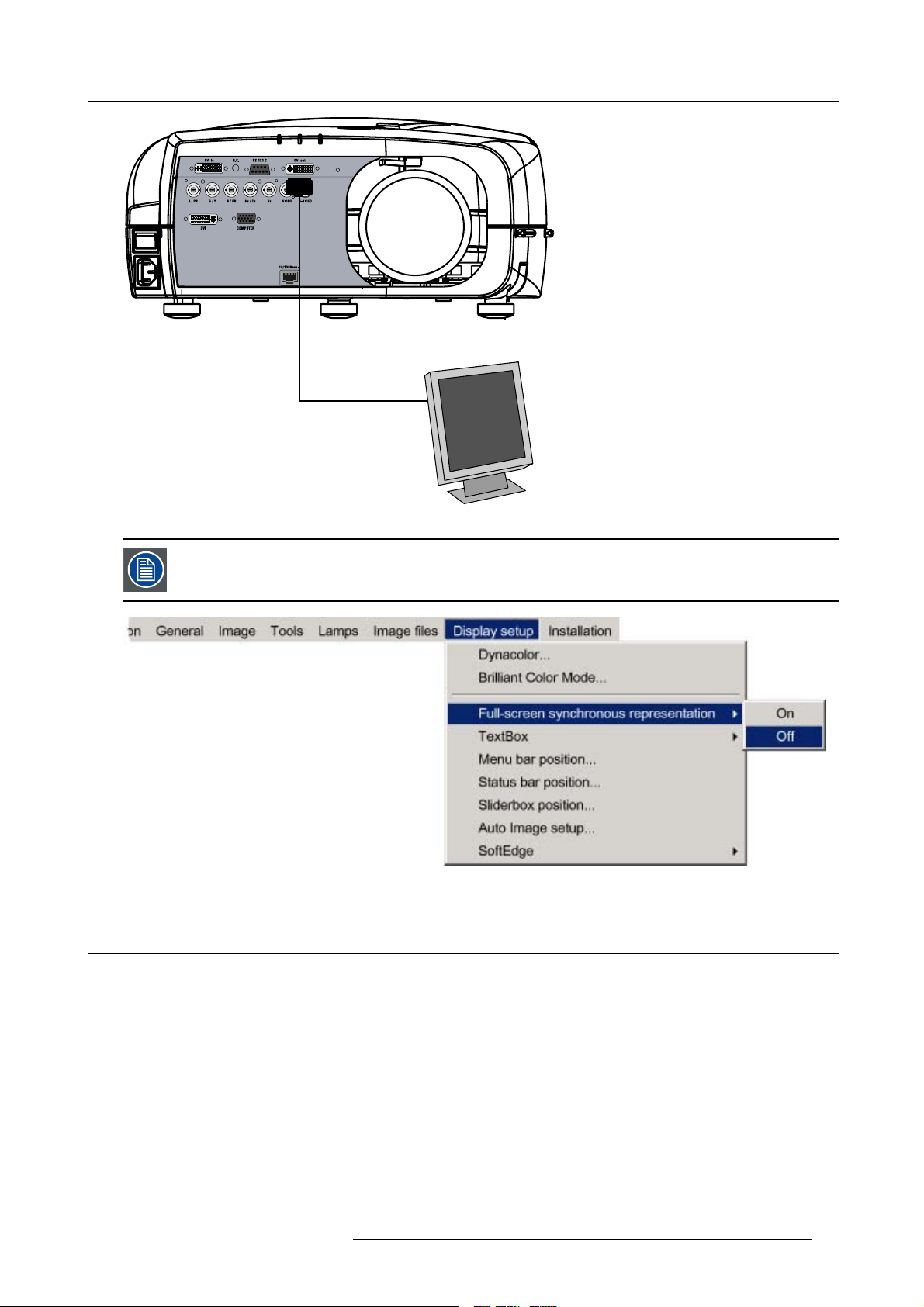
Image 4-11
4. Connections
The DVI output is at 1920x1080 (projector’s native resolution)
Image 4-12
4.3 Communication connections
Overview
• RS232/RS422 Connections
• Ethernet Connections
R59770079 BARCO ID H250/500 11/05/2007
21
Page 26
4. Connections
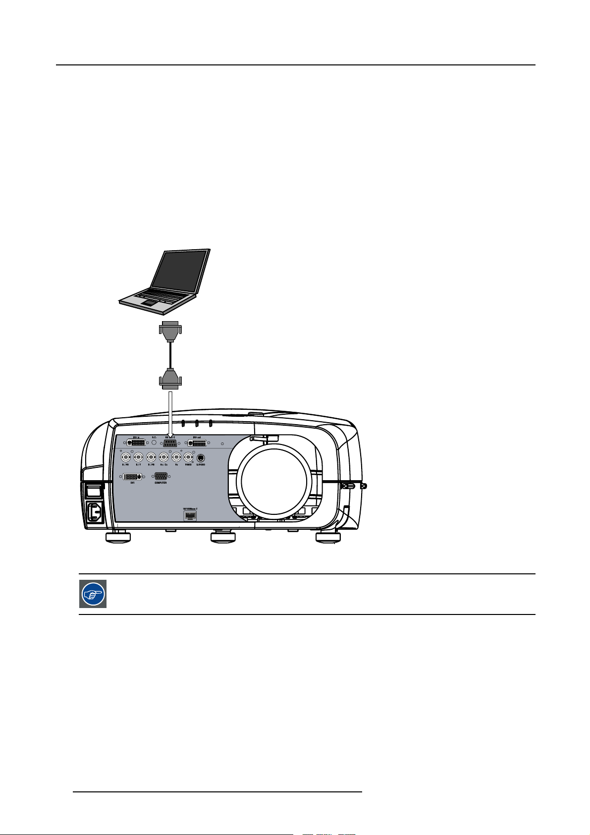
4.3.1 RS232/RS422 Connections
What is possible with the RS232/RS422 Connections?
1. Remote control :
- easy adjustment of projector when connected to an IBM PC (or compatible) or Apple computer.
- allow storage of multiple projector configurations and set ups.
- wide range of control possibilities.
- address range from 0 to 255.
2. Data communications: sending data to the projector or copying the data from the projector to a memory device (hard disc,
floppy, etc.).
How to connect the RS232/RS422 ports?
1. Connect the D9 connector from the RS232/RS422 cable to the RS Input on the projector. (image 4-13)
2. When applicable connect the RS232/RS422 Output to the next projector in the daisy chain setup.
PC Serial Port
Image 4-13
RS232 connection
See the Setup section for the baudrate and address
setting
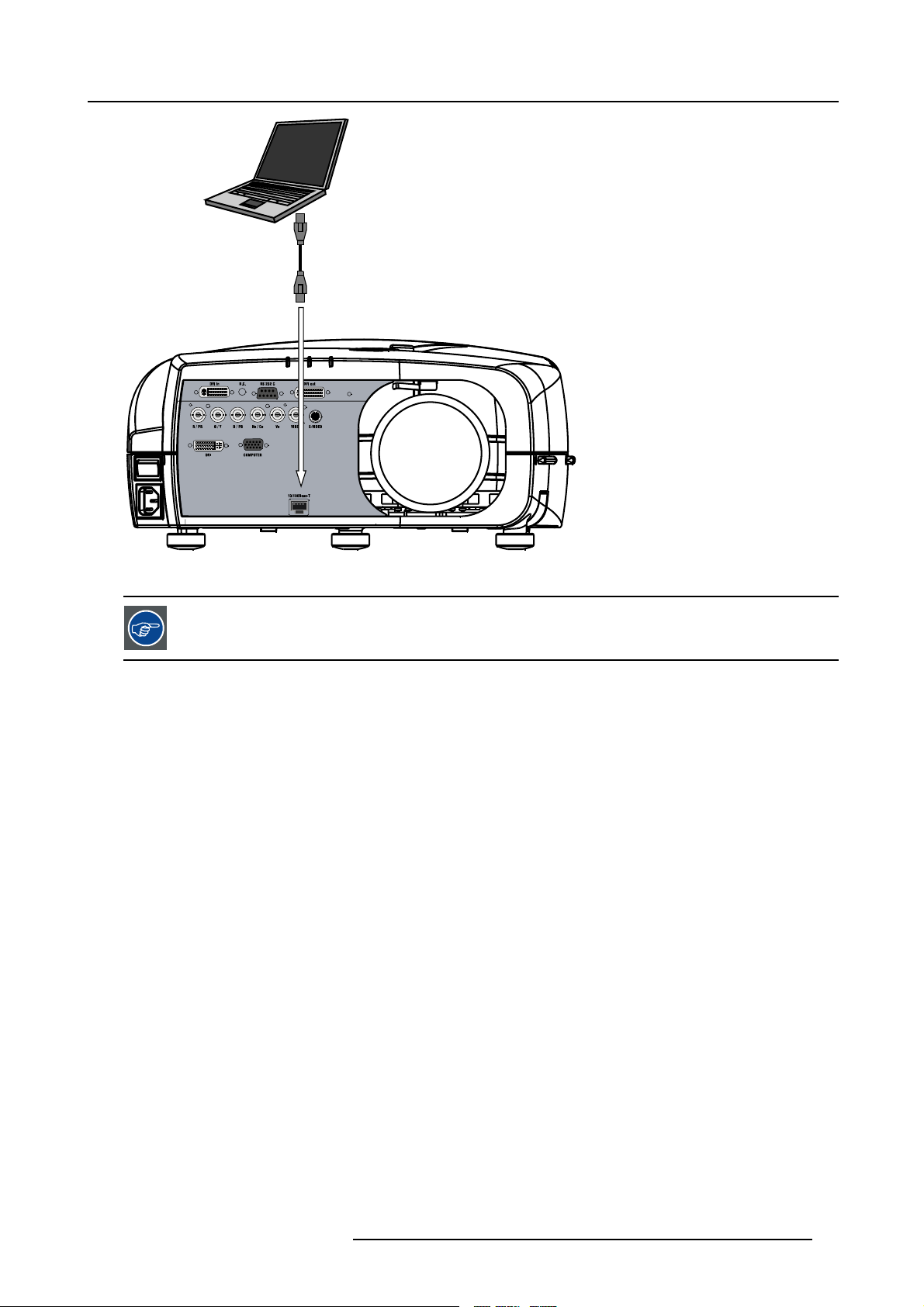
4.3.2 Ethernet Connections
What is possible with the Ethernet Connections?
The Ethernet Connections can be used to:
• Upload or download projector software.
• Set up RS232 communication (TCP-packets) with the projector.
How to connect the Ethernet ports?
1. Plug one end of the TCP/IP cable into the PC or the network socket. (image 4-14)
2. Connect the other end of the TCP/IP cable into the ’10/100Base-T’ port on the projector.
The orange led will light up when network ac
22
tivity is detected.
R59770079 BARCO ID H250/500 11/05/2007
Page 27
10/100 Base-T
4. Connections
Image 4-14
Ethernet connection
See the Setup section for the network setting
R59770079 BARCO ID H250/500 11/05/2007 23
Page 28

4. Connections
24 R59770079 BARCO ID H250/500 11/05/2007
Page 29

5. SETUP
Overview
• RCU & Local keypad
• Terminology overview
• Switching on
• Setting up the RCU address
• Setting up the projector address (only if necessary)
• Setting up the orientation
• Adjusting the lens
• Setup the baudrate for serial communication
• Network settings
• Preferences
5.1 RCU & Local keypad
How controlling the projector ?
The projector can be controlled by the local keypad or by the remote control unit.
5. Setup
Location of the local keypad ?
The local keypad is located on the topside of the projector.
For key overview: "Terminology overview", page 27
R59770079 BARCO ID H250/500 11/05/2007
25
Page 30
5. Setup
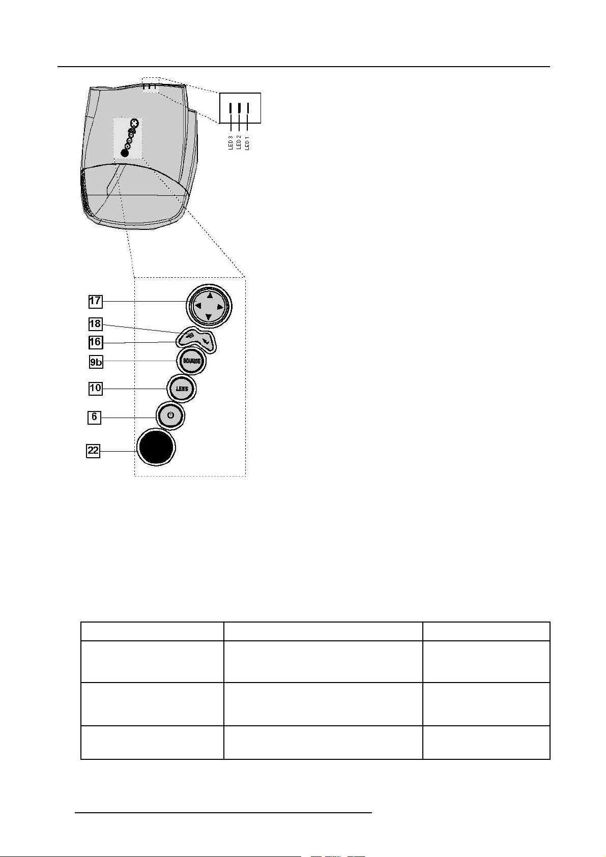
Image 5-1
Local keypad layout
Remote control functions.
This remote control includes a battery powered infrared (IR) transmitter that allows the user to control the projector remotely. This
remote control is used for source selection, control, adaptation and set up. It includes automatic storing of picture controls (Brightness, Sharpness...) and settings.
Other functions of the remote control are :
• switching between stand by and ope
• switching to "pause" (blanked picture, full power for immediate restarting)
• direct access to all connected sources.
rational mode.
Diagnose LED’s
Green
LED1
LED2
LED3 IR acknowledgement continue : standby
cool down sequence: flickers 60 seconds (120
seconds in case of iQ 400 series) after switching
to standby
only for the versions containing a server:
shows when projector is in
standby and server is active.
Red
rescue program (software error)
hardware error
flickers : Security = ON
26 R59770079 BARCO ID H250/500 11/05/2007
Page 31

5.2 Terminology overview
Overview
The following table gives an overview of the keys.
5. Setup
Image 5-2
1 Function keys
2 MENU Menu key, to enter or exit the Toolbar menu.
3 Address key
4
LOGO key allows to recall the stored Logo (not in PiP mode)
5
PAU SE to stop projection for a short time, press ’PAUSE’. The image disappears but full power is
6
STBY standby button, to start projector when the power switch is switched on and to switch off the
7
MUTE
8
AUTOIMAGE Auto image, to center the image on the active LCD surface.
9 Digit buttons direct input selection.
9b
SOURCE button this button allows to switch through the active (scanned) inputs
R59770079 BARCO ID H250/500 11/05/2007 27
user programmable keys with functions for direct access.
(recessed key), to enter the address of the projector (between 0 and 9). Press the recessed
address key with a pencil, followed by pressing one digit button between 0 and 9.
retained for immediate restarting.
projector without switching off the power switch.
Attention : Switching to Standby. When the projector is running and you want to
go to standby, press the standby
to interrupt the sound reproduction (audio = optional.
key for 2 seconds.
Page 32

5. Setup
10 Lens control
11
VOL use this button to obtain the desired sound level (audio = optional)
use these buttons to obtain the desired ZOOM, SHIFT, FOCUS.
12 Picture controls use these buttons to obtain the desired picture analog level.
13
DIGI ZOOM allows a digital Zoom of a part of the image
14 FREEZ
15 PIP
16 ENTER
press to freeze the projected image.
allows to activate the PICTURE IN PICTURE mode
to confirm an adjustment or selection in the MENU.
On the local keypad the ENTER button additionally accesses the PIP window resize function
17
Cursor keys Cursor Keys on RCU or on the local keypad : to make menu selections or to access the
toolbar.
18
BACK to leave the selected menu or item (go upwards to previous menu).
19
EFFECTS
20
PIP ADJUST allows to select a PiP window and change its configuration on screen
21
RC operating indication lights up when a button on the remote control is pressed. (This is a visual indicator to
not yet implemented
check the operation of the remote control)
22 IR receiver IR receiver
Table 5-2
ordernumber RCU: R763794K
Depending on the projectors some functions
5.3 Switching on
How to switch on.
1. Press the power switch to switch
- When ’0’ is pushed in, the projector is switched off.
- When ’1’ is pushed in, the projector is switched on
The projector starts in standby mode, LED3 is red.
Starting image projection.
1. Press Standby key once on the local k
MEN U BACK
like LOGO,DIGI ZOOM, PiP, ... are not supported.
on the projector.
eypad or on the remote control. (image 5-3)
EN T ER
PA U
9
Image 5-3
PI P
SE
L
OGO
DIGI
Z
M
OO
0
PH A
SE
28 R59770079 BARCO ID H250/500 11/05/2007
Page 33

It may take about 60 seconds before image projection, i.e. no projection until the completion of s everal operations (software initialization,...).
If the Security mode is enabled, a textbox will be displayed for PIN code entry, see Security settinginthe
Installation menu
5.4 Setting up the RCU address
What has to be done ?
To allow the communication between the RCU and the projector the RCU has to be programmed with the same address as the
projector.
This address must be in the range 0–9.
To know the address of the projector, one can visualize it in projection mode (on screen) as well as in
the LED’s on top cover of the projector).
For more info on addresses see the appendix
standby mode (shown with
5. Setup
At this stage the image projected may happen to be upside down or mirrored, this can be set in the Installation
menu under Projector orientation (see further setting up the projector’s orientation).
Displaying the Projector Address in Standby mode
1. Press the Address key (recessed key on the RCU) with a pencil. (image 5-4)
All the LED’s (3) on the top cover of the projector go out.
Then LED1 starts blinking green the number of hundreds. After that LED2 starts blinking the number of tens. Finally LED3 starts
blinking green the number of units. If this is done, the original status of the LED’s is restored.
MEN U BACK
EN T ER
PA U
9
Image 5-4
PI P
SE
L
OGO
DIGI
Z
M
OO
0
PH A
SE
Displaying the Projector Address in projection mode)
1. Press the Address key (recessed key on the RCU) with a pencil.
The projector’s address will be displayed on the screen in a Textbox
Programming the RCU
1. Push the address key If the address is not entered within 5 seconds, the RCU returns to its default address (zero address) and
controls then all projectors in the room
2. Enter the same address with the digit buttons within 5 seconds after pushing the address key.
The projector can now be controlled with the RCU.
R59770079 BARCO ID H250/500 11/05/2007
.
29
Page 34

5. Setup
For example : if the projector address is 3, then press "3" on the RCU to set the RCU’s address to match the
projector’s address.
Common address/Projecto r address : Beside the projector address, the projector disposes also of a Co mmon
address which can be set to “0” or “1” (by default “0”).
In other w ords, an R CU set to address “0” will always control a projector regardless of its projector address
(since it uses the common address).
5.5 Setting up the projector address (only if necessary)
What can be done ?
The projector is shipped with projector address set to ”0”
In some cases the projector address must be changed, for example if an unique RCU is used to control 2 o
pendently).
In the OSD menu Projector Address, the following addresses can be programmed :
• Projector address: address defined by the user, may be from 0 to 255
0-9 is used for RCU communication, 0–255 being used for RS232 serial communication.
• Common address : address may be 0 or 1
r more projectors (inde-
For more info on addresses see the appendix
How to change the projector’s address ?
1. Press MENU to activate the Tool bar
2. Press → to select the Installation
3. Press ↓ to Pull down the Installation menu
4. Use ↑ or ↓ to select Projector address (image 5-5)
5. Press ENTER
A dialog box appears on the screen (image 5-6)
6. Enter the new projector address with the digit keys on the RCU, the local keypad or the cursor keys.
Image 5-5
30 R59770079 BARCO ID H250/500 11/05/2007
Page 35

Image 5-6
How to change the common address ?
1. Proceed in the same way as for the projector address
5.6 Setting up the orientation
What must be done ?
Depending on the mechanical orientation of the projector, the projector’s internal settings have to be adapted.
The projector is shipped (default) with a table/front orientation.
How to set the orientation ?
1. Press MENU to activate the Tool bar
2. Press → to select the Installation item
3. Press ↓ to Pull down the Installation menu
4. Use ↑ or ↓ to select Orientatio
5. Press → to pull down the menu
6. Use ↓ or ↑ to select the desired orientation (image 5-7)
7. Press ENTER
The projection is adapted and a bullet shows the active configuration.
n
5. Setup
Image 5-7
5.7 Adjusting the lens
What must be done ?
Depending on the projection distance and the lens used, the image may not be at the desired size, position and/or may be out of
.
focus
The projector will always allow you to shift your image vertically as well as horizontally (when available) to position it on the screen.
In addition, motorized lenses will also allow you to Zoom and focus the image.
All these lens parameters can be adjusted using the RCU, the local keypad or in the Installation menu of the projector’s OSD.
R59770079 BARCO ID H250/500 11/05/2007
31
Page 36

5. Setup
• Zoom (only for motorized lenses)
• Focus (only for motorized lenses)
• Vertical Shift
The lens can also be adjusted via the dedicated keys on the remote.
How to Zoom/focus or shift via the RCU (or keypad)
1. Press LENS ZOOM or
LENS FOCUS or LENS SHIFT on the RCU (image 5-8)
2. Use the arrow keys to adjust (image 5-9)
4
3
BRIGHTN
2
1
Image 5-8
LENS
ZOOM
LENS
FOCUS VOL
CONTR
LENS
SH IF T
Image 5-9
MEN U BACK
PA U
9
PI P
SE
L
OGO
DIGI
Z
M
OO
0
PH A
SE
EN T ER
How to Zoom/focus or shift in the OSD ?
1. Press MENU to activate the Tool bar
2. Press → to select the Installation
3. Press ↓ to Pull down the Installation menu
4. Use ↑ or ↓ to select Lens Adjustments... (image 5-10)
5. Press ENTER
A text box appears on the screen, follow the instructions. (image 5-11, image 5-12)
Image 5-10
32 R59770079 BARCO ID H250/500 11/05/2007
Page 37

Image 5-11 Image 5-12
The use of a sheet of paper held in front o f the screen can be useful to determine the focus plane (position
for best focus)
Vertical s hift range : -25% (do wn) to 140%(up)
Except for the QCLD (0.85:1) : -25%(down) to 30%(up)
5. Setup
5.8 Setup the baudrate for serial communication
What can be done ?
The RS232 IN port of the projector allows you to communicate with any other equipment disposing of an RS232 port (generally a
PC used to
projector and the other equipment.
How to change the baudrate?
1. Press MENU to activate the Tool bar
2. Press → to select the Installation item
3. Press ↓ to Pull down the Installation menu
4. Use ↑ or ↓ t
5. Press → to pull down the menu
6. Use ↓ or ↑ to select the desired baudrate
7. Press ENTER
upgrade the projector’s firmware) using the RS232 protocol. The baudrate must be set to the same value on both the
o select RS232 baudrate (image 5-13)
Image 5-13
R59770079 BARCO ID H250/500 11/05/2007 33
Page 38

5. Setup
Always select the highest rate (115200) unless otherwise specified.
5.9 Network settings
What can be done?
These settings are used to set the Ethernet Communication parameters.
The Ethernet connection can be used to upload/download projector software and/or to set up RS232 communication (TCP-pa
with the projector.
Following parameters are available :
ckets)
MAC Address MAC Address of the projector (This is a non-adjustable value programmed into the Ethernet
IP Address (Current) IP Address of the projector (This is a non-adjustable value ).
Subnet Mask Subnet Mask (This is a non-adjustable value )
Gateway Gateway (This is a non-adjustable value )
DHCP
IP Address
Subnet Mask Subnet Mask : this field can be edited when Fixed IP is selected
Gateway Gateway : this field can be edited when Fixed IP is selected
Hostname
board).
DHCP setting:
• Yes: The projector will dynamically obtain its IP address from the DHCP server.
• No: The IP address needs to be entered manually. Note that when selecting Fxed IP
the IP settings fields are enabled
Fixed IP Address of the projector : this field can be edited when Fixed IP is selected
Hostname : this field can be edited when DHCP is selected
How to set up the network settings ?
1. Press the MENU key to activate the Menu bar.
2. Push the cursor key ← or → to highli
3. Push the ↓ key to pull down the Installation menu.
4. Push the cursor key ↑ or ↓ to highlight Network settings and press ENTER to select. (image 5-14)
A dialog box will be displayed. (image 5-15)
5. Push the cursor key ↑ or ↓ to highlight the desired parameter.
6. Use the cursor key ← or → , the numeric keys on the RCU, or the local keypad, to edit and change the values.
7. Press Apply settings to apply the
A dialog box is shown. The different executed operations are shown with a checkbox. The last operation Restarting network
takes a few seconds more. (image 5-16)
ght Installation in the menu bar.
changes
34
R59770079 BARCO ID H250/500 11/05/2007
Page 39

Image 5-14
5. Setup
Image 5-16
Image 5-15
5.10 Preferences
Overview
• Language setting
• Automatic startup
5.10.1 Language setting
List of languages
The list of selectable languages depends on the software version of the projector.
How to change the Language ?
1. Press MENU to activate the Tool bar
R59770079 BARCO ID H250/500 11/05/2007
35
Page 40

5. Setup
2. Press → to select the Installation item
3. Press ↓ to Pull down the Installation menu
4. Use ↑ or ↓ to select Language
5. Press → to pull down the menu
6. Use ↓ or ↑ to select the desired language (image 5-17)
7. Press ENTER
The language is adapted and a bullet shows the active selection.
Image 5-17
5.10.2 Automatic startup
What can be done ?
The automatic startup allows to bypass the standby state i.e. start up without going in standby state after switching on the projector.
This means that the automatic startup allows immediate restart of the projector after a power failure (breakdown), i.e. without passing
through the standby state, by recovering the previous setti
This function can be disabled if undesired or inadequate for safety reasons, etc.
ngs (previous source,...).
CAUTION: If the Automatic startup function is enabled one must be aware of the fact that it involves safety
precautions
Make sure that the projector (or the operators!) will not be affected by altered environmental conditions when
restarting at power resume.
Unless it is required, it is advised to leave this setting OFF.
In case of a power breakdow n, this may introduce unwant
up with high lamp temperature conditions, bad PC status, ...
ed conditions at power resume : projector starting
How to enable/disable the Automatic startup?
1. Press MENU to activate the Tool bar
2. Press → to select the Installation item
3. Press ↓ to Pull down the Installation menu
4. Use ↑ or ↓ to select Automatic startup
5. Press → to pull down the menu
6. Use ↓ or ↑ to enable/disable the automatic startup (image 5-18)
7. Press ENTER
36
R59770079 BARCO ID H250/500 11/05/2007
Page 41

Image 5-18
5. Setup
R59770079 BARCO ID H250/500 11/05/2007 37
Page 42

5. Setup
38 R59770079 BARCO ID H250/500 11/05/2007
Page 43

6. GETTING STARTED
Overview
•Startup
• Selecting a source
• Adjusting the image
6.1 Start up
How to start up the pro je ctor ?
1. Press the Standby button on the RCU or the local keypad (image 6-1)
The last selected source is displayed
MEN U BACK
EN T ER
PA U
9
Image 6-1
PI P
SE
L
OGO
DIGI
Z
M
OO
0
PH A
SE
6. Getting started
6.2 Selecting a source
How to select a source ?
1. Press the digit, corresponding to the desired source, on the remote control .
6.3 Adjusting the image
How to adjust the image ?
1. Use the Image setting buttons on the RCU (image 6-2)
PH A
SE
TINT
COLO
R
BRIGHTN
CO
NTR
Image 6-2
R59770079 BARCO ID H250/500 11/05/2007 39
Page 44

6. Getting started
40 R59770079 BARCO ID H250/500 11/05/2007
Page 45

7. ADVANCED
Note that the Installation menu is handled in the Installation chapter and the Tools menu is handled in the
Troubleshooting section.
Overview
• The OSD Menu
• Using the Dialog boxes
• Source selection
• General
• Image
• Lamp management
• Image files
• Display setup
7.1 The OSD Menu
Structure
The projector has a build in tool bar menu which allows easy access to different parameters for projector setup.
The menu is activated by pressing MENU, it contains 2 levels depending on the type of user:
7. Advanced
• Level 1: Standard user
• Level 2: Advanced user
Level 2 is password protected, the advanced parameters are only visible when the correct password has been entered ( factory
password = "0000")
When the advanced parameters are not visible the y are replaced by “More ...”
Menu items which are not applicable are greyed out.
Menu Layout
A grey line gives the transition between standard and advanced parameters.
The existence of a submenu is indicated by a white arrow.
Three suspension points indicate that the menu item hides a dialog box or a te
The menus inserted in this manual are of the advanced type: all the it
standard user on the screen will hence not correspond with the menus in the manual i.e. the advanced items
will not be visible, they will be replaced with "More..."
Greyed out menus or items are not available in this software version
xt box.
emsarevisibleThemenusseenbya
How to pull down a menu ?
1. Use ↓ to pull down a menu
How to pull down a submenu ?
1. Use → to pull down a submenu
How to exit the submenu ?
1. Press BACK to exit a submenu
Press MENU to exit the menu
R59770079 BARCO ID H250/500 11/05/2007 41
Page 46

7. Advanced
When the menu has been exited for more than 1 minute, the advanced user password has to be re entered.
7.2 Using the Dialog boxes
How to use the dialog boxes ?
Some parameters are modified by means of a dialog box, where selections can be made and/or values can be entered.
The values can be entered in several ways:
Entering numeric values using the numeric keys on the remote control
1. Press ENTER to activate the input field. (image 7-1)
2. Key in the desired value.
Image 7-1
Entering numeric values using the arrow keys on the remote control
1. Press ENTER to activate the input field.
2. Press ← or → to select the digit to be changed. (image 7-2)
3. Press ↓ or ↑ to increase or decrease the value.
Image 7-2
Entering numeric values using the arrow keys on the local keypad
1. Press ENTER to activate the input field.
2. Press ← or → to select the digit to be changed.
3. Press ↓ or ↑ to increase or decrease the value.
To confirm the changes always press ENTER.
Use ↓ or ↑ to browse between the different fields.
In some cases an alphanumeric value (file name, ...) has to be entered. Use ↑ or ↓ to scroll through the character values once the input field is activated.
Following characters can be browsed in this particular order:
Decimal scroll list: 0123456789
Signed decimal scroll list: 0123456789-
ASCII scrolllist:ABCDEFGHIJKLMNOPQRSTUVWXYZ0123456789+-*/&@#.;.abcdefghijklmnopqrstuvwxyz
42 R59770079 BARCO ID H250/500 11/05/2007
Page 47

7. Advanced
7.3 Source selection
Overview
• Source selection
• Composite video
•S-Video
•RGB-YUV
•PC
•DVI
7.3.1 Source selection
Selecting a source
The Source selection menu allows to select one of the different inputs. Another method to select an input source is via the remote
control using the numeric keys or by using the local keypad.
Selecting a source from the menu bar (OSD) will always display that source in a full screen mode.
When selecting a source with a different resolution (and/or aspect ratio) th an the projector’s resolution (and/or
aspect ratio ), the so urce can be shown in its native reso lution or can be re-scaled to the projector’s resolution
thelattercasebringsofcoursesomelostofquality.
The resolution of the projector is 1920x1080 with an aspect ratio of 16:9
Selecting a source via the local keypad : the Source b utton on the local keyp ad allows to access the Source
selection menu, continue with the arrow buttons and the ENTER button to select a s
7.3.2 Composite video
When
Select composite video when you are in presence of a PAL or NTSC video signal.
A composite video signal is often available on a yellow cinch connector
How to select the composite video input ?
1. Press MENU to activate the Tool bar
2. Press ↓ to Pull down the Source Selection menu
3. Use ↑ or ↓ to select L2 Video (image 7-3)
4. Press ENTER to confirm your choice
A bullet indicates the selected composite video source which now appears on the screen.
,
ource via the local Keypad
of a Camera, VCR or DVD player.
Image 7-3
R59770079 BARCO ID H250/500 11/05/2007 43
Page 48

7. Advanced
Adjustments on a Composite video signal
The projectors allows different adjustments on a composite video signal. Depending on the type of signal (NTSC /PAL) the terminology may differ :
• Contrast
• Brightness
• Color : adjusts the level of color saturation in a PAL signal
• Tint : adjusts the level of color saturation in an NTSC signal
• AGC: Automatic Gain Control
7.3.3 S-Video
When
Select the S-Video input when in presence of a video signal also called S-VHS signal.
An S-Video signal is available on the Mini-Din connector of a camera, VCR or DVD player.
AdjustmentsonaS-Videosignal
The projectors allows different adjustment on a video signal. Depending on the type of signal (NTSC /PAL) the terms differ :
• Color : adjusts the level of color saturation in a PAL signal
• Tint : adjusts the level of color saturation in an NTSC signal
How to select the S-Video input ?
1. Press MENU to activate the Tool bar
2. Press ↓ to Pull down the Source Selection menu
3. Use ↑ or ↓ to select L2 S-Video (image 7-4)
4. Press ENTER to confirm your choice
A bullet indicates the selected composite video source which now appears on the screen.
Image 7-4
7.3.4 RGB-YUV
When
Select RGB-YUV when in presence of a data signal of the type RGB+
signal of the type (R-Y)/Y/(B-Y). The submenu of RGB-YUV allows to select whether it is an RGB signal or a component signal YUV.
These signals are often available on a VGA D15 connector of a PC or another image generator.
An RGB data signal can have its sync signal added in different ways, refer to the Installation section for more
information on the RG B +syn c signals accepted by the RGB in pu t.
sync connected to the RGB input (5 BNC’s) or a component
How to select the RGB input ?
1. Press MENU to activate the Tool bar
2. Press ↓ to Pull down the Source Selection menu
3. Use ↑ or ↓ to select L2 RGB-YUV
4. Use → to open the menu
44
R59770079 BARCO ID H250/500 11/05/2007
Page 49

5. Use ↑ or ↓ to select RGB or YUV (image 7-5)
6. Press ENTER to confirm your choice
A bullet indicates the selected source which now appears on the screen.
Image 7-5
AdjustmentsonanRGBsignal
The projector allows different adjustments on an RGB signal :
• Contrast
• Brightness
• Phase
• Input balance
• AutoImage : or manual edit of the image file settings
7. Advanced
7.3.5 PC
When
Select PC when you are in presence of a data signal of the RGB + sync form connected to the D15 input connector of the projector.
An RGB data signal can have its sync signal added in different ways, refer to the Installation section for more
information on the RGB+sync signals accepted by the PC input.
How to select the PC input ?
1. Press MENU to activate the Tool bar
2. Press ↓ to Pull down the Source Selection menu
3. Use ↑ or ↓ to select L3 PC (image 7-6)
4. Press ENTER to confirm your choice
A bullet indicates the selected composite video source which now appears on the screen.
Image 7-6
7.3.6 DVI
When
The projector is equipped with 2 DVI inputs, one located on the layer 1 and the other on layer 3.
R59770079 BARCO ID H250/500 11/05/2007
45
Page 50

7. Advanced
Select DVI when in presence of digital data signal connected to a DVI input of the projector. These signals are often available on a
PC or other image generator.
How to select the DVI input on layer 1 ?
1. Press MENU to activate the Tool bar
2. Press ↓ to Pull down the Source Selection menu
3. Use ↑ or ↓ to select L1 DVI (image 7-7)
4. Press ENTER to confirm your choice
A bullet indicates the selected composite video source which now appears on the screen.
Image 7-7
How to select the DVI input on layer 3?
1. Press MENU to activate the Tool bar
2. Press ↓ to Pull down the Source Selection menu
3. Use ↑ or ↓ to select L3 DVI (image 7-8)
4. Press ENTER to confirm your choice
A bullet indicates the selected composite video source which now appears on the screen.
Image 7-8
Adjustments on a DVI signal
The digital nature of this signal eliminates the need of a large number of adjustments
7.4 General
Overview
• Pause
• Freeze
• Identification
46
R59770079 BARCO ID H250/500 11/05/2007
Page 51

7. Advanced
7.4.1 Pause
Pause
The Pause function allows to stop the image display, the projector remaining with full power for immediate restart. The image display
is interrupted and the projected background is black.
How to pause the image display?
1. Press MENU to activate the Tool bar
2. Press → to select General
3. Press ↓ to Pull down the General menu
4. Use ↑ or ↓ to select Pause (image 7-9)
5. Press ENTER
Image 7-9
The projection can also be interrupted using the PAUSE key on the RCU. To restart the image pr
PAUSE
ojection press
7.4.2 Freeze
Freezing the image
With the Freeze function, the image can be frozen. To restart the image, reuse the Freeze function or press the FREEZE button on
the remote.
Howtofreezetheimage?
1. Press MENU to activate the Tool bar
2. Press → to select General
3. Press ↓ to Pull down the General menu
4. Use ↑ or ↓ to select Freeze (image 7-10)
5. Press ENTER to activate the Freeze function
Image 7-10
TheimagecanalsobefrozenusingtheFREEZEkeyontheRCU
7.4.3 Identification
The projector ’s identification screen
The identification screen displays the projector’s main characteristics
How to display the identification screen ?
1. Press MENU to activate the Tool bar
2. Press → to select General
R59770079 BARCO ID H250/500 11/05/2007
47
Page 52

7. Advanced
3. Press ↓ to Pull down the General menu
4. Use ↑ or ↓ to select Identification (image 7-11)
5. Press ENTER
On the screen appears a text box.
In this case the projector is an iCon H400 (image 7-12)
6. Press MENU or B ACK to exit or to go back to the previous menu
Image 7-11
Image 7-12
7.5 Image
Overview
• Image se
• Aspect ratio
• Color temperature
• Film mode detection (video only)
• Input balance
• Automatic gain control (AGC)
• Manual gain cont
What can be done
Correct image settings are important for a good image reproduction. The image settings are made through a dialog box with a scroll
bar. Minimal, maximal and actual values are indicated. These settings can also be done directly via the RCU’s dedicated buttons,
except for the sharpness.
All the image
ttings
rol
?
settings like contrast can be done in the Image/Settings menu.
48
R59770079 BARCO ID H250/500 11/05/2007
Page 53

Image 7-13
7.5.1 Image settings
7.5.1.1 Setting the Contrast
Contrast adjustments
Adjust the contrast to “brighten” the white parts of the image.
It is recommended to adjust the brightness before adjusting the contrast.
7. Advanced
How to change the Contrast
1. Press MENU to activate the Tool bar
2. Press → to select the Image item
3. Press ↓ to Pull down the Image menu
4. Use ↑ or ↓ to select settings
5. Press → to pull down the menu
6. Use ↑ or ↓ to select Contrast
7. Press ENTER
On the screen appears now a slider box (image 7-14)
8. Use ←or → , the numeric keys on the remote, or the keypad to change the contrast
Image 7-14
7.5.1.2 Setting the Brightness
Brightness adjustment
Adjusting the brightness will affect the dark areas of the image. Increase the brightness to “lighten” up the parts that are too dark.
How to change the Brightness
1. Press MENU to activate the Tool bar
2. Press → to select the Image item
3. Press ↓ to Pull down the Image menu
4. Use ↑ or ↓ to select settings
5. Press → to pull down the menu
R59770079 BARCO ID H250/500 11/05/2007
49
Page 54

7. Advanced
6. Use ↑ or ↓ to select Brightness
7. Press ENTER
On the screen appears now a slider box (image 7-15)
8. Use ←or → , the numeric keys on the remote, or the keypad to change the brightness
Image 7-15
7.5.1.3 Color
Color adjustment
Adjust the Color to obtain more or less saturated colors.
How to change the Color
1. Press MENU to activate the Tool bar
2. Press → to select the Image item
3. Press ↓ to Pull down the Image menu
4. Use ↑ or ↓ to select settings
5. Press → to pull down the menu
6. Use ↑ or ↓ to select Color
7. Press ENTER
On the screen appears now a slider box (image 7-16)
8. Use ←or → , the numeric keys on the remote, or the keypad to change the color
Image 7-16
7.5.1.4 Tint (NTSC video signals only)
Tint adjustment
Tint adjustment is only applicable for NTSC video signals. The t
int adjustment allows the reddish and greenish tones to be corrected.
How to change the Tint
1. Press MENU to activate the Tool bar
2. Press → to select the Image item
3. Press ↓ to Pull down the Image menu
4. Use ↑ or ↓ to select settings
5. Press → to pull down the menu
6. Use ↑ or ↓ to select Tint
7. Press ENTER
On the screen appears now a slider box (image 7-17)
8. Use ←or → , the numeric keys on the remote, or the keypad to change the Tint
50
R59770079 BARCO ID H250/500 11/05/2007
Page 55

Image 7-17
7.5.1.5 Sharpness
How to adjust the Sharpness
1. Press MENU to activate the Tool bar
2. Press → to select the Image item
3. Press ↓ to Pull down the Image menu
4. Use ↑ or ↓ to select settings
5. Press → to pull down the menu
6. Use ↑ or ↓ to select Sharpness
7. Press ENTER
On the screen appears now a slider box (image 7-18)
8. Use ←or → , the numeric keys on the remote, or the keypad to change the Sharpness
7. Advanced
Image 7-18
7.5.1.6 Gamma
Gamma adjustment
The gamma parameter determines the way your encoded (luminance) sig
projector. A correct gamma setting will allow the use of a maximum of gradations (brightness levels) in the projected image.
nal is transformed into brightness at the output of the
How to adjust the Gamma
1. Press MENU to activate the Tool bar
2. Press → to select the Image item
3. Press ↓ to Pull down the Image menu
4. Use ↑ or ↓ to select settings
5. Press → to pull down the menu
6. Use ↑ or ↓ to select Gamma
7. Press ENTER
On the screen appears now a slider box (image 7-19)
8. Use ←or → , the numeric keys on the remote, or the keypad to change the Gamma
Image 7-19
R59770079 BARCO ID H250/500 11/05/2007 51
Page 56

7. Advanced
7.5.1.7 Phase (RGB signals only)
Phase adjustment
A bad phase adjustment will result in bad transitions and sometimes noise. (for example text will not be clear).
Image 7-20
How to adjust the Phase
1. Press MENU to activate the Tool bar
2. Press → to select the Image item
3. Press ↓ to Pull down the Image menu
4. Use ↑ or ↓ to select settings
5. Press → to pull down the menu
6. Use ↑ or ↓ to select Phase
7. Press ENTER
On the screen appears now a slider box (image 7-21)
8. Use ←or → , the numeric keys on the remote, or the keypad to change the Phase
Image 7-21
7.5.1.8 Noise Reduction (only for video signal
s)
How to remove noise in the image
1. Press MENU to activate the Tool bar
2. Press → to select the Image item
3. Press ↓ to Pull down the Image menu
4. Use ↑ or ↓ to select settings
52
R59770079 BARCO ID H250/500 11/05/2007
Page 57

7. Advanced
5. Press → to pull down the menu
6. Use ↑ or ↓ to select Noise Reduction
7. Press ENTER
On the screen appears now a slider box (image 7-22)
8. Use ←or → , the numeric keys on the remote, or the keypad to change the Noise Reduction
Image 7-22
7.5.2 Aspect ratio
Aspect ratios
The standard aspect ratio used in broadcast television is the 4:3 ratio. However, most of the DVD sources u
screen 16:9 or even the Cinemascope
Some DVD sources may even use the anamorphic 16:9 or anamorphic 2.35:1 to take advantage of the higher vertical resolution
offered by the 4:3 ratio. The “anamorphic” term means that the original wide screen image is squeezed in order to fit the 4:3 aspect
ratio.
TM
2.35:1 aspect ratio.
se nowadays the wide
4:3
Image 7-23
Common non- anamorphic aspect ratios in DVD sources
16:9
Image 7-24
Anamorphic aspect ratios in DVD sources
2.35:1
16:9
What can be done ?
spect ratio setting forces the projector to project an image using a defined aspect ratio :
The a
•4:3
• 16:9
•5:4
•Auto
2.35:1
The settings do not refer to the aspect ratio of the source !
R59770079 BARCO ID H250/500 11/05/2007 53
Page 58

7. Advanced
Source
4:3
16:9
2.35:1
16:9 anamorphic
Projector setting
4:3 16:9
5:4
2.35:1 anamorphic
Image 7-25
Possible aspect ratio settings and their
We can conclude that the thumb rule for DVD projection is to always leave the projector in 4:3 format except when dealing with
anamorphic sources where the 16:9 setting allows the best reproduction.
The Auto function calculates an aspect ratio based on the information stored in the image files.
Selecting Auto in case of a Video source may shrink the image horizontally
The a s pect ratio settin g affects only the active source window, the desktop being locked on the native aspect
ratio.
effect on different sources
How to change the Aspect ratio ?
1. Press MENU to activate the Tool bar
2. Press → to select Image
3. Press ↓ to Pull down the Image menu (image 7-26)
4. Use ↑ or ↓ to select Aspect ratio
5. Use → open the Aspect ratio menu
6. Use ↑ or ↓ to select the desired ra
7. Press ENTER to confirm
tio
54
R59770079 BARCO ID H250/500 11/05/2007
Page 59

Image 7-26
The aspect ratio settings are greyed out in case the Show nat ive resolution or the Full screen representation
setting is enabled.
How to set a custom Aspect ratio ?
1. Press MENU to activate the Tool bar
2. Press → to select Image
3. Press ↓ to Pull down the Image menu (image 7-27)
4. Use ↑ or ↓ to select Aspect ratio
5. Use → open the Aspect ratio menu
6. Use ↑ or ↓ to select Custom
7. Press ENTER to confirm
A dialog box is displayed (image 7-28)
8. Enter the values for width and height of the image
The image aspect ratio is updated.
7. Advanced
Image 7-27
Image 7-28
7.5.3 Color temperature
What can be done ?
The color temperature can be selected according to the type of source:
R59770079 BARCO ID H250/500 11/05/2007
55
Page 60

7. Advanced
There are 4 different preset color temperatures:
• Projector white
• computer : 9300 K
• Video : 6500 K
• Film : 5400 K
• Broadcast : 3200 K
These calibrated presets can be selected and will provide optimum color tracking, the projector allows however the setting of a
personal color temperature, this is done in custom.
How to select a preset color temperature ?
1. Press MENU to activate the Tool bar
2. Press → to select the Image item
3. Press ↓ to Pull down the Image menu
4. Use ↑ or ↓ to select Color temperature
5. Press → to pull down the menu
6. Use ↓ or ↑ to select the desired preset color temperature
7. Press ENTER
The color temperature of the image is adapted and a bullet shows the active setting. (image 7-29)
Image 7-29
How to set a custom color temperature ?
1. Press MENU to activate the Tool bar
2. Press → to select the Image item
3. Press ↓ to Pull down the Image menu
4. Use ↑ or ↓ to select Color temperature
5. Press → to pull down the menu
6. Use ↓ or ↑ to select custom
7. Press ENTER
A slider box for the red custom setting is displayed as well as a wizard text box in the lower part of the screen. (image 7-30)
Follow the instructions on the wizard text box. (image 7-31, image 7-32)
56
R59770079 BARCO ID H250/500 11/05/2007
Page 61

Image 7-30
Image 7-31
7. Advanced
Image 7-32
7.5.4 Film mode detection (video only)
What can be done ?
Some sources like common DVD material are derived from cinema 24 Hz sources (2/2 or 3/2 pull down method).
3/2
NTSC VIDEO
60 f/s
167
133
83
50
0
1/30s
1/20s
VIDEO PAL
160
120
80
40
50f/s
167
125
83
42
0
2/2
FILM
24 f/s
Image 7-33
film to video conversion: 2/2 and 2/3 pull down method
R59770079 BARCO ID H250/500 11/05/2007 57
Page 62

7. Advanced
Image 7-34
The film mode detection insures that these converted signals are shown without artefacts, especially motion artefacts due to bad
rlacing.
de-inte
This fun
ction may cause undesired effects on standard source s, therefore it can be disabled (OFF) at any time
Enabling/disabling the film mode detection
s MENU to activate the Tool bar
1. Pres
2. Press → to select the Image item
3. Press ↓ to Pull down the Image menu
4. Use ↑ or ↓ to select Film mode detection
5. Press → to pull down the menu
6. Use ↓ or ↑ to enable or disable the Film mode detection (image 7-35)
7. Press EN
A white bullet shows the active setting
TER
Image 7-35
7.5.5 Input balance
Introduction: Unbalanced color signals
When transporting signals, there is always a risk of deterioration of the information contained in the signals.
The alterations of the three color signals will happen independently i.e. the colors will end to be unbalanced,
58
R59770079 BARCO ID H250/500 11/05/2007
Page 63

7. Advanced
B
0.7V
Image 7-36
Black level
G
R
R
∆
Image 7-37
The objective of i
The objective in input balancing is to “set” the same black level and the same white level for the three colors of a particular input
source.
Black level setting : brightness
White level setting : contrast
The same absolute black and white level for the three colors allows the same reference for Brightness and contrast control of the
picture !
These two references also set the range in which the ADC will work for that particular source ( this explains also why each input
balance setting is linked to a particular source and thus saved in the image file).
nput balancing
B
G
∆
∆Β
Black level
How can it be done ?
To balance the three color signals of a particular source there are conditions; in fact we must know the black and the white level of
the source i.e. :
1. the sour
2. the source in question must be able to generate a black signal, ideally a 100 % black (background) full screen pattern
Image 7-38
White balance : In the projector, we will set the contrast for each color until we get a 100% light output picture when projecting a
100% white image (image A)
Black balance : In the projector, we will set the brightness for each color until we get a 0% light output picture when projecting a
100% black image (image B).
ce in question must be able to generate a white signal, ideally a 100% white (background) full screen pattern
A
The changeover from min to max is indicated by the apparition o f bright spots also called “digital noise”
B
R59770079 BARCO ID H250/500 11/05/2007 59
Page 64

7. Advanced
An alternative to a full screen White/black pattern is the standard gray scale pattern, the white bar will be used
for white balance and the black bar for black balance.
Image 7-39
It is not necessary to adjust the black balance. Its value is automatically set to an optimal value (512).
Performing White input balance
1. Select a black pattern (or gray scale as alternative)
2. Press MENU to activate the Tool bar
3. Press → to select the Image item
4. Press ↓ to Pull down the Image menu
5. Use ↑ or ↓ to select Input balance
6. Press → to pull down the menu
7. Use ↓ or ↑ to select White balance (image 7-40)
8. Adjust the red white level (gain) on a minimal value (image 7-41)
9. Adjust the blue white level (gain) on a minimal value
Note: thisminimal valueisnot necessary ,provided that the 2other colors are notinfluencing toomuch the color tobe adjusted,
in fact the aim is to minimize the effect of the two other colors since there is a risk of reaching too soon the transition
(bright spots) due to the contribution of these two other colors signals.
10.Adjust the Green white level (gain) until bright spots appear on the white part of the image
11.Adjust the Blue white level (gain) until bright spots appear on the white part of the image
12.Adjust the Red white level (gain) until bright spots appear on the white part of the image
The projected image should now be noisy neutral grey.
Image 7-40
60 R59770079 BARCO ID H250/500 11/05/2007
Page 65

Image 7-41
7. Advanced
if one uses a gray scale pattern, the bright spots should appear in the white bar.
Selecting Preset restor
The input balance settings are stored in the image f ile, each source has its own input ba lance.
es the factory input balance setting
7.5.6 Automatic gain control (AGC)
AGC is only for Video signals
Enabling/disabling the AGC
1. Press MENU to activate the Tool bar
2. Press → to select the Image item
3. Press ↓ to Pull down the Image menu
4. Use ↑ or ↓ to sel
5. Press → to pull down the menu
6. Use ↓ or ↑ to enable or disable the AGC
7. Press ENTER
A white bullet shows the active setting (image 7-42)
ect AGC on Video
Image 7-42
R59770079 BARCO ID H250/500 11/05/2007 61
Page 66

7. Advanced
The AGC can be dis turb ing in cas e of Macrovisi on encoded signals, therefore the AGC can be disabled (OFF)
at any time
7.5.7 M anual gain control
What can be done ?
Beside the AGC there is the possibility to manually set the gain of the incoming video signal. When the AGC is enabled (ON), th
manual setting does not affect the gain, AGC must therefore be disabled. The manual gain control must be done on an external
pattern with white areas (grey scale bar pattern)
How to set the Manual Gain Control ?
1. Press MENU to activate the Tool bar
2. Press → to select the Image item
3. Press ↓ to Pull down the Image menu
4. Use ↑ or ↓ to select Manual Gain Control (image 7-43)
5. Press ENTER
A scroll bar is displayed (image 7-44)
6. Use ← or →, the numeric keys on the remote, or the keypad to change the gain so as to obtain homogeneous white parts in the
image.
e
Image 7-43
Image 7-44
7.6 Lamp management
Overview
• Runtimes
• Lam
• History
• Reset lamp Runtime
• Clear lamp error
• Lamp runtime warning
p mode
62
R59770079 BARCO ID H250/500 11/05/2007
Page 67

7.6.1 Runtimes
How to display the runtimes ?
1. Press MENU to activate the Tool bar
2. Press → to select the Lamp item
3. Press ↓ to Pull down the Lamp menu
4. Use ↑ or ↓ to select Runtimes (image 7-45)
5. Press ENTER
A text box is displayed (image 7-46)
Image 7-45
7. Advanced
Image 7-46
7.6.2 Lamp mode
Single mode
The projector will always switch to the lamp with the shortest runtime when the difference between the runtimes of lamp 1 and lamp
ches 100 hours, switching from one lamp to another happens only at switching on of the projector and not during operation.
2rea
When the lamp fails or reaches its maximum runtime the projector switches automatically to the other lamp without interrupting the
projection
In case o f a lamp failure a lamp error is logged and showed on the screen.
R59770079 BARCO ID H250/500 11/05/2007 63
Page 68

7. Advanced
Image 7-47
Single mode operation: switching principle
Dual mode
Both lamps are working at the same time.
When one lamp fails, the projector continues the projection using the remaining lamp. Again the lamp error is logged and shown on
the screen.
How to select the lamp mode ?
1. Press MENU to activate the Tool bar
2. Press → to select the Lamp item
3. Press ↓ to Pull down the Lamp menu
4. Use ↑ or ↓ to select Mode
5. Press → to pull down the menu
6. Use ↑ or ↓ to select the desired mode (image 7-48)
7. Press ENTER
A bullet shows the active mode.
Image 7-48
64 R59770079 BARCO ID H250/500 11/05/2007
Page 69

When switching from the dual mod e to the single mode the lamp with the longest runtime is switched off.
If the runtimes are equal (if the projector has always been operated in dual mode) the n lamp 1 is switched out.
When switching to single mode, returning to the dual mode will not be possible in the first 60 seconds, Dualin
the menu is greyed out and the LED is flickering, showing that hot restrike (restart) of the lamp is impossible
during that time laps (60 sec).
7.6.3 History
How to view the history ?
1. Press MENU to activate the Tool bar
2. Press → to select the Lamp item
3. Press ↓ to Pull down the Lamp menu
4. Use ↑ or ↓ to select History (image 7-49)
5. Press ENTER
A text box is displayed (image 7-50)
7. Advanced
Image 7-49
Image 7-50
7.6.4 Reset lamp Runtime
When to reset the lamp runtime ?
Reset the lamp runtime whenever you replace a lamp
WARNING: Lamp runtime reset as well as the lamp replacement can only be done by a Barco a uth orized
technician.
R59770079 BARCO ID H250/500 11/05/2007 65
Page 70

7. Advanced
How to reset the lamp runtime ?
1. Press MENU to activate the Tool bar
2. Press → to select the Lamp item
3. Press ↓ to Pull down the Lamp menu
4. Use ↑ or ↓ to select Reset runtime
5. Press → to pull down the menu
6. Use ↑ or ↓ to select the lamp to be reset (image 7-51)
7. Press ENTER
A dialog box is displayed (image 7-52)
8. Use ←or →, the numeric keys on the remote, or the keypad to enter the serial number of the new lamp (serial number 0000000
will not be accepted).
Image 7-51
Image 7-52
7.6.5 Clear lamp error
Lamp error
When a failure of one of the lamps has occurred, a lamp logo is displayed in the left corner of the screen. This logo will thus always
inform the user on a previous lamp error.
Image 7-53
Once the error has been solved or/and the lamp has been replaced one can remove (clear) the lamp error.
66
R59770079 BARCO ID H250/500 11/05/2007
Page 71

7. Advanced
If the error has been cleared without solving the lamp problem the logo will be shown at next lamp startup (projector startup for
example)
A lamp failing to startup will be noticed by a low light output of the projector since the projector goes in single
lamp mode.
In case of a lamp error contact the local Barco authorized technician
How to clear the lamp error ?
1. Press MENU to activate the Tool bar
2. Press → to select the Lamp item
3. Press ↓ to Pull down the Lamp menu
4. Use ↑ or ↓ to select Clear lamp error (image 7-54)
5. Press ENTER
A dialog box will be shown to confirm the lamp error removal. Confirm.
The lamp error logo is removed from the screen
Image 7-54
7.6.6 Lamp runtime warning
What can be done ?
When the lamp has reached a predetermined runtime , a warning m
warning can be set in a range from 30 to 200 hours. The runtime warning is displayed by default at 30 hours before end of lamp
lifetime.
essage will be displayed on the screen. The lamp runtime
How to set the lamp runtim e wa rning?
1. Press MENU to activate the Tool bar
2. Press → to select the Lamp item
3. Press ↓ to Pull down the Lamp menu
4. Use ↑ or ↓ to select Runtime warning (image 7-55)
5. Press ENTER
A dialog box is displayed (image 7-56)
6. Use ←or →, the numeric keys on the remote, or the keypad to change the runtime warning setting.
R59770079 BARCO ID H250/500 11/05/2007
67
Page 72

7. Advanced
Image 7-55
Image 7-56
WARNING: Lamp runtime reset as well as the lamp replacement can only be done by a Barco a uth orized
technician.
7.7 Image files
Overview
• Introduction to Image files
• Load file
• Forced file load
• Auto Image
• Edit file
• Save as (create a custom file)
• Rename file
• Copy
• Delete
7.7.1 Introduction to
Image files
An image file contains the main characteristics of a source (number of active lines,...). The projector’s memory contains a list of files
corresponding to the most common sources : standard files.
When a new source corresponds to one of these files, a custom file is created. The file is not automatically saved as a custom file.
The Save as...
The active file can always be edited in order to fit exactly the source specifications.
function allows to create and save a custom file.
AutoImage creates automatically the best suited image file (custo m file) for a new source. AutoImage is used
when :
- a new source is detected: AutoImage creates a new custom file which can always be edited if necessary.
- the AutoImage is launched via the button on the RCU, the projector’s OSD or from the desktop’s OSD
Image files
File notation
The notation of the image file happens as follows :
68
R59770079 BARCO ID H250/500 11/05/2007
Page 73

7. Advanced
/Standard/SXGA+@60.xml
file extension = xml
Vertical freq
Resolution
Type of file : standard or custom
Image 7-57
7.7.2 Load file
When to load a file ?
In some cases the user wants a particular file to be used for the display of a particular source. In this case the user should load the
desired file from the image files menu. The load file option will allow the user to choose betwe
or less to the active source specifications.
In normal operation the file selection (load) will be done automatically by AutoImage.
en several files corresponding more
Howtoloadafile?
1. Press MENU to activate the Tool bar
2. Press → to select the Image files item
3. Press ↓ to Pull down the Image files menu
4. Use ↑ or ↓ to select Load (image 7-58)
5. Press ENTER
A dialog box is displayed (image 7-59)
6. Use ↑ or ↓ to select the desired file
Tip: For more i nforma tion (specifications) on the image files see the Ap pendix section
7. Press ENTER
The file is loaded and the image is adapted.
Image 7-58
R59770079 BARCO ID H250/500 11/05/2007 69
Page 74

7. Advanced
Image 7-59
The list of files wh
be of the video type if the active window is a video window.
ich m ay be loaded will be o f the data type if the a ctive window is a data window, or they will
What to do if the image is not perfect ?
If the displayed image is not correct after AutoImage or after selecting the best fitting file, go to the Edit menu, select the active file
and change the settings.
7.7.3 Forced file load
Forced file load
In some cases the user wants only one particular file to be loaded for a particular input (source) i.e. to prevent the (automatic) load
of an inad
One can link a file to every possible input of each layer.
If a file is already selected (forced) to that particular input it will be indicated in the menu.
equate file.
Howtoforceafiletobeloaded?
1. Press MENU to activate the Tool bar
2. Press → to select the Image files item
3. Press ↓ to Pull down the Image files menu
4. Use ↑ or ↓ to
5. Press → to open the menu
6. Use ↑ or ↓ to select the desired layer (for example Layer 1)
7. Use ↑ or ↓ to select the desired input (for example Data on BNC) (image 7-60)
Note: Inputs that are not hardware compatible w ith this layer are greyed out.
Note: ifafileisalr
8. Press ENTER
The Load dialog box is displayed
9. Use ↑ or ↓ to select the desired file (for example /Standard/SXGA+@60.xml)
10.Press ENTER
The file is sele
select Forced file load
eady forced for that input it will be shown on the right.
cted and will be loaded in the future.
70
R59770079 BARCO ID H250/500 11/05/2007
Page 75

7. Advanced
Image 7-60
To delete the forced file, go to the desired input and press ENTER.
7.7.4 Auto Image
What can be done ?
AutoImage creates the best suited image file for the connected source.
It calculates/measures several source paramet
• Total pixels per line
• Start pixel
• Phase
• Contrast/Brightness levels
Auto Image works only for data images.
The measure of the total number of pixels per line can be done through 2 methods
• Limited scan: a windowing system is used to allow fast tracking.
The operation takes about 20 seconds (depending on file)
• Full scan: tracking is done over the full range.
The operation takes about 1.5 minutes (depending on file)
ers :
How to launch Auto Image?
1. Press MENU to activate the Tool bar
2. Press → to select the Image files item
3. Press ↓ to Pull down the Image files menu
4. Use ↑ or ↓ to select Auto Image
5. Press → to open the menu
6. Use ↑ or ↓ to select the desired file scan method (image 7-61)
R59770079 BARCO ID H250/500 11/05/2007
71
Page 76

7. Advanced
7. Press ENTER
Image 7-61
AutoImage acts on the active window. The image in the window may move and change in aspect during the
AutoImage process.
Auto Image can also be launched via the RCU with the dedicated AutoImage key.
7.7.5 Edit file
What can be done with the Edit file menu ?
The Edit file menu makes it possible to change the settings of the f
the source specifications before entering the data.
only the active file can be edited
ile according to the real settings of the connected source. Consult
How to edit a file ?
1. Press MENU to activate the Tool bar
2. Press → to select the Image files item
3. Press ↓ to Pull down the Image files menu
4. Use ↑ or ↓ to select Edit (image 7-62)
5. Press ENTER
A dialog box containing the active file is displayed (image 7-63)
6. Use ←or →, the numeric keys on the remote, or the keypad to edit and change the values, confirm with ENTER
Note: greyed out fields can not be updated (total pixels)
72
R59770079 BARCO ID H250/500 11/05/2007
Page 77

Image 7-62
7. Advanced
Image 7-63
Which items can be adjusted ?
The following items can be adjusted :
• Active horizontal pixels
• Horizontal start in pixels
• Horizontal period in ns
• Active vertical lines
• Vertical start in lines
Advanced video settings
The advanced button enables the advanced settings for a video source.
R59770079 BARCO ID H250/500 11/05/2007
73
Page 78

7. Advanced
Image 7-64
video signal
Image 7-65
HI AGC Hold interval
frame blanking
egalisation
HI
video signal
The Comb filter is by default enabled.
The AGC hold interval is the time interval in which the AGC is inhibited (AGC hold = no update in video amplitude measurement),
the advanced parameter
A long AGC hold interval eliminates Macrovision
probability to encounter a Macrovision
allows to choose a short or long hold interval.
®
®
pulse.
disturbances since the AGC is hold during a long interval, thus reducing the
The sync locking setting is recommended for poor video signals (ex: poor TV signals).
Sharpness adjustment can be chosen to be coarse or fine.
It is recommended to use the d efault values.
Advanced Data settings
The advanced button enables the advanced settings for a data source.
Image 7-66
• color space : allows to select between 5 different color spaces
-RGB
- ITU_BT_709
- SMPTE_24
0M
- ITU_BT_601
- EBU
• Clamp position : allows to set the clamp pulse position in the clamping circuit
• Clamp width : allows to set the width of clamp pulse in the clamping circuit
7
Image 7-6
ommended to use the default values.
It is rec
74 R59770079 BARCO ID H250/500 11/05/2007
Page 79

7. Advanced
7.7.6 Save as (create a custom file)
Creating a custom file
When the loaded file is a standard file there is a possibility of saving it as a custom file (= creating a custom file) , this is done with
the save as function. The saved file will always be a custom file (saved in the custom directory)
For sources that are often used, a cu sto m file should be created. This custom file will then be loaded automatically and will prevent the AutoImage f rom being launched.
How to save a file ?
1. Press MENU to activate the Tool bar
2. Press → to select the Image files item
3. Press ↓ to Pull down the Image files menu
4. Use ↑ or ↓ to select Save as... (image 7-68)
5. Press ENTER
A dialog box is displayed
Use ←or →, ↓ or ↑ the numeric keys on the remote, or the keypad to edit and change the file name, confirm with ENTER.
(image 7-69)
Image 7-68
Image 7-69
7.7.7 Rename file
How to rename a file ?
1. Press M
2. Press → to select the Image files item
3. Press ↓ to Pull down the Image files menu
4. Use ↑ or ↓ to select Rename (image 7-70)
5. Press ENTER
ENU to activate the Tool bar
Adialogb
Use ←or →, ↓ or ↑ the numeric keys on the remote, or the keypad to edit and change the values, confirm with ENTER. (image 7-71)
ox is displayed
R59770079 BARCO ID H250/500 11/05/2007
75
Page 80

7. Advanced
Image 7-70
Image 7-71
7.7.8 Copy
Copy a file
The copy function allows to copy a file (standard or custom) to a custom file (to the custom directory).
How to copy a file ?
1. Press MENU to activate the Tool bar
2. Press → to select the Image files item
ress ↓ to Pull down the Image files menu
3.P
4. Use ↑ or ↓ to select copy (image 7-72)
5. Press ENTER
A dialog box is displayed (image 7-73)
6. Use ↑ or ↓ to select the file to be copied
ss ENTER
7. Pre
The file name is copied in the edit field
8. Use the keys on the remote to change the name of the destination file
76
R59770079 BARCO ID H250/500 11/05/2007
Page 81

Image 7-72
7. Advanced
Image 7-73
7.7.9 Delete
How to delete a file ?
1. Press MENU to activate the Tool bar
2. Press → to select the Image files item
3. Press ↓ to Pull down the Image files menu
se ↑ or ↓ to select delete (image 7-74)
4.U
5. Press ENTER
A dialog box is displayed (image 7-75)
6. Use ↑ or ↓ to select the desired file
7. Press ENTER
elected file is deleted and is removed from the list
The s
R59770079 BARCO ID H250/500 11/05/2007
77
Page 82

7. Advanced
Image 7-74
Image 7-75
7.8 Display setup
Overview
• Dynacolor™
• Brilliant Color
• Full screen synchronous representation
•Text
• Menu bar position
• Status bar position
• Sliderbox position
• Softedge
box
7.8.1 Dynacolor™
What can be done?
DynaColor™ will eliminate channel-to-channel color variations.
How to define color?
The CIE chromaticity diagram is one way to plot the colors the human eye can see.
TM
mode
78
R59770079 BARCO ID H250/500 11/05/2007
Page 83

7. Advanced
Image 7-76
The CIE chromaticity diagram
A projector can only reproduce a certain color gamut within this diagram. This color gamut is defined by the triangle formed by the
x, y coordinates of Red Green and Blue. These parameters are used by the DynaColor™ adju
stment.
Image 7-77
The projector color gamut is defined by the triangle formed by the x, y coordinates of Red Green and Blue
Due to the tolerance on optical components the x, y values of this color gamut of each projector will differ.
Image 7-78
The color gamut of each projector will differ
When working with a multichannel setup, these color differences between different projectors can be smoothed out by matching the
color gamuts of the diff
erent projectors to a Common Color Gamut.
R59770079 BARCO ID H250/500 11/05/2007
79
Page 84

7. Advanced
Image 7-79
Common Color Gamut
The Common Color Gamut
In a basic setup with 2 projectors, the perimeter of the Common Color Gamut is described by the 6 points of intersection of the 2
separate color gamuts.
y
.8
.7
.6
.5
.4
.3
.2
G2
Cc
G1
Gc
W2
Mc
W1
Wc
Yc
R2
Rc
R1
.1
Image 7-80
The Comm on Color G
R1 Red projector 1
R2 Red projector 2
G1 Green Projector 1
80
Bc
B1
B2
0
.1 .2 .3 .4 .5 .6 .7
x
amut
R59770079 BARCO ID H250/500 11/05/2007
Page 85

G2 Green Projector 2
B1 Blue Projector 1
B2 Blue Projector 2
W1 White Projector 1
W2 White Projector 2
Rc Red Common Color Gamut
Gc Green Common Color Gamut
Bc Blue Common Color Gamut
Cc Cyan Common Color Gamut
Mc Magenta Common Color Gamut
Yc Yellow Common Color Gamut
Wc White Common Color Gamut
The following parameters can be adjusted within DynaColor™:
• the x, y coordinates and g(Light Output) of the 6 Common Color Gamut perimeter points.
• the x, y coordinates and g(Light Output) of the White point of the Common Color Gamut.
How to Start up Dynacolor™?
1. Press the MENU key to activate the Menu bar.
2. Push the cursor key ← or → to highlight Display setup inthemenubar.
3. Push the ↓ key to pull down the Display setup menu.
4. Push the cursor key ↑ or ↓ to highlight Dynacolor and press ENTER to select. (image 7-81)
The Dynacolor dialog box will be displayed. (image 7-82)
5. Push the cursor key ← or → select enable/disable and then ENTER.
7. Advanced
Image 7-81
R59770079 BARCO ID H250/500 11/05/2007 81
Page 86

7. Advanced
Image 7-82
Dynacolor™ g (Light Output) Value
The value g in the Dynacolor™ interface represents a relative light output.
g=1 is the maximum available light output.
Assume we h ave a projector. L=1 in the Dynacolor™ interface will correspond with a ’maximum full white
light’ output of x Lumens.
The Dynacolor™ Interface
Following parameters are available in the Dyancolor™ Interface:
Measured Values These are the colors the projector displays when no color changes are made
Red x, y
82 R59770079 BARCO ID H250/500 11/05/2007
Coördinates for the Red point
Page 87

Green x, y Coördinates for the Green point
7. Advanced
Blue x, y
White x, y
Red L Red Light output
Green L Green Light output
Blue L Blue Light output
White L
Desired Values These are the colors you want the projector to display when the status is enabled
Red x, y
Green x, y Coördinates for the Green point
Blue x, y
Cyan x, y Coördinates for the Cyan point
Ye llo w x, y
Magenta x, y
White x, y
Red g
Coördinates for the Blue point
Coördinates for the White point
White Light Output
Coördinates for the Red point
Coördinates for the Blue point
Coördinates for the Yellow point
Coördinates for the Magenta point
Coördinates for the White point
Red Light Gain
Green g Green Light Gain
Blue g
Cyan g Cyan Light Gain
Ye llo w g
Magenta g
White g
Status
Factory Preset
Blue Light Gain
Yellow Light Gain
Magenta Light Gain
White Light Gain
Enables or disables Dynacolor™
Sets the measured parameters back to the factory preset for the current set
Basic Dynacolor™ Adjustment
We assume we have a basic setup with 2 projectors, the Dynacolor™ adjustment is done by using only the Dynacolor™ menu:
1. Enable Dynacolor™ on both projectors.
2. Assume the first projector has the following measured values. (image 7-83)
3. Assume the second projector has the following measured values. (image 7-84)
4. We start by setting both projectors to the com
Tip: Draw a quick sketch of both gamuts as a graphical help. (image 7-85)
5. Display the internal color bar pattern on both projectors.
6. In the desired values, adjust the red coordinate to a common value for both projectors.
Tip: The color barof the adjustedcoordinate will no
of the adjusted projector e.g. with the desired values for red set to x=660 and y= 318. (image 7-86)
Select a coordinate that is present in the common gamut e.g. with the desired values for red set to x=633 and y= 328. (image 7-87)
7. Repeat step 5 to 6 for all coordinates on bot
Both projectors will now operate within the same color gamut.
mon red coordinate.
longer be displayedin casethe coordinate isnot present withinthe gamut
h projectors.
R59770079 BARCO ID H250/500 11/05/2007
83
Page 88

7. Advanced
Image 7-83
84 R59770079 BARCO ID H250/500 11/05/2007
Page 89

7. Advanced
Image 7-84
R59770079 BARCO ID H250/500 11/05/2007 85
Page 90

7. Advanced
330
320
310
R2
R1
650640
Image 7-85
Red coordinates for both projectors
330
320
310
650640
Image 7-86
Coordinate is not present within the gamut of the adjusted projector
660
R2
Rc
R1
660
86 R59770079 BARCO ID H250/500 11/05/2007
Page 91

330
320
310
7. Advanced
R2
Rc
R1
650640
Image 7-87
Select a coordinate that is present in the common gamut
Another way to determine the new coordina tes is to use the DynacolorTool (software tool running on a laptop
or PC), contact Barco for more information.
660
7.8.2 Brilliant ColorTMmode
What can be done ?
Brilliant ColorTM(Texas InstrumentsTMtechnology) allows to use secondary colors in the process of the image (cyan, magenta, and
yellow), resulting in an increase of the color gamut and the overall brightness.
How to activ ate the Brillant color mode ?
1. Press the MENU key to activate the Menu bar.
sh the cursor key ← or → to highlight Display setup inthemenubar.
2. Pu
3. Push the ↓ key to pull down the Display setup menu.
4. Push the cursor key ↑ or ↓ to highlight Brilliant Color mode and press ENTER to select. (image 7-88)
A slider box is displayed.
5. Put the slider box on ’0’ (Brilliant color disabled ) or on ’1’ (Brilliant color enabled) (image 7-89)
Image 7-88
R59770079 BARCO ID H250/500 11/05/2007 87
Page 92

7. Advanced
Image 7-89
7.8.3 Full screen synchronous representati
on
What can be done ?
In the full screen mode, the projector will always try to lock on the input source. Some monitors (connected on the DVI output of the
projector) may fail to synchronize on this type of signal (number of total lines may vary in such a signal).
The Full-screen synchronous representation function in the Display setup menu allows to disable this mode.
Note that disabling the synchronou s mode may introduce some image artefacts in the displayed DVI output
signal (on the monitor)
How to enable/disable the full-screen synchronous representation ?
1. Press MENU to activate the
2. Press → to select the Display setup item
3. Press ↓ to Pull down the Display setup menu
4. Use ↑ or ↓ to select Full-screen synchronous representation
5. Press → to open the menu
6. Use ↑ or ↓ to select ON(enable)/OFF(disable)
7. Press ENTER (image 7-90)
Tool bar
Image 7-90
7.8.4 Text box
What can be done ?
The Text b
the source information windows (displayed in the right lower corner of the screen).
ox function allows to display or not the different text boxes used for instance for picture settings (contrast,...), it also affects
How to enable/disable the Text box ?
1. Press MENU to activate the Tool bar
2. Press → to select the Display setup item
3. Press ↓ to Pull down the Display setup menu
4. Use ↑ or ↓ t
5. Press → to pull down the menu
88
o select Text box
R59770079 BARCO ID H250/500 11/05/2007
Page 93

7. Advanced
6. Use ↓ or ↑ to enable/disable the text box (image 7-91)
7. Press ENTER
Image 7-91
7.8.5 M enu bar position
What can be done ?
The menu tool bar can be centered vertically , the range being from top of the screen to the middle of the screen. This can be useful
in applications where the top image content is not displayed.
How to center the menu ?
1. Press MENU to activate the Tool bar
2. Press → to select the Display setup item
3. Press ↓ to Pull down the Display setup menu
4. Use ↑ or ↓ to select Menu bar position menu
5. Press ENTER (image 7-92)
6. Use ↑ or ↓ to position the Menu bar
Image 7-92
7.8.6 S tatus bar position
What can be done ?
The status bar (wizard menu) can be centered vertically , the range being from bottom of the screen to the middle of the screen.
This can be useful in applications where the bottom image content is not displayed.
How to center the menu ?
1. Press MENU to activate the Tool bar
2. Press → to select the Display setup item
3. Press ↓ to Pull down the Display setup m
R59770079 BARCO ID H250/500 11/05/2007
enu
89
Page 94

7. Advanced
4. Use ↑ or ↓ to select Status bar position (image 7-93)
5. Press ENTER
6. Use ↑ or ↓ to position the status bar
Image 7-93
7.8.7 Sliderbox position
What can be done ?
The slider box can be displayed anywhere on the screen, the position can be set in this menu.
How to reposition the slider box?
1. Press MENU to activate the Tool bar
2. Press → to select the Display setup item
3. Press ↓ to Pull down the Display setup menu
4. Use ↑ or ↓ to select Slider box position (image 7-94)
5. Press ENTER
A slider box is displayed. Use the 4 arrow keys to drag the box to the desired position.
Image 7-94
There is a coarse and a fine adjustment of the position, u se ENTER (when slider box is displayed) to switch
between the two.
7.8.8 Softedge
Overview
• Softedge Border
• Black level
90
R59770079 BARCO ID H250/500 11/05/2007
Page 95

7. Advanced
7.8.8.1 Softedge Border
What can be done?
Before creating a softedge, an overlap zone had to be defined. The width of this overlap zone is fully adjustable.
The width can be adjusted for the top, bottom, left and right side of the image. The adjustment range for each border is half of the
full native size i.e 960 for the left and right side and 540 for the top and bottom.
Softedge Width setting
1. Press MENU to activate the Tool bar
2. Press → to select the Display setup item
3. Press ↓ to Pull down the Display setup menu
4. Use ↑ or ↓ to select Softedge
5. Press → to open the menu
6. Use ↑ or ↓ to select Border (image 7-95)
7. Press ENTER
A dialog box is displayed. (image 7-96)
8. Push the cursor key ← or → to select Enabled or Disabled to enable or disable the Softedge, press ENTER to select.
9. Use ↑ or ↓ to select Top, Bottom, Left or Right and use ← or → to adjust the width (or use the text field with ↑ or ↓)
10.Press BACK
A message box is displayed, press ENTER to save or BACK to cancel
Image 7-95
Image 7-96
R59770079 BARCO ID H250/500 11/05/2007 91
Page 96

7. Advanced
7.8.8.2 Black level
What can be done?
The black level of the image outside the overlap can be adjusted to get rid of the “double-brightness” zones and thus obtain a uniform
total image. This can be done for each color (Red, green, Blue) separately or for the 3 colors together.
How to adjust the black level ?
1. Press MENU to activate the Tool bar
2. Press → to select the Display setup item
3. Press ↓ to Pull down the Display setup menu
4. Use ↑ or ↓ to select Softedge
5. Press → to open the menu
6. Use ↑ or ↓ to select Black level (image 7-97)
7. Press ENTER
A dialog box is displayed. (image 7-98)
8. Push the cursor key ← or →, ↑ or ↓to select the desired button and adjust the value
9. Press BACK
A message box is displayed, press ENTER to save or BACK to cancel
Image 7-97
Black level
All
Red
Green
Blue
Image 7-98
92 R59770079 BARCO ID H250/500 11/05/2007
Page 97

8. MAINTENANCE
8.1 Cleaning the lens
To minimize the possibility of damage to optical coatings, or scratches to lens surfaces, we have developed
recommendations for clean ing . FIRST, we recommend you try to remove any material from the lens by blowing
it off with clean, dry deionized air. DO NOT use any liquid to clean the lenses.
Necessary tools
To ra ys e eTMcloth (delivered together with the lens kit). Order number : R379058.
Howtocleanthelens?
Proceed as follow :
1. Always wipe lenses with a CLEAN Toraysee
2. Always wipe lenses in a single direction.
Warning: Do not wipe back and forwards across the lens surface as this tends to grind dirt into the coating.
3. Do not leave cleaning cloth in either an open room or lab coat pocket, as doing so can contaminate the cloth.
4. If smears occur when cleaning lenses, replace the cloth. Smears are the first indication of a dirty cloth.
TM
cloth.
8. Maintenance
CAUTION: Do not use fabric softener when washing the cleaning cloth or softener sheets when drying the
cloth.
Do not use liquid cleaners on the cloth as doing so will contamina te the cloth.
Other lenses can also be cleaned safely with this TorayseeTMcloth.
R59770079 BARCO ID H250/500 11/05/2007 93
Page 98

8. Maintenance
94 R59770079 BARCO ID H250/500 11/05/2007
Page 99

9. IMAGE FILES
9.1 Image files
Table overview
The following standard image files are pre-programmed in the projector.
9. Image files
1
Name
1600@48V
1600@60V
1600@192
1920x1440@60
CGA
COMPUSC4
DOS3@56
EGA
ESVGA@75
EXGA@60
EXGA@80
EXGA@85
EXGA1@70
EXGA2@70
Resolution2Fvert
3
Hz
FHor
kHz
Fpix
4
MHz
5
Ptot
6
Pact
7
Ltot
8
Lact
1600x600i 48,040 62,500 135,000 2160 1600 651 600
1600x900 60 56 119 2128 1600 932 900
1600x600 96 63 135 2160 1600 651 600
1920x1440 60 90 234 2600 1920 1500 1440
640x200i 59,924 15.700 14.318 912 640 262 200
1024x480i 29,945 30,694 39,779 1296 1024 512 480
640x400 56 24,800 21,030 848 640 440 400
640x350 59,702 21,851 16,257 744 640 366 350
832x624 73 47,900 53,648 1120 832 660 624
1152x864 60 54,900 79,934 1456 11 52 916 864
1152x864 80,000 76,499 110,159 1140 11 52 958 864
1152x864 85
77,202 121,671 1576 1152 907 864
,000
1152x864 70 63,800 94,424 1480 11 52 912 864
1152x864 70 66,098 99,941 1512 11 52 945 864
9
EXGA2@75
1152x864
75
75,199 110,092 1464 1152 1002 864
FMR 640x400i 42,323 36,440 28,570 784 640 431 400
GE@50
GE@60
hd@1080i
hd@24p
hd@24sf
hd@25i
hd@25p
1. Name: name of file, contains the settings.
2. Resolution: image resolution, when followed by ..i means interlaced.
3. Fvert Hz: vertical frame frequency of the source
4. FHor kHz: horizontal frequency of the source
5. Fpix MHz: pixel frequency
6. Ptot : total pixels on one horizontal line.
7. Pact: active pixels on one horizontal line.
8. Ltot: total lines in one field
9. Lact: active lines in one field.
640x400 50 31,200 44,928 1440 1163 625 522
1085x480 60 30,700 41,261 1344 1085 512 480
1920x540 60 33,750 74,249 2200 1920 563 540
1920x1080 24,000 27,000 74,000 2750 1920 1125 1080
1950x540 48,000 27,000 74,000 2750 1950 562 540
1920x540 50,000 28,125 74,000 2640 1920 562 540
1920x1080 25,000 28,125 74,000 2640 1920 1125 1080
R59770079 BARCO ID H250/500 11/05/2007 95
Page 100

9. Image files
1
Name
hd@30p
hd@60p
INTER_GR
IQPC_SXGA_2
IQPC_SXGA_D
IQPC_XGA_1
IQPC_XGA_2
IQPC_XGA_D
MAC_3
MAC_5
MAC_6
MAC_7
MAC_POR
MXGA@100
Resolution2Fvert
3
Hz
FHor
kHz
Fpix
4
MHz
5
Ptot
6
Pact
7
Ltot
8
Lact
1920x1080 30,000 33,750 74,000 2200 1920 1125 1080
1280x720 60,000 45,000 74,000 1650 1280 750 720
1184x886 67,170 61,796 92,941 1504 11 84 920 886
1366x1024 59 62,933 106,230 1688 1366 1067 1024
1280x1024 60 63,857 107,791 1688 1280 1063 1024
1024x768 61 49,005 65,863 1344 1024 807 768
1024x768 60 48,485 65,164 1344 1024 807 768
1024x768 61 49,005 65,863 1344 1024 806 768
512x384 60,147 24,480 15,667 640 512 407 384
512x342 60,158 22,259 16,670 704 512 370 342
832x624 74,546 49,722 57,280 1152 832 667 624
1024x768 74,907 60,150 80,000 1330 1024 803 768
640x870 74,996 68,846 57,280 932 640 918 870
1152x864 100 92,997 145,820 1568 11 52 930 864
9
NTSC
NTSC_LIMO_x2
675x240 60 15,748 13,512 858 675 263 240
834x482 60 31,496 32,252 1024 834 525 482
PAL 675x286 50 15,625 13,500 864 675 313 286
PAL_LIMO_x2
PAL_LIMO_x3
PAL_LIMO_x4
834x574 50 31,250 32,000 1024 834 626 574
834x850 50 46,296 47,407 1024 834 926 850
834x1146 50 62,500 64,000 1024 834 1250 1146
PAM500 640x400 60,000 26,400 22,810 864 640 440 400
PAM800 1120x375i 44,936 36,443 50,000 1372 112 0 406 375
PC98_2
PC98_3
QXGA@56
QXGA@60
S1152@66
1120x375i 39,994 32,835 47,840 1457 11 20 411 375
1120x750 60,000 50,000 78,569 1571 11 20 833 750
2048x1536 56 89 247 2784 2048 1586 1536
2048x1536 60 95 267 2800 2048 1589 1536
1152x900 66,004 61,846 94,500 1528 11 52 937 900
S1152@76
S1600@67
SDI_625
SDI_525
SG@50
1152x900 76,637 71,809 108,000 1504 115 2 937 900
1600x1280 67 89,286 200,000 2240 1600 1334 1280
675x278i 25,000 15,625 13,500 864 720 313 278
675x240i 29,970 15,734 13,500 858 720 263 240
1600x1200 50,000 62,500 130,313 2085 1600 1250 1200
96 R59770079 BARCO ID H250/500 11/05/2007
 Loading...