

Page 1
iCon H250/400
Owners manual (Preliminary)
R9010510
R9010500
R5976992/0A
13/12/2006
Page 2

Product revision
Software version: V1.00
Barco nv Presentations
aan 5, 8520 Kuurne
Noordl
Phone: +32 56.36.82.11
Fax: +32 56.35.86.51
presentations.bid@barco.com
E-mail:
Visit us at the web: www.barco.com
PrintedinBelgium
Page 3

Changes
Barco provides this manual ’as is’ without warranty of any kind, either expressed or implied, including but not limited to the implied warranties or merchantability and fitness for a particular purpose. Barco may make improvements and/or changes to the product(s) and/or the
program(s) described in this publication at any time without notice.
This publication could contain technical inaccuracies or typographical errors. Changes are periodically made to the information in this
publication; these changes are incorporated in new editions of this publication.
Copyright ©
All rights reserved. No part of this document may be copied, reproduced or translated. It shall not otherwise be recorded, transmitted or
stored in a retrieval system without the prior written consent of Barco.
eCos
The software in this product uses eCos, the Embedded Configurable Operating System.
This is the license for eCos:
Copyright (C) 1998, 1999, 2000, 2001, 2002, 2003 Red Hat, Inc.
Copyright (C) 2002, 2003 John Dallaway
Copyright (C) 2002, 2003 Nick Garnett
Copyright (C) 2002, 2003 Jonathan Larmour
Copyright (C) 2002, 2003 Andrew Lunn
Copyright (C) 2002, 2003 Gary Thomas
Copyright (C) 2002, 2003 Bart Veer
eCos is free software; you can redistribute it and/or modify it under the terms of the GNU General Public License as published by the Free
Software Foundation; either version 2 or (at your option) any later version.
eCos isdistributed in the hope that it will be useful, but WITHOUT ANY WARRANTY;without even the
ITY or FITNESS FOR A PARTICULAR PURPOSE. See the GNU General Public License for more details.
You should have received a copy of the GNU General Public License along with eCos; if not, write to the Free Software Foundation, Inc.,
59 Temple Place, Suite 330, Boston, MA 02111-1307 USA.
As a special exception, if other files instantiate templates or use macros or inlin
with other works to produce a work based on this file, this file does not by itself cause the resulting work to be covered by the GNU General
Public License. However the source code for this file must still be made available in accordance with section (3) of the GNU General Public
License.
This exception does not invalidate any other reasons why a work based on this file might be covered by the GNU General Public License.
The eCos source used to build the software used in the Barco iCon is available on request from Barco.
e functions from this file, or you compile this file and link it
implied warranty ofMERCHANTABIL-
EN55022/CISPR22 Class A ITE (Information Technology Equipment)
Class A ITE is a category of all other ITE which satisfies the class A ITE limits but not the class B ITE limits. Such equipment should not
be restricted in its sale but the following warning shall be included in the instructions for use:
Warning : This is a class A product. In a domestic environment this prod
required to take adequate measures.
uct may cause radio interference in which case the user may be
Federal Communications Commission (FCC Statement)
This equipment has been tested and found to comply with the limits for a class A digital device, pursuant to Part 15 of the FCC rules.
These limits are designed to provide reasonable protection against harmful interference when the equipment is operated in a commercial
environment. This equipment generates, uses, and can radiate radio frequency energy and, if not installed and used in accordance with
the instruction manual, may cause harmful interference to radio communications. Operation of this equipment in a residential area may
cause harmful interference, in which case the user will be responsible for correcting any interference.
Guarantee and Compensation
Barco provides a guarantee relating to perfect manu
must immediately inspect all delivered goods for damage incurred during transport, as well as for material and manufacturing faults Barco
must be informed immediately in writing of any complaints.
facturing as part of the legally stipulated terms of guarantee. On receipt, the purchaser
Page 4

The period of guarantee begins on the date of transfer of risks, in the case of special systems and software on the date of commissioning,
at latest 30 days after the transfer of risks. In the event of justified notice of complaint, Barco can repair the fault or provide a replacement
at its own discretion within an appropriate period. If this measure proves to be impossible or unsuccessful, the purchaser can demand a
reduction in the purchase price or cancellation of the contract. All other claims, in particular those relating to compensation for direct or
indirect damage, and also damage attributed to the operation of software as well as to other services provided by Barco, being a component
of the system or independent service, will be deemed invalid provided the damage is not proven to be attributed to the absence of properties
guaranteed in writing or due to the intent or gross negligence or part of Barco.
If the purchaser or a third party carries out modifications or repairs on goods delivered by Barco, or if the goods are handled incorrectly,
in particular if the systems are commissioned operated incorrectly or if, after the transfer of risks, the goods are subject to influences not
agreed upon in the contract, all guarantee claims of the purchaser will be rendered invalid. Not included in the guarantee coverage are
system failures which are attributed to programs or special electronic circuitry provided by the purchaser, e.g. interfaces. Normal wear as
well as normal maintenance are not subject to the guarantee provided by Barco either.
The environmental conditions as well as the servicing and maintenance regulations specified in the this manual must be complied with by
the customer.
End User License agreement (EULA)
You have acquired a device that includes software licensed by Barco from Microsoft Licensing Inc. or its affiliates (“MS”). Those installed
software products of MS origin, as well as associated media, printed materials, and “online” or electronic documentation (“SOFTWARE”)
are protected by international intellectual property laws and treaties. The SOFTWARE is licensed, not sold. All rights reserved.
IF YOU DO NOT AGREE TO THIS END USER LICENSE AGREEMENT (“EULA”), DO NOT USE THE DEVICE OR
WARE. INSTEAD, PROMPTLY CONTACT BARCO FOR INSTRUCTIONS ON RETURN OF THE UNUSED DEVICE(S) FOR A REFUND.
ANY USE OF THE SOFTWARE, INCLUDING BUT NOT LIMITED TO USE ON THE DEVICE, WILL CONSTITUTE YOUR AGREEMENT
TO THIS EULA (OR RATIFICATION OF ANY PREVIOUS CONSENT).
This EULA grants you the following license:
• You may use the SOFTWARE only on the DEVICE
• NOT FAULT TOLERANT: THE SOFTWARE IS NOT FAULT TOLERANT. BARCO HAS INDEPENDENTLY DETERMINED HOW TO
USE THE SOFTWARE IN THE DEVICE, AND MS HAS RELIED UPON BARCO TO CONDUCT
MINETHATTHESOFTWAREISSUITABLEFORSUCHUSE
• NO WARRANTIES FOR THE SOFTWARE: THE SOFTWARE is provided “AS IS” and with all faults. THE ENTIRE RISK AS TO
SATISFACTORY QUALITY, PERFORMANCE, ACCURACY, AND EFFORT (INCLUDING LACK OF NEGLIGENCE) IS WITH YOU.
ALSO, THERE IS NO WARRANTY AGAINST INTERFERENCE WITH YOUR ENJOYMENT OF THE SOFTWARE OR AGAINST
INFRINGEMENT. IF YOU HAVE RECEIVED ANY WARRANTIES REGARDING THE DEVICE OR THE SOFTWARE, THOSE WARRANTIES DO NOT ORIGINATE FROM, AND ARE NOT BINDING ON, MS.
• No Liability for Certain Damages: EXCEPT AS PROHIBITED BY LAW, MS AND BARCO SHALL HAVE NO LIABILITY FOR ANY
INDIRECT, SPECIAL, CONSEQUENTIAL OR INCIDENTAL DAMAGES ARISING FROM OR IN CONNECTION WITH THE USE
OR PERFORMANCE OF THE SOFTWARE. THIS LIMITATION SHA
PURPOSE. IN NO EVENT MS AND BARCO SHALL BE LIABLE FOR ANY AMOUNT IN EXCESS OF U.S. TWO HUNDRED FIFTY
DOLLARS (U.S.$250.00).
• Limitations on Reverse Engineering, Decompilation, and Disassembly: You may not reverse engineer, decompile, or disassemble the SOFTWARE, except and only to the extent that such activity is expressly permitted by applicable law notwithstanding this
limitation.
• SOFTWARE TRANSFER ALLOWED BUT WITH RESTRICT
part of a permanent sale or transfer of the Device, and only if the recipient agrees to this EULA. If the SOFTWARE is an upgrade, any
transfer must also include all prior versions of the SOFTWARE.
• EXPORT RESTRICTIONS: You acknowledge that SOFTWARE is of US-origin. You agree to comply with all applicable international
and national laws that apply to the SOFTWARE, including the U.S. Export Administration Regulations, as well as end-user, end-use
and country destination restrictions issued by U.S. and other governments. For additional information on exporting the SOFTWARE,
see http://www.microsoft.com/exporting/.
• Installation and Use: The SOFTWARE may not be used by more than two (2) processors at any one time on the DEVICE. You
may permit a maximum of ten (10) computers or other electronic devices (each a “Client”) to connect to the DEVICE to utilize the
services of the SOFTWARE solely fo
sharing and telephony services). The ten (10) connection maximum includes any indirect connections made through “multiplexing”
or other software or hardware which pools or aggregates connections. Except as otherwise permitted in the NetMeeting/Remote
Assistance/Remote Desktop
SOFTWARE’s user interface or other executable software residing on the DEVICE.
• If you use the DEVICE to access or utilize the services or functionality of Microsoft Windows Server products (such as Microsoft
Windows NT Server 4.0 (all editions) or Microsoft Windows 2000 Server (all editions)), or use the DEVICE to permit workstation or
computing devices to access or utilize the services or functionality of Microsoft Windows Server products, you may be required to
obtain a Client Access License for the Device and/or each such workstation or computing device. Please refer to the end user license
agreement for your Microsoft Windows Server product for additional information.
r file and print services, internet information services, and remote access (including connection
Features terms below, you may not use a Client to use, access, display or run the SOFTWARE, the
LL APPLY EVEN IF ANY REMEDY FAILS OF ITS ESSENTIAL
IONS: You may permanently transfer rights under this EULA only as
SUFFICIENT TESTING TO DETER-
COPY THE SOFT-
Page 5

• Restricted Uses: The SOFTWARE is not designed or intended for use or resale in hazardous environments requiring fail-safe perfor-
mance, such as in the operation of nuclear facilities, aircraft navigation or communication systems, air traffic control, or other devices
or systems in which a malfunction of the SOFTWARE would result in foreseeable risk of injury or death to the operator of the device
or system, or to others.
• Restricted Functionality: You are licensed to use the SOFTWARE to provide only the limited functionality (specific tasks or processes) for which the DEVICE has been designed and marketed by BARCO. This license specifically prohibits any other use of the
software programs or functions, or inclusion of additional software programs or functions, on the DEVICE.
• Security Updates: Content providers are using the digital rights management technology (“Microsoft DRM”) contained in this SOFTWARE to protect the integrity of their content (“Secure Content”) so that their intellectual property, including copyright, in such content
is not misappropriated. Owners of such Secure Content (“Secure Content Owners”) may, from time to time, request MS, Mic
rosoft
Corporation or their subsidiaries to provide security related updates to the Microsoft DRM components of the SOFTWARE (“Security
Updates”) that may affect your ability to copy, display and/or play Secure Content through Microsoft software or third party applications
that utilize Microsoft DRM. You therefore agree that, if you elect to download a license from the Internet which
enables your use of Secure Content, MS, Microsoft Corporation or their subsidiaries may, in conjunction with such license, also download onto your DEVICE
such Security Updates that a Secure Content Owner has requested that MS, Microsoft Corporation or their subsidiaries distribute.
MS, Microsoft Corporation or their subsidiaries will not retrieve any personally identifiable inform
ation, or any other information, from
your DEVICE by downloading such Security Updates
• NetMeeting/Remote Assistance/Remote Desktop Features: The SOFTWARE may contain NetMeeting, Remote Assistance, and
Remote Desktop technologies that enable the SOFTWARE or other applications installed on the Device to be used remotely between
two or more computing devices, even if the SOFTWARE or application is installed on only one Device. You may use NetMeeting,
Remote Assistance, and Remote Desktop with all Microsoft products; provided however, use of these technologies with certain Microsoft products may require an additional license. For both Microsoft products and non-Microsoft products, you should consult the
license agreement accompanying the applicable product or contact the applicable licensor to determine whether use of NetMeeting,
Remote Assistance, or Remote Desktop is permitted without an additional license
• Consent to Use of Data: You agree that MS, Microsoft Corporation an
d their affiliates may collect and use technical information
gathered in any manner as part of product support services related to the SOFTWARE. MS, Microsoft Corporation and their affiliates
may use this information solely to improve their products or to provide customized services or technologies to you. MS, Microsoft
Corporation and their affiliates may disclose this informat
ion to others, but not in a form that personally identifies you
• Internet Gaming/Update Features: If the SOFTWARE provides, and you choose to utilize, the Internet gaming or update features
within the SOFTWARE, it is necessary to use certain computer system, hardware, and software information to implement the features.
By using these features, you explicitly authorize MS, Microsoft Corporation and/or their designated agent to use this information solely
to improve their products or to provide customized services or technologies to you. MS or Microsoft Corporation may disclose this
information to others, but not in a form that personally identifies you.
• Internet-Based Services Components:TheSOFTWAR
E may contain components that enable and facilitate the use of certain
Internet-based services. You acknowledge and agree that MS, Microsoft Corporation or their affiliates may automatically check the
version of the SOFTWARE and/or its components that you are utilizing and may provide upgrades or supplements to the SOFTWARE
that may be automatically downloaded to your D
evice.
• Links to Third Party Sites: The SOFTWARE may provide you with the ability to link to third party sites through the use of the
SOFTWARE. The third party sites are not under the control of MS, Microsoft Corporation or their affiliates. Neither MS nor Microsoft
Corporation nor their affiliates are responsible for (i) the contents of any third party sites, any links contained in third party sites, or
any changes or updates to third party sites, or (ii) webcasting or any other form of transmission received from any third party sites. If
the SOFTWARE provides links to third party sites, those links are provided to you only as a convenience, and the inclusion of any link
does not imply an endorsement of the third party site by MS, Microsoft Corporation or their affiliates.
• Additional Software/Services: The SOFTWARE may permit BARCO, MS, Microsoft Corporation or their affiliates to provide or make
available to you SOFTWARE updates, supplements, add-on components, or Internet-based services components of the SOFTWARE
after the date you obtain your init
ial copy of the SOFTWARE (“Supplemental Components”). If BARCO provides or makes available to
you Supplemental Components and no other EULA terms are provided along with the Supplemental Components, then the terms of
this EULA shall apply. If MS, Microsoft Corporation or their affiliates make available Supplemental Components, and no other EULA
terms are provided, then th
e terms of this EULA shall apply, except that the MS, Microsoft Corporation or affiliate entity providing the
Supplemental Component(s) shall be the licensor of the Supplemental Component(s). BARCO, MS, Microsoft Corporation and their
affiliates reserve the right to discontinue any Internet-based services provided to you or made available to you through the use of the
SOFTWARE. This EULA doe
s not grant you any rights to use the Windows Media Format Software Development Kit (“WMFSDK”)
components contained in the SOFTWARE to develop a software application that uses Windows Media technology. If you wish to
use the WMFSDK to develop such an application, visit http://msdn.microsoft.com/workshop/imedia/windowsmedia/sdk/wmsdk.asp,
accept a separate li
cense for the WMFSDK, download the appropriate WMFSDK, and install it on your system.
• PATENT INFRINGEMENTS: Barco disclaims any warranty that its Products do not infringe any patent, copyright or trademark; but
agrees to indemnify you regarding such claims if you promptly notify BARCO in writing and if Barco shall have sole control of the
defense of the action and its settlement or compromise. If the use of a Product is enjoined, or a settlement prevents continued use
oftheProduct,Barcoshallhavetheoptiontoprocureforyoutheright to continue use, or replace or modify the Product to remove
the infringement. Barco shall have no liability or duty to indemnify you if the infringement or claim is based on use of the Product in
combination with other products or software not furnished by Barco, where such claim would not have arisen if such Product were
used independently. You will hold Barco harmless against any expense or loss resulting from any infringement caused by compliance
with your designs, specifications, or instructions. The foregoing paragraph states Barco’s entire liability with regard to infringement of
patents, copyrights, or trademarks. This warranty on IP infringement only is valid within US, Canada, EC, Austria, Norway and Japan.
Page 6

Trademarks
Brand and product names mentioned in this manual may be trademarks, registered trademarks or copyrights of their respective holders.
All brand and product names mentioned in this manual serve as comments or examples and are not to be understood as advertising for
the products or their manufactures.
Page 7

Table of contents
TABLE OF CONTENTS
1. Introduction ......................................................................................................... 5
1.1 About this manual .................................................................................................................... 5
1.2 Networkcentric visualization......................................................................................................... 6
2. Packaging............................................................................................................ 7
2.1 Unpacking ............................................................................................................................ 7
3. Installation guidelines............................................................................................. 9
3.1 Safety warnings....................................................................................................................... 9
3.2 Installationguidelines ................................................................................................................ 9
3.3 Networkimplementation ............................................................................................................10
4. Installation..........................................................................................................11
4.1 Batteryinstallation in the RCU......................................................................................................12
4.2 Lens installation . . ...................................................................................................................13
4.3 Removing the lens...................................................................................................................13
4.4 Lens range . ..........................................................................................................................14
4.5 Lens Formulas . .. . ...................................................................................................................14
4.6 Projector configuration ..............................................................................................................14
4.7 Positioning theprojector.............................................................................................................15
5. Connections .......................................................................................................19
5.1 Power connection ...................................................................................................................19
5.2 Connections .........................................................................................................................19
5.3 Signal connections . . ................................................................................................................21
5.3.1 The inputsection..............................................................................................................21
5.3.2 Connecting a Composite video signal. . . .....................................................................................23
5.3.3 Connecting an S-Video signal ................................................................................................23
5.3.4 Connecting an RGB signal . . .................................................................................................23
5.3.5 Connecting a Component Video signal . .....................................................................................24
5.3.6 Connecting a DVI signal .. ....................................................................................................25
5.3.7 Connecting a computer signal . .. ............................................................................................26
5.3.8 The DVI output................................................................................................................26
6. Setup ................................................................................................................29
6.1 RCU& Local keypad ................................................................................................................29
6.2 Terminology overview ...............................................................................................................31
6.3 Switching on.........................................................................................................................32
6.4 Setting up the RCU address . . . .....................................................................................................33
6.5 Setting up the projector address (only if necessary) . . .............................................................................34
6.6 Settinguptheorientation ...........................................................................................................35
6.7 Adjusting the lens....................................................................................................................35
6.8 Setup the baudrate for serial communication. . .....................................................................................37
6.9 Settingthe server ON/OFF state....................................................................................................38
6.10 Preferences..........................................................................................................................39
6.10.1 Language setting. . ............................................................................................................39
6.10.2 Pre-programmingRCU quickaccess keys...................................................................................40
6.10.3 Automaticstartup.............................................................................................................41
6.10.4 Background ...................................................................................................................42
6.11 Installingthe software ...............................................................................................................42
6.12 Configuring theclient software......................................................................................................43
6.13 Configuring theServer software ....................................................................................................46
6.14 DropZone settings...................................................................................................................50
6.15 Startup...............................................................................................................................52
7. Advanced...........................................................................................................55
7.1 TheOSDMenu .....................................................................................................................55
7.2 Usingthe Dialog boxes..............................................................................................................55
7.3 Source selection.....................................................................................................................56
7.3.1 Sourceselection ..............................................................................................................56
7.3.2 Composite video .............................................................................................................57
7.3.3 S-Video........................................................................................................................57
7.3.4 RGB-YUV .....................................................................................................................58
7.3.5 PC.............................................................................................................................59
7.3.6 DVI ............................................................................................................................59
7.4 General ..............................................................................................................................60
7.4.1 Pause..........................................................................................................................60
7.4.2 Freeze.........................................................................................................................61
7.4.3 Identification ...................................................................................................................61
7.5 Image ................................................................................................................................62
7.5.1 Image settings ................................................................................................................62
7.5.1.1 SettingtheContrast ...................................................................................................62
7.5.1.2 SettingtheBrightness..................................................................................................63
R5976992 ICON H250/400 13/12/2006
1
Page 8

Table of contents
7.5.1.3 Color....................................................................................................................63
7.5.1.4 Tint(NTSCvideosignals only).........................................................................................64
7.5.1.5 Sharpness .. . ...........................................................................................................64
7.5.1.6 Gamma ................................................................................................................65
7.5.1.7 Phase(RGB signalsonly)..............................................................................................65
7.5.1.8 Noise Reduction (only for video signals) . .............................................................................66
7.5.2 Aspectratio ...................................................................................................................67
7.5.3 Color temperature.............................................................................................................70
7.5.4 Filmmode detection (videoonly).............................................................................................71
7.5.5 Input balance . .. ...............................................................................................................72
7.5.6 Automatic gain control (AGC) ................................................................................................75
7.5.7 Manual gain control ...........................................................................................................76
7.6 Lamp management . . . ...............................................................................................................76
7.6.1 Runtimes .....................................................................................................................76
7.6.2 Lampmode ...................................................................................................................77
7.6.3 History.........................................................................................................................79
7.6.4 Reset lamp Runtime..........................................................................................................79
7.6.5 Clear lamp error...............................................................................................................80
7.6.6 Lampruntimewarning ........................................................................................................81
7.7 Imagefiles ...........................................................................................................................82
7.7.1 Introduction to Image files....................................................................................................82
7.7.2 Load file . . . ....................................................................................................................83
7.7.3 Forcedfileload................................................................................................................84
7.7.4 AutoImage....................................................................................................................85
7.7.5 Editfile ........................................................................................................................86
7.7.6 Saveas (createa customfile)................................................................................................88
7.7.7 Rename file ...................................................................................................................88
7.7.8 Copy...........................................................................................................................89
7.7.9 Delete .........................................................................................................................90
7.8 Display setup ........................................................................................................................91
7.8.1 Dynacolor™...................................................................................................................91
7.8.2 Brilliant Color
7.8.3 Full screen synchronous representation ....................................................................................100
7.8.4 Text box ......................................................................................................................100
7.8.5 Menubarposition............................................................................................................101
7.8.6 Statusbar position ...........................................................................................................101
7.8.7 Sliderbox position............................................................................................................102
TM
mode ........................................................................................................99
8. Network centric operations.................................................................................... 103
8.1 Introduction .........................................................................................................................103
8.1.1 Network architecture.........................................................................................................103
8.1.2 Network functionality.........................................................................................................104
8.1.3 iConserver specifications ...................................................................................................105
8.2 Control..............................................................................................................................105
8.2.1 Description...................................................................................................................105
8.2.2 How to use the control manager? ...........................................................................................107
8.2.3 General.......................................................................................................................107
8.2.4 The source selectionscreen.................................................................................................107
8.2.5 The PiPscreen ..............................................................................................................108
8.2.6 Image settings ...............................................................................................................112
8.2.7 Advancedcontrol ............................................................................................................114
8.2.7.1 Lens adjustments......................................................................................................114
8.2.7.2 Options ................................................................................................................115
8.3 Configuration .......................................................................................................................116
8.3.1 E-mailmessaging............................................................................................................116
8.3.2 E-mailconfiguration..........................................................................................................117
8.3.3 Projector FirmwareUpgrade ................................................................................................118
8.4 Remote desktopsharing (virtualmeeting).........................................................................................119
8.5 TheWeb client .....................................................................................................................122
9. General guidelines on Network Configuration............................................................. 125
9.1 General Network . ..................................................................................................................125
9.2 TheInternetandWeb services ....................................................................................................125
10. Exchange ......................................................................................................... 127
10.1 Exchange Installation...............................................................................................................127
10.1.1 Installation procedure........................................................................................................127
10.1.2 Troubleshooting..............................................................................................................128
10.2 Exchange Integration...............................................................................................................129
10.2.1 Command ...................................................................................................................129
10.2.2 Example......................................................................................................................131
10.2.3 MicrosoftOutlook Integration................................................................................................131
10.2.4 Folder form...................................................................................................................133
10.2.5 Limitationsand known“problems”...........................................................................................134
11. SNMP services................................................................................................... 135
11.1 SNMP installation...................................................................................................................135
2
R5976992 ICON H250/400 13/12/2006
Page 9

Table of contents
11.2 SNMP integration...................................................................................................................136
12. Maintenance...................................................................................................... 139
12.1 Cleaning the lens ...................................................................................................................139
13. Image files........................................................................................................ 141
13.1 Imagefiles ..........................................................................................................................141
Index.................................................................................................................... 147
R5976992 ICON H250/400 13/12/2006 3
Page 10

Table of contents
4 R5976992 ICON H250/400 13/12/2006
Page 11
1. Introduction
1. INTRODUCTION
Overview
• About this manual
• Network centric visualization
1.1 About this manual
How to use this Manual ?
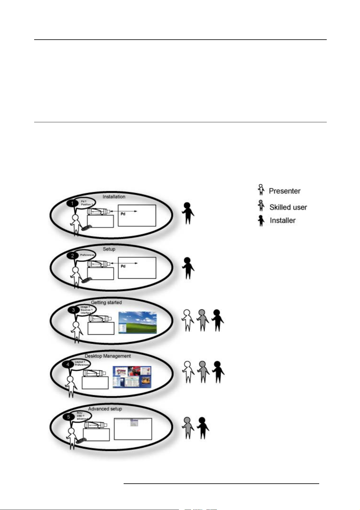
This manual contains 5 main parts :
1. Installation : The mechanical setup of the projector : removing from the shipping box , getting the projector ready to be started.
2. Setup: Adjusting the projection parameters in order to get the best image reproduction.
3. Getting started : Start the projector, create your desktop.
4. Desktop management : Adapting the desktop to the presenter’s needs.
5. Advanced operation : Using the remote control and the projector’s OSD for advanced setup.
Image 1-1
R5976992 ICON H250/400 13/12/2006 5
Page 12
1. Introduction
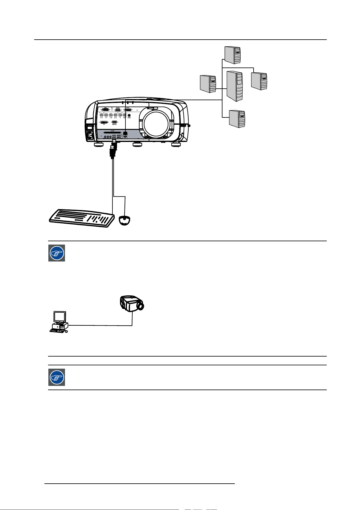
1.2 Network centric visualization
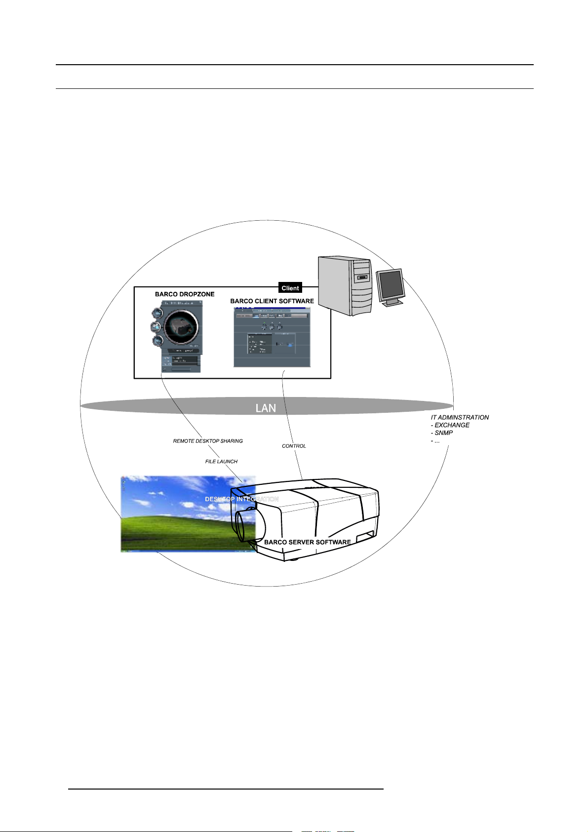
Architecture : Parts and Tools
• Barco Client software : runs on a client PC and allows control/diagnostics of the projector
• Barco DropZone : presentation tool, running on a client PC and allowing file manipulations (launch,...) and sharing with the
projector
• Barco Server software : runs on the projector (Server) and allows communication with the clients.
• Desktop integration : software running on the projector (Server) and allowing display content management on a Windows XP
desktop.
TM
Image 1-2
6 R5976992 ICON H250/400 13/12/2006
Page 13
2. PACKAGING
8
2.1 Unpacking
CEE7
European power plug to connect the power cord to the wall outlet.
ANSI 73.11
American power plug to connect the power cord to the wall outlet.
Content
• 1 projector (weight ± 14 kg or 31 lbs)
• 1 remote control unit RCU + 2 batteries.
• 2 power cables with outlet plug type CEE7 and ANSI 73.11.
• 1 owners manual
• 1 safety manual
• 1 CDROM (containing manuals)
2. Packaging
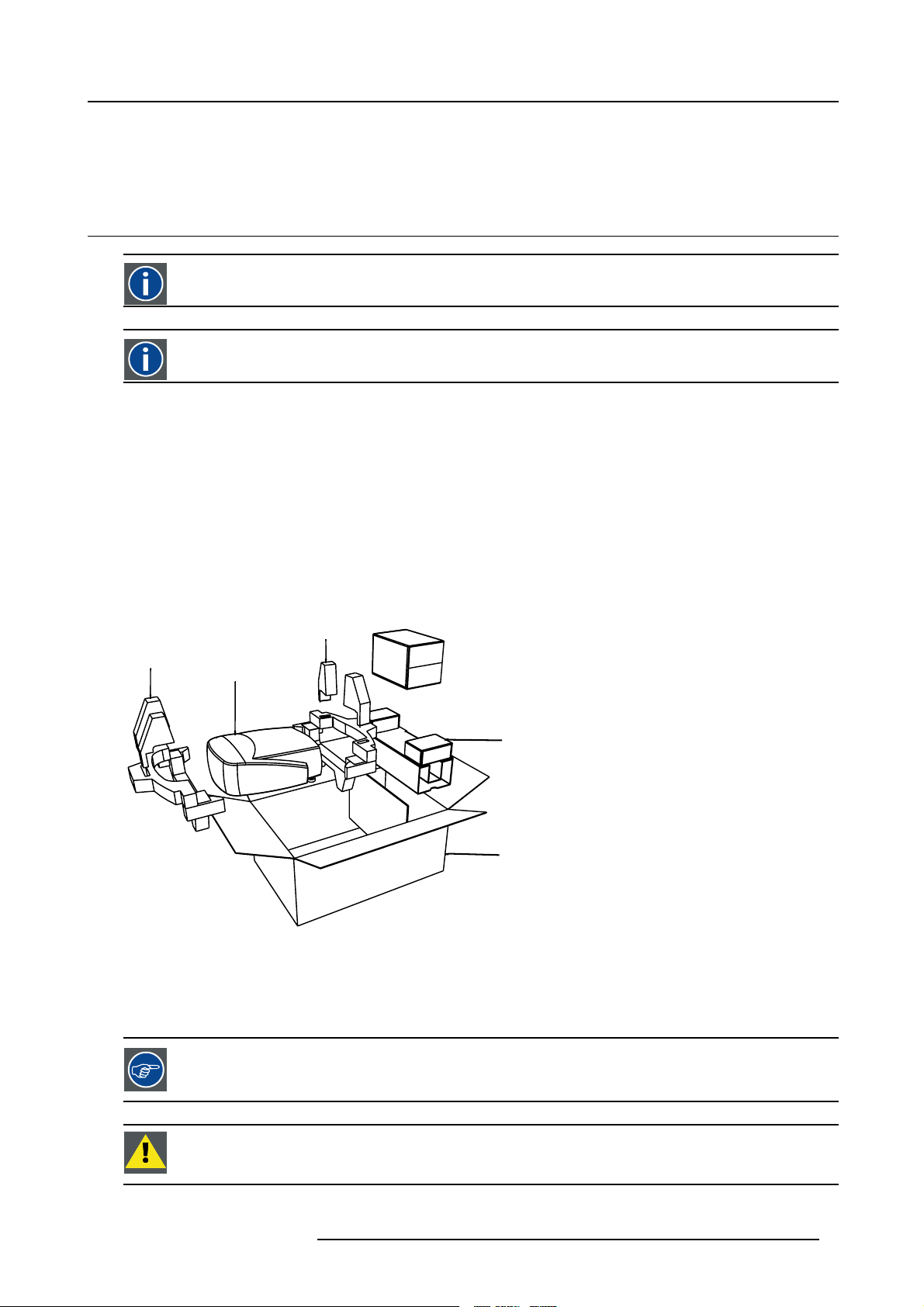
Form
The projector is packed in a carton box. To provide protection during transportation, the projector
package is secured with banding and fastening clips.
R824561
R824562
Projector
R824518
(+ cable basket R72440
R825784
Image 2-1
Lens packaging
The Lens is supplied as an individual item.
Thelensispackedinacartonbox.
is surrounded with foam. The
Save the original shipping carton and packing material, they will be necessary if you ever have to transport
the lens.
CAUTION: Never transport the projector with the lens mounted on it !
Always remove the lens before transporting the projector.
R5976992 ICON H250/400 13/12/2006 7
Page 14
2. Packaging
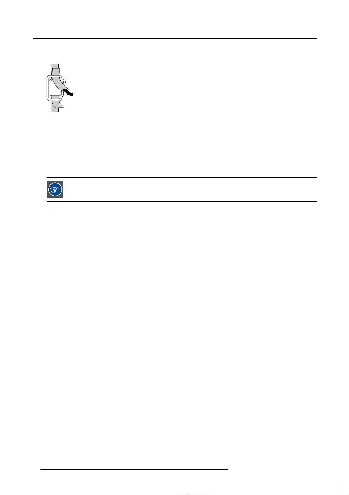
How to unpack the projector
1. Release the cord straps.
PULL
TO OPE
Image 2-2
2. Remove the assembly from the pallet
3. Remove the cardboard cover
4. Remove the large cardboard
5. Remove the 8 foam parts
6. Loosen and remove the 3 screws spacers fixing the projector to the wooden board
7. Remove the projector from the board
Save the original shipping carton and packing material, they will be necessary if you ever have to ship your
projector. For maximum protection, repack your projector as it was originally packed at the factory.
8 R5976992 ICON H250/400 13/12/2006
Page 15
3. Installation guidelines
3. INSTALLATION GUIDELINES
Overview
• Safety warnings
• Installation guidelines
• Network implementation
3.1 Safety warnings
WARNING: Before installing the projector, read first the safety instructions in the safety manual (R5975258)
delivered with the projector.
Insure that the projector is installed in an easy to evacuate room in case of a lamp explosion.
Mercury Vapor Warnings
Keep the following warnings in mind when using the projector. The lamp used in the projector contains mercury. In case of a lamp
rupture, explosion there will be a mercury vapor emission. In order to minimize the potential risk of inhaling mercury vapors:
• Ensure the projector is installed only in ventilated rooms.
• Replace the lamp module before the end of its operational life.
• Promptly ventilate the room after a lamp rupture, explosion has occurred, evacuate the ro
woman).
• Seek medical attention if unusual health conditions occur after a lamp rupture, explosion, such as headache, fatigue, shortness
of breath, chest-tightening coughing or nausea.
om (particularly in case of a pregnant
3.2 Installation guidelines
Ambient temperature check
Careful consideration of things such as image size, ambient light level, projector placement and type of screen to use are critical to
the optimum use of the projection system.
Max. ambient temperature : 40 °C or 104 °F
Min. ambient temperature : 0 °C or 32 °F
The projector will not operate if ambient air temperature falls outside this range (0°C- 40°C or 32°F-104°F).
Environment
Do not install the projection system in a site near heat sources such as radiators or air ducts, or in a place subject to direct sunlight,
excessive dust or humidity. Be aware that room heat rises to the ceiling; check that temperature near the installation site is not
excessive
CAUTION: Harmful Environmental Contamination Precauti
Environment condition check
A projector must always be mounted in a manner which en
as free flow at the ventilation outlets. The installation must also allow easy access to the consumable parts ( dustfilters, lamps, ...)
For installations in environments where the projector is subject to airborne contaminants such as that produced by smoke machines
or similar (these deposit a thin layer of greasy res
performance), then it is highly advisable and desirable to have this contamination removed prior to it reaching the projectors clean
air supply. Devices or structures to extract or shield contaminated air well away from the projector are a prerequisite, if this is not
a feasible solution then measures to reloca
projector never runs with dirty dustfilters as this will dramatically reduce the lifetime of the consumables. It is advised to clean the
dustfilters on a regular basis and to replace them at any lamp change. Barco reserves itself the right to refuse warranty replacement
of consumables if they have been used in a
has been specifically designed for cleaning optical parts, never use industrial strength cleaners on a projectors optics as these will
degrade optical coatings and damage sensitive optoelectronics .
idue upon the projectors internal optics and imaging electronic surfaces, degrading
te the projector to a clean air environment should be considered. Make sure that the
projector with dirty airfilters. Only use the manufactures recommended cleaning kit which
sures the free flow of clean air into the projectors ventilation inlets as well
on
R5976992 ICON H250/400 13/12/2006
9
Page 16
3. Installation guidelines
Failure to take suitable precautions to protect the projector from the effects of persistent and prolonged air contaminants will culminate in extensive and irreversible ingrained optical damage. At this stage cleaning of the internal optical units will be non-effective
and impracticable. Damage of this nature is under no circumstances covered under the manufactures warranty and may deem the
warranty null and void. In such a case the client shall be held solely responsible for all costs incurred during any repair. It is the
clients responsibility to ensure at all times that the projector is protected from the harmful effects of hostile airborne particles in the
environment of the projector. The manufacture reserves the right to refuse warranty repair if a projector has been subject to wantful
neglect, abandon or improper use.
What about ambient light ?
The ambient light level of any room is made up of direct or indirect sunlight and the light fixtures in the room. The amount of ambient
light will determine how bright the image will appear. So, avoid direct light on the screen. Windows that face the screen should be
covered by opaque drapery while the set is being viewed. It is desirable to install the projection system in a room whose walls and
floor are of non-reflecting material. The use of recessed ceiling lights and a method of dimming those lights to an acceptable level
is also important. Too much ambient light will ‘wash out’ of the projected image. This appears as less contrast between the darkest
and lightest parts of the image. With bigger screens, the ‘wash out’ becomes more important. As a general rule, darken the room to
the point where there is just sufficient light to read or write comfortably. Spot lighting is desirable for illuminating small areas so that
interference with the screen is minimal.
Which screen type ?
There are two major categories of screens used for projection equipment. Those us
projection applications. Screens are rated by how much light they reflect (or transmit in the case of rear projection systems) given a
determined amount of light projected toward them. The ‘GAIN’ of a screen is the term used. Front and rear screens are both rated
in terms of gain. The gain of screens range from a white matte screen with a gai
gain of 10 (x10) or more. The choice between higher and lower gain screens is largely a matter of personal preference and another
consideration called the Viewing angle. In considering the type of screen to choose, determine where the viewers will be located
and go for the highest gain screen possible. A high gain scre
more information about screens, contact your local screen supplier.
en will provide a brighter picture but reduce the viewing angle. For
ed for front projected images and those for rear
n of 1 (x1) to a brushed aluminized screen with a
Image size
The projector is designed for projecting an image size with a screenwidth from 1.00m (3.3ft) to 6.00m (19.7ft) with an aspect ratio of
16 to 9.
3.3 Network implementation
Network installation
The installation of the server in a Local Area Network must be done in the same way as the installation of a standard PC in that
particular network meaning that the sam
The assistance of qualified IT personnel is advised.
CAUTION: Important !
A Virus protection program should be installed and kept up to date to prevent virus infections.
CAUTION: The maintenance of the Serve
and accepted practice should be respected.
Backups should be taken on a regular basis.
In the same way virus updates should be done regularly.
Barco will not be held responsible for destroyed information in case of a hard disk breakdown or virus infection and has no obligation to pay for or reimburse for the cost of recovering data.
e rules and accepted practice should be respected.
r must be done in the same way as a PC meaning that the same rules
10 R5976992 ICON H250/400 13/12/2006
Page 17
4. INSTALLATION
L
ith diff
Overview
• Battery installation in the RCU
• Lens installation
• Removing the lens
• Lens range
• Lens Formulas
• Projector configuration
• Positioning the projector
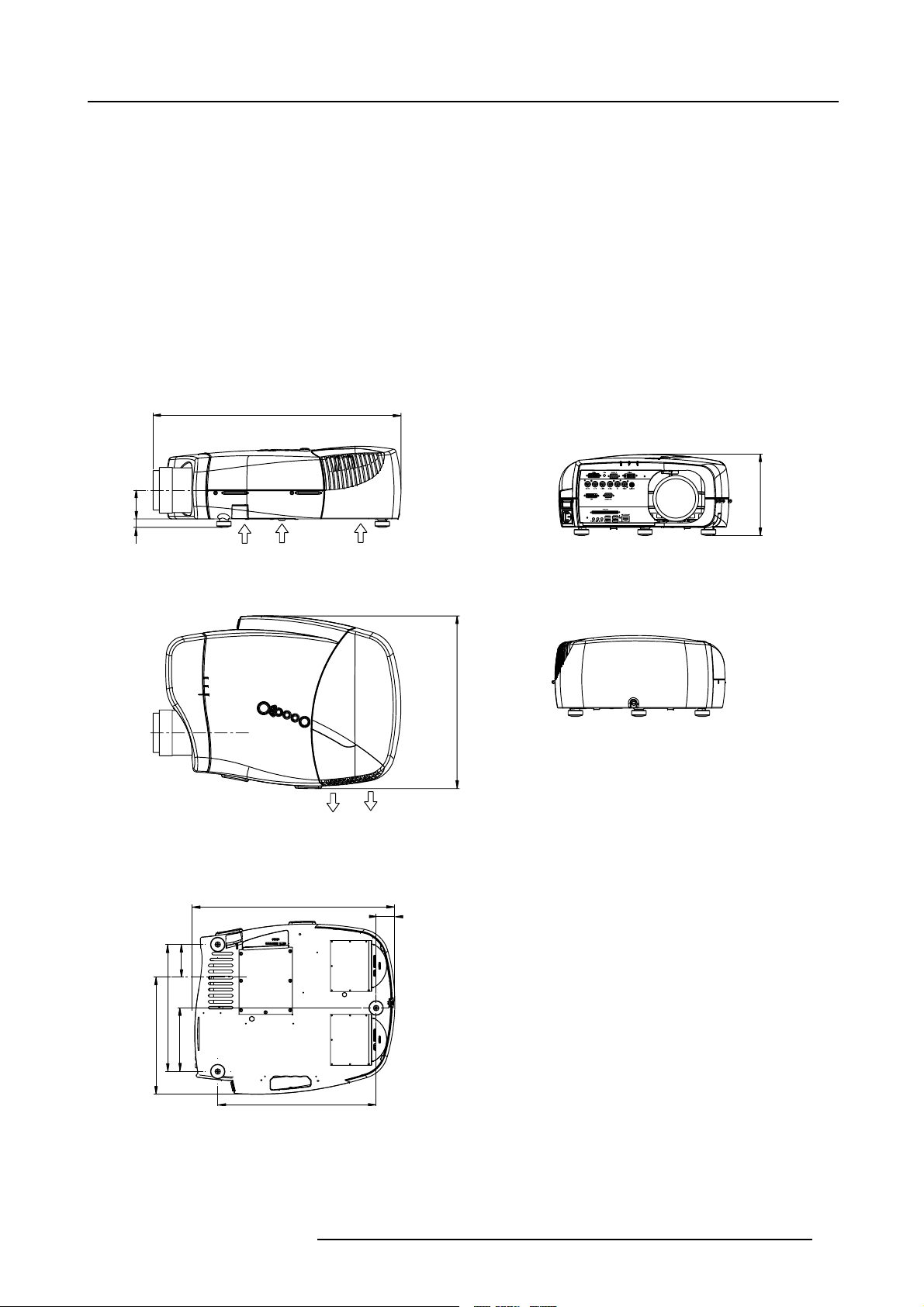
Dimensions
Dimensions are given in mm and inch ( 1inch = 25.4 mm)
ength w
erent lenses : see table
4. Installation
69
20
Cold air IN
487 (length without Cable Basket)
Cold air IN
415
Cold air OUT
45
195
78
305
281
152
Image 4-1
380
R5976992 ICON H250/400 13/12/2006 11
Page 18
4. Installation
Lens
CLD (1.2-1.6:1)
CLD (1.6-2.4:1)
CLD (2.4-4.3:1)
QCLD (1.1-1.3:1)
QCLD (0.85:1)
Length of projector
530 mm
525 mm
550 mm
580 mm
610 mm
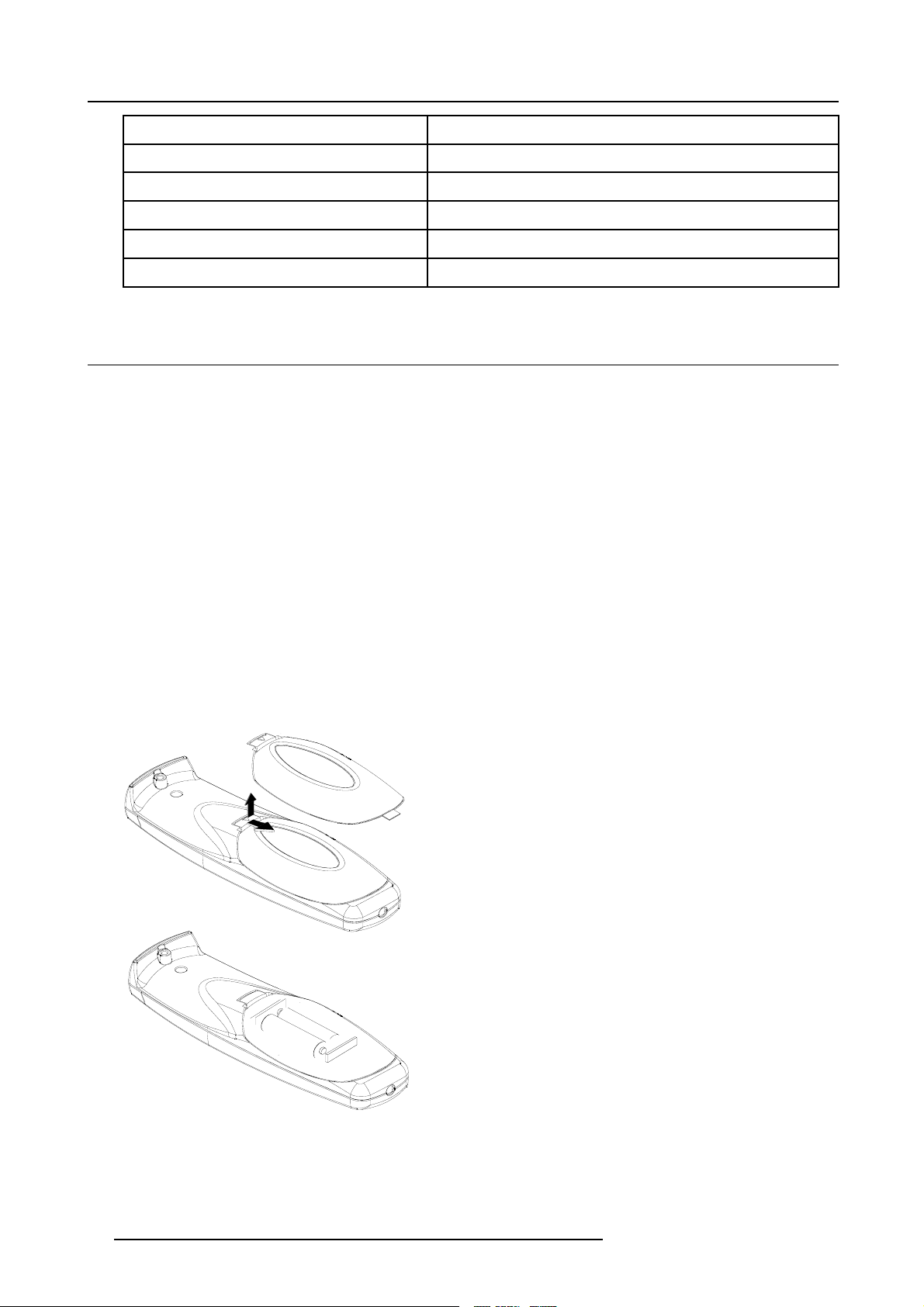
4.1 Battery installation in the RCU
How to install the battery
Two batteries are packed together with the RCU. Before using your RCU, install first these batteries.
1. Remove the battery cover on the backside by pushing the handle a little towards the bottom of the RCU.
2. Lift up the top side of the cover at the same time.
3. Insert the batteries as indicated in the RCU.
4. Put the battery cover on its place.
How to replace the batteries in the RCU
To replace the batteries :
1. Remove the battery cover on the backside by pushing the handle a little towards the bottom of the RCU.
2. Lift up the top side of the cover at the same time.
3. Push on the + side of the battery towards the - side
4. Lift up the battery at the same time.
5. Repeat for the second battery.
6. Insert the batteries as indicated in the RCU (battery type AA or LR6 or equivalent).
7. Put the battery cover on its place.
Image 4-2
12 R5976992 ICON H250/400 13/12/2006
Page 19
4.2 Lens installation
How to install ?
1. Take the lens out of its packing material
2. Fix the lens by placing it in the housing
Image 4-3
Note: In case of a motorized lens the female jack must be in front of the male jack located in the upper-left part of the housing
in the projector
3. Push carefully to lock the lens in the housing
4. Installation
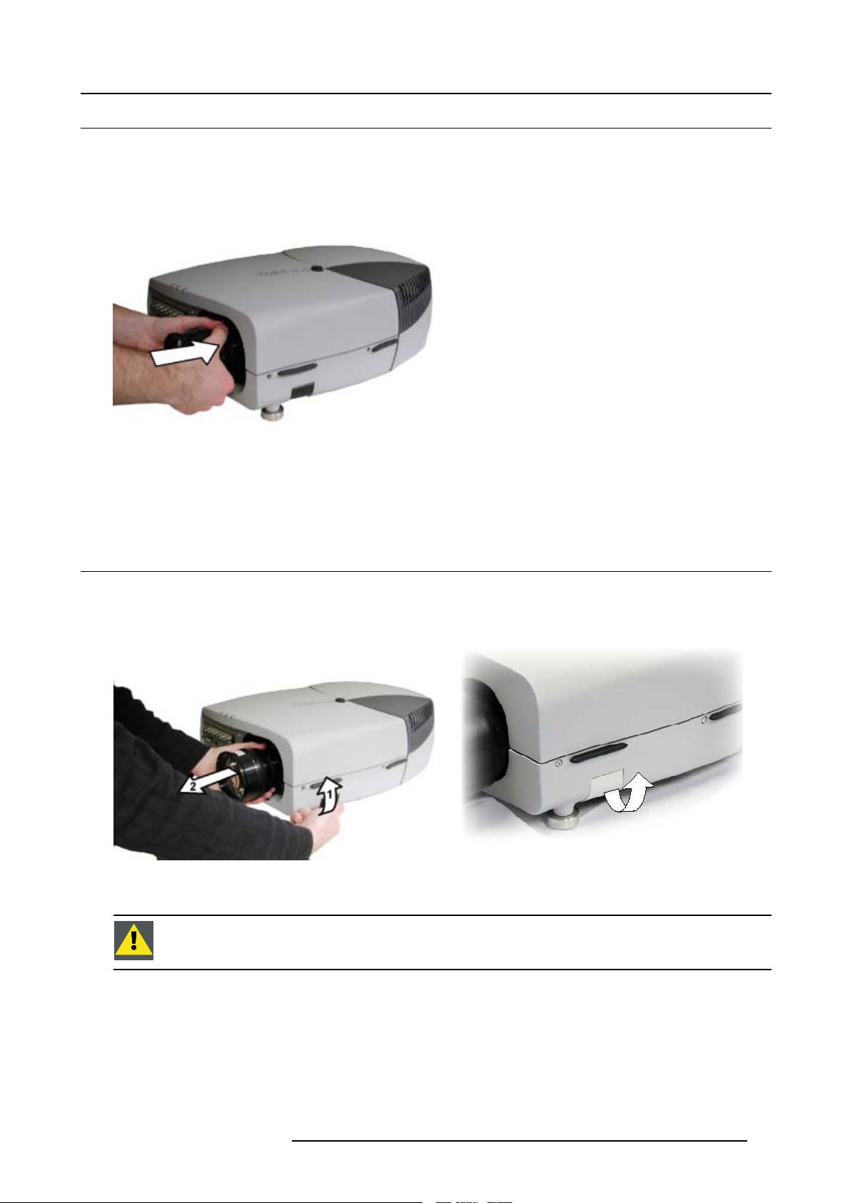
4.3 Removing the lens
How to remove the lens ?
1. Unlock the lens by pulling the handle located on the right side
Image 4-4
2. Remove the lens out of its housing
CAUTION: Never transport the projector with the lens mounted on it !
Always remove the lens before transporting the projector.
of the projector
Image 4-5
location of the lens handle
R5976992 ICON H250/400 13/12/2006 13
Page 20
4. Installation
4.4 Lens range
Overview table
Lens
QCLD (0.85:1)
QCLD (1.1-1.3:1)
CLD (1.2-1.6:1)
CLD (1.6-2.4:1)
CLD (2.4-4.3:1)
Partnumber
R9849860
R9849850
R9849870
R9849880
R9849890
See the Maintenance appendix for more information about lens cleaning.
4.5 Lens Formulas
Formulas
Lenses
QCLD (0.85:1) PD=0.79XSW+0.06 PD = 0.79 X SW + 2.36
QCLD (1.1-1.3:1) PD
Metric Formulas (meter) Inch formulas (inch)
=1.02XSW+0.05
min
=1.2XSW+0.06
PD
max
PD
=1.02XSW+1.97
min
PD
max
= 1.2 X SW + 2.36
CLD (1.2-1.6:1) PD
CLD (1.6-2.4:1) PD
CLD (2.4-4.3:1) PD
= 1.1 X SW + 0.02
min
=1.51XSW+0.02
PD
max
=1.46XSW+0.00
min
= 2.21 X SW - 0.02
PD
max
= 2.2 X SW - 0.03
min
= 3.99 X SW - 0.01
PD
max
PD
min
=1.51XSW+0.79
PD
max
PD
=1.46XSW+0.00
min
PD
max
PD
min
PD
max
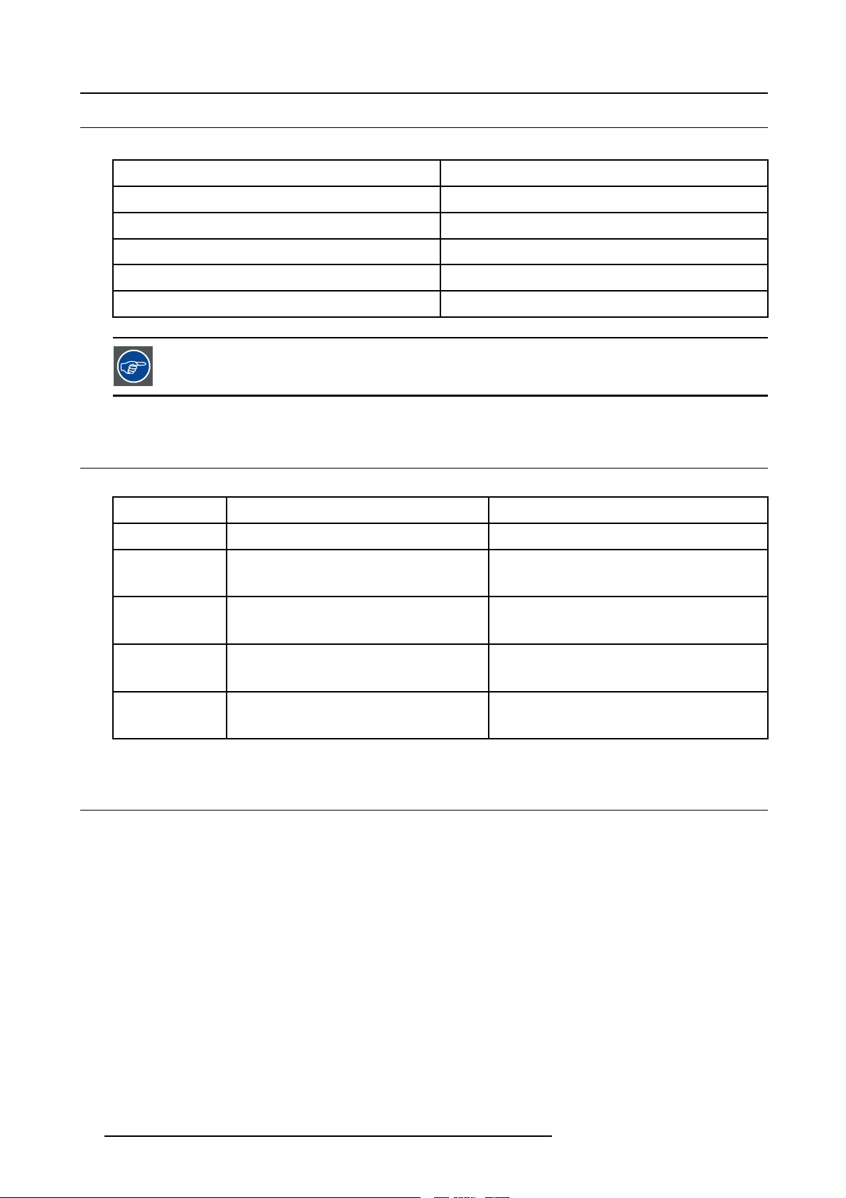
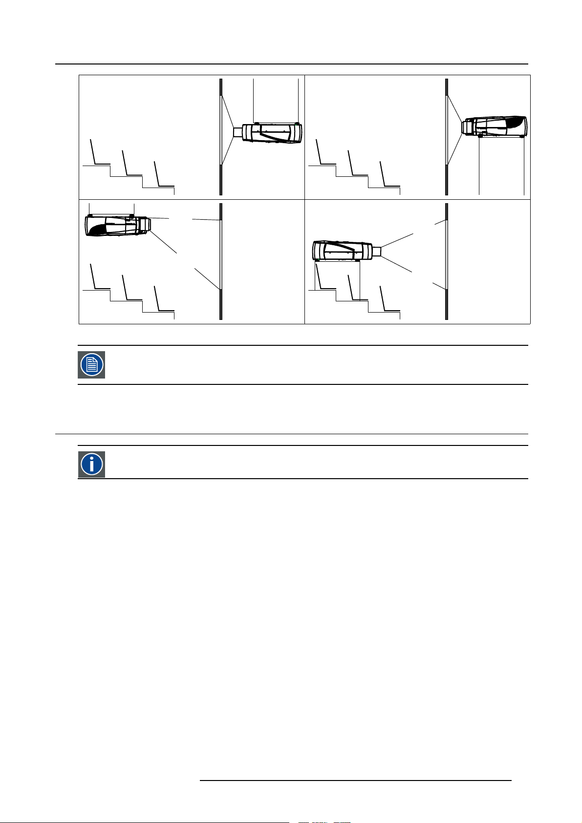
4.6 Projector configuration
The different configurations
Depending on the installation the projector can be mounted in different ways, the 4 different configurations are:
1. Rear/Ceiling
2. Rear/Table
3. Front/Ceiling
4. Front/Table
=1.1XSW+0.79
= 2.21 X SW - 0.79
= 2.2 X SW - 1.18
= 3.99 X SW - 0.39
14
R5976992 ICON H250/400 13/12/2006
Page 21
4. Installation
1
3
Image 4-6
2
4
The configuration should also be communicated to the projector. This is done in the Installationmenu through
the Projector Configuration parameter. (See Setup section)
4.7 Positioning the projector
On-Axis projection
Projection where the projector is positioned so as to have the centre of the lens coinciding with the centre of the screen.
Positioning the projector
The position of the projector with reference to the screen may also be different depending on the installation. Basically the projector
can be positioned in an On-Axis or Off-Axis configuration. Several parameters can be calculated determining the position in any
installation.
R5976992 ICON H250/400 13/12/2006
15
Page 22
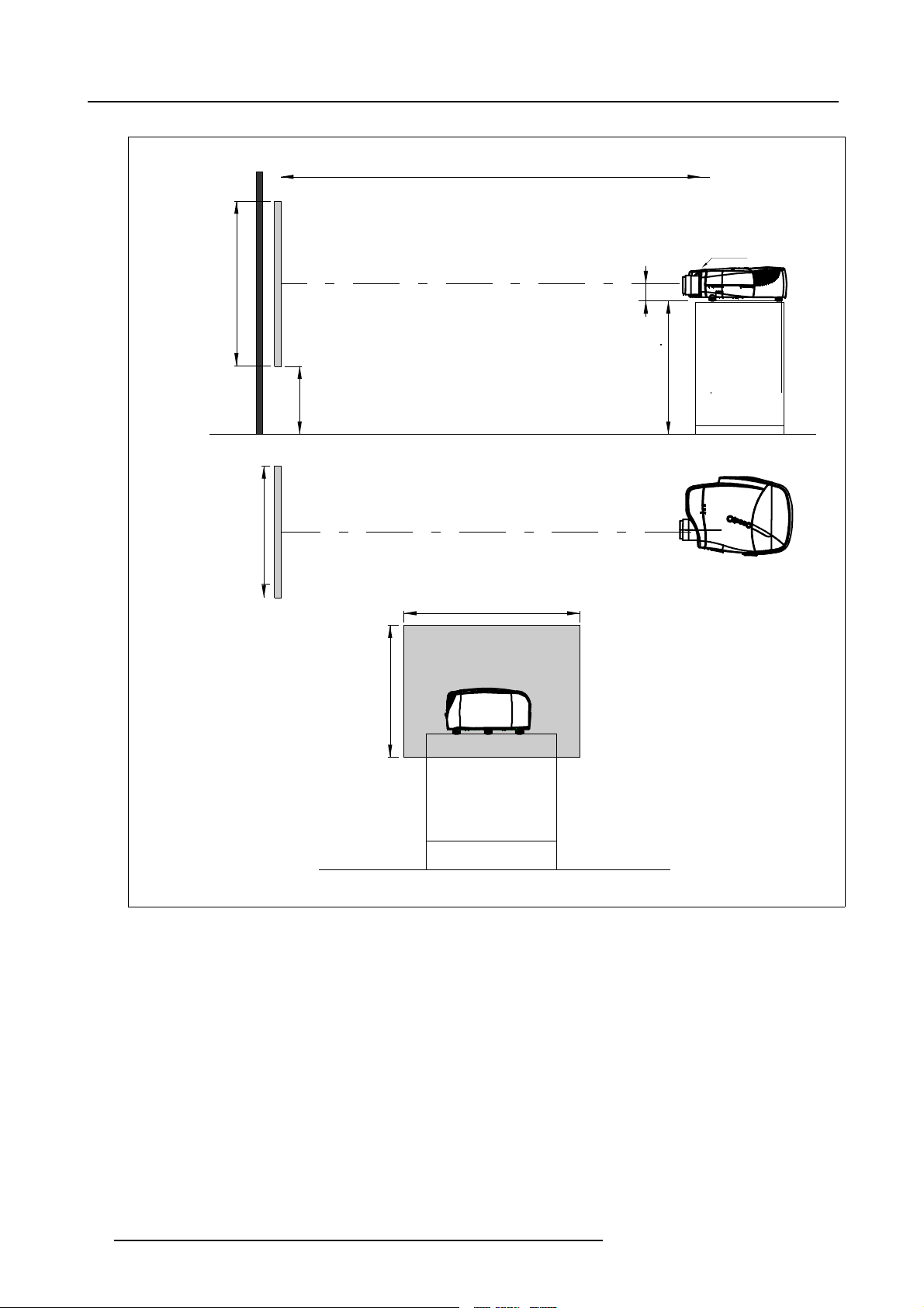
4. Installation
a
SH
PD
P
front plate
x
A
S
CD=SH/2+B-A
B
F
b
SW
S
SW
c
SH
F
Image 4-7
16 R5976992 ICON H250/400 13/12/2006
Page 23
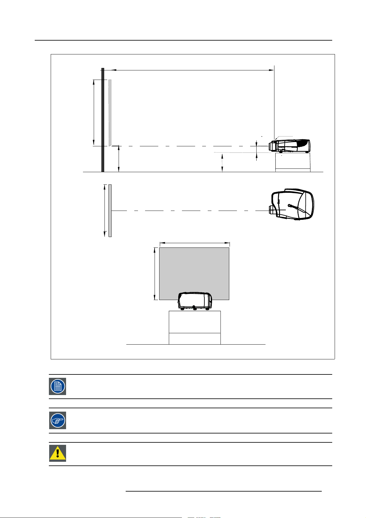
PD
4. Installation
a
b
c
SH
SW
front plate
S
A
B
S
SH
CD=B-A
F
SW
P
F
Image 4-8
A 100% Off-Axis position means that the position of the centre of the lens is shifted by half the screen height.
Never use a short throw lens in an Off-Axis installation. Shifting the lens will not guarantee optimal image
quality.
CAUTION: Only for projectors containing a Server (Single Board Computer) : The harddisk in the server is
formatted in horizontal position but can operate in all axes (6 directions). The projector should not be tilted
more then +/- 5 degrees from these positions, otherwise error rates will increase.
R5976992 ICON H250/400 13/12/2006 17
Page 24
4. Installation
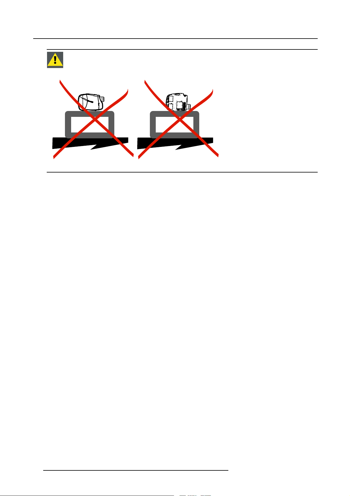
CAUTION: Never place the projector on either side !
Floor
Image 4-9
Floor
18 R5976992 ICON H250/400 13/12/2006
Page 25
5. CONNECTIONS
Overview
• Power connection
• Connections
• Signal connections
5.1 Power connection
Power connection
1. Use the supplied power cord to connect the projector to the power outlet.
2. Plug the female power connector into the male connector at the front of the projector.
5. Connections
Image 5-1
Power connection
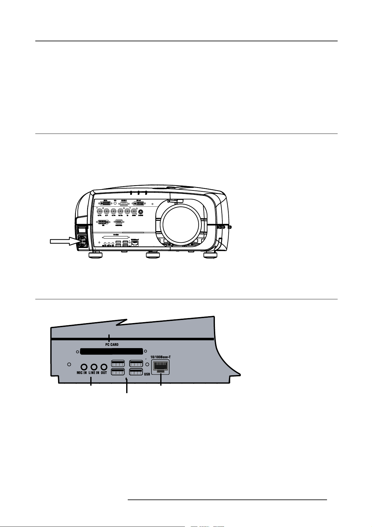
5.2 Connections
Server section layout
PCMCIA
AUDIO
USB 1
USB 2
Image 5-2
USB 3
USB 4
How to connect the iCon server ?
1. Use the 2 RJ45 connector to connect the server to the installed network.
2. Use the USB ports to connect per
3. Use the PCMCIA slot to connect a Wireless LAN card or other optional inputs like Bluetooth, Modem cards,...
Note: recommended card type:
-The card should be a type II card.
-The card should be Windows
ipherals such as a mouse or a keyboard, ...
RJ45
TM
XP compatible
R5976992 ICON H250/400 13/12/2006
19
Page 26
5. Connections
LAN
RJ45
USB
Image 5-3
A
Image 5-4
Point to point configuration
B
In case of a temporary configuration (demo purposes) one can use the point to point configuration, the connection being done via RJ45 connections using a crossed UTP cable.
The connection of the server sec
tion of the projector should be done in the same way as for a standard PC. If
necessary, contact your local IT administrator.
20 R5976992 ICON H250/400 13/12/2006
Page 27
5. Connections
5.3 Signal connections
Overview
• The input section
• Connecting a Composite video signal
• Connecting an S-Video signal
• Connecting an RGB signal
• Connecting a Component Video signal
• Connecting a DVI signal
• Connecting a computer signal
• The DVI output
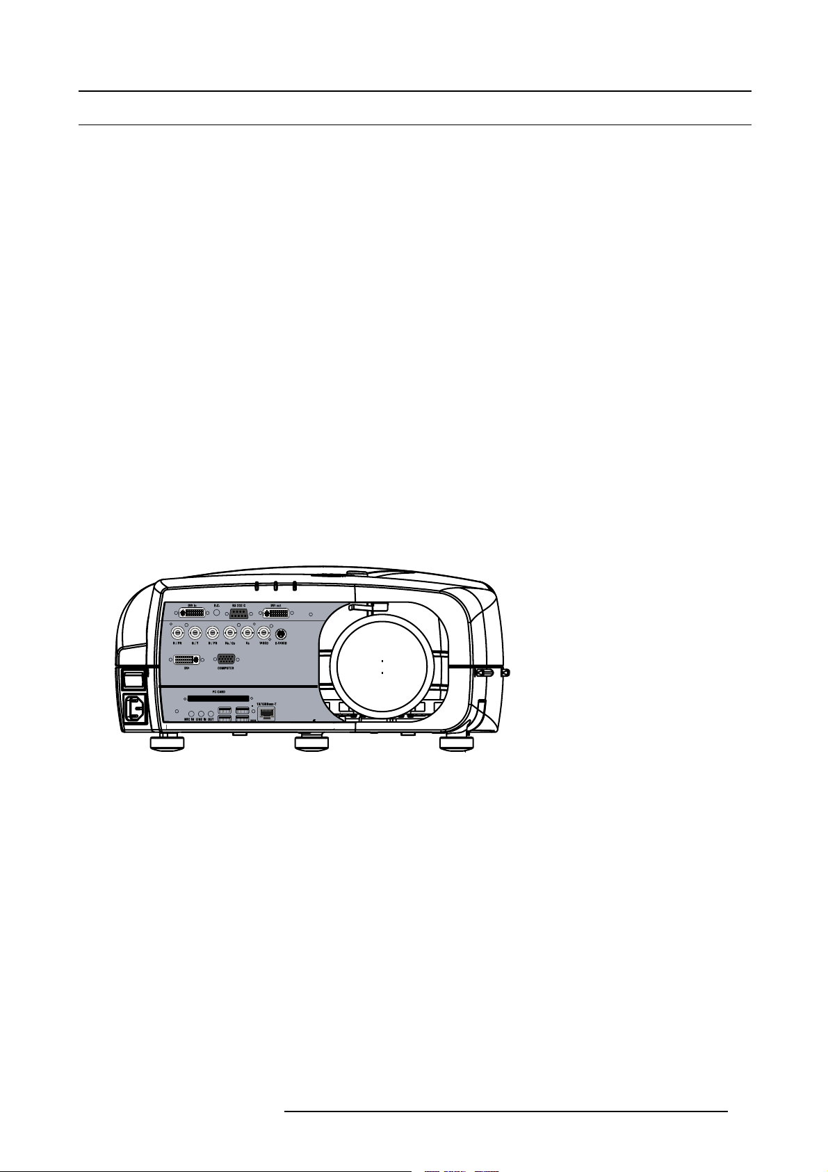
5.3.1 The input section
Input layers
The input section is located at the front of the projector and is composed of 3 layers which can be equipped with different input
modules depending on the ordered options .
The standard layers :
• Layer 1: DVI Input/Output module:
• Layer 2: RGBHV & Video analog input module
• Layer 3: DVI & Computer (D15) input module
• Layer 4 : Single Board Computer connections
The different available options :
• One extra RGBHV & Video analog input module on Layer 3
• HD SDI/SDI input output input module on Layer 3
Image 5-5
R5976992 ICON H250/400 13/12/2006 21
Page 28
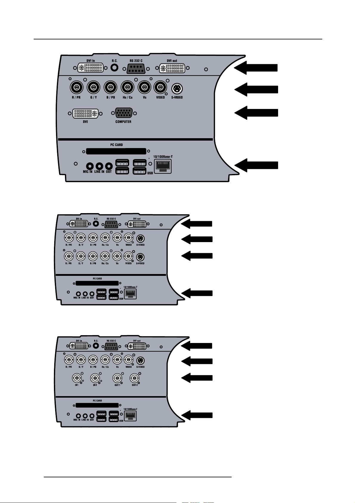
5. Connections
Image 5-6
Input section
L1
LAYER 1
L1
LAYER 2
L1
LAYER 3
L1
LAYER 4
Image 5-7
Input with 2 RGB analog input modules (ordered with RGB Option)
L1
LAYER 1
L1
LAYER 2
L1
LAYER 3
L1
LAYER 4
L1
LAYER 1
L1
LAYER 2
L1
LAYER 3
L1
LAYER 4
Image 5-8
Input with HDSDI/SDI module (ordered with HDSDI/SDI Option)
22 R5976992 ICON H250/400 13/12/2006
Page 29
5. Connections
r
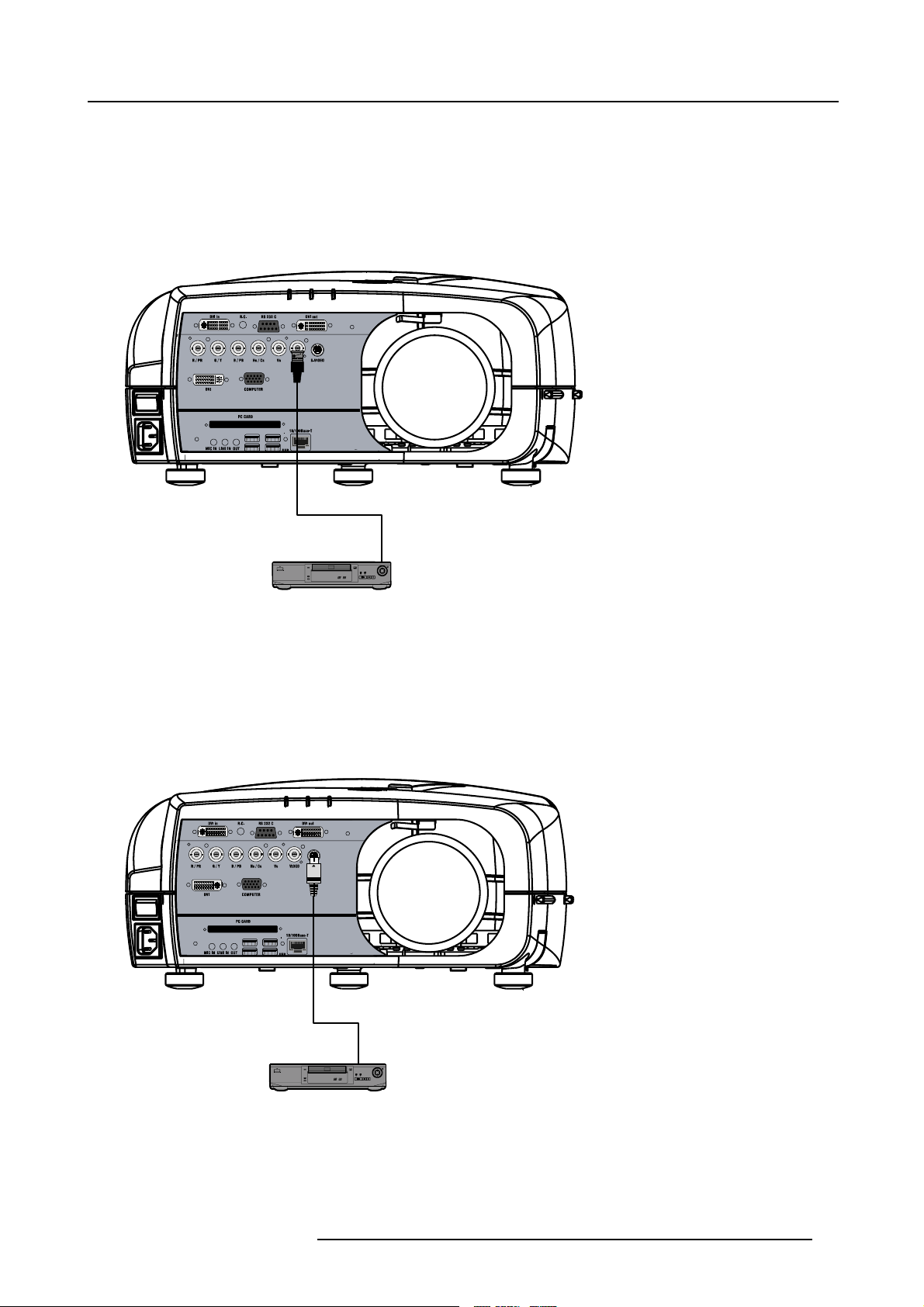
5.3.2 Connecting a Composite video signal
Composite video connection
A Composite video signal is often available on a yellow cinch connector of a Camera, VCR or DVD player, in this case you will need
an adapter cable cinch/BNC to connect to Video input of the RGB board.
How to connect a composite video signal
1. Connect the BNC connector to the projector’s BNC video input
Image 5-9
DVD Playe
5.3.3 Connecting an S-Video signal
S-Video connection
An S-Video signal is available on the Mini-Din connector o
How to connect an S-Video connection
1. Connect the mini din connector to the projector’s S-Video input
f a camera, VCR or DVD player.
Image 5-10
DVD Player
5.3.4 Connecting an RGB signal
RGB data connection
The RGB input consists of 5 BNC
R5976992 ICON H250/400 13/12/2006
23
Page 30
5. Connections
• 3 for the color signals R,G,B
• 2 for the sync signals H (horizontal sync), V (vertical sync)
RGBS : If the source disposes of a composite sync output i.e. one wire includes the horizontal and the vertical sync than the V BNC
must not be connected, resulting in 4 BNC being connected (V is free).
B : If the source disposes of a sync on Green output i.e. the Green color signal includes the horizontal and the vertical sync
RG
s
than the H and V BNC’s must not be connected, resulting in 3 BNC being connected (H and V are free).
BNC Connector
R
RGBHV
RGsB
RGBS
Table 5-1
HowtousetheBNC’sincaseofdifferentRGBsignals
R
R
R
G
G
G
s
G
The RGB 5 BNC input can also be used to connect a component video source : see Connecting a Component
video source.
How to connect an RGB signal
1. Connect the 5 or 4 BNC cables to the projector’s RGB input
B H V
B H V
B
B
- -
S
-
Image 5-11
5.3.5 Connecting a Component Video signal
Component Video
In Component Video the term component describes a number (3) of elements that are needed to make up the video
picture, these components are R-Y/Y/B-Y. A composite video signal on the other hand contains all the information
eded for the color picture in a single channel of information
ne
24 R5976992 ICON H250/400 13/12/2006
Page 31

How to connect a Component video signal
1. Connect the 3 BNC connectors to the projector’s RGB input
5. Connections
Image 5-12
In case of a “progressive scan” component video source, the notation used is PR/Y/PB
DVD Player
5.3.6 Connecting a DVI signal
DVI
Digital Visual Interface is a display interface developed in response to the proliferation of digital flat panel displays.
The digital video connectivity standard that was developed by DDWG (Digital Display Work Group). This connection
standard offers two different connectors: one with
that handles both digital and analog video. This standard uses TMDS (Transition Minimized Differential Signal) from
Silicon Image and DDC (Display Data Channel) from VESA (Video Electronics Standards Association).
DVI can be single or dual link.
Input specifications
Single link DVI
Differential input voltage: 200 mV - 800mV
How to connect a DVI signal ?
1. Connect the DVI cable to the DVI input on Layer 0 or on Layer 2
24 pins that handles digital video signals only, and one with 29 pins
R5976992 ICON H250/400 13/12/2006
25
Page 32

5. Connections
Image 5-13
Left side : DVI connection on Layer 2, right side : DVI connection on Layer 0
Note that the 2 DVI outputs are identical and are processed in the same way in the projector
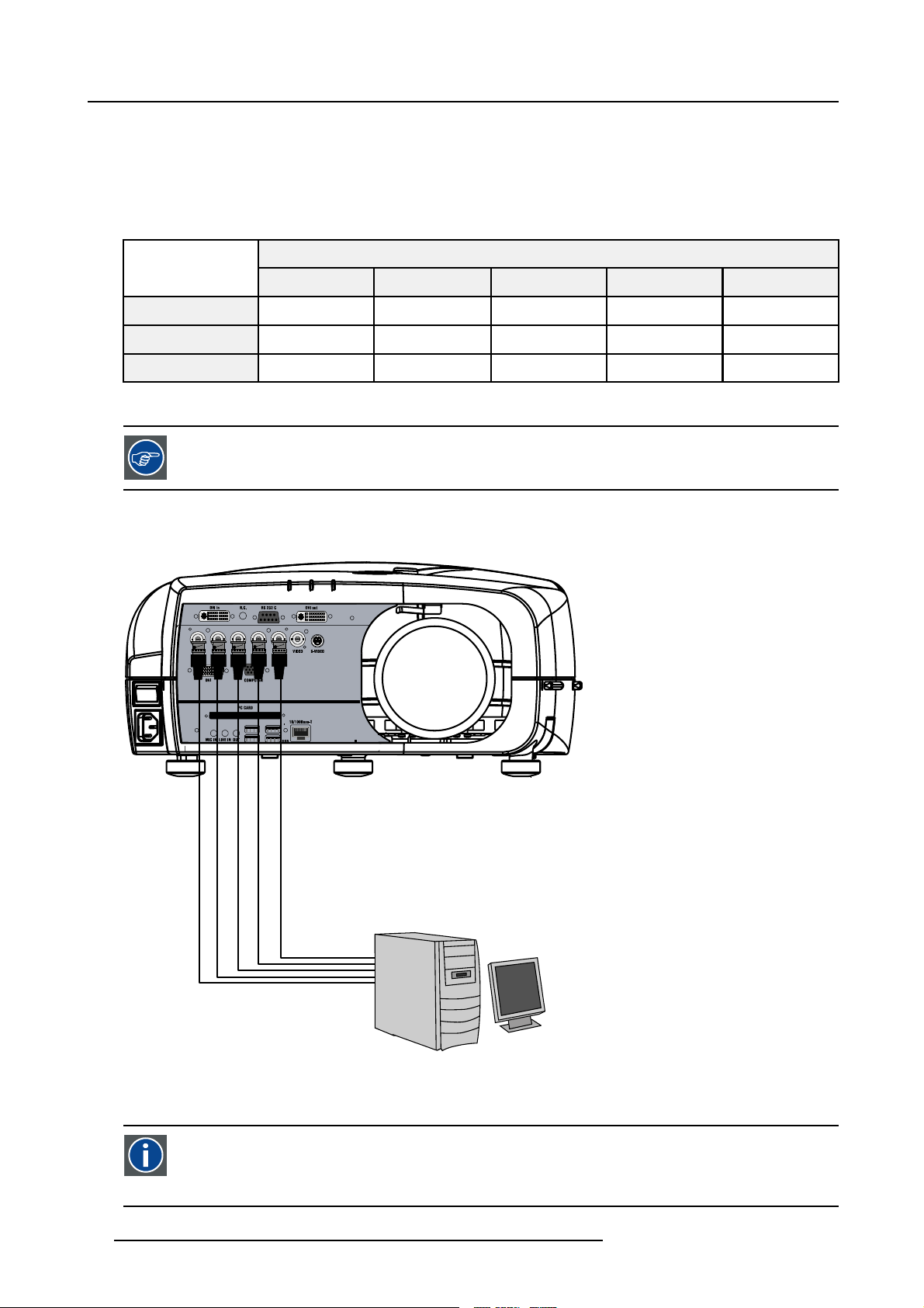
5.3.7 Connecting a computer signal
How to connect a computer signal
1. Connect the D15 connector to the projector’s Computer input
Image 5-14
5.3.8 The DVI output
What can be done ?
The DVI output is a copy of the projector’s complete desktop image (containing also the source windows) and can be connected
to an external monitor. Some monitors can fail to synchronize on the DVI signal, in this case disable the Full screen synchronous
representation function in the Display Settings menu.
26
R5976992 ICON H250/400 13/12/2006
Page 33

Image 5-15
5. Connections
Image 5-16
The DVI output is at 1920x1080 (projector ’s native resolution)
R5976992 ICON H250/400 13/12/2006 27
Page 34

5. Connections
28 R5976992 ICON H250/400 13/12/2006
Page 35

6. SETUP
Overview
• RCU & Local keypad
• Terminology overview
• Switching on
• Setting up the RCU address
• Setting up the projector address (only if necessary)
• Setting up the orientation
• Adjusting the lens
• Setup the baudrate for serial communication
• Setting the server ON/OFF state
• Preferences
• Installing the software
• Configuring the client software
• Configuring the Server software
• DropZone settings
•Startup
6. Setup
6.1 RCU & Local keypad
How controlling the projector ?
The projector can be controlled by the local keypad or by the remote control unit.
Location of the local keypad ?
The local keypad is located on the topside of the projector.
For key overview: "Terminology overview", page 31
R5976992 ICON H250/400 13/12/2006
29
Page 36

6. Setup
Image 6-1
Local keypad layout
Remote control functions.
This remote control includes a battery powered infrared (IR) transmitter that allows the user to control the projector remotely. This
remote control is used for source selection, control, adaptation and set up. It includes automatic storing of picture controls (Brightness, Sharpness...) and settings.
Other functions of the remote control are :
• switching between stand by and ope
• switching to "pause" (blanked picture, full power for immediate restarting)
• direct access to all connected sources.
rational mode.
Diagnose LED’s
Green
LED1
LED2
LED3 IR acknowledgement continue : standby
cool down sequence: flickers 60 seconds (120
seconds in case of iQ 400 series) after switching
to standby
only for the versions containing a server:
shows when projector is in
standby and server is active.
Red
rescue program (software error)
hardware error
flickers : Security = ON
30 R5976992 ICON H250/400 13/12/2006
Page 37

6.2 Terminology overview
Overview
The following table gives an overview of the keys.
6. Setup
Image 6-2
1 Function keys
2 MENU Menu key, to enter or exit the Toolbar menu.
3 Address key
4
LOGO key allows to recall the stored Logo (not in PiP mode)
5
PAU SE to stop projection for a short time, press ’PAUSE’. The image disappears but full power is
6
STBY standby button, to start projector when the power switch is switched on and to switch off the
7
MUTE
8
AUTOIMAGE Auto image, to center the image on the active LCD surface.
9 Digit buttons direct input selection.
9b
SOURCE button this button allows to switch through the active (scanned) inputs
R5976992 ICON H250/400 13/12/2006 31
user programmable keys with functions for direct access.
(recessed key), to enter the address of the projector (between 0 and 9). Press the recessed
address key with a pencil, followed by pressing one digit button between 0 and 9.
retained for immediate restarting.
projector without switching off the power switch.
Attention : Switching to Standby. When the projector is running and you want to
go to standby, press the standby
to interrupt the sound reproduction (audio = optional.
key for 2 seconds.
Page 38

6. Setup
10 Lens control
11
VOL use this button to obtain the desired sound level (audio = optional)
use these buttons to obtain the desired ZOOM, SHIFT, FOCUS.
12 Picture controls use these buttons to obtain the desired picture analog level.
13
DIGI ZOOM allows a digital Zoom of a part of the image
14 FREEZ
15 PIP
16 ENTER
press to freeze the projected image.
allows to activate the PICTURE IN PICTURE mode
to confirm an adjustment or selection in the MENU.
On the local keypad the ENTER button additionally accesses the PIP window resize function
17
Cursor keys Cursor Keys on RCU or on the local keypad : to make menu selections or to access the
toolbar.
18
BACK to leave the selected menu or item (go upwards to previous menu).
19
EFFECTS
20
PIP ADJUST allows to select a PiP window and change its configuration on screen
21
RC operating indication lights up when a button on the remote control is pressed. (This is a visual indicator to
not yet implemented
check the operation of the remote control)
22 IR receiver IR receiver
Table 6-2
ordernumber RCU: R763794K
6.3 Switching on
How to switch on.
1. Press the power switch to switch on the projector.
- When ’0’ is pushed in, the projector is switched off.
- When ’1’ is pushed in, the projector is switched on
The projector starts in standby mode, LED3 is red.
Starting image projection.
1. Press Standby key once on the local keypad or on the remote control.
MENU BACK
EN T ER
PA U
9
Image 6-3
PI P
SE
L
OGO
DIGI
Z
M
OO
0
PH A
SE
It may take about 60 seconds before image projection, i.e. no projection until the completion of several operations (software initialization,...).
32 R5976992 ICON H250/400 13/12/2006
Page 39

If the Security mode is enabled, a textbox will be displayed for PIN code entry, see Security settinginthe
Installation menu
6.4 Setting up the RCU address
What has to be done ?
To allow the communication between the RCU and the projector the RCU has to be programmed with the same address as the
projector.
This address must be in the range 0–9.
To know the address of the projector, one can visualize it in projection mode (on screen) as well as in standby mode (shown with
the LED’s on top cover of the projector).
For more info on addresses see the appendix
6. Setup
At this stage the image projected may happen to be upside down or mirrored, this can
be set in the Installation
menu under Projector orientation (see further setting up the projector’s orientation).
Displaying the Projector Address in Standby mode
1. Press the Address key (recessed key on the RCU) with a pencil.
MENU BACK
EN T ER
PA U
9
Image 6-4
PI P
SE
L
OGO
DIGI
Z
M
OO
0
PH A
SE
All the LED’s (3) on the top cover of the projector go out.
Then LED1 starts blinking green the number of hundreds. After that LED2 starts blinking the number of tens. Finally LED3 starts
blinking green the number of units. If this is done, the original status of the LED’s is restored.
Displaying the Projector Address in projection mode)
1. Press the Address key (recessed key on the RCU) with a pencil.
The projector’s address will be displayed on the
screen in a Textbox
Programming the RCU
1. Push the address key If the address is not entered within 5 seconds, the RCU returns to its default address (zero address) and
controls then all projectors in the room.
2. Enter the same address with the digit buttons within 5 seconds after pushing the address key.
The projector can now be controlled with the RCU.
For example : if the projector address is 3, then press "3" on the RCU to set the RCU’s address to match the
projector’s address.
R5976992 ICON H250/400 13/12/2006 33
Page 40

6. Setup
Common address/Projector address : Beside the projector address, the projector disposes also of a Common
address which can be set to “0” or “1” (by default “0”).
In other words, an RCU set to address “0” will always control a projector regardless of its projector address
(since it uses the common address).
6.5 Setting up the projector address (only if necessary)
What can be done ?
The projector is shipped with projector address set to ”0”
In some cases the projector address must be changed, for example if an unique RCU is used to control 2 or more projectors (independently).
In the OSD menu Projector Address, the following addresses can be programmed :
• Projector address: address defined by the user, may be from 0 to 255
0-9 is used for RCU communication, 0–255 being used for RS232 serial communication.
• Common address : address may be 0 or 1
For more info on addresses see the appendix
How to change the projector’s address ?
1. Press MENU to activate the Tool bar
2. Press → to select the Installation
3. Press ↓ to Pull down the Installation menu
4. Use ↑ or ↓ to select Projector address
Image 6-5
5. Press ENTER
A dialog box appears on the screen
Image 6-6
6. Enter the new projector address with the digit keys on the RCU, the local keypad or the cursor keys.
34
R5976992 ICON H250/400 13/12/2006
Page 41

How to change the common address ?
1. Proceed in the same way as for the projector address
6.6 Setting up the orientation
What must be done ?
Depending on the mechanical orientation of the projector, the projector’s internal settings have to be adapted.
The projector is shipped (default) with a table/front orientation.
How to set the orientation ?
1. Press MENU to activate the Tool bar
2. Press → to select the Installation item
3. Press ↓ to Pull down the Installation menu
4. Use ↑ or ↓ to select Orientation
5. Press → to pull down the menu
6. Use ↓ or ↑ to select the desired orientation
6. Setup
Image 6-7
7. Press ENTER
The projection is adapted and a bullet shows the active configuration.
6.7 Adjusting the lens
What must be done ?
Depending on the projection distance and the lens used, the image may not be at the desired size, position and/or may be out of
focus.
The projector will always allow you to shift yo
In addition, motorized lenses will also allow you to Zoom and focus the image.
All these lens parameters can be adjusted using the RCU, the local keypad or in the Installation menu of the projector’s OSD.
• Zoom (only for motorized lenses)
• Focus (only for motorized lenses)
• Vertical Shift
The lens can also be adjusted via the dedicated keys on the remote.
R5976992 ICON H250/400 13/12/2006 35
ur image vertically as well as horizontally (when available) to position it on the screen.
Page 42

6. Setup
How to Zoom/focus or shift via the RCU (or keypad)
1. Press LENS ZOOM or
LENS FOCUS or LENS SHIFT on the RCU
4
3
1
Image 6-8
2. Use the arrow keys to adjust
MENU BACK
PA U
9
Image 6-9
2
LENS
ZOOM
LENS
FOCUS VOL
SE
L
OGO
0
BRIGHTN
CONTR
LENS
SH IF T
EN T ER
PI P
DIGI
Z
M
OO
PH A
SE
How to Zoom/focus or shift in the OSD ?
1. Press MENU to activate the Tool bar
2. Press → to select the Installation
3. Press ↓ to Pull down the Installation menu
4. Use ↑ or ↓ to select Lens Adjustments...
Image 6-10
5. Press ENTER
36
R5976992 ICON H250/400 13/12/2006
Page 43

A text box appears on the screen, follow the instructions.
Image 6-11 Image 6-12
6. Setup
The use of a sheet o
for best focus)
Vertical shift range : -25%(down) to 140%(up)
Except for the
f paper held in front of the screen can be useful to determine the focus plane (position
QCLD (0.85:1) : -25%(down) to 30%(up)
6.8 Setup the baudrate for serial communication
What can be done ?
The RS232 IN port of the projector allows you to communicate with any other equipment disposing of an RS232 port (generally a
PC used to upgrade the projector’s firmware) using the RS232 protocol. The baudrate must be set to the same value on both the
projector and the other equipment.
How to change the baudrate?
1. Press MENU to activate the Tool bar
2. Press → to select the Installation item
3. Press
4. Use ↑ or ↓ to select RS232 baudrate
↓ to Pull down the Installation menu
Image 6-13
5. Press → to pull down the menu
6. Use ↓ or ↑ to select the desired baudrate
R5976992 ICON H250/400 13/12/2006
37
Page 44

6. Setup
7. Press ENTER
Always select the highest rate (115200) unless otherwise specified.
6.9 Setting the server ON/OFF state
Starting up
The Server (desktop) will always be displayed at projector startup, it can however still be shut down and re-started via t
menu.
During the standby state of the projector the Server can be chosen to be active or inactive, this is done by defining the state of the
Server during a “Projector standby state” .
It is recommended to leave the server ON even when the projector is in standby to allow the use of the full
network capabilities.
Manual start up: How to start up/shut down/reset the Server ?
1. Press MENU to activate the Tool bar
2. Press → to select General
3. Press ↓ to Pull down the General menu
4. Use ↑ or ↓ to select iCon Server
5. Press → to open the menu
6. Use ↑ or ↓ to select ON/OFF/Reset
he General
Image 6-14
7. Press ENTER
When resetting the Server the menu items in the Server menu are greyed out during a short period.
Projector standby state: How to set the projector standby state ?
1. Press MENU to activate the Tool bar
2. Press → to select Installation
3. Press ↓ to Pull down the menu
4. Use ↑ or ↓ to select iCon Server settings
38
R5976992 ICON H250/400 13/12/2006
Page 45

Image 6-15
5. Press ENTER
6. A dialog box is displayed
6. Setup
Image 6-16
7. Select ON or OFF for the “Projector standby stat
e” setting
6.10 Preferences
Overview
• Language setting
• Pre-programming RCU quick access keys
• Automatic startup
• Background
6.10.1 Language setting
List of languages
The list of selectable languages depends on the software version of the projector.
How to change the Language ?
1. Press MENU to activate the Tool bar
2. Press → to select the Installation item
3. Press ↓ to Pull down the Installation menu
4. Use ↑ or ↓ to select Language
5. Press → to pull down the menu
6. Use ↓ or ↑ to select the desired language
R5976992 ICON H250/400 13/12/2006
39
Page 46

6. Setup
Image 6-17
7. Press ENTER
The language is adapted and a bullet shows the active selection.
6.10.2 Pre-programming RCU quick access keys
What can be done ?
The 3 function keys on top of the RCU can be associated with a particular item in one of the menus.
Each function which is not password protected or does not have a key on the RCU can be associated to a function key.
How to get an overview of the quick access keys ?
1. Press MENU to activate the Tool bar
2. Press → to select the Installation
3. Press ↓ to Pull down the Installation menu
4. Use ↑ or ↓ to select Quickaccesskeys
Image 6-18
5. Press ENTER
A text box appears on the screen.
How to program the quick access keys ?
1. Scroll through the menus to the desired menu item
2. Push the desired function key for 3 seconds
40
R5976992 ICON H250/400 13/12/2006
Page 47

F2
F1
F3
MENU BACK
Image 6-19
The menu item is stored in the quick access key
Factory pre-programmed functions
-F1 :
-F2 :
-F3 :
6.10.3 Automatic startup
What can be done ?
The automatic startup allows to bypass the standby state i.e. start up without going in standby state after switching on the projector.
This means that the automatic startup allows immediate restart of the projector after a power failure (breakdown), i.e. without passing
through the standby state, by recovering the previous settings (previous source,...).
This function can be disabled if undesired or inadequate for safety reasons, etc.
6. Setup
CAUTION: If the Automatic startup function is enabled one must be aware of the fact that it involves safety
precautions
Make sure that the projector (or the operators!) will not be affected by altered environmental conditions when
restarting at power resume.
Unless it is required, it is advised to leave this setting OFF.
In case of a power breakdown, this may introduce unwanted conditions at power resume : projector starting
up with high lamp temperature conditions, bad PC status, ...
How to enable/disable the Automatic startup?
1. Press MENU to activate the Tool bar
2. Press → to select the Installation item
3. Press ↓ to Pull down the Installation menu
4. Use ↑ or ↓ to select Automatic startup
5. Press → to pull down the menu
6. Use ↓ or ↑ to enable/disable the automatic startup
R5976992 ICON H250/400 13/12/2006
41
Page 48

6. Setup
Image 6-20
7. Press ENTER
6.10.4 Background
Background setting
The background of the projected image can be chosen to be :
• iCon server: the desktop is always displayed in the background : video con
(desktop integration).
• Black : a black image is displayed in the background
How to setup the background ?
1. Press MENU to activate the Tool bar
2. Press → to select the Signal item
3. Press ↓ to Pull down the menu
4. Use ↑ or ↓ to select Background startup
5. Press → to pull down the menu
6. Use ↓ or ↑ to select Black or iCon Server
Image 6-21
7. Press ENTER
6.11 Installing the software
An Administrator password has been installe
Password : Barco (case sensitive !)
d for security reasons (worm and virus protection):
tent is displayed on top of the desktop image
Necessary parts
• installation CD (delivered)
•PC
How to install the client software ?
1. Install the client software from the CD ( Se
42
tup file )
R5976992 ICON H250/400 13/12/2006
Page 49

How to install the server software ?
1. The server software is by default installed on the projector.
if necessary, reinstall it from the CD.
6. Setup
The CD containing the server software and the client tools are delivered with the projector. They can always
be downloaded from the secured PartnerZone Web site : h
6.12 Configuring the client software
The same universal client interface is used for different network centric projectors (iQ, iD, iCon). The layout of
the interface (position of the controls,...) is adapted after detection of the projector type. Some screenshots
may not fully coincide with the reality.
How to start up the client software ?
1. Start up the previously installed client program
The interface shows 3 tabs (upper tab control ): Control, Diagnosis and Configuration
The active sub interface is the control sub screen
ttps://secure.barco.com/presentation/
Image 6-22
Control interface
2. Click on the upper menubar to select the desired sub interface
IP
Internet Protocol. The network layer of TCP/IP. Required for communication with the internet.
How to add a projector to the projector list
1. Click on the white arrow
Image 6-23
R5976992 ICON H250/400 13/12/2006 43
Page 50

6. Setup
A menu is dropped down
Image 6-24
projector list: contains a projector and a projector group sub list
2. click on the + sign of the projector list
A dialog box is displayed
Image 6-25
3. Fill in the Name, the IP address (optional) and the Port number of TCP/IP connection
Note: default port number = 9999
4. Fill in the alias
Tip: “Alias” is a custom name whereas “Name” is the name by which the projector is identified on the (corporate) network
5. Click OK to confirm or Cancel
The projector is now added to the l
Depending on the installed net
ist of projectors
work (use of DHCP server or not), the IP address may be needed to be entered
or not.
44 R5976992 ICON H250/400 13/12/2006
Page 51

For a point to point installation the projector’s IP address must be entered manually.
Check the operating system on the for the IP address, or contact your IT administrator.
How to add a projector group to the projector group list ?
1. Click on the white arrow
A menu is displayed, image 6-24
2. Click on the + sign of the projector group list
A dialog box is displayed
Image 6-26
3. Fill in the group name
4. Click OK to confirm or Cancel
The group is now added to the list of groups
6. Setup
How to add projectors to a group ?
1. Click on the projector to be added in the projector list
2. Drag the projector down to the projector group.
The projector is added to the group.
Adding a projector to a group can also be done by using the “Copy+ Paste”method on the right mouse button
menu.
How to connect to a projector or group of projectors ?
1. Double click on the projector or group of projectors
A green dot appears, indicating that the projector is present on the network and working properly
Image 6-27
connected and active projector
A connected and active projector
The name of the projector or group is now displayed in the upper part of the screen and indicates that the communication has
been set
Image 6-28
A connected and active projector
R5976992 ICON H250/400 13/12/2006
45
Page 52

6. Setup
When connected to a group of projectors, some controls may be disabled.
In general, controls will only be selected if this is the status of all projectors in the group.
Sliders will be set to a particular value only if this is the same on all projectors in the group, otherwise they
will be positioned centrally with a dash in the value box. When the slider is moved the box will show the new
value and this value will be sent to all projectors in the group.
Labels such as Current Source in the general page will only be shown if the string value is the same on all
projectors, otherwise a dash will be shown
The Target information block
The target information block displays the main characteristics of the connected projector or group of projectors.
This gives also an indication whether the communication setting has been successful or not.
Image 6-29
6.13 Configuring the Server software
Internal network connection
The internal connection ( firmware connection) between the projector controller and the single board computer uses fixed IP addresses.
The IP address of the SBC can be found in control panel
• SBC: IP address = 192.168.42.51, subnet mask = 255.255.255.248
Projector Controller’s IP address = 192.168.42.50
Image 6-30
46 R5976992 ICON H250/400 13/12/2006
Page 53

6. Setup
Image 6-31
Image 6-32
CAUTION: Leave these IP addresses unchanged !
The server menu
The server menu can be opened by right clicking from the server tray icon
R5976992 ICON H250/400 13/12/2006
47
Page 54

6. Setup
Image 6-33
Start Meetings control
The meeting control is started and positioned on the desktop, through out the meeting i
t will allow to :
• Accept requests interactively : a request for a desktop sharing from a client PC must be accepted on the iCon server, a dialog
box is displayed on the iCon asking to accept or decline the desktop shar
• Deny all requests : all request are denied
• Accept all requests automatically : desktop sharing is always accepted at the iCon (server) without prompting for confirmation
• Notify end of meeting at : allows to set a reminder at expected end time of the meeting
Image 6-34
ing request
How to configure the Server settings ?
1. Go to the server icon in the lower task bar of the desktop and click the right mouse button.
A menu is displayed
2. Select Settings
A dialog box is displayed allowing to select different tabs
-Networking
- Dropzone, see Dropzone chapter
- Exchange
48
R5976992 ICON H250/400 13/12/2006
Page 55

Networking settings
Image 6-35
• Port settings: it is advised to leave these settings in their default value.
• Mail to field : see mail configuration in the client software
• SNMP enable: allows to enable the SNMP control of the projector.
The Enable write option allows to enable the client to overwrite projector settings via
SNMP.
Unchecking this option means that projector settings will only be read.
6. Setup
Exchange settings
This tab allows to fill in the exchange parameters to allow scheduling of projector tasks.
These parameters should be configured by your local IT administrator
Image 6-36
Miscellaneous settings
This tab allows following settings :
R5976992 ICON H250/400 13/12/2006
49
Page 56

6. Setup
• Enable password protection : when using a password, one must enter it when starting up the client interface
• Automatically open sole document ... : when using a USB stick, the document is automatically opened (only when one document present).
When using a password, the control via the previous V1.1 client version will not be possible therefore disable
password protection. Note that using a previous client version in combination with V1.2 server is indicated
with following text box :
Image 6-37
client-server soft incompatibility
Image 6-38
To check the server version open the about menu from the tray
Image 6-39
6.14 DropZone settings
What can be done ?
The Server settings on the Projector allow to configure the DropZone in several ways:
50
R5976992 ICON H250/400 13/12/2006
Page 57

6. Setup
• Disallow new meeting participants: New meeting participants will not be able to request desktop sharing or desktop control.
• Disallow Launch file: Launching a file with the DropZone will be impossible when activating this setting, hereby preventing
undesired content to be projected during a meeting.
• Enable/disable desktop sharing at startup or logon.
How to setup the DropZone ?
1. Go to the server icon in the lower task bar of the server desktop and Click the right mouse button.
A menu is displayed
Image 6-40
2. Select Settings
3. Select the DropZone tab
Image 6-41
4. Check the desired settings
Choosing True color as color depth setting will slow down the communication.
It is advised to leave the other Server properties as they are. If necessary Contact your IT administrator.
R5976992 ICON H250/400 13/12/2006 51
Page 58

6. Setup
6.15 Start up
Start up
To start using the DropZone one must define the server (projector/display) to connect to. Several situations are possible.
1. The projector/display to connect to has not yet been declared in the DropZone interface, in that case the projector/display has
to be added to the DropZone list using the Add function.
2. The projector/display to connect to has already been declared in the DropZone, one must then just selected it from the list.
In case the projector/display name is not known, there is a possibility to select the projector.
by its location (only if the location has been specified).
How to open the installation menu ?
1. Click on the arrow to pull down the installation menu.
Image 6-42
Image 6-43
installation menu
How to add a projector to the list ?
1. Click on the three suspension points to open the projector selection dialog box.
Image 6-44
2. Click on the Add button.
A dialogbox is displayed.
Image 6-45
3. Enter the projector name or browse
4. Click on OK.
5. Enter the Location (optional).
6. Click on Connect.
the network.
52
R5976992 ICON H250/400 13/12/2006
Page 59

Following message is displayed : “Connected to <projectorname>...”
How to select an existing projector by its name ?
1. Click on the three suspension points to open the projector selection dialog box, image 6-44
2. Open the listbox and select the projector.
Image 6-46
the location will also be filled (if it has been entered previously).
3. Click on Connect.
Following message is displayed : “Connected to <projectorname>...”
How to select an existing projector by its location ?
Can be useful when the projector name is not known.
1. Click on the three suspension points to open the projector selection dialog box, image 6-44
2. Open the listbox and select the location.
6. Setup
Image 6-47
The projector name is filled in.
3. Click on Connect.
Following message is displayed : “Connected to <projectorname>...”
This is only possible if the location has been filled, the default value for location being “<New Location>”
If the projector is not found following message will be displayed : “Host not found”
If the projector is found but unable to respond ( projector disconnected from the network, server software not
running, ...) following message will be displa
yed : “ Host found , but server inactive”
R5976992 ICON H250/400 13/12/2006 53
Page 60

6. Setup
54 R5976992 ICON H250/400 13/12/2006
Page 61

7. ADVANCED
7.1 The OSD Menu
Structure
The projector has a build in tool bar menu which allows easy access to different parameters for projector setup.
The menu is activated by pressing MENU, it contains 2 levels depending on the type of user:
• Level 1: Standard user
• Level 2: Advanced user
Level 2 is password protected, the advanced parameters are only visible when the correct password has been entered ( factory
password = "0000")
When the advanced parameters are not visible they are replaced by “M ore ...”
Menu items which are not applicable are greyed out.
Menu Layout
A grey line gives the transition between standard and advanced parameters.
The existence of a submenu is indicated by a white arrow.
Three suspension points indicate that the menu item hides a dialog box or a text box.
7. Advanced
The menus inserted in this manual are of the advanced type: all the items are visible The menus seen by a
standard user on the screen will hence not correspond with the menus in the manual i.e. the advanced items
will not be visible, they will be replaced with "More..."
Greyed out menus or items are not available in this software version
How to pull down a menu ?
1. Use ↓ to pull down a menu
How to pull down a submenu ?
1. Use → to pull down a submenu
How to exit the submenu ?
1. Press BACK to exit a submenu
Press MENU to exit the menu
When the menu has been exited for more than 1 minute, the advanced user password has to be re entered.
7.2 Using the Dialog boxes
How to use the dialog boxes ?
Some parameters are modified by means of a dialog box, where selections can be made and/or values can be entered.
The values can be entered in several ways:
Entering numeric values using the numeric keys on the remote control
1. Press ENTER to activate the input field.
R5976992 ICON H250/400 13/12/2006
55
Page 62

7. Advanced
Image 7-1
2. Key in the desired value.
Entering numeric values using the arrow keys on the remote control
1. Press ENTER to activate the input field.
2. Press ← or → to select the digit to be changed.
Image 7-2
3. Press ↓ or ↑ to increase or decrease the value.
Entering numeric values using the arrow keys on the local keypad
1. Press ENTER to activate the input field.
2. Press ← or → to select the digit to be changed.
3. Press ↓ or ↑ to increase or decrease the value.
To confirm the changes always press ENTER.
Use ↓ or ↑ to browse between the different fields.
In some cases an alphanumeric value (file name, ...) has to be entered. Use ↑ or ↓ to scroll through the character values once the input field is activated.
Following characters can be browsed in this particular order:
Decimal scroll list: 0123456789
Signed decimal scroll list: 0123456789-
ASCII scrolllist:ABCDEFGHIJKLMNOPQRSTUVWXYZ0123456789+-*/&@#.;.abcdefghijklmnopqrstuvwxyz
7.3 Source selection
Overview
• Source selection
• Composite video
•S-Video
•RGB-YUV
•PC
•DVI
7.3.1 Source selection
Selecting a source
The Source selection menu allows to select one of the different inputs. Another method to select an input source is via the remote
control using the numeric keys or by using the local keypad.
56
R5976992 ICON H250/400 13/12/2006
Page 63

Selecting a source from the menu bar (OSD) will always display that source in a full screen mode.
When selecting a source with a different resolution (and/or aspect ratio) than the projector’s resolution (and/or
aspect ratio ), the source can be shown in its native resolution or can be re-scaled to the projector’s resolution,
thelattercasebringsofcoursesomelostofquality.
The resolution of the projector is 1920x1080 with an aspect ratio of 16:9
Selecting a source via the local keypad : the Source button on the local keypad allows to access the Source
selection menu, continue with the arrow buttons and the ENTER button to select a source via the local Keypad
7.3.2 Composite video
When
Select composite video when you are in presence of a PAL or NTSC video signal.
A composite video signal is often available on a yellow cinch connector of a Camera, VCR or DVD player.
How to select the composite video input ?
1. Press MENU to activate the Tool bar
2. Press ↓ to Pull down the Source Selection menu
3. Use ↑ or ↓ to select L2 Video
7. Advanced
Image 7-3
4. Press ENTER to confirm your choice
A bullet indicates the selected composite video source which now appears on the screen.
Adjustments on a Composite video signal
The projectors allows different adjustments on a comp
nology may differ :
• Contrast
• Brightness
• Color : adjusts the level of color saturation in a PAL signal
• Tint : adjusts the level of color saturation in an NTSC signal
• AGC: Automatic Gain Control
osite video signal. Depending on the type of signal (NTSC /PAL) the termi-
7.3.3 S-Video
When
Select the S-Video input when in presence of a video signal also called S-VHS signal.
An S-Video signal is available on the Mini-Din connector of a camera, VCR or DVD player.
AdjustmentsonaS-Videosignal
The projectors allows different adjustment on a video signal. Depending on the type of signal (NTSC /PAL) the terms differ :
R5976992 ICON H250/400 13/12/2006
57
Page 64

7. Advanced
• Color : adjusts the level of color saturation in a PAL signal
• Tint : adjusts the level of color saturation in an NTSC signal
How to select the S-Video input ?
1. Press MENU to activate the Tool bar
2. Press ↓ to Pull down the Source Selection menu
3. Use ↑ or ↓ to select L2 S-Video
Image 7-4
4. Press ENTER to confirm your choice
A bullet indicates the selected composite video source which now appears on the screen.
7.3.4 RGB-YUV
When
Select RGB-YUV when in presence of a data signal of the type RGB+ sync connected to the RGB input (5 BNC’s) or a component
signal of the type (R-Y)/Y/(B-Y). The submenu of RGB-YUV allows to select whether it is an RGB signal or a component signal YUV.
These signals are often available on a VGA D15 connector of a PC or another image generator.
An RGB data signal can have its sync signal added in different ways, refer to the Installation section for more
information on the RGB+sync signals accepted by the RGB input.
How to select the RGB input ?
1. Press MENU to activate the Tool bar
2. Press ↓ to Pull down the Source Selection menu
3. Use ↑ or ↓ to select L2 RGB-YUV
4. Use → to open the menu
5. Use ↑ or ↓ to select RGB or YUV
Image 7-5
6. Press ENTER to confirm your choice
A bullet indicates the selected source which now appears on the screen.
AdjustmentsonanRGBsignal
The projector allows different adjustments on an RGB signal :
58
R5976992 ICON H250/400 13/12/2006
Page 65

7. Advanced
• Contrast
• Brightness
• Phase
• Input balance
• AutoImage : or manual edit of the image file settings
7.3.5 PC
When
Select PC when you are in presence of a data signal of the RGB + sync form connected to the D15 input connector of the projector.
An RGB data signal can have its sync signal added in different ways, refer to the Installation section for more
information on the RGB+sync signals accepted by the PC input.
How to select the PC input ?
1. Press MENU to activate the Tool bar
2. Press ↓ to Pull down the Source Selection menu
3. Use ↑ or ↓ to select L3 PC
Image 7-6
4. Press ENTER to confirm your choice
A bullet indicates the selected composite video source which now appe
ars on the screen.
7.3.6 DVI
When
The projector is equipped with 2 DVI inputs, one located on the layer 1
Select DVI when in presence of digital data signal connected to a DVI input of the projector. These signals are often available on a
PC or other image generator.
and the other on layer 3.
How to select the DVI input on layer 1 ?
1. Press MENU to activate the Tool bar
2. Press ↓ to Pull down the Source Selection menu
3. Use ↑ or ↓ to select L1 DVI
Image 7-7
4. Press ENTER to confirm your choice
A bullet indicates the selected composite video source which now appears on the screen.
R5976992 ICON H250/400 13/12/2006
59
Page 66

7. Advanced
How to select the DVI input on layer 3?
1. Press MENU to activate the Tool bar
2. Press ↓ to Pull down the Source Selection menu
3. Use ↑ or ↓ to select L3 DVI
Image 7-8
4. Press ENTER to confirm your choice
A bullet indicates the selected composite video source which now appears on the screen.
Adjustments on a DVI signal
The digital nature of this signal eliminates the need of a large number of adjustments
7.4 General
Overview
• Pause
• Freeze
• Identification
7.4.1 Pause
Pause
The Pause function allows to stop the image display, the projector remaining with full power for immediate restart. The image display
is interrupted and the projected background is black.
How to pause the image display?
1. Press MENU to activate the Tool bar
2. Press → to select General
3. Press ↓ to Pull down the General menu
4. Use ↑ or ↓ to select Pause
Image 7-9
5. Press ENTER
The projection can also be interrupted usin
PAUSE
60 R5976992 ICON H250/400 13/12/2006
g the PAUSE key on the RCU. To restart the image projection press
Page 67

7. Advanced
7.4.2 Freeze
Freezing the image
With the Freeze function, the image can be frozen. To restart the image, reuse the Freeze function or press the FREEZE button on
the remote.
Howtofreezetheimage?
1. Press MENU to activate the Tool bar
2. Press → to select General
3. Press ↓ to Pull down the General menu
4. Use ↑ or ↓ to select Freeze
Image 7-10
5. Press ENTER to activate the Freeze function
TheimagecanalsobefrozenusingtheFREEZEkeyontheRCU
7.4.3 Identification
The projector’s identification screen
The identification screen displays the projector’s main characterist
How to display the identification screen ?
1. Press MENU to activate the Tool bar
2. Press → to select General
3. Press ↓ to Pull down the General menu
4. Use ↑ or ↓ to select Identification
Image 7-11
5. Press ENTER
ics
R5976992 ICON H250/400 13/12/2006
61
Page 68

7. Advanced
On the screen appears a text box.
In this case the projector is an iCon H400
Image 7-12
6. Press MENU or BACK to exit or to go back to the previous menu
7.5 Image
Overview
• Image settings
• Aspect ratio
• Color temperature
• Film mode detection (video only)
• Input balance
• Automatic gain control (AGC)
• Manual gain control
What can be done ?
Correct image settings are important for a good image reproduction. The image settings are made through a dialog box with a scroll
bar. Minimal, maximal and actual values are indicated. These settings can also be done directly via the RCU’s dedicated buttons,
except for the sharpness.
All the image settings like contrast can be done in the Image/ Settings menu.
Image 7-13
7.5.1 Image settings
7.5.1.1 Setting the Contrast
Contrast adjustments
Adjust the contrast to “brighten” the white parts of the image.
62
R5976992 ICON H250/400 13/12/2006
Page 69

It is recommended to adjust the brightness before adjusting the contrast.
How to change the Contrast
1. Press MENU to activate the Tool bar
2. Press → to select the Image item
3. Press ↓ to Pull down the Image menu
4. Use ↑ or ↓ to select settings
5. Press → to pull down the menu
6. Use ↑ or ↓ to select Contrast
7. Press ENTER
On the screen appears now a slider box
7. Advanced
Image 7-14
8. Use ←or → , the numeric keys on the remote, or the keypad to change the contrast
7.5.1.2 Setting the Brightness
Brightness adjustment
Adjusting the brightness will affect the dark areas of the image. Increase the brightness to “lighten” up the parts that are too dark.
How to change the Brightness
1. Press MENU to activate the Tool bar
2. Press → to select the Image item
3. Press ↓ to Pull down the Image menu
4. Use ↑ or ↓ to select settings
5. Press → to pull down the menu
6. Use ↑ or ↓ to select Brightness
7. Press ENTER
On the screen appears now a slider box
Image 7-15
8. Use ←or → , the numeric keys on the remote, or the keypad to change the brightness
7.5.1.3 Color
Color adjustment
Adjust the Color to obtain more or less saturated colors.
How to change the Color
1. Press MENU to activate the Tool bar
R5976992 ICON H250/400 13/12/2006
63
Page 70

7. Advanced
2. Press → to select the Image item
3. Press ↓ to Pull down the Image menu
4. Use ↑ or ↓ to select settings
5. Press → to pull down the menu
6. Use ↑ or ↓ to select Color
7. Press ENTER
On the screen appears now a slider box
Image 7-16
8. Use ←or → , the numeric keys on the remote, or the keypad to change the color
7.5.1.4 Tint (NTSC video signals only)
Tint adjustment
Tint adjustment is only applicable for NTSC video signals. The tint adjustment allows the reddish and greenish tones to be corrected.
How to change the Tint
1. Press MENU to activate the Tool bar
2. Press → to select the Image item
3. Press ↓ to Pull down the Image menu
4. Use ↑ or ↓ to select settings
5. Press → to pull down the menu
6. Use ↑ or ↓ to select Tint
7. Press ENTER
On the screen appears now a slider box
Image 7-17
8. Use ←or → , the numeric keys on the remote, or the keypad to change the Tint
7.5.1.5 Sharpness
How to adjust the Sharpness
1. Press MENU to activate the Tool bar
2. Press → to select the Image item
3. Press ↓ to Pull down the Image menu
4. Use ↑ or ↓ to select settings
5. Press → to pull down the menu
6. Use ↑ or ↓ to select Sharpn ess
7. Press ENTER
64
R5976992 ICON H250/400 13/12/2006
Page 71

7. Advanced
On the screen appears now a slider box
Image 7-18
8. Use ←or → , the numeric keys on the remote, or the keypad to change the Sharpness
7.5.1.6 Gamma
Gamma adjustment
The gamma parameter determines the way your encoded (luminance) signal is transformed into brightness at the output of the
projector. A correct gamma setting will allow the use of a maximum of gradations (brightness level
s) in the projected image.
How to adjust the Gamma
1. Press MENU to activate the Tool bar
2. Press → to select the Image item
3. Press ↓ to Pull down the Image menu
4. Use ↑ or ↓ to select settings
5. Press → to pull down the menu
6. Use ↑ or ↓ to select Gamma
7. Press ENTER
On the screen appears now a slider box
Image 7-19
8. Use ←or → , the numeric keys on the remote, or the keypad to change the Gamma
7.5.1.7 Phase (RGB signals only)
Phase adjustment
A bad phase adjustment will result in bad transitions and sometimes noise. (for example text will not be clear).
R5976992 ICON H250/400 13/12/2006
65
Page 72

7. Advanced
Image 7-20
How to adjust the Phase
1. Press MENU to activate the Tool bar
2. Press → to select the Image item
3. Press ↓ to Pull down the Image menu
4. Use ↑ or ↓ to select settings
5. Press → to pull down the menu
6. Use ↑ or ↓ to select Phase
7. Press ENTER
On the screen appears now a slider box
Image 7-21
8. Use ←or → , the numeric keys on the remote, or the keypad to change the Phase
7.5.1.8 Noise Reduction (only for video signals)
How to remove noise in the image
1. Press MENU to activate the Tool bar
2. Press → to select the Image item
3. Press ↓ to Pull down the Image menu
4. Use ↑ or ↓ to select settings
5. Press → to pull down the menu
6. Use ↑ or ↓ to select Noise Reduction
7. Press ENTER
66
R5976992 ICON H250/400 13/12/2006
Page 73

7. Advanced
On the screen appears now a slider box
Image 7-22
8. Use ←or → , the numeric keys on the remote, or the keypad to change the Noise Reduction
7.5.2 Aspect ratio
Aspect ratios
The standard aspect ratio used in broadcast television is the 4:3 ratio. However, most of the DVD sources use nowadays the wide
screen 16:9 or even the Cinemascope
Some DVD sources may even use the anamorphic 16:9 or anamorphic 2.35:1 to take advantage of the higher vertical resolution
offered by the 4:3 ratio. The “anamorphic” term means that the original wide screen image is squeezed in order to fit the 4:3 aspect
ratio.
TM
2.35:1 aspect ratio.
4:3
Image 7-23
Common non- anamorphic aspect ratios in DVD sources
16:9
Image 7-24
Anamorphic aspect ratios in DVD sources
2.35:1
16:9
What can be done ?
The aspect ratio setting forces the projector to project an image using a defined aspect ratio :
•4:3
• 16:9
•5:4
•Auto
2.35:1
ettings do not refer to the aspect ratio of the source !
The s
R5976992 ICON H250/400 13/12/2006 67
Page 74

7. Advanced
Source
4:3
16:9
2.35:1
16:9 anamorphic
Projector setting
4:3 16:9
5:4
2.35:1 anamorphic
Image 7-25
Possible aspect ratio settings and their
We can conclude that the thumb rule for DVD projection is to always leave the projector in 4:3 format except when dealing with
anamorphic sources where the 16:9 setting allows the best reproduction.
The Auto function calculates an aspect ratio based on the information stored in the image files.
Selecting Auto in case of a Video source may shrink the image horizontally
The aspect ratio setting affects only the active source window, the desktop being locked on the native aspect
ratio.
effect on different sources
How to change the Aspect ratio ?
1. Press MENU to activate the Tool bar
2. Press → to select Image
3. Press ↓ to Pull down the Image menu
68
R5976992 ICON H250/400 13/12/2006
Page 75

Image 7-26
4. Use ↑ or ↓ to select Aspect ratio
5. Use → open the Aspect ratio menu
6. Use ↑ or ↓ to select the desired ratio
7. Press ENTER to confirm
The aspect ratio settings are greyed out in case the Show native resolution or the Full screen representation
setting is enabled.
7. Advanced
How to set a custom Aspect ratio ?
1. Press MENU to activate the Tool bar
2. Press → to select Image
3. Press ↓ to Pull down the Image menu
Image 7-27
4. Use ↑ or ↓ to select Aspect ratio
5. Use → open the Aspect ratio menu
6. Use ↑ or ↓ to select Custom
7. Press ENTER to confirm
A dialog box is displayed
Image 7-28
8. Enter the values for width and height of the image
The image aspect ratio is updated.
R5976992 ICON H250/400 13/12/2006
69
Page 76

7. Advanced
7.5.3 Color temperature
What can be done ?
The color temperature can be selected according to the type of source:
There are 4 different preset color temperatures:
• Projector white
• computer : 9300 K
• Video : 6500 K
• Film : 5400 K
• Broadcast : 3200 K
These calibrated presets can be selected and will provide optimum color tracking, the projector allows however the setting of a
personal color temperature, this is done in custom.
How to select a preset color temperature ?
1. Press MENU to activate the Tool bar
2. Press → to select the Image item
3. Press ↓ to Pull down the Image menu
4. Use ↑ or ↓ to select C olor temperature
5. Press → to pull down the menu
6. Use ↓ or ↑ to select the desired preset color temperature
7. Press ENTER
The color temperature of the image is adapted and a bullet shows the active setting.
Image 7-29
How to set a custom color temperature ?
1. Press MENU to activate the Tool bar
2. Press → to select the Image item
3. Press ↓ to Pull down the Image menu
4. Use ↑ or ↓ to select C olor temperature
5. Press → to pull down the menu
6. Use ↓ or ↑ to select custom
7. Press ENTER
70
R5976992 ICON H250/400 13/12/2006
Page 77

A slider box for the red custom setting is displayed as well as a wizard text box in the lower part of the screen.
Image 7-30
Follow the instructions on the wizard text box.
Image 7-31
7. Advanced
Image 7-32
7.5.4 Film mode detection (video only)
What can be done ?
Some sources like common DVD material are derived from cinema 24 Hz sources (2/2 or 3/2 pull down method).
3/2
NTSC VIDEO
60 f/s
167
133
83
50
0
1/30s
1/20s
VIDEO PAL
160
120
80
40
50f/s
167
125
83
42
0
2/2
FILM
24 f/s
Image 7-33
film to video conversion: 2/2 and 2/3 pull down method
R5976992 ICON H250/400 13/12/2006 71
Page 78

7. Advanced
Image 7-34
The film mode detection insures that these converted signals are shown without artefacts, especially motion artefacts due to bad
rlacing.
de-inte
This fun
ction may cause undesired effects on standard sources, therefore it can be disabled (OFF) at any time
Enabling/disabling the film mode detection
s MENU to activate the Tool bar
1. Pres
2. Press → to select the Image item
3. Press ↓ to Pull down the Image menu
4. Use ↑ or ↓ to select Film mode detection
5. Press → to pull down the menu
6. Use ↓ or ↑ to enable or disable the Film mode detection
Image 7-35
7. Press ENTER
A white bullet shows the active setting
7.5.5 Input balance
Introduction: Unbalanced color signals
When transporting signals, there is always a risk of deterioration of the information contained in the signals.
The alterations of the three color signals will happen independently i.e. the colors will end to be unbalanced,
72
R5976992 ICON H250/400 13/12/2006
Page 79

7. Advanced
B
0.7V
Image 7-36
Black level
G
R
R
∆
Image 7-37
The objective of i
The objective in input balancing is to “set” the same black level and the same white level for the three colors of a particular input
source.
Black level setting : brightness
White level setting : contrast
The same absolute black and white level for the three colors allows the same reference for Brightness and contrast control of the
picture !
These two references also set the range in which the ADC will work for that particular source ( this explains also why each input
balance setting is linked to a particular source and thus saved in the image file).
nput balancing
B
G
∆
∆Β
Black level
How can it be done ?
To balance the three color signals of a particular source there are conditions; in fact we must know the black and the white level of
the source i.e. :
1. the sour
2. the source in question must be able to generate a black signal, ideally a 100 % black (background) full screen pattern
Image 7-38
White balance : In the projector, we will set the contrast for each color until we get a 100% light output picture when projecting a
100% white image (image A)
Black balance : In the projector, we will set the brightness for each color until we get a 0% light output picture when projecting a
100% black image (image B).
ce in question must be able to generate a white signal, ideally a 100% white (background) full screen pattern
A
The changeover from min to max is indicated by the apparition of bright spots also called “digital noise”
B
R5976992 ICON H250/400 13/12/2006 73
Page 80

7. Advanced
An alternative to a full screen White/black pattern is the standard gray scale pattern, the white bar will be used
for white balance and the black bar for black balance.
Image 7-39
It is not necessary to adjust the black balance. Its value is automatically set to an optimal value (512).
Performing White input balance
1. Select a black pattern (or gray scale as alternative)
2. Press MENU to activate the Tool bar
3. Press → to select the Image item
4. Press ↓ to Pull down the Image menu
5. Use ↑ or ↓ to select Input balance
6. Press → to pull down the menu
7. Use ↓ or ↑ to select White balance
Image 7-40
8. Adjust the red white level (gain) on a minimal value
Image 7-41
9. Adjust the blue white level (gai
n) on a minimal value
Note: thisminimal value is notnecessary, provided thatthe 2 other colorsare not influencing toomuchthe color tobe adjusted,
in fact the aim is to minimize the effect of the two other colors since there is a risk of reaching too soon the transition
(bright spots) due to the contr
ibution of these two other colors signals.
74 R5976992 ICON H250/400 13/12/2006
Page 81

10.Adjust the Green white level (gain) until bright spots appear on the white part of the image
11.Adjust the Blue white level (gain) until bright spots appear on the white part of the image
12.Adjust the Red white level (gain) until bright spots appear on the white part of the image
The projected image should now be noisy neutral grey.
if one uses a gray scale pattern, the bright spots should appear in the white bar.
Selecting Preset restores the factory input balance setting
The input balance settings are stored in the image file, each source has its own input balance.
7.5.6 Automatic gain control (AGC)
AGC is only for Video signals
7. Advanced
Enabling/disabling the AGC
1. Press MENU to activate the Tool bar
2. Press → to select the Image item
3. Press ↓ to Pull down the Image menu
4. Use ↑ or ↓ to select AGC on Video
5. Press → to pull down the menu
6. Use ↓ or ↑ to enable or disable the AGC
7. Press ENTER
A white bullet shows the active setting
Image 7-42
The AGC can be disturbing in case of Macrovision encoded signals, therefore the AGC can be disabled (OFF)
at any time
R5976992 ICON H250/400 13/12/2006 75
Page 82

7. Advanced
7.5.7 Manual gain control
What can be done ?
Beside the AGC there is the possibility to manually set the gain of the incoming video signal. When the AGC is enabled (ON), the
manual setting does not affect the gain, AGC must therefore be disabled. The manual gain control must be done on an external
pattern with white areas (grey scale bar pattern)
How to set the Manual Gain Control ?
1. Press MENU to activate the Tool bar
2. Press → to select the Image item
3. Press ↓ to Pull down the Image menu
4. Use ↑ or ↓ to select Manual Gain Control
Image 7-43
5. Press ENTER
A scroll bar is displayed
Image 7-44
6. Use ← or →, the numeric keys on the remote, or the keypad to change the gain so as to obtain homogeneous white parts in the
image.
7.6 Lamp management
Overview
• Runtimes
• Lamp mode
• History
• Reset lamp Runtime
• Clear lamp error
• Lamp runtime warning
7.6.1 Runtimes
How to display the runtimes ?
1. Press MENU to activate the Tool bar
2. Press → to select the Lamp item
3. Press ↓ to Pull down the Lamp menu
4. Use ↑ or ↓ to select Runtimes
76
R5976992 ICON H250/400 13/12/2006
Page 83

Image 7-45
5. Press ENTER
A text box is displayed
7. Advanced
Image 7-46
7.6.2 Lamp mode
Single mode
The projector will always switch to the lamp with the shortest runtime when the difference between the runtimes of lamp 1 and lamp
2 reaches 100 hours, switching from one lamp to another happens only at switching on of the projector and not during operation.
When the lamp fails or reaches its maximum runtime
projection
In case of a lamp failure a lamp error is logged and showed on the screen.
the projector switches automatically to the other lamp without interrupting the
R5976992 ICON H250/400 13/12/2006 77
Page 84

7. Advanced
Image 7-47
Single mode operation: switching principle
Dual mode
Both lamps are working at the same time.
When one lamp fails, the projector continues the projection using the remaining lamp. Again the lamp error is logged and shown on
the screen.
How to select the lamp mode ?
1. Press MENU to activate the Tool bar
2. Press → to select the Lamp item
3. Press ↓ to Pull down the Lamp menu
4. Use ↑ or ↓ to select Mode
5. Press → to pull down the menu
6. Use ↑ or ↓ to select the desired mode
Image 7-48
7. Press ENTER
78
A bullet shows the active mode
.
R5976992 ICON H250/400 13/12/2006
Page 85

When switching from the dual mode to the single mode the lamp with the longest runtime is switched off.
If the runtimes are equal (if the projector has always been operated in dual mode) then lamp 1 is switched out.
When switching to single mode, returning to the dual mode will not be possible in the first 60 seconds, Dualin
the menu is greyed out and the LED is flickering, showing that hot restrike (restart) of the lamp is impossible
during that time laps (60 sec).
7.6.3 History
How to view the history ?
1. Press MENU to activate the Tool bar
2. Press → to select the Lamp item
3. Press ↓ to Pull down the Lamp menu
4. Use ↑ or ↓ to select History
7. Advanced
Image 7-49
5. Press ENTER
A text box is displayed
Image 7-50
7.6.4 Reset lamp Runtime
When to reset the lamp runtime ?
Reset the lamp runtime whenever you replace a lamp
WARNING: Lamp runtime reset as well as the lamp replacement can only be done by a Barco authorized
technician.
R5976992 ICON H250/400 13/12/2006 79
Page 86

7. Advanced
How to reset the lamp runtime ?
1. Press MENU to activate the Tool bar
2. Press → to select the Lamp item
3. Press ↓ to Pull down the Lamp menu
4. Use ↑ or ↓ to select Reset runtime
5. Press → to pull down the menu
6. Use ↑ or ↓ toselectthelamptobereset
Image 7-51
7. Press ENTER
A dialog box is displayed
Image 7-52
8. Use ←or →, the numeric keys on the remote, or the keypad to enter the serial number of the new lamp (serial number 0000000
will not be accepted).
7.6.5 Clear lamp error
Lamp error
When a failure of one of the lamps has occurred, a
inform the user on a previous lamp error.
Image 7-53
Once the error has been solved or/and the lamp has been replaced one can remove (clear) the lamp error.
If the error has been cleared wi
example)
thout solving the lamp problem the logo will be shown at next lamp startup (projector startup for
lamp logo is displayed in the left corner of the screen. This logo will thus always
80
R5976992 ICON H250/400 13/12/2006
Page 87

A lamp failing to startup will be noticed by a low light output of the projector since the projector goes in single
lamp mode.
In case of a lamp error contact the local Barco authorized technician
How to clear the lamp error ?
1. Press MENU to activate the Tool bar
2. Press → to select the Lamp item
3. Press ↓ to Pull down the Lamp menu
4. Use ↑ or ↓ to select Clear lamp error
7. Advanced
Image 7-54
5. Press ENTER
The lamp error logo is removed from the screen
7.6.6 Lamp runtime warning
What can be done ?
When the lamp has reached a predetermined runtime , a warnin
warning can be set in a range from 30 to 200 hours. The runtime warning is displayed by default at 30 hours before end of lamp
lifetime.
g message will be displayed on the screen. The lamp runtime
How to set the lamp runtime warning?
1. Press MENU to activate the Tool bar
2. Press → to select the Lamp item
3. Press ↓ to Pull down the Lamp menu
4. Use ↑ or ↓ to select Runtime warning
Image 7-55
5. Press ENTER
R5976992 ICON H250/400 13/12/2006
81
Page 88

7. Advanced
A dialog box is displayed
Image 7-56
6. Use ←or →, the numeric keys on the remote, or the keypad to change the runtime warning setting.
WARNING: Lamp runtime reset as well as the lamp replacement can only be done by a Barco authorized
technician.
7.7 Image files
Overview
• Introduction to Image files
• Load file
• Forced file load
• Auto Image
• Edit file
• Save as (create a custom file)
• Rename file
• Copy
• Delete
7.7.1 Introduction to Image files
Image files
An image file contains the main characteristics of a source (number of active lines,...). The projector’s memory contains a list of files
corresponding to the most common sources : standard files.
When a new source corresponds to one of these files, a custom file is create
The Save as... function allows to create and save a custom file.
The active file can always be edited in order to fit exactly the source specifications.
AutoImage creates automatically the best suited image file (custom file) for a new source. AutoImage is used
when :
- a new source is detected: AutoImage creates a new custom file whi
- the AutoImage is launched via the button on the RCU, the projector’s OSD or from the desktop’s OSD
d. The file is not automatically saved as a custom file.
ch can always be edited if necessary.
File notation
The notation of the image file happens as follows :
/Standard/SXGA+@60.xml
file extension = xml
Vertical freq
Resolution
Type of file : standard or custom
Image 7-57
82 R5976992 ICON H250/400 13/12/2006
Page 89

7. Advanced
7.7.2 Load file
When to load a file ?
In some cases the user wants a particular file to be used for the display of a particular source. In this case the user should load the
desired file from the image files menu. The load file option will allow the user to choose between several files corresponding more
or less to the active source specifications.
In normal operation the file selection (load) will be done automatically by AutoImage.
Howtoloadafile?
1. Press MENU to activate the Tool bar
2. Press → to select the Image files item
3. Press ↓ to Pull down the Image files menu
4. Use ↑ or ↓ to select Load
Image 7-58
5. Press ENTER
A dialog box is displayed
Image 7-59
6. Use ↑ or ↓ to select the desired file
Tip: For more information (specifications) on the image files see the Appendix section
7. Press ENTER
The file is loaded and the image is adapted.
The list of files which may be loaded will be of the data type if the active window is a data window, or they will
be of the video type if the active window is a video window.
R5976992 ICON H250/400 13/12/2006 83
Page 90

7. Advanced
What to do if the image is not perfect ?
If the displayed image is not correct after AutoImage or after selecting the best fitting file, go to the Edit menu, select the active file
and change the settings.
7.7.3 Forced file load
Forced file load
In some cases the user wants only one particular file to be loaded for a particular input (source) i.e. to prevent the (automatic) load
of an inadequate file.
One can link a file to every possible input of each layer.
If a file is already selected (forced) to that particular input it will be indicated in the menu.
Howtoforceafiletobeloaded?
1. Press MENU to activate the Tool bar
2. Press → to select the Image files item
3. Press ↓ to Pull down the Image files menu
4. Use ↑ or ↓ to select Forced file load
5. Press → to open the menu
6. Use ↑ or ↓ to select the desired layer (for example Layer 1)
7. Use ↑ or ↓ to select the desired input (for example Data on BNC)
Image 7-60
Note: Inputs that are not hardware compatible with this layer are greyed out.
Note: if a file is already forced for that input it will be shown on the right.
8. Press ENTER
The Load dialog box is displayed
9. Use ↑ or ↓ to select the desired file (for example /Standard/SXGA+@60.xml)
10.Press ENTER
The file is selected and will be loaded in the future.
To delete the forced file, go to the desired input and press ENTER.
84 R5976992 ICON H250/400 13/12/2006
Page 91

7.7.4 Auto Image
What can be done ?
AutoImage creates the best suited image file for the connected source.
It calculates/measures several source parameters :
• Total pixels per line
• Start pixel
• Phase
• Contrast/Brightness levels
Auto Image works only for data images.
The measure of the total number of pixels per line can be done through 2 methods
• Limited scan: a windowing system is used to allow fast tracking.
The operation takes about 20 seconds (depending on file)
• Full scan: tracking is done over the full range.
The operation takes about 1.5 minutes (depending on file)
How to launch Auto Image?
1. Press MENU to activate the Tool bar
2. Press → to select the Image files item
3. Press ↓ to Pull down the Image files menu
4. Use ↑ or ↓ to select Auto Image
5. Press → to open the menu
6. Use ↑ or ↓ to select the desired file scan method
7. Advanced
Image 7-61
7. Press ENTER
AutoImage acts on the active window. The image in the window may move and change in aspect during the
AutoImage process.
Auto Image can also be launched via the RCU with the dedicated AutoImage key.
R5976992 ICON H250/400 13/12/2006 85
Page 92

7. Advanced
7.7.5 Edit file
What can be done with the Edit file menu ?
The Edit file menu makes it possible to change the settings of the file according to the real settings of the connected source. Consult
the source specifications before entering the data.
only the active file can be edited
How to edit a file ?
1. Press MENU to activate the Tool bar
2. Press → to select the Image files item
3. Press ↓ to Pull down the Image files menu
4. Use ↑ or ↓ to select Edit
Image 7-62
5. Press ENTER
A dialog box containing the active file is displayed
Image 7-63
6. Use ←or →, the numeric keys on the remote, or the keypad to edit and change the values, confirm with ENTER
Note: greyed out fields can not be updated (total pixels)
86
R5976992 ICON H250/400 13/12/2006
Page 93

Which items can be adjusted ?
The following items can be adjusted :
• Active horizontal pixels
• Horizontal start in pixels
• Horizontal period in ns
• Active vertical lines
• Vertical start in lines
Advanced video settings
The advanced button enables the advanced settings for a video source.
7. Advanced
Image 7-64
video signal
Image 7-65
HI AGC Hold interval
frame blanking
egalisation
HI
video signal
The Comb filter is by default enabled.
The AGC hold interval is the time interval in which the AGC is inhibited (AGC hold = no update in video amplitude measurement),
the advanced parameter all
A long AGC hold interval eliminates Macrovision
probability to encounter a Macrovision
ows to choose a short or long hold interval.
®
®
pulse.
disturbances since the AGC is hold during a long interval, thus reducing the
The sync locking setting is recommended for poor video signals (ex: poor TV signals).
Sharpness adjustment can be chosen to be coarse or fine.
It is recommended to use the default values.
Advanced Data settings
The advanced button enables the advanced settings for a data source.
Image 7-66
• color space : allows to select between 5 different color spaces
-RGB
- ITU_BT_709
- SMPTE_240M
- ITU_BT_601
- EBU
• Clamp position : allows to set the clamp pulse position in the clamping circuit
• Clamp width : allows to set the width of clamp pulse in the clamping circuit
R5976992 ICON H250/400 13/12/2006
87
Page 94

7. Advanced
Image 7-67
It is recommended to use the default values.
7.7.6 Save as (create a custom file)
Creating a custom file
When the loaded file is a standard file there is a possibility of saving it as a custom file (= creating a custom file) , this is done with
the save as function. The saved file will always be a custom file (saved in the custom directory)
For sources that are often used, a custom file should be created. This custom file will then be loaded automatically and will prevent the AutoImage from being launched.
How to save a file ?
1. Press MENU to activate the Tool bar
2. Press → to select the Image files item
3. Press ↓ to Pull down the Image files menu
4. Use ↑ or ↓ to select Save as...
Image 7-68
5. Press ENTER
A dialog box is displayed
Use ←or →, ↓ or ↑ the numeric keys on the remote, or the keypad to edit and change the file name, confirm with ENTER.
Image 7-69
7.7.7 Rename file
How to rename a file ?
1. Press MENU to activate the Tool bar
2. Press → to select the Image files item
88
R5976992 ICON H250/400 13/12/2006
Page 95

3. Press ↓ to Pull down the Image files menu
4. Use ↑ or ↓ to select Rename
Image 7-70
5. Press ENTER
A dialog box is displayed
Use ←or →, ↓ or ↑ the numeric keys on the remote, or the keypad to edit and change the values, conf
7. Advanced
irm with ENTER.
Image 7-71
7.7.8 Copy
Copy a file
The copy function allows to copy a file (standard or custom) to a custom file (to the custom directory).
How to copy a file ?
1. Press MENU to activate the Tool bar
2. Press → to select the Image files item
3. Press ↓ to Pull down the Image files menu
4. Use ↑ or ↓ to select copy
Image 7-72
5. Press ENTER
A dialog box is displayed
R5976992 ICON H250/400 13/12/2006
89
Page 96

7. Advanced
Image 7-73
6. Use ↑ or ↓ to select the file to be copied
7. Press ENTER
The file name is copied in the edit field
8. Use the keys on the remote to change the name of the destination file
7.7.9 Delete
How to delete a file ?
1. Press MENU to activate the Tool bar
2. Press → to select the Image files item
3. Press ↓ to Pull down the Image files menu
4. Use ↑ or ↓ to select delete
Image 7-74
5. Press ENTER
A dialog box is displayed
Image 7-75
6. Use ↑ or ↓ to select the desired file
90 R5976992 ICON H250/400 13/12/2006
Page 97

7. Press ENTER
The selected file is deleted and is removed from the list
7.8 Display setup
Overview
• Dynacolor™
• Brilliant Color
• Full screen synchronous representation
• Text box
• Menu bar position
• Status bar position
• Sliderbox position
7.8.1 Dynacolor™
What can be done?
DynaColor™ will eliminate channel-to-channel color variations.
How to define color?
The CIE chromaticity diagram is one way to plot the colors the human eye can see.
TM
mode
7. Advanced
Image 7-76
The CIE chromaticity diagram
A projector can only reproduce a certain color gamut within this diagram. This color gamut is defined by the triangle formed by the
x, y coordinates of Red Green and Blue. These parameters are used by the DynaColor™ adjustment.
Image 7-77
The projector color gamut is defined
R5976992 ICON H250/400 13/12/2006 91
by the triangle formed by the x, y coordinates of Red Green and Blue
Page 98

7. Advanced
Due to the tolerance on optical components the x, y values of this color gamut of each projector will differ.
Image 7-78
The color gamut of each projector will differ
When working with a multichannel setup, these color differences between different projectors can be smoothed out by matching the
color gamuts of the different projectors to a Common Color Gamut.
Image 7-79
Common Color Gamut
The Common Color Gamut
In a basic setup with 2 projectors, the perimeter of the Common Color Gamut is described by the 6 points of intersection of the 2
separate color gamuts.
92 R5976992 ICON H250/400 13/12/2006
Page 99

7. Advanced
.8
.7
.6
.5
G2
G1
Gc
y
.4
W1
.3
W2
Wc
Cc
.2
.1
Bc
Mc
B1
B2
0
.1 .2 .3 .4 .5 .6 .7
Yc
R2
Rc
R1
x
Image 7-80
The Common Color Gamut
R1 Red projector 1
R2 Red projector 2
G1 Green Projector 1
G2 Green Projector 2
B1 Blue Projector 1
B2 Blue Projector 2
W1 White Projector 1
W2 White Projector 2
Rc Red Common Color Gamut
Gc Green Common Color Gamut
Bc Blue Common Color Gamut
Cc Cyan Common Color Gamut
Mc Magenta Common Color Gamut
Yc Yellow Common Color Gamut
Wc White Common Color Gamut
The following parameters can be adjusted within DynaColor™:
• the x, y coordinates and g(Light Output) of the 6 Common Color Gamut perimeter points.
• the x, y coordinat
es and g(Light Output) of the White point of the Common Color Gamut.
How to Start up Dy
1. Press the MENU key to activate the Menu bar.
2. Push the cursor key ← or → to highlight Display setup inthemenubar.
3. Push the ↓ key to pull down the Display setup menu.
4. Push the cursor key ↑ or ↓ to highlight Dynacolor and press ENTER to select.
R5976992 ICON H250/400 13/12/2006
nacolor™?
93
Page 100

7. Advanced
Image 7-81
The Dynacolor dialog box will be displayed.
Image 7-82
5. Push the cursor key ← or → select enable/disable and then ENTER.
94
R5976992 ICON H250/400 13/12/2006
 Loading...