

Page 1
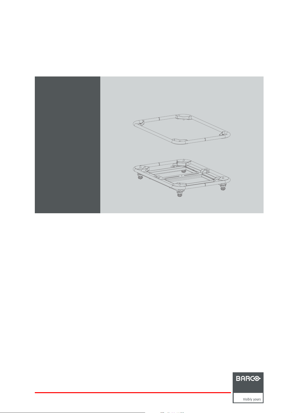
Top & Bottom Carry Handle
R5905106/00
28/06/2011
Installation manual
For HDX series
R9864060
R9864070
R9864080
Page 2

Barco nv Events
Noordlaan 5, B-8520 Kuurne
Phone: +32 56.36.82.11
Fax: +32 56.36.88.24
Support: www.barco.com/esupport
Visit us at the web: www.barco.com
Printed in Belgium
Page 3

Changes
Barco provides this manual ’as is’ without warranty of any kind, either expressed or implied, including but not limited to the implied warranties or merchantability and fitness for a particular purpose. Barco may m ake improvements and/or changes to the product(s) and/or the
program(s) desc ribed in this publication at any time without notice.
This publication could contain technical inaccuracies or typographical errors. Changes are periodically made to the information in this
publication; these changes are incorporated in new editions of this publication.
Copyright ©
All rights reserved. No part of this document may be copied, reproduced or translated. It shall not other
stored in a retrieval system without the prior written con sent of Barco.
wise be recorded, transmitted or
Disposal Information
This equipment has required the extraction and use of natural resources for its production. It may contain hazardous substances for health
and environment. In order to av oid the dissemination of those substances in the environment and to diminish the pressure on natural
resources, we encourage you to use the appropriate take-back systems. Those systems will reuse or recycle most of the materials of your
end of life equipment in a sound way.
The crossed-out wheeled bin symbol invites you to use those systems. If you need more information on the collection, reuse and recycling
systems, please contact your local or regional wa ste administrator. You can also contact us for more information on the environmental
performances of ou r products.
Trademarks
Brand and product names m entioned in this manual may be trademark
All brand and product names mentioned in this manual serve as comments or examples and are not to be understood as advertising for
the products or their manufacturers.
s, registered trademarks or copyrights of their respective holders.
Page 4

Page 5

Table of contents
TABLE OF CONTENTS
1. Introduction ............... ................ ................ ................ ................ ................ ......... 3
1.1 Top Carry Handle . . .................................................................................................................. 4
1.2 Bottom CarryHandle................................................................................................................ 5
1.3 Touring kit ............................................................................................................................ 6
2. Installation procedures........ ................ ................ ................ ................ ................ ... 7
2.1 Installing the Bottom Carry Handle ................................................................................................. 8
2.2 Removing the Bottom Carry Handle ................................................................................................ 10
2.3 Installing the Top Carry Handle .....................................................................................................12
2.4 Removing the Top Carry Handle ....................................................................................................13
2.5 Allowed projector positions..........................................................................................................14
2.6 Stacking projectors .................................................................................................................. 16
2.7 Suspending the projector from a truss ..............................................................................................18
2.8 Skewing the projector ............................................................................................................... 23
2.9 Inclinating and/or rotating the projector . . .. . ........................................................................................ 24
2.10 Aligning stacked projectors..........................................................................................................25
2.11 Dimensions ..........................................................................................................................26
R5905106 TOP & BOTTOM CARRY HANDLE 28/06/2011
1
Page 6

Table of contents
2 R5905106 TOP & BOTTOM CARRY HANDLE 28/06/2011
Page 7

1. Introduction
1. INTRODUCTION
Purpose of the Top & Bottom Carry Handles
The Top & Bottom Car ry Handles are exclusively designed for the Barco HDX series and can thus not be used on any other equipment.
About this manual
This manual is applicable for the following kits:
• Top Carry Handle
• Bottom Carry Handle
• Touring kit
Depending on which procedure you want to perform, a Top Carry Handle and/or Bottom Carry Handle is needed.
Overview
• Top Carry Handle
• Bottom Carry Handle
• Touring kit
R5905106 TOP & BOTTOM CARRY HANDLE 28/06/2011
3
Page 8
1. Introduction
1.1 Top Carry Handle
Order info & content of the kit
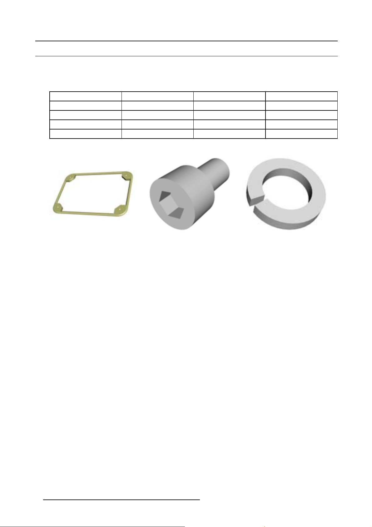
When ordering the Top Carry Handle for HDX series, refer to article number R9864060.
The table below gives an overview of the content of the kit.
Article number Description Quantity Image
R5905106 This installation manual 1
R870055 Frame 1 image 1-1
A566050 Screw (M10x16) 4 image 1-2
B3624221 Washer 4 image 1-3
Image 1-1 Image 1-2 Image 1-3
4 R5905106 TOP & BOTTOM CARRY HANDLE 28/06/2011
Page 9
1.2 Bottom Carry Handle
Order info & content of the kit
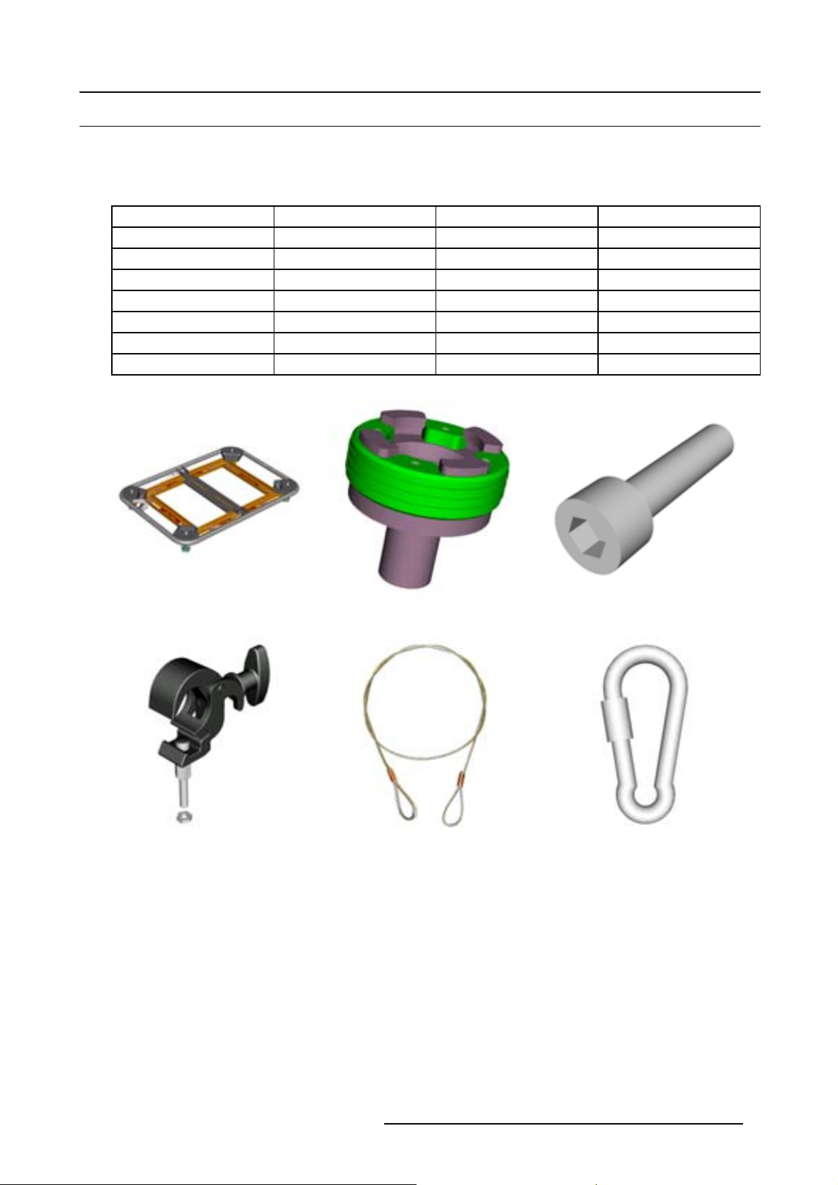
When ordering the Bottom Carry Handle for HDX s eries, refer to article number R9864070.
The table below gives an overview of the content of the kit.
Article number Description Quantity Image
R5905106 This installation manual 1
R870929 Frame 1 image 1-4
R856608 Stacking point 4 image 1-5
A576097 Screw (M10x40) 4 image 1-6
R870953 Clamp 4 image 1-7
B3612131 Safety cable 2 image 1-8
B362090 Snap hook 2 image 1-9
1. Introduction
Image 1-4 Image 1-5 Image 1-6
Image 1-7 Image 1-8 Image 1-9
R5905106 TOP & BOTTOM CARRY HANDLE 28/06/2011 5
Page 10

1. Introduction
1.3 Touring kit
Order info & content of the kit
When ordering the Touring kit for HDX series, refer to article number R9864080.
The table below gives an overview of the content of the kit.
Article num ber Description Quantity
R5905106 This installation manual 1
R9864060 Top Carry Handle (See "Top Carry
Handle", page 4 )
R9864070 Bottom Carry Handle (See "Bottom Carry
Handle", page 5 )
1
1
6 R5905106 TOP & BOTTOM CARRY HANDLE 28/06/2011
Page 11

2. INSTA LLATION PROCEDURES
Overview
• Installing the Bottom Carry Handle
• Removing the B ottom Carry Handle
• Installing the Top Carry Handle
• Removing the Top Carry Handle
• Allowed projector positions
•Stackingprojectors
• Suspending the projector from a truss
• Skewing the projector
• Inclinating and/or rotating the projector
• Aligning stacked projectors
• Dimensions
2. Installation procedures
R5905106 TOP & BOTTOM CARRY HANDLE 28/06/2011
7
Page 12

2. Installation procedures
2.1 Installing the Bottom Carry Handle
Necessary tools
17 mm open-end wrench
How to install the Bottom Carry Handle?
1. Turn the projector upside down and remove the 4 feet (reference 1, image 2-1) by turning them anticlockwise.
1
Image 2-1
2. Turn o ut the stacking points of the carry handle (reference 2, image 2-2) a few turns in order to create some space to be able to
install the m ounting bolts.
3. Position the Bottom Carry Handle on the projector so that the fixation holes (reference 3, image 2-2) match the holes in the
projector (reference 4, image 2-2).
Tip: Make sure the adjustment knob (reference 5, image 2-2) is positioned on the back of the projector.
3
5
3
2
Image 2-2
4. Se cure the B ottom Carry Handle by installing the 4 bolts (reference 6, image 2-3) and tighten the bolts.
4
3
4
8
R5905106 TOP & BOTTOM CARRY HANDLE 28/06/2011
Page 13

6
Image 2-3
5. B ring the stacking points back to their original position by turning them c lockwise.
2. Installation procedures
R5905106 TOP & BOTTOM CARRY HANDLE 28/06/2011
9
Page 14

2. Installation procedures
2.2 Removing the Bottom Carry Handle
How to remove the Bottom Carry Ha ndle?
1. R emov e the 4 bolts (reference 6, image 2-4).
6
Image 2-4
2. R emov e the Bottom Carry Handle from the projector (image 2-5).
Image 2-5
3. Install the 4 feet by turning them c
10
lockwise (im age 2-6).
R5905106 TOP & BOTTOM CARRY HANDLE 28/06/2011
Page 15

Image 2-6
2. Installation procedures
R5905106 TOP & BOTTOM CARRY HANDLE 28/06/2011 11
Page 16

2. Installation procedures
2.3 Installing the Top Carry Handle
Necessary tools
8 mm Allen wrench
How to install the Top Carry Handle?
1. Position the Top Carry Handle on top of the projector so that the fixation holes match the holes in the projector.
2. Turn in the 4 bolts (reference 1, image 2-7). Insert a washer between the bolt and the carry handle.
1
1
Image 2-7
12 R5905106 TOP & BOTTOM CARRY HANDLE 28/06/2011
Page 17

2.4 Removing the Top Carry Handle
Necessary tools
8 mm Allen wrench
How to remove the Top Carry Handle?
1. Turn out the 4 bolts (reference 1, image 2-8) and remove the 4 washers.
2. Installation procedures
1
1
Image 2-8
2. R emov e the Top Carry Handle from the projector.
R5905106 TOP & BOTTOM CARRY HANDLE 28/06/2011
13
Page 18

2. Installation procedures
2.5 Allowed projector positions
CAUTION: Using the projector in a disallowed position can cause premature lamp failure.
Which projector positions are allowed?
With both the Top Carry Handle and Bottom Carry Handle installed, the projector can be placed in several positions. However, not
all positions are allowed. The illustration below gives an overview (image 2-9).
Image 2-9
Checking the position using the built-in tilt sensor
The projector is equipped with a built-in sensor which can be read out to see if the projector is used in an allowed position.
Perform the following procedure to check if the projector position is allowed:
14
R5905106 TOP & BOTTOM CARRY HANDLE 28/06/2011
Page 19

1. Press Menu to activate the menus and select Service → Diagnosis → Tilt sensor.
Image 2-10
Image 2-11
2. Installation procedures
Image 2-12
2. Press ENTER to read out the tilt sensor.
Image 2-13
The rotation of the projector is visually displayed. Coordinates of the tilt sensor and the offset from the normal position are given in
the tilt sensor pane.
The status pane indicates if the projector is used w ith an allowed rotation.
R5905106 TOP & BOTTOM CARRY HANDLE 28/06/2011
15
Page 20

2. Installation procedures
2.6 Stacking projectors
The procedure below describes how to stack 2 projectors. The procedure to stack 3 projectors is analog.
WARNING: Never stack more than three (3) p rojectors. Failure to do so can cause serious injury o r death.
Necessary tools
8 mm Allen wrench
How to stack 2 projectors?
1. Install the Bottom Carry Handle on the projec tors you want to stack. See "Installing the Bottom Carry Handle", page 8 .
Note: If the stack is only used for a standing c on figur ation, the bottom projector doesn’t have to be equipped with a Bottom
Carry Handle.
2. Position 4 stacking points (reference 1, image 2-14) on top of the bo ttom projector. Install the 4 bolts and tighten.
1
Image 2-14
3. Position the top projector with the Bottom Carry Handle on the stacking points of the bottom projector.
16
R5905106 TOP & BOTTOM CARRY HANDLE 28/06/2011
Page 21

2. Installation procedures
Image 2-15
4. L ock the stacking points by rotating the ring a quarter turn clockwise while pushing it downwards until the ring it clicks in (image 2-16).
A B
Image 2-16
C D
R5905106 TOP & BOTTOM CARRY HANDLE 28/06/2011 17
Page 22

2. Installation procedures
2.7 Suspending the projector from a truss
WARNING: Never suspend more than two (2) projectors. Failure to do so can cause serious injury or death.
Introduction
A projector ca n be suspended from a truss using rigging clamps. When a Bottom Carry Handle is installed on the projector, 8 slots
are available to mount rigging clamps . 4 slots are longitudinally oriented (reference 1, image 2-17) and 4 slots are transversely
oriented (reference 2, image 2-17). Each slot contains a rigging point (reference 3, image 2-17) of which the position in the slot can
be adjusted depending on the truss the projec tor is being suspended from. The rigging clamps can be attached to those rigging
points, which allows an easy and fast physical setup of the projector in a hanging configuration.
3
2
1
Image 2-17
Necessary tools
• 17 mm open-end wrench
• 24 mm open-end wrench
How to suspend 1 projector from a truss?
1. M easure the center distance of the truss support bars as illustrated.
X mm
Image 2-18
2. L oosen the nuts of the rigging points (reference 1, image 2-19) and slide them on there place according to the measured center
distance.
Tighten the nuts of the rigging points.
Warning: Make sure the rigging points are symmetrically around the center of the Bottom Carry Handle to ensure the balance
Warning: Make sure the rigging po
of the hanging projector.
ints are tightened after adjustment.
18
R5905106 TOP & BOTTOM CARRY HANDLE 28/06/2011
Page 23

2. Installation procedures
X mm
1
1
Image 2-19
3. M ount the rigging clamps on the rigging points:
a) Screw the nut (reference 2, imag e 2-20) on the spacer (reference 3, image 2-20) to the desired height.
b) Install the spacer in the rigging point by turning it clockwise until the nut and the rigging po int meet.
Warning: Make sure that the spacers are sc rewed in for minimum 2 cm in the rigging points. Failure to do so can cause the
Warning: Always use 4 r igging points when suspending a projector.
projector to fall down.
3
2
Image 2-20
4. Position the projector under the truss and lower the truss u ntil the truss support bars are nearby the rigging clamps.
5. L ift the projector and hook the 4 rigging clamps over the truss support bars.
R5905106 TOP & BOTTOM CARRY HANDLE 28/06/2011
19
Page 24

2. Installation procedures
Image 2-21
6. L ock the 4 rigging clamps by turning the fixation knob clockwise.
Image 2-22
7. Install the 2 safety cables. Wind them around the carry handle and the truss (push the hook through the loop and then ar ound
the trus s). Ensure that the play is maximum 20 cm. If necessary, wind the cable a few times around the truss before clasping
the safety hook around the cable.
20
R5905106 TOP & BOTTOM CARRY HANDLE 28/06/2011
Page 25

2. Installation procedures
Image 2-23
8. L ift up the t russ with projector to the desired height.
Warning: Make sure the safety cable is installed with a minimum of play, so that the projector can only fall down for maximum
20 cm. If necessary, wind the cable a few times around the truss before clasping the safety hook around the cable.
WARNING: Never suspend more than two (2) projectors. Failure to do so can cause serious injury or death.
How to suspend 2 projectors from a truss?
1. S tack the 2 projectors as described in "Stacking projectors", page 16.
2. Turn the stack upside down.
Install 2 safety cables around both Bottom Carry Handles by performing the following p rocedure:
a) Install the safety cables around the Bottom Carry Handle of the bottom pr ojector. Push the safety hooks t hrough the loops.
b) Install the other end of the safety cables around the Bottom Carry Handle of the top projector and clasp the s afety hooks
around the c ables as illustrated.
Warning: Make sure the safety cables are installed with a minimum of play, so that the projector can only fall down for maximum
20 cm. If necessary, wind the cables a few times around the carry handle tubes before clasping the safety hooks
around the cables.
R5905106 TOP & BOTTOM CARRY HANDLE 28/06/2011
21
Page 26

2. Installation procedures
Image 2-24
Security cables, mount
Warning: Always use 2 safety cables to secure a stacked projector in a hanging configuration.
3. Suspen d the s tack from the truss as described in "Suspending the projector from a truss", page 18.
22
R5905106 TOP & BOTTOM CARRY HANDLE 28/06/2011
Page 27

2.8 Skewing the projector
How to skew the projector?
1. Turn the adjustment knob c lockwise or anticlockwise to skew the projector as illustrated.
Image 2-25
2. Installation procedures
R5905106 TOP & BOTTOM CARRY HANDLE 28/06/2011 23
Page 28

2. Installation procedures
2.9 Inclinating and/or rotating the projector
How to inclinate and/or rotate the projector?
1. Turn the projector feet in or out to inclinate and/or rotate the projector as needed.
Image 2-26
24 R5905106 TOP & BOTTOM CARRY HANDLE 28/06/2011
Page 29

2. Installation procedures
2.10 Aligning stacked projectors
How to align stacked projectors?
1. Project a hatch pattern with the reference projector.
Note: In case of a table mount confi guration the reference projector is the lowest projector and in case of a hanging configuration
the reference projector is the uppermost projector.
2. M ake sure the hatch pattern projected by the reference projector is sharp and has a perfect rectangle outline. If this is not the
case, readjust the reference projec tor before aligning the other stacked projector(s) with the reference hatch pattern.
3. Project the same hatch pattern with the other projector in the stack.
Tip: Use a white colored hatch pattern for the reference projector and e.g. green colored for the stacked projector. This
makes it easier t o see the difference between both hatch patterns projected.
4. If necessary, adjust the rotation of the stacked projector w ith respect to the reference projector. See "Inclinating and/or rotating
the projector", page 24.
5. If necessary, adjust the inclination of the stacked projector with respect to the reference projector. See "Inclinating and/or rotating
the projector", page 24.
6. If necessary, adjust the skew of the stacked projector with respect to the reference projector. See "Skewing the projector", page
23.
7. S hift the hatch pattern horizontally and vertically until the outline of the hatch pattern is most symmetrically placed with respect
to the reference hatch pattern.
Note: Note that the “Shift” function is motorized, which means that you have to ac cess the projector software, via the local
keypad or remote control unit, to operate the “Shift” function.
Shift
Image 2-27
Stacked projectors, shift
8. Zoom the hatch pattern in or out until the outline of the hatch pattern matches exactly the outline of the reference hatch pa ttern.
Note: Note that the “Zoom” function is motorized, which means that you have to access the projector software, via the local
keypad or remote control unit, to operate the “Zoom” function.
Zoom
Image 2-28
Stacked projector, zoom
9. If necessary, repeat this procedure starting from step 3 until the hatch pattern of the stacked projector is perfectly aligned with
the hatch pattern of the reference projector.
In cas e of a triple stacked table mou
than the projector in the middle and finally the upper projector.
nt configuration, adjust and align fi rst the bottom projector (reference),
R5905106 TOP & BOTTOM CARRY HANDLE 28/06/2011 25
Page 30

2. Installation procedures
2.11 Dimensions
Top Carry Handle
Image 2-29
Dimensions give n in millimeters
685
575
Bottom Carry Handle
435
Image 2-30
Dimensions give n in millimeters
685
200 174174
825
96
160
96
575
26 R5905106 TOP & BOTTOM CARRY HANDLE 28/06/2011
 Loading...