

Page 1
HDQ 4K35
User and Installation manual
R5905823/04
30/11/2015
Page 2

Barco NV
President Kennedypark 35, 8500 Kortrijk, Belgium
Phone: +32 56.36.82.11
Fax: +32 56.36.883.86
Support: www.barco.com/en/support
Visit us at the web: www.barco.com
Printed in Belgium
Page 3

Copyright ©
All rights reserved. No part of this document may be copied, reproduced or translated. It shall not otherwise be recorded, transmitted or
stored in a retrieval system without the prior written consent of Barco.
EN55022/CISPR22 Class A ITE (Information Technology Equipment)
Class A ITE is a category of all other ITE which satisfies the class A ITE limits but not the class B IT E limits. S uch equipm ent should not
be restricted in its sale but the following warning shall be included in the instructions for use:
Warning : This is a class A product. In a domestic environment this product may cause radio interference in which case the user may be
required to take adequate measures.
Federal Communications Commission (FCC Statement)
This equipment has been tested and found to comply with the limits for a class A digital device, pursuant to Part 15 of the FCC rules.
These limits are designed to provide reasonable protection against harmful interference when the equipment is operated in a commercial
environment. This equipment generates, uses, and can radiate radio f requency energy and , if not installed and used in a ccordance with
the instruction manual, may c ause harmful interference to radio communications. Oper ation of this equipment in a residential area may
cause harmful interference, in which case t he user will be responsible for correcting any interference at his own expense
Changes or modifications not expressly approved by the party responsible for c ompliance could void the user’s authority to operate the
equipment
Trademarks
Brand and product names mentioned in this manual may be trademarks, registered trademarks or copyrights of their respective holders.
All brand and product names mentioned in this manual serve as commen ts or examples and are not to be understood as advertising for
the products or their manufacturers.
Changes
Barco provides this manual ’as is’ without warranty of any kind, eit
ranties or merchantability and fitness for a particular purpose. Barco m ay make improvements and/or changes to the product(s) and/or the
program(s) described in this publication at any time without notice.
This publication could contain technical inaccuracies or typographical errors. Changes are periodically made to the information in this
publication; these changes are incorporated in new editions of this publication.
The latest edition of Barco manuals can be dow nloaded from the Barco web site w
h
ttps://www.barco.com/en/signin.
her expressed or implied, including but not limited to the implied war-
ww.barco.com or from the secured B arco web site
Guarantee and Compensation
Barco provides a guara ntee relating to perfect manufacturing as part of the legally stipulated terms of guarantee. On receipt, the purchaser
must immediately inspect a ll delivered goods for damage incurred during transport, as well as for material and manufacturing faults Barco
must be informed immediately in writing of any complaints.
The period of gu arantee begins on the date of transfer of risks, in the case of special systems and software on the date of commissioning,
at latest 30 days after the transfer of risks. I
at its own discretion w ithin an appropriate period. If this m easure proves to be impossible or uns ucce ssful, the purchaser can deman d a
reduction in the purchase pr ice or cancellation of the contract. All other claims, in particular th ose relating to compensation for direct or
indirect damage, and also damage attribut
of the system or independent service, will be deemed invalid provided the damage is not proven to be attributed to the absence of properties
guaranteed in writing or due to the intent or gross negligence or part of Barco.
If the purchaser or a third party carries out modifications or repairs o n goods delivered by Barco, or if the goods are handled incorrectly,
in particular if the systems are operated incorrectly or if, after the transfer of risks, the goods a re subject to influences not agreed upon in
the contract, all guarantee claims of the purchaser will be rendered invalid. Not included in the guarantee coverage are system failures
which are attributed to programs or s pecial electronic circuitry provided by the purchaser, e.g. interfaces. Normal wear as well as normal
maintenance are not subject to the guarantee provided by Barco either.
The environmental conditions as well as the servicing and maintenance regulations specified in this manual must be complied with by the
customer.
n the event of justified notice of complaint, Barco can repair the fault or provide a replacement
ed to the operation of software as well as to other services provided by Barco, being a component
Page 4

Page 5

Table of contents
TABLE OF CONTENTS
1. Safety................................................................................................................. 3
1.1 General considerations ............................................................................................................... 4
1.2 Important safety instructions ......................................................................................................... 5
2. General....... ................ ................ ................ ................ ................ ................ ........ 9
2.1 Installation requirements . . . ......................................................................................................... 10
2.2 Unpacking the projector ............................................................................................................. 11
2.3 Initial inspection......................................................................................................................14
2.4 Airinlets and outlets................................................................................................................. 15
2.5 Installation process overview........................................................................................................16
3. Physical installation ..............................................................................................17
3.1 Installation of the Lamp House ...................................................................................................... 18
3.2 Access to the power connection . . .................................................................................................. 19
3.3 Power input setup of the H DQ 4K35 ................................................................................................ 20
3.4 Connecting the projector with the power net ....................................................................................... 22
3.5 Connecting a UPS to the projector electronics . . ...................................................................................23
3.6 Landscape and portrait mode ....................................................................................................... 25
3.7 Stacking multiple projectors......................................................................................................... 27
3.8 Adjusting the multifunctional frame .................................................................................................30
3.9 Aligning the projected image on the screen ........................................................................................32
3.10 Aligning stacked projectors..........................................................................................................34
4. Lenses & Lens Holder ............... .................. ................ ................ ................ ...........37
4.1 Available lenses .....................................................................................................................38
4.2 Lens selection ....................................................................................................................... 40
4.3 Lens installation ..................................................................................................................... 41
4.4 Lens removal ........................................................................................................................ 43
4.5 Installing the lens fixation mechanism .............................................................................................. 44
4.6 Removing the lens fixation mechanism . .. . . ........................................................................................45
4.7 Lens shift, zoom & focus . .. .........................................................................................................46
4.8 Additional vertical shift of the Lens Holder. . ........................................................................................47
4.9 Scheimpflug adjustment............................................................................................................. 48
4.10 Fixation of the Lens Holder front plate ..............................................................................................52
5. Input and Communication .. ................ ................ ................ ................ .................. ...55
5.1 Introduction .......................................................................................................................... 56
5.2 Local keypad of the HDQ projector ................................................................................................57
5.3 Communication ports of the HDQ projector ........................................................................................58
5.4 Source input ports of the Barco HDQ 4K35 pr ojector . . . ...........................................................................60
5.5 ICMP status LEDs................................................................................................................... 63
5.6 ICMP reset...........................................................................................................................64
6. Starting up..........................................................................................................65
6.1 Switching ON the HDQ ..............................................................................................................67
6.2 Switching OFF the HDQ.............................................................................................................68
7. Maintenance....... ................ ................ ................ ................ ................ ................ .69
7.1 Cleaning the front dust fi lter......................................................................................................... 70
7.2 Cleaning the bottom dust filters .....................................................................................................71
7.3 Cleaning the lens . .. .................................................................................................................72
7.4 Cleaning the exterior of the projector ............................................................................................... 73
7.5 Checking cooling liquid level ........................................................................................................74
7.6 Topping up the cooling liquid reservoir..............................................................................................75
7.7 Removal of the Lamp House........................................................................................................77
7.8 Realignment of the lamp in its reflector.............................................................................................78
7.9 Authorization to clear security warning on the projector ...........................................................................79
8. Removal and installation of the projector covers .... ................ ................ ................ .......81
8.1 Removal of the lamp cover.......................................................................................................... 82
8.2 Installation of the lamp cover........................................................................................................ 83
8.3 Removal of the input cover. ......................................................................................................... 84
8.4 Installation of the input cover........................................................................................................85
8.5 Removal of the front cover .......................................................................................................... 86
8.6 Installation of the frontcover ........................................................................................................ 87
8.7 Removal of the back cover..........................................................................................................88
8.8 Installation of the back cover........................................................................................................ 89
8.9 Removal of the left cover............................................................................................................ 90
8.10 Installation of the left cover.......................................................................................................... 91
A. Dimensions and specifications ..................................................................................93
A.1 Dimensions of the Barco HDQ 4K35................................................................................................ 95
A.2 Specifications of the Barco HDQ 4K35 ............................................................................................. 96
R5905823 HDQ 4K35 30/11/2015
1
Page 6

Table of contents
A.3 Technical Regulations ...............................................................................................................98
B. Environmental information .. ................ .................. ................ ................ ................ ...99
B.1 Disposal information................................................................................................................100
B.2 RoHS compliance ..................................................................................................................101
B.3 Production address . ................................................................................................................102
B.4 Importers contact information ......................................................................................................103
Glossary ...... ................ ................ ................ .................. ................ ................ ....... 105
Index............. ................ ................ ................ ................ ................ .................. ..... 107
2 R5905823 HDQ 4K35 30/11/2015
Page 7

1. SAFETY
About this chapter
Read this chapter attentively. It co ntains important information to prevent personal injury while installing and us ing a Barco HDQ
4K35. Furthermore, it includes several cautions to prevent damage to the HDQ 4K35. Ensure that you understand and follow all
safety guidelines, safety instructions and war nings mentioned in this chapter before installing your HDQ 4K35. After this chapter,
additional “warnings” and “cautions” are given depending on the installation procedure. Read and follow these “warnings” and “cautions” as well.
1. Safety
R5905823 HDQ 4K35 30/11/2015
3
Page 8
1. Safety
1.1 General considerations
WARNING: E nsure you understand and follow a ll the safety guidelines, safety instructions, warnings and
cautions mentioned in this manual.
WARNING: Be aware of su spended loads.
WARNING: Wear a hard hat to reduce the risk of personal injury.
WARNING: Be careful while working with heavy loads.
WARNING: Mind your fingers while working with heavy loads.
CAUTION: High p ressure lamp may explode if improperly handled.
General safety instructions
• Before operating t his equipment please read this manual thoroughly and retain it for future reference.
• Installation and preliminary a djustments s hould be performed by qualified Barco personnel o r by authorized Barco service dealers.
• All warnings on the projector and in the documentation m anuals s hould be adhered to.
• All instructions for operating and use of this equipment must be followed precisely.
• All local installation codes should be adhered to.
Notice on safety
This equipment is built in accordance with the requirements of the international safety standards IEC60950-1, EN60950-1,
UL60950-1 and CAN/CSA C22.2 No.60950-1, w hich are the safety standards of information technology equipment including
electrical business equipmen t. These s afety standards
materials and insulation, in order to protect the user or operator against risk of electric shock and energy hazard and having access
to live parts. Safety standards also impose limits to the internal and external temperature rises, radiation levels, mechanical stability
and strength, enclosure construction and protecti
safety of the equipm ent to the user even when the equipment’s normal operation fails.
impose important requirements on the use of s afety critical components,
on against the risk of fire. Simulated single fault con dition testing ensures the
Users definition
Throughout this manual, the term SE RVICE P ERS ONNEL refers to persons having appropriate technical training and experience
necessary to be knowledgeable of potential hazards to which they are exposed (including, but not limited to HIGH VOLTAGE ELECTRIC and ELECTRONIC CIRCUITRY and HIGH BR IGHTNESS PROJECTORS) in performing a task, and of measures to minimize
the potential risk to them selves or other persons. The term USER and OPERATOR refers to any person other than SERVICE PERSONNEL, AUTHORIZED to ope rate professional projection systems.
A Barco H DQ 4K35 is intended "FOR PROFESSIONAL USE ONLY" by AUTH O RIZE D PERSONNEL familiar with potential hazards
associated with high voltage, high intensity light beams, ultraviolet exposure and high temperatures generated by the lamp and
associated c ircuits. Only qualified SERVICE PERSONNEL, knowledgeable of such risks, are allowed to perform service functions
inside the product enclosure.
4
R5905823 HDQ 4K35 30/11/2015
Page 9

1.2 Important safety instructions
To prevent the risk of electrical shock
• This projector should be operated from an AC power source. Ensure that the mains voltage and capacity matches the projector
electrical ratings.
• Installation according to the local electrical code and regulations by qualified technical personnel only.
• This product is e quipped with a five-terminal barrier s trip for the connection of a 3W +N+P E or 3W+PE three phase power
system. If you are unable t o install the AC Requirements, contact your electrician. Do not defeat the purpose of the grounding.
• The cross-sectional area of the conductors in the power supply cord shall not be less than 4 mm
The cross-sectional area of the UPS inlet cord and external fan power cord shall be not less than 0.75 mm² or AWG 18.
• The electronics of the projector (UPS INLET) must be powered either from a suitable UPS unit or from the po wer outlet socket
(UPS OUTLET) provided on the projector. An adapted short power cord (2-pole 3-wire grounding) is added to the projector
accessories to loop through the power from UPS OUTLET to UPS INLET.
• The provided power output soc ket (UPS OUTLET) on the projector may only be used to provide power to the projector electronics. Never connect other devices to this power output socket.
• The building installation has to be provided with a circuit breaker of max. 40A to protect the comp lete unit.
• A readily accessible disconnect device must be incorporated externally to the equipmen t for rem oval o f the power to the projector mains terminals.
• Disconnect the power to the projector mains terminals and unplug the power cord at UPS INLET for removal of all power from
the projector.
• Warning: High leakage current. Earth connection essential before connecting supply.
• Do not allow anything to rest on the power cord. Do not locate this projector where persons will walk on the cord.
• Do not operate the projector with a damaged cord or if the projector has been dropped or damaged - until it has been examined
and approved for operation by a qualified service technician.
• Position the cord so that it will not be tripped over, pulled, or contact hot surfaces.
• If an extension cord is necessary, a cord with a current rating at least equal to that of the projector should be used. A cord rated
for less amperage than the projector may overheat.
• Never push objects of any kind into this pr ojector through cabinet slots as they m ay touch dangerous voltage points or short
circuit parts that could result in a risk of fire or electrical shock.
• Do not expose this projector to rain or moisture.
• Do not immerse or expose this projector in water or other liquids.
• Do not spill liquid of any kind on this projector.
• Should any liquid or solid object fall into the cabinet, unplug the set and have it chec ked by qualified service personnel before
resuming operations.
• Do not disassemble this projector, always take it to a trained service person w hen service or repair work is required.
• Do not use an accessory attachment which is not recommended by the manufacturer.
• Lightning - For added protection for this video product during a lightning
long periods of time, remove all powe r from the projector. This will prevent damage to the projector due to lightning and AC
power-line surges.
storm, or when it is left unattended and unused for
2
or AWG 10.
1. Safety
R5905823 HDQ 4K35 30/11/2015
5
Page 10

1. Safety
To prevent personal injury
• Isolate electrically before replacing the lamp or lamp house. Caution: Hot lamp (house).
• Caution: High pressure lam p may explode if improperly handled. Refer se rvicing to qualified service personnel.
• To pre vent injury a nd physical damage, always read this manual and all labels on the system before inserting the lamp casing,
powering the projector or adjusting the projector.
• It is forbidden to lift up the projector with manpower, use a hois ting tool instead. Do not underestimate the weight of the projector.
The projector weights ±210 kg (±462 lb.).
• To prevent injury, ensure that the lens, exhausting system and all cover plates are correctly installed. See installation instructions.
• Ensure safe fi xation of the projector lens. The lens fixation mechanism must be installed. See installation instructions.
• Warning: high intensity light beam. NEVER look into the lens ! High luminance c ould result in damage to the eye.
• Warning: extremely high brightness lam ps: T his projector uses extremely high brightness lamps. Never attempt to look
directly into the lens or at the lamp. If the projection distance is less than 6 meter, any person needs to be at least 4 meters
away from the projected image. Avoid close ran ge reflection of the projected image on any reflecting surface (such as glass,
metal, …) . When operating the projector, we strongly recommend wearing suitable sa fety glasses.
• Before attempting to remove any of the pr ojector’s covers, disconnect the power to the projector mains terminals and unplug
the power cord at UPS INLET for removal of all power from the projector.
• The projector m ay not be powered when the exhaust box on top of the projector is removed. Before attempting to remove the
exhaust box, disconnect the power to the projector m ains terminals and unplug the power cord at UPS INLET for removal of all
power from the projector.
• When r equired to remove all power from the projector, to access parts inside, always disconnect the power to the projector
mains terminals and unplug the power cord at UPS INLET.
• Do not place this equipmen t on an unstable cart, stand, or table. The product may fall, causing serious damage to it and
possible injury to the user.
• Never stack more than three (3) HDQ projectors in a standing configuration (table mount) and never stack more than two ( 2)
HDQ projectors in a hanging confi guration (ceiling mount).
• When u sing the projector in a hanging configuration (ceiling mount), always mount 2 safety cables on the projector frame. See
installation instructions for the correct use of these cables.
• Always check the safety cables for visible damage before operating the projector. If the safety cables are damaged, they must
be replaced with new ones.
• It is hazardous to operate without lens or shield. Lenses, shields or ultra violet screens shall be changed if they have become
visibly damaged to such an extent that their effectiveness is impaired. For example by cracks or deep s cratches.
• Warning: Protection from ultraviolet radiation: D o not look directly in the light beam. The lamp contained in this product is
an intense source of light and heat. One component of the light emitted from this lamp is ultraviolet light. Potential eye and s kin
hazards are present when the lamp is energized due to ultraviolet radiation. Avoid unnecessary exposure. P rotect y ourself and
your employees by ma king them aware of the hazards and how to protect themselves. Protecting the skin can be accomplished
by wearing tightly wov en garments and glov es. Protecting the eyes from UV can be accomplished by wearing safety glasses
that are designed to provide UV protection. In addition to the UV, the visible light from the lamp is intense and should also be
considered when choosing protective eye wear.
• Exposure to U V radiation: Some medications are known to m ake individuals extra sens itive to UV radiation. The American
Conference of Gov ernmental Industrial Hygienists (ACG
less than 0,1 micro-watts per square centimeters of effective UV radiation. An evaluation of the workplace is advised to assure
employees are not exposed to cumulative radiation levels exceeding these government guidelines.
• Cooling liquid circuit. The projector contains a cooling circuit filled with Blue antifreeze diluted (1/3 ethanediol – 2/3 Demi
water).
When the cooling circuit leaks, switch off the device and contact a service technician.
The liquid is not for household use. Keep out of reach of children. Harmful by oral intake. Avoid exposure to pregnant women.
Avoid contact with eyes , sk in and clothing. Avoid inhale of the noxious fumes.
IH) recommends o ccupational UV exposure for an-8 hour day to be
WARNING: E xposu re to hazardous m ovin g parts when the exhaust box is removed. Always disconnect the
power to the projector mains terminals and unplug the power cord at the UP S INLET for removal of all power
from the projector before removing the exhaust box.
WARNING: Exposure to high luminance and UV
nect the power to the projector mains terminals and unplug the power cord at the UPS INLET for removal of
all p ow er from the projector before removing the exhaust box.
radiation when the exhaust box is removed. Always discon-
WARNING: The complete exhaust box is very hot w h en the projector is on. To avoid burns, let the projector
cool down for at least 15 minutes before touching the exhaust box.
6 R5905823 HDQ 4K35 30/11/2015
Page 11

1. Safety
To prevent fire hazard
• Do not place flamma ble or combustible materials near the projector!
• Barco large screen projection products are designed and manufactured to meet the most stringent safety regulations. This
projector radiates heat on its external surfaces and from v entilation ducts during normal operation, which is both normal and
safe. E xpo sing flammable or combustible materials into close proximity of this projector c ould result in the spontaneous ignition
of that material, resulting in a fire. For this reason, it is absolutely necessary to leave an “exclusion zone” around all external
surfaces of the projector whereby no flammable or combustible materials are present. Th e ex clusion zone must be not less than
40 cm (16”) for all DLP projectors. The exclusion zone on the lens side must be at least 5 m. Do not c ove
r the projector or the
lens with any material while the projector is in operation. Keep flammable and combustible materials away from the projector at
all times. Mount the projector in a well ventilated area away from source s of ignition and out of direct sun light. Never expose
the projector to rain or moisture. In the event of fire, use sand, CO
electrical fire. Always have service per formed on this projector by authorized Barco service personnel. Alway s insist on genuine
or dry powder fire extingu
2
ishers. Never use wate r on an
Barco replacement parts. Never use non-Barco replacement parts as they may degrade the safety of this projector.
• Slots and openings in this equipm ent are provided for ventilation. To ensure reliable operation of the projector and to protect
it from overheating, these openings must not be blocked or covered. The openings should never be blocked by placing the
projector too close to walls, or other similar surface. This projector s hould never be placed near or over a radiator or heat
register. This p rojector should not be placed in a built-in installation or enclosure unless proper ventilation is provided.
• Projection rooms must be well ventilated or cooled in order to avoid build up of heat.
• Let the projector cool completely before storing. Remove cord from the projector when storing.
• Heat sensitive materials should not be placed in the path of the exhausted air or on the lam
p hous e.
• When the projector is used in portrait mode, the air outlet is positioned towards the floor. That’s why the floor covering can
become very hot and must be resistant to a temperature of 90 °C (194 °F).
To prevent projector damage
• This projector has been designed for use with a specific lamp (house) type. See installation instructions for its correct type.
•Theairfilters of the projector must be cleaned or replaced on a regular basis (a "clean" booth would be monthly-minimu m).
Neglecting this could result in disrupting the air flow inside th
projector shutting down during operation.
• The projector must a lways be installed in a manner which ens ures free flow of air into its air inlets and unimpeded evacuation
of the hot air from its cooling system.
• In order to ensure that correct airfl ow is maintained, and that the projector complies with Electromagnetic Compatibility (E MC)
and safety requirements, it should always be operated with all of it’s covers in place.
• Slots and openings in the cabinet are provided for ventilation. To ensure reliable operation of the product and to protect it from
overheating, these openings must not be blocked or covered. The openings should never be blocked by placing the product
on a bed, sofa, rug, or other similar surface. This product should never be placed near or over a radiator or heat register. The
device should not be placed in a built-in installation or enclosure unless proper ventilation is provided.
• Ensure that nothing can be spilled on, or dropped inside the projector. If this does happen, switch off and remove all power
from the projector. Do not operate the projector again until it has been checked by qualified s ervice personnel.
• Do not block the projector cooling fans or free air movement aroun d the projector. Lo ose papers or other objects may not be
nearer to the projector than 10 cm (4") on any side.
• Do not use this equipment near water.
• Proper operation of the cooling circuit c an only be guaranteed in the allowed projector positions. It is not allowed to use the
projector in another position. See installation instructions for correct installation.
• Special care for Laser Beams: Special care should be used when DLP projectors are us ed in the same room as high power
laser equipment. D irect or indirect hitting of a
laser beam on to the lens can severely damage the D igital Mirror Devices
which case there is a loss of warranty.
• Never place the projector in direct sun light. Sun light on the lens can severely damage the Digital Mirror Devices
case there is a loss of warranty.
• Save the original shipping carton and packing material. They will c ome in handy if you ever have to ship y our equipment. For
maximum protection, repack your set as it was originally packed at the factory.
• Disconnect the power to the projector mains terminals and unplug the power cord at UPS INLET before cleaning. Do not use
liquid cleaners or aerosol cleaners. Use a d amp cloth for cleaning. Nev er use strong solvents, such as thinner or benzine, or
abrasive cleaners, since these will damage the cabinet. Stubborn stains may be removed with a cloth lightly dampened with
mild detergent solution.
• To ensure the highes t optical performance and resolution, the projection lenses are specially treated with an anti-reflective
coating, therefore, avoid touching the lens. To remove dust on the lens, use a soft dry c loth. Do not use a damp cloth, detergent
solution, or thinner.
• Rated maximum ambient temperature, t
=35°C(95°F).
a
• The lamp house shall be replaced if it has become damaged or thermally deformed.
e projector, causing ov erheating. Overheating may lead to the
TM
TM
in which
in
R5905823 HDQ 4K35 30/11/2015
7
Page 12
1. Safety
On servicing
• Do not attempt to service this product yourself, as opening or rem oving covers may expose you to dangerous voltage potentials
and risk of electric shock.
• Refer all servicing to qualified service personnel.
• Attempts to alter the factory-set internal controls or to change other control settings not specially discussed in this manual can
lead to permanent damage to the projector and cancellation of the warranty.
• Remove all po wer from the projector and refer servicing to qualified service technicians under the following conditions:
- When the power cord or plug is da maged or frayed.
- If liquid has been spilled into the equipment.
- If the product has been exposed to rain or water.
- If the p roduct does not operate normally wh en the operating instructions are followed. Adjust only those controls that are
covered by the operating instructions since improper adjustment of the other controls may result in damage and will often
require extensive work by a qualified technician to restore the product to normal operation.
- If the product has been dropped or the cabinet has been damaged.
- If the product exhibits a distinct change in performance, indicating a need for service.
• Replacement pa rts: When replacement parts are required, be sure the s ervice technician has used original B arco replacement
parts or authorized replacement parts whic h have the same characteristics as the Barco original part. Unauthorized substitutions m ay result in degraded performance and reliability, fire, electric shock or other h azards. Unauthorized substitutions may
void warranty.
• Safety check: Upon completion of any service or repairs to this projector, ask the service technician to perform safety checks
to determine that the product is in proper operating condition.
• Possible explosion hazard: A lways keep in mind the caution below:
CAUTION: Xeno n co mp act arc lamps are highly pressurized. When ignited, the normal operating temperature
of the bulb increases the pressure to a level at which the bulb may explode if not handled in strict accordance
to the manufacturer’s instructions. The bulb is stable at room temperature, but may still explode if dropped or
otherwise mishandled. Whenever the lamp house, containing a xenon lamp, has to be dismantled or whenever
the protective container or cloth has to be removed from the xenon lamp, authorized protective clothing M U ST
be wo r n!
Authorized protective clothing for xenon lamp handling
WARNING: Always we ar face protection (full face shield) wh en handling xenon lamps.
WARNING: Always wear protective clothing (welder’s jacket) when handling xenon lamps.
WARNING: Always wear clean leather gloves with wrist protectors when handling xenon lamps.
To prevent battery explosion
• Danger of explosion if battery is incorrectly installed.
• Replace only with the same or equivalent type recommended by the manufacturer.
• For disposal of used batteries, always consult federal, state, local and provincial hazardous waste disposal r ules and regulations
to ensure proper disposal.
8
R5905823 HDQ 4K35 30/11/2015
Page 13
2. GENERAL
About this chapter
Read this chapter before ins talling your Barco HDQ 4K35. It contains important information concerning installation requirements for
the HDQ 4K 35, such as minimum and maximum allowed ambient temperature, humidity conditions, required safety area around the
installed projector, required power net, etc.
Furthermore, careful consideration of things such as image size, ambient light level, projector placement and type of screen to use
are critical to the optimum use of the projection system.
Barco provides a guarantee relating to perfect manufacturing as part of the legally stipulated terms of guarantee. Observing the s pecifi cation mentioned in this chapter is critical for projector performance. Neglecting
this can result in loss of warranty.
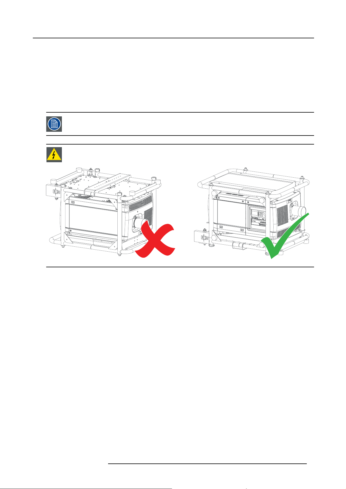
WARNING: Never transport the HDQ projector in an u pside down p osition. Failure to do so can cause damage
to t he frame. This can cause the frame to break and the projector to fall dow n .
2. General
Image 2-1
Overview
• Installation requirements
• Unpacking the projector
• Initial inspection
• Air inlets and outlets
• Installation process overview
R5905823 HDQ 4K35 30/11/2015
9
Page 14

2. General
2.1 Installation requirements
Environment conditions
Table below summ arizes the physical environment in which the HDQ may be safely ope rated or stored.
Environment Operating Non-Operating
Ambient Temperature 10 °C (50 °F) to 35 °C (95 °F) -15°C (5°F) to 60°C (140°F)
Humidity 5% to 85% R H Non-condensed 5% to 95% RH Non -Condensed
Altitude -60 (-197Ft) to 3000m (9843Ft) -60 (-197Ft) to 10000m (32810Ft)
Let the projector acclimatise after unpacking. Neglecting this may result in a startup failure of the
cessor Unit.
Light Pro-
Cooling requirements
The projector is fan cooled and must be installed with sufficient space around the projector he ad, minimum 20 cm (8”) to ensure
sufficient air flow. It should be us ed in an area where the ambient temperature, as measured at the projector air inlet , does not
exceed +35°C (+95°F).
For an ov erview of all air inlets and outlets of the projector, see "Air inlets and outlets", page 15.
Clean air environment
A projector mus t always be m ounted in a mann er which ensures the free flow of clean air into the projectors ventilation inlets. For
installations in environments where the projector is subject to airborne contaminants such as that produced by smoke machines or
similar (these deposit a thin layer of greasy residue upon the projectors internal optics and imaging electronic surfaces, degrading
performance), then it is highly advisable and desirable to have this contamination removed prior to it reaching the projectors clean
air supply. Devices or structures to extract or shield c ontaminated air well away from the projector are a prerequisite, if this is not a
feasible solution then measures to relocate the projector to a clean air environment should be considered.
Only ever use the manufacturer’s recommended cleaning kit which has been specifically designed for cleaning optical p arts, never
use industrial strength cleaners on the projector ’s optics as these will degrade optical coatings and damage sensitive optoelectronics
components. Failure to take suitable pr ecautions to protect the projector from the effects of persistent and prolonged air contaminants will culminate in extensive and irreversible ingrained optical damage. At this stage cleaning of the internal optical units will
be noneffective and impracticable. Damage of this nature is under no circumstances covered under the manufacturer’s warranty
and may deem the warranty null and void. In such a case the client shall be held solely responsible for all costs incurred during any
repair. It is the clients r espons ibility to ensure at all times that the projector is protected from the harmful effects of hostile airborne
particles in the environment of the projector. The manufacturer reserves the right to refuse repair if a projector has be en subject to
knowingly neglect, abandon or improper use.
Main Power requirements
The HD Q 4K35 operates from a nom inal 230/4
switched internally between a star connection to a delta connection or vice versa. See "P ower input setup of the HDQ 4K35", page
20.
For a 3W+N+PE system, 400V is measured between the lines, 230V is measured between the lines and the neutral.
For a 3W+PE system, 208V is measured between the lines.
The powe r cord required to connect the projector with the power net is not delivered with the projector. It is the responsibility of the
customer to provide the correct type of power cord.
The cross-sectional area of the conductors in the power supply cord shall not be less than 4 mm
The power cord must be rated for minimum 300V in case of a 3W+PE (208V) power system, and minimum 500V in case of a
3W+N+PE (230/400V) power system.
To protect operating personnel, the National Electrical Manufacturers Association (NEMA) recommends that the instrument panel
and cabinet be grounded. In no event shall this projector be operated without an adequate cabinet ground connection.
The AC supply must be installed by a qualified electrician in conformance to local codes. Hardware, wire sizes and conduit types
must comply with local codes.
A readily accessible disconnect device shall be incorporated externally to the equipment for removal of the power to the equipment
mains terminals.
The building installation must be provided with a circuit break er of max. 40A to protect the complete unit.
00V 3W +N+PE 16A 50-60Hz or 208V 3W+PE 27A 50-60Hz. The projector must be
2
or AWG 10.
10 R5905823 HDQ 4K35 30/11/2015
Page 15
2.2 Unpacking the projector
Let t he projector acclimatize after unpacking. Neglecting this may result in a startup failure of the Light Processor Unit.
Introduction
Upon delivery, the projector is packed in a cardboard box placed on a pallet and secured with banding and fastening clips. To provide
protection during transportation, the projector is surrounded with foam. Once the projector has arrived at its destination, it needs to
be re moved from the cardboard box and the pallet in a safe manner and without damaging the projector.
How to unpack the projector?
1. L oosen the banding by pulling the free end of the banding loop in the c lip.
Remove the box cover.
2. General
Image 2-2
2. Unfold the top side of the outer cardboard box.
Take out the small box located between inner and outer cardboard box (this box contains the accessories such as manuals,
remote control, etc.).
Remove the outer cardboard box by sliding it up above the projector.
R5905823 HDQ 4K35 30/11/2015
11
Page 16

2. General
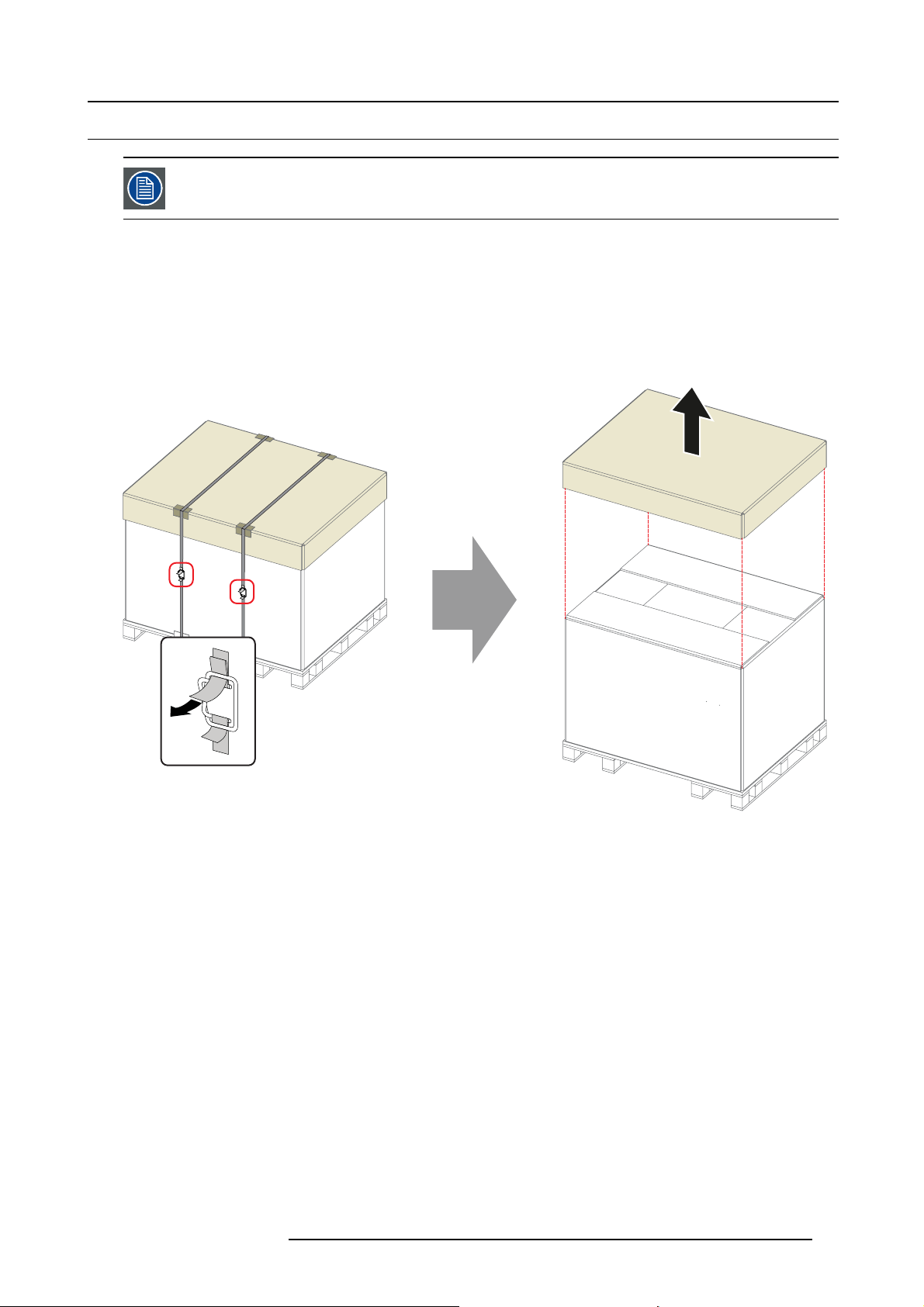
Image 2-3
3. Remove the inner cardboard box by sliding it up above t he projector.
Loosen the banding by pulling the free end o f the banding lo
op in the clip.
Remove the upper piece o f cardboard from the projector.
Image 2-4
4. L ift up the projector (with the supporting wooden board) from the pallet. A hoisting tool is recommended.
Make sure the 4 screws on the underside of the wooden board are accessible.
Release the projector from the supporting wooden board by removing the 4 screws.
Warning: It is forbidden to lift up the projector with manpower, use a hoisting tool instead. Do n ot underestimate the weight of
the projector. The projector weights ± 210 kg (±462 lb.).
12
R5905823 HDQ 4K35 30/11/2015
Page 17
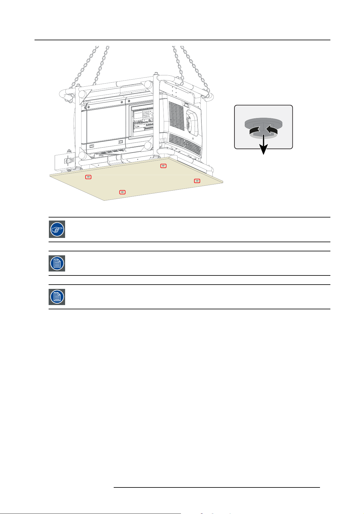
Image 2-5
2. General
4x
Save the original shipping carton and p acking material, they will be necessary if you ever have to ship your
projector. For maximum protection, repack you r projector as it was o riginally packed at the factory.
A rubber foam inside a plastic bag is placed into the lens opening of the projector. It’s recommended to reuse
this foam and plastic back each time yo u transport the projector. This to prevent intrusion of dust and foreign
particles.
The lens is delivered in a separate box.
R5905823 HDQ 4K35 30/11/2015 13
Page 18

2. General
2.3 Initial inspection
General
Before shipment, the projector was inspected and found to be free of mechanical and electrical defects. As soon as the projector is
unpacked, inspect for any damage that m ay have occurred in transit. Save all packing material until the inspection is completed. If
damage is found, file claim with carrier immediately. The Barco Sales and Service office should be notified as soon as possible.
The packaging of the HDQ 4K35 projector is provided with a shock-watch label. If this shock-watch label
was triggered (red colored at arrival) during transport, that indicates that the package w as possi
handled by the transport company. In this case, the instructions m entioned on the label, should be followed,
which are: adding a note on the “bill of lading” and informing the transport company and the Barco sales and
service office as s oon as possible.
bly roughly
Box content
After unpa cking the projector it is recommended to check if all following items where include
• Safety manual
• Quick start guide
• Warranty card
• CD-ROM with electronic version of the manuals
d:
Mechanical check
This chec k should confirm that there are no broken knobs or connectors, that the cabinet and panel surfaces are free of dents and
scratches, and that the operating panel is not scratched or cracked. The Barco Sales and Service office should be notified as soon
as possible if this is not the case.
14
R5905823 HDQ 4K35 30/11/2015
Page 19
2.4 Air inlets and outlets
Air inlets and outlets
2. General
Image 2-6
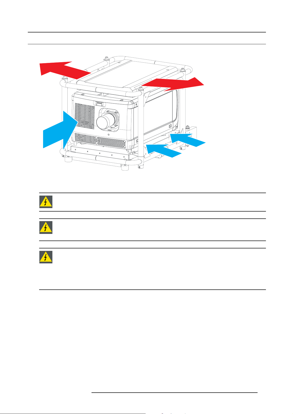
The HDQ 4K35 projector has 3 air inlets (1 at the front and 2
projector).
WARNING: When the projector is used in portrait mode, the air outlet is positioned towards the floor. That’s
why the floor covering can become ve ry hot and must be resistant to a temperature of 90 °C (194 °F).
WARNING: The air fi lters of the projector must be cleaned or replaced on a regular basis (a "clean" booth
would be monthly-minimum). Neglecting this could result in disrupting the air flow inside the projector, causing overheating. Overheating may lead to the projector shutting down during operation. See "Cleaning the
front dust filter", page 70 and "Cleaning the bottom dust filters", page 71.
WARNING: The projector is fan co oled and mu st be installed with sufficient space around the air inlets, mini-
mum 20 cm (8”) to ensure sufficient air fl
than 10 cm (4") on any side.
The pro jector must always be installed in a manner which ensures unimpeded evacuation of the hot air from
its cooling system.
The projector should be used in an area where the amb ien t tem perature, as measured at the projector air inlet,
does not exceed +35°C (+95°F).
ow. Loose papers or other objects may not be nearer to the projector
at the bottom) and 2 air outlets (on the exhaust box on top of the
R5905823 HDQ 4K35 30/11/2015 15
Page 20

2. General
2.5 Installation process overview
Let t he projector acclimatize after unpacking. Neglecting this may result in a startup failure of the Light Processor Unit.
Setup from A to Z
After you have unpacked and checked the projector you can start with the installation process of your Barco HDQ 4K35. T his chapter
gives y ou an overview of all the different stages in the installation process which you have to follow to set your HDQ 4K35 up and
running. Each stage is briefly described and r efers to more detailed step by step procedures in this manual. U se this overview as a
checklist to ensure that you have followed all stages in the setup process of your HDQ 4K35.
What has to be done?
1. C heck if all installation requirements are fulfilled such as the environment conditions of the installation area, electrical facili-
ties, etc. For m ore info see chapter "Installation requirements", page 10.
2. In stallation of the Lamp House. The Lamp House is delivered separately from your projector. Unpack the Lamp House and
install it in your projector. See chapter "Installation of the Lamp House", page 18.
3. In stallation of the Lens. Select and install an appropriate lens for your specific situation. Don’t forget to install the additional
lens fixation mechanism. S ee chapter "Installing the lens fixation mechanism", page 44.
4. Connect the pr ojector with the power net. Choose the correct power input configuration according to your local power net
and connect the projector. See chapters "Access to the power connection", page 19, and "Connecting the projector with the
power net", page 22. If necessary connect the projector electronics with a U PS. See c hapter "Connecting a UPS to the p rojector
electronics", page 23.
5. P o wer input set up and Electrical connection with the power net.Se
20 and "Connecting the projector with the power net", p age 22.
6. In stallation of the Comm un icator Touch Panel. See c hapter X XXX XX .
7. P hysical installation of the projector. Position your HDQ 4K35 in landscape or po rtrait mod e, see chapter "Landscape and
portrait m ode", page 25. If necessary, choose to stack multiple projectors, either in a standing (table mount) or hanging (ceiling
mount) configuration, see chapter "Stacking multiple projectors", page 27.
8. Switch ON the projector. See "Switching ON the HDQ", page 67.
9. C onnect your source to the appropriate input. Se e "Source input ports of the Barco HDQ 4K35 projector", page 60.
10.Select the input to w hich the source is connected. Use Communicator to make the selection.
11. Alignment of the projected image on the screen. The projector can now be switched on to project its first image (test pattern)
on the screen. Then the image can be aligned with the screen size of the application. Follow the nex t steps to ach ieve that:
a) Place the ON/OFF switch of the projector in the ”I” position. As a result the pr ojector starts to initialize. The status lights of
the projector lights up GREEN onc e the projector is initialized.
b) Press the STANDBY button on the local keypad to activate the lamp.
c) Press the DOWSER button on the local keypad to open th e dowser of the projector. T he dowser is open if the color of the
DOWSER button is GREEN.
d) Press the TEST PATTERN button on the local keypad to project one of the internal test patterns of the projector on the screen.
e) Use the lens ZOOM, SHIFT and FOCUS buttons on the local keypad the match the projected image with the screen. Tilt the
projector in ca se y ou can not SHIF T the image completely upon the screen.
12.Resetting the lamp p aram eters. The lamp parameters MUST be updated after each installation of an x enon lamp inside the
lamp house or when replac ing the complete lam p house.
time of the xenon lamp. Consult the Comm unicator software manual section Installation → Lamp.
13.Realignment of the xenon lamp in its reflector. For optimal performance of the xenon lamp it is required to realign the lamp
after installation in the lamp hous e. See "Realignment of the lamp in its refl ector", page 78 for more information.
14.Adjusting the light path
Nevertheless, some applications require a readjustment of the lens holder, convergence or both. See procedure "Sc heimpfl ug
adjustment", page 48.
15.(if applicable) A lign the projected images of the stacked projectors. See chapters "Adjusting the multifunctional frame", page
30 and "Aligning stacked pro jectors", page 34.
16.Projection of a source signal. Apply a single or dual channel DisplayPort (DP) source to the input ports of the projector and
start up the projector. See chapter "Source input ports o f the Barco HDQ 4K35 projector", page 60. Use the Communicator Touch
Panel to configure the applied source. S
. Normally the lens holder and the convergence of the projector is perfectly adjusted at the factory.
ee the user guide of the Communic ator Touch Panel for more detailed information.
Neglecting this update will result in poor performance and short life
e c hapter "Power input setup of the HDQ 4K35", page
16
R5905823 HDQ 4K35 30/11/2015
Page 21

3. PHYSICAL INSTALLATION
Overview
• Installation of the Lam p House
• Access to the power connection
• Power input setup of the HDQ 4K35
• Connecting the projector with the power net
• Connecting a UPS to the projector electronics
• Landscape and portrait mode
• Stacking multiple projectors
• Adjusting the multifunctional frame
• Aligning the projected image on the screen
• Aligning stacked projectors
3. Physical installation
R5905823 HDQ 4K35 30/11/2015
17
Page 22
3. Physical installation
3.1 Installation of the Lamp House
WARNING: Bef ore installing the Lamp House, d isconnect the power to the pro jector mains terminals and
unplug the power cord at the U PS INLET for removal of all power from the projector.
Necessary tools
10 mm nut driver or flat screwdriver
How to install the Lamp House in the projector?
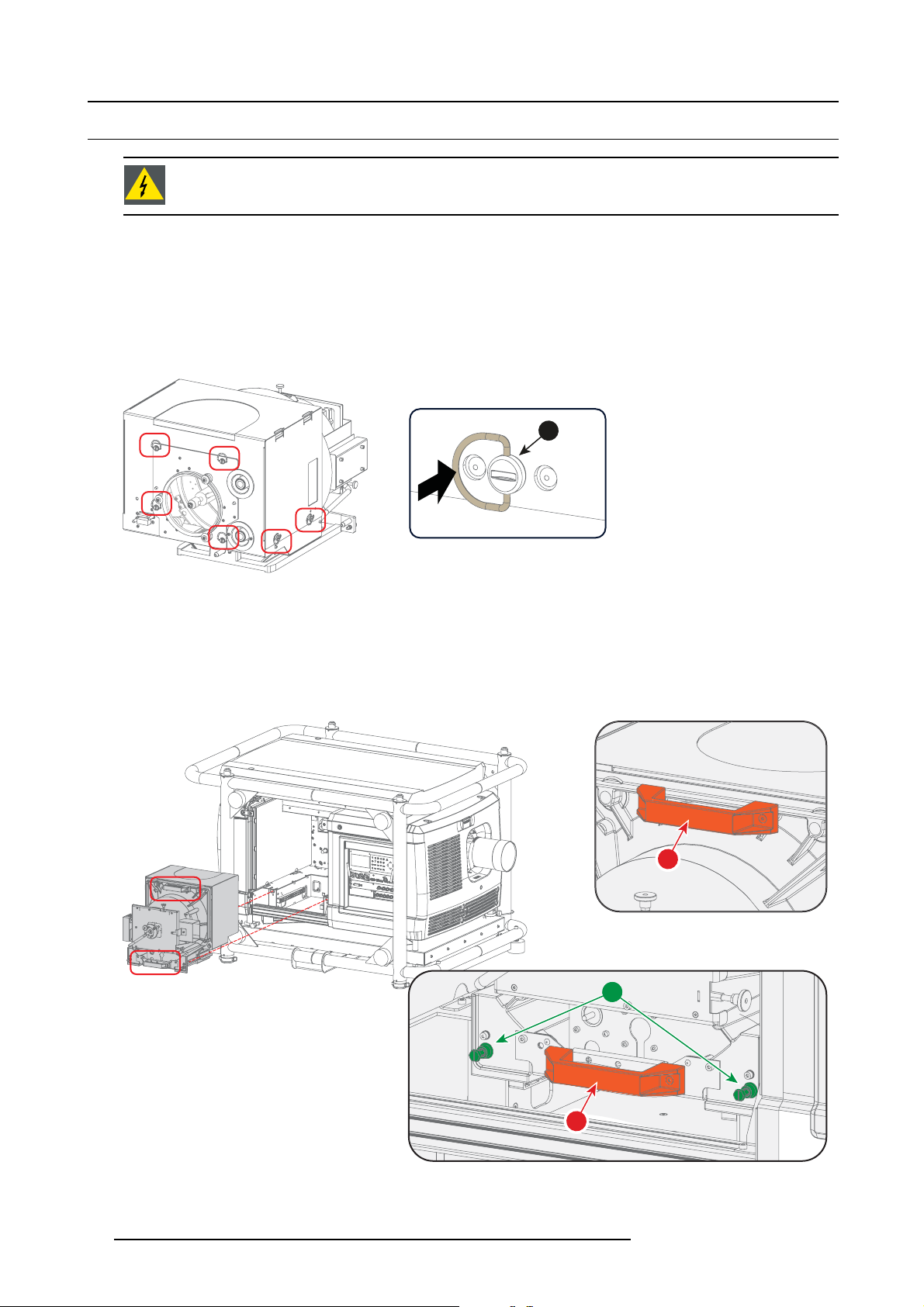
1. Remove the lamp cover.
2. P osition the turning wires of the six quarter turn screw s (1) so that they are fl ush w ith the cover. If this is not the case, interfer-
ence may occur while inserting the Lamp House.
1
Image 3-1
Positioning the quarter turn screws
3. G rip the Lamp House by both handles (2 and 3) and place the front of the Lamp House on the base plate inside the lamp com-
partment of the projector, lining up the foot of the Lam p H ouse w i
Warning: Be aware of the weight of the Lamp House. Take the necessary precautions to avoid personal injury.
4. P ush the Lamp House fully into the slots.
5. S ecure the Lamp House by fastening the two retaining screws (1) at the base of the Lamp House. Use a 10 mm nut driver or a
flat scre w d river.
th the s lots on the base.
3
1
Image 3-2
Installation of the Lamp House
6. Install the lamp cover.
18
2
R5905823 HDQ 4K35 30/11/2015
Page 23
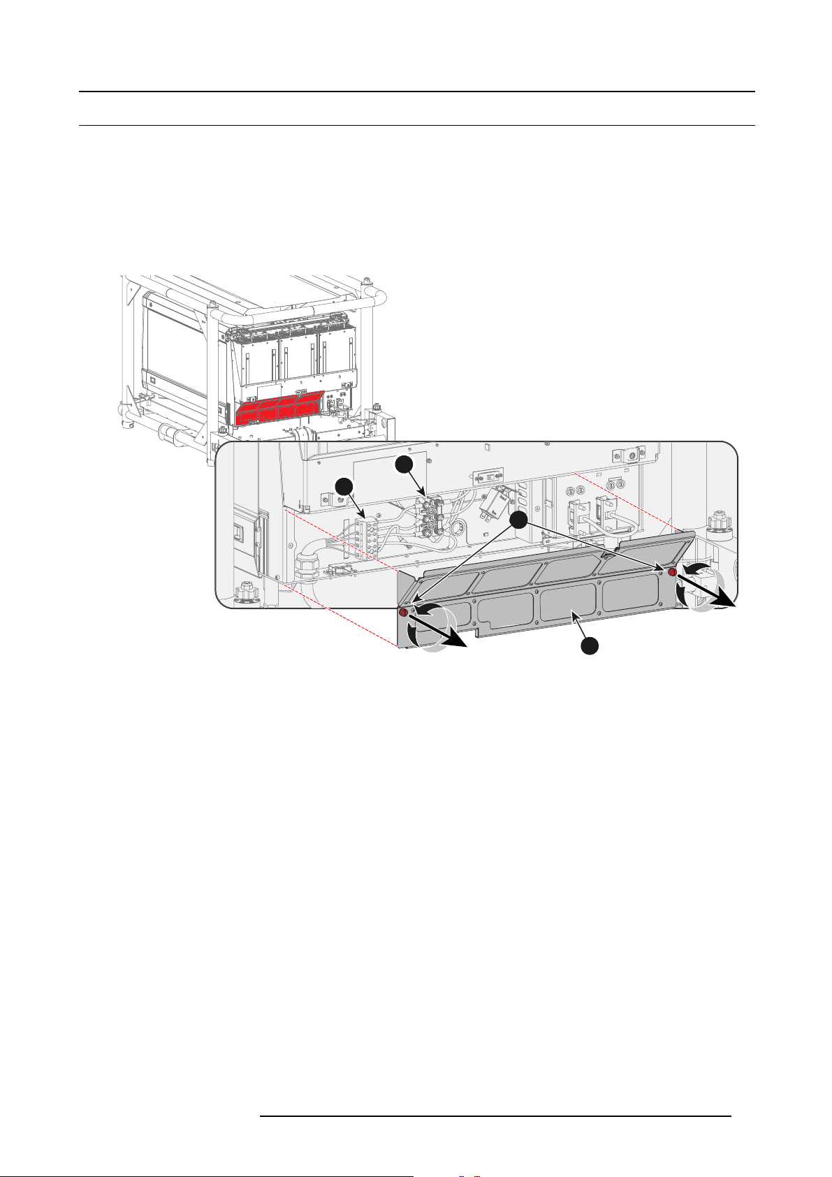
3.2 Access to the power connection
Necessary tools
Flat screwdriver - 6 mm
How to get access to the power connection of the projector?
1. R emov e the back cover of the projector. See "Removal of the back cover", page 88.
2. R elease the 2 captive screws (1).
3. R emov e the power connection cover (2).
4
3
3. Physical installation
Image 3-3
Power connection access
The terminal barrier strip (3) and Y-Δ configuration block (4) is accessible.
1
2
R5905823 HDQ 4K35 30/11/2015
19
Page 24
3. Physical installation
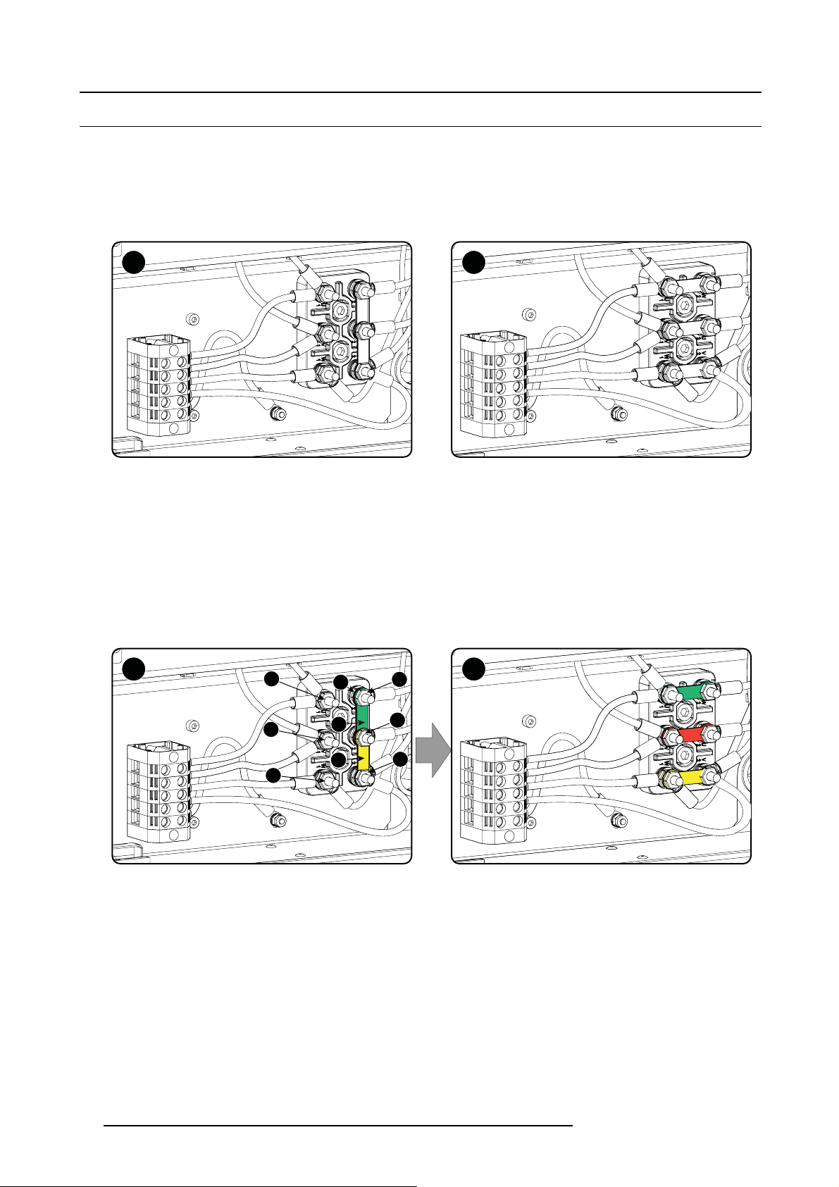
3.3 Power input setup of the HDQ 4K35
About the power input
The projector power input can be configured for a power supply of 230/400V 3W+N+PE (Υ-connection) or for 208V 3W+PE (Δ-connection). Before operating the projector, place the links in the correct position depending on the local power supply.
For a 3W+N+PE system, 400V is measured between the lines, 230V is measured between the lines and the neutral.
For a 3W+PE system, 208V is measured between the lines.
A B
Image 3-4
Υ-Δ connection
A Υ connection
B Δ connection
Necessary tools
• Flat screw driver
• Wrench10mm
• Torque wrench 10 mm
HowtoswitchfromaΥ-connection to Δ-connection
1. L oosen the 6 top nuts on the Υ/Δ configuration block. (1 to 6)
Y Δ
Image 3-5
Υ to Δ connection
2. Take off the mounted lins (A, B and C). Two links above each other or mounted between the upper and middle pin (A, B) and one
link between the middle pin and lower pin (C).
3. M ount the links horizontally on the pins.
4. Turn a nut on each pin and secure wit
1
2
3
A
B
C
h a torque wrench set to 7.5 Nm.
4
5
6
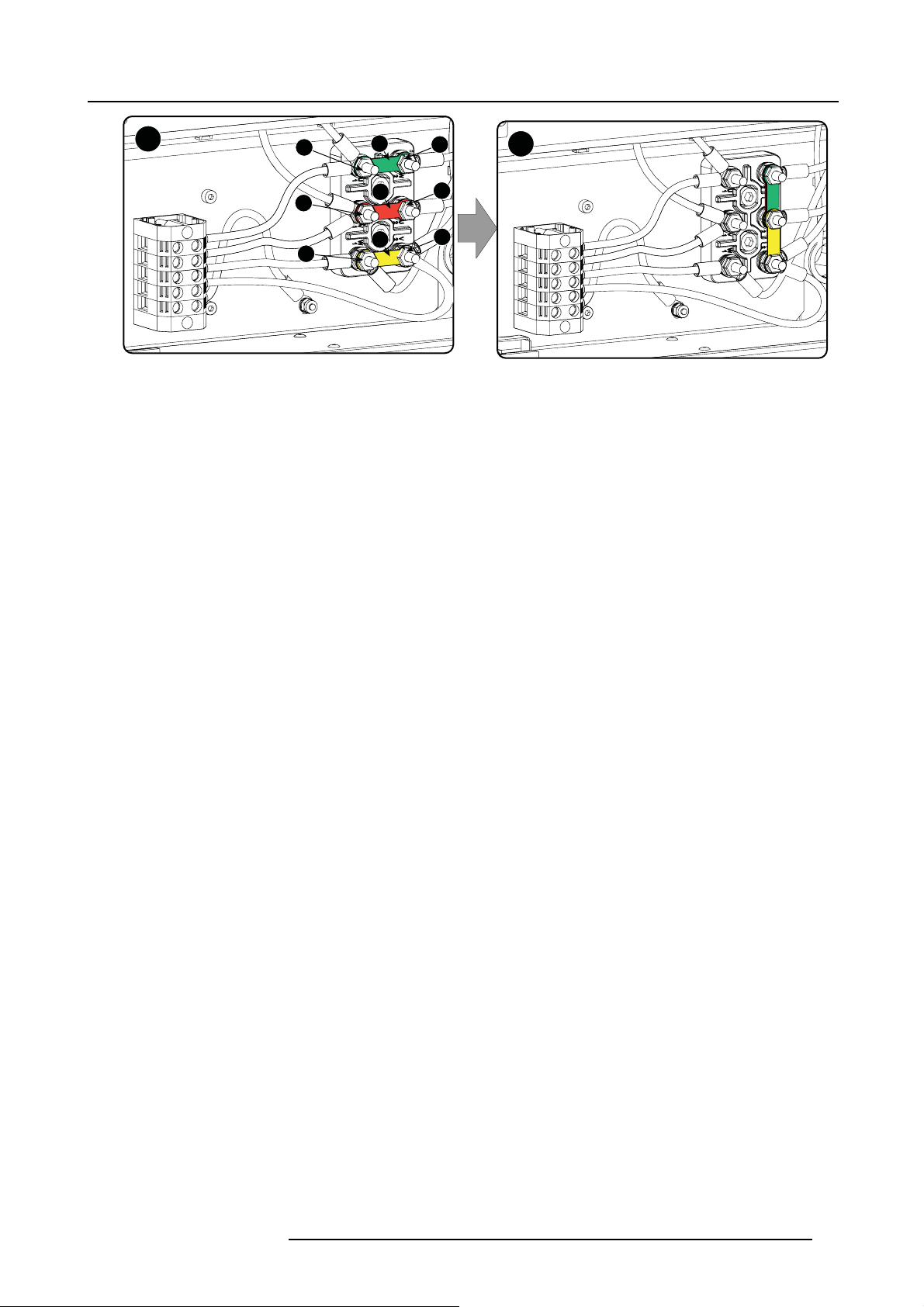
HowtoswitchfromaΔ-connection
1. L oosen the top nuts on the Υ/Δ configuration block (1 to 6).
20
to Υ-connection
R5905823 HDQ 4K35 30/11/2015
Page 25
3. Physical installation
Δ
Image 3-6
Δ to Υ connection
2. Take off the mounted links (A, B and C).
3. Connect the right pins together. Place 2 links between the upper pin and the m iddle pin (A, B)and 1 link between the m iddle pin
and the lower pin (C).
1
2
3
A
B
C
4
5
6
Y
R5905823 HDQ 4K35 30/11/2015
21
Page 26
3. Physical installation
3.4 Connecting the projector with the power n et
WARNING: T he total electrical installation should be protected by an appropriate rated and readily accessi-
ble disconnect switch, circuit breakers and ground fault current interrupters. The installation shall be done
according to the local electrical installation codes.
WARNING: Make sure that the vo ltage range of projector mat ches with the voltage of the local power net.
CAUTION: The cross-sectional area of the conductors in the Power Supply Cord shall not be less than 4 mm
or AWG 10.
Necessary tools
• Flat torque screwdriver - 4 mm
• Adjustable wrench
Necessary parts
• (for 3W+N+PE, 230/400V) Certified power cable, minimum 4 mm² or AWG 10, 500V rated, cable diameter between 11 mm and
21 mm, or
• (for 3W+PE, 208V) Certified power cable, minimum 4 mm² or AWG 10, 300V rated, cable diameter between 11 mm and 21 mm
• Circuit breaker - maximum 40A
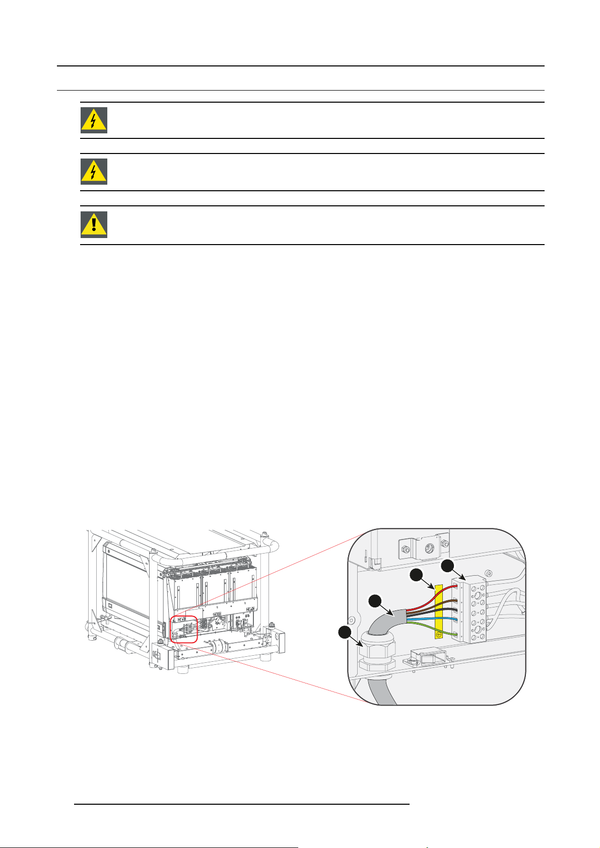
How to c onnect the projector with the power net?
1. R emov e the back cover of the projector. See "Removal of the back cover", page 88.
2. R emov e the power connection cover. See "Access to the power connection", page 19.
3. L oosen the cable gland fixation ring (1).
Note: The cable gland is specified for cables with a diameter between 11 mm and 21 mm .
4. P ush the stripped power supply cable (2) through the cable gland. When using a flexible power cord, make s ure each con ductor
end is provided with an end sleeve.
5. S ecure the cable in the cable gland by tightening the fixation ring with an adjustable w rench.
6. Connect each wire of the power cable with the term inal ba rrier strip (3), according to the legend on the decal (4). Tighten the
screws to a torque of 1.4 Nm.
Warning: Always connect ground conductor (PE) first.
Note: Always connect the neutral conductor (N) when available.
2
Image 3-7
Power connection
7. Install the power connection cov er.
8. Install the back cover of the projector. See "Removal of the back cover", page 88.
22
4
3
2
L2 NL3
L1
1
R5905823 HDQ 4K35 30/11/2015
Page 27
3. Physical installation
3.5 Connecting a UPS to the projector electronics
UPS
Uninterruptible Power Supply
Introduction
This proce dure explains how the projector electronics can be connected with a UPS. By default, the projector is configured for use
without a UPS. A short power link cable (with plug type C13/C14) loops the power through to the projector elec
WARNING: Only use UPS units which are suitable for the HDQ 4K35.
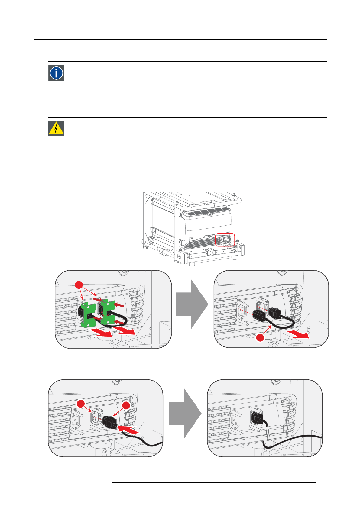
How to connect a UPS to the projector electronics?
1. Install the UPS according to the instructions of the manufacturer and the local regulations.
2. Remove the short power link cable if present:
a) Remove both fixation springs (1) by squeezing them together and pulling them away from the power plugs.
b) Unplug both power plugs from the short power link cable (2).
tronics.
1
1
Image 3-8
3. Connect the power output cord from the UPS unit (1) to the UPS inlet socket of the projector (right socket) (2).
Tip: Position the cable behind the back cover instead of directly connecting the power p lug. This will make it possible to
remove the back cover without unplugging the UPS inlet cable.
2
Image 3-9
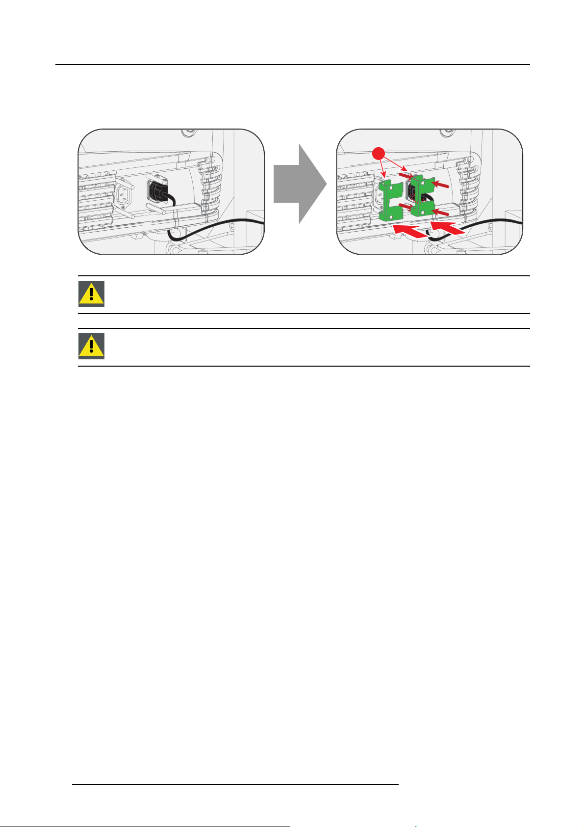
4. S e cure the UPS inlet soc ket with a fixation spring:
1
1
2
R5905823 HDQ 4K35 30/11/2015
23
Page 28
3. Physical installation
a) Squeeze the fixation spring together (1).
b) While squeezing, slide the fixation spring on the pins and push it against the power plug.
c) Release the fixation spring.
Tip: Install the second fixation spring on the power outlet socket to prevent losing it.
Image 3-10
CAUTION: The electrical connection with the UPS INLET socket of the projector must be done with a certified
AC power supply cord (minimum 0,75 mm² or 18 AWG and minimum 300V)
CAUTION: Do not use the power OUTLET socket of the projector to provide power to other equipment!
1
1
24 R5905823 HDQ 4K35 30/11/2015
Page 29
3.6 Landscape and portrait mode
In the allowed positions, an additional inclination or rotation of ±15° is tolerated.
The inclination and rotation of the projector in the frame is included in these ±15°.
Example: the p rojector is positioned in lan dscape mode and is rotated in the frame for 3°. An additional frame
rotation of 12° of is allowed.
Landscape and portrait mode
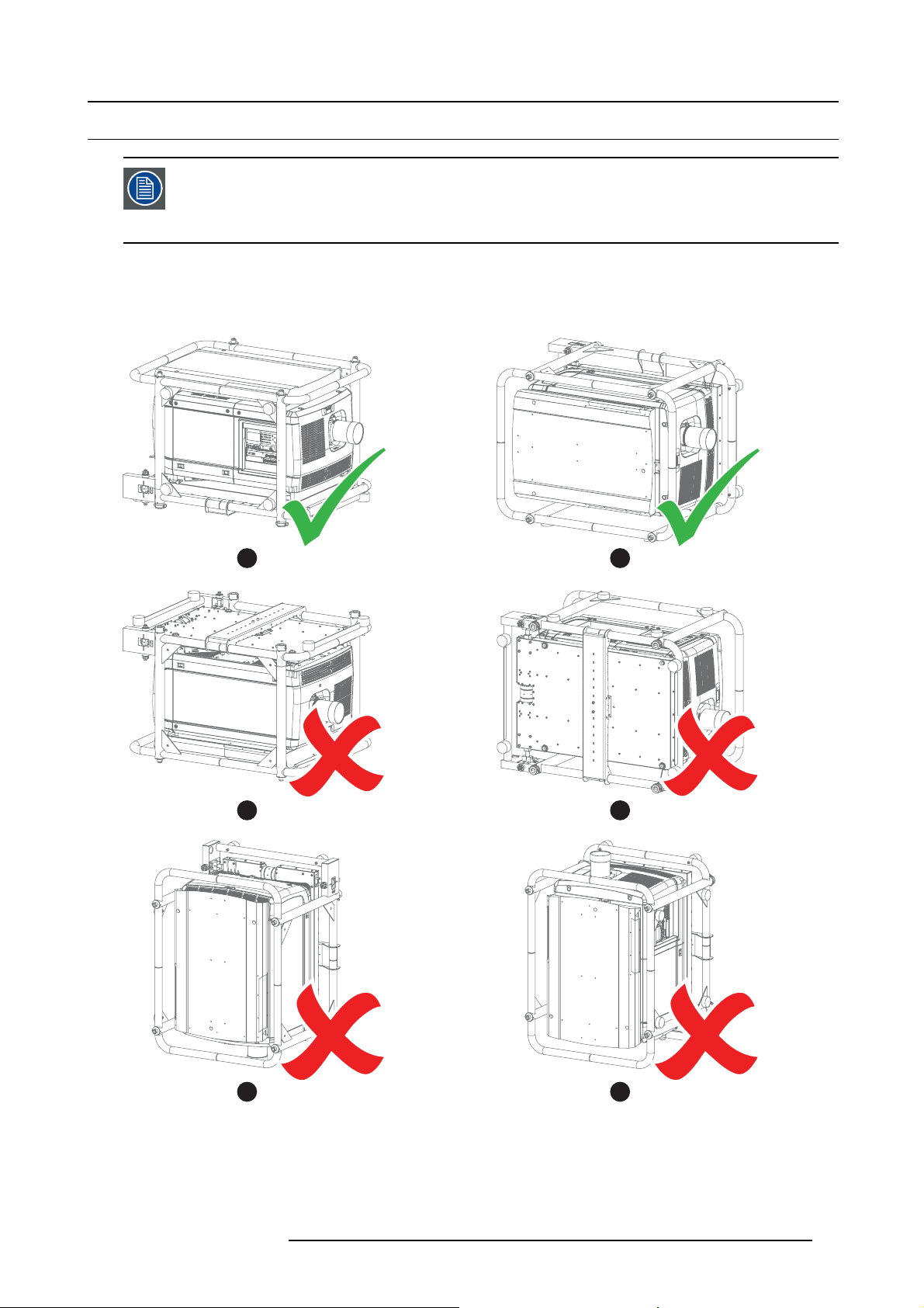
The projector can be used in landscape or portrait mode.
The illustrations below shows which positions are allowed and which are not.
3. Physical installation
A B
C D
E F
Image 3-11
A Landscape mode (allowed)
B Por trait mode (allowe d)
C Upside down (disallowed)
D Turned over portrait mode (disallowed)
E Upwards (disallowed)
F Downwards (disallowed)
R5905823 HDQ 4K35 30/11/2015 25
Page 30

3. Physical installation
CAUTION: Do not use the projector in a d isallowed position. Failure to do so can cause irreversible damage
to the projector.
WARNING: It is not allowed to stack multiple projectors in portrait mode.
CAUTION: When the pro jector is used in portrait m ode, always ensure the cooling liquid level is sufficient.
To check the cooling liquid level, see "Checking cooling liquid level", page 74.
26 R5905823 HDQ 4K35 30/11/2015
Page 31

3. Physical installation
3.7 Stacking mult iple projectors
Introduction
The Barco HDQ 4K35 is mounted by default in a multifunctional frame. This frame can be used to stack multiple projectors onto
each other. The stacked projectors can be used in a standing (table mount) or hanging configuration (ceiling mount).
WARNING: Never stack more than three (3) projectors in a standing configuration (table mount) and never
stack more than two (2) pro jectors in a hanging co nfiguration (ceiling mount). Failure to do so can cause
serious injury or death.
WARNING: It is not allowed to stack multiple projectors in portrait mode.
WARNING: It is forbidden to lift up the projector with manpower, use a hoisting tool instead. Do not under-
estimate the w eight of the projector. The projector weights ±210 kg (±462 lb.).
WARNING: When the projector is suspended from a truss, m inimum four (4) clamps must be used to secure
the projector. The clamp s must be fixed to the projector frame. Use a truss which is capable of handling five
(5) times the complete load of the system.
WARNING: W hen the projector is suspended from a truss, always mount 2 safety cables around the projector
frame and the truss.
When a dual stacking configuration is suspended from a truss, always m oun t 2 extra safety cables around
both projector frames. See the procedure below for the correct use of these cables.
Allowed configurations
The illustrations below show which configurations are allowed. All other stacking configurations are not allowed.
Image 3-12
Allowed con figurations - table mount
R5905823 HDQ 4K35 30/11/2015 27
Page 32

3. Physical installation
Image 3-13
Allowed con figurations - ceiling mount
How to stack multiple projectors?
1. P osition the first projector on a solid and level surface.
2. Remove the 4 pipe lynch pins (1) from the frame of the second projector.
3. L ift up the second projector and position it on the fi rst projector (2). Make sure the pins of the lo wer frame fit in the holes of the
upper frame.
Warning: It is forbidden to lift up the projector with manpower, use a hoisting tool instead. Do n ot underestimate the weight of
4. S lide in the 4 pipe lynch pins (3) and secure them by swinging the lever (4).
1
the projector. The projector weights ± 210 kg (±462 lb.).
1
1 1
2
3
Image 3-14
Stacking projectors
5. M ount 2 (two) safety cables to secure both projector frames to each other:
28
4
R5905823 HDQ 4K35 30/11/2015
Page 33

3. Physical installation
2x
a) Push the safety hook through the loop of the safety cable and wrap the bottom frame.
b) Mount the other end of the safety cable around the upper frame and clasp the safety hook around the cable as illustrated.
Make sure that the falling distance is max imum 20 cm (8”). If necessary, before clasping the safety hook around the cable,
turn the cable a few time around the fram e.
c) Repeat this procedure for the other safety cable on the other side of the frame.
2x
Image 3-15
R5905823 HDQ 4K35 30/11/2015 29
Page 34

3. Physical installation
3.8 Adjusting the multifunctional frame
Introduction
The Barco HDQ 4K35 is mounted by default in a multifunctional frame. This frame can be used to adjust the projector po sition. The
frame can be adjusted in 3 different ways:
• inclinating
• rotating
•skewing
The image below ex plains these 3 terms.
Image 3-16
A Inclinating
B Rotating
CSkewing
A
B
C
Necessary tools
• 2.5 mm Allen wrench
• 17 mm wrench
How to inclinate and rotate the projector in the frame?
1. Release the locking screw(s) (1) on the adjustment mechanism(s) on the back of the fram e. Use a 2.5 mm Allen wrench.
2. Turn the left and right adjustment screw (2) anti clockwise to lower the back of the projector
Or,
clockwise to rise the back of the projector.
Note: A 17 mm wrench can be used to turn the adjustment sc rews.
3. Turn the left and right adjustment screw (2) in the opp osite direction to rotate the projector.
4. Tighten the locking screw(s) (1). Use a 2.5 mm Allen wrench.
30
R5905823 HDQ 4K35 30/11/2015
Page 35

3. Physical installation
1
2
2
1
Image 3-17
Inclinating and ro tating the projector
How to skew the projector i n the frame?
1. Release the locking screw(s) (1) on the adjustment mechanism on the bac k of the frame. Use a 2.5 mm Allen wrench.
Tip: Only the most reachable locking screw(s) on the adjustment rod may have been secured previously.
2. Turn the adjustme nt rod (2) clockwise to skew the projector clockwise
Or,
anti clockwise to skew the projector anti clockwise.
3. Tighten the locking screw(s) (1). Use a 2.5 mm Allen wrench.
Tip: Only secure the most reachable locking screw(s).
2
1
Image 3-18
Skewing the projector
R5905823 HDQ 4K35 30/11/2015 31
Page 36

3. Physical installation
3.9 Aligning the projected image on the screen
About aligning
Use the Communicator software to align the projector. For more detailed information, consult the Communicator software user guide.
Alignment steps
1. P roject an internal hatch pattern w ith the projector. In the navigation pane, click on Control → Test Patterns.
Use one of the short cuts to display a test pattern.
2. A djust the rotation of the projector.
Adjust until the outline of the hatch pattern is most symm etric with the projection screen.
Rotation
Image 3-19
3. A djust the inclination of the projector.
Adjust until the outline of the hatch pattern is most symm etric with the projection screen.
Inclination
Image 3-20
4. A djust the skew of the projector.
Adjust until the outline of the hatch pattern is most symm etric with the projection screen.
Skew
Image 3-21
5. S hift the hatch pattern horizontally and vertically until the outline of the hatch pattern is most symmetrically placed with respect
to projection screen.
Use Communicator software to shift. In the navigation pane, click on Configuration → Lens.TheLens settings menu opens.
Use the Lens shift buttons to shift the image.
Or, use the shift buttons on the local keypad.
32
R5905823 HDQ 4K35 30/11/2015
Page 37

3. Physical installation
Shift
Image 3-22
6. Z oom the hatch pattern in or out until the outline of the hatch pattern matches exactly the outline of the projection screen.
Use Communicator software to zoom . In the navigation pane, click on Configuration → Lens.TheLens settings menu opens.
Use the Lens zoom buttons to zoom the image.
Or, use the zoom buttons on the local keypad.
Zoom
Image 3-23
7. Repeat from step 2 until the hatch pattern of the stacked projec tor is perfectly aligned with the projection screen.
8. F ocu s the projector to the screen until the hatch pa ttern is perfectly sharp.
Use Communicator software to focus. In the navigation pane, click on Configuration → Lens.TheLens settings menu opens.
Use the Lens focus buttons to focus the image.
R5905823 HDQ 4K35 30/11/2015
33
Page 38

3. Physical installation
3.10 Aligning stacked projectors
Prior to starting the procedure below, make yourself familiar with the adjustment mechanism of the multifunctional frame. See " Adjusting th e multifunction a l frame", pag e 30.
Reference projector
In c ase of a s tanding configur ation (table mount), this is the lowest projector.
In c ase of a hanging configur ation (ceiling mount), this is the uppermost projector.
Necessary tools
• 2.5 mm Allen wrench
• 17 mm wrench
How to align stacked projectors
1. A lign the reference projector on the screen. See "Aligning the projected im age on the screen", page 32.
2. P roject an internal hatch pattern with the reference projector. In the na vigation pane, click on Control → Te s t Pa t t e r n s and
select a hatch pa ttern .
Note: The pattern must be s harp and must have a perfect rectangle outline.
If this is not the case, readjust the reference projector before aligning the other stacked projector(s) with the reference
hatch pattern.
3. P roject the same internal hatch pattern with the stacked projector. I n the navigation pane, click on Control → Test Patterns and
select a hatch pa ttern .
4. A djust the rotation of the stacked projector with respect to the reference projector.
Adjust until the outline of the hatch pattern is most symmetric with the reference ha
tch pattern.
Rotation
Image 3-24
5. A djust the inclination of the stacked projector with respect to the reference projector.
Adjust until the outline of the hatch pattern is most symmetric with the reference hatch pattern.
Inclination
Image 3-25
6. Adjust the skew of the stacked projector with respect to the reference projector.
Adjust until the outline of the hatch pattern is most symmetric with the reference hatch pattern.
34
R5905823 HDQ 4K35 30/11/2015
Page 39

3. Physical installation
Skew
Image 3-26
7. S hift the hatch pattern horizontally and vertically until the outline of the hatch pattern is most symmetrically placed with respect
to the reference hatch pattern.
Use Communicator software to shift. In the navigation pane, click on Configuration → Lens.TheLens settings menu opens.
Use the Lens shift buttons to shift the image.
Or, use the shift buttons on the local keypad.
Shift
Image 3-27
8. Z oom the hatch pattern in or out until the outline of the hatch pattern matches exactly the outline of the reference hatch pattern.
Use Communicator software to zoom . In the navigation pane, click on Configuration → Lens.TheLens s ettings m enu opens.
Use the Lens zoom buttons to zoom the image.
Or, use the zoom buttons on the local keypad.
Zoom
Image 3-28
R5905823 HDQ 4K35 30/11/2015 35
Page 40

3. Physical installation
9. Repeat from step 2 until the h atch pattern of the stacked projector is perfectly aligned with the hatch pattern of the reference
projector.
10.Focus the projector to the screen until the hatch pattern is perfectly sharp.
Use Communicator software to focus. In the navigation pane, click on Configuration → Lens.TheLens settings menu opens.
Use the Lens focus buttons to focus the image.
In case of a triple stacked standing projector configuration (table mount) adjust and align the reference projector fi rst, than the middle projector and finally the uppermost projector.
36 R5905823 HDQ 4K35 30/11/2015
Page 41

4. Lenses & Lens Holder
4. LENSES & LENS HOLDER
About this chapter
This chapter gives an overview of available lenses for the Barco HDQ 4K35 and explains how you can select the best suited lens for
your specific situation using the lens formulas. Also, it is explained how to install and remove a lens from the projector lens holder.
Furthermore, it is described how you can perform the Scheimpflug adjustment.
CAUTION: Never transport the projector with a lens mounted in the Lens Holder. A lways remove the le
before transporting the projector. Neglecting this can d amag e the Lens Holder and Prism.
Overview
• Available lenses
• Lens selection
• Lens installation
• Lens removal
• Installing the lens fixation mechanism
• Removing the lens fixation mechanism
• Lens shift, zoom & focus
• Additional vertical shift of the Lens Holder
• Scheimpflug adjustmen t
• Fixation of the Lens Holder front plate
ns
R5905823 HDQ 4K35 30/11/2015
37
Page 42

4. Lenses & Lens Holder
4.1 Available lenses
Which lenses are available for my projector?
The table below is subject to changes. Consult Barco’s w eb site and click on myBarco for the most recent
information about available lenses.
Product Number Zoom range Image
R9852950 1,0 ( fixed) image 4-1
R9852090 1,45 – 1,8 image 4-2
R9852092 1,8–2,4 image4-3
R9852094 2,2–3 image4-4
R9852100 2,8–5,5 image4-5
R9852920 5,5–8,5 image4-6
R9856294 1,35 – 1,86 image 4-7
R9856297 1,46 – 2,10 image 4-8
R9856300 1,65 – 2,60 image 4-9
Image 4-1
R9852950
Image 4-4
R9852094
Image 4-2
R9852090
Image 4-5
R9852100
Image 4-3
R9852092
Image 4-6
R9852920
38 R5905823 HDQ 4K35 30/11/2015
Page 43

4. Lenses & Lens Holder
Image 4-7
R9856294
Image 4-8
R9856297
Image 4-9
R9856300
R5905823 HDQ 4K35 30/11/2015 39
Page 44
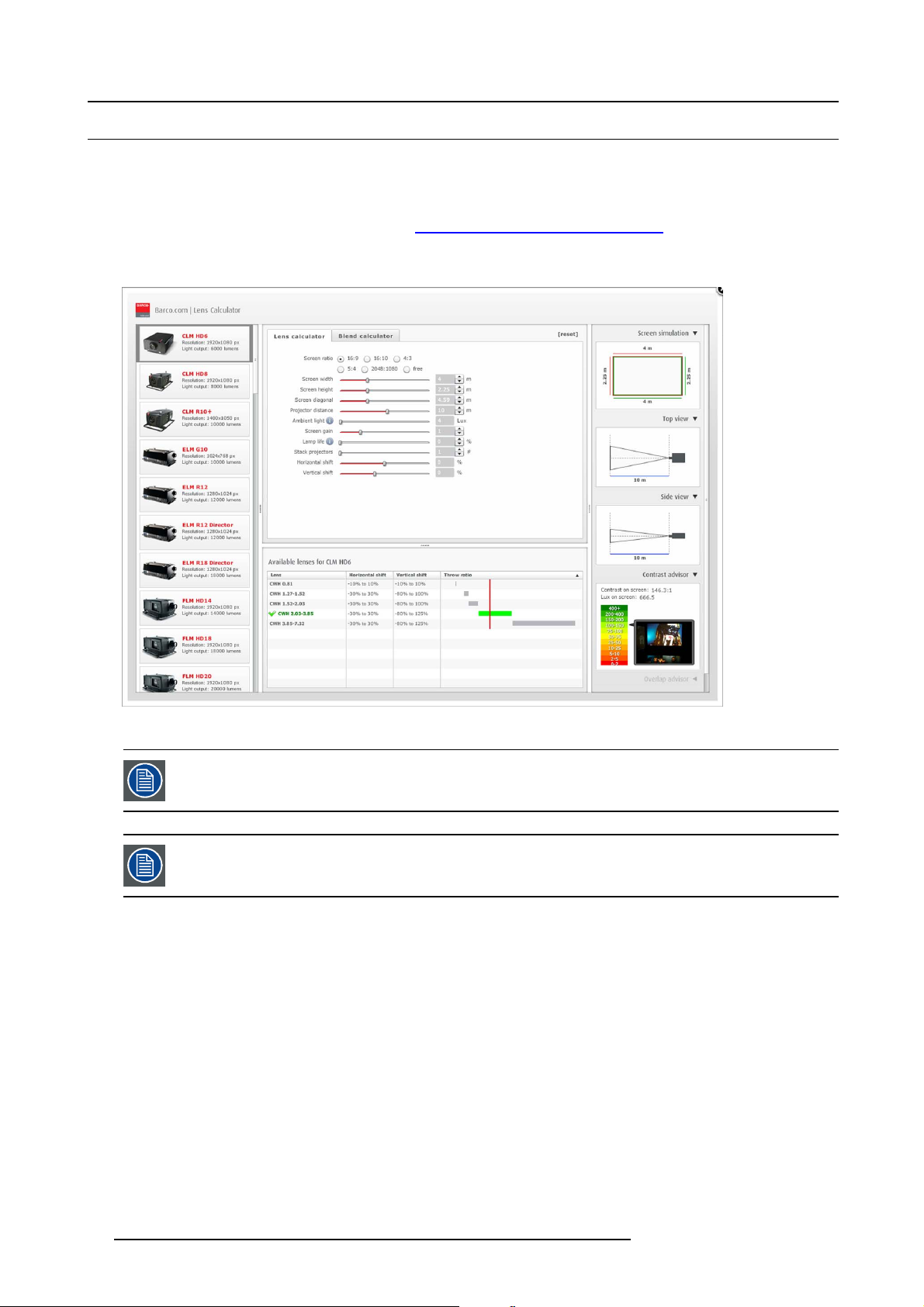
4. Lenses & Lens Holder
4.2 Lens selection
How to select the right lens
1. Determine the required sc reen width (SW).
2. Determine the approximate position of the projector in the room.
3. S tart up the Lens Calculator on the Barco website: h
for your config uration.
The Lens Calculator window opens.
ttp://www.barco.com/en/tool s/lenscalculator to determine the possible lenses
Image 4-10
Lens calculator
The Lens Calculator can also be used to determine the position of the projector when the lens type and screen
width is known.
Due to lens tolerances the results of calculated values may be d ifferent from measured values. These difference may vary +/- 5%.
40 R5905823 HDQ 4K35 30/11/2015
Page 45

4.3 Lens installation
WARNING: Ensure saf e fixation of the projector lens. The lens fixation mechanism m ust be installed. S ee
"Installing the lens fixation mechanism", page 44
How to install a lens?
1. Remove the plastic lens holder cover.
a) Put the lock (1) into the unlock position.
b) Take out the plastic cover.
4. Lenses & Lens Holder
12
Image 4-11
2. Take the lens assembly out of its packing material and remove the lens caps on both sides.
3. P lace the lens holder in the “unlocked” position by moving the lens lock handle (1) towards the lens power supply socket (2).
3
2
1
1 2
Image 4-12
Unlock lens holder
R5905823 HDQ 4K35 30/11/2015 41
Page 46

4. Lenses & Lens Holder
4. E nsur e that the lens holder stands in the On-Axis position (horizontal and vertical mid position).
Note: The lens holder is placed default in the On-Axis position at factory.
5. G ently insert the lens in such a way that the lens connector matches the socket.
Image 4-13
Mount lens
6. Insert the lens until the connector seats into the s ocket.
- the pin (3) o n the lens holder matches with the sleeve in the lens.
- the connec tor se ats into the socket (2)
Warning: Do not r elease the Lens yet, as the L ens may fall out of the Lens Holder.
7. S ecur e the lens in the lens holder by sliding the lens lock handle into the “locked” position, which is away from the lens power
supply socket. Ensure the lens touches the front plate of the lens holder.
Image 4-14
Fix lens
8. Continue with the installation o
f the lens fixation mechanism, see "Installing the lens fixation mechanism", page 44.
CAUTION: Never transport the projector with a Lens mounted in the Lens Holder. Always remove the Lens
before transporting the projector. Neglecting this can d amag e the Lens Holder and Prism.
42 R5905823 HDQ 4K35 30/11/2015
Page 47

4. Lenses & Lens Holder
4.4 Lens removal
How to remove a lens?
1. S upport the lens with one hand while you unlock the lens holder by sliding the lock handle tow ards the “unlocked” position as
illustrated.
Image 4-15
Unlock lens
2. G ently pull the lens out of the lens holder.
Image 4-16
Remove lens
It’s recommended to place the Lens caps of the original Lens packag ing, back on both sides of the removed
Lens to protect the optics of the Lens.
It’s recommended to place the foam rubber of the original pro jector packaging, back into the Lens op ening to
prevent intrusion of dust. N ote that this foam rubber is packed in a plastic bag to prevent the dust, emitted by
the foam , from e ntering the projecto r.
R5905823 HDQ 4K35 30/11/2015 43
Page 48

4. Lenses & Lens Holder
4.5 Installing the lens fixation mechanism
WARNING: Ensure saf e fixation of the projector lens. The lens fixation mechanism m ust be installed. S ee
"Installing the lens fixation mechanism", page 44
Necessary tools
10 mm wrench
How to install the lens fixation mechanism?
1. P lace the 2 lens fixa tion brackets (1) into position, as illustrated below. The fixation brackets must prevent the lens from com ing
loose from the Lens Holder.
2. S ecure the fix ation brackets by installing a nut (2) on each bracket. Use a 10 mm w rench.
1
2
Image 4-17
Installing the lens fixation mechanism
Depending on which lens is used, it may not always be possible to install the fixation brackets at the positions
showed on the illustration. In that case, the brackets may be installed on the underside o f the lens, following
the same principle. Always install 2 fixation brackets.
1
1
1
44 R5905823 HDQ 4K35 30/11/2015
Page 49

4.6 Removing the lens fixation mechanism
Necessary tools
10 mm wrench
How to remove the lens fixation mechanism?
1. R emov e the nuts (2) from the fixation brackets. U se a 10 mm wrench.
2. R emov e the fixation brackets (1) from the Lens Holder.
4. Lenses & Lens Holder
1
1
Image 4-18
Removing the lens fixation mechanism
2
R5905823 HDQ 4K35 30/11/2015 45
Page 50

4. Lenses & Lens Holder
4.7 Lens shift, zoom & focus
Motorized lens adjustment
The HDQ is equipped with a motorized lens shift functionality and a motorized zoom & focus functionality. A djustments can be done
with the keys on the local keypad or via Communicator software.
How to shift the lens
1. U se the up and down arrow keys on the local keypad to shift the lens vertically and use the left and right ar row keys on t he
local keypad to shift the lens horizontally.
Image 4-19
Or,
in Communicator, c lick in the nav igation pane on Configuration → Lens
How to zoom in or out
1. Is the zoom lens equipped with a motorized zoom?
If yes, use the “+” and “-” zoom keys on the local keypad to zoom in or out.
Image 4-20
If no, use the zoom barrel on the lens to zoom in or out.
How to focus
1. U se the “+” and “-” focus keys on the local keypad to focus the image on the screen.
Image 4-21
Take into account that the lens focus may slightly drift while the lens is warming up from cold to operation
temperature. This is a typical phenomen on for projection lenses used with high brightness projectors. The
operation tempe rature of the lens is reached after approximately 30 minutes projection of average video.
46 R5905823 HDQ 4K35 30/11/2015
Page 51

4. Lenses & Lens Holder
4.8 Additional vertical shift of the Lens Holder
Introduction
The lens of the HDQ 4K35 can be shifted vertically. The maximum vertical shift range is ±110% in both directions, which is not
sufficient in some situations. To extend the vertical s hift range in a certain direction, the L ens Holder can be shifted m anually.
Extending the vertical shift rang e in a certain direction, will reduce the available range in the other direction.
Necessary tools
3 mm Allen wrench
How to shift the Lens Holder?
1. R emov e the front projector cover. See "Removal of the front cover", page 86.
2. Loosenthe4screws(1)untilthecentralpartoftheLensHolderbecomesloose. Usea3mmAllenwrench.
3. S hift the central part up or down as desired. The lowermost, m iddle and uppermost shift positions are marked on the Lens Holder
with a little arrow (2).
4. Tighten the 4 screws (1) to a torque of 8.4 Nm.
2
Image 4-22
5. Install the front projector cover. See "Installation of the front cover", page 87..
1
2
R5905823 HDQ 4K35 30/11/2015
47
Page 52

4. Lenses & Lens Holder
4.9 Scheimpflug adjustment
What has to be done ?
The lens holder has to be adjusted so that the “sharp focus plane” of the projected image falls together with the plane o f the screen
(Fp1→Fp2). This is achieved by changing the distance between the DMD plane and the lens plane (Lp1→Lp2). The closer the lens
plane comes to the DMD plane the further the sharp focus plane will be. It can sometimes happen that you won’t be able to get a
complete focused ima ge on the screen due to a tilt (or swing) of the lens plane w ith respect to the DMD plane. This is also known
as Sheimpflug’s law. To solve this the lens plane must be placed parallel with the DM D plane. This can be achieved by turning the
lens holder to rem ove the tilt (or swing) between lens plane and DMD plane (Lp3→Lp4).
Lp1
Lp2
DMD
Image 4-23
Scheimpflug principle
Scheimpflug principle
The "plane of sharp focus" can be changed so that any plane can be brought into sharp focus. When the D M D plane
and lens plane are parallel, the plane of sharp focus will also be parallel to these two planes. If, h owever, the lens
plane is tilted with respect to the DMD plane, the plane of sharp focus will also be tilted according to geometrical and
optical properties. T he DMD plane, the principal lens plane and the sharp focus plane will intersect in a line be low the
projector for downward lens tilt.
Scheimpflug adjustment points
A
a
B
1
Fp1
SCREEN
Fp2
DMD
Lp3
Lp4
(Scheimpflug)
Fp4
Fp3
SCREEN
b
2
Image 4-24
Scheimpflug adjustments
4
C
d
D
3
c
Indication on drawing Function
4 Locking nut
1, 2 and 3
Scheimpflug adjustment nuts
A, B, C and D Set screws
a, b, c and d lock nuts
1, 2 and 3 are adjustment points.
4 is a locking point and NOT us ed during Scheimpflug adjustment.
48
R5905823 HDQ 4K35 30/11/2015
Page 53

4. Lenses & Lens Holder
Necessary tools
• Allenkey3mm
• Nut driver 13 mm
• Nut driver 10 mm
How to adjust
1. P roject a green focus pattern. For a 4K projector, use the 4K test pattern. Otherwise, use the 2K test pattern.
Image 4-25
2. L oosen the lock nuts (a, b, c and d). See image 4-24.
3. L oosen the 4 set screws (A, B, C and D) by 1 cm. See image 4-24.
4. F ully loosen lock nut 4 . S ee image 4-24.
5. O ptimize the focus of the projected image as follows:
a) Turn the Scheimpflug adjustm ent nuts 1, 2 and 3 until the front of the nut is equally aligned with the front of the threaded rod.
b) Adjust the focus in the center of the screen (F) using the motorized focus control.
1
Image 4-26
Center focusing
6. S harpen bottom left corner of the screen by adjusting nu t 1.
F
2
3
R5905823 HDQ 4K35 30/11/2015
49
Page 54

4. Lenses & Lens Holder
Image 4-27
Left bottom focusing
7. S harpen bottom right corner of the screen by adjusting nut 2.
F
1
Image 4-28
Right bottom focusing
8. S harpen top right corner of the screen by adjusting nut 3
F
2
50
R5905823 HDQ 4K35 30/11/2015
Page 55

4. Lenses & Lens Holder
F
3
Image 4-29
Corner focusing
9. Repeat from step 6 until the projected focus pattern is as sharp as possible in the ce nter, left, right, top and bottom of the screen.
10.Continue with the Fixation of the lens holder front plate procedure.
R5905823 HDQ 4K35 30/11/2015
51
Page 56

4. Lenses & Lens Holder
4.10 Fixation of the Lens Holder front plate
When fixing the Lens Holder front plate
After performing the procedure for S cheimp flug adjustment or Back F ocal L ength adjustment the Lens Holder front plate must be
secured in such a way that it doesn’t disturb the result of the adjustment.
Necessary tools
• 10mm nut driver.
• 3mm A llen wrench.
• 13mm nut driver.
How to fix the Lens Holder front plate
Start the fixation as follows (steps mu st be followed strictly) :
1. P roject t he framing test pattern for FLAT & SCOPE.
2. Z oom the projected image until the edges of the projected test pattern matches with the edges of the projection sc
FLAT
SCOPE
reen.
Image 4-30
3. Turn in the three set screws indicated with reference 11 image 4-31 without disturbing the projected image. Tighten lightly . Do
not turn in the set screw at the lowe r left of the Lens Holder!
Note: Ensure that the edges of the projected test pattern remain in place on the screen. Any movement of the image will affect
the Scheimpflug adjustment.
4. F asten the lock nut (reference 21 image 4-31) of the three set screws. Use a 10mm nut driver. Ensure the image doesn’t m ove.
11
1121
Image 4-31
5. G ently turn (by hand) the S cheim pflug adjustment nut at the lower left of the Lens Holder (reference 4 image 4-32) against the
Lens Holder front plate without disturbing the projected im age.
6. Turn in the set screw at the lower left of the Lens Holder (reference 14 image 4-32) without disturbing the projected image. Use
a 3mm Allen wrench.
Note: Ensure that the edges of the proje
the Scheimpflug adjustment.
Tip: Fasten the set screw and the Scheimpflug nut alternately, without disturbing the projected image, until the Scheimpflug
nut and set screw are completely tightened.
52
cted test pattern remain in place on the screen. Any m ovement of the image will affect
R5905823 HDQ 4K35 30/11/2015
Page 57

24
4. Lenses & Lens Holder
4
Image 4-32
7. F asten the lock nut at the lower left of the Lens Holder. Use a 1 0mm nut driver.
14
R5905823 HDQ 4K35 30/11/2015
53
Page 58

4. Lenses & Lens Holder
54 R5905823 HDQ 4K35 30/11/2015
Page 59

5. INPUT AND COMMUNICATION
Overview
• Introduction
• Local keypad of the HDQ projector
• Communication ports of the HDQ projector
• Source input ports of the B arco HDQ 4K35 projector
• ICMP status LE Ds
• ICMP reset
5. Input and Communication
R5905823 HDQ 4K35 30/11/2015
55
Page 60

5. Input and Communication
5.1 Introduction
General
The input & communication side of a HDQ consists of a button module and 2 separate rem ovable units, fan controller module, ICMP
module and an input/controller module.
1
2
3
A
4
5
6
C
D
E
F
B
Image 5-1
A
Local keypad (button module)
B
Communication ports
C Socket for security key
D Fan controller module
E Display ports
F HDMI port
G 3G-SDI por ts
CAUTION: A unit may only be removed by qualified service personnel. Removing a u nit will result in an
authorization request upon starting.
G
56 R5905823 HDQ 4K35 30/11/2015
Page 61

5.2 Local keypad of the HDQ projector
Identification of the keys
5. Input and Communication
1
Image 5-2
Local keypad
1 Marker area for macro name
2 Numeric keyboard
3 Standby key
4 Dowser open/close switch
5
Test pattern toggle switch
6 Lens shift up/down, left/right
7
Lens focus
8 Lens zoom
2
3
4
5
1
2
3
6
4
5
6
7
8
Numeric keys
All the numeric keys (2) of the local keypad have a blue backlight during normal operation. When the authorization process is
activated with the security key, the backlight color of the numeric keys 1 to 6 changes to orange. E ach key can be linked to a mac ro
which allows you to setup the projector to y our requirements with one push of a button. Note that each numeric key has a marker
area (1) where you can write down the name of the macro.
Standby key
Standby key (3) switches ON or OFF the lamp and lamp electronics. The lamp cooling fans remain active for about 5 minutes. The
speed of the other fans is reduced. The backlight color of the standby key remains red in standby mode and changes to green in
operation mode.
Dowser key
The dowser key (4) opens or closes the dowser. The backlight color of the dowser key is green when the dowser is open and red
when the dowser is closed.
Test pattern key
The test pattern key (5) gives you direct access to the internal test patterns of the projector.
Shift keys
The shift keys (6) allow you to shift the lens up/down or left/right.
Focus keys
The focus keys (7) allow you t
o focus the projected image on the screen.
Zoom keys
The zoom keys (8) allow you to zoom in or out the projected image on the screen.
R5905823 HDQ 4K35 30/11/2015
57
Page 62

5. Input and Communication
5.3 Communication ports of t he HDQ projector
Location of the communication ports
10 / 100 / 1000 BASE-T
1
DVI A DVI B
2
3
1
Image 5-3
Communication ports
1 10/100/1000 base-T
2RS232IN
3 General purpose input/output (GPIO)
4 3D interface
5 Peripheral port
DVI INPUT
SYNC OK
RS232 IN 3D INTERFACE PERIPHERAL PORT
SEL
SYNC OK
2
GENERAL PURPOSE IN/OUT
SEL
3
4
5
10/100/1000 BASE-T
The HDQ projector can be connected to a LAN (local ar ea network) using one of the Ethernet ports (1). Once connected to the
LAN, users can access the projector from any location, inside or outside (if allowed) their company network using the Communicator
software. This software locates the projector on the network if there is a DHCP server or the user can insert the correct IP-address to
access the projector. Once accessed, it is possible to check and manipulate a ll the projector settings. Remote diagnostics, control
and monitoring of the projector can then bec ome a daily and very simple operation. The network connectivity allows detection of
potential errors and consequently improve service time.
As there is a need to daisy chain projectors when they are on an Ethernet network, an Ethernet switch is built in. the incoming
network is hereby available for the internal PC and for the next device in the chain. In this way a ’star’ network interconnection can
be avoided. The switch used
is a stand alone 10/100/1000Mb it Ethernet switch. This assures no influence on the network speed.
RS232 IN
This female D B-9 connector allows you to use a standard serial cable up to 10 meter to co nnect the touch panel interface with the
projector. Note that the RS232 protocol is used on this connection.
RS232
An Electronic Industries Association (EIA) serial digital interface standard specifying the characteristics of the com m unication path between two devices using either D-SU B 9 pins or D-SUB 25 pins connectors. This standard is used for
relatively short-ra
nge communications and does not specify balanced control lines. RS-232 is a serial control s tandard
with a set number of conductors, data rate, word length and type of connector to be used. The standard specifies component connection standards with regard to computer interface. It is also called RS-232-C, which is the third version
of the RS-232 stan
dard, and is functionally identical to the CCITT V.24 standard. Logical ’0’ is > + 3V, Logical ’1’ is < -
3V. The range between -3V and +3V is the transition zone.
GENERAL PURPOSE IN/OUT
This 37 pin connector can be used to send or receive trigger signals from other devices. These input/output pins can be programmed
by macros created on the Communicator touch panel. See user’s guide of the Touch panel, section Macro editor, for more information about thi
s functionality. Note that the General Purpose Inputs accept 24 volt maximum.
3D INTERFACE
Optional port.
58
R5905823 HDQ 4K35 30/11/2015
Page 63

5. Input and Communication
Can be used to connect external 3D devices to the pr ojector. All signals necessary for 3D projection can be provided via this connector.
PERIPHERAL PORT
For future use.
R5905823 HDQ 4K35 30/11/2015
59
Page 64

5. Input and Communication
5.4 Source input ports of the Barco HDQ 4K35 projector
Location of the source input ports
3 4
21
10 / 100 / 1000 BASE-T
1
2
Image 5-4
DVI A DVI B
3
DVI INPUT
SYNC OK
RS232 IN 3D INTERFACE PERIPHERAL PORT
SEL
SYNC OK
GENERAL PURPOSE IN/OUT
SEL
1 3G-SDI input: SM PTE 292/424 input, port A
2 3G-SDI input: SM PTE 292/424 input, port B
3
DP input, port A, up to 2048x2160@60Hz + HDCP compatible, up to 12bpc
4
DP input, port B, up to 2048x2160@60Hz + HDCP compatible, up to 12bpc
5 HDMI input
5
DisplayPort
Digital display interface developed by the Video Electronics S ta ndards Association (VE SA ). This royalty-free interface
is primarily used to connect a video source to a display device such as a computer monitor, though it can also be used
to transmit audio, USB, and other forms of data. VESA designed it to replace VGA, DVI, and FPD-Link. Backward
compatibility to VGA and DVI by using active adapter dongles enables users to use DisplayPort fitted video sources
without replacing existing display devices.
SMPTE
Society of Motion Picture and Television Engineers - A global organization, based in the United States, that sets standards for baseband visual communications. This includes film as well as video standards.
HDMI
HDMI (High-Definition Multimedia Interface) is a compact audio/video interface for transferring uncom pressed video
data and c ompr essed/uncompressed digital audio data from a HDMI-compliant device ("the sou rce device") to a compatible computer monitor, video projector, digital television, or digital audio device. HDM I is a digital replacement for
existing analog video standards.
60 R5905823 HDQ 4K35 30/11/2015
Page 65

3G-SDI
Serial Digital Interface (SDI) is a serial link standardized by ITU-R BT.656 and the Society of M otion Picture and Television Engineers (SMPTE). SDI transmits uncompressed d igital video over 75-ohm coaxial cable within studios, and
is seen on most professional video infrastructure equipment. The first revision of the standard, SMPTE 259M, was
defined to carry digital representation of analog video such as NTSC and PAL over a serial interface and is more popularly known as standard-definition (SD) SDI. The data rate required to transmit SD SDI is 270 Mbps. With the advent
of high-definition (HD) video standards such as 1080i and 720p, the interface was scaled to handle higher data rates
of 1.485 Gbps. The 1.485-Gbps serial interface is commonly called the HD SDI interface and is defined by SMPTE
292M, using the sam e 75-ohm coaxial cable. Studios and other video production facilities h ave invested heavily on
the hardware infrastructure for coaxial cable and have a vested interest in extending the life of their infrastructure. Fortunately, SMPTE recently ratified a n ew standard called S MP TE 424M that doubles the SDI data rates to 2.97 Gbps
using the sam e 75-ohm coaxial cable. T his new standard, also called 3-Gbps (3G)-SDI, enables higher resolution of
picture quality required for 1080p and digital cinem a.
DP Input formats
• DP1.1a, 4–lanes RBR/HBR
• Audio: none
• Content Protection: HDCP 1.4
• Colordepth: 8 bit/color and 10 bit/color
• 3D-stereo mode: frame sequential (embedded stereosync on DP required from the source)
Video timings
5. Input and Communication
Source
standard
640 x 480
@60Hz
800 x 600
@60Hz
1600 x 1200
@60Hz
1920 x 1200
@60Hz
2048 x 1536
@60Hz
1280 x 800
@60Hz
1280 x 720
@60Hz
1680 x 1050
@60Hz
2048 x 2160
@60Hz
1920 x 1080
@60Hz
2048 x 2160
@30Hz
2048 x 2160
@48Hz
2048 x 2160
@50Hz
2048 x 1080
@60Hz
2048 x 1080
@48Hz
3840 x 2160
@24Hz
Colordepth
(bpc)
8, 10
8, 10
8, 10 Single 2D 2k up scale left/right
8, 10
8, 10
8, 10 Single 2D 2k up scale left/right
8, 10
8, 10
8, 10 A+B span 2D 4k
8, 10
8, 10 A+B span 2D 4k
8, 10 A+B span 2D 4k
8, 10 A+B span 2D 4k
8, 10
8, 10 Single 2D 2k up scale
8, 10
DisplayMode
(A,B)
Single
Single
Single
Single
Single
Single
Single
Single
Single
Display Mode2DProjector mode Im agePro
2D 2k up scale
2D 2k up scale
2D 2k up scale
2D 2k up scale
2D 2k up scale
2D 2k up scale
2D 2k up scale
2D 2k up scale
2D 4k
Scaling
--
--
--
--
-
Black borders
left/right
left/right
left/right
left/right
left/right
left/right
left/right
-
-
left/right
R5905823 HDQ 4K35 30/11/2015 61
Page 66

5. Input and Communication
Notes:
• DisplayMode = single : is applicable to bo th D P A , and DP B input, separately
• DisplayMode = A +B : inputs DP A and DP B are c ombined to 1 larger image; in this case the 2 DP links need to be genlocked
(= synchronous and in phase)
• in all cases : Color space = RGB, Color sampling = 4:4:4, Scan type = progressive
• Some Graphical Cards may not permit 10bpc at all video timings, because of bandwidth restrictions
HDMI specifications
HDMI1.4a, including HDCP1.4
Video-timings:
• 4096 x 2160p at 24Hz
• 3840 x 2160p at 30Hz
• 3840 x 2160p at 25Hz
• 3840 x 2160p at 24Hz
• 1920 x 1080p at 60Hz
• 1280 x 720p at 60Hz
• 640 x 480p at 60Hz
• 800 x 600p at 60Hz
• 1024 x 768p at 60Hz
• 1400 x 1050p at 60Hz
• 1280 x 1024p at 60Hz
• 1024 x 768p at 60Hz
• 1280 x 960p at 60Hz
• 1920 x 1080p at 50Hz
• 1920 x 1080p at 24Hz
• 1920 x 1080p at 25Hz
• 1920 x 1080p at 30Hz
• 1280 x 720p at 50Hz
• 720 x 480p at 60Hz (VIC 2)
• 720 x 480p at 60Hz (VIC 3)
• 720 x 576p at 50Hz
Notes:
• Includes NTSC refresh r ate = (Hz*1000)/1001
• All input re solutions are scaled towards the desired resolution specified in the screen presentation file.
Audio formats
• LPCM 8-channel (7.1), 16/20/24-bit at 32 kHz, 44.1 kHz, 48 kHz, 88.2 kHz, 96 kHz.
Additional features
• YCbCr 4:4:4
• YCbCr 4:2:2
• Deep Color : 30bpp , 36bpp
62
R5905823 HDQ 4K35 30/11/2015
Page 67

5.5 ICMP status LEDs
ICMP status LEDs and Reset button
LEDs on ICMP front panel give information on the status of the de vice.
Image 5-5
Status overview PWR/ERROR and READY LEDs:
1 2
5. Input and Communication
1
2
PWR/ERROR READY ICMP Status
Off Off Turned off
Red
Blinking Green Off Boot loader
Blinking Green Blinking Orange Operating System start up
Blinking Green Orange Security Manager - Image Integrity tests
Blinking Green Blinking Yellow Security Manager - Self Test
Blinking Green
Green Blinking Orange
Green Blinking Green FIPS ok - Application startup
Green Green P ower on & No Error
Blinking Red
Off
Yellow
Off FIPS error
Board reset
Security Manager - FPGA self-test
Update ongoing
R5905823 HDQ 4K35 30/11/2015 63
Page 68

5. Input and Communication
5.6 ICMP reset
This procedure requires that ICMP version 1.2.4 or later is installed.
ICMP reset possibilities
• The Star button on the local keypad (Not for C- and B-series)
• The ICMP reset button in the GUI of the Communic ator.
• The ICMP reset button in the GUI of the Commander.
• The ICMP reset button in the GUI of the Web Commander.
• The ICMP hardware reset button located on the front panel of the ICM P (Not recommended, use on ly when all other re
possibilities are exhausted!)
How to reset the ICMP?
1. Click on the ICMP reset button in the GUI of the Web Commander
Or,
Click on the ICMP reset b utton in the GUI of the Commander
Note: It can be that the Commander or WEB-Commander is not able to send the reset command.
Or,
click on the ICMP reset button in the G UI of the C ommunicator (recommended)
Or,
press the Star button on the local keypad for a few seconds (Not for C- and B-series)
As a result the projector is safely prepared for the ICMP reboot. All ongoing events on the ICMP (e.g. ingest) are requested to
end. After a few seconds the ICM P is requested to restart. The READY LED on the front panel of the ICMP starts to blink orange.
In case the ICMP is installed in DP4K-L series projector the lasers are switched off and the projector remains in the same mode
(e.g. Conditioned). The Star button on the local keypa d starts blinking green. After the reset of the ICMP the lasers are switched
on again.
Once the READY LED lit continuous green the ICMP is up and running.
2. Did the reset of the ICMP fail?
If yes, perform a hardware reset as follows:
a) switch off the lasers of the projector or switch of the projector lamp.
b) press the ICMP hardware reset butto n a few seconds (reference 3 image 5-6) .
Warning: Resetting the ICMP with the hardware reset button may cause damage to the content on the HDDs. A re-configu-
ration of the whole system may be required!
As a re sult the projector is s afely prepared for the ICMP reboot. All ongoing events on the ICMP (e.g. ingest) are stopped
immediately and the ICMP restarts.
set
3
Image 5-6
WARNING: Resetting the ICMP with the hardware reset button may cause damage to the content on the HDDs.
A re-configuration of the whole system may be requ
64 R5905823 HDQ 4K35 30/11/2015
ired!
Page 69

6. STARTING UP
6. Starting up
R5905823 HDQ 4K35 30/11/2015 65
Page 70

6. Starting up
66 R5905823 HDQ 4K35 30/11/2015
Page 71

6. Starting up
6.1 Switching ON the HDQ
Howtoswitchon
1. M ake sure that the HDQ is correctly installed.
2. M a ke sure that the right lens is installed for your application. See chapter "Lens selection", page 40.
3. M a ke s ure that the lamp and lamp house ar e c orrectly installed.
4. M ake sure the projector is correctly connected to the power net. See chapter "Connecting the projector with the power ne t", page
22.
5. Check if a video source is connected with the projector.
6. Check if the communicator touch panel is installed. Or, use Communicator via PC.
7. P ress the power switch to switch ON the projector. As a result the projector starts up in standby. So, the lamp is OFF and the
dowser c losed. No internal pattern is selec ted. The communicator touch panel starts its initialization procedure.
- When ’0’ is visible, the projector is switched OF F.
- When ’1’ is visible, the projector is switched O N.
8. P ress the STANDBY button on the local keypad or use the Communicator Touch Panel to activate the lamp.
9. P ress the DOWSER button on the local keypad or use the C omm unicator Touch Panel to open the dowser. As a result the applied
source will be displayed.
CAUTION: See user’s guide of the Communicator Touch Panel to operate and control the HDQ.
R5905823 HDQ 4K35 30/11/2015 67
Page 72

6. Starting up
6.2 Switching OFF the HDQ
How to switch OFF the HDQ?
1. P ress the standby button on the local keypad or use the Communicator Touch Panel to switch the projector from operation to
standby. As a result the lamp turns off but the fans remain turning to cool down the projector.
2. L et the projector cool down at least 5 minutes or until the speed of the fans decreases.
3. S w itch OFF the projector with the power switch.
68
R5905823 HDQ 4K35 30/11/2015
Page 73

7. MAINTENANCE
Overview
• Cleaning the front dust filter
• Cleaning the bottom dust filters
• Cleaning the lens
• Cleaning the ex terior of the projector
• Checking cooling liquid level
• Topping up the cooling liquid reservoir
• Removal of the Lamp House
• Realignment of the lamp in its reflector
• Authorization to clear security warning on the projector
7. Maintenance
R5905823 HDQ 4K35 30/11/2015
69
Page 74

7. Maintenance
7.1 Cleaning the front dust filter
WARNING: The procedure below may only be performed by “qualified service technicians”.
The air filters should be cleaned monthly under normal environment conditions. Equipment in very dusty or
otherwise contaminated areas may require more frequent maintenance.
How to clean the front dust filter?
1. R emov e the input cover. See "Removal of the input cover", page 84.
2. S lide out the front dust filter (1) from the projector.
3. Remove most contamination from the filters w ith a vacuum cleaner in another room or outside.
4. B low the rem aining dus t away with co mpressed a ir in another room or outside.
5. P osition the filter with the up-sign (2) upwards and slide it in until it clicks into position.
Image 7-1
Cleaning the front dust filter
6. Install the input cover. See "Removal of the input cover", page 84 .
2
1
70
R5905823 HDQ 4K35 30/11/2015
Page 75

7.2 Cleaning the bottom dust filters
WARNING: The procedure below may only be performed by “qualified service technicians”.
The air filters should be cleaned monthly under normal environment conditions. Equipment in very dusty or
otherwise contaminated areas may require more frequent maintenance.
How to clean the bottom dust filters?
1. Remove the left cover. See "Rem oval of the left c over", page 90.
2. S lide out the bottom dust filters (1 and 2) from the projector.
3. Remove most contamination from the filter with a vacuu m cleaner in another room or outside.
4. B low the rem aining dus t away with co mpressed a ir in another room or outside.
5. P osition the filters with the flanges upwards (3) and slide them in until they click into position.
7. Maintenance
1
Image 7-2
Cleaning the bottom dust filters
6. Install the left cover. See "Removal of the left cover", page 90.
3
2
R5905823 HDQ 4K35 30/11/2015
71
Page 76

7. Maintenance
7.3 Cleaning the lens
To minimize the possibility of damage to optical coatings, or scratches to lens surfaces follow the cleaning
procedure as described h ere precisely.
Necessary tools
• Compressed air.
• Clean Toraysee® cloth or any micro fiber lens cleaning cloth.
• Clean cotton cloth.
Necessary parts
Lens cleaner (e.g. Carl Zeiss lens cleaner or Purasol® or any water-based lens cleaner)
How to clean the lens?
1. B low off dust w ith c lean compr essed air (or pressurized air cans1).
2. Clean with lens cleaner together with a clean lens cleaning cloth to remove the dust and contamination. Use bi
single direction.
Warning: Do not wipe back and forwards across the lens surface as this tends to grind dirt into the coating.
3. Use a dry lens cleaning cloth to remove left liquid or stripes. Polish with small circles.
4. If there are still fingerprints on the surface, wipe them off with lens cleaner together with a clean lens cleaning cloth. Polish again
with a dry one.
g wipes in one
If smears occur when cleaning lenses, replace the cloth. Smears are the firstindicationofadirtycloth.
1. Pressurized air cans are not efficient if there is too much dust on the surface, the pressure is too low
72 R5905823 HDQ 4K35 30/11/2015
Page 77

7. Maintenance
7.4 Cleaning the exterior of the projector
WARNING: Prior to start cleaning the exterior of the projector, disconnect the pow er to the projector mains
terminals and unplug the power cord at UPS INLET for removal of all power from the projector.
How to clean the exterior of the projector?
1. Disconnect the power to the projector mains terminals and unplug the power cord at UPS INL ET for removal of all power from
the projector.
2. Clean the housing o f the projector with a damp cloth. Stu bborn stains m ay be removed with a cloth lightl
detergent solution.
y dampened with a mild
R5905823 HDQ 4K35 30/11/2015
73
Page 78

7. Maintenance
7.5 Checking cooling liquid level
WARNING: The procedure below may only be performed by “qualified service technicians”.
What should be done?
The projector is liquid cooled. It is important that the liquid level is checked at r egular intervals. We advise to check every 3 months.
The liquid lev el must be between Min and Max S ignificant drop in liquid level indicates a major leakage and requires immediate
attention.
How to check the cooling liquid level?
1. R emov e the left projector cover. See "Removal of the left c over", page 90.
2. Check the cooling liquid level in the reservoir.
Image 7-3
Checking the cooling liquid level
If the current cooling liquid level is somewhere between Min and Max, no action is required.
If the current cooling liquid level is approaching the Min level point, check for leakage in the cooling system prior to starting the
topping up procedure.
If the cooling liquid level is not visible, open the fi ller cap and shine a torch into the reservoir.
74 R5905823 HDQ 4K35 30/11/2015
Page 79

7.6 Topping up the cooling liquid reservoir
WARNING: The procedure below may only be performed by “qualified service technicians”.
WARNING: All actions performed on the Liquid Cooling Circuit should occur in normal ambient conditions
(approximately 25 °C). The projector should have s uffi cien tly cooled down (minimum 2 hours).
WARNING: Only use Barco approved cooling liquid to refill the liquid cooling circuit of the projector. Neglect-
ing this may lead to irreversible damage o f the projector.
WARNING: Hazardous product: Blue antifreeze diluted 1,2 ethanediol (1/3 ethan ediol – 2/3 Demi water).
Not for househo ld use. Ke ep out of reach of ch ildren. Harmful by oral intake. Avoid exposure to pregnant
women. Avoid contact with eyes, skin and clothing. Avoid inhalation of the noxious fumes.
CAUTION: Tighten the filler cap sufficiently t o avoid cooling liquid leakage. Tighten to a torqu e of 7 Nm.
7. Maintenance
Handling the cooling liquid
• Avoid contact of the liquid with Eyes, Skin and Clothing.
• Avoid inhaling noxious fumes .
• Conserve the product in the original package and in a well ventilated room.
Personal protection rules
• Handle the cooling liquid in a well ventilated room.
• Under no circumstances eat, drink and smoke while handling the liquid.
• Wear gloves (Butyl rubber, PVC....) and Goggles.
• Wear suitable protection c lothing.
Order info cooling liquid
B1909086K: bottle of 1 liter cooling liquid.
How to top up the cooling liquid?
1. R emov e the left projector cover. See "Removal of the left c over", page 90.
2. O pen the reservoir. Remove the filler cap by turning it anti c lockwise.
3. F ill the reservoir with cooling liquid until the level is equal with the Max indication on the reservoir.
4. Close the reservoir again. Install the fi ller cap by turning it clockwise.
R5905823 HDQ 4K35 30/11/2015
75
Page 80

7. Maintenance
Image 7-4
Refilling the cooling liquid reservoir
Caution: Tighten the filler cap sufficiently to avoid cooling liquid leakage. Tighten to a torque of 7Nm.
5. Install the left projector cover. See "Rem oval of the left cover", page 90.
CAUTION: Never fill the co oling liquid reservoir above the Max level mark.
76 R5905823 HDQ 4K35 30/11/2015
Page 81

7.7 Removal of the Lamp House
WARNING: The procedure below may only be performed by “qualified service technicians”.
WARNING: Before removing the Lamp House, disconnect the power to the projector mains terminals and
unplug the power cord at the U PS INLET for removal of all power from the projector.
Necessary tools
10 mm nut driver or flat screwdriver
How to remove the Lamp House from the projector?
1. Remove the lamp cover.
2. Release the two retaining screws (1) at the base of the Lam p House. Use a 10 mm nut driver or a flat screwdriver.
3. R emov e the Lamp House:
a) Grip the Lamp House with the bottom handle (2) and partially slide it out of the Lamp House compartment.
b) Grip the Lamp House with the top handle also (3) and remove it completely f rom the projector.
c) Place the Lamp House on a solid and stable support.
Warning: Be aware of the weight of the Lamp House. Take the necessary precautions to avoid personal injury.
7. Maintenance
Image 7-5
Removal of the Lam p House
3
1
2
R5905823 HDQ 4K35 30/11/2015 77
Page 82

7. Maintenance
7.8 Realignment of t he lamp in its reflector
Why realigning the lamp ?
With longer run times, the light output of the lamp will decrease, which results in a lower light output on the screen. This light output
decrease can be compensated by readjusting the Z-position of the lamp.
WARNING: The procedure below may only be performed by “qualified service technicians”.
Necessary tools
3mm Allen wrench
How to realign the lamp in its reflector ?
1. R emov e the lamp cover. See "Removal of the lamp cover", page 82.
2. S tart up the pr ojector, enter the menu structure and select Lamp → Z-axis.
3. L oosen the Z-axis lock screw (2).
4. Carefully turn the thumb screw (1) at the rear of the Lamp House clockwise for maximum light output. Once ov er the maximum,
turn slightly counterclockwise to reach the maximum light output again.
2
1
Image 7-6
Z-axis alignment
5. S ecure the Z-axis position by fastening the Z-axis lock screw (2).
6. S w itch off the projector, wait five minutes and u
7. Install the lamp cover. See "Installation of the lamp cover", page 83.
nplug the power cord at the projector side.
78
R5905823 HDQ 4K35 30/11/2015
Page 83

7. Maintenance
7.9 Authorization to clear security warning on the projector
When is an authorization required to clear the security wa rning?
If a module has been removed or if the sealed compartment has been opened, an authorization will be required to clear the security
warning.
Necessary tools
• Security key (D allas iButton®).
• Authorization pin code.
Authorization procedure to clear security warning
1. E nsur e that all modules are pro perly ins talled.
2. S tart up the projector (standby mode).
3. Initiate au thorization by ho lding the security ke y in the security socket D..
1
2
3
4
5
1
6
Image 7-7
Keypad
The color of the backlight of the numeric keys 1 to 6 of the local keypad changes from blue to ye llow.
4. E nter pin code within 5 seconds.
- In case no keys are pressed, the color of the backlight of the numeric keys 1
-Incaseofanincorrect code entry, the color of the backlight of the numeric keys cha nges to red for 1 second and then back
to blue.
- Incaseofacorrect code entry, the color of the backlight of the numer ic keys 1 to 10 changes to green for 1 second and
then back to blue.
Each attempt to clear the security warning and its result (successfully or unsuccessfully) is logged inside the
projector.
to 6 changes back to blue.
R5905823 HDQ 4K35 30/11/2015 79
Page 84

7. Maintenance
80 R5905823 HDQ 4K35 30/11/2015
Page 85

8. Removal and installation of the projector covers
8. REMOVAL AND INSTALLATION OF THE PROJECTOR
COVERS
WARNING: All procedures in this chapter may only be performed by “qualified service technicians” .
WARNING: Disconnect the power to the projector mains terminals and unplug the power cord at UPS INLET,
unless otherwise mentioned in the procedure.
Overview
• Removal of the lamp cover
• Installation of the lam p cover
• Removal of the input cover
• Installation of the input cover
• Removal of the front cover
• Installation of the front cover
• Removal of the back cover
• Installation of the bac k cover
• Removal of the left cover
• Installation of the left cover
Location of the covers
The image below shows the location of the projector covers. Each cover can be removed individually.
4
1
Image 8-1
Location of the covers
1 Lamp cover
2 Input cover
3 Front cover
4 Back cover
5 Left cover
2
3
5
R5905823 HDQ 4K35 30/11/2015 81
Page 86

8. Removal and installation of the projector covers
8.1 Removal of the lamp cover
Necessary tools
Flat screwdriver
How to remove the lamp cover?
1. R elease the 2 captive screws (1).
2. Release the 2 locks by sliding them towards each other (2). Pull the bottom side away from the projector.
3. R emov e the cover (3).
11
11
22
11
22
33
Image 8-2
Removing the lamp cover
22
82 R5905823 HDQ 4K35 30/11/2015
Page 87

8. Removal and installation of the projector covers
8.2 Installation of the lamp cover
Necessary tools
Flat screwdriver
Howtoinstallthelampcover?
1. P osition the lamp c over on its p lace and slide it towards the projector (1).
2. S lide the locks to each other (2) and push the cover against the projector. Release the locks.
3. Tighten the 2 captive screws (3).
33
33
22
33
22
11
Image 8-3
Installing the lamp cover
22
R5905823 HDQ 4K35 30/11/2015 83
Page 88

8. Removal and installation of the projector covers
8.3 Removal of the input cover
Necessary tools
Flat screwdriver
How to remove the input cover?
1. R elease the 2 captive screws (1).
2. P ull bac k the cover until the loc king m echanism at the bottom releases.
3. R emov e the cover (2).
11
11
11
Image 8-4
Removing the input cover
22
84 R5905823 HDQ 4K35 30/11/2015
Page 89

8.4 Installation of the input cover
Necessary tools
Flat screwdriver
How to install the input cover?
1. P osition the input cover on its place and slide it towards the projector (1).
2. P ush the cover against the projector until the locks at the bottom snap.
3. Tighten the 2 captive screws (2).
22
22
8. Removal and installation of the projector covers
22
Image 8-5
Installing the input cover
11
R5905823 HDQ 4K35 30/11/2015 85
Page 90

8. Removal and installation of the projector covers
8.5 Removal of the front cover
Necessary tools
Flat screwdriver
Prior to removing the front cover, the lens n eeds to be remo ved. This procedure assumes t hat the lens is
already removed from the projector.
How to remove the front cover?
1. Remove the rubber dust ring from the Lens Holder.
Image 8-6
Removing the rubber dust ring
2. Release the captive screw (1).
3. P ull bac k the cover until the locking mechanism at the top releases.
4. R emov e the cover (2).
22
11
Image 8-7
Removing the front cover
11
86 R5905823 HDQ 4K35 30/11/2015
Page 91

8.6 Installation of the front cover
Necessary tools
Flat screwdriver
How to install the front cover?
1. P osition the front cover on its place and slide it towards the projector (1).
2. P ush the cover against the projector until the locks at the top snap.
3. Tighten the captive screw (2).
8. Removal and installation of the projector covers
11
22
Image 8-8
Installing the front cover
4. Reinstall the rubber dust ring around the Lens Holder.
Image 8-9
Installing the rubber dust ring
22
R5905823 HDQ 4K35 30/11/2015 87
Page 92

8. Removal and installation of the projector covers
8.7 Removal of the back cover
Necessary tools
Flat screwdriver
How to remove the back cover?
1. R elease the 2 captive screws (1).
2. P ull bac k the cover until the locking mechanism at the top releases.
3. R emov e the cover (2).
11
22
Image 8-10
Removing the back cover
11
11
88 R5905823 HDQ 4K35 30/11/2015
Page 93

8.8 Installation of the back cover
Necessary tools
Flat screwdriver
How to install the back cover?
1. P osition the back cover on its place and slide it towards the projector (1).
2. P ush the cover against the projector until the locks at the top snap.
3. Tighten the 2 captive screws (2).
8. Removal and installation of the projector covers
22
11
Image 8-11
Installing the back cover
22
22
R5905823 HDQ 4K35 30/11/2015 89
Page 94

8. Removal and installation of the projector covers
8.9 Removal of the left cover
Necessary tools
Flat screwdriver
How to remove the left cover?
1. R elease the 2 captive screws (1).
2. Release the 2 locks by sliding them towards each other (2). Pull the bottom side away from the projector.
3. L ift the cover up a little (3) and slide it out on the front side of the frame (5) while turning the back of the cover away from the
projector (4).
11
11
4
4
1
1
5
3
22
22
Image 8-12
Removing the left cover
22
90 R5905823 HDQ 4K35 30/11/2015
Page 95

8. Removal and installation of the projector covers
8.10 Installation of the left cover
Necessary tools
Flat screwdriver
How to install the left cover?
1. S lide the c over in on the front side of the frame (1) while turning the back of the cover towards the projector (2). Lower the cover
until it rests on the top side of the projector (3).
2. S lide the locks to each other (4) and push the cover against the projector. Release the locks.
3. Tighten the 2 captive screws (5).
55
55
4
2
5
5
1
3
44
44
Image 8-13
Installing the left cover
44
R5905823 HDQ 4K35 30/11/2015 91
Page 96

8. Removal and installation of the projector covers
92 R5905823 HDQ 4K35 30/11/2015
Page 97

A. DIMENSIONS A ND SPECIFICATIONS
A. Dimensions and specifications
R5905823 HDQ 4K35 30/11/2015 93
Page 98

A. Dimensions and specifications
94 R5905823 HDQ 4K35 30/11/2015
Page 99

A.1 Dimensions of the Barco HDQ 4K35
Dimensions
A. Dimensions and specifications
75589 351
502 368
691
470
700
1024
940
895 870
897
1321
631
410
755
1248
Image A-1
Dimensions of the Barco HDQ 4K35
• Lens-to-lens distance (with stacked projectors): 870 mm
R5905823 HDQ 4K35 30/11/2015 95
Page 100

A. Dimensions and specifications
A.2 Specifications of the Barco HDQ 4K35
Overview
Projector type 4K 3-chip DLP digital projector
Technology 1.38" DMD™ x3
Resolution 4,096 x 2,160
Brightness
Contrast ratio 2,000:1 (standard)
Brightness uniformity 90%
Aspect ratio 1,896
Lens type
Lenses
Optical lens shift Vertical: +/-70% / Horizontal: +/-30% depending on the lens type shift can be inferior
Color correction P7
Lamps
Lamp lifetime 500 Hrs
Transport with lamp No
Lamp house, quick rep lace Yes
Customer bulb replace Yes
Lamp warranty (field replace/
factory replace)
3D ready
Inputs
Sealed DLP™ core Standard
Optical dowser Standard
Orientation table - side (portrait)
WARP
Integrated web server
Optional Inputs
Input resolutions Up to 4K 60p
Software tools DC Communicator
Network c onnection
Power requirements
Max. power consumption 8,000W
Noise level (typical at 25°C/77°F) 61 dB(A)
Operational a mb ient temperature 0-35°C / 32°-104°F
Operational humidity 0-80% (non condens)
Dissipation BTU
Dimensions (WxLxH) 1,025 x 1,320 x 900mm / 40.35 x 51.96 x 35.43 inches
Weight
Shipping Dimensions (LxWxH) 1,522 x 1,242 x 1,215 mm / 59.92 x 48.90 x 47.83 inches
Shipping Weight from Factory 270kg (595.25lbs)
Standard accessories Power cord; adjustable frame/ clamps
Certifications Compliant with UL60950-1 and EN60950-1 complies with FCC rules & regulations, part
35,000 center lumens / 33,000 ANSI lumens*
XLD/XLDHD(4Klens)
lenses fi xed 0.72; 0.9 zoom lenses starts at 1.3: 1 till 7.2 :1(check lens calculator for
full details)
6.5 kW xenon
90 days, 300 hours / pro rata 300 hours
2 x DP 1.1 only (2 x 2,048 by 2,160)
HDMI ready; 3GHDSDI ready
external optional MCM warp
yes (projector control board)
NA
10/100 base-T, RJ-45 connection
200-240V /380-400V@50-60Hz
Max. 27,331 BTU/h
210kg (462.97lbs)
15 Class A and CE EN55022 Class A , RoHS
96 R5905823 HDQ 4K35 30/11/2015
 Loading...