

Page 1
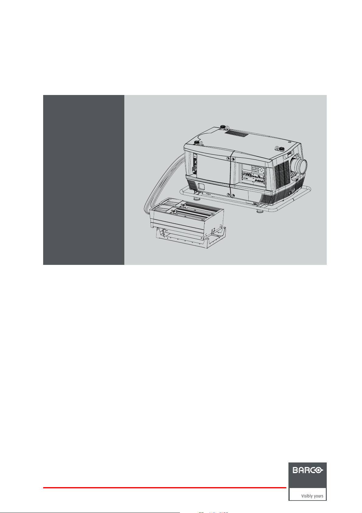
HDF WLP series
User and Installation manual
R5906730/05
01/08/2017
Page 2

Barco NV
President Kennedypark 35, 8500 Kortrijk, Belgium
Phone: +32 56.36.82.11
Fax: +32 56.36.883.86
Support: www.barco.com/en/support
Visit us at the web: www.barco.com
Printed in Belgium
Page 3

Changes
Barco provides this manual ’as is’ without warranty of any kind, either expressed or implied, including but not limited to the implied warranties or merchantability and fitness for a particular purpose. Barco may make improvements and/or changes to the product(s) and/or the
program(s) described in this publication at any time without notice.
This publication could contain technical inaccuracies or typographical errors. Changes are periodically made to the information in this
publication; these changes are incorporated in new editions of this publication.
The latest edition of Barco manuals can be downloaded from the Barco web site w
h
ttps://www.barco.com/en/signin.
ww.barco.com or from the secured Barco web site
Copyright ©
All rights reserved. No part of this document may be copied, reproduced or translated. It shall not otherwise be recorded, transmitted or
stored in a retrieval system without the prior written consent of Barco.
EMC statements
EN55032/CISPR32 Class A MME (MultiMedia Equipment)
Warning : This equipment is compliant with Class A of CISPR 32. In a residential environment this equipment may cause radio interfer-
ence.
Class A ITE (Information Technology Equipment)
Warning : This is a class A product. In a domestic environment this product may cause radio interference in which case the user may be
required to take adequate measures.
Federal Communications Commission (FCC Statement)
This equipment has been tested and found to comply with the limits for a class A digital device, pursuant to Part 15 of the FCC rules.
These limits are designed to provide reasonable protection against harmful interference when the equipment is operated in a commercial
environment. This equipment generates, uses, and can radiate radio frequency energy and, if not installed and used in accordance with
the instruction manual, may cause harmful interference to radio communications. Operation of this equipment in a residential area may
cause harmful interference, in which case the user will be responsible for correcting any interference at his own expense
Changes or modifi cations not expressly approved by the party responsible for compliance could void the user’s authority to operate the
equipment
Guarantee and Compensation
Barco provides a guarantee relating to perfect manufacturing as part of the legally stipulated terms of guarantee. On receipt, the purchaser
must immediately inspect all delivered goods for damage incurred during transport, as well as for material and manufacturing faults Barco
must be informed immediately in writing of any complaints.
The period of guarantee begins on the date of transfer of risks, in the case of special systems and software on the date of commissioning,
at latest 30 days after the transfer of risks. In the event of justified notice of complaint, Barco can repair the fault or provide a replacement
at its own discretion within an appropriate period. If this measure proves to be impossible or unsuccessful, the purchaser can demand a
reduction in the purchase price or cancellation of the contract. All other claims, in particular those relating to compensation for direct or
indirect damage, and also damage attributed to the operation of software as well as to other services provided by Barco, being a component
of the system or independent service, will be deemed invalid provided the damage is not proven to be attributed to the absence of properties
guaranteed in writing or due to the intent or gross negligence or part of Barco.
If the purchaser or a third party carries out modifications or repairs on goods delivered by Barco, or if the goods are handled incorrectly,
in particular if the systems are operated incorrectly or if, after the transfer of risks, the goods are subject to influences not agreed upon in
the contract, all guarantee claims of the purchaser will be rendered invalid. Not included in the guarantee coverage are system failures
which are attributed to programs or special electronic circuitry provided by the purchaser, e.g. interfaces. Normal wear as well as normal
maintenance are not subject to the guarantee provided by Barco either.
The environmental conditions as well as the servicing and maintenance regulations specified in this manual must be complied with by the
customer.
Trademarks
Brand and product names mentioned in this manual may be trademarks, registered trademarks or copyrights of their respective holders.
All brand and product names mentioned in this manual serve as comments or examples and are not to be understood as advertising for
the products or their manufac
turers.
Page 4

Page 5

Table of contents
TABLE OF CONTENTS
1. Safety................................................................................................................. 7
1.1 General considerations............................................................................................................... 7
1.2 Important safety instructions ......................................................................................................... 9
1.3 Product safety labels ................................................................................................................ 11
1.4 High Brightness precautions: Hazard Distance(HD) ..............................................................................12
1.5 HD for fully enclosed projection systems ........................................................................................... 14
1.6 HD in function ofthe lens Throw Ratio(TR)........................................................................................15
1.7 Important warnings concerning HDF WLP series flight cases .....................................................................16
2. General..............................................................................................................17
2.1 Installation requirements .. ..........................................................................................................17
2.2 About the delivered packages.......................................................................................................18
2.3 Unpacking the projector .............................................................................................................20
2.4 HDF WLP series flight case.........................................................................................................21
2.5 Flightcase for cooler unit............................................................................................................ 22
2.6 Projector configurations.............................................................................................................22
2.7 Projectorair inlets and outlets.......................................................................................................26
3. Installation process...............................................................................................27
3.1 Installation process projector........................................................................................................ 27
3.2 Installation process stand alone cooler .............................................................................................27
3.3 Starting up and adjustingthesystem ...............................................................................................28
4. Physical installation ..............................................................................................29
4.1 Power connection . . .................................................................................................................29
4.2 Suspension of the HDF WLP series projector with rigging clamps ................................................................30
5. Remote control unit (RCU).......................................................................................33
5.1 RCUbattery installation.............................................................................................................33
5.2 RCU rugged case installation .......................................................................................................34
5.3 RCU XLR adaptor installation.......................................................................................................35
5.4 Using theXLRadaptor ofthe RCU .................................................................................................35
5.5 RCUusage possibilities .............................................................................................................36
6. Physical installation stand alone cooler ......................................................................37
6.1 Supported mounting position........................................................................................................37
6.2 Assembling the housing .............................................................................................................39
6.3 Mounting the housing on the frame .................................................................................................45
6.4 Preparing the stand alone frame.. ..................................................................................................47
6.5 Installing the brackets on the cooler housing.......................................................................................48
6.6 Mounting the cooler housing on the frame . ........................................................................................49
6.7 Insertthe cooler units ...............................................................................................................51
6.8 Mount the filters......................................................................................................................52
6.9 Cabling and tubing...................................................................................................................53
6.10 Mount protection grid for the LCM cooler modules (option)........................................................................53
7. Lenses...............................................................................................................55
7.1 Available lenses .....................................................................................................................55
7.2 Lens selection .......................................................................................................................56
7.3 Lens installation .....................................................................................................................57
7.4 Lens removal ........................................................................................................................58
7.5 Lens safety cable . . .................................................................................................................. 59
7.6 Lens shift, zoom & focus ... .........................................................................................................61
7.7 Scheimpflug adjustment.............................................................................................................62
8. Input & Communication..........................................................................................67
8.1 Introduction ..........................................................................................................................67
8.2 Input source connections. . . .........................................................................................................68
8.3 Communication connections ........................................................................................................70
9. Getting started.....................................................................................................75
9.1 RCU& Localkeypad................................................................................................................75
9.2 Terminologyoverview ...............................................................................................................75
9.3 Power on projector ..................................................................................................................77
9.4 Switching to standby ................................................................................................................80
9.5 Power off projector ..................................................................................................................80
9.6 StatusLEDs .........................................................................................................................80
9.7 Using theRCU....................................................................................................................... 81
9.8 ProjectorAddress.................................................................................................................... 82
9.8.1 Displaying and Programming addresses into the RCU . . ....................................................................82
9.8.2 Controlling the projector ......................................................................................................82
9.9 Sourceselection.....................................................................................................................83
9.10 Alignment of a table mount HDF WLP series projector ............................................................................84
R5906730 HDF WLP SERIES 01/08/2017
1
Page 6

Table of contents
9.11 Alignment of a ceiling mount HDF WLP series projector...........................................................................84
10. Software upgrade .................................................................................................87
10.1 How to upgrade the software .......................................................................................................87
10.2 Free download ofProjector Toolset.................................................................................................87
10.3 Software upgrade procedure........................................................................................................87
11. Quickset upadjustment.........................................................................................99
11.1 Textboxes ONor OFF .............................................................................................................. 99
11.2 Quick Lens Adjustment via LENS key ..............................................................................................99
11.3 Direct Lens Adjustment (RCU) .....................................................................................................101
11.4 Quickpicture in picture.............................................................................................................101
11.5 Quick language selection . . ........................................................................................................102
12. Start up of the adjustment mode ............................................................................. 105
12.1 About the adjustment mode ........................................................................................................105
12.2 Abouttheuseof theremotecontrol and thelocal keypad........................................................................105
12.3 Start up the adjustment mode ......................................................................................................105
12.4 Navigation and adjustments........................................................................................................106
12.5 Menu memory ......................................................................................................................107
12.6 Shortcut keys to the menus ........................................................................................................107
12.7 Test patterns in adjustment mode..................................................................................................107
12.8 Help information in adjustmentmode..............................................................................................108
13. Input ............................................................................................................... 109
13.1 Input menu overview ...............................................................................................................109
13.2 Start up the input menu ............................................................................................................110
13.3 Input Selection ......................................................................................................................110
13.4 AdvancedSettings..................................................................................................................111
13.4.1 About Input Setup............................................................................................................111
13.4.2 Input configuration ...........................................................................................................111
13.4.3 DVI - RGBinput..............................................................................................................111
13.4.4 SDI input .....................................................................................................................112
13.4.5 5 cable input. . ................................................................................................................114
13.4.6 HDMI - DisplayPort input (3D input module)................................................................................114
13.5 Input locking . .......................................................................................................................114
13.6 Minimum delay......................................................................................................................116
13.7 Native resolution....................................................................................................................116
13.8 No Signal ...........................................................................................................................118
13.8.1 Background color ............................................................................................................118
13.8.2 Background Logo ............................................................................................................118
13.8.3 Shutdownsettings ...........................................................................................................119
13.8.4 Shutdownretarding time.....................................................................................................119
13.8.5 Auto Dimming................................................................................................................119
13.9 EDID ................................................................................................................................120
13.9.1 Configure an input . . .........................................................................................................120
13.9.2 Create custom EDID file .....................................................................................................121
13.9.3 Delete a custom EDID file ...................................................................................................122
13.9.4 Delete all custom EDID file ..................................................................................................123
13.10 3D input.............................................................................................................................123
13.10.1 About 3D modes .............................................................................................................124
13.10.2 Activate 3D ...................................................................................................................126
13.10.3 Auto detection................................................................................................................127
13.10.4 Input type selection ..........................................................................................................128
13.10.5 3D second input..............................................................................................................129
13.10.6 L-R Synchronisation, field dominance.......................................................................................129
13.10.7 L-RSynchronisation, Invert3D sync out....................................................................................130
14. Image .............................................................................................................. 133
14.1 Image menu overview ..............................................................................................................133
14.2 Start up the Image adjustments . . ..................................................................................................134
14.3 Image settings ......................................................................................................................134
14.3.1 Contrast......................................................................................................................134
14.3.2 Brightness....................................................................................................................135
14.3.3 Saturation ....................................................................................................................136
14.3.4 Phase.........................................................................................................................136
14.3.5 Color temperature (fixedvalues) ............................................................................................137
14.3.6 Colortemperature(custom values) .........................................................................................139
14.3.7 InputBalance ................................................................................................................139
14.3.7.1 Introduction to Input Balance . . .......................................................................................139
14.3.7.2 Adjusting the input balance ...........................................................................................141
14.3.8 Imagesettings, defaults .....................................................................................................143
14.4 Aspect Ratio........................................................................................................................144
14.5 Timings..............................................................................................................................145
14.5.1 Source timings...............................................................................................................145
14.5.2 Advancedtimings,clamp delay - clamp width ..............................................................................146
14.6 Image File Services ................................................................................................................147
2
R5906730 HDF WLP SERIES 01/08/2017
Page 7

Table of contents
14.6.1 Files and file manipulations. .................................................................................................147
14.6.2 Manual Load file .............................................................................................................147
14.6.3 File Load Filter ...............................................................................................................148
14.6.4 Delete a file ..................................................................................................................148
14.6.5 Delete all custom files .......................................................................................................149
14.6.6 Rename custom files ........................................................................................................150
14.6.7 Copy custom file .............................................................................................................151
14.6.8 Image file service options, Load file.........................................................................................152
14.6.9 Image file service options, Auto Picture Alignment .........................................................................153
14.7 Save custom settings...............................................................................................................153
14.8 Splash image.......................................................................................................................153
15. Layout ............................................................................................................. 155
15.1 Layout menu overview .............................................................................................................155
15.2 Startup thelayoutadjustments ....................................................................................................155
15.3 Introduction .........................................................................................................................156
15.4 Main window . .......................................................................................................................156
15.4.1 Main window source selection...............................................................................................156
15.4.2 Main window size ............................................................................................................157
15.4.3 Main window position ........................................................................................................158
15.5 PiP window . ........................................................................................................................159
15.5.1 Introduction to PIP .. .........................................................................................................159
15.5.2 Picture in Picture activation..................................................................................................160
15.5.3 PiP window, source selection................................................................................................160
15.5.4 PiP window, Size ............................................................................................................161
15.5.5 PiP window, position . ........................................................................................................162
15.6 Layout File Services................................................................................................................163
15.6.1 Load layout file...............................................................................................................163
15.6.2 Rename layout file ...........................................................................................................164
15.6.3 Delete layout file .............................................................................................................165
15.6.4 Delete all layout files.........................................................................................................165
15.6.5 Copy or Save as layout file ..................................................................................................166
15.7 Lens behavior.......................................................................................................................167
16. Laser............................................................................................................... 169
16.1 Lasermenu overview...............................................................................................................169
16.2 Startup thelaser adjustments .....................................................................................................169
16.3 laserpower mode...................................................................................................................170
16.4 laserpower .........................................................................................................................170
16.5 Auto dimmingwhen onPause .....................................................................................................171
16.6 Auto dimming when No Signal .....................................................................................................171
16.7 Auto dimmingwhen Over-temperature ............................................................................................172
16.8 CLO mode (Constant light output mode) . . . .......................................................................................172
16.9 CLO targets.........................................................................................................................174
16.10 Laser power.........................................................................................................................174
16.11 Laser identification..................................................................................................................175
16.12 XY-axisadjustment.................................................................................................................175
17. Alignment......................................................................................................... 177
17.1 Orientation..........................................................................................................................177
17.2 Lens adjustment, zoom - focus . . . .................................................................................................177
17.3 Lens adjustment, shift ..............................................................................................................178
17.4 Lens adjustment, mid position .....................................................................................................179
17.5 Calbratelens at startup.............................................................................................................179
17.6 Calibrate lens.......................................................................................................................179
17.7 Warping .............................................................................................................................180
17.7.1 Aboutwarping................................................................................................................181
17.7.2 Warp activation - deactivation ...............................................................................................181
17.7.3 Startupmanual adjustment .................................................................................................182
17.7.4 Warp adjustment principle...................................................................................................182
17.7.5 Settingthewarping level..................................................................................................... 185
17.7.6 Warp adaptation steps.......................................................................................................185
17.7.7 Making selections and adjustments . . .......................................................................................186
17.7.8 Keystone correction workflow ...............................................................................................187
17.7.9 Linearity adjustment, workflow ..............................................................................................188
17.7.10 Selecting and changing the position of a specific point.....................................................................189
17.7.11 Scaling the image............................................................................................................189
17.7.12 Shifting the image............................................................................................................190
17.7.13 Rotating the image. . . ........................................................................................................190
17.7.14 Hardware Reset..............................................................................................................192
17.7.15 OSD opacity. . ................................................................................................................192
17.7.16 Warp file service, load file ...................................................................................................193
17.7.17 Warp file service, save to file................................................................................................194
17.7.18 Warp file service, saveas ...................................................................................................194
17.7.19 Warp file service, rename file................................................................................................195
17.7.20 Warp file service, delete file .................................................................................................195
R5906730 HDF WLP SERIES 01/08/2017
3
Page 8

Table of contents
17.7.21 Warp file service, delete all files.............................................................................................196
17.7.22 Warp board reset.............................................................................................................197
17.7.23 Warp board and values reset................................................................................................197
17.7.24 Alternative Side Keystone................................................................................................... 198
17.7.25 Alternative Side Keystone................................................................................................... 198
17.8 Blankingadjustment................................................................................................................198
17.9 Gamma .............................................................................................................................200
17.10 Internal patterns ....................................................................................................................200
17.11 Color space.........................................................................................................................201
17.12 Scenergix ...........................................................................................................................203
17.12.1 Introduction. . .................................................................................................................203
17.12.2 Preparations. . ................................................................................................................204
17.12.3 Scenergix activation .........................................................................................................204
17.12.4 Scenergix pattern ............................................................................................................204
17.12.5 Scenergix adjustment lines ..................................................................................................205
17.12.6 Data doubling ................................................................................................................205
17.12.7 White level adjustment (blending area) . . . ..................................................................................207
17.12.8 Black level adjustment.......................................................................................................209
17.12.9 Scenergix Reset .............................................................................................................212
17.13 3D Glasses .........................................................................................................................213
17.13.1 Dark time adjustment ........................................................................................................213
17.13.2 Left-right outputreference delay ............................................................................................215
17.13.3 3D Sync Loop Through ......................................................................................................216
17.13.4 Upper limit for triple or double flash.........................................................................................217
17.14 HighEnd Systems Mirror...........................................................................................................217
18. Projector Control ................................................................................................ 221
18.1 Projector Control menu overview ..................................................................................................221
18.2 Start up the projector control adjustments . . .......................................................................................222
18.3 Individual Projector Address .......................................................................................................222
18.4 Projector Common Address........................................................................................................223
18.5 Serial Communication ..............................................................................................................223
18.5.1 Baud rate setup..............................................................................................................223
18.5.2 Interface Standard ... ........................................................................................................224
18.6 Network .............................................................................................................................224
18.6.1 Introduction to a Network connection .......................................................................................225
18.6.2 WiredDHCPset up..........................................................................................................225
18.6.3 Wired IP address set up .....................................................................................................226
18.6.4 Wired subnet mask set up . ..................................................................................................227
18.6.5 Wireddefault gatewaysetup................................................................................................228
18.6.6 Wirelessnetwork activation.................................................................................................. 229
18.6.7 Wirelessaccess points selection and setup ................................................................................230
18.6.8 Wireless DHCP set up .......................................................................................................231
18.6.9 Wireless fixed IP address set up ... . . .......................................................................................232
18.6.10 Wireless subnet mask set up ................................................................................................233
18.6.11 Wireless default gateway setup.............................................................................................234
18.7 IRControl switching ................................................................................................................235
18.8 DMX.................................................................................................................................235
18.8.1 DMX address. ................................................................................................................236
18.8.2 DMX universe................................................................................................................ 236
18.8.3 DMX mode . . . ................................................................................................................237
18.8.4 Art-NetDMX..................................................................................................................238
18.8.5 FrontXLR output voltage control............................................................................................238
18.8.6 Monitor .......................................................................................................................239
18.8.7 DMX Shutdown ..............................................................................................................240
18.8.8 DMX Shutdownretardingtime...............................................................................................241
18.9 Buttons..............................................................................................................................241
18.9.1 Standby button ...............................................................................................................241
18.9.2 Shortcutkeys.................................................................................................................242
18.10 Menu position.......................................................................................................................242
18.11 Local LCD...........................................................................................................................243
18.12 Language selection. ................................................................................................................243
18.13 Scheduler ...........................................................................................................................244
18.13.1 Adda task to the list ......................................................................................................... 244
18.13.2 Edit a task....................................................................................................................247
18.13.3 Deletetask ...................................................................................................................248
18.13.4 Scheduler, on or off .. ........................................................................................................248
18.14 GSM Configuration, activation .....................................................................................................249
18.15 GSM Configuration, subscription ..................................................................................................250
18.16 SMS services.......................................................................................................................251
18.16.1 Request for notifications.....................................................................................................252
18.16.2 Request for information ......................................................................................................252
18.16.3 Lamp ignition admission..................................................................................................... 252
19. Service ............................................................................................................ 255
19.1 Startup theService menu..........................................................................................................255
4
R5906730 HDF WLP SERIES 01/08/2017
Page 9

Table of contents
19.2 Identification ........................................................................................................................255
19.3 Diagnosis ...........................................................................................................................256
19.3.1 Versions ......................................................................................................................256
19.3.2 Measurements ...............................................................................................................257
19.3.3 Logging.......................................................................................................................258
19.3.4 BoardId ......................................................................................................................259
19.3.5 Notification ...................................................................................................................260
19.3.6 Tilt sensor ....................................................................................................................260
19.4 InternalService Patterns ...........................................................................................................261
19.5 USB memory .......................................................................................................................265
19.6 ResetFormatter ....................................................................................................................265
19.7 Refill mode . . . .......................................................................................................................266
19.8 Save Custom Settings..............................................................................................................266
19.9 Auto Dimming when over-temperature ............................................................................................267
19.10 Time and Date ......................................................................................................................267
20. Preventative maintenance actions ........................................................................... 269
20.1 1 month maintenance actions ......................................................................................................269
20.2 3 month maintenance actions ......................................................................................................270
21. Maintenance procedures....................................................................................... 271
21.1 Replacement of the dust filteron thefront side ...................................................................................271
21.2 Replacement of the dust filteron thebottomside.................................................................................272
21.3 Check of the dust filter of the standalone cooling unit. . . ..........................................................................273
21.4 Vacuum cleaning of the dust filters ................................................................................................274
21.5 Washing and drying the dust filters ................................................................................................275
21.6 Cleaning the lens . . . ................................................................................................................276
21.7 Cleaning the exterior of the projector ..............................................................................................276
21.8 Inserting an input module . . ........................................................................................................277
22. Removal and installation of the projector covers ......................................................... 279
22.1 Removal ofthe frontcover.........................................................................................................279
22.2 Removal ofthe side cover..........................................................................................................280
22.3 Removal ofthe lightunit cover.....................................................................................................281
22.4 Removal of the input cover. ........................................................................................................281
22.5 Installation of the front cover.......................................................................................................282
22.6 Installation of the side cover .......................................................................................................283
22.7 Installation of the light unit cover...................................................................................................284
22.8 Installation of the input cover.......................................................................................................285
23. Environmental Information.................................................................................... 287
23.1 Disposalinformation................................................................................................................287
23.2 Turkey RoHS compliance ..........................................................................................................287
23.3 Hazards .............................................................................................................................287
23.4 Contact information.................................................................................................................288
A. Specifications ..................................................................................................... 289
A.1 Specifications of the HDF W30LP .................................................................................................289
A.2 Technical Regulations ..............................................................................................................290
B. Dimensions........................................................................................................ 291
B.1 Dimensions of the HDF series projector...........................................................................................291
B.2 Dimensions of the HDF WLP series flightcase ...................................................................................292
C. Standard source files ............................................................................................ 293
C.1 Table overview......................................................................................................................293
D. DMX chart .......................................................................................................... 297
D.1 DMX chart, Basic ...................................................................................................................297
D.2 DMX chart, Full.....................................................................................................................297
D.3 DMX chart, Extended...............................................................................................................298
E. Stacking HDF WLP series projectors ......................................................................... 301
E.1 StackingHDFWLP seriesprojectors ..............................................................................................301
E.2 Aligningstacked HDF WLP series projectors .....................................................................................303
R5906730 HDF WLP SERIES 01/08/2017
5
Page 10

Table of contents
6 R5906730 HDF WLP SERIES 01/08/2017
Page 11
1. SAFETY
About this chapter
Read this chapter attentively. It contains important information to prevent personal injury while installing and using your HDF series
projector. Furthermore, it includes several cautions to prevent damage to your HDF series projector. Ensure that you understand and
follow all safety guidelines, safety instructions and warnings mentioned in this chapter before installing and using the HDF series
projector. After this chapter, additional “warnings” and “cautions” are given depending on the procedure. Read and follow these
“warnings” and “cautions” as well.
Clarification of the term “HDF WLP series” used in this document
When referring in this document to the term “HDF WLP series” means that the content is applicable for following Barco products:
• HDF W LP (commercial name HDF W30LP)
Barco provides a guarantee relating to perfect manufacturing as part of the legally stipulated terms of guarantee. Observing the specification mentioned in this chapter is critical for projector performance. Neglecting
this can result in loss of warranty.
1.1 General considerations
1. Safety
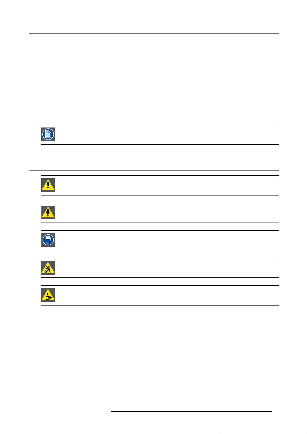
WARNING: Ensure you understand and follow all the safety guidelines, safety instructions, warnings and
cautions mentioned in this manual.
WARNING: Be aware of suspended loads.
WARNING: Wear a hard hat to reduce the risk of personal injury.
WARNING: Be careful while working with heavy loads.
WARNING: Mind your fingers while working with heavy loads.
General safety instructions
• Before operating this equipment please read this manual thoroughly and retain it for future reference.
• Installation and preliminary adjus
ers.
• All warnings on the projector and in the documentation manuals should be adhered to.
• All instructions for operating and use of this equipment must be followed precisely.
• All local installation codes should be adhered to.
tments should be performed by qualified Barco personnel or by authorized Barco service deal-
Notice on safety
This equipment is built in accordance w
UL60950-1 and CAN/CSA C22.2 No.60950-1, which are the safety standards of information technology equipment including
electrical business equipment. These safety standards impose important requirements on the use of safety critical components,
materials and insulation, in order
to live parts. Safety standards also impose limits to the internal and external temperature rises, radiation levels, mechanical stability
R5906730 HDF WLP SERIES 01/08/2017
to protect the user or operator against risk of electric shock and energy hazard and having access
ith the requirements of the international safety standards IEC60950-1, EN60950-1,
7
Page 12
1. Safety
and strength, enclosure construction and protection against the risk of fire. Simulated single fault condition testing ensures the
safety of the equipment to the user even when the equipment’s normal operation fails.
Notice on optical radiation
This projector embeds extremely high brightness (radiance) lasers; this laser light is processed through the projectors optical path.
Native laser light is not accessible by the end user in any use case. The light exiting the projection lens has been defused within the
optical path, representing a larger source and lower radiance value than native laser light. Nevertheless the projected light represents a significant risk for the human eye when exposed directly within the beam. This risk is not specific related to the characteristics
of laser light but solely to the high thermal induced energy of the light source; which is equivalent with lamp based systems.
Thermal retinal eye injury is possible when exposed within the Hazard Distance (HD). The HD is defined from the projection lens
surface towards the position of the projected beam where the irradiance equals the maximum permissible exposure as described in
the chapter “Hazard Distance”.
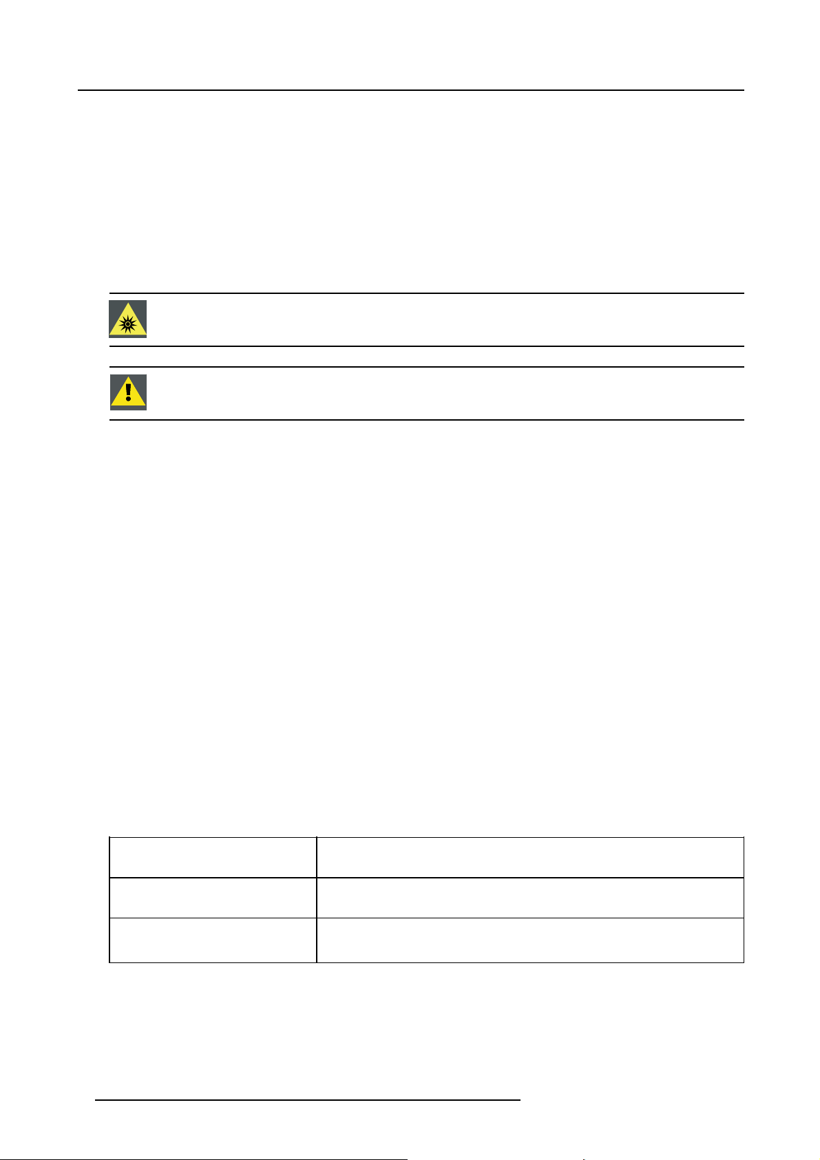
WARNING: No direct exposure to the beam within the hazard distance shall be permitted, RG3 (Risk Group
3) IEC 62471-5:2015
CAUTION: Use of controls or adjustments or performance of procedures other than those specified herein
may result in hazardous radiation exposure.
Restricted access location
This product may only be installed in a restricted access location. T
equipment where both of following applies:
he definition of a “restricted access location" is a location for
• Access can only be gained by SERVICE PERSONNEL or by OPERATORS who have been instructed about the reasons for
the restriction applied to the location and about the precautions that shall be taken.
• Access is through the use of the tool or lock and key, or other means of security, and is controlled by the authority responsible
for the location.
Why a restricted access location: This is a RG3 product. Based on international requirements, no person in allowed to enter the
projected beam within the zone between the projection lens and
by creating sufficient separation height or by placing optional barriers. Within the restricted area operator training is considered
sufficient. The applicable separation heights are discussed in "High Brightness precautions: Hazard Distance (HD)", page 12.
the related Hazard Distance (HD). This shall be physically impossible
Users definition
Throughout this manual, the term SERVICE PERSONNEL refers to persons having appropriate technical training and experience
necessary to be knowledgeable of potential hazards to which they are exposed (including, but not limited to HIGH VOLTAGE ELECTRIC and ELECTRONIC CIRCUITRY and HIGH BRIGHTNESS PROJECTORS) in performing a task, and of measures to minimize
the potential risk to themselves or other persons. The term USER and OPERATOR refers to any person other than SERVICE PERSONNEL, AUTHORIZED to operate professional projection systems.
A HDF WLP series projector is intended "FOR PROFESSIONAL USE ONLY" by AUTHORIZED PERSONNEL familiar with potential hazards associated with high voltage, high intensity light beams, ultraviolet exposure and high temperatures generated by the
lamp and associated circuits. Only qualified SERVICE PERSONNEL, knowledgeable of such risks, are allowed to perform service
functions inside the product enclosure.
Owner’s record
The part number and serial number are printed on a label which is stuck on the respective part. Record these numbers in the spaces
provided below. Refer to them whenever you call upon your Barco dealer regarding this product.
Product article number
Product serial number
Dealer
8 R5906730 HDF WLP SERIES 01/08/2017
Page 13

1.2 Important safety instructions
To prevent the risk of electrical shock
• This product should be operated from a mono phase AC power source.
• This apparatus must be grounded (earthed) via the supplied 3 conductor AC power cable. If none of the supplied power cables
are the correct one, consult your dealer.
If you are unable to insert the plug into the outlet, contact your electrician to replace your obsolete outlet. Do not defeat the
purpose of the grounding-type plug.
• The circuit breaker(s) that must be provided in the power circuit(s) of the projector is considered as general disconnect switch(es)
to switch off the complete installation.
• Do not allow anything to rest on the power cord. Do not locate this product where persons will walk on the cord. To disconnect
the cord, pull it out by the plug. Never pull the cord itself.
• Use only the power cord supplied with your device. While appearing to be similar, other power cords have not been safety
tested at the factory and may not be used to power the device. For a replacement power cord, contact your dealer.
• Do not operate the projector with a damaged cord. Replace the cord.
Do not operate the projector if the projector has been dropped or damaged - until it has been examined and ap
operation by a qualified service technician.
• Position the cord so that it will not be tripped over, pulled, or contact hot surfaces.
• If an extension cord is necessary, a cord with a current rating at least equal to that of the projector should be used. A cord rated
for less amperage than the projector may overheat.
• Never push objects of any kind into this product through cabinet slots as they may touch dangerous voltage points or short out
parts that could result in a risk of fi re or electrical shock.
• Do not expose this projector to rain or moisture.
• Do not immerse or expose this projector in water or other liquids.
• Do not spill liquid of any kind on this projector.
• Should any liquid or solid object fall into the cabinet, unplug the set and have it checked by qualified service personnel before
resuming operations.
• Do not disassemble this projector, always take it to an authorized trained service pe
• Do not use an accessory attachment which is not recommended by the manufacturer.
• Lightning - For added protection for this video product during a lightning storm, or when it is left unattended and unused for
long periods of time, unplug it from the wall outlet and disconnect media and communication cables. This will prevent damage
to the projector due to lightning and AC power-line surges.
rson when service or repair work is required.
1. Safety
proved for
To prevent fire hazard
• Do not place flammable or combustible materials near the projector!
• Barco large screen projection products are designed and manufactured to meet the most stringent safety regulations. This
projector radiates heat on its external surfaces and from ventilation ducts during normal operation, which is both normal and
safe. Exposing flammable or combustible materials into close proximity of this projector could result in the spontaneous ignition
of that material, resulting in a fire. For this reason, it is absolutely necessary to leave an “exclusion zone” around all external
surfaces of the projector whereby no flammable or combustible materials are present. The exclusion zone must be not less
than 40 cm (16”) for all projectors. The exclusion zone on the lens side must be at least 5 m. Do not cover the projector or the
lens with any material while the projector is in operation. Keep flammable and combustible materials away from the projector at
all times. Mount the projector in a well ventilated area away from sources of ignition and out of direct sun light. Never expose
the projector to rain or moisture. In the event of fire, use sand, CO
electrical fire. Always have service performed on this projector by authorized Barco service personnel. Always insist on genuine
Barco replacement parts. Never use non-Barco replacement parts as they may degrade the safety of this projector.
• Ensure no miss alignment can occur. Prolonged long time exposure of black wooden walls at close distance (< 20cm) can
represent a fire risk. After alignment the projector shall be securely mounted to the pedestal.
• Slots and openings in this equipment are provided for ventilation. To ensure reliable operation of the projector and to protect
it from overheating, these openings must not be blocked or covered. The openings should never be blocked by placing the
projector too close to walls, or other similar surface. This projector should never be placed near or over a radiator or heat
register. This projector should not be placed in a built-in installation or enclosure unless proper ventilation is provided.
• Projection rooms must be well ventilated or
• Let the projector cool down completely before storing. Remove cord from the projector when storing.
cooled in order to avoid build up of heat.
or dry powder fire extinguishers. Never use water on an
2
To prevent battery explosion
• Danger of explosion if battery is incorrectly installed.
• Replace only with the same or equivalent type recommended by the manufacturer.
• For disposal of used batteries, always consult federal, state, local and provincial hazardous waste disposal rules and regulations
to ensure proper disposal.
R5906730 HDF WLP SERIES 01/08/2017
9
Page 14

1. Safety
To prevent personal injury
• To prevent injury and physical damage, always read this manual and all labels on the system before powering the projector or
adjusting the projector.
• Do not underestimate the weight of the projector. The projector without the cooler weights ±100 kg (±225 lb.). To prevent
personal injury a hoisting tool should be used to lift the projector.
• To prevent injury, ensure that the lens, cooling system and all cover plates are correctly installed. See installation procedures.
• Warning: high intensity light beam. NEVER look into the lens ! High luminance could result in damage to the eye.
• Warning: extremely high brightness projector: This projector embeds extremely high brightness (radiance) lasers; this laser
light is processed through the projectors optical path. Native laser light is not accessible by the end user in any use case. The
light exiting the projection lens has been defused within the optical path, representing a larger source and lower radiance value
than native laser light. Nevertheless the projected light represents a significant risk for the human eye when exposed directly
within the beam. This risk is not specific related to the characteristics of laser light but solely to the high thermal induced energy
of the light source; which is equivalent with lamp based systems.
Thermal retinal eye injury is possible when exposed within the Hazard Distance. The Hazard Distance (HD) is defined from
the projection lens surface towards the position of the projected beam where the irradiance equals the maximum permissible
exposure as described in the chapter "High Brightness precautions: Hazard Distance (HD)", page 12.
• Based on international requirements, no person is allowed to enter the projected beam within the z
lens and the related Hazard Distance (HD). This shall be physically impossible by creating sufficient separation height or by
placing optional barriers. Within the restricted area operator training is considered sufficient. The applicable separation heights
are discussed in "High Brightness precautions: Hazard Distance (HD)", page 12.
• The projector shall be installed in a restricted access room equipped with a key or security lock preventing untrained persons
entering the Risk Group 3 use zone.
• Switch off the projector before attempting to remove any of the projector’s covers.
• Do not place this equipment on an unstable cart, stand, or table. The product may fall, causing serious damage to it and
possible injury to the user.
• Lenses, shields or screens shall be changed if they have become visibly d
impaired. For example by cracks or deep scratches.
• The associated Safety responsible of the unit must evaluate the setup before the unit may be started.
• Never point or allow light to be directed on people or reflective objects within the HD zone.
• All operators shall have received adequate training and be aware of the potential hazards.
• Strictly minimize the number of people who have access to the unit. The unit may never be operated without permission of the
responsible for safety.
• Do not put your hand or any body part in front of the beam.
Do not clean the port window when the projector is switched on.
• For a stand alone cooler, position the tubes so that they will not be tripped over, pulled, or contact hot surfaces.
amaged to such an extent that their effectiveness is
one between the projection
On servicing
• Do not attempt to service this product yourself, as opening or removing covers may expose you to dangerous voltage potentials
and risk of electric shock.
• Refer all servicing to qualified service personnel.
• Attempts to alter the factory-set internal controls or to change other control settings not specially discussed in this manual can
lead to permanent damage to the projector and cancellation of the warranty.
• Remove all power from the projector and refer servicing to qualified service technicians under the following conditions:
- When the power cord or plug is damaged or frayed.
- If liquid has been spilled into the equipment.
- If the product has been exposed to rain or water.
- If the product does not operate normally when the operating instructions are followed. Adjust only those controls that are
covered by the operating instructions since improper adjustment of the other controls may result in damage and will often
require extensive work by a qualified technician to restore the product to normal operation.
- If the product has been dropped or the cabinet has been damaged.
- If the product exhibits a distinct change in performance, indicating a need for service.
• Replacement parts: When replacement parts are required, be sure the service technician has used original Barco replacement
parts or authorized replacement parts which have the same characteristics as the Barco original part. Unauthorized substitutions may result in degraded performance and reliability, fire, electric shock or other hazards. Unauthorized substitutions may
void warranty.
• Safety check: Upon completion of any service or repairs to this projector, ask the service technician to perform safety checks
to determine that the product is in proper operating condition.
10
R5906730 HDF WLP SERIES 01/08/2017
Page 15
1. Safety
To prevent projector damage
• The air filters of the projector must be cleaned or replaced on a regular basis. Cleaning the booth area would be monthlyminimum. Neglecting this could result in disrupting the air fl ow inside the projector, causing overheating. Overheating may lead
to the projector shutting down during operation.
• The projector must always be installed in a manner which ensures free fl ow of air into its air inlets.
• If more than one projector is installed in a common projection booth, the exhaust air flow requirements are valid for EACH
individual projector system. Note that inadequate air extraction or cooling will result in decreased life expectancy of the projector
as a whole as well as causing premature failure of the lasers.
• In order to ensure that correct airflow is maintained, and that the projector complies with Electromagnetic Compatibility (EMC)
and safety requirements, it should always be operated with all of it’s covers in place.
• Slots and openings in the cabinet are provided for ventilation. To ensure reliable operation of the product and to protect it from
overheating, these openings must not be blocked or covered. The openings should never be blocked by placing the product
on a bed, sofa, rug, or other similar surface. This product should never be placed near or over a radiator or heat register. The
device should not be placed in a built-in installation or enclosure unless proper ventilation is provided.
• Ensure that nothing can be spilled on, or dropped inside the projector. If this does happen, switch off and remove all power
from the projector. Do not operate the projector again until it has been checked by qualified service personnel.
• Do not block the projector cooling fans or free air movement around the projector. Loose papers or other objects may not be
nearer to the projector than 10 cm (4") on any side.
• Proper operation of the projector can only be guaranteed in table mounting. It is not permitted to use the projector in another
position. See installation procedure for correct installation.
• Special care for Laser Beams: Special care should be used when projectors are used in the same room as high power laser
equipment. Direct or indirect hitting of a laser beam on to the lens can severely damage the Digital Mirror Devices
case there is a loss of warranty.
• Never place the projector in direct sunlight. Sunlight on the lens can severely damage the Digital Mirror Devices
case there is a loss of warranty.
• Save the original shipping carton and packing material. They will come in handy if you ever have to ship your equipment. For
maximum protection, repack your set as it was originally packed at the factory.
• Remove all power from the projectors mains terminals before cleaning. Do not use liquid cleaners or aerosol cleaners. Use a
damp cloth for cleaning. Never use strong solvents, such as thinner or benzine or abrasive cleaners, since these will damage
the cabinet. Stubborn stains may be removed with a cloth lightly dampened with mild detergent solution.
• To ensure the highest optical performance and resolution, the projection lenses are specially treated with an anti-reflective
coating, therefore, avoid touching the lens. To remove dust on the lens, use a soft dry cloth. For lens cleaning follow the
instructions precisely as stipulated in the projector manual.
• Rated maximum ambient temperature, t
• Rated humidity = 5% to 85% RH Non-condensed.
• An external frame must be used to stack projectors.
• For functionality and reliability, the projector requires accurate temperature control and cooling. Therefore a liquid cooling system is provided consisting of liquid circuits inside the projector which are connected via hoses to external coolers. Only cooler
models and hoses exclusively developed for this application and approved by Barco are allowed to be used.
• When using the projector with a stand alone cooler, do not stand on the cooling tubes or do not place any object on the tubes
so that free liquid flow can be guaranteed. Position the tu
=35°C(95°F).
a
bes so that there is no contact with hot surfaces.
TM
TM
in which
in which
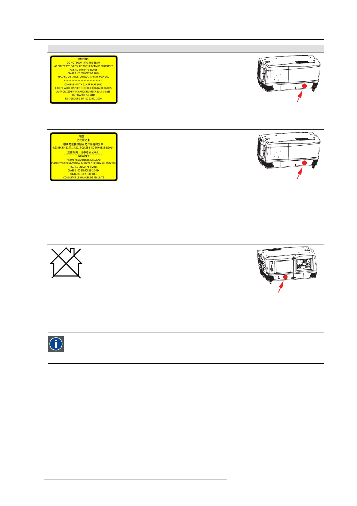
1.3 Product safety labels
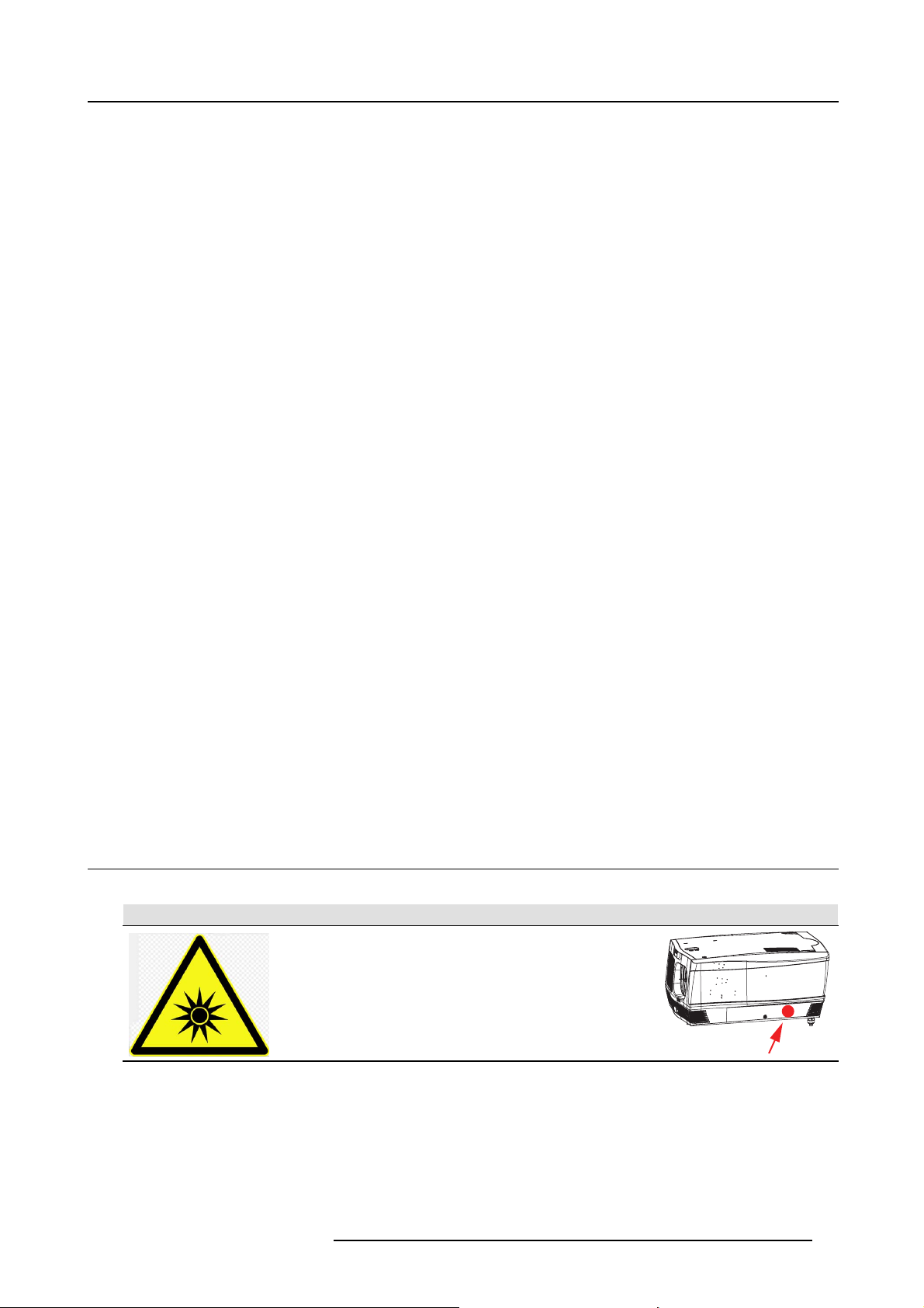
Light beam related safety labels
Label image Label description Label location
Hazard RG3: optical radiation warning symbol
R5906730 HDF WLP SERIES 01/08/2017 11
Page 16
1. Safety
Label image Label description Label location
WARNING! DO NOT LOOK INTO THE LIGHT BEAM
NO DIRECT EYE EXPOSURE TO THE BEAM IS
PERMITTED
RG3 IEC EN 62471–5:2015
CLASS 1 IEC EN 60825–1:2014
HAZARD DISTANCE: CONSULT SAFETY MANUAL
COMPLIES WITH 21 CFR 1040 EXCEPT WITH
RESPECT TO THOSE CHARACTERISTICS
AUTHORIZED BY VARIANCE NUMBER 2014-V-0285
DATED APRIL 14, 2016 RISK GROUP 3 LIP IEC
62471:2006
警告!
勿观看光束
眼睛勿直接接触可允许暴露的光束
(RG3 IEC EN 62471-5:2015 CLASS 1 IEC EN
60825-1:2014)
危害距离:请参考
安全手册
DANGER !
NE PAS REGARDER LE FAISCEAU EVITER TOUTE
EXPOSITION DIRECTE DES YEUX AU FAISCEAU
RG3 IEC EN 62471-5:2015
CLASS 1 IEC EN 60825-1:2014
DISTANCE DE SECURITE : CONSULTER LE MANUEL
DE SECURITE
Hazard RG3: not for household use symbol
1.4 High Brightness precautions: Hazard Distance (HD)
HD
Hazard Distance (HD) is the distance measured from the projection lens at which the intensity or the energy per surface
unit becomes lower than the applicable exposure limit on the cornea or on the skin. The light beam is considered (to
be) unsafe for exposure if the distance from a person to t
Restriction Zone (RZ) based on the HD
The HD depends on the amount of lumens produced
of the lens Throw Ratio (TR)", page 15.
To protect untrained end users (as cinema visitors, spectators) the installation shall comply with the following installation requirements: Operators shall control access to the beam within the hazard distance or install the product at the height that will prevent
spectators’ eyes from being in the hazard distance. Radiation levels in excess of the limits will not be permitted at any point less than
2.0 meter (SH) above any surface upon which persons other than operators, performers, or employees are permitted to stand or less
than 1.0 meter (SH) lateral separation from any place where such persons are permitted to be. In environments where unrestrained
behavior is reasonably foreseeable, the minimum separation height should be greater than or equal to 3.0 meter to prevent potential
exposure, for example by an individual sitting on another individual’s shoulders, within the HD.
These values are minimum values and are based on the guidance provided in IEC 62471-5:2015 section 6.6.5.
The installer must understand the risk and apply protective measures based upon the hazard distance as indicated on the label and
in the user information. Installation method, separation height, barriers, detection system or other applicable control measure shall
prevent hazardous eye access to the radiation within the hazard distance.
12
by the projector and the type of lens installed. See next chapter"HD in function
he light source is less than the HD.
R5906730 HDF WLP SERIES 01/08/2017
Page 17
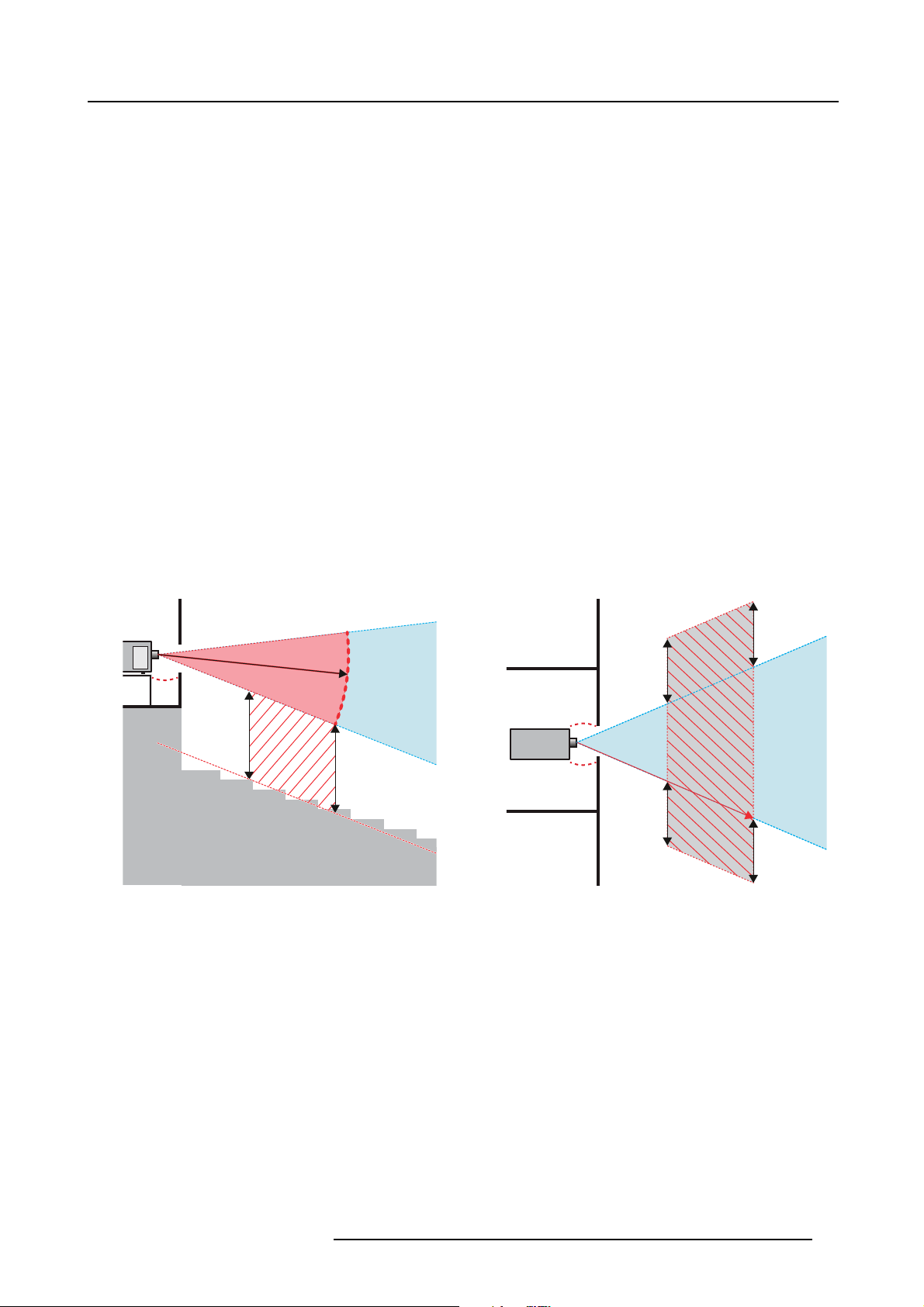
1. Safety
For example, projectors that have a HD greater than 1 m and emit light into an uncontrolled area where persons may be present
should be positioned in accordance with “the fixed projector installation” parameters, resulting in a HD that does not extend into
the audience area unless the beam is at least 2.0 meter above the floor level. In environments where unrestrained behavior is
reasonably foreseeable, the minimum separation height should be greater than or equal to 3.0 meter to prevent potential exposure,
for example by an individual sitting on another individual’s shoulders, within the HD. Sufficiently large separation height may be
achieved by mounting the image projector on the ceiling or through the use of physical barriers.
For LIPs (Laser Illuminated Projectors) installed in the USA market the above limits do not apply. Lip’s for installations other than in
cinema theaters shall be installed at a height vertically above the floor such that the bottom plane of the Hazard Zone shall be no
lower than 3 meters above the floor. Horizontal clearance to the hazard zone shall be 2.5 meters. Any human access horizontally
to the Hazard Zone, if applicable, shall be restricted by barriers. If human access is possible in an unsupervised environment, the
horizontal or vertical clearances shall be increased to prevent exposure to the RG3 hazard zone.
In addition for temporary installations (e.g.: rental and staging, lease, events …) the following requirements apply:
• This product can only be installed by Barco or sold or leased only to valid laser light show variance holders. In other words
our installers are required to have an approved laser light show variance. Such installers may currently hold a valid variance
for production of Class IIIb and IV laser light shows and/or for incorporation of the RG3 LIPs into their shows. Dealers and
distributors are also required to obtain a valid laser light show variance.
• This product shall be located in such a way that all propagating beam paths within the Restriction Zone, and the audience can
be directly observed at all times.
• Effects other than front or rear screen projections shall not be performed.
• Communication shall be maintained with other personnel assisting in surveillance of the LIP projection.
• In the event of any unsafe condition, immediately terminates (or designate the termination) of LIP projection light.
Install one or more readily accessible controls to immediately terminate LIP projection light. The power input at the projector side
is considered as a reliable disconnect device. When required to switch off the projector, disconnect the power cord at the projector
side. In case the power input at the projector side is not accessible (e.g. truss mount), the socket outlet supplying the projector shall
be installed nearby the projector and be easily accessible, or a readily accessible general disconnect device shall be incorporated
in the fixed wiring.
Laser light shows can be requested via the FDA online eSubmitter portal or via FDA Form FDA Form 3147 referencing to Barco’s
variance approval 2016-V-0144.
RA TH
TH
SW
HD
SW
RZ
RA
SH
RZ
PR
HD
SH
SW
1m
SW
(B) TOP VIEW(A) SIDE VIEW
Image 1-1
ASideview.
B Top view.
RA Restricted Access location (boot area of projector).
PR Projector.
TH Theater.
RZ Restriction Zone in the theater.
SH Separation Height.
SW Separation Width.
Based on national r
the related hazard distance (HD). This shall be physically impossible by creating sufficient separation height or by placing barriers.
The minimum separation height takes into account the surface upon which persons other than operator, performers or employees
are permitted t
On image 1-2 a typical setup is displayed. It must be verified if these minimum requirements are met. If required a restricted zone
(RZ) in the theater must be established. This can be done by using physical barrier, like a red rope as illustrated in image 1-2.
The restricted area sticker can be replaced by a sticker with only the symbol.
equirements, no person is allowed to enter the projected beam within the zone between the projection lens and
ostand.
R5906730 HDF WLP SERIES 01/08/2017
13
Page 18
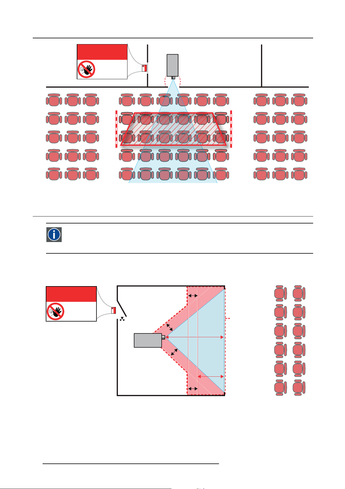
1. Safety
Image 1-2
RESTRICTED
AREA
AREA
PR
RESTRICTED
1.5 HD for fully enclosed projection systems
HD
Hazard Distance (HD) is the distance measured from the projection lens at which the intensity or the energy per surface
unit becomes lower than the applicable exposure limit on the cornea or on the skin. The light beam is considered (to
be) unsafe for exposure if the distance from a person to t
he light source is less than the HD.
Restriction Zone (RZ) based on the HD
The projector is also suitable for rear proje
in image 1-3 two areas should be considered: the restricted enclosed projection area (RA) and the observation area (TH).
RESTRICTED
ction applications; projecting a beam onto a defuse coated projection screen. As displayed
RA TH
sw
AREA
RESTRICTED
AREA
HDDIFFUSE
RZ
sw
PR
sw
PD
HD
REFLECTION
Image 1-3
RA Restricted Access location (enclosed projection area).
PR Projector.
TH Theater (observation area).
RZ Restriction Zone.
PD Projection Distance.
SW Separation Widt
h. Must be minimum 1 meter.
For this type of setup 3 different HD shall be considered:
14
sw
R5906730 HDF WLP SERIES 01/08/2017
Page 19
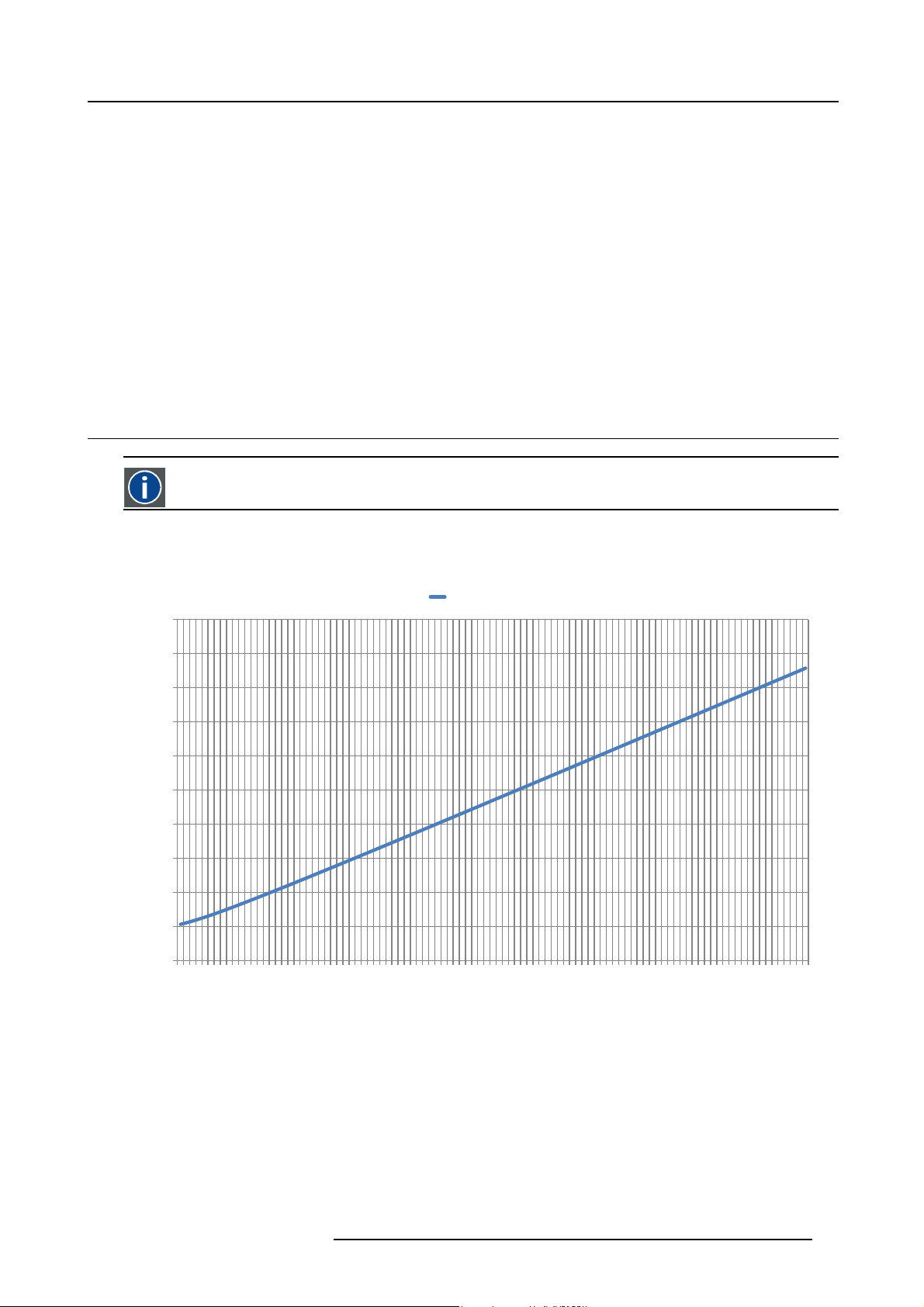
• HD as discussed in "High Brightness precautions: Hazard Distance (HD)", page 12, relevant for intrabeam exposure.
•HD
•HD
As described in "High Brightness precautions: Hazard Distance (HD)", page 12, it is mandatory to create a restricted zone within
the beam areas closer than any NOHD. In the enclosed projection area the combination of two restricted zones are relevant: The
restricted zone of the projected beam toward the screen; taking into account 1 meter Separation Width (SW) from the beam onward.
Combined with the restricted zone related to the rear reflection from the screen (HD
separation.
The HD
projection screen. To determine the HD distance for the used lens and projector model see graphs in chapter "HD in function of the
lens Throw Ratio (TR)", page 15.
HD
reflection
The light emitted from the screen within the observation shall never exceed the RG2 exposure limit, determined at 10 cm. The
HD
diffuse
: the distance that has to be kept restrictive related to the reflected light from the rear projection screen.
reflection
: the relevant distance to be considered while observing the diffuse surface of the rear projection screen.
diffuse
); also taking into account a 1 meter lateral
reflection
distance equals 25% of the difference between the determined HD distance and the projection distance to the rear
reflection
= 25% (HD – PD)
can be neglected if the measured light at the screen surface is below 5000 cd/m² or 15000 LUX.
1.6 HD in function of the lens Throw Ratio (TR)
TR (Throw Ratio)
The ratio of the distance to the screen (throw) to the screen width.
1. Safety
HDF series projector Hazard Distance
10
9
8
7
6
5
4
Hazard Distance HD [m]
3
2
1
0
1
1.3
1.6
1.9
2.2
2.5
2.8
3.1
Image 1-4
HD (in meter) in function of the Throw Ratio (TR)
3.4
3.7
4
4.3
4.6
HDF-W30LP
4.9
5.2
5.5
5.8
6.1
Throw Rao
6.4
6.777.3
7.6
7.9
8.2
8.5
8.8
9.1
9.4
9.7
10
10.3
10.6
10.9
11.2
R5906730 HDF WLP SERIES 01/08/2017 15
Page 20

1. Safety
1.7 Important warnings concerning HDF WLP series flight cases
Important warnings concerning stacking/transporting HDF WLP series rental flight cases
• Stack maximum two (2) HDF WLP series rental flight cases high. Never higher.
• Surface on which flight case is standing must be level to ensure that the total load is evenly spread out among the four wheels.
The surface must also be able to support the load safely.
• Before stacking or transporting flight cases, check the wheels and their fixation screws for wear or defects.
• Before stacking or transporting flight cases, check that the four lock handles on each flight case are in good working order and
locked securely.
• When stacked, make sure the wheels of the upper flight case are precisely positioned in the stacking dishes of the flight case
below.
•Stackedflight cases may not be moved. Before stacking, the lower flight case must already be in its final resting position before
placing the second upon it.
• Never stack loaded flight cases in a truck or other transport medium, unless each flight case is rigidly strapped tight.
• In the event of a wheel breaking, flight cases must be rigidly strapped tight to prevent a stack collapsing.
• Use an appropriate forklift to raise flight cases and take the necessary precautions to avoid personnel injury.
16
R5906730 HDF WLP SERIES 01/08/2017
Page 21

2. GENERAL
About this chapter
Read this chapter before installing your HDF WLP series projector. It contains important information concerning installation requirements for the HDF WLP series projector, such as minimum and maximum allowed ambient temperature, humidity conditions,
required safety area around the installed projector, required power net, etc.
Furthermore, careful consideration of things such as image size, ambient light level, projector placement and type of screen to use
are critical to the optimum use of the projection system.
About HDF WLP series projectors
This manual can be used for the following projectors :
• HDF W LP (commercial name HDF W30LP)
2.1 Installation requirements
Environmental conditions
The table below summarizes the physical environment in which the HDF series projector may be safely operated or stored.
2. General
Environment
Ambient Temperature
Air cleanliness
Humidity 5% to 85% RH Non-condensed 5% to 95% RH Non-Condensed
Altitude
Let the projector acclimatize after unpacking. Neglecting this may result in a startup failure of the Light Processor Unit.
Operating Non-Operating
10°C (50°F) to 35 °C (95 °F) -15°C (5°F) to 60°C (140°F)
Clean office environment (equivalent with cleanroom
standard ISO 14644-1 ISO Class 9)
-60 (-197Ft) to 3000m (9843Ft) -60 (-197Ft) to 10000m (32810Ft)
n.a.
Cooling requirements
For functionality and reliability, the projector requires accurate temperature control and cooling:
• External cooling circuit. The temperature control of the laser source is assumed by the external cooling unit. A liquid cooling
system is provided consisting of liquid circuits inside the projector which are connected via hoses to external coolers. Only
coolers and hoses exclusively developed for this a
• Internal cooling circuit. The internal temperature control is based on fans, which implies that the projector must be installed
with sufficient space around the projector head, minimum 10 cm (4 inch) to ensure sufficient air flow. It should be used in an
area where the ambient temperature, as measured at the projector air inlet , does not exceed +35 °C (95 °F).
pplication and approved by Barco are allowed to be used.
Clean air environment
A projector must always be mounted in a manner which ensures the free flow of clean air into the projectors ventilation inlets. For
installations in environments where the projector is subject to airborne contaminants such as that produced by smoke machines or
similar (these deposit a thin layer of greasy residue upon the projectors internal optics and imaging electronic surfaces, degrading
performance), then it is highly advisable and desirable to have this contamination removed prior to it reaching the projectors clean
air supply. Devices or structures to extract or shield contaminated air well away from the projector are a prerequisite, if this is not a
feasible solution then measures to relocate the projector to a clean air environment should be considered.
Only ever use the manufacturer’s recommended cleaning kit which has been specifically designed for cleaning optical parts, never
use industrial strength cleaners on the projector’s optics as these will degrade optical coatings and damage sensitive optoelectronics
components. Failure to take suitable precautions to protect the projector from the effects of persistent and prolonged air contaminants will culminate in extensive and irreversible ingrained optical damage. At this stage cleaning of the internal optical units will
be noneffective and impracticable. Damage of this nature is under no circumstances covered under the manufacturer’s warranty
and may deem the warranty null and void. In such a case the client shall be held solely responsible for all costs incurred during any
repair. It is the clients responsibility to ensure at all times that the projector is protected from the harmful effects of hostile airborne
particles in the environment of the projector. The manufacturer reserves the right to refuse repair if a projector has been subject to
knowingly neglect, abandon or improper use.
Main Power requirements
The HDF series projector operates from a nominal mono phase power net with a separate earth ground PE.
R5906730 HDF WLP SERIES 01/08/2017
17
Page 22
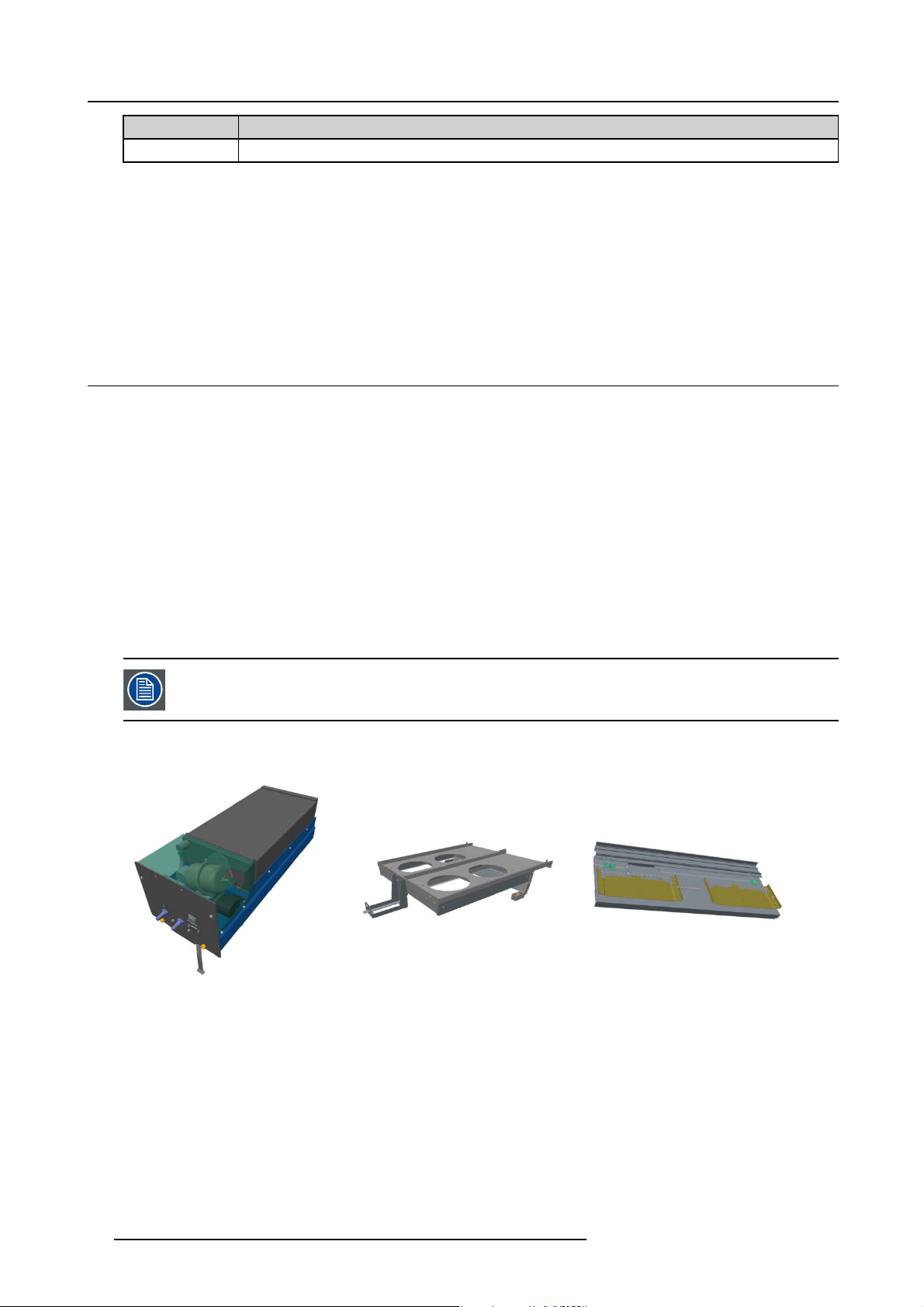
2. General
Projector Power requirements
HDF W30LP
The power cord required to connect the projector with the power net is delivered with the projector.
200-240 VAC, 50-60Hz, 15A at 200 VAC
Projector weight
Do not underestimate the weight of the HDF series projector. The projector weighs about ±100 kg (±225 lb.) without lens. Be sure
that the pedestal on which the projector has to be installed is capable of handling five (5) times the complete load of the system.
External cooling unit weight
The external cooling unit weighs about ±32 kg (±70.6 lb.).
2.2 About the delivered packages
General
The complete projection system is delivered in 2 packages.
•Projector
• Stand alone pack accessories.
The stand alone accessories contain the following content:
• 2 cooling units, each 1000W
• Cooling unit base plate
• Cooling unit housing
• 2 Cooling unit air filters
• Stand alone frame
• Stand alone hoses (4x) and cables (2x)
• Protection grid for cooling units
Overview
Image 2-1
Cooling unit
The stand alone cooler kit is available with 3 lengths of hoses: 8m (std), 5m and 2.5m.
Image 2-2
Base plate
Image 2-3
Cooling housing
18 R5906730 HDF WLP SERIES 01/08/2017
Page 23
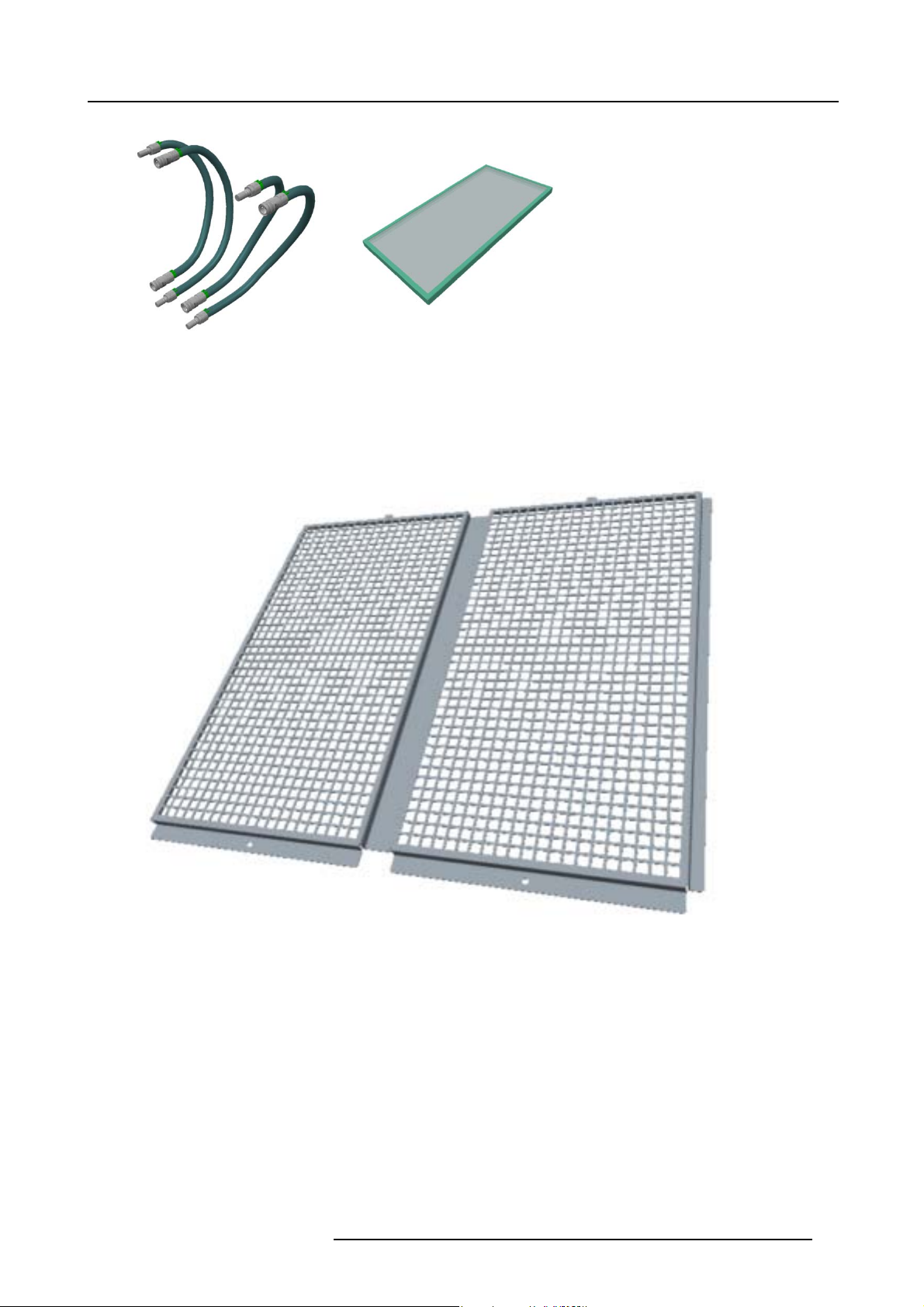
2. General
Image 2-4
Hoses
Image 2-5
Cooling fi lter
Image 2-6
Cooler protection grid
R5906730 HDF WLP SERIES 01/08/2017 19
Page 24
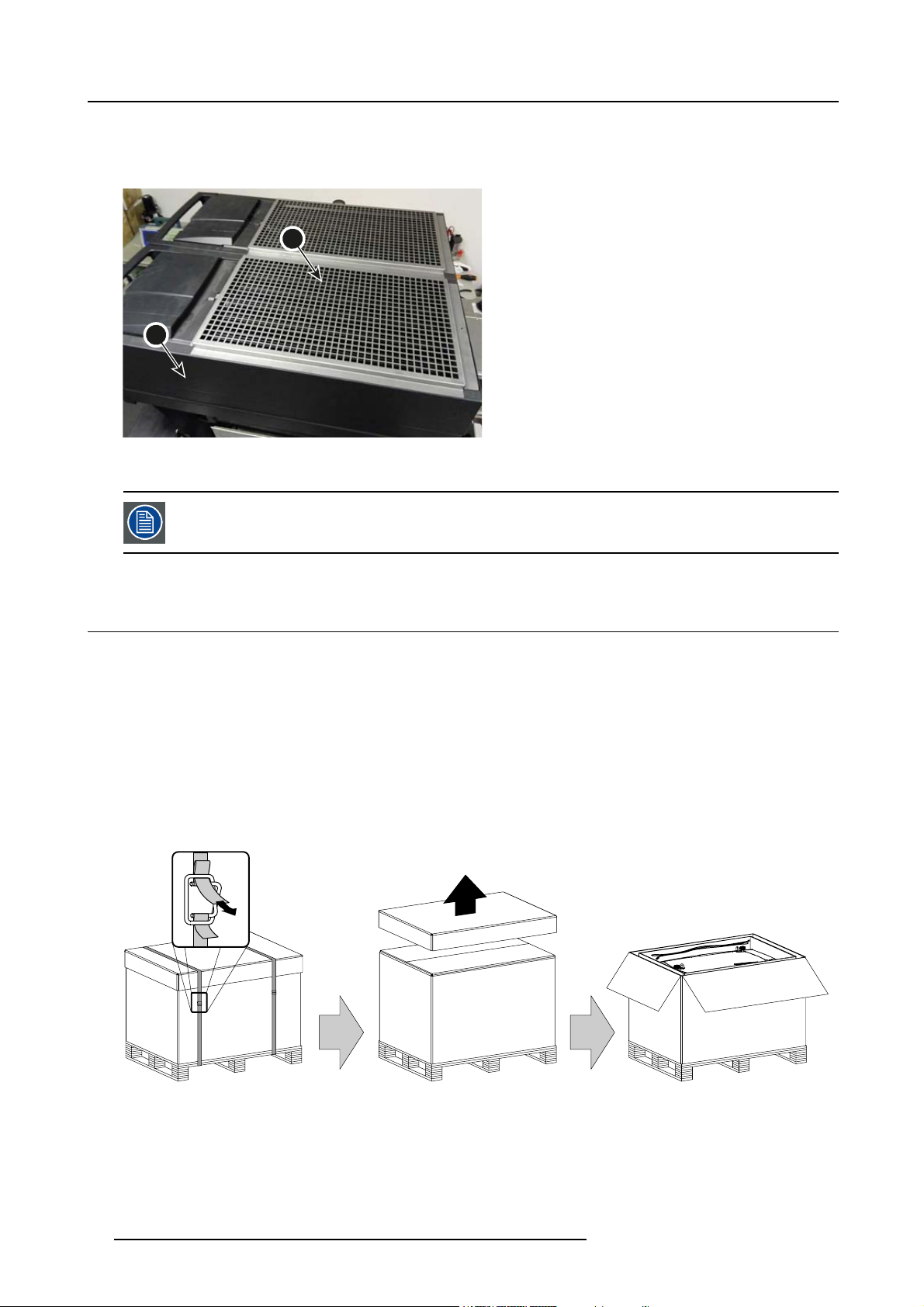
2. General
Option
The following optional accessory is available:
• A metal grid can be use to protect the radiators from damage due to direct blows or falling objects and such.
2
1
Image 2-7
1Cooler
2 Metal grid
This optional grid is delivered only in the Stand alone pack accessories. For further details, please see section
dedicated to the physical installation of the stand alone cooler.
2.3 Unpacking the projector
What has to be done ?
At delivery the projector is packed in a carton box upon a wooden pallet and secured with banding and fastening clips. Furthermore,
to provide protection during transportation, the projector is surrounded with foam. Once the projector is arrived at the installation
site, it has to be removed from the carton box and wooden pallet in a safe manner without damaging the projector.
Necessary tools
• Side cutter.
• 8 mm Allen key.
How to unpack the projector ?
1. Remove the banding around the carton box, by releasing the fastening clips as illustrated, and remove the top cover.
Image 2-8
2. Remove the power cord, which is attached to the packaging with a cable ties, and the two smaller carton boxes, located between
the inner carton sleeve and outer carton box.
Note: The two smaller carton boxes contain the manuals, the r emote control unit (RCU), two standard batteries size AA and
four rigging clamps for projector suspension.
20
R5906730 HDF WLP SERIES 01/08/2017
Page 25
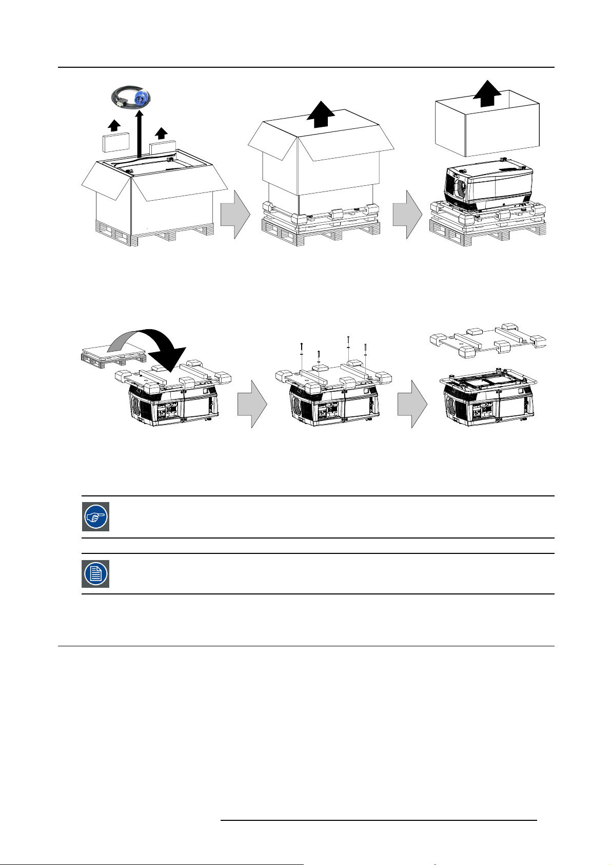
2. General
Image 2-9
3. Remove the carton box, the inner carton sleeve and the foam around the projector. See image 2-9.
Note: The projector is still attached to a wooden plate, which is detached from the below pallet.
4. Gently turn the projector upside down to gain access to the four bolts, which secure the projector. Note that this wooden plate is
detached from the pallet.
Tip: Lay a blanket (or the earlier re moved foam) on the floor to protect the projector h ousing form scratches while turning.
Image 2-10
5. Remove the wooden plate from the projector bottom, by releasing the four bolts. Use an 8 mm Allen key. See image 2-10.
6. Gently turn the projector back on its feet.
7. Remove the foam rubber around the carrying handl
Save the original shipping cardboard box and packing material. They will be necessary if you ever have to
ship your projector. For maximum protection, repack your projector as it was originally packed at the factory.
A plastic cap is placed into the lens opening of the projector. It’s recommended to reuse this plastic cap each
time you transport the projector. This to prevent intrusion of dust and foreign particles.
e.
2.4 HDF WLP series flight case
Introduction of the HDF WLP series flight case
The HDF WLP series flight case is designed to transport the HDF series projector in a safe and secure manner. The four caster
wheels, provided with breaks, and the eight handles make the HDF WLP series flight case easy to handle. The floor of the fl ight
case wagon is equipped with two small covered compartments to store the remote control and the rigging clamps. Furthermore,
three Velcro strips are attached to the bottom for fastening the power cord of the projector.
R5906730 HDF WLP SERIES 01/08/2017
21
Page 26
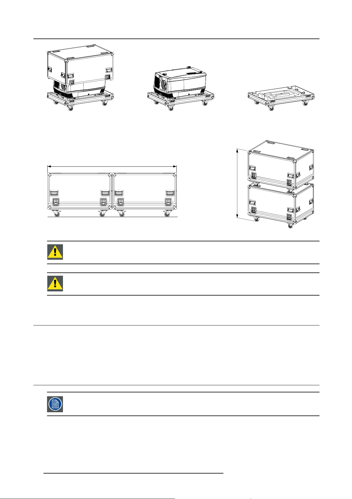
2. General
Image 2-11
HDF WLP series fl ight case (R9854510).
The dimensions of the HDF WLP series flight case are optimal for maximum utilization of the floor area of a truck. The cover of the
HDF WLP series flight case has four stacking dishes, which allows to stack the flight cases.
2400 mm
m
m
0
0
6
1
Image 2-12
WARNING: Maximum stack two (2) HDF series projector flight cases high. Never higher.
CAUTION: Prior to inserting projector in flight case turn in the adjustable feet and interlocking adapters fully.
2.5 Flight case for cooler unit
Introduction of the cooler unit fl ight case
It is recommended to use a flight case to ensure a safe and secure transportation of the external cooling unit of HDF series projector.
There is no flightcase explicitly dedicated for the cooler unit transportation, but the RLM W-series flight case, also provided by Barco,
can be use to fulfill this task.
2.6 Projector configurations
The drawings used in this chapter are not contractual. For convenience some options available in the HDF
WLP series projectors (e.g. standalone cooling unit in the laser version), are not shown here.
The different configurations
Depending on the installation the projector can be mounted in different ways, the 4 different configurations are:
22
R5906730 HDF WLP SERIES 01/08/2017
Page 27
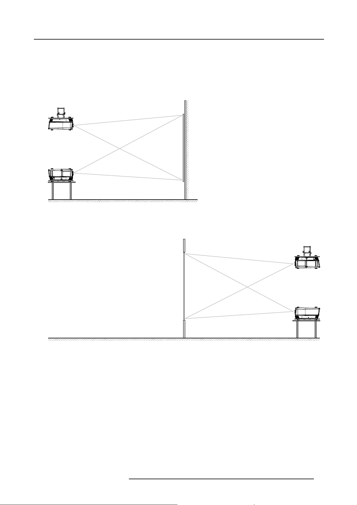
2. General
1. Front / Table (F/T)
2. Front / Ceiling (F/C)
3. Rear / Table (R/T)
4. Rear / Ceiling (R/C)
Front projection
The projector is installed, either in a table mount or ceiling mount configuration, at the same side of the screen as the audience.
AUDIENCE
F/C
F/T
Image 2-13
Front projection
FLOOR
SCREEN
Rear projection
The projector is installed, either in a table mount or ceiling mount configuration, at the other side of the screen opposite the audience.
AUDIENCE BACKSTAGE
R/C
N
E
E
Image 2-14
Rear projection
FLOOR
R
C
S
R/T
R5906730 HDF WLP SERIES 01/08/2017 23
Page 28
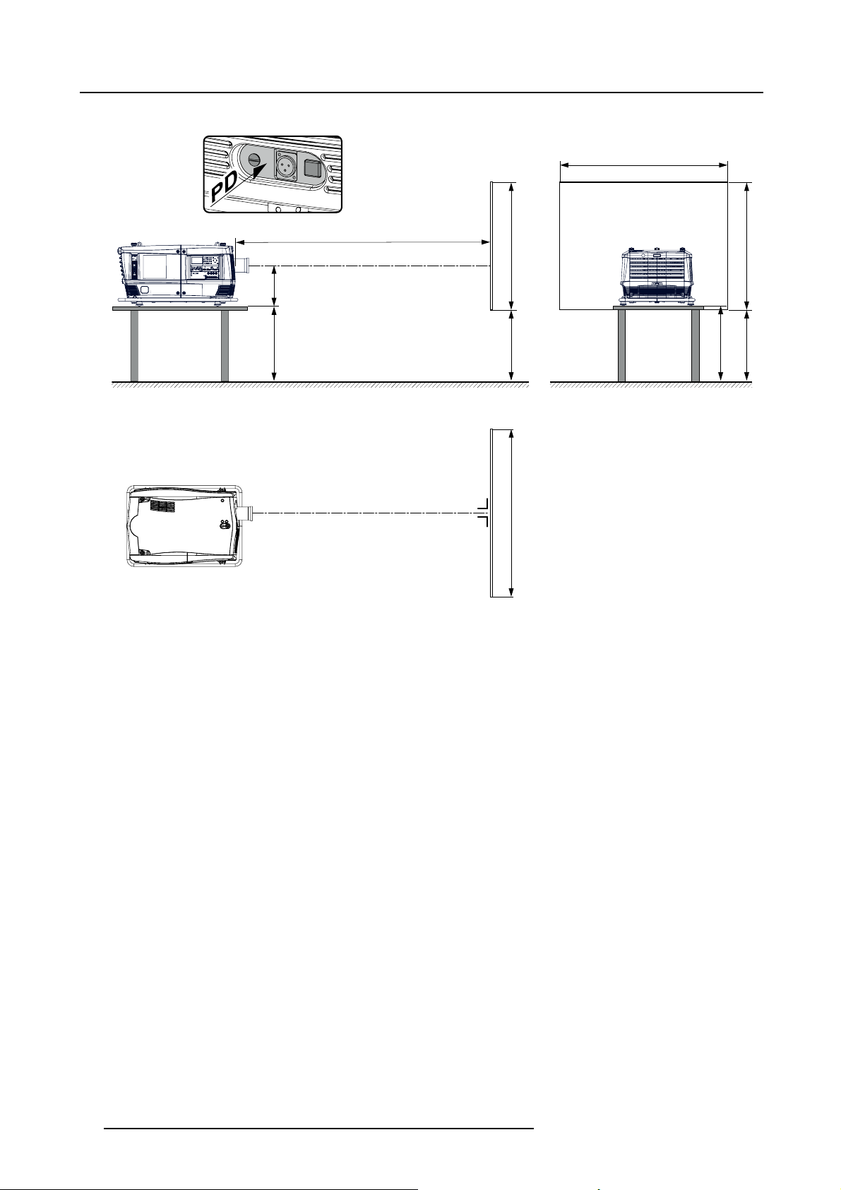
2. General
Positioning the projector
SW
PD
SCREENSCREEN
SHB
SHB
A
SCREEN
CD
FLOOR
CD
SW
Image 2-15
Projector positioning
The projector should be installed at right angles (horizontally and vertically) to the screen at a distance PD. Note the distance (A)
between lens centre and table surface is slightly variable. This distance (A) is nominal 35 cm in case all feet are turned in completely
and the vertical lens shift is set to zero (0).
On-Axis / Off-Axis projection
The position of the projector with reference to the screen may also be different depending on the installation. Basically the projector
can be positioned in On-Axis or Off-Axis configuration. On-Axis configuration means that the projector is positioned so as to have
the centre of the lens coinciding with the centre of the screen. Off-Axis projection is obtained by shifting the lens up, down, left or
right. Several parameters can be calculated determining the position in any installation.
Formula to calculate the distanc
e CD for On-Axis projection: CD=SH/2+B-A
Shift range
The lens can be shifted with respect to the DMD (P) which result in a shifted image on the screen (Off-Axis). A 100% shift means that
the centre point of the projected image is shifted by half the screen size. In other words, the centre point of the projected image falls
together with the outline of the image in an On-Axis projection. Due to mechanical and optical limitations it’s recommended to keep
the shift values within the field of view (F) as illustrated below. Within these shift ranges the projector and lens perform excellently.
Configuring the projector outside these shift ranges will result in a slight decline of image quality.
24
R5906730 HDF WLP SERIES 01/08/2017
Page 29
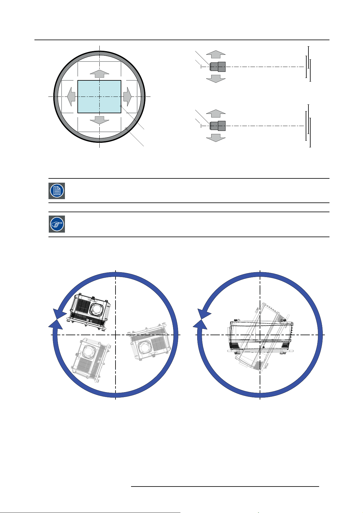
2. General
U
-50% +50%
L R
D
Image 2-16
Vertical and horizontal shift range
PDMD.
F Field of view.
It is mechanical possible to shift outside the recommended field of view, but it will r
quality depending on the used lens and the zoom position of the used lens. Furthermore, shifting too much
in both directions will result in a blurred image corner.
Best image quality is projected in the On-Axis configuration.
+120%
-20%
F
P
U
SIDE VIEW
D
F
P
P
L
TOP VIEW
+120%
-20%
-50%
R
F
esult in a decline of image
+50%
Horizontal and vertical projector tilt ranges
The projector can be rotated and mounted at any angle. In other words, you can tilt the projector as much as desired for your
application.
360°
360°
Image 2-17
R5906730 HDF WLP SERIES 01/08/2017 25
Page 30
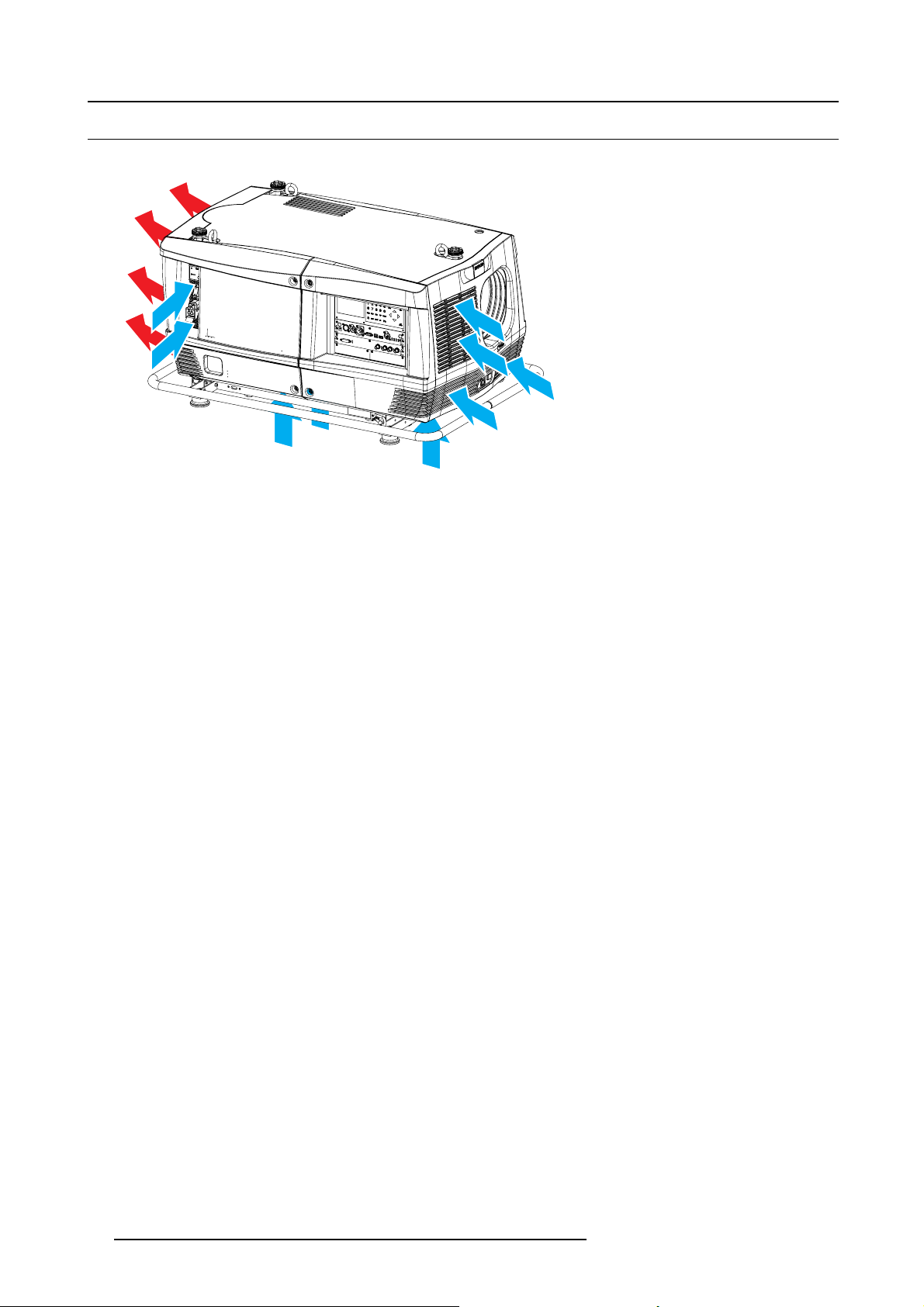
2. General
2.7 Projector air inlets and outlets
Air inlets and outlets
Image 2-18
Airflow
The HDF WLP series has 4 air inlet channels and one air outlet. The air outlet is located at the rear of the projector. The air inlets
are located at the front, bottom and right side of the projector.
26
R5906730 HDF WLP SERIES 01/08/2017
Page 31

3. Installation process
3. INSTALLATION PROCESS
About the installation process
The installation of the complete system is split up in two parts, installation of the projector and the installation of the cooling unit
(standalone pack).
Overview
• Installation process projector
• Installation process stand alone cooler
• Startingupandadjustingthesystem
3.1 Installation process projector
Check if all installation requirements are fulfilled such as the environment conditions of the installation area,
electrical facilities, etc. For more info see topic "Installation requirements", page 17.
Installation process from A to Z
The following steps describe briefly how to setup your HDF WLP series projector in a table mount front projection. Note that each
step refers to a corresponding procedure, which is more detailed and illustrated.
1. Install the batteries of the remote control. See "Remote control unit (RCU)", page 33.
2. Place the projector on a solid table in front of the screen at the expected throw distance. Ensure that the projector is installed at
right angles (horizontally and vertically) with the screen. See "Projector configurations", page 22.
3. Install the external stand alone cooler. To obtain an overview of the procedure, please see section bellow "Installation process
stand alone cooler", page 27. For more details refer to the complete description in chapter "Physical installation stand alone
cooler", page 37.
4. Select and install an appropriate lens, which covers the throw ratio ( = screen size / projector screen distance). See "Lenses",
page 55.
5. Connect the projector with the local power net. See "Power connection", page 29.
6. Connect your source to the appropriate input module. See "Input source connections", page 68
7. Update the software with the last version available on the Barco website. See "Software upgrade", page 87.
3.2 Installation process stand alone cooler
Installation process from A to Z
1. Assembling of the cooling box housing. The housing is delivered as a flat pack and should be assemble during the installation
process.
2. Mounting of the cooler housing on its support.
3. Mounting the empty cooler assembly on the stand alone frame.
4. Insert the cooler units and filters.
5. Establish the hose connections (4x) between the cooler and the projector. Connect also the four cables.
R5906730 HDF WLP SERIES 01/08/2017
27
Page 32

3. Installation process
3.3 Starting up and adjusting the system
Adjustment steps
1. Switch ON the projector. See "Power on projector", page 77
2. Select the input slot to which the source is connected. Do this by pressing the numeric key on the remote control unit or on the
local keypad, See "Source selection", page 83.
3. Zoom and shift the lens until the image is properly projected on the screen, Do this by using the “ZOOM” and “FOCUS” key on
the remote control unit or on the local keypad. If necessary, level the projector from side to side by tur
or out.
ning the adjustable feet in
28
R5906730 HDF WLP SERIES 01/08/2017
Page 33

4. PHYSICAL INSTALLATION
Overview
• Power connection
• Suspension of the HDF WLP series projector with rigging clamps
4.1 Power connection
CAUTION: Use only the power cord provided with the projector.
How to connect your projector with the local power net ?
1. Ensure that the power switch (S) stands in the “0” (OFF) position.
2. Connect the power cord (P) with the power input socket of the projector as illustrated below.
3. Secure the power plug by locking the plug holder clamp (H).
4. Connect the other end of the power cord with the local power net.
Caution: Ensure that the power net meets the power requirements of the projector.
The voltmeter (M) will immediately indicate the value of the mains voltage as soon as the projector is connected with the power
net.
4. Physical installation
M
M
P
P
S
S
1
H
H
2
Image 4-1
Power connection
Fuses
The projector is protected with an automatic circuit breaker of 35 A which is built in into the power switch.
Volt meter
After few moments, when the projector is fully started up, check if the value indicated by the volt meter is still within the specified
power range of the projector. Note that in case the power net drops significantly during start up, the light source will fail the ignite. If
this is the case, take the necessary measures to reinforce the power net to the projector before starting up the projector again.
Volt meter is protected with a Miniature Fuse, 5 x 20 mm, T 1AH, 250 VAC, UL: 115 V - 300 VDC.
Spare power plug
The projector is delivered with a spare
the cover of the light source first to access this spare power plug. Note that only qualified technical personnel may install a new
power plug.
power plug. This spare power plug is attached behind the nameplate of the projector. Remove
R5906730 HDF WLP SERIES 01/08/2017
29
Page 34

4. Physical installation
21
PE
Image 4-2
Pin configuration power plug HAN Q4/2 + PE.
43
LN
HAN Q4/2 +
4.2 Suspension of the HDF WLP series projector with rigging clamps
Rigging points and rigging clamps
The carrying handle, at the bottom side of the projector, is provided with eight slots. Four s
four slots are transversely (B) oriented. Each slot contains a rigging point of which the position in the slot can be adjusted depending
on the size of the truss installation. The rigging clamps (C) can be attached to those rigging points, which allows an easy and fast
physical setup of the projector in a hanging configuration.
A
B
lots are longitudinally (A) oriented and
C
Image 4-3
Rigging points
Necessary tools
• 24 mm open ended spanner.
• 17 mm open ended spanner.
Necessary parts
• Four rigging clamps (R820411).
• Safety chains.
How to install and to use the rigging clamps ?
1. Measure the distance, center tube as reference, between the two used support bars of the truss.
X mm
Image 4-4
2. Turn the projector upside down
secure this position. To release the nuts of the rigging points use a 24 mm open ended spanner. Ensure that the rigging points
are symmetrically lined up, so that the projector will hang in balance.
Warning: Be careful while working with
Warning: Always secure the rigging points after adjus tment.
and slide the rigging points on there place in the slots, according the measured distance and
heavy loads.
30
R5906730 HDF WLP SERIES 01/08/2017
Page 35

4. Physical installation
X mm
N
Image 4-5
Rigging points, distance
3. Turn in the rigging clamps (A) into the rigging points using a 17 mm open ended spanner and secure the rigging clamps by turning
the safety nut (B) on the rigging clamp against the rigging point using a 17 mm open ended spanner.
Warning: Always use four (4) rigging points, equally spread, to suspend the projector.
A
B
B
Image 4-6
Mounting clamps
4. Place all four rigging clamps in open position as illustrated.
Image 4-7
Opening clamps
5. Place the projector (upside down) under the truss installation and lower the truss until the support bars of the truss are nearby
the rigging clamps mounted on the pr
ojector.
R5906730 HDF WLP SERIES 01/08/2017
31
Page 36

4. Physical installation
Image 4-8
Lowering and mounting truss bar
6. Lift up the projector and hook the four rigging clamps over the support bars of the truss.
7. Lock all four rigging clamps.
8. Install a safety chain (S) around both sides of the carrying handle a
nd around the truss.
S
Image 4-9
Mounting Safety chains
Warning: Install the safety chain in that way that the projector cannot drop more than 20 cm.
9. Lift up the truss with attached projec
tor to the desired height.
Proceed with the alignment procedure, see "Alignment of a ceiling mount HDF WLP series projector", page
84.
S
32 R5906730 HDF WLP SERIES 01/08/2017
Page 37

5. Remote control unit (RCU)
5. REMOTE CONTROL UNIT (RCU)
Introduction
The remote control unit (A) of the HDF WLP series projector is equipped with a rugged case (B) and an XLR adaptor (C). The
remote control unit can be used wired via mini-jack or via rugged XLR. Note that the backlight, of the remote control unit, illuminate
continuously when wire connected.
A
B
C
Image 5-1
A Remote control unit (RCU).
B Rugged case.
C XLR adaptor.
Overview
• RCU battery installation
• RCU rugged case installation
• RCU XLR adaptor installation
• Using the XLR adaptor of the RCU
• RCU usage possibilities
5.1 RCU battery installation
Where to find the batteries for the remote control ?
The batteries are not placed in the remote control unit to avoid control operation in its package, resulting in a shorter battery life
time. At delivery the batteries can be found in a separated bag attached to the remote control unit. Before using your remote control,
install the batteries fi rst.
How to install the batteries in the remote control ?
1. Push the battery cover tab with the fingernail a little backwards (1) and pull, at the same time, the cover upwards (2).
1
2
Image 5-2
2. Insert the two AA size batteries, making sure the polarities match the + and - marks inside the battery compartment.
R5906730 HDF WLP SERIES 01/08/2017
33
Page 38

5. Remote control unit (RCU)
+
-
Image 5-3
3. Insert (1) the lower tab of the battery cover in the gap at the bottom of the remote control, and press (2) the cover until it clicks
in place.
+
-
2
1
-
Image 5-4
+
+
CAUTION: Replace with the correct battery type. Use two AA size batteries. There is a risk of explosion if the
battery is replaced with an incorrect type.
CAUTION: Replace the battery as explained above. There is a risk of explosion if the battery is incorrectly
installed.
5.2 RCU rugged case installation
How to install the rugged case of the remote c
1. Slide the bottom of the RCU into the rugged case and then pull the top of the rugged case over the top of the RCU as illustrated.
ontrol ?
Image 5-5
34 R5906730 HDF WLP SERIES 01/08/2017
Page 39

5.3 RCU XLR adaptor installation
Install the rugged case before installing the XLR adaptor. Vice-versa, remove the XLR adaptor before removing
the rugged case from the RCU.
Necessary tools
5mmflat screw driver.
How to install the XLR adaptor of the remote control unit ?
1. Push the XLR adaptor (C) upon the rugged case of the remote control unit as illustrated.
Note: Ensure that the text of the XLR adaptor is on top.
C
5. Remote control unit (RCU)
S
S
Image 5-6
2. Fasten the two screws (S) of the XLR adaptor. Turn each screw repeatedly one or two turns until both screws are tight.
5.4 Using the XLR adaptor of the RCU
How to use the XLR adaptor of the remote control unit ?
1. Connect a cable with XLR plug into the XLR adaptor.
2. Connect the other end of the cable with your HDF series projector.
3. Push the XLR adaptor completely against the rugged case of the remote control unit, as illustrated in the left image below, for
wired communication. Pull out the XLR adaptor (about 8 mm) to switch over to wireless communication.
Image 5-7
R5906730 HDF WLP SERIES 01/08/2017 35
Page 40

5. Remote control unit (RCU)
5.5 RCU usage possibilities
Summarized possibilities
Possibility description
Ref.
a.
RCU not wired
b.
RCU wired (mini-jack) Backlight illuminates continuously when wire is connected. Infra red
c.
RCU with rugged case not wired
d. RCU with rugged case wired (mini-jack) Backlight illuminates continuously when wire is connected. Infra red
e.
RCU with rugged case and XLR adaptor
pulled out “REMOTE” and not wired
f. RCU with rugged case and XLR adaptor
pulled out “REMOTE” and wired
g.
RCU with rugged case and XLR adaptor
pushed in “WIRED” and wired
abcd fge
Comment
disabled.
disabled.
The XLR adaptor must be in the pulled out position “REMOTE”, otherwise
the RCU will not function.
The RCU will send the commands via infra red to the projector.
The RCU will send the commands via the cable connected with the XLR
adaptor to the projector. Backlight illuminates continuously when wire
is connected. Infra red disabled.
Image 5-8
36 R5906730 HDF WLP SERIES 01/08/2017
Page 41

6. Physical installation stand alone cooler
A
B
C
6. PHYSICAL INSTALLATION STAND ALONE COOLER
Overview
• Supported mounting position
• Assembling the housing
• Mounting the housing on the frame
• Preparing the stand alone frame
• Installing the brackets on the cooler housing
• Mounting the cooler housing on the frame
• Insert the cooler units
• Mount the filters
• Cabling and tubing
• Mount protection grid for the LCM cooler modules (option)
6.1 Supported mounting position
General
The Standalone cooler can be positioned flat on a solid surface (Floor Mounting) or fixed onto the wall in portrait or landscape modes
(Wall mounting).
Image 6-1
A Wall Mounting (Landscape).
B Wall Mounting (Portrait).
C Floor Mo unting.
R5906730 HDF WLP SERIES 01/08/2017 37
Page 42

6. Physical installation stand alone cooler
Details and limitations
Depending the mounting option chosen, some limitations must be considered:
• Floor mounting: When this option is chosen, the cooler is installed on a fl at and stable surface, in horizontal position. Four
feet correctly distributed (2 on each side) allow stabilize the device. The cooler could be tilted forward or backward, but for
security reasons it is strongly recommended to let the unit in horizontal position, the best way to avoid the potential hazards of
falls and slips.
360°
1
Image 6-2
1 Fo ur feet allow stabilize the unit.
Stacking Standalone coolers: It is NOT allowed to stack multiple cooler modules on top of each other. The air intake of the
upper cooler would take in the “hot” air of the lower cooler, even at a distance of 1m apart.
x4
38
Image 6-3
A Stack of cooler positioned on their sides may be considered, but in this case, the direction of the entire coolers need to be
the same, in order to forcing air fl ow in the same direction.
Image 6-4
Note: This positioning must be secularized with an adapted structure.
R5906730 HDF WLP SERIES 01/08/2017
Page 43

6. Physical installation stand alone cooler
A B
A
B
• Wall mounting: When this option is chosen, the cooler must be fixed on the wall in portrait mode or in landscape mode.
In portrait mode, the cooler must be mounted with the cooling tubes up. The other position (cooling tubes down) is not authorized
because coolers are heavy (more or less 15kg) and if the safety clic fails and the cooler screw is not fixed, the cooler will simply
fall to the ground! In this orientation it is also less practical to remove a cooler for service.
Image 6-5
A Portrait Mode with cooling tubes to the top.
B Portrait Mode with cooling tubes down (not authorized)
In landscape mode the cooler must be mounted with the cooling tubes to the left. The other position (cooling tubes to the right)
is not authorized due to technical constraints. Functioning and lifetime of internal pump could be impacted if the unit is installed
in this position.
Image 6-6
A Landscape Mode with cooling tubes to the left (only one authorized position).
B Landscape Mode with cooling tubes to the right (not authorized).
6.2 Assembling the housing
Housing parts
The housing parts
R5906730 HDF WLP SERIES 01/08/2017
are delivered as a flat pack and should be mounted together at the customers side.
39
Page 44

6. Physical installation stand alone cooler
Image 6-7
1
1
2
3
4
Image 6-8
This fl at pack contains the following parts:
1 Top plate
2
Side covers
3
M4 Hex Screws
5
6
7
8
2
9
4M3HexScrews
5
Support for middle bracket
6Sidefixation
7
Position plate
8 Middle bracket
9 Front plate
40
R5906730 HDF WLP SERIES 01/08/2017
Page 45

overview:
8
9
Image 6-9
Necessary tools
• Allen wrench 2.5 mm
• Allenwrench3mm
6. Physical installation stand alone cooler
2
1
5
First, turn all the screws in the inserts before starting to assemble.
Into the drawings used in this procedure, orientation of the unit is indicative. Don’t hesitate to change the
unit orientation to facilitate the mounting of parts. By example, it could be more easy to lay flat the front plate
upon the table when you installing the both side covers.
How to assemble
1. Insert the side fixation on both side covers. Slide it in for about 4 cm.
Make sure you insert the side fixation for the left side cover on the opposite side.
Turn in a set screws (M3) on each side but do not fasten it yet.
R5906730 HDF WLP SERIES 01/08/2017
41
Page 46

6. Physical installation stand alone cooler
Image 6-10
2. Slide the front plate with both fixation brackets
Turn in the 4 set screws (M3) and tighten them fully until the brackets are pushed strongly against the ribs in the cover.
Note: There may be paint job markings left on the internal side of the side covers (e.g. in the grooves for the positioning pin).
These markings are no thread nor should
fully on both side covers.
they be mistaken for such.
42
R5906730 HDF WLP SERIES 01/08/2017
Page 47

6. Physical installation stand alone cooler
Image 6-11
3. Install the position plate onto the middle brack
Image 6-12
et as illustrated. Tighten the plate with an M4 hex screw.
4. Slide the middle bracket into the grooves of the front plate. Pay careful to orient the middle bracket like indicated in the drawing
below (the three holes at the below of the bracket must be placed at the opposite to the front plate). Turn in a set screw (M3) as
indicated in reference 1.
Tip: Put in plac e the screws, without tightening them, before slide the middle bracket. It is more easy to positioning the screws
when the middle bracket is not in p lace.
R5906730 HDF WLP SERIES 01/08/2017
43
Page 48

6. Physical installation stand alone cooler
Image 6-13
x 3
5. Slide both top plates as indicated into the grooves. Slide unti
brackets. Use one screw (M3) on each side of the top plates and tighten them fully until the brackets are pushed strongly against
the ribs in the cover and middle bracket.
Tip: Put in plac e the screws, without tightening them, before sli
when the top plates are not in place.
l you reach the position plate and the hole matches the hole in the
de the top plates. It is more easy to positioning the screws
Image 6-14
6. Hook the middle bracket support into the middle bracket.
Turn in the fixation screw (M4).
44 R5906730 HDF WLP SERIES 01/08/2017
Page 49

Image 6-15
The housing is ready to be mounted on the frame.
6. Physical installation stand alone cooler
6.3 Mounting the housing on the frame
Necessary tools
Allenkey3mm
How to mount
1. Place the housing on the cooler frame so that both positioning pins (1) on the housing match the notches in the frame.
1
2
Image 6-16
R5906730 HDF WLP SERIES 01/08/2017 45
Page 50

6. Physical installation stand alone cooler
2. Also make sure that the frame fits behind the clamp (2). If necessary, slide the clamp a little bit in the housing. Fixate the clamp
fully so that it fits behind the rib on the housing.
Drive in a screw (M3) to connect the clamp to the frame.
Repeat for the other side.
3. Place the support for the middle bracket on the frame as indicated.
Driveinthefixation screw (M4).
Image 6-17
4. On the front side, drive in the 2 screws (M4), one at the left and one at right.
1
46
Image 6-18
Note: Only the hole referenced 1 must be used. The other holes around are not used at this step of the procedure.
R5906730 HDF WLP SERIES 01/08/2017
Page 51

6. Physical installation stand alone cooler
6.4 Preparing the stand alone frame
Necessary tools
• Allenkey3mm
• Nut driver
Necessary parts
• Stand alone frame
• 4 feet (floor mounting option)
Floor mounting
To install the standalone cooler in fl oor mounting mode follow this procedure:
1. Mount the 4 feet in such a way that the frame can stand stable. E.g. 2 on each short side or 2 on each long side.
Image 6-19
2. Push the threat axle through one of the holes and secure with a washer and a nut.
Continue with "Installing the brackets on the cooler housing", page 48.
Wall mounting
To install the standalone cooler in wall mounting mode follow this procedure:
1. Place the stand alone frame against the wall (side indicated with 1) and mark the drilling hole. Any hole in the frame can be used
as fixation point but make sure to divide the fixation point over the complete frame.
It can be mounted in portrait mode (A) or in landscape mode (B).
Note: In portrait mode the coolers must be mounted with the cooling tubes up. In landscape mode the cooler must be mounted
with the cooling tubes to the left.
R5906730 HDF WLP SERIES 01/08/2017
47
Page 52

6. Physical installation stand alone cooler
A B
U
U
1
Image 6-20
1 Wal l side
U U brackets location
A Portrait mode
B Landscape mode
When mounting the cooler assembly, the U brackets which will be mounted on the housing must be fixed to the indicated position
(U) on the frame.
- For portrait mode the U brackets must be mounted on top (cooling tubes will be facing upwards) .
- For landscape mode the U brackets are mounted on the left side (cooling tubes will be facing to the left).
Continue with "Installing the brackets on the cooler housing", page 48.
1
6.5 Installing the brackets on the cooler housing
Necessary parts
• 2 front brackets (U-brackets)
• 2 equal rear brackets
• 4HexScrewsM5x8
• 4 Hex Screws M5x12
How to install the brackets
1. Fixate the U-bracket (on both sides) to the side of the cooler housing with 2 screws (M5x12).
Image 6-21
2. Fixate the rear brackets to the backside of the cooler housing with 2 screws (M5x8) each.
48
R5906730 HDF WLP SERIES 01/08/2017
Page 53

Image 6-22
6.6 Mounting the cooler housing on the frame
Necessary parts
• Cooler housing already assembled
• Frame
• 5HexScrewsM5x8
6. Physical installation stand alone cooler
At this step of the procedure, the frame is considered as being in its fi nal position, and already fixed, if the
wall mounting option has been chosen. See chapter dedicated to the standalone frame preparation.
How to mount
1. Place the housing on the frame.
1
3
3
2
Image 6-23
1 cooler housing
2Frame
3 cooler inputs
2. Fixate the first U-bracket to the frame with 2 screws (M5x8) as shown in the following drawing.
Note: The two U-Brackets are not fixed in same manner. Here, the concerned U-bracket, is situated in the lower left corner of
the housing when you look at the device on the side of the cooler inputs.
R5906730 HDF WLP SERIES 01/08/2017
49
Page 54

6. Physical installation stand alone cooler
Image 6-24
3. Fixate the second U-bracket to the frame with only one screws (M5x8) as shown in the following drawing. There is a space of
more or less 2 centimeters between the frame side and the bracket.
Note: The two U-Brackets are not fixed in same manner. Here, the c
the housing when you look at the device on the side of the cooler inputs.
oncerned U-bracket, is situated in the lower right corner of
+/- 2cm
Image 6-25
4. Fixate the bracket situated to the backside of the cooler housing with only one screws (M5x8) each.
Image 6-26
50 R5906730 HDF WLP SERIES 01/08/2017
Page 55

6. Physical installation stand alone cooler
6.7 Insert the cooler units
Necessary tools
Flat screwdriver
Before you start
Check if the two indicated screws (reference 1) are present. If it is the case, remove this screws.
The use of these screws may become necessary to fixate the cooler in the cooler assembly when the captive screws (reference 2)
does not work.
2
Image 6-27
How to mount
1. Slide the first cooler unit in the cooler housing.
2
1
1
Image 6-28
2. Slide the second cooler unit in the cooler housing.
3. Fixate both units by closing the both captive screws.
R5906730 HDF WLP SERIES 01/08/2017
51
Page 56

6. Physical installation stand alone cooler
6.8 Mount the filters
Necessary tools
Flat screw driver (if screws are too difficult to loosen by hand)
Necessary parts
2xfilters
How to insert
1. Turn out both screws and remove the cover plate.
Image 6-29
2. Slide in a filter.
Look to the airflow sticker for the correct orientation. Airflow is up.
Image 6-30
3. Place the cover plate back on its location and drive in both fixation screws by hand.
Note: Please, do n’t use any tool! O nly hand tighten these screws.
52
R5906730 HDF WLP SERIES 01/08/2017
Page 57

6.9 Cabling and tubing
Always connect the right cooler with right group of connector at the backside of the projector. Connect the
left cooler with the left group of connectors at the backside of the projector.
Tubing
Tube 1
Tube 2 1m
Tube 3
Tube 4 2m
6. Physical installation stand alone cooler
From projector connector plate To cooler
1f
2f
1m
1f
2m
2f
1f
1m 2f
Image 6-31
1a
1b
2m
2a
2b
1a
1b
1m
1f
2a
2b
2m
2f
Cabling
From projector connector plate To cooler
XLR cable 1 1a 1a
Control cable 1 1b 1b
XLR cable 1 2f 2m
Control cable 2 2b 2b
6.10 Mount protection grid for the LCM cooler modules (option)
General
An metal grid (with two fixing screws) is provided in the delivery package. This optional grid can be use to protect the radiators from
damage due to direct blows or falling objects and such.
2
Image 6-32
1 Metal grille
2 Fixation tabs
3Screws
R5906730 HDF WLP SERIES 01/08/2017 53
1
3
Page 58

6. Physical installation stand alone cooler
Addition of the metal grid will have a very slight impact to the cooling performance and hence the lifetime of
the laser light source. .
Necessary tools
Flat screwdriver
How to mount
1. Slide the grid (reference 1 image 6-32) in the fixation tabs (reference 2 image 6-32).
2. Fix the grid with the two fixation screws (reference 3 image 6-32).
54
R5906730 HDF WLP SERIES 01/08/2017
Page 59

7. LENSES
Overview
• Available lenses
• Lens selection
• Lens installation
• Lens removal
• Lens safety cable
• Lens shift, zoom & focus
• Scheimpflug adjustment
7.1 Available lenses
Available lenses for the HDF WLP series projector
7. Lenses
Image 7-1
R9801414: T LD+ zoom lens (0.8 - 1 .16 : 1)
Image 7-4
R9862005: TLD+ zoom lens (1.16 - 1.49 : 1)
Image 7-2
R9840776: TLD+ (1.16 : 1) fixed lens
Image 7-5
R9862010: TLD+ zoom lens (1.39 - 1.87 : 1)
Image 7-3
R9862000: TLD+ lens (0.67 : 1)
Image 7-6
R9862020: TLD+ zoom lens (1.87 - 2.56 : 1)
R5906730 HDF WLP SERIES 01/08/2017 55
Page 60

7. Lenses
Image 7-7
R9862030: TLD+ zoom lens (2.56 - 4.16 : 1)
Image 7-8
R9862040: TLD+ zoom lens (4.16 - 9.6 : 1)
7.2 Lens selection
How to select the right lens
1. Determine the required screen width (SW).
2. Determine the approximate position of the projector in the room.
3. Start up the Lens Calculator on the Barco website: h
the possible lenses for your confi guration.
The Lens Calculator window opens.
Image 7-9
R9829997: TLD+ zoom lens (9.6 - 10.39 : 1)
ttps://www.barco.com/en/media_entertainment/LensCalculator to determine
Image 7-10
Lens calculator
The Lens Calculator can also be used to determine the position of the projector when the lens type and screen
width is known.
Due to lens tolerances the results of calculated values may be different from measured values. These difference may vary +/- 5%.
56 R5906730 HDF WLP SERIES 01/08/2017
Page 61

7.3 Lens installation
How to install
1. Remove the plastic cap in the opening of the lens holder if not removed yet.
2. Take the lens assembly out of its packing material and remove the lens caps on both sides.
3. Place the lens holder in the “unlocked” position by moving the lens lock handle (A) towards the lens power supply socket (B) as
illustrated.
B
A
7. Lenses
Image 7-11
Lens installation, preparation
4. Ensure that the lens holder stands in the On-Axis position (horizontal and vertical mid position).
Note: The lens holder is placed default in the On-Axis position at factory.
5. Gently insert the lens in such a way that the lens connector matches the socket (B).
Image 7-12
Lens insertion
6. Insert the lens until the connector seats into the socket.
Warning: Do not release the Lens yet, as the Lens may fall out of the Lens Holder.
7. Secure the lens in the lens holder by sliding the lens lock handle into the “locked” position, which is away from the lens power
supply socket. Ensure the lens touches the front plate of the lens holder.
R5906730 HDF WLP SERIES 01/08/2017
57
Page 62

7. Lenses
Image 7-13
Lock lens
8. Check if the lens is really secured by trying to pull the lens out of the lens holder.
7.4 Lens removal
How to remove
1. Support the lens with one hand while you unlock the lens holder by sliding the lock handle towards the “unlocked” position as
illustrated.
Image 7-14
Lens removal, unlock
2. Gently pull the lens out of the lens holder.
Image 7-15
Lens removal
It’s recommended to place t
Lens to protect the optics of the Lens.
he Lens caps of the original Lens packaging, back on both sides of the removed
58 R5906730 HDF WLP SERIES 01/08/2017
Page 63

It’s recommended to place the plastic cap of the original projector packaging, back into the Lens opening to
prevent intrusion of dust.
7.5 Lens safety cable
When using the safety cable ?
The lens safety cable must be used in any circumstances to protect a mounted lens in the lens holder.
Configuration differences
Therearetwodifferentconfigurations for the safety cable. The configuration used depends on the used carrying handle or hoisting
eye.
•Configuration A applies when connecting the projector to the bottom carrying handle.
•Configuration B applies when connecting the projector to the hoisting eye.
Necessary parts
• Safety Cable (750 mm, Ø3 mm)
• Cable clamp M4
• Shackle 7x70 mm
• 4 x Cable clip (16x16 mm, Ø4 mm)
7. Lenses
How to mount the cable
1. Paste four cable clips on the lens as illustrated (reference 1). Orient the open side of the clips towards the front of the lens.
2
2
1
Image 7-16
2. Snap the first loop end of the safety cable into one of the following clips and let the loop end point downwards.
a) Configuration A: Use the upper clip on the side of the cable bundle (reference 2, image 7-16).
b) Configuration B: Use the upper clip on the non-wired side (reference 2, image 7-17).
3. Slide the rest of the cable around the lens counterclockwise. Click the cable into every clip it passes in this loop.
Note: Make su re the cable pas ses between the lens and the cable bundle.
4. Slide the cable through the loop end at the beginning of the cable.
Image 7-17
1
R5906730 HDF WLP SERIES 01/08/2017
59
Page 64

7. Lenses
Image 7-18
Example of configuration A
5. Install a U-bolt on the lens holder, with the open ends oriented outwards (reference 3). Make sure that both a part of the loop end
and the outgoing part of the safety cable are placed in the enclosure.
3
3
Image 7-19
Example of Configuration A
Image 7-20
Example of Configuration B
6. Close the U-bolt and tighten it.
Note: Make sure the safety cable is tightened around the lens before tightening the U-bolt nuts.
7. Place the shackle through the free loop end of the safety cable.
How to mount the cable
1. Place the lens in the lens holder, using the lens locking mechanism.
Caution: Always make sure the lens is really secured by trying to pull the lens out of the lens holder.
2. Lead the cable end with the shackle around one of the following carrying handles:
-Configuration A: Around the bottom carrying handle.
-Configuration B: Through the front hoisting eye on the top plate. Temporarily remove the shackle to allow the cable to slide
through the hoisting eye.
3. Snap the shackle to the straight part of the cable.
4. Secure the shackle by screwing the safety ring of the shackle over the open end.
60
R5906730 HDF WLP SERIES 01/08/2017
Page 65

7. Lenses
Image 7-21
Example using the bottom carrying handle
7.6 Lens shift, zoom & focus
Via Lens key
1. Press LENS key on the local keypad or the remote control.
The zoom/focus menu opens.
Image 7-23
Zoom/Focus adjustment
2. Use the ▲ or ▼ key to zoom the lens.
Use the ◄ or ► key to focus the lens.
Press ENTER to switch to Lens shift adjustment.
Image 7-22
Example using the hoisting eye
Image 7-24
Shift adjustment
3. Use the ▲ or ▼ key to shift the lens in vertical direction.
Use the ◄ or ► key to shift the lens in horizontal direction.
Press ENTER to switch to zoom/focus adjustment.
Via direct access keys on the remote control
1. Press LENS FOCUS button [-] or [+] (C) for an overall focus of the image.
2. Press ▲ LENS SHIFT ▼ button for correct vertical position of the image on the screen.
3. Press ◄ LENS SHIFT ► button for correct horizontal position of the image on the screen.
Take into account that the lens focus may slightly drift while the lens is warming up from cold to operation
temperature. This is a typical phenomenon for projection lenses used with high brightness projectors. The
operation temperature of the lens is reached after approximately 30 minutes projection of average video.
R5906730 HDF WLP SERIES 01/08/2017 61
Page 66

7. Lenses
7.7 Scheimpflug adjustment
Always use allowed and calibrated lenses for the specific projector while adjusting the Scheimplug adjustments.
What has to be done ?
The lens holder has to be adjusted so that the “sharp focus plane” of the projected image falls together with the plane of the screen
(Fp1→Fp2). This is achieved by changing the distance between the DMD plane and the lens plane (Lp1→Lp2). The closer the lens
plane comes to the DMD plane the further the sharp focus plane will be. It can sometimes happen that you won’t be able to get a
complete focused image on the screen due to a tilt (or swing) of the lens plane with respect to the DMD plane. This is also known
as Scheimpflug’s law. To solve this the lens plane must be placed parallel with the DMD plane. This can be achieved by turning the
lens holder to remove the tilt (or swing) between lens plane and DMD plane (Lp3→Lp4).
Lp1
Lp2
DMD
Image 7-25
Scheimpflug principle
Scheimpflug principle
The "plane of sharp focus" can be changed so that any plane can be brought into sharp focus. When the DMD plane
and lens plane are parallel, the plane of sharp focus will also be parallel to these two planes. If, however, the lens
plane is tilted with respect to the DMD plane, the plane of
optical properties. The DMD plane, the principal lens plane and the sharp focus plane will intersect in a line below the
projector for downward lens tilt.
Scheimpflug adjustment points
A
a
B
1
Fp1
SCREEN
Fp2
DMD
Lp3
Lp4
(Scheimpflug)
Fp4
Fp3
SCREEN
sharp focus will also be tilted according to geometrical and
b
2
4
Image 7-26
Scheimpflug adjustments
Indication on drawing Function
4 Locking nut
1, 2 and 3
A, B, C and D Set screws
a, b, c and d lock nuts
62
3
c
C
d
D
Scheimpflug adjustment nuts
R5906730 HDF WLP SERIES 01/08/2017
Page 67

1, 2 and 3 are adjustment points.
4 is a locking point and NOT used during Scheimpflug adjustment.
Necessary tools
• Allenkey3mm
• Nut driver 13 mm
• Nut driver 10 mm
How to adjust
1. Project a green focus pattern.
7. Lenses
Image 7-27
2. Loosen the lock nuts (a, b, c and d). See image 7-26.
3. Loosen the 4 set screws (A, B, C and D) by 1 cm. See image 7-26.
4. Fully loosen lock nut 4. See image 7-26.
5. Optimize the focus of the projected image as follows:
a) Place the zoom lens in TELE position (smallest projected image) and adjust the focus using the lens focus barrel or motorized
focus control.
b) Place the zoom lens in WIDE position (largest projected
c) Repeat steps “a” and “b” until the projected image is as sharp as possible.
image) and adjust the focus by turning equally on nut 1, 2 and 3.
R5906730 HDF WLP SERIES 01/08/2017
63
Page 68

7. Lenses
F
1
Image 7-28
Center focusing
6. Sharpen bottom left corner of the screen by adjusting nut 1.
2
3
F
1
Image 7-29
Left bottom focusing
7. Sharpen bottom right corner of the screen by adjusting nut 2.
64 R5906730 HDF WLP SERIES 01/08/2017
Page 69

Image 7-30
Right bottom focusing
8. Sharpen top right corner of the screen by adjusting nut 3
7. Lenses
F
2
F
3
Image 7-31
Corner focusing
9. Repeat from step 6 until the projected focus pattern is as sharp as possible in the center, left, right, top and bottom of the screen.
How to fixtheScheimpflug
Start the fixation as follows (steps must be followed strictly) :
1. Turn in set screw A, B and C. Tighten lightly (by hand).
Tip: Any movement of the im age will affect the S cheimp flug adjustment
2. Fasten lock nuts a, b and c.
3. Turn in set screw D lightly (by hand) allowing the image to move slightly (1/3 to 1/2 of a square).
R5906730 HDF WLP SERIES 01/08/2017
65
Page 70

7. Lenses
Image 7-32
4. Fasten lock nut d.
5. Tighten nut 4 until the offset of the image movement created in step 3 is canceled.
Tip: The amount of image move ment in s tep 3 will determ ine how tight the nut in step 5 will need to be turned to return the
image to its original position.
1/3 to 1/2
66
R5906730 HDF WLP SERIES 01/08/2017
Page 71

8. Input & Communication
8. INPUT & COMMUNICATION
Overview
• Introduction
• Input source connections
• Communication connections
8.1 Introduction
General
The Input & Communication side of the projector consists of a button module, a dual 3G/HDSDI and DVI-I input as standard input
module and 2 free input slots. The free input slots can be used for optional modules (e.g. 5-cable input).
1
2
3
4
5
6
7
8
Image 8-1
Input & Communication connections
1 Display
2
Optional antenna for Wifi connection
3 12 V output as power supply to external equipment
4 DMX in - out
5
XLR input port for remote control
6
RS232/RS422 input port
7
Dual Link DVI-I HDCP input
8 Free input slot
9 Button module
10
Optional antenna for GSM
11
RS232/RS422 input port
12 Ethernet port
13
Status and indication LEDs
14
USB port
15
3G/Dual/HDSDI input - output
16 Free input slot
9
10
11
12
13
14
15
16
R5906730 HDF WLP SERIES 01/08/2017
67
Page 72

8. Input & Communication
8.2 Input source connections
DVI and 3G/HDSDI input
This input module is standard delivered with the HDF WLP series projector.
DUAL LINK DVI-I HDCP
SEL
SYNC
INPUT
Image 8-2
Dual Link DVI and 3G/Dual HDSDI input
The yellow LED lights up when valid input sync is detected.
The green LED lights up when the input is selected.
DVI input specifications :
• RGB analog : up to 170 MHz.
• Single DVI : up to 165 MHz
• Dual link DVI : up to 210 MHz
DVI will not natively support 10-bit or 12-bit deep color. It is possible to enable 30-bit color over DVI using
a specific pixel packing. We support the pixel-packing that is implemented by Silicon Image Sil7189 DVI receiver.
3G/Dual HDSDI input specifications :
• 3G follows the SMPTE 425M standard.
• HDSDI follows he SMPTE 292M standard.
• Dual link follows the SMPTE 372M standard
• SDI follows the 259M standard
5-cable input (optional)
Optional multi purpose input which can be inserted in the free slots.
IN1
SEL
SYNC
3G/DUAL HDSDI
OUT1
IN2
SEL
SYNC
R9864000
OUT2
V/C
R
R9864010
SEL
SYNC
Image 8-3
BARCO
R/PR G/Y/VIDEO
5-CABLE INPUT
B/P
B
H/S
Signal connectivity
Input signal
RGBHV
RGBS
RGsB
RGBCV
Composite Video
Super Video
Component Video
R/P
R
R
R
R
R
—
—
PR/(R-Y)
G/Y/VIDEO B/ P
G
G
Gs
sync on green
G
VIDEO
Y
Luma
Y
BHV
B
B
B
———
——
PB/(B-Y) S
B
-S
Component Video
PR/(R-Y)
Ys
PB/(B-Y)
-SOY
YUV-CV R-Y Y B-Y CV
5-cable input specifications :
H/S V/C
S
R
—
——
CV
-
C
Chroma
—
——
-
68
R5906730 HDF WLP SERIES 01/08/2017
Page 73

8. Input & Communication
• Data and HD sources RGB and YUV [HS/VS, CS or SOG(Y)]:
- Pixel clock maximum 210 MHz
- 8 bit digital output
• Video sources CVBS, S-VIDEO, RGB and YUV [CS, CV or SOG(Y)]:
- PAL B/D/I/G/H, PAL60, PAL M, PAL N, PAL Nc
- NTSC M/J, NTSC 4.43
- SECAM B/D/G/K/L
- 525i, 625i, 525p, 625p
- Macrovision copy protection robust
- Standard images “video525” and “video625”
• Automatic detection of sync inputs but with manual override:
- automatic modes : RGB, YUV, VIDEO
- manual modes : RGB HS/VS - CS, RGB CV, RGB SOG, YUV HS/VS - CS, YUV CV, YUV SOY, CVBS, S-VIDEO
• Possible to disconnect 75 Ohm terminations on HS and VS (TTL sync level selection)
• Signal requirements:
- Component Video (BNC)
o
R-Y : 0,7Vpp ±3dB 75 Ohm termination.
o
Ys : 1Vpp ±3dB (0,7V Luma +0,3V Sync) 75 Ohm termination.
o
B-Y : 0,7Vpp ±3dB 75 Ohm termination.
-RG(s)B
o
R : 0,7Vpp ±3dB 75 Ohm termination.
o
G(s) : 1Vpp ±3dB (0,7Vpp G + 0,3Vpp Sync) 75 Ohm termination.
o
B : 0,7Vpp ±3dB 75 Ohm termination.
• Diagnostic LED’s on front panel:
- Green LED: Lights up in case input module is selected
- Yellow LED: Lights up in case sync detected
3D Input Module (optional)
Optional 3D input which can be inserted in the free slots.
BARCO
3D SYNC IN
Image 8-4
Signal connectivity
• 3D SYNC IN
BNC socket to apply an external 3D synchronization signal. Used for sequential modes. If signal is not present an internal 3D
sync is generated.
• DISPLAYPORT
DisplayPort connector to connect a video source.
• DisplayPort selection LED + sync LED
SEL: lights up if the DisplayPort is selected.
SYNC: lights up if the applied source has a valid DisplayPort sync.
• HDMI
Connector for HDMI cable (with optional locking mechanism).
• HDMI selection LED + sync LED
SEL: lights up if the HDMI input port is selected.
SYNC: lights up if the applied source has a valid HDMI sync.
• 3D SYNC OUT
BNC socket. Generates 3D synchronization signal to drive an infra red transmitter for active 3D glasses. In case an 3D synchronization signal is applied on the “3D SYNC IN” for a single channel 3D stream then the generated 3D output sync is derived
from this applied sync.
Input specifications
DISPLAYPORT HDMI
3D INPUT
SEL
SYNC
SEL
SYNC
R9864140
3D SYNC OUT
R5906730 HDF WLP SERIES 01/08/2017
69
Page 74

8. Input & Communication
• HDMI (High-Definition Multimedia Interface)
HDMI 1.4a up to 210MHz pixel clock. Support for ‘Deep Color’ up to 12 bit per color.
• DisplayPort
DisplayPort 1.1a up to 210 MHz pixel clock. Support for ‘Deep Color’ up to 12 bit per color.
In all cases, the minimum input frequency for 3D is 23 Hz per eye. Below this frequency the image will not be
displayed correctly.
8.3 Communication connections
Communication interface
DMX
IN
/1A
12V
1 2 3 4 5 6 7 8 9 10 11 12 13 14
Image 8-5
Communication interface, indications
1 12V 1A output
2
DMX interface (input, output)
3 XLR input
4
RS232 input
5
USB port
6 Ethernet port
7
Ethernet type indication
8 Ethernet activity indication
9 Error indication
10 Power indication
11 IR indication
12 Lamp indication
13
ACT (activity) indication
14
Wifi select indication
15 IR receiver
OUT
REMOTE CTRL
1
2
3
RS232/422 IN
USB
10/100 BASE-T
ETH
ACT
10/100
PWR LMP
ERR
WIFI
SEL
IR ACT
15
12V output
12 V output, maximum 1A, available when projector is not in stand by.
DMX interface
DMX is used as communication bu
the bus can be looped between the different devices. According the standard a five wire cable with XLR connector is used.
You can use the DMX input port to connect a DMX device (DMX console) to the projector. This way you can control the projector
from that DMX device (console). The DMX output port can be connected with the next device in the loop.
Pin Description
1Earth
70
s between different devices in the light technic. Each device has an input and an output, so that
R5906730 HDF WLP SERIES 01/08/2017
Page 75

8. Input & Communication
Pin Description
2
3Hot
4
5
DMX
DMX-512 Lighting protocol over RS-485 interface. Carries information of 512 channels from a lighting con
lighting devices. Standardized by USITT.
Cold
Return - (or not used)
Return + (or not used)
Wired remote control (XLR)
If desired the remote control unit can be wired and plugged in into the male XLR port on the communication interface.
XLR – Remote CTRL in
Pin Description
1
GND
2
RC5 in
3 XLR present sense
troller to
RS232/RS422 input
The communication interface of the HDF WLP series projector supports RS232 and RS422 serial communication on two different
types of input connectors. The left one a Sub-D connector, the right one an USBB connector acting as RS input when connected to
an USB input of a PC.
You can use the RS232/RS422 input to connect a local PC to your HDF WLP series projector. By this way you can configure and
control your HDF WLP series projector from your local PC.
Do not forget to set the projector’s baud rate to match that of the computer.
Advantages of using RS232/RS422 serial communicatio
• easy adjustment of the projector via PC (or MAC).
• allow storage of multiple projector configurations and set ups.
• wide range of control possibilities.
• address range from 0 to 255.
• sending data to the projector (update).
• copying data from the projector (backup).
RS232/422 input (Sub-D) port
Pin Description
1
DCD : Data Carrier Detect
2RXD-:ReceiveData
3 TXD- : Transmitted Data
4
DTR : Data Terminal Ready [RS232]
TXD+ : Transmitted Data [RS422]
5
GND : Ground
6
DSR : Data Set Ready [RS232]
RXD+ : Received Data [RS422]
7
— (not connected) —
8
CTS : Clear To Send
9 RI : Ring Indicator
n:
R5906730 HDF WLP SERIES 01/08/2017
71
Page 76

8. Input & Communication
RS232
An Electronic Industries Association (EIA) serial digital interface standard specifying the characteristics of the communication path between two devices using either D-SUB 9 pins or D-SUB 25 pins connectors. This standard is used for
relatively short-range communications and does not specify balanced control lines. RS-232 is a serial control standard
with a set number of conductors, data rate, word length and type of connector to be used. The standard specifies component connection standards with regard to computer interface. It is also called RS-232-C, which is the third version
of the RS-232 standard, and is functionally identical to the CCITT V.24 standard. Logical ’0’ is > + 3V, Logical ’1’ is < 3V. The range between -3V and +3V is the transition zone.
RS422
An EIA serial digital interface standard that specifies the electrical characteristics of balanced (differential) voltage,
digital interface circuits. This standard is usable over longer distances than RS-232. This signal governs the asynchronous transmission of computer data at speeds of up to 920,000 bits per second. It is also used as the serial port
standard for Macintosh computers. When the difference between the 2 lines is < - 0.2V that equals with a logical ’0’.
When the difference is > +0.2V that equals to a logical ’1’..
USB port
The communication interface is equipped with a master USB port, type “A” connector. This USB port will simplify the service procedures for software updates or for taking backup files from the projector without network connection. An USB-stick is plugged into
the USB port and files can be transferred from or to the projector using the local or remote control unit. Note that the USB-stick has
to be Linux FAT16 compatible.
Ethernet port
The projector can be connected to a LAN (local area network) using the Ethernet port on the communication interface. Once connected to the LAN, users are capable of accessing the projector from any location, inside or outside (if allowed) their company
network using the control software: Projector Toolset. This toolset locates the projector on the network in case there is a DHCP
server or the user can insert the correct IP-address of the projector to access the projector. Once accessed, it is possible to check
and manipulate all the projector settings. Remote diagnostics, control and monitoring of the projector can then become a daily and
very simple operation. The network connectivity permits to detect potential errors and consequently improve the time to servicing.
The connector used for the Ethernet ports (E) are of rugged Neutrik EtherCon RJ45 type, which is compatible
with standard RJ45 cable connector. Straight (most common) as well as cross linked network cables can be
used.
10/100 Base-T — RJ45 port
Pin Description
1TXD+
2TXD-
3RXD+
4
5
6RXD-
7
8
—
—
—
—
Status lights
Function Color Description
ETH act
10/100
IR red IR received but not acknowledged
WIFI sel
ACT
ERR red See chapter “Getting started”, topic “Status LEDs”
green
orange
green
orange
green
When connected with an Ethernet
When a 100 MB network is detected
IR received and acknowledged
When WiFi is selected
When WiFi is connected with an Ethernet
72
R5906730 HDF WLP SERIES 01/08/2017
Page 77

8. Input & Communication
Function
PWR
LMP
Color
orange
orange
Description
See chapter “Getting started”, topic “Status LEDs”
See chapter “Getting started”, topic “Status LEDs”
R5906730 HDF WLP SERIES 01/08/2017
73
Page 78

8. Input & Communication
74 R5906730 HDF WLP SERIES 01/08/2017
Page 79

9. Getting started
9. GETTING STARTED
9.1 RCU & Local keypad
How controlling the projector ?
The projector can be controlled by the local keypad or by the remote control unit.
Location of the local keypad ?
The local keypad is located on the input side of the projector.
Remote control functions.
This remote control includes a battery powered infrared (IR) transmitter that allows the user to control the projector remotely. This
remote control is used for source selection, control, adaptation and set up.
Other functions of the remote control are :
• switching between stand by and operational mode.
• switching to "pause" (blanked picture, full power for immediate restarting)
• direct access to all connected sources.
9.2 Terminology overview
Overview
The following table gives an overview of the different functionality of the keys.
R5906730 HDF WLP SERIES 01/08/2017
75
Page 80

9. Getting started
23
1
5
1
(
7
7
%
*
$
3
2
5
3
,
3
:
2
'
1
,
:
22
21
20
10
2
1
6
7
RGB
PATTERN
STBY
PAUSE TEXT
7
2
Image 9-1
Local keypad and RCU
61
4
3
89
WINDOW
PIP
AUTO
2016
3
MENU
EXIT
4
10
11
5
TEXT
PHASE
SHARPN
TINT
COLOR
BRIGHTN
CONTR
LENS
SHIFT
LENS
SHIFT
ENTER
6
LENS
7
8
9
PAUS E
*
*
$
1
,
*
*
,
5
(
0
,
2
7
8
$
0
9
8
7
6
5
3
4
2
1
LENS
ZOOM
LENS
FOCUS
19
EXIT
5
3 18
MENU
0
LENS
FN
821
9
ENTER
5
17
19
18
17
16
15
14
13
12
Ind. Key name Description
1 Pattern key Direct access key to the internal pattern selection menu.
2 RGB Toggle key to enable and disable colors in the adjustment mode. Toggle between red,
green, blue and full RGB.
3 MENU Access key to the menu structure and key to quickly quit the adjustment menus.
4 Address key (recessed key), to enter the address of the projector (between 0 and 9) in the remote
control. Press the recessed address key with a pencil, followed by pressing one digit
button between 0 and 9.
5
LENS
Direct access key to the lens adjustment menus. Toggling this key will change the
projected pattern.
6
PAUSE To stop projection for a short time, press ’PAUSE’. The image disappears but full power
is retained for immediate restarting. Shutter is closed.
7
STBY Standby function switch off the lamp and lamp electronics. The lamp cooling fans remain
active for about 5 minutes. The speed of the other fans is reduced.
8F
N
9Auto
FN toggles the local display to preview an input
Auto alignment at first access.
10 Digit buttons Direct input selection or numeric entries
11
Lens zoom/focus Zoom and focus controls of the lens
12
Lens shift Shift control of the lens, to shift the lens up/down or left/right
13 Picture controls Use these buttons to obtain the desired picture level.
14
PHASE Used to remove the horizontal instability of the image (usually for RGB source). It adjusts
the phase of the pixel sampling clock relative to the incoming signal.
15 FREEZE
To freeze the actual projected image.
76
R5906730 HDF WLP SERIES 01/08/2017
Page 81

9. Getting started
Ind. Key name Description
16 TEXT Toggle key to activate or deactivate on screen text boxes while adjusting a setting.
When adjusting one of the image controls, e.g. during a meeting, the normally displayed
bar scale can be deactivated by pressing ’TEXT’ key first. To re-display the bar scale
on the screen, press ’TEXT’ key again. When TEXT is ’off’, no adjustment menu’s
will be displayed on the screen when entering the adjustment mode. All menus and
adjustments remain active on the local LCD panel.
17 ENTER
18
Cursor keys
19 EXIT Key to go one menu stage higher than the actual position when in the adjustment mode.
20
WINDOW Selection of the active window “Main” or “PiP”
21 PIP
22
Info Displays help information when on a certain menu item of the sofrware
23
RC Operating indication Lights up when a button on the remote control is pressed. (This is a visual indicator to
Ta bl e 9 -1
Key to confirm an adjustment or selection in the adjustment mode.
To make menu selections when in the adjustment mode
Direct access key for picture in picture selection.
check the operation of the remote control)
9.3 Power on projector
How to power on.
1. Press the power switch at the back of the projector to switch on this projector.
Image 9-2
Main switc h
R5906730 HDF WLP SERIES 01/08/2017 77
Page 82

9. Getting started
- When ’0’ is pressed, the projector is switched off.
- When ’1’ is pressed, the projector is switched on.
The projector starts up in standby mode. Some checking procedures are executed on the laser unit. During this step the LCD
panel is disabled.
After few moments, the start up screen is displayed on the LCD panel then, when the projector is fully started up, it changes to
the overview screen.
This screen indicates :
- the selected Main input
- the selected PIP input
- the IP address
- the Customer Id
- the Laser status
- the Mains voltage
- the current ambient temperature
- the Text status (OSD)
To display an image, the standby key must be pressed once.
The current mains input voltage is indicated on the voltmeter just above the power switch.
The background image of the startup screen and info screens can be changed with Projector Toolset with an
installed HDF WLP series plug-in.
Laser overview
Once the projector is started, press Laser to get an overview of the laser parameters such as :
Image 9-3
• number of Strikes
• Run time in hours
• Remaining run time in hours
• slide bar indication with percentage indication of the current run time, compared with the maximum life time of the laser.
Software overview
Once the projector is started, press About to get an overview of the software versions such as :
78
R5906730 HDF WLP SERIES 01/08/2017
Page 83

Image 9-4
• Package version
•Mgrsoftware
• GUI software
Starting image projection via the standby key.
1. Press Stand by key once on the local keypad or on the remote control.
9. Getting started
L
4
RGB
STBY
1
6
2
7
PATTERN
PAUSE TEXT
3
89
WINDOW
PIP LENS
AUTO
5
0
RIGGING
MENU
A
Image 9-5
Stand by indication
A Stand by indication on local keypad
B Stand by indication on remote control
EXIT
ENTER
MENU
B
PAUSE
LENS
0
9
8
7
6
5
3
4
2
1
LENS
ZOOM
LENS
FOCUS
TEXT
PHASE
SHARPN
TINT
COLOR
BRIGHTN
CONTR
LENS
SHIFT
LENS
SHIFT
EXIT
ENTER
The projector status LED lights up.
The projector starts up on the last saved source.
Some lamp and runtime warnings can be displayed when an image is displayed after a start up.
R5906730 HDF WLP SERIES 01/08/2017
79
Page 84

9. Getting started
9.4 Switching to standby
How to switch to standby
1. Press and hold Standby for 3 seconds on the local keypad or the remote control. In the mean time the message Keep on
pressing... is displayed. This message changes to Sav ing data ...
The projector goes to standby.
All custom settings are written to the internal backup device. A message ’Saving data ...’ indicates this
process. Never switch off the projector while this message is displayed.
When switching to standby, an after cooling process will start to cool down the projector. The after cool time
depends on the temperature inside the projector and can vary from 30 second to 5 minutes.
9.5 Power off projector
How to power off
1. Press first Standby.
2. Let cool down the projector until the fan speed decreases. Approximately 1 minute.
3. Switch off the projector with the power switch. ’0’ must be pressed.
CAUTION: Never switch off the projector while the message ’Saving data ..
9.6 Status LEDs
Overview
LED Color status Description
Standby button
Pause button
PWR (power
LED)
Red on Projector is in standby
Red toggles on/off Projector startup failed, no laser power supply
Green toggles on/off Projector starts up
Green on Projector is on
White toggles on/off From/To ECO standby
Dimmed white Projector powers up
Orange toggles on/off (Future us e)
Red on Shutter is closed
Green on Shutter is open
Dimmed white Shutter is closed, projector in standby
Full white Shutter is undefined (shutter not open and not closed)
Full white toggles
on/off
Off
Red
Orange ECO standby
Green
. ’ is displayed !
Shutter is closed during reset formatter
Projector powers up
Standby
Projector is on
80 R5906730 HDF WLP SERIES 01/08/2017
Page 85

9. Getting started
LED
Laser
Color status
Off Laser is off
Description
Red No Laser inserted
Orange Laser is on in ECO mode
Green
Laser is on in normal mode
Green-Orange Laser is on in CLO mode
ERR (error
LED)
Off
Red toggles on/off
Orange toggles on/off
No error
Error
Warning
Red IR signal receivedIR
Green
IR signal acknowledged
9.7 Using the RCU
Pointing to the reflective screen
1. Point the front of the RCU to the reflective screen surface.
F1
AD
J
F2
90
PA
F3
7
US
5
E
34
1
F4
8
6
TR
EB
BA
2
LE
TE
SS
F5
XT
EX
PH
IT
SH
EN
AS
AR
TE
E
TI
CO
R
PN
NT
BR
LO
IG
CO
BA
R
HTN
NTR
LA
VO
NC
L
E
Image 9-6
IR control via reflective screen
Hardwired to the XLR input
1. Plug one end of the remote cable in the connector on the bottom of the RCU.
2. Plug the other end in the big connector on the communication interface of the projector, labelled Remote CTRL.
Pointing directly to the IR sensor
When using the wireless remote control, make sure you are within the effective operating distance (30m, 100ft in a straight line). The
remote control unit will not function properly if strong light strikes the sensor window or if there are obstacles between the remote
control unit and the projector IR sensor.
R5906730 HDF WLP SERIES 01/08/2017
81
Page 86

9. Getting started
Image 9-7
RCU to one of the IR sensors
45°
45°
45°
F
3
F2
F4
F
1
F
5
A
D
J
EX
IT
E
N
T
E
R
P
A
U
S
E
TE
X
T
PH
A
S
E
90
S
H
AR
P
N
7
8
TI
N
T
6
5
CO
LO
R
34
B
R
IG
H
T
N
2
1
C
O
N
T
R
TR
E
B
L
E
B
A
LA
NC
E
B
A
SS
VO
L
45°
F
3
F
2
F4
F
1
F
5
AD
J
E
X
I
T
E
N
T
E
R
P
A
US
E
T
E
X
T
P
H
AS
E
90
SH
AR
PN
7
8
T
I
NT
6
5
CO
LO
R
34
B
R
IG
HT
N
2
1
C
O
N
T
R
TR
EB
LE
B
A
L
A
N
C
E
BA
SS
V
O
L
45°
45°
F
3
F
2
F4
F1
F5
AD
J
EX
I
T
EN
T
E
R
P
A
US
E
TE
X
T
P
H
A
S
E
90
S
H
AR
P
N
7
8
T
NT
I
6
5
C
O
LO
R
34
B
R
I
G
H
T
N
2
1
CO
NT
R
TR
EB
LE
B
A
LA
N
C
E
BA
SS
VO
L
9.8 Projector Address
9.8.1 Displaying and Programming addresses into the RCU
Displaying the Projector Address on the Screen.
1. Press Address key (recessed key on the RCU) with a pencil.
The projector’s address is displayed on the local LCD screen.
To continue using the RCU with that specifica
digit buttons (address between 0 and 9) within 5 seconds after pushing the address key. For example : if the
Address key displays projector address 3, then press "3" digit button on the RCU to set the RCU’s address
to match the projector’s address. Do not
projectors in the room. If the address is not entered within 5 seconds, the RCU returns to its default address
(zero address) and controls all projectors in the room.
How to Program an Address into the RCU?
1. Press the Address key (recessed key on the RCU) with a pencil.
2. Enter the address with the digit buttons within 5 seconds after pushing the address key.
Note: That add ress can be any digit between 0 and 9.
The LED on the remote control must lit up while pressing a digit key. Otherwise the address is not entered in
the remote control.
ddress, it is necessary to enter the same address with the
press 03. This will address the remote control to ’0’ and control all
9.8.2 Controlling the projector
Projector address
Address installed in the projector to be individually controlled.
82 R5906730 HDF WLP SERIES 01/08/2017
Page 87

9. Getting started
Common address
Projector will always execute the command coming from a RCU programmed with that common address.
Why a projector address ?
As more than one projector can be installed in a room, each projector should be separately addressable with an RCU or computer.
Therefore each projector has its own address.
Set up an individual Projector Address.
The set up of a projector address can be done via the software. See chapter ’Projector Control’, ’Projector ad
dress’.
Projector controlling.
Every projector requires an individual address between 0 and 255 which can be set in the Service mode.
When the address is set, the projector can be controlled now:
• RCU for addresses between 0 and 9.
• computer, e.g. IBM PC (or compatible), Apple MAC, etc. for addresses between 0 and 255.
Common Address
Every projector has a common address ’0’ or ’1’. The choice between ’0’ and ’1’ can be selected in Projector Control → Projector
address → Common address.
9.9 Source selection
Source selection when no picture in picture is active
Use the digit keys on the remote control or local keypad to activate the desired source.
Source selection when picture in picture is active
Use the Window button on the remote control or the local keypad to select the main window or the picture in picture (PiP) window.
5
1
3
,
3
:
TEXT
PHASE
SHARPN
TINT
COLOR
BRIGHTN
CONTR
LENS
SHIFT
LENS
SHIFT
'
1
,
ENTER
2
:
EXIT
LENS
*
(
0
8
6
4
2
STBY
(
7
7
%
*
$
3
5
MENU
PAUSE
*
$
1
,
0
,
*
2
4
AUTO
5
MENU
EXIT
0
PIP
LENS
Fn
ENTER
3
2
1
6
RGB
7
PATTERN
PAUS E
89
WINDOW
TEXT
*
,
7
5
8
$
9
7
5
3
1
LENS
ZOOM
LENS
FOCUS
Image 9-8
Window selection button
R5906730 HDF WLP SERIES 01/08/2017 83
Page 88

9. Getting started
The outline of the selected window gets a colored rectangle to indicate the selection. For the main window, the color is blue. For the
picture in picture window, the color is orange.
Once the desired window is activated (main window or picture in picture window) all keys on the remote control or local keypad can
now control that selected window.
To select the source for the picture in picture window, press Window button until PiP window is activated and then select the desired
source with the digit keys.
To select the source for the main window, press Window button until the main window is activated and then select the desired source
with the digit keys.
9.10 Alignment of a table mount HDF WLP series projector
How to align a table mount HDF WLP series projector ?
1. Place the projector in the desired location. Take into account the zoom range of the used lens and the size of the screen.
2. Project one of the internal hatch patterns on the screen.
3. Turn the adjustable feet in or out until the projected hatch pattern is perfectly rectangle shaped and leveled.
Image 9-9
When this is achieved, the projector is set horizontal and vertical at right angles to the screen.
SCREEN
Image 9-10
9.11 Alignment of a ceiling mount HDF WLP series projector
Necessary tools
17 mm open ended spanner.
How to align
1. Install the projector in the desired location. Take into account the zoom range of the used lens and the size of the screen.
2. Project one of the internal hatch patterns on the screen.
3. Release the lock nut (ref B image 9-11) of the rigging clamps.
4. Adjust the height of the rigging clamps with respect to the projector, until the projected hatch pattern is perfectly rectangle shaped
and leveled.
SCREEN
B
B
Image 9-11
84 R5906730 HDF WLP SERIES 01/08/2017
Page 89

When this is achieved, the projector is set horizontal and vertical at right angles to the screen.
9. Getting started
Image 9-12
Level adjustment
5. Fasten the lock nut (B) of the rigging clamps.
SCREEN
SCREEN
R5906730 HDF WLP SERIES 01/08/2017
85
Page 90

9. Getting started
86 R5906730 HDF WLP SERIES 01/08/2017
Page 91

10. Software upgrade
10. SOFTWARE UPGRADE
10.1 How to upgrade the software
General
To upgrade the software of a HDF series projector, you need use Projector Toolset, the Barco dedica
manage and control Barco projectors. For further details see "Free download of Projector Toolset", page 87.
10.2 Free download of Projector Toolset
About Projector Toolset
Projector Toolset is a software tool to set up, configure, manage and control Barco projectors.
The concept of this Projector Toolset software is modular. The basic package can be extended with several optional device plug-in
modules, now and in the future available.
The Projector Toolset software works with configurations that can be loaded. Within a configuration, different snapshots can be
taken. A snapshot represents a current state of a configuration and can be reloaded to return to this typical state. These terms will
be used through the complete software.
Projector Toolset is a stand-alone application that runs on a Java Virtual Machine and that does not require extra services to run.
Several configurations can be controlled simultaneously. Even when the configurations are connected via different ways.
ted software to set up, configure,
Projector Toolset is only available in a download version, no CD can be ordered.
Where to find the download file(s)
The program and all necessary plug-ins, as well as the Reference manual can be downloaded for free from my.barco.com. Registration is necessary.
1. Go to the Barco website w
2. On the home page, click on myBarco log in.
3. On the Sign In page, enter your Email address and your pas
If you are not yet registered click on New to myBarco? and follow the instructions. With the created login and password, it is
possible to enter the Partnerzone of Barco.
When your login is correct, the Partnerzone is free acce
4. In the search field, enter Projector Toolset and click on the search icon.
5. Select Technical Downloads.
6. Click on Application Software and download the Projector Toolset software package, which includes the device plug-in updates.
When downloading the complete Projector Toolset, this software contains already the latest device plug-ins. When you already have
the latest core version of Projector Toolset, it is possib
As Projector Toolset is a stand alone application, it is not necessary to install any other software. A Java virtual machine is included
with this download.
To download the reference manual, select Reference Guide and download the latest version of the manual for your projector.
ww.barco.com.
sword to login.
ssible.
le to download only device plug-in updates from the same web site location.
Installation
Download first the reference manual and follow the installation instructions as written in this manual.
10.3 Software upgrade procedure
This procedure should be applied only on a fully installed Laser projector. Make sure the unit is functional
and ready to be turned on.
R5906730 HDF WLP SERIES 01/08/2017 87
Page 92

10. Software upgrade
How to upgrade
1. Switch on the projector.
2. Add the projector as HDF to projector toolset.
Image 10-1
Image 10-2
The following errors and warnings are expected and can be ignored.
The lamp power supply and lamp info module h
Image 10-3
ave been removed.
88 R5906730 HDF WLP SERIES 01/08/2017
Page 93

3. Update the projector using the latest HDF LP package.
Note: If the Fan Ctrl settings 1 to 5 are not selected, select the Fan ctrl settings 1 to 5.
10. Software upgrade
Image 10-4
R5906730 HDF WLP SERIES 01/08/2017 89
Page 94

10. Software upgrade
Image 10-5
90 R5906730 HDF WLP SERIES 01/08/2017
Page 95

10. Software upgrade
Image 10-6
R5906730 HDF WLP SERIES 01/08/2017 91
Page 96

10. Software upgrade
Image 10-7
4. Reconnect and upgrade the project
Image 10-8
or type to HDF 30 LP.
5. Remove (delete) the projector from projector toolset.
92
R5906730 HDF WLP SERIES 01/08/2017
Page 97

10. Software upgrade
6. Switch off the power, wait long enough until all the LEDs on the projector and the coolers are off, switch the power back on.
7. Add the projector as HDF LP to projector toolset.
Image 10-9
8. Update the projector using the latest HDF LP package.
9. Check package version, ONLY if all versions are same but package version is lower, use version resync. (hold Alt key)
Image 10-10
R5906730 HDF WLP SERIES 01/08/2017 93
Page 98

10. Software upgrade
Image 10-11
94 R5906730 HDF WLP SERIES 01/08/2017
Page 99

10. Software upgrade
Image 10-12
R5906730 HDF WLP SERIES 01/08/2017 95
Page 100

10. Software upgrade
Image 10-13
10.Clear the history log.
96
R5906730 HDF WLP SERIES 01/08/2017
 Loading...