

Page 1
HDF W series
R5905158/01
10/07/2012
Installation manual
Page 2

Barco nv Entertainment Division
Noordlaan 5, B-8520 Kuurne
Phone: +32 56.36.82.11
Fax: +32 56.36.883.86
Support: www.barco.com/esupport
Visit us at the web: www.barco.com
Printed in Belgium
Page 3

Changes
Barco provides this manual ’as is’ without warranty of any kind, either expressed or implied, including but not limited to the implied warranties or merchantability and fitness for a particular purpose. Barco may make improvements and/or changes to the product(s) and/or the
program(s) described in this publication at any time without notice.
This publication could contain technical inaccuracies or typographical errors. Changes are periodically made to the information in this
publication; these changes are incorporated in new editions of this publication.
The latest edition of Barco manuals can be downloaded from the Barco web site w
h
ttps://my.barco.com.
ww.barco.com or from the secured Barco web site
Copyright ©
All rights reserved. No part of this document may be copied, reproduced or translated. It shall not otherwise be recorded, transmitted or
stored in a retrieval system without the prior written consent of Barco.
Trademarks
Brand and product names mentioned in this manual may be trademarks, registered trademarks or copyrights of their respective holders.
All brand and product names mentioned in this manual serve as comments or examples and are not to be understood as advertising for
the products or their manufacturers.
EN55022/CISPR22 Class A ITE (Information Technology Equipment)
Class A ITE is a category of all other ITE which satisfies the class A ITE limits but not the class B ITE limits. Such equipment should not
be restricted in its sale but the following warning shall be included in the instructions for use:
Warning : This is a class A product. In a domestic environment this product may cause radio interference in which case the user may be
required to take adequate measures.
Federal Communications Commission (FCC Statement)
This equipment has been tested and found to comply with the limits for a class A digital device, pursuant to Part 15 of the FCC rules.
These limits are designed to provide reasonable protection against harmful interference when the equipment is operated in a commercial
environment. This equipment generates, uses, and can radiate radio frequency energy and, if not installed and used in accordance with
the instruction manual, may cause harmful interference to radio communications. Operation of this equipment in a residential area may
cause harmful interference, in which case the user will be responsible for correcting any interference at his own expense
Page 4

Page 5

Table of contents
TABLE OF CONTENTS
1. Safety................................................................................................................. 5
1.1 General considerations............................................................................................................... 5
1.2 Important safety instructions ......................................................................................................... 6
1.3 Important warnings concerning HDF W series flightcases ......................................................................... 8
2. Configurations,requirements and restrictions ..............................................................11
2.1 Installation requirements .. . ......................................................................................................... 11
2.2 Unpacking the projector .............................................................................................................12
2.3 HDF W series flight case ............................................................................................................ 13
2.4 Projector configurations .............................................................................................................14
2.5 Projector airinletsandoutlets.......................................................................................................17
2.6 Free downloadof Projector Toolset.................................................................................................17
2.7 Installation process overview........................................................................................................18
3. Physical installation ..............................................................................................19
3.1 Remote control unit (RCU) . ......................................................................................................... 19
3.1.1 RCU battery installation....................................................................................................... 19
3.1.2 RCU rugged case installation ................................................................................................20
3.1.3 RCU XLR adaptor installation ................................................................................................21
3.1.4 Using the XLR adaptor of the RCU. .......................................................................................... 21
3.1.5 RCU usagepossibilities ......................................................................................................22
3.2 Lenses ...............................................................................................................................23
3.2.1 Available lenses............................................................................................................... 23
3.2.2 Lens selection .................................................................................................................24
3.2.3 Lens installation ............................................................................................................... 24
3.2.4 Lens removal ..................................................................................................................25
3.2.5 Lens safety cable (optional) ..................................................................................................26
3.2.6 Lens shift, zoom & focus......................................................................................................28
3.2.7 Scheimpflugadjustment ...................................................................................................... 29
3.3 Power connection . . .................................................................................................................33
3.4 Suspension of the HDF W series projector with rigging clamps ................................................................... 34
4. Input & Communication..........................................................................................39
4.1 Introduction ..........................................................................................................................39
4.2 Input source connections. . . ......................................................................................................... 40
4.3 Communication connections ........................................................................................................41
5. Getting started .....................................................................................................45
5.1 RCU & Local keypad................................................................................................................45
5.2 Terminology overview ...............................................................................................................45
5.3 Power on projector ..................................................................................................................47
5.4 Switching to standby ................................................................................................................50
5.5 Power off projector ..................................................................................................................50
5.6 Status LEDs .........................................................................................................................51
5.7 Using theRCU.......................................................................................................................51
5.8 Projector Address....................................................................................................................53
5.8.1 Displaying and Programming addresses into the RCU . .....................................................................53
5.8.2 Controlling the projector ...................................................................................................... 53
5.9 Sourceselection.....................................................................................................................53
5.10 Alignment of a table mount HDF W series projector ...............................................................................54
5.11 Alignment of a ceiling mount HDF W series projector. . . ...........................................................................55
6. Quick set up adjustment.........................................................................................57
6.1 Text boxes ON orOFF .............................................................................................................. 57
6.2 Quick Lens Adjustment via LENS key .............................................................................................. 57
6.3 Direct Lens Adjustment (RCU)......................................................................................................59
6.4 Quick picture in picture..............................................................................................................60
6.5 Quick language selection . . .........................................................................................................60
7. Start up of the adjustment mode ...............................................................................63
7.1 About the adjustment mode .........................................................................................................63
7.2 About the useof the remote control and the localkeypad......................................................................... 63
7.3 Start up the adjustment mode.......................................................................................................63
7.4 Navigationandadjustments.........................................................................................................64
7.5 Menu memory .......................................................................................................................65
7.6 Shortcut keys to the menus .........................................................................................................65
7.7 Test patterns in adjustment mode................................................................................................... 65
7.8 Help information inadjustment mode...............................................................................................66
8. Input .................................................................................................................67
8.1 Input menu overview ................................................................................................................67
8.2 Slot Module Type . . . ................................................................................................................. 68
8.2.1 About Input Setup .............................................................................................................68
R5905158 HDF W SERIES 10/07/2012
1
Page 6

Table of contents
8.2.2 Input configuration ............................................................................................................68
8.2.3 DVI - RGB input...............................................................................................................68
8.2.4 SDI input ......................................................................................................................69
8.2.5 5 cable input. . ................................................................................................................. 70
8.3 Input locking . ........................................................................................................................71
8.4 Nativeresolution..................................................................................................................... 73
8.5 No Signal ............................................................................................................................74
8.5.1 Background color .............................................................................................................74
8.5.2 Background Logo .............................................................................................................75
8.5.3 Shutdown settings ............................................................................................................75
8.5.4 Shutdown retardingtime......................................................................................................76
8.5.5 Auto Dimming.................................................................................................................77
8.6 EDID ................................................................................................................................. 77
8.6.1 Configure an input . . . ......................................................................................................... 78
8.6.2 Create custom EDID file......................................................................................................79
8.6.3 Delete a custom EDID file ....................................................................................................80
9. Image ................................................................................................................83
9.1 Image menu overview ...............................................................................................................83
9.2 Start up the Image adjustments. . . ..................................................................................................84
9.3 Image settings .......................................................................................................................84
9.3.1 Contrast ....................................................................................................................... 84
9.3.2 Brightness.....................................................................................................................85
9.3.3 Saturation .....................................................................................................................86
9.3.4 Phase..........................................................................................................................86
9.3.5 Color temperature (fixed values).............................................................................................87
9.3.6 Color temperature (customvalues) ..........................................................................................89
9.3.7 Input Balance ................................................................................................................. 89
9.3.7.1 Introduction to Input Balance . . ........................................................................................89
9.3.7.2 Adjusting theinput balance ............................................................................................91
9.4 AspectRatio .........................................................................................................................93
9.5 Timings...............................................................................................................................95
9.5.1 Source timings ................................................................................................................95
9.5.2 Advanced timings, clampdelay - clamp width...............................................................................96
9.6 Image File Services .................................................................................................................98
9.6.1 Files and file manipulations...................................................................................................98
9.6.2 Manual Load file ..............................................................................................................98
9.6.3 File Load Filter ................................................................................................................99
9.6.4 Delete a file ..................................................................................................................100
9.6.5 Delete all custom files .......................................................................................................101
9.6.6 Rename custom files ........................................................................................................101
9.6.7 Copy custom file.............................................................................................................102
9.6.8 Image file service options, Load file.........................................................................................103
9.6.9 Image file service options, Auto Picture Alignment .........................................................................104
9.7 Save custom settings...............................................................................................................105
9.8 Splash image .......................................................................................................................105
10. Layout ............................................................................................................. 107
10.1 Layout menu overview .............................................................................................................107
10.2 Introduction .........................................................................................................................107
10.3 Main window ........................................................................................................................108
10.3.1 Main window source selection...............................................................................................108
10.3.2 Main window size ............................................................................................................108
10.3.3 Main window position ........................................................................................................110
10.4 PiP window .. .......................................................................................................................111
10.4.1 Introduction to PIP .. . ........................................................................................................111
10.4.2 Picture inPicture activation..................................................................................................112
10.4.3 PiP window, source selection................................................................................................112
10.4.4 PiP window, Size ............................................................................................................113
10.4.5 PiP window, position .........................................................................................................115
10.5 Layout File Services................................................................................................................116
10.5.1 Load layout file...............................................................................................................116
10.5.2 Rename layout file ...........................................................................................................116
10.5.3 Delete layout file .............................................................................................................117
10.5.4 Delete all layout files.........................................................................................................118
10.5.5 Copy or Save as layout file ..................................................................................................119
10.6 Zoom - Focus- Shift windows..................................................................................................... .120
11. Lamp............................................................................................................... 123
11.1 Lamp menu overview...............................................................................................................123
11.2 Lamp power mode..................................................................................................................123
11.3 Lamp power.........................................................................................................................124
11.4 Auto dimming when on Pause .....................................................................................................125
11.5 Auto dimming when No Signal .....................................................................................................126
11.6 Auto dimming when Over-temperature ............................................................................................126
11.7 CLO mode (Constant light output mode) . . . .......................................................................................127
2
R5905158 HDF W SERIES 10/07/2012
Page 7

Table of contents
11.8 CLO targets.........................................................................................................................129
11.9 LPS power..........................................................................................................................130
11.10 Lamp identification..................................................................................................................130
11.11 Z-axis adjustment...................................................................................................................131
12. Alignment......................................................................................................... 133
12.1 Alignment menu overview..........................................................................................................133
12.2 Orientation ..........................................................................................................................134
12.3 Lens adjustment, zoom - focus . . . .................................................................................................135
12.4 Lens adjustment, shift ..............................................................................................................136
12.5 Lens adjustment, mid position .....................................................................................................137
12.6 Home lens at startup ...............................................................................................................138
12.7 Calibratelens.......................................................................................................................138
12.8 Warping.............................................................................................................................139
12.8.1 About warping................................................................................................................139
12.8.2 Warpingstatus...............................................................................................................140
12.8.3 Rotation ......................................................................................................................141
12.8.4 Keystone .....................................................................................................................142
12.8.5 Pin-Barrel correction.........................................................................................................144
12.8.6 4 corners adjustment ........................................................................................................145
12.8.7 Warp file service .............................................................................................................146
12.9 Blanking adjustment................................................................................................................147
12.10 Contrast-Intensity...................................................................................................................149
12.11 Gamma .............................................................................................................................150
12.12 Internal patterns ....................................................................................................................150
12.13 Colorspace .........................................................................................................................151
12.14 Scenergix ...........................................................................................................................153
12.14.1 Introduction. . . ................................................................................................................153
12.14.2 Preparations. . ................................................................................................................154
12.14.3 Scenergix activation . ........................................................................................................154
12.14.4 Scenergix pattern ............................................................................................................155
12.14.5 Scenergix adjustment lines ..................................................................................................156
12.14.6 White level adjustment (blending area) . . ...................................................................................156
12.14.7 Blacklevel adjustment.......................................................................................................158
13. Projector Control................................................................................................ 163
13.1 Projector Control menu overview . .................................................................................................163
13.2 Individual Projector Address .......................................................................................................164
13.3 Projector Common Address........................................................................................................164
13.4 Serial Communication ..............................................................................................................165
13.4.1 Baud rate setup.............................................................................................................. 165
13.4.2 Interface Standard ... ........................................................................................................166
13.5 Network .............................................................................................................................167
13.5.1 Introduction to a Network connection .......................................................................................167
13.5.2 Wired DHCP set up..........................................................................................................168
13.5.3 Wired IP address set up .....................................................................................................168
13.5.4 Wired subnet mask set up . . .................................................................................................169
13.5.5 Wired default gateway set up................................................................................................170
13.5.6 Wireless network activation.................................................................................................. 171
13.5.7 Wireless access points selection andsetup ................................................................................172
13.5.8 Wireless DHCP set up .......................................................................................................174
13.5.9 Wireless fixed IP address set up .... . .......................................................................................175
13.5.10 Wireless subnet mask set up ................................................................................................176
13.5.11 Wirelessdefaultgateway set up.............................................................................................178
13.6 IRControl switching ................................................................................................................179
13.7 DMX.................................................................................................................................180
13.7.1 DMX address. ................................................................................................................180
13.7.2 DMX universe................................................................................................................ 181
13.7.3 DMX mode . . .................................................................................................................182
13.7.4 Art-Net DMX..................................................................................................................182
13.7.5 Front XLR outputvoltage control............................................................................................183
13.7.6 Monitor .......................................................................................................................185
13.8 Buttons..............................................................................................................................186
13.8.1 Standby button ...............................................................................................................186
13.8.2 Shortcut keys.................................................................................................................187
13.9 Menu position.......................................................................................................................188
13.10 LocalLCD...........................................................................................................................189
13.11 Language selection. ................................................................................................................189
13.12 Scheduler ...........................................................................................................................190
13.12.1 Add a task to the list ........................................................................................................ .191
13.12.2 Edit a task....................................................................................................................193
13.12.3 Delete task ...................................................................................................................194
13.12.4 Scheduler, on or off . . ........................................................................................................195
14. Service ............................................................................................................ 197
14.1 Service menu overview.............................................................................................................197
R5905158 HDF W SERIES 10/07/2012
3
Page 8

Table of contents
14.2 Identification ........................................................................................................................198
14.3 Diagnosis ...........................................................................................................................199
14.3.1 Versions ......................................................................................................................199
14.3.2 Measurements ...............................................................................................................200
14.3.3 Logging.......................................................................................................................202
14.3.4 Board Id ......................................................................................................................204
14.3.5 Notification ...................................................................................................................205
14.3.6 Tilt sensor ....................................................................................................................206
14.4 Internal ServicePatterns ...........................................................................................................207
14.5 Convergence .......................................................................................................................211
14.6 Factory defaults.....................................................................................................................212
14.7 USB memory .......................................................................................................................213
14.8 ResetFormatter ....................................................................................................................214
14.9 Refill mode... .......................................................................................................................215
14.10 Save CustomSettings..............................................................................................................216
14.11 Special HD Camera mode . ........................................................................................................217
14.12 Auto Dimming when over-temperature ............................................................................................218
14.13 Time andDate......................................................................................................................218
15. Maintenance...................................................................................................... 221
15.1 Cleaning the lens ...................................................................................................................221
15.2 Cleaning the exterior of the projector ..............................................................................................221
16. Removal and installation of the projector covers ......................................................... 223
16.1 Removal ofthe frontcover .........................................................................................................223
16.2 Removal ofthe side cover..........................................................................................................224
16.3 Removal ofthe lamp cover.........................................................................................................225
16.4 Removal of the input cover.........................................................................................................225
16.5 Installation of the frontcover .......................................................................................................226
16.6 Installation of the side cover .......................................................................................................227
16.7 Installation of the lamp cover.......................................................................................................228
16.8 Installation of the input cover.......................................................................................................229
17. Servicing.......................................................................................................... 231
17.1 Inserting an input module . . ........................................................................................................231
17.2 Replacement of the dust filter on the frontside ...................................................................................232
17.3 Replacement of the dust filter on the bottom side.................................................................................233
17.4 Replacement of the dust filter on the top side .....................................................................................234
17.5 Pressure verification of the liquid cooling circuit...................................................................................235
17.6 Removal of the lamp house ........................................................................................................235
17.7 Installation of the lamp house ......................................................................................................237
17.8 Realignment of the lamp in its reflector............................................................................................238
A. Specifications ..................................................................................................... 241
A.1 Specifications ofthe HDF W22 ....................................................................................................241
A.2 Specifications ofthe HDF W26 ....................................................................................................242
B. Dimensions........................................................................................................ 245
B.1 Dimensions ofthe HDF W seriesprojector........................................................................................245
B.2 Dimensions of the HDF W series flight case ......................................................................................246
C. Standard source files ............................................................................................ 247
C.1 Table overview......................................................................................................................247
D. DMX chart.......................................................................................................... 251
D.1 DMXchart,Basic...................................................................................................................251
D.2 DMXchart,Full .....................................................................................................................251
D.3 DMX chart, Extended...............................................................................................................252
E. Stacking HDF W series projectors............................................................................. 255
E.1 Stacking HDF W series projectors .................................................................................................255
E.2 Aligning stacked HDFW series projectors ........................................................................................257
F. Environmentalinformation ...................................................................................... 261
F.1 Disposal information................................................................................................................261
F.2 Rohs compliance ...................................................................................................................261
4
R5905158 HDF W SERIES 10/07/2012
Page 9
1. SAFETY
About this chapter
Read this chapter attentively. It contains important information to prevent personal injury while installing and using a HDF W series
projector. Furthermore, it includes several cautions to prevent damage to the HDF W series projector. Ensure that you understand
and follow all safety guidelines, safety instructions and warnings mentioned in this chapter before installing your HDF W series
projector. After this chapter, additional “warnings” and “cautions” are given depending on the installation procedure. Read and
follow these “warnings” and “cautions” as well.
1.1 General considerations
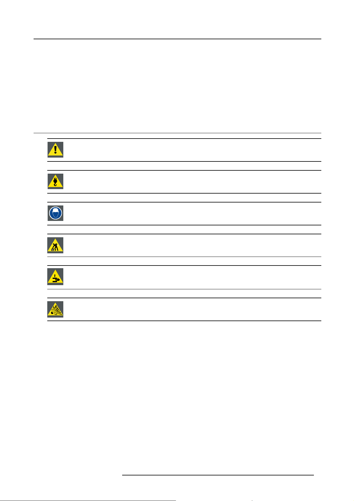
WARNING: Ensure you understand and follow all the safety guidelines, safety instructions, warnings and
cautions mentioned in this manual.
WARNING: Be aware of suspended loads.
1. Safety
WARNING: Wear a hard hat to reduce the risk of personal injury.
WARNING: Be careful while working with heavy loads.
WARNING: Mind your fingers while working with heavy loads.
CAUTION: High pressure lamp may explode if improperly handled.
General safety instructions
• Before operating this equipment please read this manual thoroughly and retain it for future reference.
• Installation and preliminary adjustments should be performed by qualified Barco personnel or by authorized Barco service deal-
ers.
• All warnings on the projector and in the documen
• All instructions for operating and use of this equipment must be followed precisely.
• All local installation codes should be adhered to.
tation manuals should be adhered to.
Notice on safety
This equipment is built in accordance with the requirements of the international safety standards IEC60950-1, EN60950-1,
UL60950-1 and CAN/CSA C22.2 No.60950-1, which are the safety standards of information technology equipment including
electrical business equipment. These safety standards impose important requirements on the use of safety critical components,
materials and insulation, in order to protect the user or operator against risk of electric shock and energy hazard and having access
to live parts. Safety standards also impose limits to the internal and external temperature rises, radiation levels, mechanical stability
and strength, enclosure construction and protection against the risk of fire. Simulated single fault condition testing ensures the
safety of the equipment to the user even when the equipment’s normal operation fails.
Users definition
Throughout this manual, the term S
necessary to be knowledgeable of potential hazards to which they are exposed (including, but not limited to HIGH VOLTAGE ELECTRIC and ELECTRONIC CIRCUITRY and HIGH BRIGHTNESS PROJECTORS) in performing a task, and of measures to minimize
R5905158 HDF W SERIES 10/07/2012 5
ERVICE PERSONNEL refers to persons having appropriate technical training and experience
Page 10

1. Safety
the potential risk to themselves or other persons. The term USER and OPERATOR refers to any person other than SERVICE PERSONNEL, AUTHORIZED to operate professional projection systems.
A HDF W series projector is intended "FOR PROFESSIONAL USE ONLY" by AUTHORIZED PERSONNEL familiar with potential
hazards associated with high voltage, high intensity light beams, ultraviolet exposure and high temperatures generated by the lamp
and associated circuits. Only qualified SERVICE PERSONNEL, knowledgeable of such risks, are allowed to perform service functions inside the product enclosure.
1.2 Important safety instructions
To prevent the risk of electrical shock
• This product should be operated from a mono phase AC power source.
• This apparatus must be grounded (earthed) via the supplied 3 conductor AC power cable. If none of the supplied power cables
are the correct one, consult your dealer.
If you are unable to insert the plug into the outlet, contact your electrician to replace your obsolete outlet. Do not defeat the
purpose of the grounding-type plug.
• Do not allow anything to rest on the power cord. Do not locate this product where persons will walk on the cord. To disconnect
the cord, pull it out by the plug. Never pull the cord itself.
• Use only the power cord supplied with your device. While appearing to be similar, other power cords have not been safety
tested at the factory and may not be used to power the device. For a replacement power cord, contact your dealer.
• Do not operate the projector with a damaged cord. Replace the cord.
Do not operate the projector if the projector has been dropped or damaged - until it has been examined and approved for
operation by a qualified service technician.
• Position the cord so that it will not be tripped over, pulled, or contact hot surfaces.
• If an extension cord is necessary, a cord with a current rating at least equ
for less amperage than the projector may overheat.
• Never push objects of any kind into this product through cabinet slots as they may touch dangerous voltage points or short out
parts that could result in a risk of fi re or electrical shock.
• Do not expose this projector to rain or moisture.
• Do not immerse or expose this projector in water or other liquids.
• Do not spill liquid of any kind on this projector.
• Should any liquid or solid object fall into the cabinet, unplug the set and have it checked by qualified service personnel before
resuming operations.
• Do not disassemble this projector, always take it to an authorized trained service person when service or repair work is required.
• Do not use an accessory attachment which is not recommended by the manufacturer.
• Lightning - For added protection for this video product during a lightning storm, or when it is left unattended and unused for long
periods of time, unplug it from the wall outlet. This will preven
t damage to the device due to lightning and AC power-line surges.
al to that of the projector should be used. A cord rated
To prevent personal injury
• Isolate electrically before replacing the lamp or lamp house. Caution: Hot lamp (house).
• Caution: High pressure lamp may explode if improperly handled. Refer servicing to qualified service personnel.
• To prevent injury and physical damage, always read this manual and all labels on the system before inserting the lamp casing,
connecting to the wall outlet or adjusting the projector.
• To prevent injury, take note of the weight of the projector. Minimum 4 persons are needed to carry the projector.
• To prevent injury, ensure that the lens and all covers are correctly installed. See installation procedures.
• Warning: high intensity light beam. NEVER look into the lens ! High luminance could result in damage to the eye.
• Warning: extremely high brightness lamps: This projector uses extr
directly into the lens or at the lamp. If the projection distance is less than 6 meter, any person needs to be at least 4 meters
away from the projected image. Avoid close range reflection of the projected image on any reflecting surface (such as glass,
metal, …) . When operating the projector, we strongly
• Before attempting to remove any of the projector’s covers, you must turn off the projector and disconnect from the wall outlet.
• When required to switch off the projector, to access parts inside, always disconnect the power cord from the power net.
• The power input at the projector side is considered as the disconnect device. When required to switch off the projector, to
access parts inside, always disconnect the power cord at the projector side. In case the power input at the projector side is not
accessible (e.g. ceiling mount), the socket outlet supplying the projector shall be installed nearby the projector and be easily
accessible, or a readily accessible general disconnect device shall be incorporated in the fixed wiring.
• Never stack more than two (2) HDF W series projectors in a hanging configuration (truss) and never stack more than three (3)
HDF W series projectors in a base stand configuration (table mount).
• When using the projector in a hanging configuration, always mount 2 safety cables. See installation manual for the correct use
of these cables.
• Do not place this equipment on an unstable cart, stand, or table. The product may fall, causing serious damage to it and
possible injury to the user.
6
recommend wearing suitable safety glasses.
emely high brightness lamps. Never attempt to look
R5905158 HDF W SERIES 10/07/2012
Page 11

1. Safety
• It is hazardous to operate without lens or shield. Lenses, shields or ultra violet screens shall be changed if they have become
visibly damaged to such an extent that their effectiveness is impaired. For example by cracks or deep scratches.
• Warning: Protection from ultraviolet radiation: Do not look directly in the light beam. The lamp contained in this product is
an intense source of light and heat. One component of the light emitted from this lamp is ultraviolet light. Potential eye and skin
hazards are present when the lamp is energized due to ultraviolet radiation. Avoid unnecessary exposure. Protect yourself and
your employees by making them aware of the hazards and how to protect themselves. Protecting the skin can be accomplished
by wearing tightly woven garments and gloves. Protecting the eyes from UV can be accomplished by wearing safety glasses
that are designed to provide UV protection. In addition to the UV, the visible light from the lamp is intense and should also be
considered when choosing protective eye wear.
• Exposure to UV radiation: Some medications are known to make individuals extra sensitive to UV radiation. The American
Conference of Governmental Industrial Hygienists (ACGIH) recommends occupational UV exposure for an-8 hour day to be
less than 0,1 micro-watts per square centimeters of effective UV radiation. An evaluation of the workplace is advised to assure
employees are not exposed to cumulative radiation levels exceeding these government guidelines. The exposer of this UV
radiation is allowed for only 1 hour per day for maintenance and service persons.
• Cooling liquid circuit. The projector contains a cooling circuit fi lled with Blue antifre
eze diluted (1/3 ethanediol – 2/3 Demi
water).
When the cooling circuit leaks, switch off the device and contact a service technician.
The liquid is not for household use. Keep out of reach of children. Harmful by oral intake. A
void exposure to pregnant women.
Avoid contact with eyes, skin and clothing. Avoid inhale of the noxious fumes.
To prevent fire hazard
• Do not place flammable or combustible materials near the projector!
• Barco large screen projection products are designed and manufactured to meet the most stringent safety regulations. This
projector radiates heat on its external surfaces and from ventilation ducts during normal operation, which is both normal and
safe. Exposing flammable or combustible materials into close proximity of this projector could result in the spontaneous ignition
of that material, resulting in a fire. For this reason, it is absolutely necessary to leave an “exclusion zone” around all external
surfaces of the projector whereby no flammable or combustible materials are present. The exclusion zone must be not less than
40 cm (16”) for all DLP projectors. The exclusion zone on the lens side must be at least 5 m. Do not cover the projector or the
lens with any material while the projector is in operation. Keep flammable and combustible materials away from the projector at
all times. Mount the projector in a well ventilated area away from sources of ignition and out of direct sun light. Never expose
the projector to rain or moisture. In the event of fire, use sand, CO
electrical fire. Always have service performed on this projector by authorized Barco service personnel. Always insist on genuine
Barco replacement parts. Never use non-Barco replacement parts as they may degrade the safety of this projector.
• Slots and openings in this equipment are provided f
or ventilation. To ensure reliable operation of the projector and to protect
it from overheating, these openings must not be blocked or covered. The openings should never be blocked by placing the
projector too close to walls, or other similar surface. This projector should never be placed near or over a radiator or heat
register. This projector should not be placed
in a built-in installation or enclosure unless proper ventilation is provided.
• Projection rooms must be well ventilated or cooled in order to avoid build up of heat.
• Let the projector cool down completely before storing. Remove cord from the projector when storing.
• Heat sensitive materials should not be placed in the path of the exhausted air or on the lamp house.
or dry powder fire extinguishers. Never use water on an
2
To prevent projector damage
• This projector has been designed for use with a specific lamp (house) type. See installation instructions for its correct type.
• The air filters of the projector must be cleaned or replaced on regular base (a "clean" booth would be monthly-minimum).
Neglecting this could result in disrupting the air flow inside the projector, causing overheating. Overheating may lead to the
projector shutting down during operation.
• The projector must always be installed in a manner which ensures free flow of air into its air inlets and unimpeded evacuation
of the hot air from its cooling system.
• In order to ensure that correct airflow is maintained, and that the projector complies with Electromagnetic Compatibility (EMC)
requirements, it should always be ope
• Slots and openings in the cabinet are provided for ventilation. To ensure reliable operation of the product and to protect it from
overheating, these openings must not be blocked or covered. The openings should never be blocked by placing the product
on a bed, sofa, rug, or other similar surface. This product should never be placed near or over a radiator or heat register. The
device should not be placed in a built-in installation or enclosure unless proper ventilation is provided.
• Ensure that nothing can be spilled on, or dropped inside the projector. If this does happen, switch off and unplug the mains
supply immediately. Do not operate the projector again until it has been checked by qualified service personnel.
• Do not block the projector cooling fans or free air movement around the projector. Loose papers or other objects may not be
nearer to the projector than 10 cm (4") on any side.
• Do not use this equipment near
• Special care for Laser Beams: Special care should be used when DLP projectors are used in the same room as high power
laser equipment. Direct or indirect hitting of a laser beam on to the lens can severely damage the Digital Mirror Devices
which case there is a loss of warranty.
• Never place the projector in direct sun light. Sun light on the lens can severely damage the Digital Mirror Devices
case there is a loss of warranty.
• Save the original shipping carton and packing material. They will come in handy if you ever have to ship your equipment. For
maximum protection, repack your set as it was originally packed at the factory.
rated with all of it’s covers in place.
water.
TM
in which
TM
in
R5905158 HDF W SERIES 10/07/2012
7
Page 12

1. Safety
• Unplug this product from the wall outlet before cleaning. Do not use liquid cleaners or aerosol cleaners. Use a damp cloth for
cleaning. Never use strong solvents, such as thinner or benzine, or abrasive cleaners, since these will damage the cabinet.
Stubborn stains may be removed with a cloth lightly dampened with mild detergent solution.
• To ensure the highest optical performance and resolution, the projection lenses are specially treated with an anti-reflective
coating, therefore, avoid touching the lens. To remove dust on the lens, use a soft dry cloth. Do not use a damp cloth, detergent
solution, or thinner.
• Rated maximum ambient temperature, t
• The lamp house shall be replaced if it has become damaged or thermally deformed.
= 40 °C (104 °F).
a
On servicing
• Do not attempt to service this product yourself, as opening or removing covers may expose you to dangerous voltage potentials
and risk of electric shock.
• Refer all servicing to qualified service personnel.
• Attempts to alter the factory-set internal controls or to change other control settings not specially discussed in this manual can
lead to permanent damage to the projector and cancellation of the warranty.
• Unplug this product from the wall outlet and refer servicing to qualified service technicians under the following conditions:
- When the power cord or plug is damaged or frayed.
- If liquid has been spilled into the equipment.
- If the product has been exposed to rain or water.
- If the product does not operate normally when the operating instructions are followed. Adjust only those controls that are
covered by the operating instructions since improper adjustment of the other controls may result in damage and will often
require extensive work by a qualified technician to restore the product to normal operation.
- If the product has been dropped or the cabinet has been damaged.
- If the product exhibits a distinct change in performance, indicating a need for service.
• Replacement parts: When replacement parts are required, be sure the service technici
parts or authorized replacement parts which have the same characteristics as the Barco original part. Unauthorized substitutions may result in degraded performance and reliability, fire, electric shock or other hazards. Unauthorized substitutions may
void warranty.
• Safety check: Upon completion of any service or repairs to this projector, ask the service technician to perform safety checks
to determine that the product is in proper operating condition.
• Possible explosion hazard: Always keep in mind the caution below:
an has used original Barco replacement
CAUTION: Xenon compact arc lamps are highly pressurized. When ignited, the normal
of the bulb increases the pressure to a level at which the bulb may explode if not handled in strict accordance
to the manufacturer’s instructions. The bulb is stable at room temperature, but may still explode if dropped or
otherwise mishandled. Whenever the lamp house, containing a xenon lamp, has t
the protective container or cloth has to be removed from the xenon lamp, authorized protective clothing MUST
be worn!
operating temperature
o be dismantled or whenever
To prevent battery explosion
• Danger of explosion if battery is incorrectly installed.
• Replace only with the same or equivalent type recommended by the manufacturer.
• For disposal of used batteries, always consult federal, state, local and provincial hazardous waste disposal rules and regulations
to ensure proper disposal.
1.3 Important warnings concerning HDF W series flight cases
Important warnings concerning stacking/transporting HDF W series rental flight cases
• Stack maximum two (2) HDF W series rental flight cases high. Never higher.
• Surface on which flight case is standing must be level to ensure that the total load is evenly spread out among the four wheels.
The surface must also be able to support the load safely.
• Before stacking or transporting flight cases, check the wheels and their fixation screws for wear or defects.
• Before stacking or transporting flight cases, check that the four lock handles on each flight case are in good working order and
locked securely.
• When stacked, make sure the wheels of the upper flight case are precisely positioned in the stacking dishes of the flight case
below.
•Stackedflight cases may not be moved. Before stacking, the lower flight case must already be in its final resting position before
placing the second upon it.
• Never stack loaded flight cases in a truck or other transport medium, unless each flight case is rigidly strapped tight.
• In the event of a wheel breaking, flight cases must be rigidly strapped tight to prevent a stack collapsing.
8
R5905158 HDF W SERIES 10/07/2012
Page 13

• Use an appropriate forklift to raise flight cases and take the necessary precautions to avoid personnel injury.
1. Safety
R5905158 HDF W SERIES 10/07/2012
9
Page 14

1. Safety
10 R5905158 HDF W SERIES 10/07/2012
Page 15
2. Configurations, requirements and restrictions
2. CONFIGURATIONS, REQUIREMENTS AND
RESTRICTIONS
About this chapter
Read this chapter before installing your HDF W series projector. It contains important information concerning installation requirements and restrictions for the HDF W series projector, such as minimum and maximum allowed ambient temperature, humidity
conditions, required safety area around the installed projector, required power net, tilt, e
Furthermore, careful consideration of things such as image size, ambient light level, projector placement and type of screen to use
are critical to the optimum use of the projection system.
Overview
• Installation requirements
• Unpacking the projector
• HDF W series flight case
• Projector configurations
• Projector air inlets and outlets
• Free download of Projector Toolset
• Installation process overview
tc.
2.1 Installation requirements
Environment conditions
Table below summarizes the physical environment in which the HDF W series p
Environment
Ambient Temperature
Humidity
Altitude
Let the projector acclimatize after unpacking. Neglecting this may result in a startup failure of the Light Processor Unit.
Operating Non-Operating
10 °C (50 °F) to 40 °C (104 °F) -15°C (5°F) to 60°C (140°F)
5% to 85% RH Non-condensed 5% to 95% RH Non-Condensed
-60 (-197Ft) to 3000m (9843Ft) -60 (-197Ft) to 10000m (32810Ft)
Cooling requirements
The projector is fan cooled and must be installed with sufficient space around the projector head, minimum 10 cm (4 inch) to ensure
sufficient air flow. It should be used in an area where the ambient temperature, as measured at the projector air inlet , does not
exceed +40 °C (104 °F).
Clean air environment
A projector must always be mounted in a manner which ensures the free flow of clean air into the projectors ventilation inlets. For
installations in environments where the projector is subject to airborne contaminants such as that produced by smoke machines or
similar (these deposit a thin layer of greasy residue upon the projectors internal optics and imaging electronic surfaces, degrading
performance), then it is highly advisable and desirable to have this contamination removed prior to it reaching the projectors clean
air supply. Devices or structures to extract or shield contaminated air well away from the projector are a prerequisite, if this is not a
feasible solution then measures to relocate the projector to a clean air environment should be considered.
Only ever use the manufacturer’s recom
use industrial strength cleaners on the projector’s optics as these will degrade optical coatings and damage sensitive optoelectronics
components. Failure to take suitable precautions to protect the projector from the effects of persistent and prolonged air contaminants will culminate in extensive
be noneffective and impracticable. Damage of this nature is under no circumstances covered under the manufacturer’s warranty
and may deem the warranty null and void. In such a case the client shall be held solely responsible for all costs incurred during any
repair. It is the clients respons
particles in the environment of the projector. The manufacturer reserves the right to refuse repair if a projector has been subject to
knowingly neglect, abandon or improper use.
ibility to ensure at all times that the projector is protected from the harmful effects of hostile airborne
mended cleaning kit which has been specifically designed for cleaning optical parts, never
and irreversible ingrained optical damage. At this stage cleaning of the internal optical units will
rojector may be safely operated or stored.
Main Power requirements
The HDF W series projector operates from a nominal mono phase power net with a separate earth ground PE.
R5905158 HDF W SERIES 10/07/2012
11
Page 16
2. Configurations, requirements and restrictions
Projector Power requirements
HDF W22
HDF W26 200-240 VAC, 50-60Hz, 24A at 200 VAC
The power cord required to connect the projector with the power net is delivered with the projector.
200-240VAC, 50-60Hz, 24A at 200 VAC
Projector weight
Do not underestimate the weight of the HDF W series projector. The projector weights about ±100 kg (±225 lb.) without lens. Be
sure that the pedestal on which the projector has to be installed is capable of handling five (5) times the complete load of the system.
2.2 Unpacking the projector
What has to be done ?
At delivery the projector is packed in a carton box upon a wooden pallet and secured with banding and fastening clips. Furthermore,
to provide protection during transportation, the projector is surrounded with foam. Once the projector is arrived at the installation
site, it has to be removed from the carton box and wooden pallet in a safe manner without damaging the projector.
Necessary tools
• Side cutter.
• 8 mm Allen key.
How to unpack the projector ?
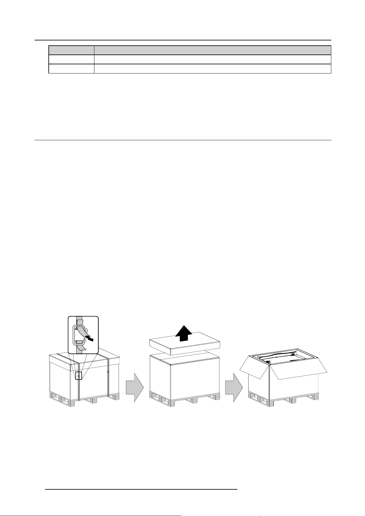
1. Remove the banding around the carton box, by releasing the fastening clips as illustrated, and remove the top cover. (image 2-1)
2. Remove the power cord, which is attached to the packaging with a cable ties, and the two smaller carton boxes, located between
the inner carton sleeve and outer carton box. (image 2-2)
Note: The two smaller carton boxes contain the manuals, the remote control unit (RCU), two standard batteries size AA and
four rigging clamps for projector suspension.
3. Remove the carton box, the inner carton sleeve and the foam around the projector. See image 2-2.
Note: The projector is still attached to a wooden plate, which is detached from the below pallet.
4. Gently turn the projector upside down to gain access to the four bolts, whic
detached from the pallet. (image 2-3)
Tip: Lay a blanket (or the earlier remove d foam) on the fl oor to protect the projector housing form scratches while turning.
5. Remove the wooden plate from the projector bottom, by releasing the four bolts. Use an 8 mm Allen key. See image 2-3.
6. Gently turn the projector back on its feet.
7. Remove the foam rubber around the carrying handle.
h secure the projector. Note that this wooden plate is
Image 2-1
12 R5905158 HDF W SERIES 10/07/2012
Page 17
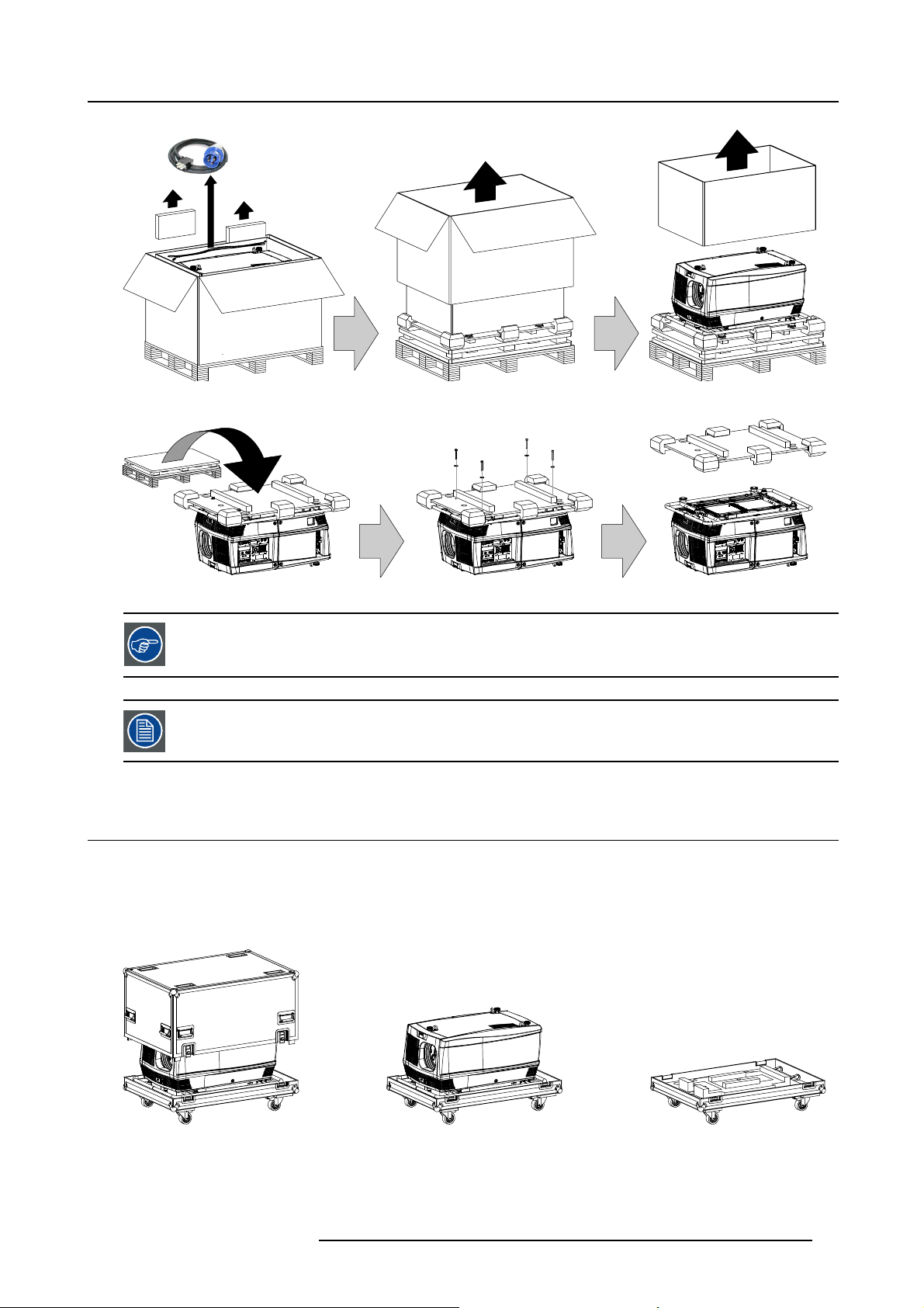
Image 2-2
2. Configurations, requirements and restrictions
Image 2-3
Save the original shipping carton and packing material, they will
projector. For maximum protection, repack your projector as it was originally packed at the factory.
A rubber foam inside a plastic bag is placed into the lens opening of the projector. It’s recommended to reuse
this foam and plastic back each time you transport the projector. This to prevent intrusion of dust and foreign
particles.
be necessary if you ever have to ship your
2.3 HDF W series flight case
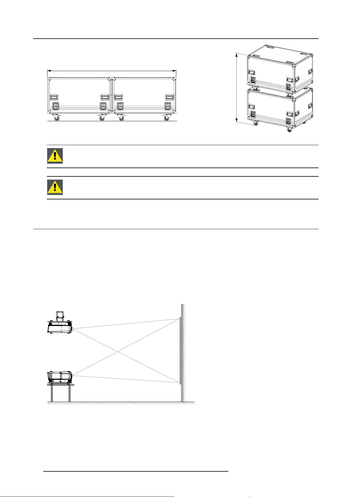
Introduction of the HDF W series flight case
The HDF W series flight case is designed to transport the HDF W series projector in a safe and secure manner. The four caster
wheels, provided with breaks, and the eight handles make the HDF W series flight case easy to handle. The floor of the flight case
wagon is equipped with two small covered compartments to store the remote control and the rigging clamps. Furthermore, three
Velcro strips are attached to the bottom for fastening the power cord of the projector.
Image 2-4
HDF W series flight case (R9854510).
The dimensions of the HDF W series flight case are optimal for maximum utilization of the floor area of a truck. The cover of the
HDF W series flight case has four stacking dishes, which allows to stack the flight cases.
R5905158 HDF W SERIES 10/07/2012
13
Page 18
2. Configurations, requirements and restrictions
2400 mm
Image 2-5
WARNING: Maximum stack two (2) HDF W series flight cases high. Never higher.
CAUTION: Prior to inserting projector in flight case turn in the adjustable feet and interlocking adapters fully.
m
m
0
0
6
1
2.4 Projector configurations
The different configurations
Depending on the installation the projector can be mounted in different ways, the 4 different configurations are:
1. Front / Table (F/T)
2. Front / Ceiling (F/C)
3. Rear / Table (R/T)
4. Rear / Ceiling (R/C)
Front projection
The projector is installed, either in a table mount or ceiling mount configuration, at the same side of the screen as the audience.
AUDIENCE
F/C
F/T
SCREEN
FLOOR
Image 2-6
Front projection
Rear projection
The projector is installed, either in a table mount or ceiling mount configuration, at the other side of the screen opposite the audience.
14
R5905158 HDF W SERIES 10/07/2012
Page 19
AUDIENCE BACKSTAGE
Image 2-7
Rear projection
Positioning the projector
FLOOR
2. Configurations, requirements and restrictions
N
E
E
R
C
S
SW
R/C
R/T
PD
SCREENSCREEN
SHB
SHB
A
SCREEN
CD
FLOOR
CD
SW
Image 2-8
Projector positioning
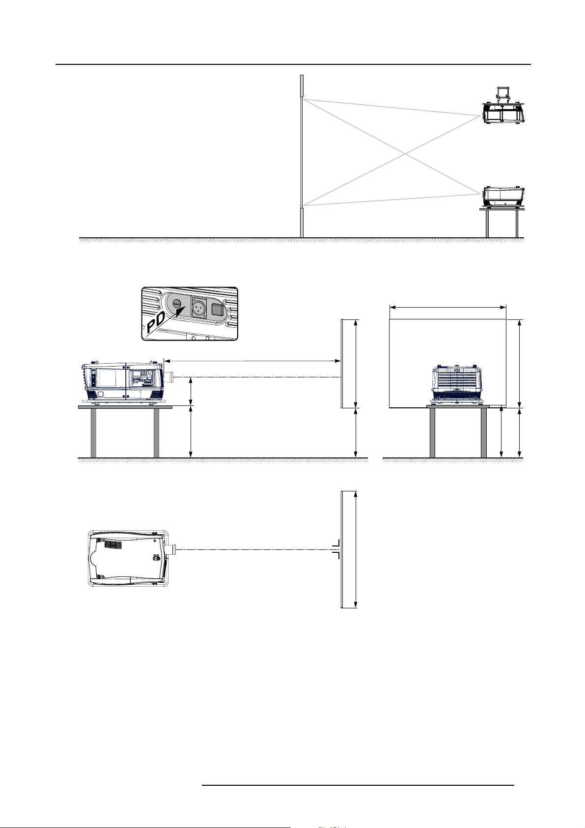
The projector should be installed at right angles (horizontally and vertically) to the screen at a distance PD. Note the distance (A)
between lens centre and table surface is slightly variable. This distance (A) is nominal 35 cm in case all feet are turned in completely
and the vertical lens shift is set to zero (0).
On-Axis / Off-Axis projection
The position of the projector with reference to the screen may also be different depending on the installation. Basically the projector
can be positioned in On-Axis or Off-Axis configuration. On-Axis configuration means that the projector is positioned so as to have
the centre of the lens coinciding with the centre of the screen. Off-Axis projection is obtained by shifting the lens up, down, left or
right. Several parameters can be calculated determining the position in any installation.
Formula to calcul
R5905158 HDF W SERIES 10/07/2012
ate the distance CD for On-Axis projection: CD=SH/2+B-A
15
Page 20
2. Configurations, requirements and restrictions
Shift range
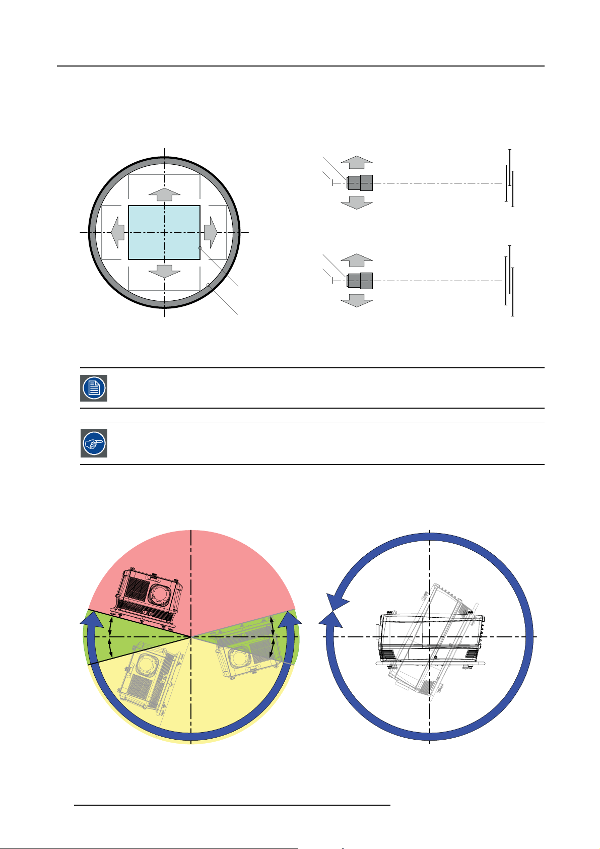
The lens can be shifted with respect to the DMD (P) which result in a shifted image on the screen (Off-Axis). A 100% shift means that
the centre point of the projected image is shifted by half the screen size. In other words, the centre point of the projected image falls
together with the outline of the image in an On-Axis projection. Due to mechanical and optical limitations it’s recommended to keep
the shift values within the field of view (F) as illustrated below. Within these shift ranges the projector and lens perform excellently.
Configuring the projector outside these shift ranges will result in a slight decline of image quality.
U
-50% +50%
L R
D
Image 2-9
Vertical and horizontal shift range
PDMD.
F Field of vi ew.
It is mechanical possible to shift outside the recommended field of view, but it will result in a decline of image
quality depending on the used lens and the zoom position of the used lens. Furthermore, shifting too much
in both directions will result in a blurred image corner.
Best image quality is projected in the On-Axis configuration.
+120%
-20%
F
P
F
P
P
F
U
D
L
R
SIDE VIEW
TOP VIEW
+120%
-20%
-50%
+50%
Horizontal and vertical projector tilt ranges
The projector can be rotated and mounted at any vertical angle. In other words, you can tilt the lens side of the projector as much
as desired for your application. Side t
operates properly and safely. More tilting within area C is allowed but lamp flicker can happen.
o side tile, however, must not exceed ±15°. This limit ensures that the lamp in the projector
B
MAX
15°
15°
A
A
15°
15°
MAX
360°
C
Image 2-10
A Tilting allowed without problems
B No tilting allo wed in th is area
C Tilting a llowed but l amp flicker possible
16 R5905158 HDF W SERIES 10/07/2012
Page 21
Projector lamp will not start up when out of tilt range due to build-in tilt sensor.
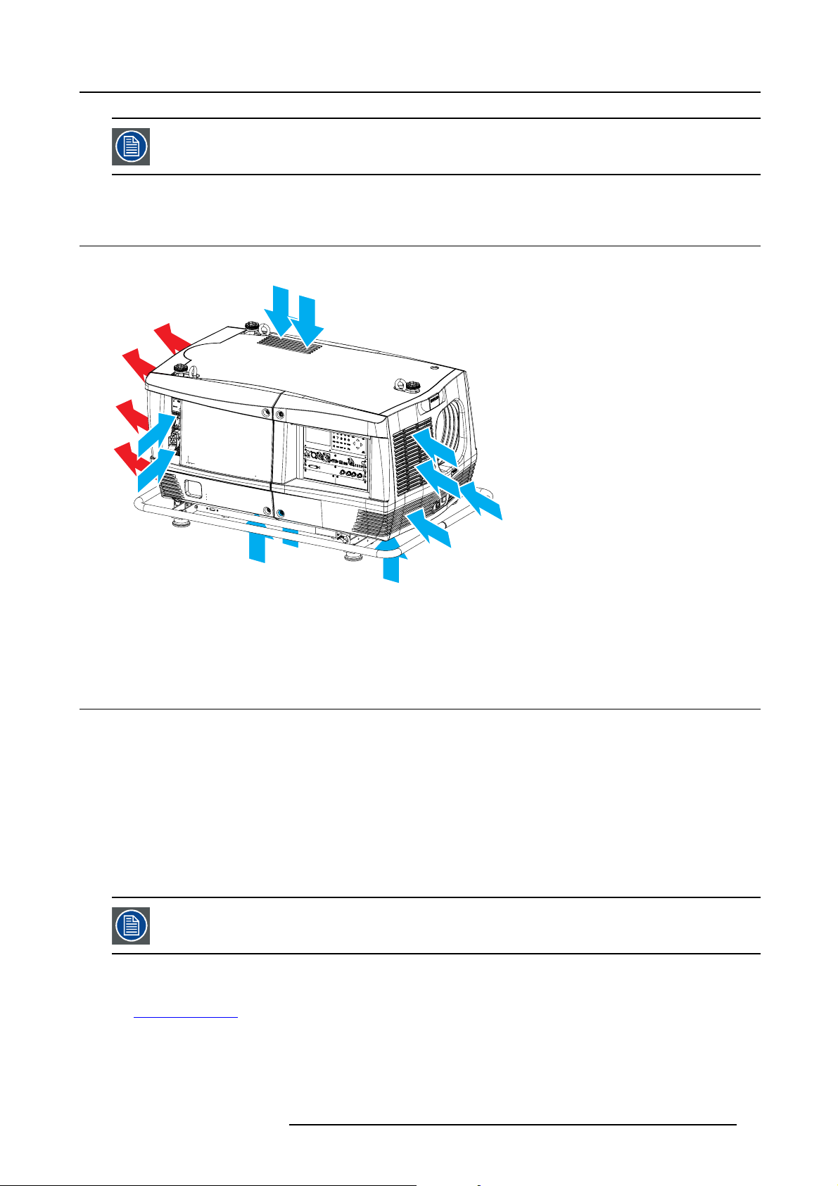
2.5 Projector air inlets and outlets
Air inlets and outlets
2. Configurations, requirements and restrictions
Image 2-11
Airflow
The HDF W series has 5 air inlet channels and one air outl
located at the front, bottom, top and right side of the projector.
et. The air outlet is located at the rear of the projector. The air inlets are
2.6 Free download of Projector Toolset
About Projector Toolset
Projector Toolset is a software tool to set up, configure, manage and control Barco projectors.
The concept of this Projector Toolset software is modular. The basic package can be extended with several optional device plug-in
modules, now and in the future available.
The Projector Toolset software works with configurations that can be loaded. Within a configuration, different snapshots can be
taken. A snapshot represents a current state of a configuration and can be reloaded to return to this typical state. These terms will
be used through the complete software.
Projector Toolset is a stand-alone application that runs on a Java Virtual Machine and that does not require extra services to run.
Several configurations can be controlled simultaneously. Even when the configurations are connected via different ways.
Projector Toolset is only available in a download version, no CD can be ordered.
Where to find the download file(s
The program and all necessary plug-ins, as well as the Reference manual can be downloaded for free from Barco’s Partnerzone,
URLh
ttps:\\my.barco.com. Registration is necessary.
If you are not yet registered, click on Partnerzone registration and follow the instructions. With the created login and password, it is
possible to enter the partnerzone where you can download the Projector Toolset software and the device plug-in updates as well as
the corresponding reference manual.
)
R5905158 HDF W SERIES 10/07/2012
17
Page 22
2. Configurations, requirements and restrictions
When downloading the complete Projector Toolset, this software contains already the latest device plug-ins. When you already have
the latest core version of Projector Toolset, it is possible to download only device plug-in updates from the same web site location.
As Projector Toolset is a stand alone application, it is not necessary to install any other software. A Java virtual machine is included
with this download.
Installation
Download first the reference manual (Part number: R59770052) and follow the installation instructions as written in this manual.
2.7 Installation process overview
Quick setup
The following steps describe briefly how to setup your HDF W series projector in a table mount front projection. Note that each step
refers to a corresponding procedure, which is more detailed and illustrated.
1. Install the batteries of the remote control. See "RCU battery installation", page 19
2. Place the projector on a solid table in front of the screen at the expected throw distance. Ensure that t
right angles (horizontally and vertically) with the screen. See "Projector configurations", page 14.
3. Select and install an appropriate lens, which covers the throw ratio ( = screen size / projector screen distance). See "Lenses",
page 23.
4. Connect the projector with the local power net. See "Power connection", page 33.
5. Connect your source to the appropriate input module. See "Input source connections", page 40.
6. Switch ON the projector. See "Power on projector", page 47.
7. Select the input slot to which the source is connected. Do this by pressing the numeric key on the remote control unit or on the
local keypad, See "Source selection", page 53.
8. Zoom and shift the lens until the image is properly projected on the screen, Do this by using the “ZOOM” and “FOCUS” key on
the remote control unit or on the local keypad. If necessary, level the projector from side to side by turning the adjustable feet in
or out.
he projector is installed at
Check cooling liquid level at least every 6 months.
Every 6 months at device power up a message will be displayed on the local LCD to check the cooling liquid
level
18 R5905158 HDF W SERIES 10/07/2012
Page 23
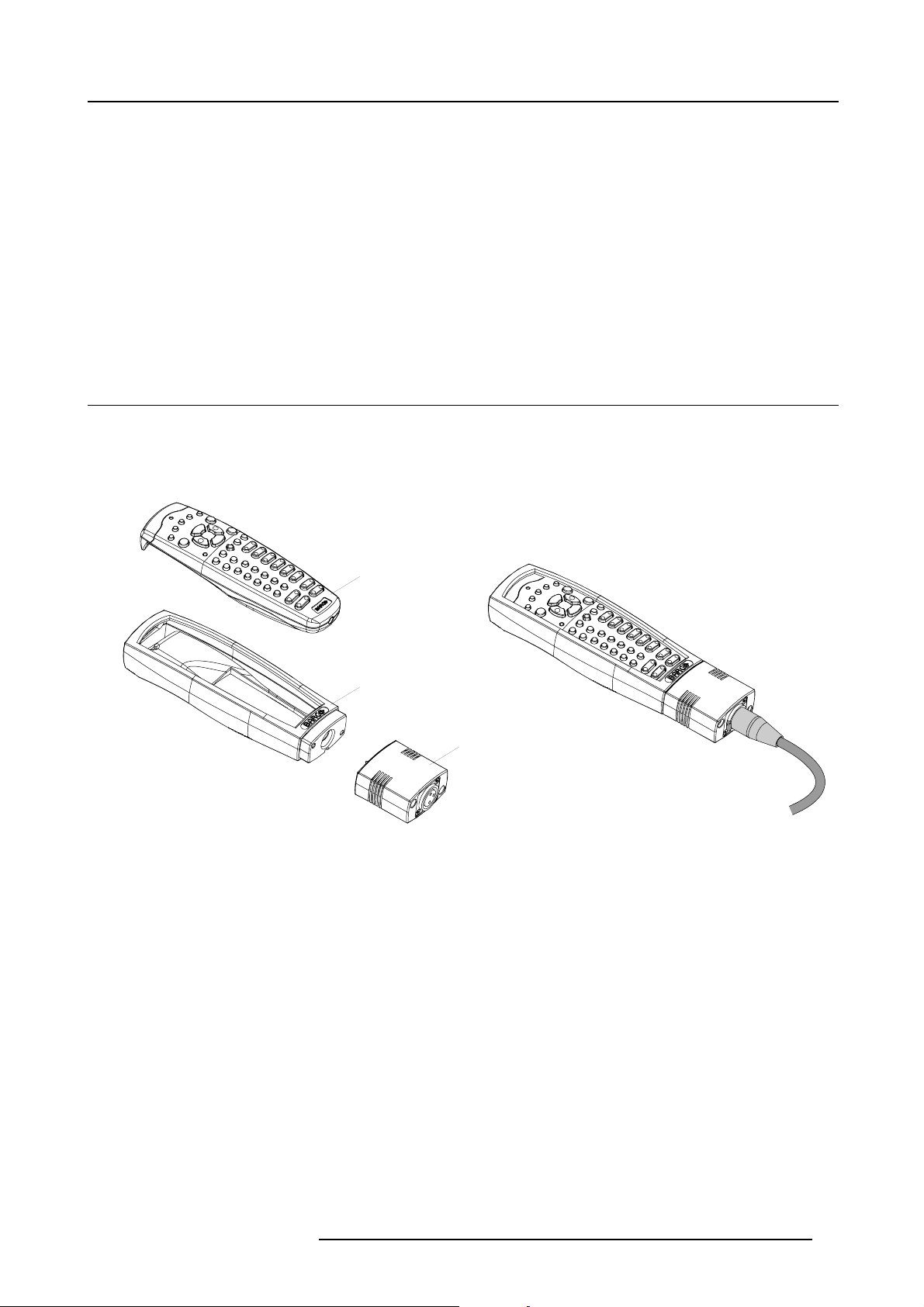
3. Physical installation
3. PHYSICAL INSTALLATION
About this projector
This chapter describes how the mechanical set up of the projector has to be done and how to realize the electrical connections.
Overview
• Remote control unit (RCU)
• Lenses
• Power connection
• Suspension of the HDF W series projector with rigging clamps
3.1 Remote control unit (RCU)
Introduction
The remote control unit (A) of the HDF W series projector is equipped with a rugged case (B) and an XLR adaptor (C). The remote
control unit can be used wired via mini-jack or via rugged XLR. Note that the backlight, of the remote control unit, illuminate continuously when wire connected.
Image 3-1
A Remote control unit (RCU).
B Rugged case.
C XLR adaptor.
Overview
• RCU battery installation
• RCU rugged case installation
• RCU XLR adaptor installation
• Using the XLR adaptor of the RCU
• RCU usage possibilities
A
B
C
3.1.1 RCU battery installation
Where to find the batteries for the remote control ?
The batteries are not placed in the remote control unit to avoid control operation in its package, resulting in a shorter battery life
time. At delivery the batteries c
install the batteries first.
an be found in a separated bag attached to the remote control unit. Before using your remote control,
How to install the batteries in the remote control ?
1. Push the battery cover tab with the fingernail a little backwards (1) and pull, at the same time, the cover upwards (2). (image 3-2)
2. Insert the two AA size batteries, making sure the polarities match the + and - marks inside the battery compartment. (image 3-3)
R5905158 HDF W SERIES 10/07/2012
19
Page 24
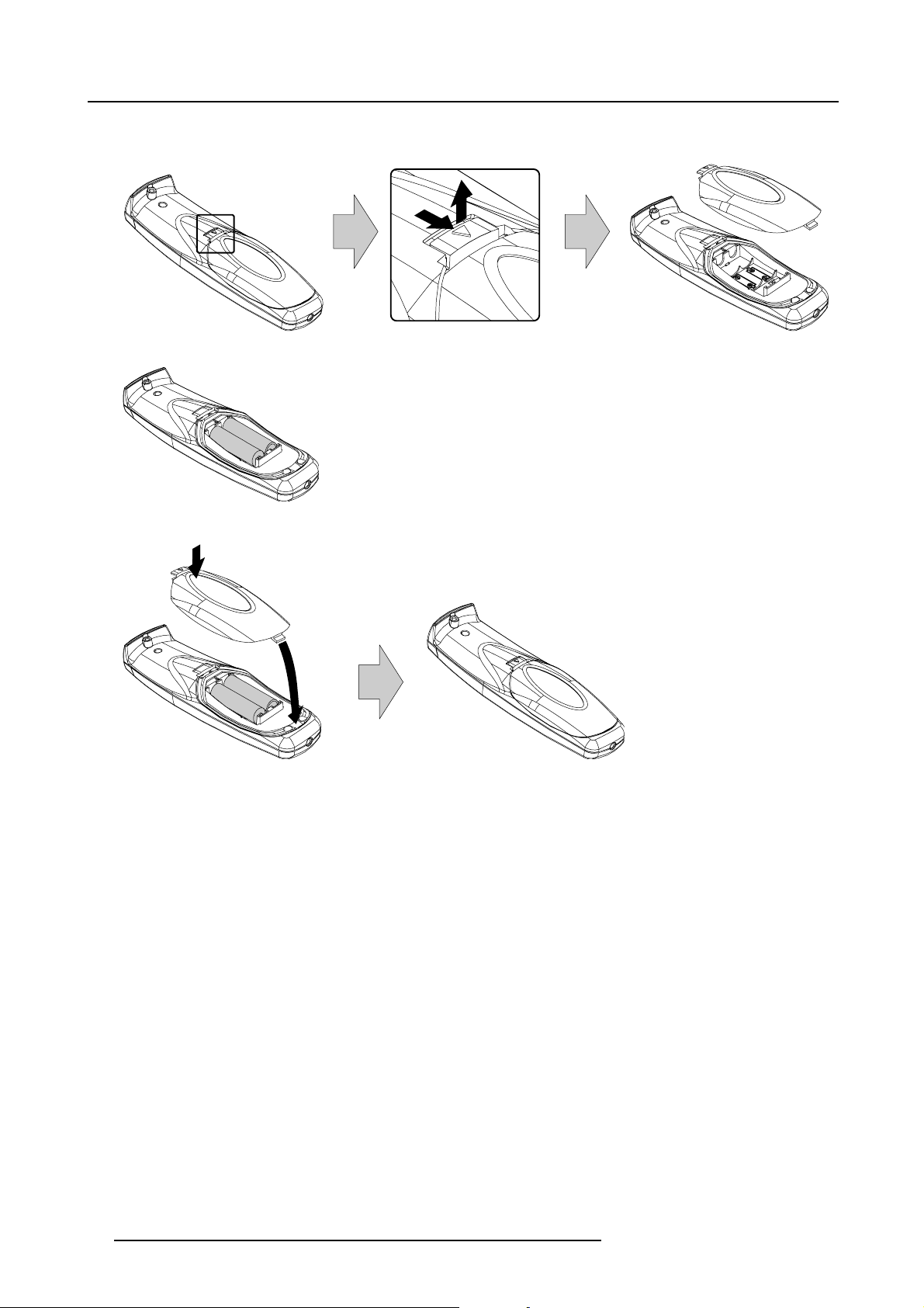
3. Physical installation
3. Insert (1) the lower tab of the battery cover in the gap at the bottom of the remote control, and press (2) the cover until it clicks
in place. (image 3-4)
Image 3-2
Image 3-3
1
+
+
-
2
2
+
-
+
Image 3-4
To prevent battery explosion
• Danger of explosion if battery is incorrectly installed.
• Replace only with the same or equivalent type recommended by the manufacturer.
• Disposal of used batteries must be done according to the manufacturer’s instruction.
3.1.2 RCU rugged case installation
How to install the rugged case of the remote control ?
1. Slide the bottom of the RCU into the rugged case and then pull the top of the rugged case over the top of the RCU as illustrated.
(image 3-5)
1
-
20
R5905158 HDF W SERIES 10/07/2012
Page 25
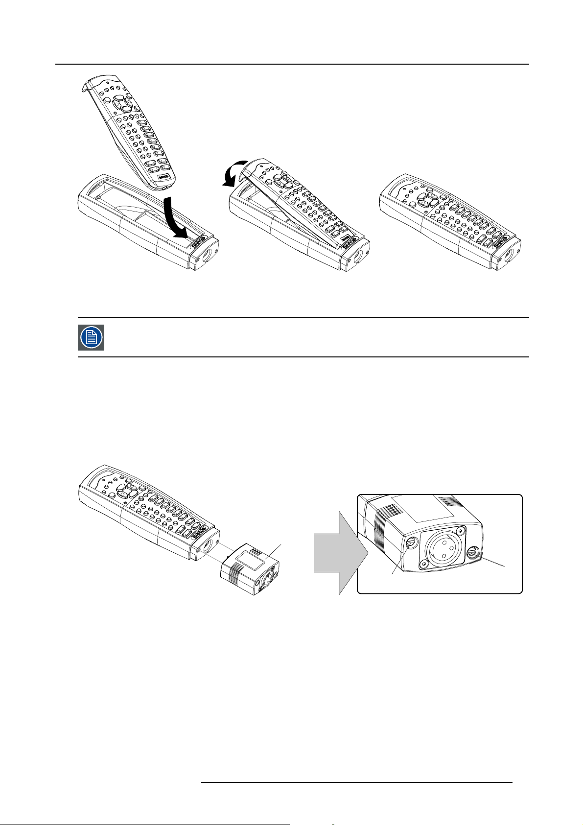
Image 3-5
3.1.3 RCU XLR adaptor installation
Install the rugged case before installing the XLR adaptor. Vice-versa, remove the XLR adaptor before removing
the rugged case from the RCU.
3. Physical installation
Necessary tools
5mmflat screw driver.
How to install the XLR adaptor of the remote control unit ?
1. Push the XLR adaptor (C) upon the rugged case of the remote control unit as illustrated. (image 3-6)
Note: Ensure that the text of the XLR adaptor is on top.
2. Fasten the two screws (S) of the XLR adaptor. Turn each screw repeatedly one or two turns until both screws are tight.
C
S
Image 3-6
3.1.4 Using the XLR adaptor of the RCU
How to use the XLR adaptor of the remote control unit ?
1. Connect a cable with XLR plug into the XLR adaptor.
2. Connect the other end of the cable with your HDF W series projector.
3. Push the XLR adaptor completely against the rugged case of the remote control unit, as illustrated in the left image below, for
wired communication. Pull out th
e XLR adaptor (about 8 mm) to switch over to wireless communication. (image 3-7)
S
R5905158 HDF W SERIES 10/07/2012
21
Page 26
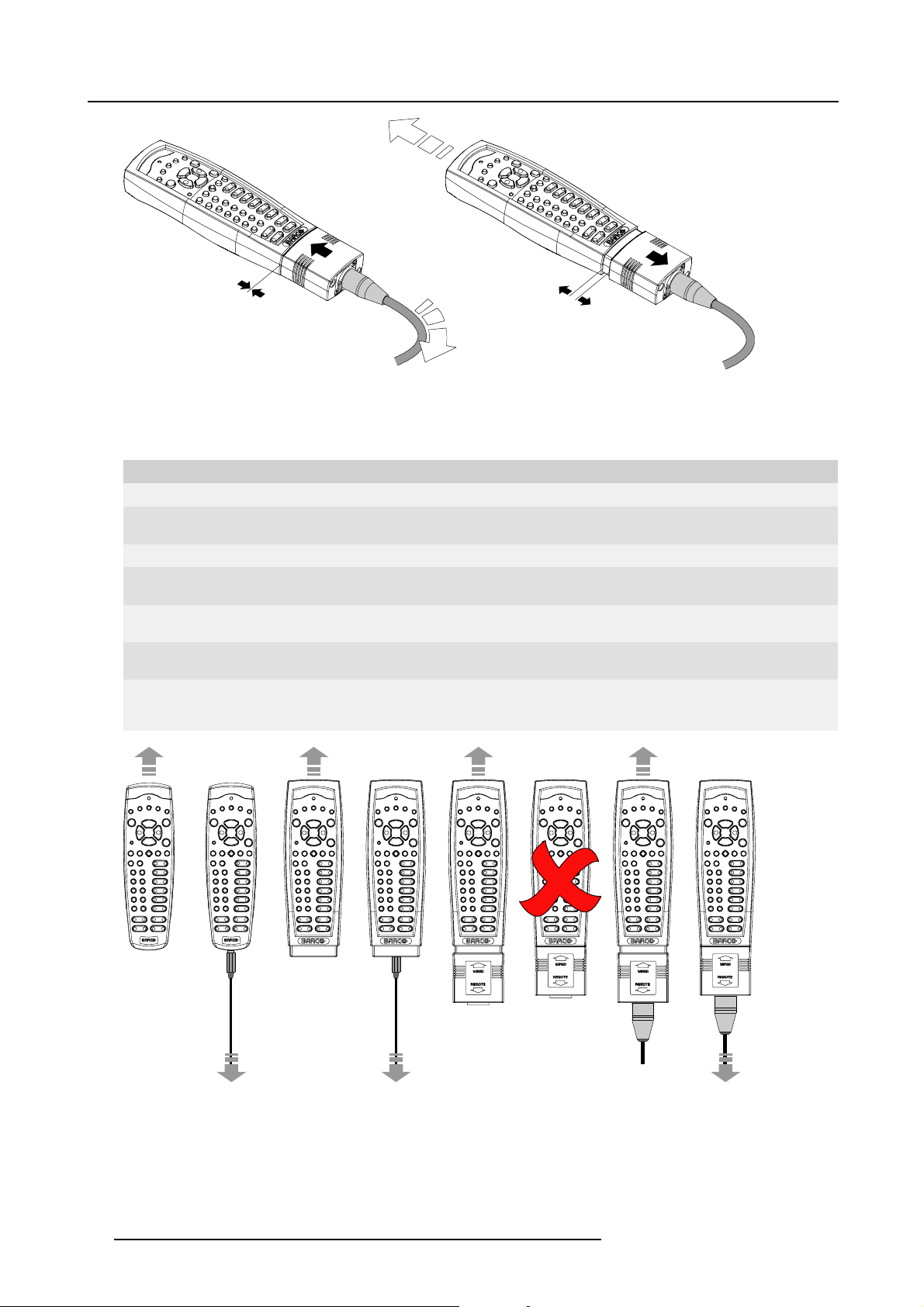
3. Physical installation
Image 3-7
3.1.5 RCU usage possibilities
Summarized possibilities
Ref. Possibility description Comment
a.
RCU not wired
b. RCU wired (mini-jack) Backlight illuminates continuously when wire is connected. Infra red
c.
RCU with rugged case not wired
d.
RCU with rugged case wired (mini-jack) Backlight illuminates continuously when wire is connected. Infra red
e.
RCU with rugged case and XLR adaptor
pulled out “REMOTE” and not wired
f. RCU with rugged case and XLR adaptor
pulled out “REMOTE” and wired
g.
RCU with rugged case and XLR adaptor
pushed in “WIRED” and wired
disabled.
disabled.
The XLR adaptor must be in the pulled out position “REMOTE”, otherwise
the RCU will not function.
The RCU will send the commands via infra red to the projector.
The RCU will send the commands via the cable connected with the XLR
adaptor to the projector. Backlight illuminates continuously when wire
is connected. Infra red disabled.
abcd fge
Image 3-8
22 R5905158 HDF W SERIES 10/07/2012
Page 27
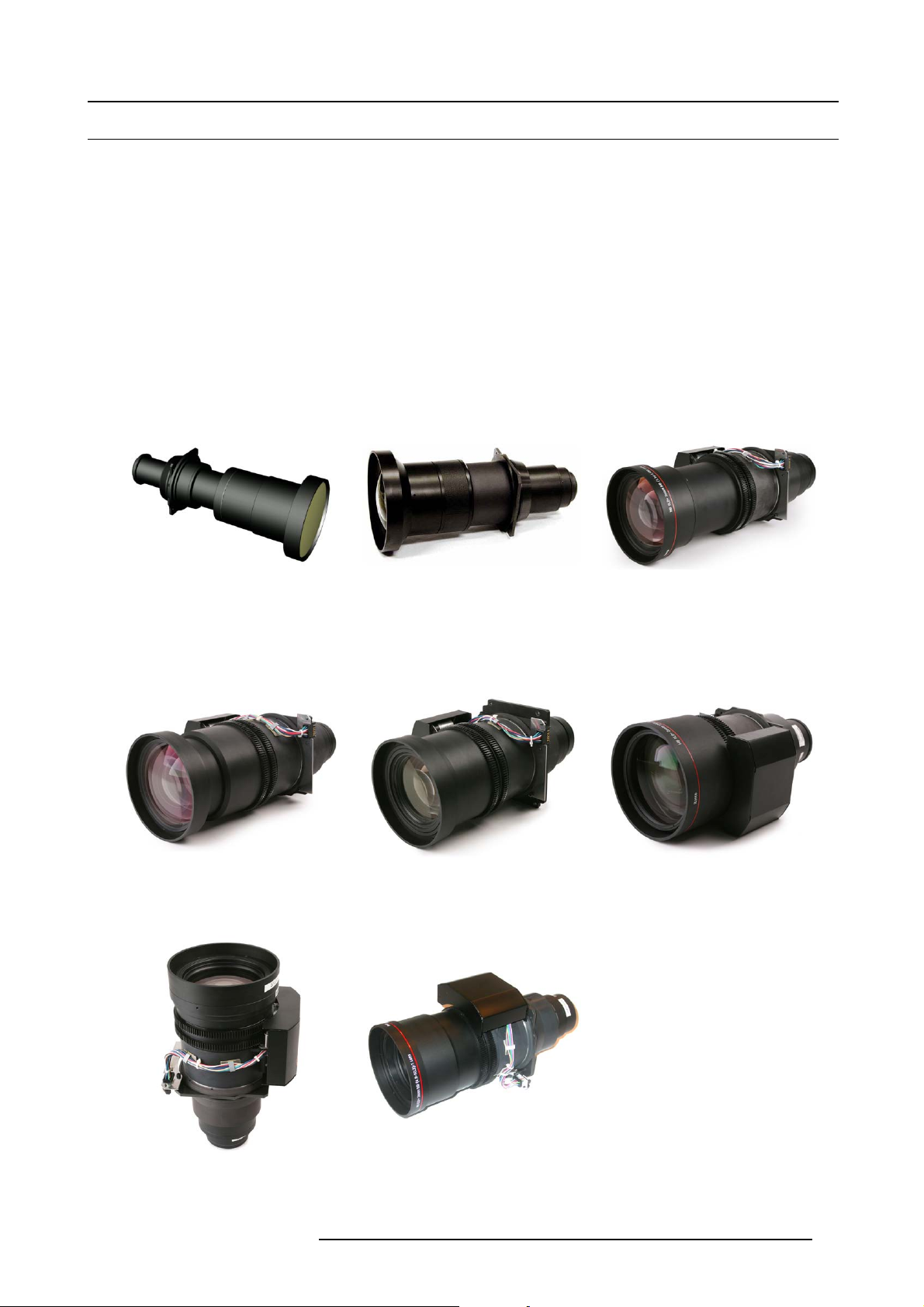
3.2 Lenses
Overview
• Available lenses
• Lens selection
• Lens installation
• Lens removal
• Lens safety cable (optional)
• Lens shift, zoom & focus
• Scheimpflug adjustment
3.2.1 Available lenses
Available lenses for the HDF W series projector
3. Physical installation
Image 3-9
R9840775: TLD+ (1.16 : 1) fixed lens
Image 3-12
R9862010: TLD+ zoom lens (1.39 - 1.87 : 1)
Image 3-10
R9862000: TLD+ lens (0.67 : 1)
Image 3-13
R9862020: TLD+ zoom lens (1.87 - 2.56 : 1)
Image 3-11
R9862005: TLD+ zoom lens (1.16 - 1.49 : 1)
Image 3-14
R9862030: TLD+ zoom lens (2.56 - 4.16 : 1)
Image 3-15
R9862040: T LD+ zoom lens (4.1 6 - 9.6 : 1)
Image 3-16
R9829997: TLD+ zoom lens (9.6 - 10.39 : 1)
R5905158 HDF W SERIES 10/07/2012 23
Page 28
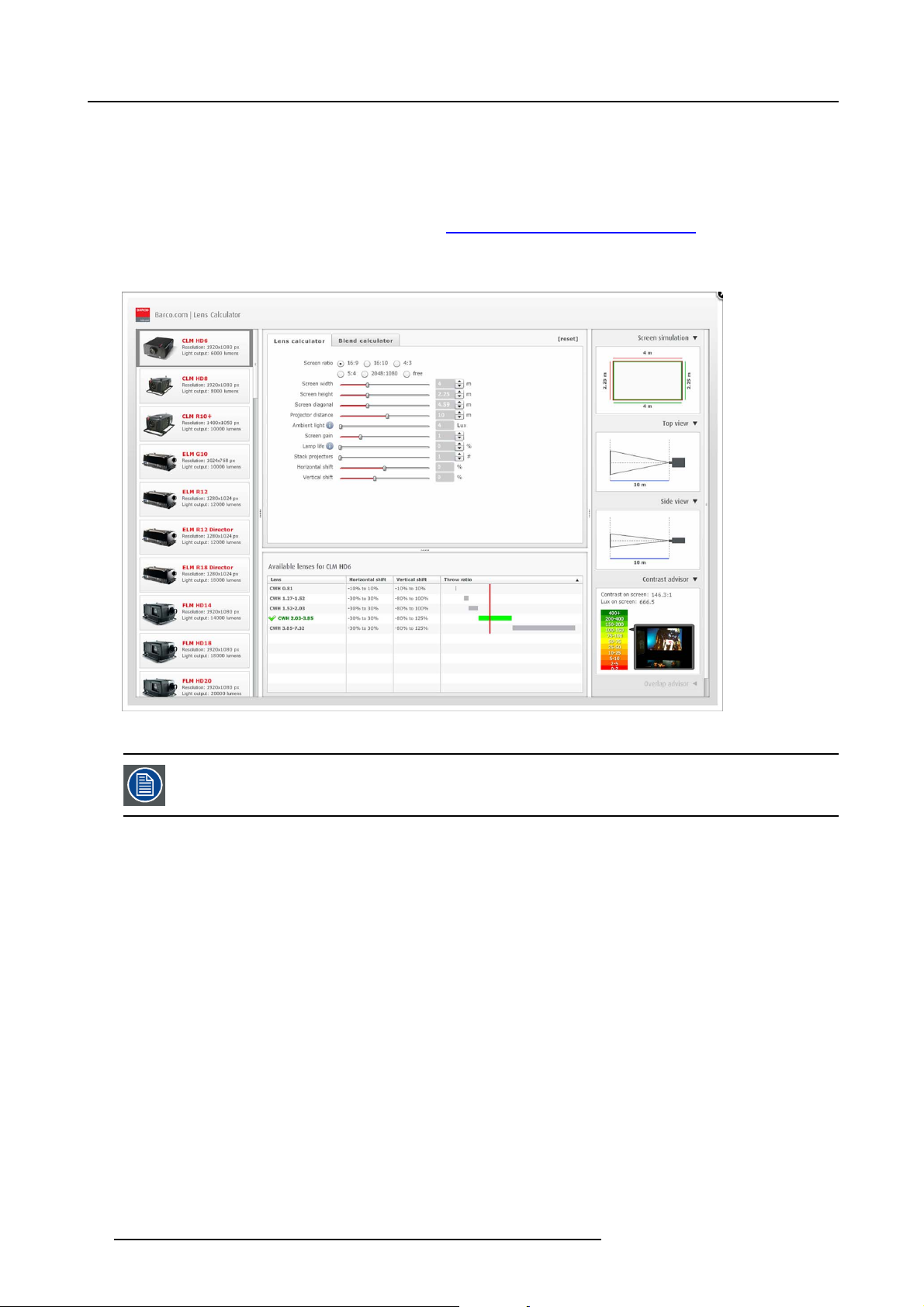
3. Physical installation
3.2.2 Lens selection
How to select the right lens
1. Determine the required screen width (SW).
2. Determine the approximate position of the projector in the room.
3. Start up the Lens Calculator ontheBarcowebside: h
lenses for your confi guration.
The Lens Calculator window opens. (image 3-17)
ttp://www.barco.com/en/tools/lenscalculator to determine the possible
Image 3-17
Lens calculator
The Lens Calculator can also be used to determine the position of the projector when the lens type and screen
width is known.
3.2.3 Lens installation
How to install
1. Remove the foam rubber in the opening of the lens holder if not removed yet.
2. Take the lens assembly out of its packing mat
3. Place the lens holder in the “unlocked” position by moving the lens lock handle (A) towards the lens power supply socket (B) as
illustrated. (image 3-18)
4. Ensure that the lens holder stands in the On-Axis position (horizontal and vertical mid position).
Note: The lens holder is placed default in the O n-Axis position at factory.
5. Gently insert the lens in such a way that the lens connector matches the socket (B). (image 3-19)
6. Insert the lens until the connector seats into the socket.
Warning: Do not release the Lens yet, as the Lens m ay fall out of the Lens Holder.
7. Secure the lens in the lens holder by sliding the lens lock handle into the “locked” position, which is away from the lens power
supply socket. Ensure the lens touches the front plate of the lens holder. (image 3-20)
8. Check if the lens is really secured by trying to pull the lens out of the lens holder.
erial and remove the lens caps on both sides.
24
R5905158 HDF W SERIES 10/07/2012
Page 29
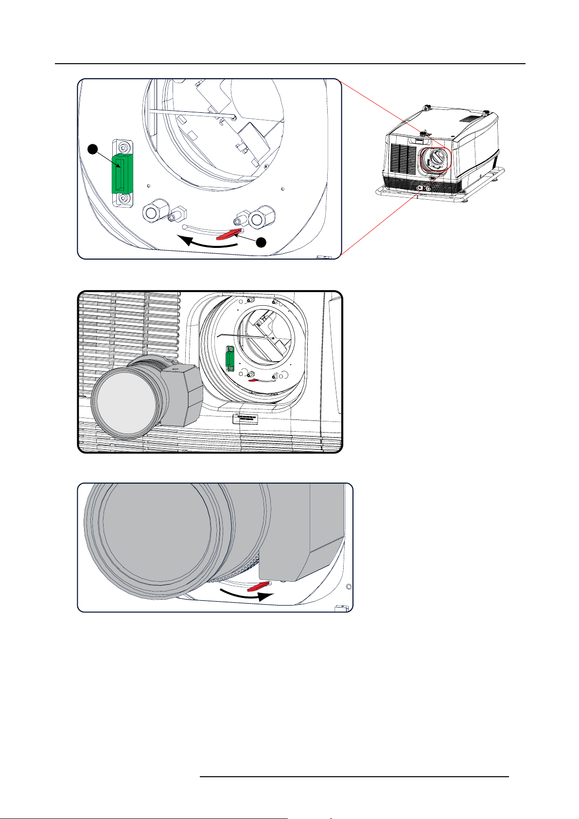
B
Image 3-18
Lens installation, preparation
3. Physical installation
A
Image 3-19
Lens insertion
Image 3-20
Lock lens
3.2.4 Lens removal
How to remove
1. Support the lens with one hand while you unlock the lens holder by sliding the lock handle towards the “unlocked” position as
illustrated. (image 3-21)
2. Gently pull the lens out of the lens holder. (image 3-22)
R5905158 HDF W SERIES 10/07/2012
25
Page 30
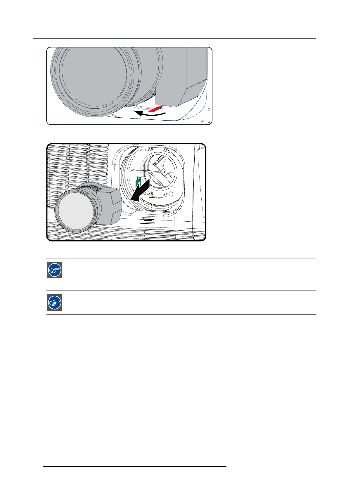
3. Physical installation
Image 3-21
Lens removal, unlock
Image 3-22
Lens removal
It’s recommended to place the Lens caps of the original Lens packaging, back on both sides of the removed
Lens to protect the optics of the Lens.
It’s recommended to place the foam rubber of the original projector packaging, back in the Lens opening to
prevent intrusion of dust. Note that this foam rubber is packed in a plastic bag to prevent the dust, emitted by
the foam, from entering the projector.
3.2.5 Lens safety cable (optional)
When using the safety cable ?
The lens safety cable can be used in any circumst
ances to protect a mounted lens in the lens holder.
How to mount the cable
1. Put the safety cable around the lens. Make sure the cable is mounted between the motor part and the mounting flange (image 3-23)
2. Insert both cable sides into the clamp;
Strap the cable and make sure that the clamp is positioned on 45° from the bottom to avoid interference of the cable with the
lens locking mechanism.
Secure the cable by fixating the nut of the clamp. (image 3-24)
3. Turn the cable with hook lock around the carry handle and hook the hook lock around the cable. (image 3-25)
26
R5905158 HDF W SERIES 10/07/2012
Page 31

3. Physical installation
2
1
3
3
Image 3-23
Lens safety cable
1 Lens motor block
2 Mounting flange
3Clamp
Image 3-24
Clamp position
R5905158 HDF W SERIES 10/07/2012 27
Page 32

3. Physical installation
Image 3-25
3.2.6 Lens shift, zoom & focus
Via Lens key
1. Press LENS key on the local keypad or the remote control.
The zoom/focus menu opens. (image 3-26)
2. Use the ▲ or ▼ key to zoom the lens.
Use the ◄ or ► key to focus the lens.
Press ENTER to switch to Lens shift adjustment. (image 3-27)
3. Use the ▲ or ▼ key to shift the lens in vertical direction.
Use the ◄ or ► key to shift the lens in horizontal direction.
Press ENTER to switch to zoom/focus adjustment.
Image 3-26
Zoom/Focus adjustment
28 R5905158 HDF W SERIES 10/07/2012
Page 33

Image 3-27
Shift adjustment
Via direct access keys on the remote control
1. Press LENS FOCUS button [-] or [+] (C) for an overall focus of the image.
2. Press ▲ LENS SHIFT ▼ button for correct vertical position of the image on the screen.
3. Press ◄ LENS SHIFT ► button for correct horizontal position of the image on the screen.
3. Physical installation
3.2.7 Scheimpflug adjustment
What has to be done ?
The lens holder has to be adjusted so that the “sharp focus plane” of the projected image falls together with the plane of the screen
(Fp1→Fp2). This is achieved by changing the distance between the DMD plane and the lens plane (Lp1→Lp2). The closer the lens
plane comes to the DMD plane the further the sharp focus plane will be. It can sometimes happen that you won’t be able to get a
complete focused image on the screen due to a tilt (or swing) of the lens plane with respect to the DMD plane. This is also known
as Sheimpflug’s law. To solve this the lens plane must be placed parallel with the DMD plane. This can be achieved by turning the
lens holder to remove the tilt (or swing) between lens plane and DMD plane (Lp3→Lp4).
Lp1
Lp2
DMD
Image 3-28
Scheimpflug principle
Scheimpflug principle
The "plane of sharp focus" can be changed so that any plane can be brought into sharp focus. When the DMD plane
and lens plane are parallel, the plane of sharp focus will also be parallel to these two planes. If, however, the lens
plane is tilted with respect to the DMD plane, the plane of sharp focus will also be tilted according to geometrical and
optical properties. The DMD plane, the principal lens plane and the sharp focus plane will intersect in a line below the
projector for downward lens tilt.
SCREEN
Fp1
Fp2
DMD
Lp3
Lp4
(Scheimpflug)
Fp4
Fp3
SCREEN
R5905158 HDF W SERIES 10/07/2012 29
Page 34

3. Physical installation
Scheimpflug adjustment points
A
a
B
b
1
4
C
d
D
Image 3-29
Scheimpflug adjustments
Indication on drawing Function
4 Locking nut
1, 2 and 3 Scheimpflug adjustment nuts
A, B, C and D Set screws
a, b, c and d lock nuts
1, 2 and 3 are adjustment points.
4 is a locking point and NOT used during Scheimpflug adjustment.
2
3
c
Necessary tools
• Allenkey3mm
• Nut driver 13 mm
• Nut driver 10 mm
How to adjust
1. Project a green focus pattern. (image 3-30)
2. Loosen the lock nuts (a, b, c and d). See image 3-29.
3. Loosen the 4 set screws (A, B, C and D) by 1 cm. See image 3-29.
4. Fully loosen lock nut 4. See image 3-29.
5. Optimize the focus of the projected image as follows:
a) Place the zoom lens in TELE position (smallest projected image) and adjust the focus using the lens focus barrel or motorized
focus control.
b) Place the zoom lens in WIDE position (largest projected image) and adjust the focus by turning equally on nut 1, 2 and 3.
c) Repeat steps “a” and “b” until the projected image is as sharp as possible. (image 3-31)
6. Sharpen bottom left corner of the screen by adjusting nut 1. (image 3-32)
7. Sharpen bottom right corner of the screen by adjusting nut 2. (image 3-33)
8. Sharpen top right corner of the screen by adjusting nut 3 (image 3-34)
9. Repeat from step 6 until the projected focus pattern is as sharp as possible in the center, left, right, top and bottom of the screen.
30
R5905158 HDF W SERIES 10/07/2012
Page 35

Image 3-30
3. Physical installation
Image 3-31
Center focusing
F
1
2
3
R5905158 HDF W SERIES 10/07/2012 31
Page 36

3. Physical installation
Image 3-32
Left bottom focusing
F
1
Image 3-33
Right bottom focusing
F
2
32 R5905158 HDF W SERIES 10/07/2012
Page 37

Image 3-34
Corner focusing
3. Physical installation
F
3
How to fixtheScheimpflug
Start the fixation as follows (steps must be followed strictly) :
1. Turn in set screw A, B and C. Tighten lightly (by hand).
Tip: Any movement of the image will affect the Scheimpflug adjustment
2. Fasten lock nuts a, b and c.
3. Turn in set screw D lightly (by hand) allowing the image to move slightly (1/3 to 1/2 of a square). (image 3-35)
4. Fasten lock nut d.
5. Tighten nut 4 until the offset of the image movement created in step 3 is canceled.
Tip: The amount of image movement in step 3 will determ ine how tight the nut in step 5 will need to be turned to return the
image to its original position.
1/3 to 1/2
Image 3-35
3.3 Power connection
CAUTION: Use only the power cord provided with the projector.
R5905158 HDF W SERIES 10/07/2012 33
Page 38

3. Physical installation
How to connect your projector with the local power net ?
1. Ensure that the power switch (S) stands in the “0” (OFF) position.
2. Connect the power cord (P) with the power input socket of the projector as illustrated below.
3. Secure the power plug by locking the plug holder clamp (H).
4. Connect the other end of the power cord with the local power net.
Caution: Ensure that the power net m eets the power requirements of the p rojector.
The voltmeter (M) will immediately indicate the value of the mains voltage as soon as the projector is connected with the power
net. (image 3-36)
M
M
P
P
S
S
1
H
H
2
Image 3-36
Power connection
Fuses
The projector is protected with an automatic circuit breaker of 35 A which is built in into the power switch.
Volt me ter
After starting up the projector (lamp ignition) check if the value indicated by the volt meter is still within the specified power range of
the projector. Note that in case the power net drops significantly during start up, the lamp will fail the ignite. If this is the case, take
the necessary measures to reinforce the power net to the projector before starting up the projector again.
Volt meter is protected with a Miniature Fuse, 5 x 20 mm, T 1AH, 250 VAC, UL: 115 V - 300 VDC.
Spare power plug
The projector is delivered with a spare power plug. This spare power plug is attached behind the nameplate of the projector. Remove
the cover of the lamp first to access this spare power
LN
HAN Q4/2 +
PE
21
43
plug. Note that only qualified technical personnel may install a new power plug.
Image 3-37
Pin configuration power plug HAN Q4/2 + PE.
3.4 Suspension of the HDF W series proj
Rigging points and rigging clam
The carrying handle, at the bottom side of the projector, is provided with eight slots. Four slots are longitudinally (A) oriented and
four slots are transversely (B) oriented. Each slot contains a rigging point of which the position in the slot can be adjusted depending
34
ps
ector with rigging clamps
R5905158 HDF W SERIES 10/07/2012
Page 39

3. Physical installation
on the size of the truss installation. The rigging clamps (C) can be attached to those rigging points, which allows an easy and fast
physical setup of the projector in a hanging configuration.
A
B
C
Image 3-38
Rigging points
Necessary tools
• 24 mm open ended spanner.
• 17 mm open ended spanner.
Necessary parts
• Four rigging clamps (R820411).
• Safety chains.
How to install and to use the rigging clamps ?
1. Measure the distance, center tube as reference, between the two used support bars of the truss. (image 3-39)
2. Turn the projector upside down and slide the rigging points on there place in the slots, according the measured distance and
secure this position. To release the nuts of the rigging points use a 24 mm open ended spanner. Ensure that the rigging points
are symmetrically lined up, so that the projector will hang in balance. (image 3-40)
Warning: Be ca reful while working with heavy loads.
Warning: Always secure the rigging points after adjus tment.
3. Turn in the rigging clamps (A) into the rigging points using a 17 mm open ended spanner and secure the rigging clamps by turning
the safety nut (B) on the rigging clamp against the rigging point using a 17 mm open ended spanner. (image 3-41)
Warning: Always use four (4) rigging points, equally spread, to suspend the projector.
4. Place all four rigging clamps in open position as illustrated. (image 3-42)
5. Place the projector (upside down) under the truss installation and lower the truss until the support bars of the truss are nearby
the rigging clamps mounted on the projector. (image 3-43)
6. Lift up the projector and hook the four rigging clamps over the support bars of the truss.
7. Lock all four rigging clamps.
8. Install a safety chain (S) around both sides of the carrying handle and around the truss. (image 3-44)
Warning: Install the safety chain in that way that the projector canno
9. Lift up the truss with attached projector to the desired height.
t drop m ore than 20 cm.
X mm
Image 3-39
R5905158 HDF W SERIES 10/07/2012 35
Page 40

3. Physical installation
Image 3-40
Rigging points, distance
X mm
N
A
B
B
Image 3-41
Mounting clamps
Image 3-42
Opening clamps
Image 3-43
Lowering and mounting truss bar
36 R5905158 HDF W SERIES 10/07/2012
Page 41

Image 3-44
Mounting Safety chains
3. Physical installation
S
S
Proceed with the alignment procedure, see "Alignment of a ceiling mount HDF W series projector", page 55.
R5905158 HDF W SERIES 10/07/2012 37
Page 42

3. Physical installation
38 R5905158 HDF W SERIES 10/07/2012
Page 43

4. Input & Communication
4. INPUT & COMMUNICATION
Overview
• Introduction
• Input source connections
• Communication connections
4.1 Introduction
General
The Input & Communication side of the projector consists of a button module, a dual 3G/HDSDI and DVI-I input as standard input
module and 2 free input slots. The free input slots can be used for optional modules (f.e. 5-cable input).
1
2
3
4
5
6
7
8
Image 4-1
Input & Communication connections
1 Display
2
Optional antenna for Wifi connection
3 12 V output as power supply to external equipment
4 DMX in - out
5
XLR input port for remote control
6
RS232/RS422 input port
7
Dual Link DVI-I HDCP input
8 Free input slot
9 Button module
10
Optional antenna for GSM
11
RS232/RS422 input port
12 Ethernet port
13
Status and indication LEDs
14
USB port
15
3G/Dual/HDSDI input - output
16 Free input slot
9
10
11
12
13
14
15
16
R5905158 HDF W SERIES 10/07/2012
39
Page 44

4. Input & Communication
4.2 Input source connections
DVI and 3G/HDSDI input
This input module is standard delivered with the HDF W series projector.
DUAL LINK DVI-I HDCP
SEL
SYNC
INPUT
Image 4-2
Dual Link DVI and 3G/Dual HDSDI input
The yellow LED lights up when valid input sync is detected.
The green LED lights up when the input is selected.
DVI input specifications :
• RGB analog : up to 170 MHz.
• Single DVI : up to 165 MHz
• Dual link DVI : up to 200 MHz
DVI will not natively support 10-bit or 12-bit deep color. It is possible to enable 30-bit color over DVI using
a specific pixel packing. We support the pixel-packing that is implemented by Silicon Image Sil7189 DVI receiver.
3G/Dual HDSDI input specifications :
• 3G follows the SMPTE 425M standard.
• HDSDI follows he SMPTE 292M standard.
• Dual link follows the SMPTE 372M standard
• SDI follows the 259M standard
5-cable input (optional)
Optional multi purpose input which can be inserted in the free slots.
IN1
SEL
SYNC
3G/DUAL HDSDI
OUT1
IN2
SEL
SYNC
R9864000
OUT2
V/C
R
R9864010
SEL
SYNC
Image 4-3
BARCO
R/PR G/Y/VIDEO
5-CABLE INPUT
B/P
B
H/S
Signal connectivity
Input signal
RGBHV
RGBS
RGsB
RGBCV
Composite Video
Super Video
Component Video
R/P
R
R
R
R
R
—
—
PR/(R-Y)
G/Y/VIDEO B/ P
G
G
Gs
sync on green
G
VIDEO
Y
Luma
Y
BHV
B
B
B
———
——
PB/(B-Y) S
B
-S
Component Video
PR/(R-Y)
Ys
PB/(B-Y)
-SOY
YUV-CV R-Y Y B-Y CV
5-cable input specifications :
H/S V/C
S
R
—
——
CV
-
C
Chroma
—
——
-
40
R5905158 HDF W SERIES 10/07/2012
Page 45

4. Input & Communication
• Data and HD sources RGB and YUV [HS/VS, CS or SOG(Y)]:
- Pixel clock maximum 200 MHz
- 8 bit digital output
• Video sources CVBS, S-VIDEO, RGB and YUV [CS, CV or SOG(Y)]:
- PAL B/D/I/G/H, PAL60, PAL M, PAL N, PAL Nc
- NTSC M/J, NTSC 4.43
- SECAM B/D/G/K/L
- 525i, 625i, 525p, 625p
- Macrovision copy protection robust
- Standard images “video525” and “video625”
• Automatic detection of sync inputs but with manual override:
- automatic modes : RGB, YUV, VIDEO
- manual modes : RGB HS/VS - CS, RGB CV, RGB SOG, YUV HS/VS - CS, YUV CV, YUV SOY, CVBS, S-VIDEO
• Possible to disconnect 75 Ohm terminations on HS and VS (TTL sync level selection)
• Signal requirements:
- Component Video (BNC)
o
R-Y : 0,7Vpp ±3dB 75 Ohm termination.
o
Ys : 1Vpp ±3dB (0,7V Luma +0,3V Sync) 75 Ohm termination.
o
B-Y : 0,7Vpp ±3dB 75 Ohm termination.
-RG(s)B
o
R : 0,7Vpp ±3dB 75 Ohm termination.
o
G(s) : 1Vpp ±3dB (0,7Vpp G + 0,3Vpp Sync) 75 Ohm termination.
o
B : 0,7Vpp ±3dB 75 Ohm termination.
• Diagnostic LED’s on front panel:
- Green LED: Lights up in case input module is selected
- Yellow LED: Lights up in case sync detected
4.3 Communication connections
Communication interface
DMX
IN
/1A
12V
1 2 3 4 5 6 7 8 9 10 11 12 13 14
Image 4-4
Communication interface, indications
1 12V 1A output
2 DMX interface (input, output)
3 XLR input
4 RS232 input
5
USB port
6 Ethernet port
7
Ethernet type indication
8 Ethernet activity indication
9 Error indication
OUT
REMOTE CTRL
1
3
10/100 BASE-T
2
RS232/422 IN
USB
ETH
ACT
10/100
PWR LMP
ERR
WIFI
SEL
IR ACT
15
R5905158 HDF W SERIES 10/07/2012
41
Page 46

4. Input & Communication
10 Power indication
11 IR indication
12 Lamp indication
13
ACT (activity) indication
14
Wifi select indication
15 IR receiver
12V output
12 V output, maximum 1A, available when projector is not in stand by.
DMX interface
DMX is used as communication bus between different devices in the light technic. Each device has an input and an output, so that
the bus can be looped between the different devices. According the standard a five wire cable with XLR connector is used.
You can use the DMX input port to connect a DMX device (DMX console) to the projector. This way you c
from that DMX device (console). The DMX output port can be connected with the next device in the loop.
Pin Description
1Earth
2
3Hot
4
5
Cold
Return - (or not used)
Return + (or not used)
an control the projector
DMX
DMX-512 Lighting protocol over RS-485 interface. Carries information of 512 channels from a lighting controller to
lighting devices. Standardized by USITT.
Wired remote control (XLR)
If desired the remote control unit can be wired and plugged in into the male XLR port on the communication interface.
XLR – Remote CTRL in
Pin Description
1
GND
2
RC5 in
3 XLR present sense
RS232/RS422 input
The communication interface of the HDF W series projector supports RS232 and RS422 serial communication on two different types
of input connectors. The left one a Sub-D conne
USB input of a PC.
You can use the RS232/RS422 input to connect a local PC to your HDF W series projector. By this way you can confi gure and
control your HDF W series projector from your local PC.
Do not forget to set the projector’s baud rate to match that of the computer.
ctor, the right one an USBB connector acting as RS input when connected to an
Advantages of using RS232/RS422 serial communication:
• easy adjustment of the projector via PC (or MAC).
• allow storage of multiple projector configurations and set ups.
• wide range of control possibilities.
• address range from 0 to 255.
• sending data to the projector (update).
• copying data from the projector (backup).
42
R5905158 HDF W SERIES 10/07/2012
Page 47

Pin Description
1 DCD : Data Carrier Detect
2RXD-:ReceiveData
3 TXD- : Transmitted Data
4 DTR : Data Terminal Ready [RS232]
TXD+ : Transmitted Data [RS422]
5
GND : Ground
6 DSR : Data Set Ready [RS232]
RXD+ : Received Data [RS422]
7
— (not connected) —
8 CTS : Clear To Send
9 RI : Ring Indicator
RS232
An Electronic Industries Association (EIA) serial digital interface standard specifying the characteristics of the communication path between two devices using either D-SUB 9 pins or D-SUB 25 pins connectors. This standard is used for
relatively short-range communications and does not specify balanced control lines. RS-232 is a serial control standard
with a set number of conductors, data rate, word length and type of connector to be used. The standard specifies component connection standards with regard to computer interface. It is also called RS-232-C, which is the third version
of the RS-232 standard, and is functionally identical to the CCITT V.24 standard. Logical ’0’ is > + 3V, Logical ’1’ is < 3V. The range between -3V and +3V is the transition zone.
4. Input & Communication
RS232/422 input (Sub-D) port
RS422
An EIA serial digital interface standard that specifies the electrical characteristics of balanced (differential) voltage,
digital interface circuits. This standard is usable over longer dist
chronous transmission of computer data at speeds of up to 920,000 bits per second. It is also used as the serial port
standard for Macintosh computers. When the difference between the 2 lines is < - 0.2V that equals with a logical ’0’.
When the difference is > +0.2V that equals to a logica
l’1’..
ances than RS-232. This signal governs the asyn-
USB port
The communication interface is equipped with a mast
cedures for software updates or for taking backup files from the projector without network connection. An USB-stick is plugged into
the USB port and files can be transferred from or to the projector using the local or remote control unit. Note that the USB-stick has
to be Linux FAT16 compatible.
er USB port, type “A” connector. This USB port will simplify the service pro-
Ethernet port
The projector can be connected to a LAN (local area network) using the Ethernet port on the communication interface. Once connected to the LAN, users are capable of accessing the projector from any location, inside or outside (if allowed) their company
network using the control software: Projector Toolset. This toolset locates the projector on the network in case there is a DHCP
server or the user can insert the correct IP-address of the projector to access the projector. Once accessed, it is possible to check
and manipulate all the projector settings. Remote diagnostics, control and monitoring of the projector can then become a daily and
very simple operation. The network connectivity permits to detect potential errors and consequently improve the time to servicing.
The connector used for the Ethernet ports (E) are of rugged Neutrik EtherCon RJ45 type, which is compatible
with standard RJ45 cable connector. Straight (most common) as well as cross linked network cables can be
used.
10/100 Base-T — RJ45 port
Pin Description
1TXD+
2TXD-
3RXD+
4
—
R5905158 HDF W SERIES 10/07/2012
43
Page 48

4. Input & Communication
10/100 Base-T — RJ45 port
Pin Description
5
6RXD-
7
8
—
—
—
Status lights
Function Color Description
ETH act
10/100
IR red IR received but not acknowledged
WIFI sel
ACT
ERR red See "Status LEDs", page 51.
PWR
LMP
green
orange
green
orange
green
orange
orange
When connected with an Ethernet
When a 100 MB network is detected
IR received and acknowledged
When WiFi is selected
When WiFi is connected with an Ethernet
See "Status LEDs", page 51.
See "Status LEDs", page 51.
44
R5905158 HDF W SERIES 10/07/2012
Page 49

5. GETTING STARTED
Overview
• RCU & Local keypad
• Terminology overview
• Power on projector
• Switching to standby
• Power off projector
• Status LEDs
• Using the RCU
• Projector Address
• Source selection
• Alignment of a table mount HDF W series projector
• Alignment of a ceiling mount HDF W series projector
5.1 RCU & Local keypad
How controlling the projector ?
The projector can be controlled by the local keypad or by the remote control unit.
5. Getting started
Location of the local keypad ?
The local keypad is located on the input side of the projector.
Remote control functions.
This remote control includes a battery powered infrared (IR) transmitter that allows the user to control the projector remotely. This
remote control is used for source selection, control, adaptation and set up.
Other functions of the remote control are :
• switching between stand by and operational mode.
• switching to "pause" (blanked picture, full power for immediate restarting)
• direct access to all connected sources.
5.2 Terminology overview
Overview
The following table gives an overview of the different functionality of the keys.
R5905158 HDF W SERIES 10/07/2012
45
Page 50

5. Getting started
23
1
5
1
(
7
7
%
*
$
3
2
5
3
,
3
:
2
'
1
,
:
22
21
20
10
2
1
6
7
RGB
PATTERN
STBY
PAUSE TEXT
7
2
Image 5-1
Local keypad and RCU
61
4
3
89
WINDOW
PIP
AUTO
2016
3
MENU
EXIT
4
10
11
5
TEXT
PHASE
SHARPN
TINT
COLOR
BRIGHTN
CONTR
LENS
SHIFT
LENS
SHIFT
ENTER
6
LENS
7
8
9
PAUS E
*
*
$
1
,
*
*
,
5
(
0
,
2
7
8
$
0
9
8
7
6
5
3
4
2
1
LENS
ZOOM
LENS
FOCUS
19
EXIT
5
3 18
MENU
0
LENS
FN
821
9
ENTER
5
17
19
18
17
16
15
14
13
12
Ind. Key name Description
1 Pattern key Direct access key to the internal pattern selection menu.
2 RGB Toggle key to enable and disable colors in the adjustment mode. Toggle between red,
green, blue and full RGB.
3 MENU Access key to the menu structure and key to quickly quit the adjustment menus.
4 Address key (recessed key), to enter the address of the projector (between 0 and 9) in the remote
control. Press the recessed address key with a pencil, followed by pressing one digit
button between 0 and 9.
5
LENS
Direct access key to the lens adjustment menus. Toggling this key will change the
projected pattern.
6
PAUSE To stop projection for a short time, press ’PAUSE’. The image disappears but full power
is retained for immediate restarting. Shutter is closed.
7
STBY Standby function switch off the lamp and lamp electronics. The lamp cooling fans remain
active for about 5 minutes. The speed of the other fans is reduced.
8F
N
9Auto
FN toggles the local display to preview an input
Auto alignment at first access.
10 Digit buttons Direct input selection or numeric entries
11
Lens zoom/focus Zoom and focus controls of the lens
12
Lens shift Shift control of the lens, to shift the lens up/down or left/right
13 Picture controls Use these buttons to obtain the desired picture level.
14
PHASE Used to remove the horizontal instability of the image (usually for RGB source). It adjusts
the phase of the pixel sampling clock relative to the incoming signal.
15 FREEZE
To freeze the actual projected image.
46
R5905158 HDF W SERIES 10/07/2012
Page 51

5. Getting started
Ind. Key name Description
16 TEXT Toggle key to activate or deactivate on screen text boxes while adjusting a setting.
When adjusting one of the image controls, e.g. during a meeting, the normally displayed
bar scale can be deactivated by pressing ’TEXT’ key first. To re-display the bar scale
on the screen, press ’TEXT’ key again. When TEXT is ’off’, no adjustment menu’s
will be displayed on the screen when entering the adjustment mode. All menus and
adjustments remain active on the local LCD panel.
17 ENTER
18
Cursor keys
19 EXIT Key to go one menu stage higher than the actual position when in the adjustment mode.
20
WINDOW Selection of the active window “Main” or “PiP”
21 PIP
22
Info Displays help information when on a certain menu item of the sofrware
23
RC Operating indication Lights up when a button on the remote control is pressed. (This is a visual indicator to
Ta bl e 5 - 1
Key to confirm an adjustment or selection in the adjustment mode.
To make menu selections when in the adjustment mode
Direct access key for picture in picture selection.
check the operation of the remote control)
5.3 Power on projector
How to power on.
1. Press the power switch at the back of the projector to switch on this projector. (image 5-2)
- When ’0’ is pressed, the projector is switched off.
- When ’1’ is pressed, the projector is switched on.
The projector starts up in standby. The menus are accessible via the local LCD panel.
The start up screen is displayed on the local LCD panel and when fully started up, it changes to the overview screen.
This screen indicates :
- the selected Main input
- the selected PIP input
- the IP address
- the Customer Id
- the Lamp status
- the Mains voltage
- the current ambient temperature
- the Text status (OSD)
To display an image, the standby key must be pressed once.
R5905158 HDF W SERIES 10/07/2012
47
Page 52

5. Getting started
Image 5-2
Main switc h
The current mains input voltage is indicated on the voltmeter just above the power switch.
The background image of the startup screen and info screens can be changed with Projector Toolset with an
installed HDF W series plug-in.
Lamp overview
Once the projector is started, press Lamp to get an overview of the lamp parameters such as :
Image 5-3
Local screen, lamp
• number of Strikes
• Run time in hours
• Remaining run time in hours
• slide bar indication with percentage indication of the current run time, compared with the maximum life time of the lamp.
48
R5905158 HDF W SERIES 10/07/2012
Page 53

Software overview
Once the projector is started, press About to get an overview of the software versions such as :
Image 5-4
Local screen, about
• Package version
•Mgrsoftware
• GUI software
5. Getting started
Starting image projection via the standby key.
1. Press Stand by key once on the local keypad or on the remote control. (image 5-5)
The projector status LED lights up.
The projector starts up on the last saved source.
Some lamp and runtime warnings can be displayed when an image is displayed after a start up.
R5905158 HDF W SERIES 10/07/2012
49
Page 54

5. Getting started
L
4
RGB
STBY
1
6
2
7
PATTERN
PAUSE TEXT
3
89
WINDOW
PIP LENS
RIGGING
AUTO
5
MENU
0
A
Image 5-5
Stand by indication
A Stand by indication on local keypad
B Stand by indication on remote control
EXIT
ENTER
MENU
B
PAUSE
LENS
0
9
8
7
6
5
3
4
2
1
LENS
ZOOM
LENS
FOCUS
TEXT
PHASE
SHARPN
TINT
COLOR
BRIGHTN
CONTR
LENS
SHIFT
LENS
SHIFT
EXIT
ENTER
5.4 Switching to standby
How to switch to standby
1. Press and hold Standby for 3 seconds on the local keypad or the remote control. In the mean time the message K eep on
pressing... is displayed. This message changes to Sav ing data ...
The projector goes to standby.
All custom settings are written to the internal backup device. A message ’Saving data ...’ indicates this
process. Never switch off the proj
When switching to standby, an after cooling process will start to cool down the projector. The after cool time
depends on the temperature inside the projector and can vary from 30 second to 5 minutes.
ector while this message is displayed.
5.5 Power off projector
How to power off
1. Press first Standby.
2. Let cool down the projecto
3. Switch off the projector with the power switch. ’0’ must be pressed.
r until the fan speed decrease. At least 5 minutes.
50
R5905158 HDF W SERIES 10/07/2012
Page 55

CAUTION: Never switch off the projector while the message ’Saving data ... ’ is displayed !
5.6 Status LEDs
Overview
LED
Standby button
Pause button
PWR (power
LED)
LMP (lamp
LED)
ERR (error
LED)
Color status
Red on Projector is in standby
Red toggles on/off Projector startup failed, no lamp power supply
Green toggles on/off
Green on
White toggles on/off From/To ECO standby
Dimmed white Projector powers up
Red on
Green on Shutter is open
Dimmed white
Full white
Full white toggles
on/off
Off Projector powers up
Red Standby
Orange ECO standby
Green Projector is on
Off Lamp is off
Red No lamp inserted
Orange Lamp is on in ECO mode
Green Lamp is on in normal mode
Green-Orange Lamp is on in CLO mode
Off No error
Red toggles on/off Error
Orange toggles on/off Warning
Red IR signal receivedIR
Green IR signal acknowledged
5. Getting started
Description
Projector starts up
Projector is on
Shutter is closed
Shutter is closed, projector in standby
Shutter is undefined (shutter not open and not closed)
Shutter is closed during reset formatter
5.7 Using the RCU
Pointing to the reflective screen
1. Point the front of the RCU to the reflective screen surface. (image 5-6)
R5905158 HDF W SERIES 10/07/2012
51
Page 56

5. Getting started
F1
AD
J
F2
90
PA
F3
7
US
5
E
34
1
F4
8
6
TR
EB
BA
2
LE
TE
SS
F5
XT
EX
PH
IT
SH
EN
AS
AR
TE
E
TI
CO
R
PN
NT
BR
LO
IG
CO
BA
R
HTN
NTR
LA
VO
NC
L
E
Image 5-6
IR control via reflective screen
Hardwired to the XLR input
1. Plug one end of the remote cable in the connector on the bottom of the RCU.
2. Plug the other end in the big connector on the communication interface of the projector, labelled Remote CTRL.
Pointing directly to the IR sensor
When using the wireless remote control, make sure you are within the effective operating distance (30m, 100ft in a straight line). The
remote control unit will not function properly if strong light strikes the sensor window or if there are obstacles between the remote
control unit and the projector IR sensor.
45°
45°
45°
F3
F2
F4
F1
F5
AD
J
EX
IT
EN
TER
PA
US
E
TE
XT
PH
AS
E
90
SH
AR
PN
7
8
TI
NT
6
5
CO
LO
R
34
BR
IG
HT
N
2
1
CO
NT
R
TR
EB
LE
BA
LA
NC
E
BA
SS
VO
L
Image 5-7
RCU to one of the IR sensors
45°
F3
F2
F4
F1
F5
AD
J
EX
IT
EN
TE
R
PA
US
E
TE
XT
PH
AS
E
90
SH
AR
PN
7
8
TI
NT
6
5
CO
LO
R
34
BR
IG
HT
N
2
1
CO
NT
R
TR
EB
LE
BA
LA
NC
E
BA
SS
VO
L
45°
45°
F3
F2
F4
F1
F5
AD
J
EX
IT
EN
TE
R
PA
US
E
TE
XT
PH
AS
E
90
SH
AR
PN
7
8
TI
NT
6
5
CO
LO
R
34
BR
IG
HT
N
2
1
CO
NT
R
TR
EB
LE
BA
LA
NC
E
BA
SS
VO
L
52 R5905158 HDF W SERIES 10/07/2012
Page 57

5.8 Projector Address
5.8.1 Displaying and Programming addresses into the RCU
Displaying the Projector Address on the Screen.
1. Press Address key (recessed key on the RCU) with a pencil.
The projector’s address is displayed on the local LCD screen.
To continue using the RCU with that specific address, it is necessary to enter the same address with the
digit buttons (address between 0 and 9) within 5 seconds after pushing the address key. For example : if the
Address key displays projector address 3, then press "3" digit button on the RCU to set the RCU’s address
to match the projector’s address. Do not press 03. This will address the remote control to ’0’ and control all
projectors in the room. If the address is not entered within 5 seconds, the RCU returns to its default address
(zero address) and controls all projectors in the room.
How to Program an Address into the RCU?
1. Press the Address key (recessed key on the RCU) with a pencil.
2. Enter the address with the digit buttons within 5 seconds after pushing the address key.
Note: That address can be any digit between 0 and 9.
The LED on the remote control must lit up while pressing a digit key. Otherwise the address is not entered in
the remote control.
5. Getting started
5.8.2 Controlling the projector
Projector address
Address installed in the projector to be individually controlled.
Common address
Projector will always execute the command coming from a RCU programmed with that common address.
Why a projector address ?
As more than one projector can be installed in a room, each projector should be separately addressable with an RCU or computer.
Therefore each projector has its own address.
Set up an individual Projector Address.
The set up of a projector address can be done via the software. See chapter ’Projector Control’, ’Projector address’.
Projector controlling.
Every projector requires an individual address between 0 a
When the address is set, the projector can be controlled now:
• RCU for addresses between 0 and 9.
• computer, e.g. IBM PC (or compatible), Apple MAC, etc. for addresses between 0 and 255.
nd 255 which can be set in the Service mode.
Common Address
Every projector has a common address ’0’ or ’1’. The c
address → Common address.
hoice between ’0’ and ’1’ can be selected in Projector C ontrol → Projector
5.9 Source selection
Source selection when no picture in picture is active
Use the digit keys on the remote control or local keypad to activate the desired source.
R5905158 HDF W SERIES 10/07/2012
53
Page 58

5. Getting started
Source selection when picture in picture is active
Use the Window button on the remote control or the local keypad to select the main window or the picture in picture (PiP) window.
5
1
3
,
3
:
2
'
1
,
:
(
7
7
%
*
$
3
5
3
2
1
6
RGB
STBY
Image 5-8
Window selection button
7
PATTERN
PAUS E
89
WINDOW
TEXT
AUTO
MENU
LENS
PAUSE
*
*
$
1
(
,
0
,
*
2
4
5
MENU
EXIT
0
PIP
LENS
Fn
ENTER
*
,
7
5
8
$
0
9
8
7
6
5
3
4
2
1
LENS
ZOOM
LENS
FOCUS
TEXT
PHASE
SHARPN
TINT
COLOR
BRIGHTN
CONTR
LENS
SHIFT
LENS
SHIFT
EXIT
ENTER
The outline of the selected window gets a colored rectangle to indicate the selection. For the main window, the color is blue. For the
picture in picture window, the color is orange.
Once the desired window is activated (main window or picture in picture window) all keys on the remote control or local keypad can
now control that selected window.
To select the source for the picture in picture window, press Window button until PiP window is activated and then select the desired
source with the digit keys.
To select the source for the main window,
press Window button until the main window is activated and then select the desired source
with the digit keys.
5.10 Alignment of a table mount HDF W series projector
How to align a table mount HDF W series projector ?
1. Place the projector in the desired location. Take into account the zoom range of the used lens and the size of the screen.
2. Project one of the internal hatch patterns on the screen.
3. Turn the adjustable feet in or out until the projected hatch pattern is perfectly rectangle shaped and leveled. (image 5-9)
When this is achieved, the projector is set horizontal and vertical at right angles to the screen. (image 5-10)
Image 5-9
54 R5905158 HDF W SERIES 10/07/2012
Page 59

5. Getting started
SCREEN
Image 5-10
5.11 Alignment of a ceiling mount HDF W series projector
Necessary tools
17 mm open ended spanner.
How to align
1. Install the projector in the desired location. Take into account the zoom range of the used lens and the size of the screen.
2. Project one of the internal hatch patterns on the screen.
3. Release the lock nut (ref B image 5-11) of the rigging clamps.
4. Adjust the height of the rigging clamps with respect to the projector, until the projected hatch pattern is perfectly rectangle shaped
and leveled. (image 5-11)
When this is achieved, the projector is set horizontal and vertical at right angles to the screen. (image 5-12)
5. Fasten the lock nut (B) of the rigging clamps.
SCREEN
Image 5-11
Image 5-12
Level adjustment
B
B
SCREEN
SCREEN
R5905158 HDF W SERIES 10/07/2012 55
Page 60

5. Getting started
56 R5905158 HDF W SERIES 10/07/2012
Page 61

6. Quick set up adjustment
6. QUICK SET UP ADJUSTMENT
Overview
• Text boxes ON or OFF
• Quick Lens Adjustment via LENS key
• Direct Lens Adjustment (RCU)
• Quick picture in picture
• Quick language selection
6.1 Text boxes ON or OFF
Text toggle function
The on-screen text boxes can be switched OFF so that an adjustment during the operation of the projector is not visible on the
screen. The adjustment indication remains visible on the local LCD screen.
4
PIP
AUTO
5
0
LENS
FN
1
MENU
EXIT
ENTER
%
*
5
MENU
1
1
6
RGB
STBY
Image 6-1
Text button
2
7
PATTERN
PAUSE TEXT
3
89
WINDOW
To toggle Text ON or OFF, press the TEXT key on the remote control or local keypad.
6.2 Quick Lens Adjustment via LENS key
Quick zoom/focus adjustment
1. Press the LENS key on the remote con
2. Use the ▲ or ▼ key to zoom and ◄ or ► key to focus the image.
3. When finished, press EXIT key to return or ENTER to continue to the shift adjustment.
trol or local keypad to open the Zoom/Focus Adjustment menu. (image 6-2, image 6-3)
(
7
7
$
PAU SE
0
,
2
7
8
5
1
3
*
$
(
$
LENS
3
,
3
TEXT
PHASE
2
'
1
,
:
EXIT
ENTER
:
R5905158 HDF W SERIES 10/07/2012 57
Page 62

6. Quick set up adjustment
4
3
2
1
6
RGB
STBY
7
PATTERN
PAUSE TEXT
89
WINDOW
PIP
AUTO
5
0
LENS
FN
MENU
EXIT
ENTER
*
5
MENU
5
1
(
7
7
%
$
3
3
,
3
1
,
'
:
EXIT
:
2
Image 6-2
Lens button
1
1
LENS
PAU SE
*
$
(
0
,
2
7
8
$
ENTER
TEXT
PHASE
Image 6-3
Zoom/Focus adjustment
Press the LENS key to switch to another pattern. Different patterns are available.
Quick shift adjustment
1. Press the LENS key on the remote control or local keypad to open the Zoom/Focus Adjustment menu. (image 6-4)
2. Press ENTER to go to the Shift menu. (image 6-5)
3. Use the ▲ or ▼ key to shift the lens in vertical direction.
Use the ◄ or ► key to shift the lens in horizontal direction.
Press ENTER to switch to zoom/focus adjustment.
58 R5905158 HDF W SERIES 10/07/2012
Page 63

Image 6-4
Zoom/Focus adjustment
6. Quick set up adjustment
Image 6-5
Shift adjustment
6.3 Direct Lens Adjustment (RCU)
Lens adjustment buttons on the Remote Control
On the Remote Control four buttons with double action are provided, allowing direct alignment for lens ZOOM, FOCUS, HORIZONTALSHIFTandVERTICALSHIFT.
1. Press LENS ZOOM button [-] or [+] (A) for correct image size on the screen. (image 6-6)
2. Press LENS FOCUS button [-] or [+] (C) for an overall focus of the image.
3. Press ▲ LENS SHIFT ▼ button for correct vertical position of the image on the screen.
4. Press ◄ LENS SHIFT ► button for correct horizontal position of the image on the screen.
R5905158 HDF W SERIES 10/07/2012
59
Page 64

6. Quick set up adjustment
2
1
CONTR
LENS
SHIFT
LENS
SHIFT
B
D
Image 6-6
Direct lens adjustment keys
AZoom
B Vertical shift
CFocus
D Horizontal shift
A
C
LENS
ZOOM
LENS
FOCUS
6.4 Quick picture in picture
Quick On - Off
Press on the PIP key on the remote control or the local keypad to activate the Load layout window.
Use the ▲▼key to scroll to the desired layout and press ENTER to activate.
Select Main full screen to switch off PIP.
Image 6-7
Load layout file list
6.5 Quick language selection
Language selection
1. Press Menu to activate the me
2. Press ENTER to open the language selection menu.
3. Select the desired language with the ▲▼key and press ENTER to activate.
The current active language is indicated with a selected radio button (image 6-8, image 6-9, image 6-10)
60
nus and select Projector Control → Change Language .
R5905158 HDF W SERIES 10/07/2012
Page 65

Image 6-8
Main menu
Image 6-9
Projector Control
6. Quick set up adjustment
Image 6-10
Change language
R5905158 HDF W SERIES 10/07/2012 61
Page 66

6. Quick set up adjustment
62 R5905158 HDF W SERIES 10/07/2012
Page 67

7. Start up of the adjustment mode
7. START UP OF THE ADJUSTMENT MODE
Overview
• About the adjustment mode
• About the use of the remote control and the local keypad
• Start up the adjustment mode
• Navigation and adjustments
• Menu memory
• Shortcut keys to the menus
• Test patterns in adjustment mode
• Help information in adjustment mode
7.1 About the adjustment mode
Overview
As the adjustment mode is the central place to control and align the projector, the following functions can be done:
• Input setup: different Input settings can be adjusted such as specific input slot settings, locking, native resolution and no signal
settings.
• Image adjustment: these adjustments are organized per image source and contain the aspect ratio, timings and image settings.
• Layout adjustment: set up of the main window and the picture in picture window.
• Lamp: manage the lamp mode, the lamp use, lamp type and history
• Alignment: groups all controls necessary during the setup of the projector onto a screen.
• Projector control: contains the accessibility settings of the projector, such as address and communication setup.
• Service: contains information about how the projector is performing. This information will be useful when calling for a service
intervention.
7.2 About the use of the remote control and the local keypad
Overview
All navigations and adjustments can be done either with the remote control or with the local keypad.
Almost all the keys on the remote control have an equivalent on the local keypad.
Exceptions:
• Direct adjustment keys such as Contrast, Brightness, Saturation, Phase, etc.
7.3 Start up the adjustment mode
Start up tools
To start up the adjustment mode, use the remote control or the local keypad.
How to start up?
1. Press Menu on the remote control (RCU) or on the local keypad to start up the Adjustment mode.
The main menu of the adjustment mode opens. (image 7-1)
R5905158 HDF W SERIES 10/07/2012
63
Page 68

7. Start up of the adjustment mode
Image 7-1
Main me nu
7.4 Navigation and adjustments
How to navigate in the menu structure?
Once in the menu structure, use the ▲ or ▼ key on the remote control or on the local keypad to scroll through the items in the
displayed menu. The selected item will get a background color. To activate a selected submenu or function, press ENTER.
When on a submenu, to return one step to the parent menu, press EXIT.
To escape the menu structure when on a menu, press MENU.
How to make an adjustment?
With the remote control or the local keypad navigate through the menu structure until the desired item is selected. Press the ▲ or
▼ key until the desired item is reached. Press EXIT to finalize the adjustment.
With the local keypad or remote control, press the ▲ or ▼ key until the desired value (setup) is reached. Press EXIT to finalize the
adjustment.
Direct adjustment within the menu:
Image 7-2
Use the ◄ or ► key to directly adjust the current value.
or,
Via bar scale adjustment :
Once an item is selected, press ENTER to open the bar scale menu.
Image 7-3
Contrast adjustmen t
Use the ◄ or ► key to adjust the current value.
The bar scale will move accordingly.
Press EXIT to finalize the adjustmen
or,
64
t.
R5905158 HDF W SERIES 10/07/2012
Page 69

7. Start up of the adjustment mode
When the bar scale is displayed, via direct input. Press ENTER to activate the input field.
Image 7-4
Direct contrast adjustment
Enter the desired value with the digit keys. Press ENTER to accept.
Press EXIT to finalize the adjustment.
7.5 Menu memory
Overview
Each menu with sub menus, remembers its last selected sub item even when leaving the menu structure and that as long as the
projector is running. When restarting the projector from stand-by, the menu memory is reset.
After re-opening the main menu and selecting an item, the previous selected sub item of that selected item is highlighted and can
be opened just by pressing ENTER.
7.6 Shortcut keys to the menus
About a shortcut key
The digit keys 5 to 9 can be customer programmed to directly open a pre-stored menu. That menu can be any independent menu
out of the list of menus. A menu which is built up by the content of a previous menu cannot be stored behind a shortcut.
How to use a shortcut key
While in the operational mode, no menu selected, just press on the d
How to create a shortcut key
Scroll to the desired menu. Press the digit key behind which the menu must be stored for 5 seconds. When the creation is successfully, a confirmation message appears on the screen. E.g. :
Image 7-5
Select Yes to confirm the creation.
To erase the shortcut, navigate to P rojector Control → Buttons.
esired digit key to open the menu behind that shortcut key.
7.7 Test patterns in adjustment mode
Overview
When the adjustment mode is started, a test pattern can be called at any moment just by pressing the Pattern key on the RCU or the
local key path. Press as many times on the Pattern key as necessary to display the desired test pattern. The test pattern remains
on the screen as long as the adjustment mode is selected, even when selecting other menus. When leaving the adjustment mode,
the selected test pattern is cleared and the normal image is displayed again.
R5905158 HDF W SERIES 10/07/2012
65
Page 70

7. Start up of the adjustment mode
1
4
PIP
AUTO
5
0
LENS
FN
MENU
EXIT
ENTER
1
6
RGB
STBY
Image 7-6
Pattern button
2
7
PATTERN
PAUSE TEXT
3
89
WINDOW
7.8 Help information in adjustment mode
Overview
For many items in the adjustment mode, help information is av
control to display information about the selected item.
1
5
%
*
5
ailable. When on an item, just click on the info button of your remote
$
MENU
3
1
(
7
7
3
,
3
2
'
1
,
:
EXIT
ENTER
:
1
5
%
*
$
5
MENU
Image 7-7
Info button
When no information is available for the selected item, the message No help available for this item is displayed.
To return to the adjustment
3
1
(
7
7
3
,
3
mode, press EXIT.
2
'
1
,
:
EXIT
ENTER
:
66
R5905158 HDF W SERIES 10/07/2012
Page 71

8. INPUT
Overview
• Input menu overview
• Slot Module Type
• Input locking
• Native resolution
• No Signal
•EDID
8.1 Input menu overview
Overview table
Level 1 Level 2 Level 3 Level 4
Input
Slot Module Type DVI/RGB
SDI (SD/HD/3G/Dual)
Input Locking Input on Main Window
Input on Pip Window
Input 1
Input 2
Input 3
Input 4
Free Run
Free Run Options
Native Resolution [On/Off]
No Signal Color [black/blue]
Logo [On/Off]
Shutdown [Off/On]
Shutdown time
Auto dimming [On/Off]
EDID
Configure
Create
Delete
8. Input
DVI
DVI Dual link
RGB HS-VS
YUV HS-VS
Input 1 Priority
Input 2 Priority
Input 1
Input 2
DUAL SDI
R5905158 HDF W SERIES 10/07/2012
67
Page 72

8. Input
8.2 Slot Module Type
Overview
• About Input Setup
• Input configuration
• DVI - RGB input
• SDI input
• 5 cable input
8.2.1 About Input Setup
Overview
Each input module must be configured before these module can be used. This configuration is necessary so that the projector knows
which type of signal is connected to its input.
The projector has 4 input slots. Slot 1 and 2 is filled up by default with a DVI and Dual SDI input. Slot 3 and 4 can be filled up with
optional input modules. Identical modules are allowed.
8.2.2 Input configuration
How to change?
1. Press Menu to activate the menus and select Input → Slot module type.
2. Press ENTER.
The slot overview window is displayed with the actual situation filled out.
3. Use the ▲ or ▼ key to select a slot.
Press ENTER to open the selection menu which will be different from input type to input type. (image 8-1, image 8-2, image 8-3)
Image 8-1
Main window
Image 8-3
Slot module type
8.2.3 DVI - RGB input
How to select
Select DVI / RGB and press ENTER to open the select
Image 8-2
Input window
ions
68
R5905158 HDF W SERIES 10/07/2012
Page 73

Image 8-4
DVI selection
The following selections are possible:
•DVI
• DVI - dual link
• RGB HS-VS/CS
• YUV HS-VS/CS
DVI will not natively support 10-bit or 12-bit deep color. It is possible to enable 30-bit color over DVI using
a specific pixel packing. We support the pixel-packing that is implemented by Silicon Image Sil7189 DVI receiver.
8.2.4 SDI input
About SDI input
The Dual SD/HD/3G-SDI Input can accept standard-definition (SD), high-definition (HD) and 3 Gigabit-definition serial-digital-interface (SDI) signals .
8. Input
How to select
Select SDI (SD / HD / 3G / Dual) and press ENTER to open the selections
Image 8-5
SDI, input type selection
The following selections are possible:
• Input 1 Priority (when 2 sources are present, the source on input 1 will have the priority)
• Input 2 Priority (when 2 sources are present, the source on input 2 will have the priority)
• Input 1
• Input 2
• Dual SDI
SDI setup
To set up the SDI input, select Setup and press ENTER.
R5905158 HDF W SERIES 10/07/2012
69
Page 74

8. Input
Image 8-6
SDI set up
First, select the standard. Use the ▲ or ▼ key to select and press ENTER to accept.
Standard :
• 4:2:2 - YCbCr-10
• 4:4:4 - YCbCr-10
•4:4:4-RGB-10
• 4:4:4 - YCbCr-12
•4:4:4-RGB-12
• 4:2:2 - YCrCb-12
Then, select the 3G setting. Use the ▲ or ▼ key to select and press ENTER to accept.
3G-A and 3G-B:
• Direct Mapping
• Dual HD
When Dual HD is selected, it is possible to use Swap links. If Swap links must be used, use the ▲ or ▼ key to select and press
ENTER to accept. The check box will be checked.
Dual HD :
• Swap links
8.2.5 5 cable input
How to select
Select 5 cable and press ENTER to open the selections
70
R5905158 HDF W SERIES 10/07/2012
Page 75

8. Input
Image 8-7
Slot module type, 5-cable
Image 8-8
5 cable configuration
Use the ▲ or ▼ key to select the desired configuration and press ENTER to select.
When e.g. CVBS/S-VIDEO AUTO is selected, the projector discovers itself which type of signal is connected to it and loads the
correct settings.
For RGB selections, advanced settings are possible. To adjust these advanced settings, use the ▲ or ▼ key to select Advanced
settings and press ENTER. The advanced settings menu opens:
Press ENTER to toggle between [Analog] and [TTL].
8.3 Input locking
What is possible?
The output signal can be locked on an internal sync signal or on the sync signal of one of the input sources. Or it can follow the
input of the Main window or Pip window. When locked to the corresponding input sync, the output will be shown without movement
artifacts. With locking to a specific input, a set of projectors can be kept in sync, no matter what input image is shown.
How to set up
1. Press Menu to activate the menus and select Input → Input locking.
2. Press ENTER.
The Input locking window is displayed with the current selection.
3. Use the ▲ or ▼ key to select a input to lock on. (image 8-9, image 8-10, image 8-11)
Input on Main window
Input on PIP window
Input 1 Output is locked on input 1
Input 2 Output is locked on input 2
Input 3
Input 4
Free run
Output is locked on the selected source of the main window
Output is locked on the selected source of the Pip window
Output is locked on input 3
Output is locked on input 4
Output is locked on an internal sync (60 Hz or manual setup)
R5905158 HDF W SERIES 10/07/2012
71
Page 76

8. Input
Image 8-9
Main window
Image 8-10
Input
Image 8-11
Input locking
When Input locking is set to a specific input and there is no sync signal available, the locking will be switched
to Free run without changing the user settings. Once the sync is available, it applies again the user settings.
Options for Free Run
When free run is selected, radio button selected, then the Free Run Options become available.
Image 8-12
Free run options
Use the ▲ or ▼ key to select Fixed 60 Hz or Manual and press ENTER to select.
Fixed 60 Hz: locking is done on an internal sync of 60 Hz
Manual locking is done on the indicated vertical frequency which can be changed by the user (between 24 Hz
To change the locking frequency for Manual, use the ▲ or ▼ key to select Vert freq and press ENTER to activate.
and 60 Hz).
Image 8-13
Free run, manual setting
72 R5905158 HDF W SERIES 10/07/2012
Page 77

Use the ▲ or ▼ key to change the value.
8.4 Native resolution
What can be done
The aim here is to always show the resolution of the source independently of the resolution of the DMD panels.
When the resolution of the source is exactly the resolution of the DMD panels, then the full content will be shown on the full DMD (A).
When the resolution of the source is higher than the resolution of the DMD panels, then only part of the image will be shown (B)
When the resolution of the source is lower than the resolution of the DMD panels, then the full image will be shown but only on part
of the DMD is used.
8. Input
Image 8-14
When the show native resolution function is in the ON position, the projector handles the source as follows:
Source Projected image
Name Ratio Resolution Ratio Resolution
XGA 4:3 1024x768 4:3 1024x768 image projected with black
SXGA 5:4 1280x1024 5:4 1280x1024 image projected with black
SXGA+ 4:3 1400x1050 4:3 1400x1050 image projected with black
UXGA 4:3 1600x1200 4:3 1600x1200 image projected with black
WUXGA 16:10 1920x1200 16:10 1920x1200 normal image projected
borders
borders
borders
borders left and right.
How to toggle to native resolution?
1. Press Menu to activate the menus and select Input → Na tive Resolution [On].
2. Press ENTER to toggle between [On] and [Off].
[On] : images displayed in native resolution
[Off] : images scaled to fill the complete screen (image 8-15, image 8-16)
R5905158 HDF W SERIES 10/07/2012
73
Page 78

8. Input
Image 8-15
Main window
8.5 No Signal
Overview
• Background color
• Background Logo
• Shutdown settings
• Shutdown retarding time
• Auto Dimming
Image 8-16
Input, native resolution
Whatcanhappenwhennosignal
When no signal is available at the selected input, the output can be set to blue or black or a personal defined logo can be displayed
or the projector can shutdown after a certain time or auto dimming can be started.
8.5.1 Background color
How to set the background color
1. Press Menu to activate the menus and select Input → No Signal. → Color.
2. Press ENTER to toggle between [Blue] or [black]. (image 8-17, image 8-18, image 8-19)
Image 8-18
Input, no signal
Image 8-17
Main window
Image 8-19
No signal, color
74 R5905158 HDF W SERIES 10/07/2012
Page 79

8.5.2 Background Logo
What can be done ?
A logo can be switched on or off.
When logo is switched on and a logo is available, that logo will be displayed when no signal is available for the main window an no
signal available for the PiP window in case PiP is On.
How to activate logo
1. Press Menu to activate the menus and select Input → N o Signal. → Lo go.
2. Press ENTER to toggle between [On] or [Off]. (image 8-20, image 8-21, image 8-22)
Image 8-21
Input, no signal
Image 8-20
Main window
8. Input
Image 8-22
No signal, logo
A dedicated logo can be loaded via Projector Toolset with a HDF W series plug-in installed.
8.5.3 Shutdown settings
How to change the settings
1. Press Menu to activate the menus and select Input → No Signal. → Shutdown. (image 8-23, image 8-24, image 8-25)
2. Press ENTER to toggle between [On ] and [Off].
[On] : projector goes in shutdown after a certain retarding time.
[Off] : projector does not go in shutdown.
R5905158 HDF W SERIES 10/07/2012
75
Page 80

8. Input
Image 8-23
Main window
Image 8-24
Input, no signal
Image 8-25
No signal, shutdown
8.5.4 Shutdown retarding time
About the shutdown retarding time
The retarding time is the time between no signal is detected and the moment that the projector shuts down.
How to set the retarding time
1. Press Menu to activate the menus and select Input → No Signal. → Shutdown time (min). (image 8-26, image 8-27, image 8-28)
2. Press ENTER to toggle between [1], [3], [5] and [10] minut
Image 8-26
Main window
es.
Image 8-27
Input, no signal
Image 8-28
76 R5905158 HDF W SERIES 10/07/2012
Page 81

8.5.5 Auto Dimming
About auto dimming
When no signal is detected on the selected input the lamp power will be reduced from the current value to its minimum value. When
the input signal is re-detected, the lamp power is restored to its original value.
How to set up
1. Press Menu to activate the menus and select Input → No Signal. → Auto Dimming. (image 8-29, image 8-30, image 8-31)
2. Press ENTER to toggle between [On] or [Off].
[On] : when no signal, auto dimming is started.
[Off] : when no signal, no auto dimming is started.
Image 8-30
Input, no signal
8. Input
Image 8-29
Main window
Image 8-31
No signal, auto dimming
8.6 EDID
EDID
Extended Display Identification Data
About EDID
The EDID file available for DVI input connectors includes timings supported by the projector; display size and other information about
the display (i.e. projector). It is the set of information that is used by digital sources connected to the projector to generate a suitable
image signal.
From the OSD, you can for each DVI input connector choose to use the Standard EDID file or create and force your custom made
EDID file. The selection of the EDID file to be us
through Create.CustomEDIDfiles can be deleted at any time.
ed is made in the Configure menu. Making your own custom EDID file(s) is done
The Standard EDID includes two timings: 2048x1200@60Hz and 2048x2400@60Hz.
R5905158 HDF W SERIES 10/07/2012 77
Page 82

8. Input
Overview
•Configure an input
• Create custom EDID file
• Delete a custom EDID file
8.6.1 Configure an input
Description
Selecting the Standard EDID file or an own created file can be selected from the list of Custom EDID files for the input.
How to configure
1. Press Menu to activate the menus and select Input → EDID → Configure.
2. Press ENTER to open the EDID configuration menu. (image 8-32, image 8-33, image 8-34, image 8-35, image 8-36)
3. Use the ▲ or ▼ key to select the input to configure.
Press ENTER to open the selection list.
The current active file is checked.
4. Use the ▲ or ▼ key to select the correct file.
Press ENTER to select this file.
Press EXIT to return to the EDID Configuration menu.
5. Use the ▲ or ▼ key to select Apply.
Your selection is applied and stored for this input.
The EDID Configuration menu remains open to configure another input.
Or,
use the ▲ or ▼ key to select OK.
Your selection is applied and stored for this input and the EDID configuration menu is closed.
Image 8-33
Input, EDID
Image 8-32
Main window
Image 8-34
EDID, configure
Image 8-35
EDID configuration
78 R5905158 HDF W SERIES 10/07/2012
Page 83

Image 8-36
EDID selectio n list
8.6.2 Create custom EDID file
Description
You can create new custom EDID files and enter the desired input timings.
8. Input
How to create
1. Press Menu to activate the menus and select Input → EDID → Create.
2. Press ENTER to open the EDID creation menu. (image 8-37, image 8-38, image 8-39, image 8-40)
3. Use the ▲ or ▼ key to select Create.
Press ENTER to open the creation menu.
4. Fill out the Timings section.
Use the ▲ or ▼ key to select a setting.
Use the ◄ or ► key to change the value
or press ENTER to open the specific adjustment menu. Follow the adjustment method as described in "Navigation and adjustments", page 64.
The following timings must be entered:
- Active Pixels: horizontal resolution
- A ctive Lines: vertical resolution
- F requency (Hz): amount of frames per second
5. Select the calculation method to obtain the correct (standard) video timings.
Possible selections:
- CV T: Coordinated Video Timings
- CV T RB: Coordinated Video Timings Reduced Blanking
- CV T MB: Coordinated Video Timings Minimum Blanking (not a standard)
- GTF: Generalized Timing Formula
6. Select the Options.
If necessary, scroll down to see extra options.
Select or clear the check boxes. (image 8-41)
The following options are possible:
- S tereo: this check box is currently not in use. You can leave it unchecked.
- De ep color: select this box in case of a 12 bit color signal. In this case, the Single Link pins of the DVI connector convey the
eight most significant bits, while the Dual Link pins convey the four least significant bits.
- Analog: this check box makes the selection between DVI digital or DVI analog. When checked, DVI analog is active.
7. A filename is proposed. This proposed name contains the resolution, calculation, frequency and a D or A for digital or analog.
To change the file name, select Filename and press ENTER to open the edit box.
Click inside the edit box and change the name to the desired name.
8. Select Create and press ENTER to create the new custom fi le.
R5905158 HDF W SERIES 10/07/2012 79
Page 84

8. Input
Image 8-37
Main window
Image 8-39
EDID, create
Image 8-38
Input, EDID
Image 8-41
EDID file creation, options
8.6.3 Delete a custom EDID file
Image 8-40
EDID file creation
Standard EDID files cannot be deleted.
80 R5905158 HDF W SERIES 10/07/2012
Page 85

How to delete
1. Press Menu to activate the menus and select Input → EDID → Delete.
2. Press ENTER to open the EDID list with custom files. (image 8-42, image 8-43, image 8-44)
3. Use the ▲ or ▼ key to select the file which must be deleted.
Press ENTER to delete. (image 8-45, image 8-46)
Aconfirmation window opens.
4. Select Yes to delete the file and press ENTER.
Image 8-43
Input, EDID
Image 8-42
Main window
8. Input
Image 8-44
EDID, delete
Image 8-46
Confirmation
Image 8-45
EDID, delete list
R5905158 HDF W SERIES 10/07/2012 81
Page 86

8. Input
82 R5905158 HDF W SERIES 10/07/2012
Page 87

9. IMAGE
Overview
• Image menu overview
• Start up the Image adjustments
• Image settings
• Aspect Ratio
•Timings
• Image File Services
• Save custom settings
• Splash image
9.1 Image menu overview
Overview table
Level 1 Level 2 Level 3 Level 4
Image
Image settings Contrast
Brightness
Saturation
Tint
Phase
Sharpness
Color Temperature Projector white
Input Balance Black Balance
Aspect ratio 4:3
16:9
5:4
2.35
1.88
1.85
1.78
1.67
16:10
Custom
Timings Horizontal Total Pixels
Active pixels
Horizontal start
Period
Total vertical lines
9. Image
Computer 9300
Video 6500
Film 5400
Broadcast 3200
Custom Balance
White Balance
R5905158 HDF W SERIES 10/07/2012 83
Page 88

9. Image
Image file service Manual load
Save custom settings
Splash image On or Off
9.2 Start up the Image adjustments
Active lines
Vertical start
Advanced settings
File load filter
Delete
Delete all
Rename
Copy
Options
Timeout(sec)
Clamp delay
Clamp width
Start up
1. Press Menu to activate the menus and select Image (image 9-1, image 9-2)
Image 9-2
Image 9-1
Main menu, Image
Image adjustments
9.3 Image settings
About image settings
Depending on the type of the connected source, some settings are grayed out
9.3.1 Contrast
About Contrast
The contrast function is used to adjust the contrast between the light and the dark areas of the displayed image. It applies a gain to
the red, green and blue signals.
Contrast adjustment can be done with the Contrast key on the RCU or via the menu structure.
How to adjust
1. Press Menu to activate the menus and select Image → Image Settings → Contrast. (image 9-3, image 9-4, image 9-5)
2. Press ENTER to select.
3. To change the value directly in the Image Settings window, use the ◄ or ► key or a numeric key 0-9 to adjust as a % of the full
range.
84
R5905158 HDF W SERIES 10/07/2012
Page 89

9. Image
To adjust via the bar scale menu, press ENTER to display the Contrast menu and adjust with the ◄ or ► key. Press ENTER
again to enter the value directly with the numeric keys. Press EXIT to return to Image Settings menu. (image 9-6)
Image 9-4
Image 9-3
Main menu, Image
Image adjustments
Image 9-6
Contrast adjustment
Image 9-5
Image settings, contrast
9.3.2 Brightness
About brightness
The brightness function is used to adjust the black level in the input picture. It adds or subtracts an offset, or bias in to the red, green
and blue signals.
Brightness adjustment can be done with the Brightness key on the RCU or via the menu structure.
How to adjust
1. Press Menu to activate the menus and select Image → Image Settings → Brightness. (image 9-7, image 9-8, image 9-9)
2. Press ENTER to select.
3. To change the value directly in the Image Settings window, use the ◄ or ► key or a numeric key 0-9, to adjust as a % of the full
range.
To adjust via the bar scale menu, press ENTER to display the Brightness menu and adjust with the ◄ or ► key. Press ENTER
again to enter the value directly with the numeric keys. Press EXIT to return to Image Settings menu. (image 9-10)
Image 9-8
Image 9-7
Main menu, Image
Image adjustments
R5905158 HDF W SERIES 10/07/2012 85
Page 90

9. Image
Image 9-10
Brightness adjustment
Image 9-9
Image settings, brightness
9.3.3 Saturation
About (color) saturation
The saturation function is used to adjust the color saturation levels.
Saturation adjustment can be done with the Saturation key on the RCU or via the menu structure.
How to adjust
1. Press Menu to activate the menus and select Image → Image Settings → Saturation. (image 9-11, image 9-12)
2. Press ENTER to select. (image 9-13)
3. To change the value directly in the Image Settings window, use the ◄ or ► key or a numeric key 0-9, to adjust as a % of the full
range.
To adjust via the bar scale menu, press ENTER to display the Saturation menu and adjust with the ◄ or ► key. Press ENTER
again to enter the value directly with the numeric keys. Press EXIT to return to Image Settings menu.
Image 9-12
Image 9-11
Main menu, Image
Image 9-13
Saturation adjustment
Image settings, saturation
9.3.4 Phase
About Phase adjustment
When displaying computer patterns or graphics (RGB or YUV signals) which are very detailed (tilting, vertical stripes, etc. ), jitter
in picture (mis-sampling) may occur, causing horizontal stripes in portions of the screen. When this jitter occurs, adjust ’Phase’ for
optimum image.
86
R5905158 HDF W SERIES 10/07/2012
Page 91

9. Image
Image 9-14
Jittering on image
Phase adjustment can be done with the Phase key on the RCU or via the menu structure.
How to adjust
1. Press Menu to activate the menus and select Image → Image Settings → Phase. (image 9-15, image 9-16, image 9-17)
2. Press ENTER to select. (image 9-18)
3. To change the value directly in the Image Settings window, use the ◄ or ► key or a numeric key 0-9, to adjust as a % of the full
range.
To adjust via the bar scale menu, press ENTER to display the Phase menu and adjust with the ◄ or ► key. Press ENTER again
to enter the value directly with the numeric keys. Press EXIT to return to Image Settings menu.
Image 9-15
Main menu, Image
Image 9-17
Image settings, phase
9.3.5 Color temperature (fixed values)
Color temperature
The coloration (reddish, white, bluish, greenish, etc.) of white in an image, measured using the Kelvin (degrees K)
temperature scale. Higher temperatures output more light.
Image 9-16
Image adjustments
Image 9-18
Phase adjustment
R5905158 HDF W SERIES 10/07/2012 87
Page 92

9. Image
Projector white will provide maximum projector light output. The calibrated ’Broadcast’, ’Film’, ’Video’ and
’Computer’ presets will provide optimum color tracking.
How to select
1. Press Menu to activate the menus and select Image → Image Settings → Color Temperature. (image 9-19, image 9-20, image 9-21)
2. Press ENTER to select.
The color temperature selection menu is displayed. (image 9-22)
Depending on the color space setting, a request window is displayed to ask if the color space setting should be switched to Off
Color temperature selection can only be done when the color space settings is set on Off. (image 9-23)
Click Yes to continue.
3. Use the ◄ or ► key to select the desired value. Press ENTER to accept.
The following fixed choices are possible :
-ProjectorWhite
- Computer 9300
- Video 6500
- Film 5400
- Broadcast 3200
Next to these 5 fixed temperatures, a custom setup is also possible.
Image 9-19
Main menu, Image
Image 9-21
Image settings, color temperature
Image 9-20
Image adjustments
Image 9-22
88 R5905158 HDF W SERIES 10/07/2012
Page 93

Image 9-23
Color temperature question
9.3.6 Color temperature (custom values)
How to set up
1. Press Menu to activate the menus and select Image → Image Settings → Color Temperature. (image 9-24, image 9-25, image 9-26)
2. Press ENTER to select.
3. Use the ▲ or ▼ key to select Custom Balance.PressENTER to accept. (image 9-27)
4. Select Gain Red and press ENTER.Usethe◄ or ► key to adjust the red gain.
Select Gain Blue and press ENTER. Adjust the blue gain in the same way as the red gain using the ◄ or ► key.
5. When finished, press EXIT to return.
9. Image
Image 9-25
Image 9-24
Main menu, Image
Image 9-26
Image settings, color temperature
Image adjustments
Image 9-27
Custom color temperature
9.3.7 Input Balance
9.3.7.1 Introduction to Input Balance
Introduction: Unbalanced color signals
When transporting signals, there is always a risk of deterioration of the information contained in the signals.
In case of information contained in the amplitude of the signals which is the case of data color signals (R, G, B),image 9-28 , we are
quite sure that the amplitude of these color signals is subject to alterations.
R5905158 HDF W SERIES 10/07/2012
89
Page 94

9. Image
An example of alteration may be a DC component added to the signal, in the form of a DC offset repositioning the black level, since
this black level (“brightness”) will become crucial later on (clamping circuit) it will result in “black not being black”.
Another value that is subject to alteration is the amplitude of the signal, resulting in an altered “Gain” of the signal (“white level” or
contrast).
The alterations of the three color signals will happen independently i.e. the colors will end to be unbalanced, image 9-29
B
0.7V
Image 9-28
R
Image 9-29
G
R
Δ
One can conclude here that a good color tracking can only be met by using th
color signals
Δ
B
G
ΔΒ
Black level
ree previously (input) balanced
Analog Digital Conversion
Black level
The analog color signals must pass through an Analog/Digital convers
A typical ADC transforms the analog value into an 8 bit coded digital signal.
The graphic shows that when converting a signal containing a DC offset component the range of the converter is not optimally used.
ADC
ion circuit prior to any digital processing in the PMP.
R
255
i2 : video information
i1 : superfluous information
Black level
Image 9-30
Δ
One can conclude here that a good data conversion can only be met by using three previously (input) balanced
color signals
0
The objective of input balancing
The objective in input balancing is to “set” the same black level and the same white level for the three colors of a particular input
source.
Black level setting : brightness
White level setting : contrast
The same absolute black and white level for the three colors allows the same reference for Brightness and Contrast control of the
picture !
90
R5905158 HDF W SERIES 10/07/2012
Page 95

These two references also set the range in which the ADC will work for that particular source (this explains also why each input
balance setting is linked to a particular source and thus saved in the image file).
9.3.7.2 Adjusting the input balance
How can it be done ?
To balance the three color signals of a particular source there are conditions; in fact we must know the bl
the source i.e. :
1. The source in question must be able to generate a white signal, ideally a 100% white (background) full screen pattern
2. The source in question must be able to generate a black signal, ideally a 100% black (background) full screen pattern
ack and the white level of
9. Image
A
Image 9-31
White balance : In the projector, we will set the contrast for each color until we get a 100% light output picture when projecting a
100% white image (image A)
Black balance : In the projector, we will set the brightness for each color until we get a 0% light output picture when projecting a
100% black image (image B).
The changeover from min to max is indicated by the apparition of bright spots also called “digital noise”
An alternative to a full screen White/black pattern is the standard gray scale pattern, the white bar will be used
for white balance and the black bar for black balance.
B
Image 9-32
How to adjust
1. Press Menu to activate the menus and select Image → Image Settings → Input Balance. (image 9-33, image 9-34, image 9-35,
image 9-36)
2. Press ENTER to select.
3. Do you want to use an internally generated test pattern ?
If yes, use the ▲ or ▼ key to select Adjustment Pattern and press ENTER to toggle between [on] and [off]
If no, adjust on the selected source.
4. Use the ▲ or ▼ key to select Red below Black balance and press ENTER.
5. Adjust the red black level on a minimal value
6. Use the ▲ or ▼ key to select Black balance blue and adjust the blue black level on a minimal value.
Note: This minimal value is not necessary , provided that the 2 other colors are not influencing too much the color to be adjusted,
in fact the aim is to minimize the effect of the two other colors since there is a risk of reaching too soon the 50% transition
due to the contribution of these two other colors signals.
R5905158 HDF W SERIES 10/07/2012
91
Page 96

9. Image
7. Use the ▲ or ▼ key to select Black balance green and adjust the Green black level until bright spots appear on the screen.
8. Use the ▲ or ▼ key to select Black balance blue and adjust the Blue black level until bright spots appear on the screen.
9. Use the ▲ or ▼ key to select Black balance red and adjust the Red black level until bright spots appear on the screen.
The projected image should now be noisy full black
Image 9-34
Image 9-33
Main menu, Image
Image adjustments
Image 9-35
Image settings, input balance
Image 9-36
If one uses a gray scale pattern, the bright spots should appear in the black bar.
Performing White input balance
1. Connect the source you want to project.
2. Press Menu to activate the menus and select Image → Image Settings → Input Balance. (image 9-37, image 9-38, image 9-39,
image 9-40)
3. Press ENTER to select.
4. Do you want to use an internally generated test pattern ?
If yes, use the ▲ or ▼ key to select Adjustment Pattern and press ENTER to toggle between [on] and [off]
If no, select a white pattern (or gray scale as alternative).
5. Use the ▲ or ▼ key to select White balance red.
6. Adjust the red white level (gain) on a minimal value
7. Use the ▲ or ▼ key to select White balanc e blue and adjust the blue white level (gain) on a minimal value.
Note: This minimal value is not necessary , provided that the 2 other colors are not influencing too much the color to be adjusted,
in fact the aim is to minimize the effect of the two other colors since there is a risk of reaching too soon the transition
(bright spots) due to the contribution of these two other colors signals.
8. Use the ▲ or ▼ key to select White balance green and adjust the Green white level (gain) until bright spots appear on the screen.
9. Use the ▲ or ▼ key to select White balance blue adjust the Blue white level (gain) until bright spots appear on the screen.
10.Use the ▲ or ▼ key to select White balance red adjust the Red white level (gain) until bright spots appear on the screen.
92
R5905158 HDF W SERIES 10/07/2012
Page 97

The projected image should now be noisy neutral gray.
Image 9-37
Main menu, Image
Image 9-38
Image adjustments
9. Image
Image 9-39
Image settings, input balance
Image 9-40
Input balance, white balance
How to adjust for an YUV signal
Use a gray bar test pattern
1. Turn the green black balance back to - 20.
2. Adjust the Red black balance until red dots are visible in the black bar.
3. Adjust the Blue black balance until blue dots are visible in the black bar.
4. Adjust the Green black balance until first gray dots in the black bar (only in the black bar, the rest must be mid gray, except the
white bar).
5. If you see multiple or no white bars in stead of one, change white balance for green (higher or lower) until only one bar is visible.
9.4 Aspect Ratio
Aspect ratio
Relation between the horizontal & vertical dimension in which the window will be displayed, e.g. 4 by 3 or 16 by 9.
Can also be expressed as a decimal number, such as 1.77. The larger the ratio or decimal, the wider the image (or
the less the image is squared).
What can be done?
The aspect ratio setting forces the projector to project an image using a defined aspect ratio.
Aspect ratio Description
4:3
16:9
R5905158 HDF W SERIES 10/07/2012
Standard television format
Wide screen television format / anamorphic format
93
Page 98

9. Image
Aspect ratio Description
5:4
2.35
1.88 Digital cinema 2K aspect ratio
1.85
1.78
1.67
16:10
Custom Any custom format can be set up
Some example images:
Workstation format
Film format
35 mm US and UK wide screen standard film format
Wide screen television format / anamorphic format
European film ratio (also 1280x768)
Wide screen cinema format (WUXGA format)
4/3 signal
Image 9-41
Example images aspect ratio
16/9 RGB signal
How to set
1. Press Menu to activate the menus and select Image → Aspect Ratio. (image 9-42, image 9-43)
2. Press ENTER to select.
3. Use the ▲ or ▼ key to select the desired aspect ratio. (image 9-44)
4. Press ENTER to activate.
Image 9-43
Image 9-42
Main menu, Image
94 R5905158 HDF W SERIES 10/07/2012
Image, aspect ratio
Page 99

Image 9-44
Aspect ratio
How to set up the custom aspect ratio
1. While Custom is selected, use the ▲ or ▼ key to select Setup Custom and press ENTER. (image 9-45, image 9-46)
The custom aspect ratio setup menu opens.
2. Use the ▲ or ▼ key to adjust the vertical size (height) of the image.
Use the ◄ or ► key to adjust the horizontal size (width) of the image.
9. Image
Image 9-46
Custom aspect ratio adjustment
Image 9-45
Custom aspect ratio
9.5 Timings
9.5.1 Source timings
Adjustable items
• Horizontal start in pixels : number of pixels between the horizontal sync and active video information in the input signal.
• Horizontal Active = Active horizontal pixels (width) : number of active pixels in the input signal. This value is normally given in
the source specifications. If not, adjust until full image is displayed (no missing pixels).
• Vertical start in lines : number of lines between the vertical sync signal and active video information in the input signal.
• Vertical Active = Active vertical lines : number of active lines in the input signal. This value is normally given in the specification
of the source. If not, adjust until
• Total pixels: Total horizontal pixels in the source. If the value is wrong, sampling mistakes (small vertical bars in the projected
image) will be seen in the image.
• Total lines: Total lines in the source.
full image height is displayed (no missing lines).
R5905158 HDF W SERIES 10/07/2012
95
Page 100

9. Image
How to set up
1. Press Menu to activate the menus and select Image → Timings. (image 9-47, image 9-48, image 9-49)
2. Press ENTER to select.
3. Use the ▲ or ▼ key to select a setting.
4. Use the ◄ or ► key to change the value
Or,
press ENTER to open the specific adjustment menu. Follow the adjustment method as described in "Navigation and adjustments", page 64.
5. Continue with the other settings in the same way until all timings are set.
Image 9-48
Image 9-47
Main menu, Image
Image, timings
Image 9-49
Timings window
9.5.2 Advanced timings, clamp delay - clamp width
About the advanced settings
Clamp delay The time between the trailing edge of the sync pulse and the leading edge of the clamp pulse, in pixels.
Clamp width The width of the clamp pulse can be any value between 0 and 255.
96
Can be any value between 0 and 255.
R5905158 HDF W SERIES 10/07/2012
 Loading...