

Page 1
Bar co Galaxy WARP™
Owner’s Manual
R9040320
R5976570/01
25/03/2004
Page 2

Barco nv Simulation Products
600 Bellbrook Ave, Xenia OH 45385
Phone: +1 (937) 372 7579
Fax: +1 (937) 372 8645
E-mail: eis@barco.com
Visit us at the web: www.eis.barco.com
Barco nv Simulation Products
laan 5, B-8520 Kuurne
Noord
Phone: +32 56.36.82.11
Fax: +32 56.36.84.86
info@barco.com
E-mail:
Visit us at the web: www.barco.com
PrintedinBelgium
Page 3

Copyright ©
All rights reserved. No part of this document may be copied, reproduced or translated. It shall not otherwise be recorded, transmitted or
stored in a retrieval system without the prior written consent of Barco.
Changes
Barco provides this manual ’as is’ without warranty of any kind, either expressed or implied, including but not limited to the implied warranties or merchantability and fitness for a particular purpose. Barco may make improvements and/or changes to the product(s) and/or the
program(s) described in this publication at any time without notice.
This publication could contain technical inaccuracies or typographical errors. Changes are periodically made to the information in this
publication; these changes are incorporated in new editions of this publication.
Trademarks
Brand and product names mentioned in this manual may be trademarks, registered trademarks or copyrights of their respecti
All brand and product names mentioned in this manual serve as comments or examples and are not to be understood as advertising for
the products or their manufactures.
ve holders.
Federal Communications Commission (FCC Statement)
This equipment has been tested and found to comply with the limits for a class A digital device, pursuant to Part 15 of the FCC rules.
These limits are designed to provide reasonable protection against harmful interference when the equipment is operated in a commercial
environment. This equipment generates, uses, and can radiate radio frequency energy and, if not installed and used in accordance with
the instruction manual, may cause harmful interference to radio communications. Operation of this equipment in a residential area may
cause harmful interference, in which case the user will be responsible for correcting any interference.
Page 4

Page 5

Table of contents
TABLE OF CONTENTS
1. Safety Instructions.................................................................................................. 5
1.1 Warnings............................................................................................................................... 5
1.2 FCC statement ........................................................................................................................ 5
1.3 Note.................................................................................................................................... 5
2. Packagingand Dimensions....................................................................................... 7
2.1 Box Content ........................................................................................................................... 7
2.2 Lens Packaging . . . .................................................................................................................... 7
2.3 Dimensions............................................................................................................................ 7
3. Installation Guidelines.............................................................................................. 9
3.1 General ................................................................................................................................ 9
3.2 ProjectorPosition ....................................................................................................................10
3.3 Configuration ......................................................................................................................... 11
3.4 Safety Areaaround the projector....................................................................................................13
3.5 Re-adjusting thelampposition in the lampcasing..................................................................................14
3.6 Lenses .. ..............................................................................................................................16
3.6.1 Lenses . . . . . . ...................................................................................................................16
3.6.2 Lens selection . . ...............................................................................................................16
3.6.3 Lens formulas. . . ............................................................................................................... 16
3.6.4 Lens Installation ...............................................................................................................17
3.6.5 Cleaning the lens .. . ...........................................................................................................17
3.7 Battery Installationin theRCU.......................................................................................................18
4. Connections.........................................................................................................19
4.1 Power connection . ...................................................................................................................19
4.2 SwitchingOn .........................................................................................................................19
4.3 Switching to standby . . ...............................................................................................................20
4.4 Switchingoff..........................................................................................................................20
4.5 Input Connections ....................................................................................................................21
4.5.1 Input Facilities . ................................................................................................................21
4.5.2 Input 1..........................................................................................................................21
4.5.3 Input 2..........................................................................................................................22
4.5.4 Inputs via RCVDS05...........................................................................................................23
4.6 Communication Connections . . .. .................................................................................................... 23
4.6.1 LinkedSystem.................................................................................................................23
4.6.2 RS232 (RS422) connection .. . ................................................................................................ 27
4.6.3 Communicationwith peripherals ..............................................................................................27
4.7 Stereo Connections..................................................................................................................27
4.7.1 Single Channel Stereo Connections .. . . . .....................................................................................27
4.7.1.1 Left/Right Phasing Module (Input 3). . . ................................................................................. 27
4.7.2 Multi-Channel Stereo Connections............................................................................................28
4.7.2.1 StereoSet Up ...........................................................................................................28
4.7.2.2 SingleCADWallConfiguration..........................................................................................29
4.7.2.3 Multiple CADWall (Showroom Installation)............................................................................. 30
5. Getting Started......................................................................................................33
5.1 RCU& Local keypad.................................................................................................................33
5.2 Terminology overview ................................................................................................................33
5.3 Operating the projector...............................................................................................................35
5.3.1 Switching On...................................................................................................................35
5.3.2 Switching tostandby........................................................................................................... 36
5.3.3 Switching off...................................................................................................................36
5.3.4 Temperature errorDMD .......................................................................................................36
5.4 QuickSet Up Adjustments........................................................................................................... 36
5.4.1 Quick Lens Adjustment. . . . ....................................................................................................36
5.4.2 Quick OSD Color Change . ....................................................................................................37
5.5 Usingthe RCU .......................................................................................................................38
5.6 Controlling the Projector .............................................................................................................42
5.6.1 Common Address .............................................................................................................42
5.6.2 Projector Address..............................................................................................................42
5.6.3 RCU Address..................................................................................................................42
5.6.4 Input Selection . . ...............................................................................................................43
5.6.5 Picture Controls................................................................................................................ 43
5.6.6 Menus on Local LCD Display . ................................................................................................ 44
6. Random Access ....................................................................................................45
6.1 Random AccessOverview...........................................................................................................45
6.2 StartingUp RandomAccess.........................................................................................................46
6.3 File Service........................................................................................................................... 47
6.3.1 File annotation .. ...............................................................................................................47
6.3.2 Possible file manipulations ....................................................................................................48
6.3.3 StartingUp FileService .......................................................................................................48
R5976570 BARCO GALAXY WARP™ 25/03/2004
1
Page 6

Table of contents
6.3.4 Load File .. .. ...................................................................................................................48
6.3.5 Edit WARP1....................................................................................................................49
6.3.6 Edit WARP2....................................................................................................................50
6.3.7 Changing the settings . .. . .....................................................................................................50
6.3.8 Correctvalue...................................................................................................................51
6.3.9 Edit WARP2File............................................................................................................... 53
6.3.10 Rename File ...................................................................................................................53
6.3.11 Copy File.......................................................................................................................54
6.3.12 Delete File .....................................................................................................................55
6.3.13 File Options.................................................................................................................... 56
6.4 PictureTuning........................................................................................................................ 57
6.4.1 StartingUp Picture Tuning ....................................................................................................57
6.4.2 Gamma ........................................................................................................................57
6.4.3 Input Balance 1 ................................................................................................................58
6.4.4 Input Balance 2 ................................................................................................................61
6.4.5 Windowing ..................................................................................................................... 61
6.4.5.1 StartingUpWindowing .................................................................................................62
6.4.5.2 Blanking(Windowing)...................................................................................................62
6.4.5.3 Shift (Windowing) . .. .................................................................................................... 64
6.4.5.4 Size (Windowing) .......................................................................................................65
6.4.5.5 Geo SoftEdge ..........................................................................................................66
6.5 Geometry ............................................................................................................................. 66
6.5.1 Introduction ....................................................................................................................67
6.5.2 StartingUp Geometry .........................................................................................................67
6.5.3 Geometry file annotation . . ....................................................................................................67
6.5.4 Settingupa new Geometryfile ............................................................................................... 67
6.5.5 Possible Geometry file manipulations ........................................................................................68
6.5.6 Load. . ..........................................................................................................................68
6.5.7 Edit ............................................................................................................................. 69
6.5.7.1 Introduction . . ............................................................................................................70
6.5.7.2 Startup..................................................................................................................71
6.5.7.3 Coarse...................................................................................................................71
6.5.7.3.1 Startup............................................................................................................71
6.5.7.3.2 Corner selection .................................................................................................. 71
6.5.7.3.3 Corner adjustment ................................................................................................72
6.5.7.3.4 Side Bowselection................................................................................................ 74
6.5.7.3.5 Bow shaped pre-distortion set up . . . ............................................................................. 76
6.5.7.3.6 Coarse linearityadjustment using SideBows ...................................................................76
6.5.7.3.7 Center selection...................................................................................................78
6.5.7.3.8 Center adjustment ................................................................................................78
6.5.7.4 Linearity adjustment .................................................................................................... 79
6.5.7.4.1 Startup............................................................................................................79
6.5.7.4.2 Horizontalor Vertical Linearity selection......................................................................... 80
6.5.7.4.3 HorizontalLinearity adjustment ..................................................................................80
6.5.7.4.4 VerticalLinearity adjustment .....................................................................................82
6.5.7.5 Fine......................................................................................................................83
6.5.7.5.1 Startup............................................................................................................84
6.5.7.5.2 Horizontalor Vertical Linearity selection......................................................................... 84
6.5.7.5.3 Fine Horizontal or Vertical Linearity adjustment .. . ..............................................................85
6.5.7.5.4 Bow Linearity selection........................................................................................... 86
6.5.7.5.5 Bow Linearity adjustment.........................................................................................87
6.5.7.5.6 Quadrant selection................................................................................................88
6.5.7.5.7 Quadrant adjustment . ............................................................................................ 89
6.5.7.5.8 Localselection ....................................................................................................90
6.5.7.5.9 Localadjustment..................................................................................................91
6.5.7.6 Shift...................................................................................................................... 92
6.5.7.7 Transport Delay ......................................................................................................... 92
6.5.7.8 Blanking.................................................................................................................94
6.5.7.8.1 Blanking Start up.................................................................................................. 94
6.5.7.8.2 Blanking Active On................................................................................................ 95
6.5.7.8.3 Blanking Shape Start up . . .. . ..................................................................................... 95
6.5.7.8.4 Blanking Shape selections . . .....................................................................................95
6.5.7.8.5 Blanking adjustment .............................................................................................. 96
6.5.7.9 ElectronicSoftEdge (Optional).........................................................................................97
6.5.7.9.1 Introduction. . .. .................................................................................................... 97
6.5.7.9.2 Preparations . .....................................................................................................98
6.5.7.9.3 Soft Edge Startup ................................................................................................ 99
6.5.7.9.4 Soft Edge Active On .............................................................................................. 99
6.5.7.9.5 Soft Edge Shape Start up . . . ..................................................................................... 99
6.5.7.9.6 Soft Edge Shape selections .....................................................................................100
6.5.7.9.7 Basic Soft Edge Shape Set up .. ................................................................................101
6.5.7.9.8 Soft Edge Width Startup........................................................................................103
6.5.7.9.9 Soft Edge Width selections......................................................................................103
6.5.7.9.10 Basic SoftEdge Width Set up...................................................................................104
6.5.7.10 Reset ...................................................................................................................106
6.5.7.10.1 Start up...........................................................................................................106
2
R5976570 BARCO GALAXY WARP™ 25/03/2004
Page 7

Table of contents
6.5.7.10.2 CoarseReset ....................................................................................................106
6.5.7.10.3 Linearity Reset ...................................................................................................107
6.5.7.10.4 Reset Fine .......................................................................................................107
6.5.7.10.5 Reset Blanking/Soft Edge.......................................................................................107
6.5.7.10.6 Reset All..........................................................................................................108
6.5.8 Rename . .. . ...................................................................................................................109
6.5.9 Copy ..........................................................................................................................110
6.5.10 Delete .........................................................................................................................110
6.6 Stereo Options ......................................................................................................................111
6.6.1 StartingUp StereoOptions...................................................................................................111
6.6.2 Stereo Phase .................................................................................................................111
6.6.3 Invert Stereo ..................................................................................................................112
6.6.4 Master Channel . ..............................................................................................................113
6.6.5 Stereo Mode..................................................................................................................114
6.6.6 Dark Time.....................................................................................................................114
6.6.7 Forced Asynchronous........................................................................................................117
7. Installation Mode................................................................................................. 119
7.1 Installation Mode Overview .........................................................................................................119
7.2 StartingUp Installation..............................................................................................................120
7.3 Input Slots . . .........................................................................................................................120
7.4 No Signal . . ..........................................................................................................................121
7.4.1 Starting Up No Signal . .. . . ...................................................................................................121
7.4.2 Changing the Background Color .. ...........................................................................................121
7.4.3 Changing the Shutdown Setting . . ...........................................................................................122
7.4.4 Changing the Shutdown Time Setting . . . ....................................................................................122
7.5 Lens Adjustment . ...................................................................................................................123
7.5.1 Starting Up Lens Adjustment. . ...............................................................................................123
7.5.2 Lens Zoom/Focus Adjustment ...............................................................................................123
7.5.3 Lens Shift Adjustment .. . . . ...................................................................................................124
7.6 Changing the MenuPosition........................................................................................................124
7.7 800–Peripheral . . . ...................................................................................................................125
7.7.1 Starting Up 800–Peripheral . .. ...............................................................................................125
7.7.2 Definingthe Communication Protocol of the RCVDS05 ....................................................................125
7.7.3 COM800 Protocol.............................................................................................................126
7.8 Configuration........................................................................................................................126
7.9 OSD Color...........................................................................................................................127
7.10 Internal Patterns.....................................................................................................................127
8. Service Mode...................................................................................................... 129
8.1 ServiceModeOverview.............................................................................................................129
8.2 Build-up..............................................................................................................................129
8.3 StartingUp Service..................................................................................................................130
8.4 Identification Screen . ...............................................................................................................130
8.5 Change Password...................................................................................................................131
8.6 Change ProjectorAddress..........................................................................................................131
8.6.1 Starting Up Change Projector Address .. ....................................................................................132
8.6.2 Changing the Projector Address .. ...........................................................................................132
8.6.3 Changing the Common Address .. ...........................................................................................133
8.7 Change Baudrate PC . ..............................................................................................................133
8.8 Lamp Menu..........................................................................................................................134
8.8.1 StartingUp the Lamp Menu..................................................................................................134
8.8.2 Constant LightOutput(CLO).................................................................................................135
8.8.3 Lamp Mode ...................................................................................................................136
8.9 BarcoLogo ..........................................................................................................................136
8.9.1 Starting Up Barco Logo . .. ...................................................................................................136
8.9.2 Barco Logo Status . . ..........................................................................................................137
8.9.3 Barco Logo Background. .. ...................................................................................................137
8.9.4 Shift Barco Logo ..............................................................................................................138
8.9.5 Hot Key .......................................................................................................................138
8.10 PresetInput Balance 1..............................................................................................................138
8.11 Preset Input Balance2..............................................................................................................139
8.12 Electronic Convergence.............................................................................................................139
8.13 Diagnosis .. . .........................................................................................................................140
8.13.1 Starting Up Diagnosis . .. . ....................................................................................................140
2
8.13.2 I
8.13.3 Formatter Diagnosis ..........................................................................................................141
8.13.4 SMPS Diagnosis..............................................................................................................142
8.14 DynaColor™.........................................................................................................................142
C Diagnosis.................................................................................................................141
A. Standard Source Files ........................................................................................... 145
A.1 Table overview ......................................................................................................................145
Index....................................................................................................................147
R5976570 BARCO GALAXY WARP™ 25/03/2004 3
Page 8

Table of contents
4 R5976570 BARCO GALAXY WARP™ 25/03/2004
Page 9

1. Safety Instructions
1. SAFETY INSTRUCTIONS
1.1 Warnings
To prevent personnel injury
The customer should never attempt to disassemble the lamp casing or to dispose of the lamp casing other than by returning it to
BARCO.
To prevent injuries and physical damage, always read this manual and all labels on the system before connecting to the
or adjusting the projector.
To prevent injuries, take note of the weight of the projector. Minimum 4 persons are needed to carry the projector.
NEVER look into the lens ! Due to the high luminance damage to the eye can happen.
Before attempting to remove the projector’s cover, you must turn off the projector and disconnect from the wall outlet.
When performing set up work at a ceiling mounted projector, to prevent injury caused by falling obje
out area.
Consult a professional structural engineer prior to suspending the ceiling mount from a structure not intended for that use. Always
ensure the working load limit of the structure supporting the projector.
The power input at the projector side is considered as the disconnect device. When me
some parts inside, always disconnect the power cord at the projector side.
ntioned to switch of the projector, to access
cts or the system, set out a keep
wall outlet,
To prevent projector damage
If the Air Filters are not regularly replaced, the air flow inside the projector could be disrupted, causing overheating. Overheating
may lead to the projector shutting down during operation.
In order to ensure that correct airflow is maintained, and that the proj
it should always be operated with all of it’s covers in place.
Ensure that nothing can be spilled on, or dropped inside the projector. If this does happen, switch off and unplug the mains supply
immediately. Do not operate the projector again until it has been checked by qualified service personnel.
The projector must always be mounted in a manner which ensures free flo
hot air exhausted from its cooling system. Heat sensitive materials should not be placed in the path of the exhausted air.
Special care should be used when DLP projectors are used in the same room as performant laser equipment. Direct or indirect
hitting of a laser beam on to the lens can severely damage the Digital Mirror Devices (TM) in which case there is a loss of warranty
ector complies with Electromagnetic Compatibility requirements,
w of air into its air inlets and unimpeded evacuation of the
To prevent battery explosion
Danger of explosion if battery is incorrectly replaced.
Replace only with the same or equivalent type recommended by the manufacturer.
Dispose of used batteries according to the manufacturer’s instructions.
1.2 FCC statement
Federal Communication Commission (FCC Statement)
This equipment has been tested and found to comply with the limits for a class A digital device, pursuant to Part 15 of the FCC
rules. These limits are designed to provide reasonable protection against harmful interference when the equipment is operated in a
commercial environment. This equipment generates, uses, and can radiate radio frequency energy and, if not installed and used in
accordance with the instruction manual, may cause harmful interference to radio communications. Operation of this equipment in a
residential area may cause harmful interference, in which case the user will be responsible for correcting any interference.
1.3 Note
Definitions
Definition Qualified service technicians or Qualified technicians : Persons having appropriate technical training and experience necessary to be aware of hazards to which they are exposed in performing a task and of measures to minimize the danger to themselves
or other persons.
R5976570 BARCO GALAXY WARP™ 25/03/2004 5
Page 10

1. Safety Instructions
Extra Safety manual
Read also safety instructions in separate manual (R5976125).
6
R5976570 BARCO GALAXY WARP™ 25/03/2004
Page 11
2. PACKAGING AND DIMENSIONS
This chapter handles about the way the projector is packed and gives an overview of the dimensions.
• Box Content
• Lens Packaging
• Dimensions
2.1 Box Content
Content
• 1 projector Barco Galaxy WARP™ (weight ± 56 kg or 123.5 lbs without lens)
• 1 Remote Control Unit (RCU) + 2 Batteries 1,5V)
• 1 European and 1 American Power Cable
• 1 Owner’s Manual
2.2 Lens Packaging
Way of Packaging
Lenses are supplied as an individual item.
They are packed in a carton.
2. Packaging and Dimensions
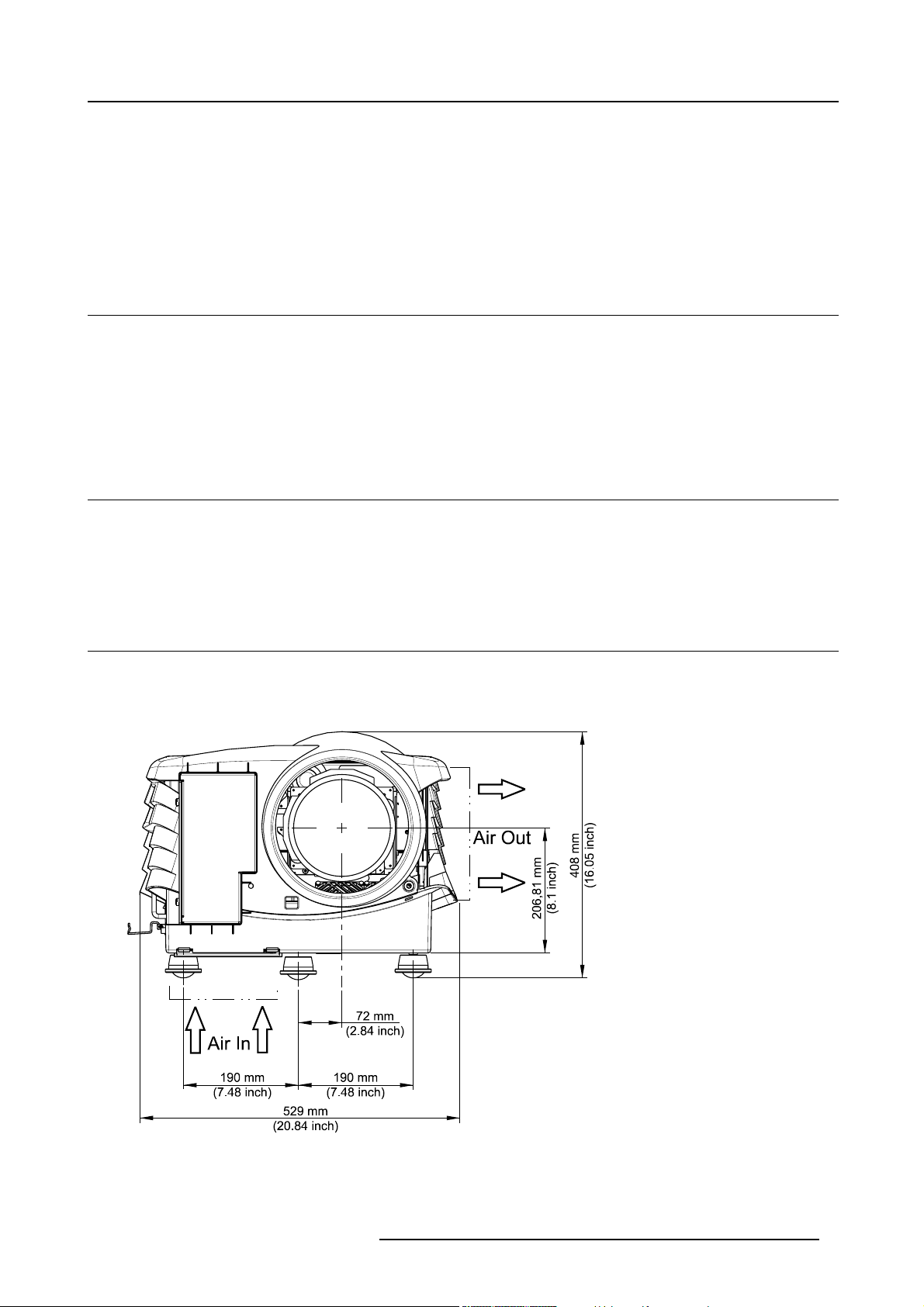
2.3 Dimensions
Dimensions
The dimensions of the projector are given in mm and inch (25,4mm = 1 inch).
Image 2-1
Front View Dimensions
R5976570 BARCO GALAXY WARP™ 25/03/2004 7
Page 12
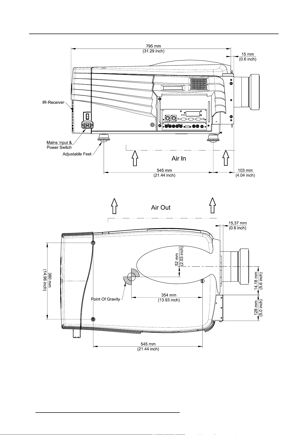
2. Packaging and Dimensions
Image 2-2
Left View Dimensions
Image 2-3
Top View Dimensions
8 R5976570 BARCO GALAXY WARP™ 25/03/2004
Page 13
3. INSTALLATION GUIDELINES
Overview
• General
• Projector Position
• Configuration
• Safety Area around the projector
• Re-adjusting the lamp position in the lamp casing
• Lenses
• Battery Installation in the RCU
The engines are non sealed versions.
3.1 General
WARNING: Before installing the projector, read first the safety instructions.
3. Installation Guidelines
Ambient Temperature Conditions.
Careful consideration of things such as image size, ambient light level, projector placement and type of screen to use are critical to
the optimum use of the projection system.
Max. ambient temperature : 35°C or 95 °F
Min. ambient temperature : 10 °C or 50 °F
The projector will not operate if ambient air temperature falls outside this range (10°C- 35°C or 50°F-95°F).
Storage temperature: -35°C to +65°C (-31°F to 149°F)
Humidity Conditions
Storage: 0 to 98 % RH Non-condensing
Operation: 0 to 95 % RH Non-condensing
CAUTION: Harmful Environmenta l Contamination Precaution
Environment
Do not install the projection system in a site near heat sources such as radiators or air ducts, or in a place subject to direct sunlight,
excessive dust or humidity. Be aware that room heat rises to the ceil
excessive.
ing; check that temperature near the installation site is not
Environment condition check
A projector must always be mounted in a manner which ensures the free flow of clean air into the projectors ventilation inlets. For
installations in environments where the projector is subject to airborne contaminants such as that produced by smoke machines or
similar (these deposit a thin layer of greasy residue upon the projectors internal optics and imaging electronic surfaces, degrading
performance), then it is highly advisable and desirable to have this contamination removed prior to it reaching the projectors clean
air supply. Devices or structures to extract or shield contaminated air well away from the projector are a prerequisite, if this is not a
feasible solution then measures to relocate the projector to a clean air environment should be considered.
Only ever use the manufacturer’s recommended cleaning kit which has been specifically designed for cleaning optical parts, never
use industrial strength cleaners on the projector’s optics as these will degrade optical coatings and damage sensitive optoelectronics
components. Failure to take suitable precautio
inants will culminate in extensive and irreversible ingrained optical damage. At this stage cleaning of the internal optical units will
be non-effective and impracticable. Damage of this nature is under no circumstances covered under the manufacturer’s warranty
and may deem the warranty null and void. In suc
repair. It is the clients responsibility to ensure at all times that the projector is protected from the harmful effects of hostile airborne
ns to protect the projector from the effects of persistent and prolonged air contam-
h a case the client shall be held solely responsible for all costs incurred during any
R5976570 BARCO GALAXY WARP™ 25/03/2004
9
Page 14
3. Installation Guidelines
particles in the environment of the projector. The manufacturer reserves the right to refuse repair if a projector has been subject to
wantful neglect, abandon or improper use.
Special Care for Laser Beams
Special care should be used when DLP projectors are used in the same room as performant laser equipment. Direct or indirect hitting
of a laser beam on to the lens can severely damage the Digital MicroMirror Devices™ in which case there is a loss of warranty
Which screen type ?
There are two major categories of screens used for projection equipment. Those used for front projected images and those for rear
projection applications.
Screens are rated by how much light they reflect (or transmit in the case of rear projection systems) given a determined amount
of light projected toward them. The ‘GAIN’ of a screen is the term used. Front and rear screens are both rated in terms of gain.
The gain of screens range from a white matte screen with a gain of 1 (x1) to a brushed aluminized screen with a gain of 10 (x10)
or more. The choice between higher and lower gain screens is largely a matter of personal preference and another consideration
called the Viewing angle. In considering the type of screen to choose, determine where the viewers will be located and go for the
highest gain screen possible. A high gain screen will provide a brighter picture but reduce the viewing angle. For more information
about screens, contact your local screen supplier.
What image size? How big should the image be?
The projector is designed for projecting an image size : min 1.00m (3.3ft) to max 15 m (49.2ft
conditions), with an aspect ratio of 4 to 3.
) (depending on the ambient light
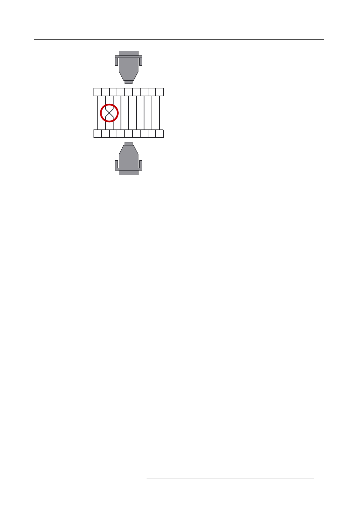
3.2 Projector Position
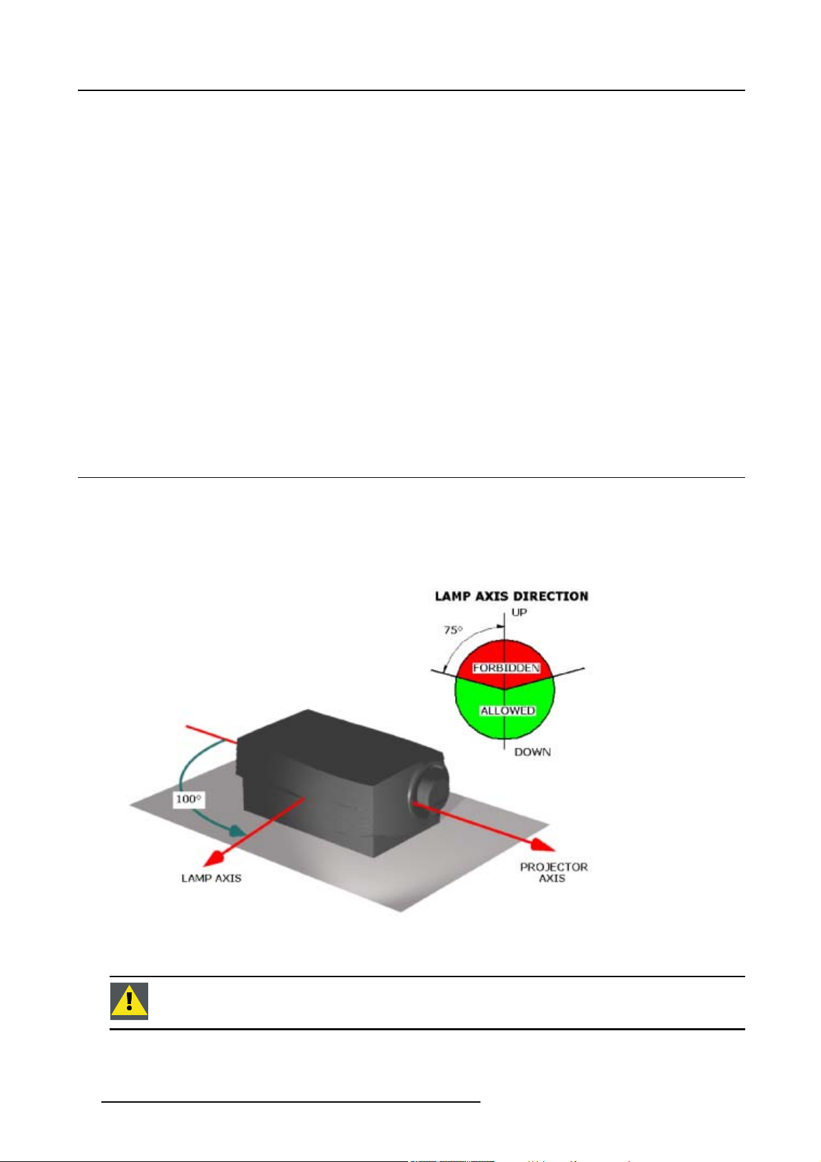
Projector Position Guidelines
The lamp axis, as it is drawn on this picture, can be oriented according to the specifications:
• pointed in any downward direction
• up to 15° in an upward position.
Image 3-1
Projector position
CAUTION: Never use the projector when turned with the inputs downwards.
10 R5976570 BARCO GALAXY WARP™ 25/03/2004
Page 15

3. Installation Guidelines
3.3 Configuration
Which configuration can be used?
The projector can be installed to project images in four different configurations.
• Front / Table
• Front / Ceiling
• Rear / Table
• Rear / Ceiling
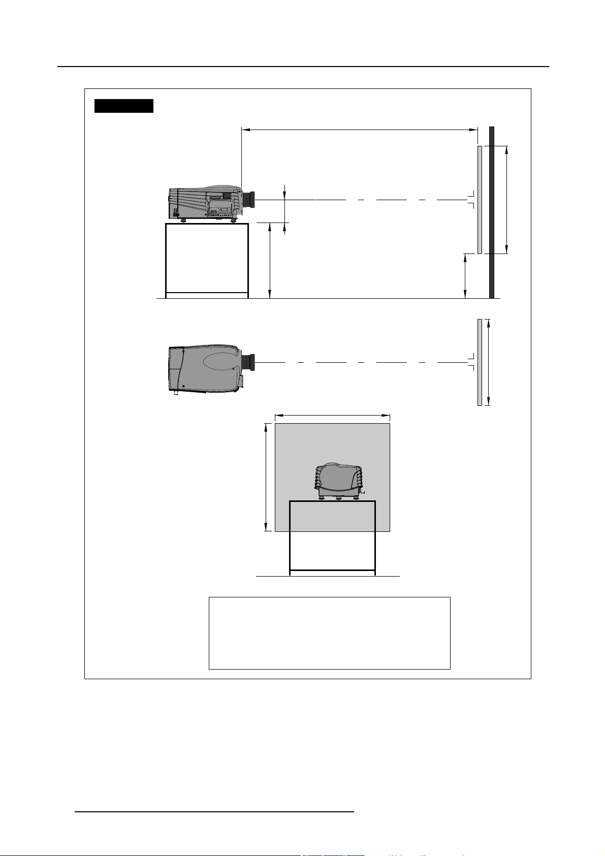
Positioning the projector
The Projector should be installed perpendicular with the screen on a distance PD and water leveled in both directions. The mounting
positions in following images are shown for a nominal lens position.
R5976570 BARCO GALAXY WARP™ 25/03/2004
11
Page 16
3. Installation Guidelines
Front Table
PD
Projector
Side view
Top view
Back view
Projector
SH
A
CD=SH/2+B-A
Optical axis projection lens
Floor
Optical axis projection lens
SW
SH
Screen
B
SW
Screen
Floor
Definitions on the abbreviation on the drawings:
A = Correction value.
B = Distance between floor and bottom of the screen.
CD = Total distance between projector and floor.
SW = Screen Width.
SH = Screen Height (Image height).
PD = Projector Distance, distance between screen and projector.
Image 3-2
Front Table Configuration
12 R5976570 BARCO GALAXY WARP™ 25/03/2004
Page 17
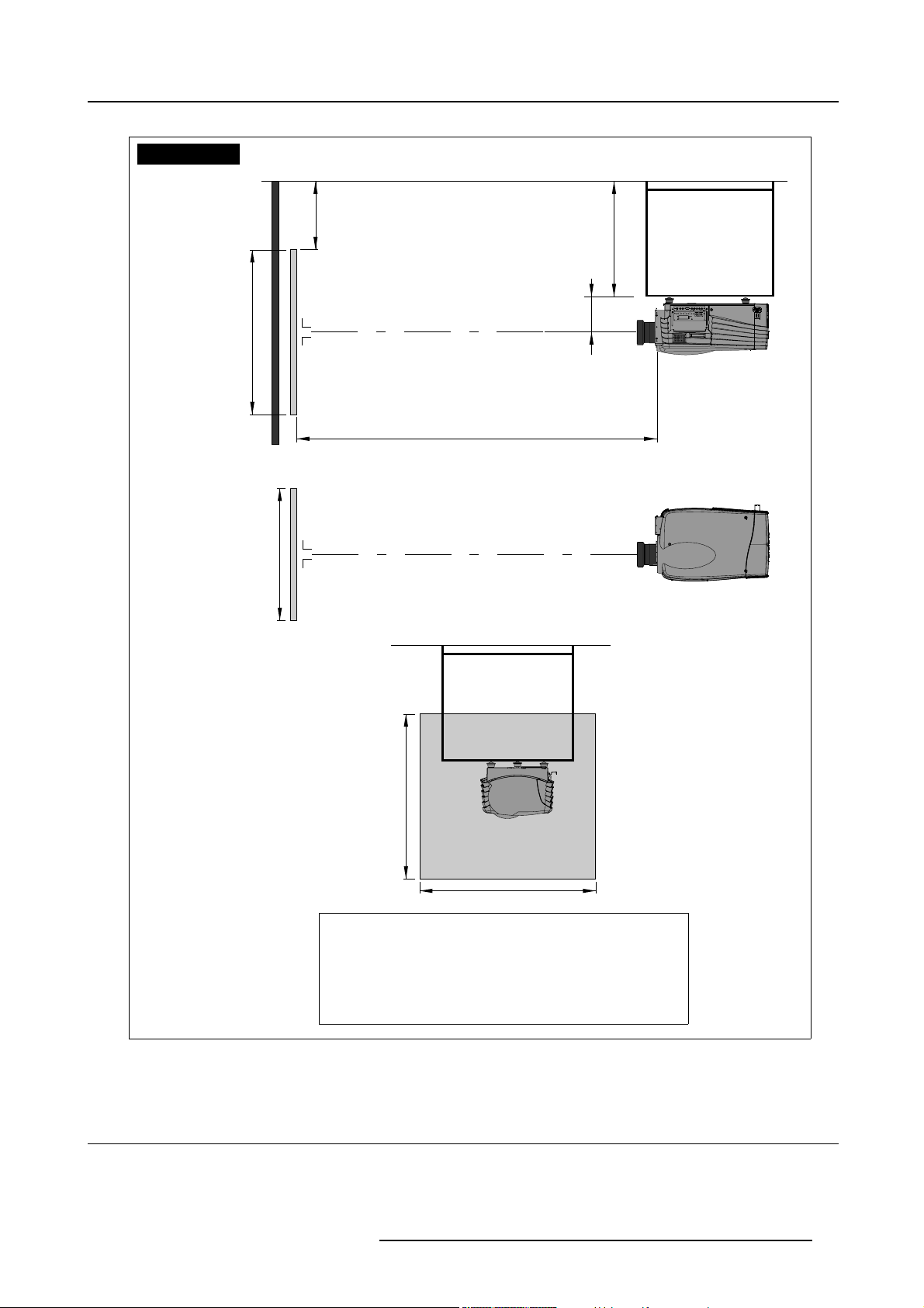
Front Ceiling
3. Installation Guidelines
Ceiling
B
CD=SH/2+B-A
Side view
Bottom view
SH
SW
Screen
Screen
Optical axis projection lens
PD
Optical axis projection lens
Ceiling
A
Projector
Projector
Back view
Image 3-3
Front Ceiling Configuration
Definitions on the abbreviation on the drawings:
A = Correction value.
B = Distance between ceiling and top of the screen.
CD = Total distance between projector and ceiling.
SW = Screen Width.
SH = Screen Height (Image height).
PD = Projector Distance, distance between screen and projector.
SH
SW
3.4 Safety Area around the projector
Safety Area
Make sure the projector is located so that the air inlets and outlets for the cooling system are not obstructed. Leave a safety area A
of about 1 meter on the left and the right side of the projector.
R5976570 BARCO GALAXY WARP™ 25/03/2004
13
Page 18
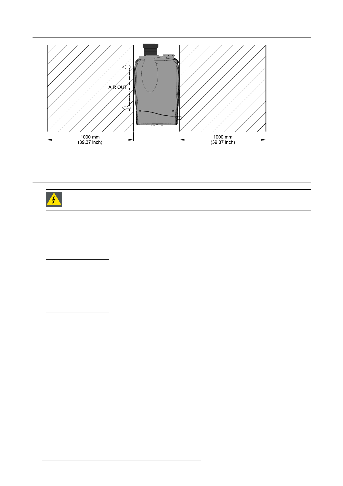
3. Installation Guidelines
Image 3-4
Safety Area
3.5 Re-adjusting the lamp position in the lamp casing
WARNING: As the projector has to be opened, this procedure has to be perfo
rmed by qualified service tech-
nician.
Why
With higher run times, the light output of the lamp will decrease, which results in a lower light output on the screen. This light output
decrease can be compensated by readjusting the position of the lamp.
A suggestion dialog box will be displayed when the projector is restarted after 100 hours and 250 hours. Once ENTER is pressed
when that box is open, this box will not be displayed again till the next alert point is reached.
Suggestion
Lamp runtime is
105 hours
It is advisable to
adjust the Z-axis
of the lamp to
obtain maximum
light output
(see owners manual)
<ENTER> to confirm
Menu 3-1
The user can now adjust the Z-axis by following the next procedure.
How to readjust.
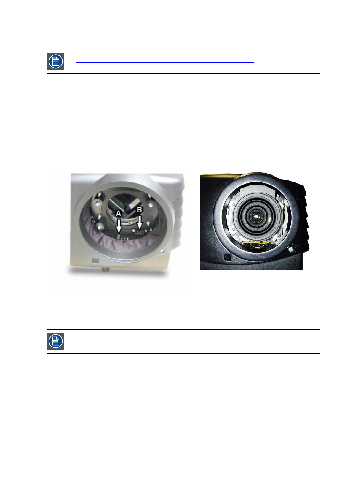
1. On the side of the inputs, turn the retaining bolt a quarter counter clockwise.
2. Flip the cover to the left side and take off. (image 3-5)
3. Start up the adjustment mode and select Service. (menu 3-2)
4. Select Lamp. The Z-axis indication (lamp men
5. Loosen the nut A (image 3-6)on the back of the lamp casing (nutdriver 10).
u in service mode) will be helpful while turning screw B . (menu 3-3)
14
R5976570 BARCO GALAXY WARP™ 25/03/2004
Page 19

3. Installation Guidelines
6. Adjust the screw B (image 3-6)with an Allen key by turning a little clockwise until the maximum light output is reached (the maximum value of the Z-AXIS indication on the lamp menu).
7. Fasten the nut on the back of the lamp casing to secure this position (nutdriver 10).
ADJUSTMENT MODE
Select a path from below :
RANDOM ACCESS
INSTALLATION
SERVICE
Select with ↑ or ↓
then <ENTER>
<EXIT> to return
Menu 3-2
Image 3-5
Lamp adjustment access
CHANGE PASSWORD
CHANGE LANGUAGE
CHANGE PROJ. ADDRESS
SERIAL COMMUNICATION
Select with ↑ or ↓
<EXIT> to return
Menu 3-3
SERVICE
IDENTIFICATION
NETWORK
LAMP
DIMMING
MORE...
then <ENTER>
LAMP
Constant Light output [OFF]
Using [RS port]
Mode [NORMAL]
Serial number : R101111
Article number : R9840xxx
Run time : 10 hours
Remaining run time : 490
hours
Number of strikes : 10
Z_AXIS : 100
Select with ↑ or ↓
then <ENTER>
<EXIT> to return.
Menu 3-4
A
Image 3-6
R5976570 BARCO GALAXY WARP™ 25/03/2004 15
Page 20
3. Installation Guidelines
CAUTION: Never turn the other screws ! These are factory aligned.
3.6 Lenses
Overview
• Lenses
• Lens selection
• Lens formulas
• Lens Installation
• Cleaning the lens
3.6.1 Lenses
Available lenses
TLD(1.6–2.0:1)
TLD(2.0–2.8:1)
TLD(2.8–5.0:1)
TLD(1.2:1)
TLD(0.8:1)
TLD(5.0–8.0:1)
R9840670
R9840680
R9840690
R9840770
R9840900
R9840910
3.6.2 Lens selection
How to select ?
1. Determine the required screen width.
2. Determine the approximate position of the projector in the projection room with regard to the screen and measure the projector-
screen distance (PD).
3. Use the lens formulas to find the bes
t corresponding PD with regard to the measured projector-screen distance for the required
screen width.
3.6.3 Lens formulas
Formulas
Metric formulas (meter) Inch formulas (inch)
TLD(0.8:1) PD=0.84xSW-0.05 PD=0.84SW-1.97
TLD(1.2:1) PD=1.20xSW-0.01 PD=1.20xSW-0.39
TLD(1.6–2.0:1) PD
TLD(2.0–2.8:1) PD
TLD(2.8–5.0:1) PD
TLD(5.0–8.0:1) PD
=1.59xSW-0.09
min
=2.00xSW-0.13
PD
max
=2.00xSW-0.17
min
=2.84xSW-0.24
PD
max
=2.80xSW-0.16
min
=5.10xSW-0.38
PD
max
=4.90xSW-0.01
min
=8.16xSW-0.29
PD
max
PD
=1.59xSW-3.54
min
=2.00xSW-5.12
PD
max
PD
=2.00xSW-6.69
min
=2.84xSW-9.45
PD
max
PD
=2.80xSW-6.30
min
=5.10xSW-14.96
PD
max
PD
=4.90xSW-0.39
min
=8.16xSW-11.42
PD
max
16 R5976570 BARCO GALAXY WARP™ 25/03/2004
Page 21
3. Installation Guidelines
Lens prog ram to calculate the projector distance is available on the BARCO web side :
ttp://www.barco.com/projection systems/customer services/lens program.asp
h
3.6.4 Lens Installation
How to install ?
Follow the next procedure:
1. Remove the foam rubber in the opening of the lens holder.
2. Take the lens assembly out of its packing material and remove the lens caps on both sides.
3. Move the handle (A) of the lens anchor system to the right. (image 3-7)
4. Push the lens, motors at the top, in the lens block gap horizontally, lining up the motor connector on the lens with the connector
on the lens block (B), until the lens clicks in the lens anchor system. (image 3-8)
Caution: On a table mounted projector, hold the projector when pushing the lens into the lens block to avoid sliding off from
the table.
Image 3-8
Mounted Lens
Image 3-7
Lens installation
3.6.5 Cleani
ng the lens
imize the possibility of damaging the optical coating or scratching exposed lens surface, we have de-
To min
veloped recommendations for cleaning the lens. FIRST, we recommend you try to remove any material from
the lens by blowing it off with clean, dry deionized air. DO NOT use any liquid to clean the lenses.
Necessary tools
To ra ys e eTMcloth (delivered together with the lens kit). Order number : R379058.
Howtocleanthelens?
Proceed as follow :
1. Always wipe lenses with a CLEAN Toraysee
2. Always wipe lenses in a single direction.
Warning: Do not wipe back and forwards across the lens surface as this tends to grind dirt into the coating.
3. Do not l
4. If smears occur when cleaning lenses, replace the cloth. Smears are the first indication of a dirty cloth.
eave cleaning cloth in either an open room or lab coat pocket, as doing so can contaminate the cloth.
TM
cloth.
R5976570 BARCO GALAXY WARP™ 25/03/2004
17
Page 22
3. Installation Guidelines
WARNING: Do not use fabric softener when washing the cleaning cloth or softener sheets when drying the
cloth.
Do not use liquid cleaners on the cloth as doing so will contamina te the cloth.
CAUTION: Other lenses can also be cleaned safely with this Toraysee
TM
cloth.
3.7 Battery Installation in the RCU
How are the batteries delivered ?
The batteries (not yet installed to save the battery life time) are delivered inside the plastic bag with the power cord.
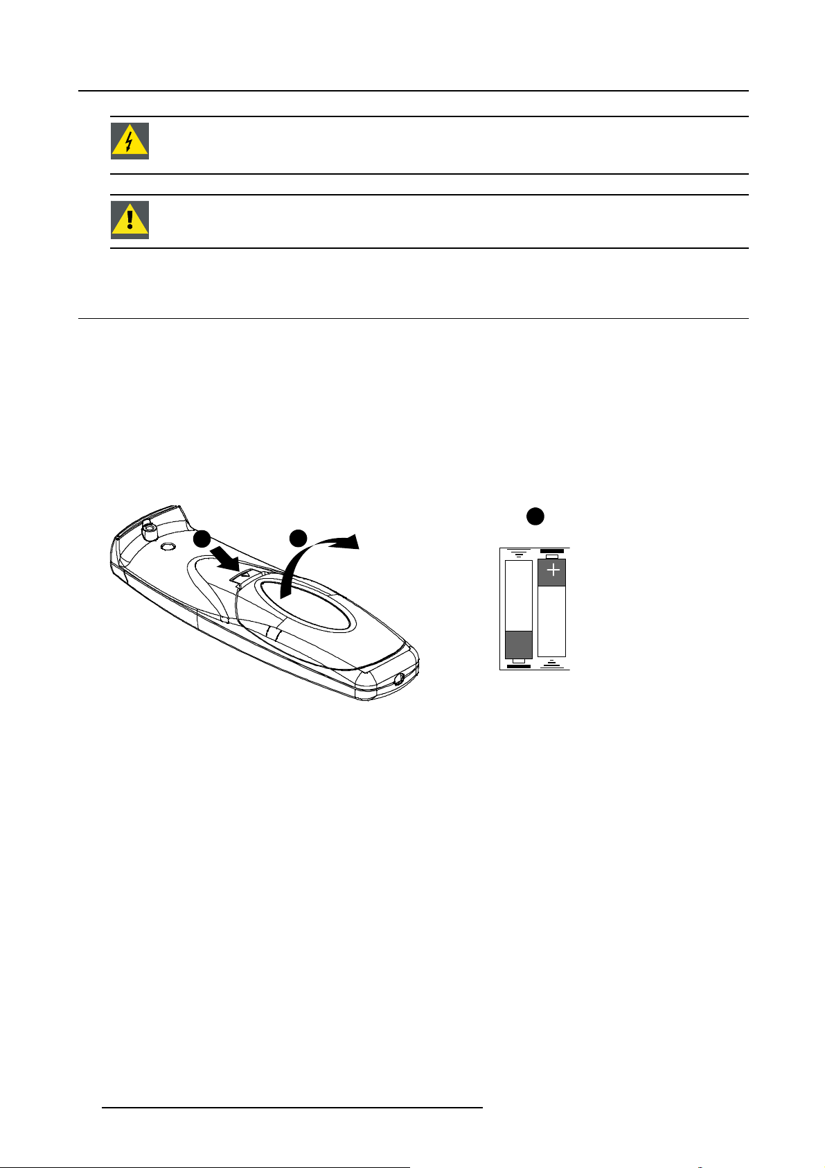
How to install
1. Remove the battery cover on the backside of the remote control by pushing the indicated handle a little towards the bottom of
the RCU.
2. Lift up the top side of the cover at the same time.
3. Insert the 2 new 1,5 V batteries as indicated in the RCU. (image 3-9)
4. Put the battery cover back on its place.
3
1
2
RCU Top
Image 3-9
Battery installation
+
18 R5976570 BARCO GALAXY WARP™ 25/03/2004
Page 23
4. Connections
4. CONNECTIONS
Overview
• Power connection
• Switching On
• Switching to standby
• Switching off
• Input Connections
• Communication Connections
• Stereo Connections
4.1 Power connection
AC Power cord connection
Use the supplied power cord to connect your projector to the wall outlet. Plug the female power connector into the male connector
at the left of the projector. The power input is 230 VAC.
Fuses
The projector is protected with an automatic circuit breaker of 15A which is built in into the power switch.
4.2 Switching On
Howtoswitchon?
1. Press the power switch to switch on the projector.
- When ’0’ is visible, the projector is switched off.
- When ’1’ is visible, the projector is switched on.
The projector starts in standby mode. The projector indication lamp is red.
Starting image projection
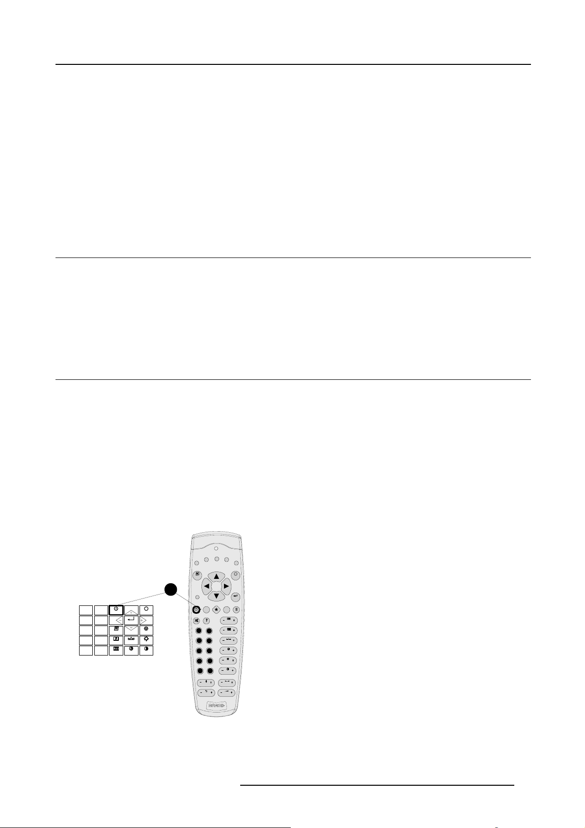
1. Press Stand by key once on the local keypad or on the remote control. (image 4-1)
The projector mode indication lamp will be green.
Or,
Press a digit button to select an input source.
F2F3F4
F1
ADJ
1
0
9
STANDBY
7
8
6
5
TEXT
3
4
SHARPN
2
1
PHASE
ENTER
COLOR
EXIT
PAUSE
TINT
BRIGHTN
CONTRAST
PAUSE
9
7
5
34
1
TREBLE
BASS
F5
EXIT
ENTER
TEXT
PHASE
0
SHARPN
8
TINT
6
COLOR
BRIGHTN
2
CONTR
BALANCE
VOL
Image 4-1
Stand by keys on RCU and local keypad
R5976570 BARCO GALAXY WARP™ 25/03/2004 19
Page 24

4. Connections
Lamp run time indication
The total lamp runtime for a safe operation is maximum 1000 or 1500 (depending on the lamp type) hours, do not use the lamp any
longer.
Operating the lamp longer than 1000 or 1500 (depending on the lamp type) hours may damage the projector.
When the maximum lamp runtime hours is reached, the following warning will be displayed, from then on, each time the projector is
started up, this warning will be displayed.
Remaining
Lamp run time
20h
Image 4-2
Press ENTER to remove this warning.
Always replace with the same type of lamp, call a BARCO authorized service technician for this lamp replacement.
CAUTION: Using a lamp for more than 1000 or 1500 (depending on the lamp type) hours is dangerous as the
lamp could explode.
Lamp Light Output Indication
When starting up the projector, the center lumens measurement is performed, when the lamp light output is lower than 50 % of the
initial value, the lamp light output warning will be displayed.
WARNING
Lamp run time is X hours
The light output of the lamp
than 50% of its initial value.
It is advisable to replace the
Menu 4-1
is less
lamp
before damage occurs.
<ENTER> to confirm
Press ENTER to remove this warning.
4.3 Switching to standby
Howtoswitchtostandby?
1. Press Standby to switch the projector to standby.
4.4 Switching off
How to switch off the projector?
1. Press first Standby.
2. Let cool down the projector until the fans stop b
3. Switch off the projector with the power switch.
20
lowing, at least 15 min.
R5976570 BARCO GALAXY WARP™ 25/03/2004
Page 25
4.5 Input Connections
Overview
• Input Facilities
• Input 1
• Input 2
• Inputs via RCVDS05
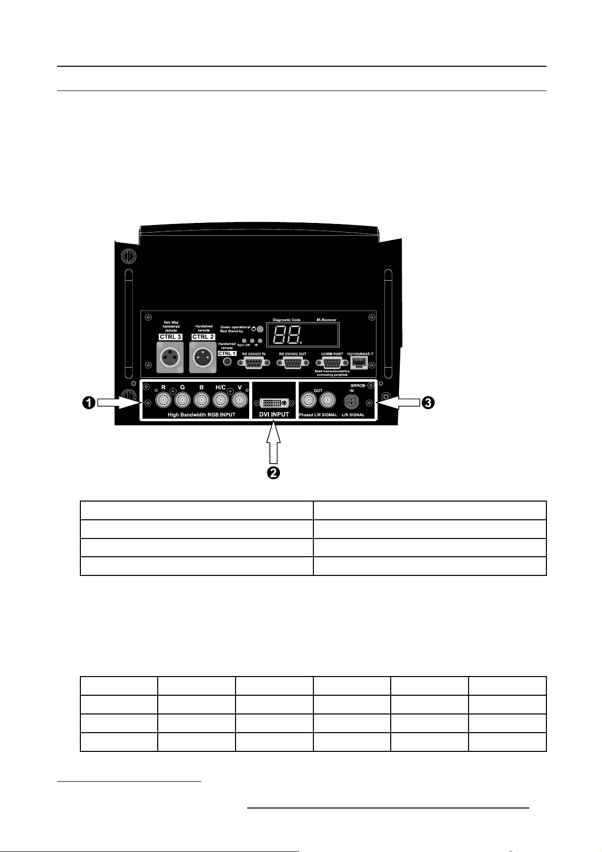
4.5.1 Input Facilities
Input Facilities Overview
4. Connections
Image 4-3
Input Facilities
Input Number
1
2 DVI Input
3
Table 4-1
Input Facilities
4.5.2 Input 1
Input 1 specifications
Input 1 has 5 BNC Input Terminals for 5 Cable Input.
Which signals can be connected to input 1?
Input S
RGBHV
RGBS
RGSB
ignal
R
R
R
R
G
G
G
G
S
Type Of Inpu t
High Bandwidth RGB Input
1
Left/Right Phasing Module
B H V
B H V
B
B
S
– –
–
1. Can not be used for Stereo Sources
R5976570 BARCO GALAXY WARP™ 25/03/2004 21
Page 26
4. Connections
How to select RGB on input 1?
1. Press the 1 key on the RCU or Local Keypad.
How to change the input slot setting?
1. Press ADJUST or ENTER key to start up the Adjustment Mode.
2. Push the cursor key ↑ or ↓ to select Installation. (menu 4-2)
3. Press ENTER to select.
The Installation menu will be displayed.
4. Push the cursor key ↑ or ↓ to select Input Slots. (menu 4-3)
5. Press ENTER to select.
The internal system will scan the inputs and displays the result in the Input Slots menu, only Input 1 is available. (menu 4-4)
6. Press ENTER to toggle between RGB-SS or RGB-SOG.
Menu 4-2
ADJUSTMENT MODE
Select a path from
below
RANDOM ACCESS
INSTALLATION
SERVICE
Source 1
Select with ↑ or ↓
then <ENTER>
Menu 4-3
INSTALLATION
INPUT SLOTS
NO SIGNAL
LENS
MENU POSITION [CENTER]
800-PERIPHERAL
CONFIGURATION
OSD COLOR
INTERNAL PATTERNS
Select with ↑ or ↓
then <ENTER>
<EXIT> to return
INPUT SLOTS
SLOT SELECTION [AUTOMATIC]
X SLOT 1 : RGB - SOG
- SLOT 2 : DVI
Select with ↑ or ↓
<ENTER> to toggle
<EXIT> to return
Menu 4-4
Possible indications on the input slot menu.
• RGS-SS [CV or HS&VS] = RGB analog signals, separate sync is composite sync or horizontal and vertical sync.
• RGB-SOG = RGB analog signals with sync on green.
When changing from an analog signal on the RGB Input to the DVI Input the indication led on the front panel of the module will
switch from the RGB Input to the DVI Input.
4.5.3 Input 2
Input 2 specifications
Input 2 has a DVI plug for DVI input.
Which signals can be connected to input 2?
DVI signals can be connected to the DVI input connector.
The DVI input can not be used for Stereo Sources.
Pin assignment for the DVI connector.
Pin 1
Pin 2
Pin 3
Pin 4
Pin 5
Pin 6
Pin 7
TMDS DATA2-
TMDS DATA2+
TMDS DATA2/4 Shield
TMDS DATA4-
TMDS DATA4+
DDC Clock
DDC Data
Pin 8 No connect Pin 20
22 R5976570 BARCO GALAXY WARP™ 25/03/2004
Pin 13
TMDS DATA3+
Pin 14 +5 Power
Pin 15
Ground (for +5V)
Pin 16 Hot Plug Detect
Pin 17
Pin 18
Pin 19
TMDS DATA0-
TMDS DATA0+
TMDS DATA0/5 Shield
TMDS DATA5-
Page 27
4. Connections
Pin 9
Pin 10
Pin 11
Pin 12
TMDS DATA1-
TMDS DATA1+
TMDS DATA1/3 Shield
TMDS DATA3-
Pin 21
Pin 22
Pin 23
Pin 24
TMDS DATA5+
TMDS Clock Shield
TMDS Clock+
TMDS Clock-
How to select DVI on Input 2?
1. Press the 2 key on the RCU or Local Keypad.
4.5.4 Inputs via RCVDS05
Overview
When using a RCVDS05, the input configuration must be as follows:
Slot 1 RGB/Component
Slot 2
When using a RCVDS05, it is recommended to use a 5-cable output module in the RCVDS. The outputs of this module has to be
connected to slot 1 of the projector.
Not Used
4.6 Communication Connections
Overview
• Linked System
• RS232 (RS422) connection
• Communication with peripherals
4.6.1 Linked System
CAUTION: Always use the Barco COM 800 Splitter, R9827941(240V) or R9827948(110V), when using the COM
800 protocol.
What can be done?
In a complex multi-channel setup, projectors can be controlled using the RS232 or COM800 Protocol.
CLO and Dynacolor™ can be controlled by both protocols, however by using the COM800 port for these 2 adjustments, the RS232
Port can still be used for general RS232 commands.
The following procedures will describe how to connect a RS232 Linked System and a COM800 Linked System.
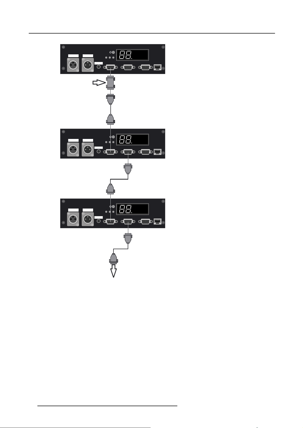
How to connect a RS232 Setup?
1. Connect a Null Modem connector to the RS232 Input of the master–projector. (image 4-4)
2. Connect the output of the Null Modem connector to the RS232 Input of the first slave–projector (image 4-4).
3. Continue by connecting the RS232 Output of the first slave-projector to the RS232 Input of the second slave–projector (im-
age 4-4).
4. Continue this daisy chain connection to connect all slave–projectors (image 4-4).
R5976570 BARCO GALAXY WARP™ 25/03/2004
23
Page 28
4. Connections
Null Modem Connector
Two Way
Hardwired
hardwired
CTRL 3 CTRL 2
remote
remote
Slave 1
Two Way
Hardwired
hardwired
CTRL 3 CTRL 2
remote
remote
Green operational
Red Stand-by
Hardwired
remote
CTRL 1
Green operational
Red Stand-by
Hardwired
remote
CTRL 1
Master
Sync OK IR
Sync OK IR
IR-RecieverDiagnostic Code
Read instructionsbefore
connecting periphals
IR-RecieverDiagnostic Code
Read instructionsbefore
connecting periphals
10(/100)BASE-TRS 232/422 IN RS 232/422 OUT COMM PORT
10(/100)BASE-TRS 232/422 IN RS 232/422 OUT COMM PORT
Slave 2
IR-RecieverDiagnostic Code
Read instructionsbefore
connecting periphals
10(/100)BASE-TRS 232/422 IN RS 232/422 OUT COMM PORT
Image 4-4
RS232 Setup
Two Way
Hardwired
hardwired
CTRL 3 CTRL 2
remote
remote
Green operational
Red Stand-by
Hardwired
remote
CTRL 1
Sync OK IR
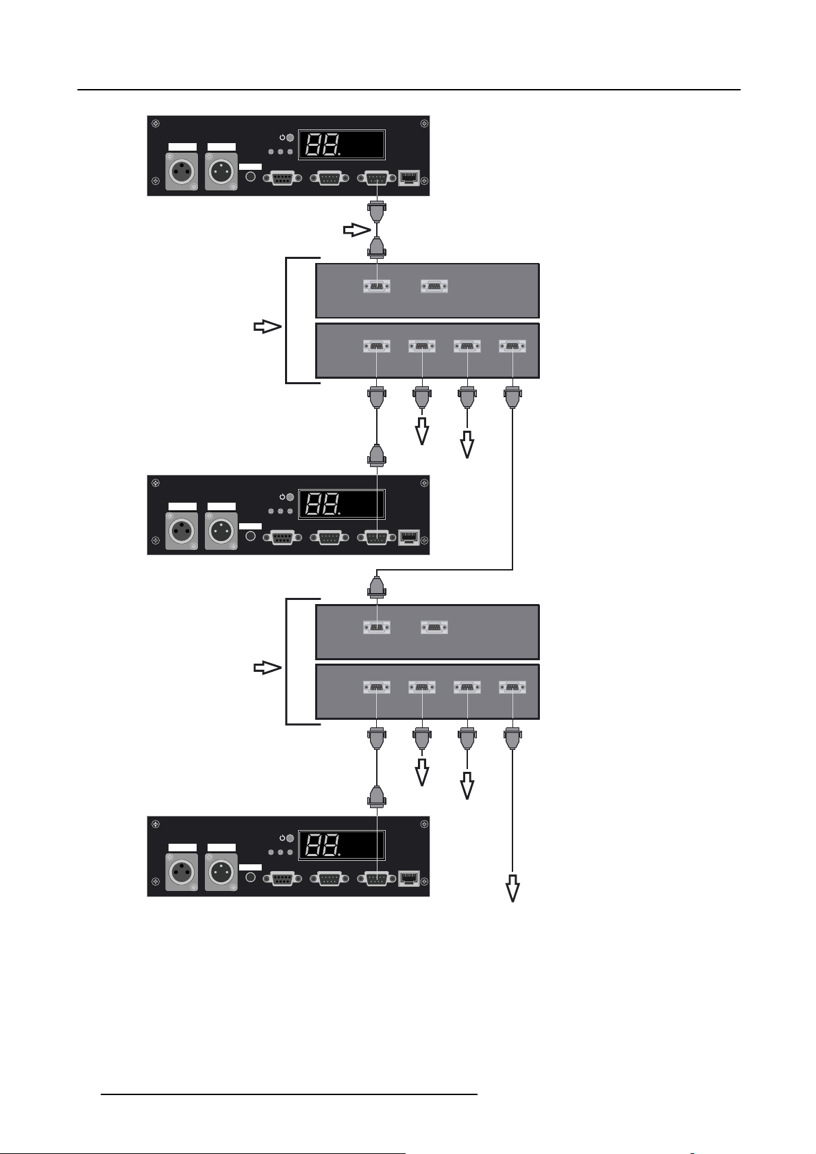
How to connect a COM800 Setup
Always use the Barco COM 800 Splitter, R9827941 (240V) or R9827948 (110V), when using the COM 800 protocol.
1. Use a data cable with at least 9
Null Modem Cable. (image 4-5)
2. Use the Custom Null Modem Cable to connect the COM 800 port of the master-projector to the ’To Switcher’ port on the frontside
of the COM 800 Splitter. (image 4-6)
3. Continue by connecting th
4. When dealing with more than 4 slave projectors, the ’To Proj.’ connectors on the backside of the COM 800 Splitter can also be
used to connect extra COM 800 Splitters (image 4-6).
cores and 2 DB9 female connectors, just cross the pin 2 and pin 3 connection to make a Custom
e slave projectors to the ’To Proj.’ connectors on the backside of the COM 800 Splitter (image 4-6).
24
R5976570 BARCO GALAXY WARP™ 25/03/2004
Page 29
DB9
Female
Connector
4. Connections
Pin Number
Pin Number
DB9
Female
Connector
Image 4-5
Make a Custom Null Modem Cable
23
4567891
456789123
R5976570 BARCO GALAXY WARP™ 25/03/2004 25
Page 30
4. Connections
r
Two Way
Hardwired
hardwired
CTRL 3 CTRL 2
remote
remote
Custom Null Modem Cable
COM 800 Splitter 1 (R9827941)
Two Way
Hardwired
hardwired
CTRL 3 CTRL 2
remote
remote
Green operational
Red Stand-by
Hardwired
remote
CTRL 1
Green operational
Red Stand-by
Hardwired
remote
CTRL 1
Sync OK IR
Slave 1
Sync OK IR
Front
Back
IR-RecieverDiagnostic Code
10(/100)BASE-TRS 232/422 IN RS 232/422 OUT COMM PORT
Read instructionsbefore
connecting periphals
TO SWITCHER
TO IR RECEIVER
COMM 800 Splitter
TO PROJ.1 TO PROJ.2 TO PROJ.3 TO PROJ.4
To Slave 2
To Slave 3
IR-RecieverDiagnostic Code
10(/100)BASE-TRS 232/422 IN RS 232/422 OUT COMM PORT
Read instructionsbefore
connecting periphals
COM 800 Splitter 2
Two Way
hardwired
remote
CTRL 3 CTRL 2
Image 4-6
Com 800 Connection
Hardwired
remote
Green operational
Red Stand-by
Hardwired
remote
CTRL 1
Slave 4
Sync OK IR
Front
Back
TO SWITCHER
TO IR RECEIVER
COMM 800 Splitter
TO PROJ.1 TO PROJ.2 TO PROJ.3 TO PROJ.4
To Slave 5
To Slave 6
IR-RecieverDiagnostic Code
10(/100)BASE-TRS 232/422 IN RS 232/422 OUT COMM PORT
Read instructionsbefore
connecting periphals
To next COMM 800 Splitte
26 R5976570 BARCO GALAXY WARP™ 25/03/2004
Page 31

4. Connections
4.6.2 RS232 (RS422) connection
Application
1. Remote control:
- easy adjustment of projector via an IBM PC (or compatible) or MAC connection.
- allow storage of multiple projector configurations and set ups.
- wide range of control possibilities.
- address range from 0 to 255.
2. Data communications: sending data to the projector or copying the data from the projector to a hard memory device (hard disc,
floppy, etc.).
4.6.3 Communication with peripherals
What is possible with an R CVDS05 connected.
• Up to 20 inputs with the RCVDS 05 and 90 inputs when RCVDS’s are linked via the expansion module.
• Serial communication with the projector.
• Remote control buttons on the RCVDS to control the projector (source selection and analog settings).
• Theselectedsourcenumberwillbedisplayedona2digitdisplayandtheselectedinput module will be indicated with a LED
on the rear.
For more information about the use of the RCVDS05, consult the owner’s manual of the RCVDS05.
What is possible with an VS05 connected.
The VS05 can switch up to 5 Composite Video sources, 3 Super Video sources and 1 RGB analog or component video source to
the projector. In addition, the audio signal proper to the source, can be switched to an audio amplifier. Order number : R9827890
For more information about the use of the VS05, consult the VS05 owner’s manual.
Connecting an IR Remote Receiver to the projector.
This infrared receiver unit makes it possible to control the projector from another room.
the IR receiver and the projector or the RCVDS. The control information from the RCU can now be sent to the IR Remote Receiver.
The IR Remote Receiver displays the selected source on a 7-segment display.
There is a communication line cable between
4.7 Stereo Connections
4.7.1 Single Channel Stereo Connections
4.7.1.1 Left/Right Phasing Module (Input 3)
Purpose
The Left/Right Phasing module allows us to manipulate the Stereo Emitter Signal that activate the Stereo Glasses.
How to connect the stereo emitter signal?
1. Connect the stereo emitter signal from the Image Generator to the Min
Note: On some IG’s, the Stereo Sync is already present in the Vertical Sync Signal.
2. Connect the IR emitters to the BNC output(s) of the Left/Right Phasing module.
i DIN input of the Left/Right Phasing module. (image 4-7)
R5976570 BARCO GALAXY WARP™ 25/03/2004
27
Page 32

4. Connections
Two Way
hardwired
CTRL 3 CTRL 2
Hardwired
Green operational
remote
remote
Red Stand-by
Hardwired
remote
CTRL 1
GRBH/CV
High Bandwidth RGB INPUT
Sync OK IR
DVI INPUT
IR Emitter
IR-RecieverDiagnostic Code
Read instructionsbefore
connecting periphals
10(/100)BASE-TRS 232/422 IN RS 232/422 OUT COMM PORT
INOUT
L/R SIGNALPhased L/R SIGNAL
Image Generator
IR Emitter
Image 4-7
Left/Right phasing module connections
4.7.2 Multi-Channel Stereo Connections
Overview
Active Glasses
•StereoSetUp
• Single CADWall Configuration
• Multiple CADWall (Showroom Installation)
4.7.2.1 Stereo Set Up
How to Set Up the Stereo Parameters?
The Transport Delay Setting must be the same on all Projectors.
The Stereo Phase must be same on all projectors, first adjust the Stereo phase on the projector where the IR Emitter signal comes
from, then put the same value on the other projectors as well.
For more detailed information on how to adjust these parameters (see "Stereo Options", page 111).
For more detailed information on synchronous /asynchronous mode (see "Forced Asynchronous", page 117).
28
R5976570 BARCO GALAXY WARP™ 25/03/2004
Page 33

4. Connections
4.7.2.2 Single CADWall Configuration
This chapter w ill describe the Stereo Connections for e.g. a Triple-Channel CADWall Setup.
How to connect the Stereo Signals in a Single CADWall Configuration?
1. Connect the Stereo Sync Signal coming from the IG to the Stereo In Mini DIN Input of all the projectors used in the Multi-Channel
Configuration. (image 4-8)
Note: On some IG’s, the Stereo Sync is already present in the Vertical Sync Signal.
Note: On some IG’s, the Stereo Sync is added to the Vertical Sync Signal.
2. Connect a ’Phased L/R Signal’ BNC Connector of the first projector to a ’Phased L/R Signal’ BNC Connector of the second
projector.
3. Continue until the Phased L/R Signal is connected ’Looped Through’ to all the projectors of the Multi-Channel Configuration.
4. Connect the ’IR Emitters to a free ’Phased L/R Signal’ BNC Connector.
All projectors will run on a common Stereo Sync (Phased L/R) Signal.
All Stereo IR Emitters will work in sync.
Projector 1
GRBH/CV
INOUT
High Bandwidth RGB INPUT
Projector 2
High Bandwidth RGB INPUT
Projector 3
High Bandwidth RGB INPUT
DVI INPUT
GRBH/CV
DVI INPUT
GRBH/CV
DVI INPUT
L/R SIGNALPhased L/R SIGNAL
Image Generator
INOUT
L/R SIGNALPhased L/R SIGNAL
INOUT
L/R SIGNALPhased L/R SIGNAL
Image 4-8
Stereo Signal Connections i
IR Emitter
Active Glasses
n a Single CADWall Configuration
IR Emitter
CadWall
R5976570 BARCO GALAXY WARP™ 25/03/2004 29
Page 34

4. Connections
4.7.2.3 Multiple CADWall (Showroom Installation)
This chapter willdescribe the Stereo Connections fore.g. asetup with 2Triple-Channel CADWalls in thesame
room e.g. a Showroom. Both CADWalls have there own IG. Weassume only the IG used by CADWall 1 has an
Synchronous Output Range.
It is possible to let CADWall 1 work synchronous with IG 1. The projectors of CADWall 2, that are in asynchronous mode, will then display the image at the frequency of IG 1.
Respect the following 2 rules when setting up such a configuration:
1. The IR Emitter must be connected to a projector running in Synchronous Mode.
2. All projectors connected to the synchronous IG must be set in Synchronous Mode.
3. All other projectors (CadWall2, CadWall3, ...) must be set in Forced Asynchronous Mode.
How to connect the Stereo Signals in a Multiple CADWall Configuration (Showroom Installation)?
1. The Stereo Sync Signal coming from both IG’s is connected to the Stereo In Mini DIN Inputs of both Multi-Channel Configurations.
(image 4-9)
Note: On some IG’s, the Stereo Sync is already present in the Vertical Sync Signal.
2. Connect a ’Phased L/R Signal’ BNC Connector of the first projector to a ’Phased L/R Signal’ BNC Connector of the second
projector.
3. Continue until the Phased L/R Signal is connected ’Looped Through’ to all the projectors of both Multi-Channel Configurations.
4. Connect the ’IR Emitters to a free ’Phased L/R Signal’ BNC Connector on a projector that is set t
All projectors will run on a common Stereo Sync (Phased L/R) Signal.
All Stereo IR Emitters in the room will work in sync.
o Synchronous Mode.
30
R5976570 BARCO GALAXY WARP™ 25/03/2004
Page 35

4. Connections
IR Emitter
S
y
n
c
h
r
o
n
o
u
s
IR Emitter IR Emitter
Active Glasses
CadWall 1 CadWall 2
CadWall 1 = Projector 1+2+3
Projector 1
GRBH/CV
High Bandwidth RGB INPUT
Projector 2
M
o
d
GRBH/CV
High Bandwidth RGB INPUT
e
Projector 3
GRBH/CV
High Bandwidth RGB INPUT
DVI INPUT
DVI INPUT
DVI INPUT
IR Emitter
Active Glasses
INOUT
L/R SIGNALPhased L/R SIGNAL
Image Generator 1
INOUT
L/R SIGNALPhased L/R SIGNAL
INOUT
L/R SIGNALPhased L/R SIGNAL
CadWall 2 = Projector 4+5+6
Projector 4
GRBH/CV
A
High Bandwidth RGB INPUT
DVI INPUT
s
y
F
n
o
c
r
h
c
r
e
o
d
n
o
u
s
Image 4-9
Stereo Signal Connections in a Multiple CADWall Configuration
M
o
d
e
Projector 5
GRBH/CV
High Bandwidth RGB INPUT
Projector 6
GRBH/CV
High Bandwidth RGB INPUT
DVI INPUT
DVI INPUT
INOUT
L/R SIGNALPhased L/R SIGNAL
Image Generator 2
INOUT
L/R SIGNALPhased L/R SIGNAL
INOUT
L/R SIGNALPhased L/R SIGNAL
R5976570 BARCO GALAXY WARP™ 25/03/2004 31
Page 36

4. Connections
32 R5976570 BARCO GALAXY WARP™ 25/03/2004
Page 37

5. Getting Started
5. GETTING STARTED
Overview
• RCU & Local keypad
• Terminology overview
• Operating the projector
• Quick Set Up Adjustments
•UsingtheRCU
• Controlling the Projector
5.1 RCU & Local keypad
How controlling the projector ?
The projector can be controlled by the local keypad or by the remote control unit.
Location of the local keypad ?
The local keypad is located on the input side of the projector.
Remote control functions.
This remote control includes a battery powered infrared (IR) transmitter that allows the user to control the projector remotely. This
remote control is used for source selection, control, adaptation and set up. It includes au
ness, Sharpness...) and settings.
Other functions of the remote control are :
• switching between stand by and operational mode.
• switching to "pause" (blanked picture, full power for immediate restarting)
• direct access to all connected sources.
tomatic storing of picture controls (Bright-
5.2 Terminology overview
Overview
The following table gives an overview of the different functionalities of the keys.
R5976570 BARCO GALAXY WARP™ 25/03/2004
33
Page 38

5. Getting Started
1
F3
F2
F1
F4
2
3
0
9
7
5
3
1
Image 5-1
RCU & Local Keypad overview
1 Function keys
STANDBY
8
6
4
SHARPN
2
TEXT
PHASE
ENTER
COLOR
TINT
EXIT
PAUSE
BRIGHTN
CONTRAST
user programmable keys with functions for direct access.
2 ADJ. Adjust key, to enter the adjustment mode
3 Address key
(recessed key), to enter the address of the projector (between 0 and 9). Press the recessed
address key with a pencil, followed by pressing one digit button between 0 and 9.
4
5
6
7
8
9
10
ADJ
PAUSE
9
7
5
34
1
TREBLE
BASS
TEXT
PHASE
0
SHARPN
8
TINT
6
COLOR
BRIGHTN
2
CONTR
BALANCE
VOL
EXIT
ENTER
F5
18
17
16
15
14
13
Stand-by
Pause/Park
Sharpness
12
11
Tint
Color
Brightness
Contrast
4
Selection key (*) to direct access the zoom/focus/shift functions.
5
PAU SE to stop projection for a short time, press ’PAUSE’. The image disappears but full power is
retained for immediate restarting.
6
STBY standby button, to start projector when the power switch is switched on and to switch off the
projector without switching off the power switch.
Attention : Switching to Standby. When the projector i
s running and you want to
go to standby, press the standby key for 2 seconds until the message ’Saving data,
please wait’ is displa yed. Do not press any longer on the standby key otherwise
the projector will restart.
7
MUTE not used
8
?
not used
9 Digit buttons direct input selection.
10 Audio controls not used
11 Picture controls use these buttons to obtain the desired color setting.
12 Phase
13 FREEZ
14 TEXT
used to remove the instability of the image.
press to freeze the projected image.
when adjusting one of the image, e.g. controls during a meeting, the displayed bar scale
can be removed by pressing ’TEXT’ key first. To re-display the bar scale on the screen,
press ’TEXT’ key again.
15 ENTER
to start up the adjustment mode or to confirm an adjustment or selection in the adjustment
mode.
34 R5976570 BARCO GALAXY WARP™ 25/03/2004
Page 39

16
Cursor keys to make menu selections when in the adjustment mode or to zoom/focus when the direct
access is active.
Comparison between the cursor keys and the use of the ’+’ and ’-’ keys on the local keypad
: RCU = local keypad
cursor key up = ’+’ key up
cursor key down = ’-’ key down
cursor key right = ’+’ key right
cursor key left = ’-’ key left
17 EXIT to leave the adjustment mode or to scroll upwards when in the adjustment mode.
18
RCU operation indication lights up when a button on the remote control is pressed. (This is a visual indicator to
check the operation of the remote control)
Table 5-1
5.3 Operating the projector
Overview
• Switching On
• Switching to standby
• Switching off
• Temperature error DMD
5. Getting Started
5.3.1 Switching On
Howtoswitchon?
1. Press the power switch to switch on
- When ’0’ is visible, the projector is switched off.
- When ’1’ is visible, the projector is switched on.
The projector starts in standby mode. The projector indication lamp is red.
Starting image projection
1. Press Stand by key once on the local
The projector mode indication lamp will be green.
Or,
Press a digit button to select an input source.
1
0
9
STANDBY
7
8
6
5
TEXT
3
4
SHARPN
2
1
PHASE
ENTER
COLOR
EXIT
PAUSE
TINT
BRIGHTN
CONTRAST
F1
ADJ
9
7
5
34
1
TREBLE
F2F3F4
PAUSE
0
8
6
BASS
the projector.
keypad or on the remote control. (image 5-2)
F5
EXIT
ENTER
TEXT
PHASE
SHARPN
TINT
COLOR
BRIGHTN
2
CONTR
BALANCE
VOL
Image 5-2
Standby key
R5976570 BARCO GALAXY WARP™ 25/03/2004 35
Page 40

5. Getting Started
Lamp Run time indication
see chapter "4. Connections", "Switching On", page 19
Lamp Light output indication
see chapter "4. Connections", "Switching On", page 19
5.3.2 Switching to standby
Howtoswitchtostandby?
1. Press Standby to switch the projector to standby.
Switching to Standby. Whenthe projector is runningand youwant to go tostandby, pressthe standbykey for
2 seconds until the message ’Savi ng data, please wait’ is displayed. Do not press any longer on the standby
key otherwise the projector will restart.
5.3.3 Switching off
How to switch off the projector?
1. Press first Standby.
2. Let cool down the projector until the fans stop blowing, at least 15 min.
3. Switch off the projector with the power switch.
5.3.4 Temperature error DMD
Overview
When the temperature of one of the DMD is too low or too high the projector will be switched automatically to standby. Before
switching to standby, the following message appears for 3 seconds on the screen : ’DMD out of operating temperature range.
Automatic shutdown is activated.’.
A ’-t’ appears on the LED display to indicate the user that the projector is swi
Operating temperature range of the DMD : +10°C and +35°C.
ERROR
DMD out of operating
temperature
range
Automatic shutdown is
activated
Menu 5-1
tched to standby due to DMD temperature problems.
5.4 Quick Set Up Adjustments
Overview
• Quick Lens Adjustment
• Quick OSD Color Change
5.4.1 Quick Lens Adjustment
What can be done?
This will adjust the zoom, focus, horizontal shift and vertical shift settings of the lens.
36
R5976570 BARCO GALAXY WARP™ 25/03/2004
Page 41

5. Getting Started
w
QuickLensAdjustment
1. Press the * key to start up the Quick Lens Adjustment menu.
The Zoom/Focus Adjustment menu will be displayed. (image 5-3)
2. Push the cursor key ↑ or ↓ to zoom and ← or → to focus the image.
3. Press ENTER to continue with the Shift Adjustment menu.
The Shift Adjustment menu will be displayed. (image 5-4)
4. Push the cursor key ↑ or ↓ to shift the image up or down and ← or → to shift the image left or right.
Note: Due to optical and mechanical limitations each lens type has its own shift capability, following illustration shows th e shift
capability for the available lenses in a Front / Table configuration. (image 5-5)
5. Press EXIT to leave the Quick Lens Adjustment menu.
LENS ADJUSTMENT ZOOM/FOCUS
ZOOM with or ,
FOCUS with or
<ENTER> to shift
<EXIT> to return
Image 5-3
Zoom/Focus adjustment menu
Image 5-4
Back Vie
Front / Table Configuration
Top
Left Right
Bottom
TLD 1.2 :1TLD 0.8 :1
59%
R15,7
LENS ADJUSTMENT SHIFT
SHIFT with or , or
<ENTER> to zoom/focus
<EXIT> to return
TLD 1.6 - 2.0 :1
TLD 2.0 - 2.8 :1
TLD 2.8 - 5.0 :1
TLD 5.0 - 8.0 :1
65%
R16,67
R12,74
20%
30%
20%
8%
Image 5-5
Shift Capability for the availab le lenses in a Front / Table configuration
5.4.2 Quick OSD Color Change
What can be done?
Quick change of the color of the highlighted items.
R5976570 BARCO GALAXY WARP™ 25/03/2004
45°
84%
100%
15%
15%
20%
50%17%
63%
20%
37
Page 42

5. Getting Started
The highlighted items can be displayed in:
•Red
• Green
•Yellow
How to change the On Screen Color
1. Press ADJUST or ENTER key to start up the Adjustment Mode.
2. Push the cursor key ↑ or ↓ to highlight Installation. (menu 5-2)
3. Press ENTER to select.
The OSD menu will be displayed. (menu 5-3)
4. Push the cursor key ↑ or ↓ to highlight the desired color.
5. Press ENTER to activate the selected color.
INSTALLATION
INPUT SLOTS
NO SIGNAL
MENU POSITION [CENTER]
800-PERIPHERAL
CONFIGURATION
OSD COLOR
INTERNAL PATTERNS
Select with ↑ or ↓
then <ENTER>
<EXIT> to return
Menu 5-2
LENS
Menu 5-3
OSD COLOR
HIGHLIGHTED ITEM
RED
GREEN
YELLOW
Select with ↑ or ↓
<ENTER> to accept
<EXIT> to return
5.5 Using the RCU
Pointing directly to the IR Sensor
When using the wireless remote control, make sure you are within the effective op
The remote control unit will not function properly if strong light strikes the sensor window or if there are obstacles between the remote
control unit and the projector IR sensor.
erating distance, in a straight line: 30m (100ft).
38
R5976570 BARCO GALAXY WARP™ 25/03/2004
Page 43

5. Getting Started
Image 5-6
RCUtoIRSensors
R5976570 BARCO GALAXY WARP™ 25/03/2004 39
Page 44

5. Getting Started
The IR Communication Leds
• Whenever the IR Sensor on the projector receives an IR signal the Red IR–Received Led will light up.
Image 5-7
IR-Received Led
• In case there is IR communication between the RCU and the projector the Green IR–Acknowledged Led will light up.
Image 5-8
IR-Acknowledged Led
Pointing to the Reflective Screen
1. Point the front of the RCU to th
40
e reflective screen surface. (image 5-9)
R5976570 BARCO GALAXY WARP™ 25/03/2004
Page 45

Image 5-9
RCU to Reflective Screen
Hardwired Remote Input
1. Plug one end of the remote cable in the connector on the bottom of the RCU.
2. Plug the other end in the connector in the front panel of the projector labelled CTRL 1. (image 5-10)
5. Getting Started
Image 5-10
RCU to Hardwired Remote Input
When using the Hardwired Remote Input the IR Sensor on the projector is disabled, the projector can only be
controlled by the hardwired co
nnected RCU.
R5976570 BARCO GALAXY WARP™ 25/03/2004 41
Page 46

5. Getting Started
5.6 Controlling the Projector
Overview
• Common Address
• Projector Address
• RCU Address
• Input Selection
• Picture Controls
• Menus on Local LCD Display
5.6.1 Common Address
What is Common Address 0?
Every projector has a Common Address default set to ’0’, when the RCU is set to address ’0’, every projector, without exception will
listen to the commands given by this RCU.
When to use Common Address 0?
• Since the RCU is default set to address ’0’, this is used by default to control the projector in a single projector setup.
• The Common Address is used to control multiple projectors using only a single RCU.
When to use Common Address 1?
Most RCU’s used by other electronic equipment are set to address ’0’, to disable the interference of other RCU’s the Common
Address of the projector(s) can be set to ’1’. When the projector’s RCU is set to address ’1’, every projector, without exception will
listen to the commands given by this RCU.
How to set the Common Address?
See ’Change Common Address’ in the chapter ’Service Mode’.
5.6.2 Projector Address
When to use the Projector Address?
To control a separate projector in a multiple projector setup.
What is the Projector Address?
Each projector can be set to an individual Projector Address, this can be set between ’0’ and ’255’.
Projector Address
0–9
0–255
Regardless of the Projector Address, the projector will still respond to a RCU set to address ’0’ or ’1’ through
the Common Address.
Controlled by
RCU
Computer (IBM PC or compatible, Apple, ...)
How to set the Projector Address?
See ’Change Projector Address’ in chapter ’Service Mode’.
5.6.3 RCU Address
The RCU Address can be any digit between ’0’ and ’9’.
42 R5976570 BARCO GALAXY WARP™ 25/03/2004
Page 47

5. Getting Started
How to set the RCU Address?
1. Press the recessed Address key with a pencil. (image 5-11)
The Projector Address for every projector in the room will be displayed as a 3 digit code in a text box on the screen.
2. Enter the RCU Address by pressing a single digit key, within 5 seconds after pushing the address key.
Note: If the Projector Address displays ’003’ press the digit key 3 on the RCU. Do not enter the 3 digit code ’003’, this will set
the RCU to address ’0’.
Note: If no digit is entered within 5 seconds the RCU will return to the default ’0’ address.
F2F3F4
F1
F5
EXIT
ADJ
ENTER
PAUSE
TEXT
PHASE
9
0
SHARPN
8
7
TINT
5
6
COLOR
34
BRIGHTN
2
1
CONTR
TREBLE BALANCE
BASS
VOL
Image 5-11
Address K ey
5.6.4 Input Selection
How to select the desired input?
1. Press the digit key on the RCU corresponding with the desired input.
Digit Key
1
Type of Input
5x BNC Cable Input
2 DVI Input
Ta bl e 5- 3
Input Selection
5.6.5 Picture Controls
How to use Picture Controls?
1. Push the + or – key of the desired Picture Control e.g. ’brightness’. (image 5-12)
A text box with a bar scale indication and function name of the control, e.g. ’brightness’ appears on the screen. The length of
the bar scale and the value of the numeric indication indicate the current memorized setting for this source. The length of the bar
scale and the value of the numeric indication will change whenever an adjustment is made. (image 5-13)
F1
ADJ
9
7
56
34
1
TREBLE BALANCE
F2F3F4
PAUSE
0
8
2
BASS
F5
EXIT
ENTER
TEXT
PHASE
SHARPN
TINT
COLOR
BRIGHTN
CONTR
VOL
BRIGHTN
Image 5-13
Barscale indication
Brightness 50
Image 5-12
Picture Control key
R5976570 BARCO GALAXY WARP™ 25/03/2004 43
Page 48

5. Getting Started
Overview of the Picture Controls
Sharpness Use the + button for a sharper picture.
Use the - button for a softer picture.
Tint Not used
Color
Brightness
Contrast A correct ’contrast’ setting is important for good image reproduction. Adjust the contrast to the level
Not used
A correct ’brightness’ setting is important for good image reproduction.
Use the + button for a higher brightness.
Use the - button for a lower brightness.
you prefer, according to room lighting conditions.
Use the + button for a higher contrast.
Use the - button for lower contrast.
5.6.6 Menus on Local LCD Display
Overview
When text is ’off’, no menus will be displayed on the projection screen. But on the local LCD display, it is still possible to scroll
through the menus. The menus will be displ
Adjustments can be done while the projector is running without projecting the disturbing menus on the screen.
Use the cursor keys to scroll through the menus and press ENTER to activate the displayed menu.
ayed line by line in the same order as they were displayed on the projection screen.
44
R5976570 BARCO GALAXY WARP™ 25/03/2004
Page 49

6. RANDOM ACCESS
Overview
• Random Access Overview
• Starting Up Random Access
• File Service
• Picture Tuning
• Geometry
• Stereo Options
6.1 Random Access Overview
Random Access Overview
• File Service
- Load
-EditWarp1
-EditWarp2
- Rename
- Copy
-Delete
- Options
o
File Sort [Name/Index]
o
File Load [Automatic/Manual]
o
Serial File Load [On/Off]
• Picture Tuning
- Gamma
- Input Balance
o
White Balance
o
Black Balance
o
Default
- Windowing
o
Blanking
o
Shift
o
Size
o
Geo Soft Edge [On/Off]
2
6. Random Access
2. Only available in Stereo Mode
R5976570 BARCO GALAXY WARP™ 25/03/2004 45
Page 50

6. Random Access
• Geometry
- Load
-Edit
o
Coarse
o
Linearity
o
Fine
o
Shift
o
Transport Delay
o
Mode [Automatic/Manual]
o
Transport Delay Setting
o
Blanking/Soft Edge (Optional)
o
Active [On/Off]
o
Shape
o
Soft Edge (Optional)
o
Reset
o
Coarse
o
Linearity
o
Fine
o
Blanking/Soft Edge (Optional)
o
o
o
All
- Rename
- Copy
-Delete
• Stereo Options
- Stereo Phase
- Invert Stereo [Yes/No]
- Master Channel [Left/Right]
- Stereo Mode [Active/Passive]
-DarkTime
- Forced Asynchronous [Yes/No]
Soft Edge (Optional)
All
2
6.2 Starting Up Random Access
How to start up Random Access?
1. Press ADJUST or ENTER key to start up the Ad justment Mode. (image 6-1)
The Adjustment Mode menu will be displayed.
2. Push the cursor key ↑ or ↓ to select Random Access. (menu 6-1)
3. Press ENTER to select.
The Random Access menu will be displayed. (menu 6-2)
Menu 6-1
ADJUSTMENT MODE
Select a path from
below
RANDOM ACCESS
INSTALLATION
SERVICE
Source 1
Select with ↑ or ↓
then <ENTER>
Menu 6-2
RANDOM ACCESS
ADJUSTMENT MODE
FILE SERVICE
PICTURE TUNING
GEOMETRY
STEREO OPTIONS
Select with ↑ or ↓
then <ENTER>
<EXIT> to return
46 R5976570 BARCO GALAXY WARP™ 25/03/2004
Page 51

Image 6-1
Adjust or Enter key
6.3 File Service
Overview
• File annotation
• Possible file manipulations
• StartingUpFileService
• Load File
•EditWARP1
•EditWARP2
• Changing the settings
• Correct value
•EditWARP2File
• Rename File
• Copy File
• Delete File
• File Options
6. Random Access
6.3.1 File annotation
How a file is built up
The file notation on a menu is built up in different parts. Let us have a look to t
Take the following notation : xxxxxxxx.eee n ppppXppppi
xxxxxxxx
eee
n
ppppXpppp active pixel rating
i i or blank
Table 6-1
base name, 8 characters
file extension
first character C : custom made file
first character S : standard file
The second and third character is used for a following number (= file
index). The file index for custom files : 01 to 20.
source number
i = interlaced file
blank = not interlaced
hese parts.
R5976570 BARCO GALAXY WARP™ 25/03/2004 47
Page 52

6. Random Access
6.3.2 Possible file manipulations
Connecting a new source.
Before using a new source, a correct file has to be installed. The projector’s memory contains a list of files corresponding to the most
used sources. When the new source corresponds with one of these files, the file can be loaded and saved for future use. When
there is a little difference, the file can also be loaded and then edited until the source specs are reached.
File loading can be done automatically. Files with a ~ in front of the file name are temporary files. These files
will be deleted when switching to another source.
Possible file Manipulations
The following file manipulations are possible :
• Load : installation of a file for a new source.
• Edit : editing a loaded file to the source specs.
• Rename : renaming a file.
• Copy : copying a file.
• Delete : deleting a file
• Options : way of sorting the files.
6.3.3 Starting Up File Service
How to Start Up File Service?
1. Push the cursor key ↑ or ↓ to highlight File Service. (menu 6-3)
2. Press ENTER to select.
The File Service menu will be displayed. (menu 6-4)
Menu 6-3
RANDOM ACCESS
ADJUSTMENT MODE
FILE SERVICE
PICTURE TUNING
GEOMETRY
STEREO OPTIONS
Select with ↑ or ↓
then <ENTER>
<EXIT> to return
Menu 6-4
FILE SERVICE
EDIT WARP1
EDIT WARP2
Select with ↑ or ↓
then <ENTER>
<EXIT> to return
6.3.4 Load File
How to Start Up Load File?
1. Push the cursor key ↑ or ↓ to highlight Lo ad. (menu 6-5)
2. Press ENTER to select.
The Load menu displays the corresponding files depending on the installed filter. (menu 6-6)
FILE SERVICE
LOAD
EDIT WARP1
EDIT WARP2
RENAME
COPY
DELETE
OPTIONS
Select with ↑ or ↓
then <ENTER>
<EXIT> to return
F
xga_60.s01 1 1024x768
xga_60.c01 1 1024x760
xga_60.c02 1 1024x760
xga_60.c03 1 1024x760
---------------------------Active file : xga_60.c04
LOAD FILE
FILTER LIST [All]
ilename Scr resolution
Select with ↑ or ↓ , →
<ENTER> to accept
<EXIT> to return
LOAD
RENAME
COPY
DELETE
OPTIONS
Menu 6-5
Menu 6-6
48 R5976570 BARCO GALAXY WARP™ 25/03/2004
Page 53

How to change the Filter List Setting?
1. Push the cursor key ↑ or ↓ to to highlight filter list.
2. Press ENTER to toggle the annotation between brackets.
6. Random Access
[ALL]
[FIT]
all files that can be loaded will be displayed
only the best fitting files will be displayed (with a distinction of ± 2 lines and line duration of ± 300 ns, if nothing
is found within this small area, the projector continues searching until it finds something).
How to Load a File?
1. Push the cursor key ↑ or ↓ to select the best fitting file. (menu 6-7)
2. Press ENTER to select.
A confirm Load file menu will be displayed with the newly created file and the one on which the new file is based on. (menu 6-8)
3. Press ENTER to confirm the new creation or EXIT to return to the load file menu.
LOAD FILE
FILTER LIST [All]
ilename Scr resolution
F
xga_60.s01 1 1024x768
xga_60.c01 1 1024x760
xga_60.c02 1 1024x760
xga_60.c03 1 1024x760
---------------------------Active file : xga_60.c04
Select with ↑ or ↓ , →
<ENTER> to accept
<EXIT> to return
Menu 6-7
During a load file, the actual file is d
Menu 6-8
CONFIRM
LOAD FILE
create file
xga_60.c02
based on file
xga_60.s01?
<ENTER> to return
<EXIT> to return
isplayed next to the indication Active file.
When scrolling through the files, the image will be adapted according to the settings of the selected file ( on
line adaptation ) .
The image is not perfect?
If the displayed image is not correct after selecting the best fitting file, go to the Edit WARP1 menu, select the active file and change
the File Settings.
6.3.5 Edit WARP1
What can be done?
• When a Mono Image is proje
• When a Stereo Image is projected, within this menu, it is possible to change the File Settings for the Left Image of a selected
source file.
cted, within this menu, it is possible to change the File Settings of a selected source file.
R5976570 BARCO GALAXY WARP™ 25/03/2004
49
Page 54

6. Random Access
How to Start Up Edit WARP1 File?
1. Push the cursor key ↑ or ↓ to highlight Edit WARP1. (menu 6-9)
2. Press ENTER to select.
The Edit file adaptation menu will be displayed. (menu 6-10)
3. Select the file which must be edited (mostly the active file).
The file name will be displayed in the upper right corner. (menu 6-11)
Menu 6-9
FILE SERVICE
LOAD
EDIT WARP1
EDIT WARP2
RENAME
COPY
DELETE
OPTIONS
Select with ↑ or ↓
then <ENTER>
<EXIT> to return
F
xga_60.s01 1 1024x768
xga_60.c01 1 1024x760
xga_60.c02 1 1024x760
xga_60.c03 1 1024x760
---------------------------Active file : xga_60.c04
Menu 6-10
EDIT FILE
ilename Scr resolution
Select with ↑ or ↓ , →
<ENTER> to accept
<EXIT> to return
EDIT FILE xga_60.c02
HORIZONTAL
TOTAL 1344 PIXELS
ACTIVE 1024 PIXELS
START 266 PIXELS
PERIOD 16.625 µs
VERTICAL (FIELD)
TOTAL 800 LINES
ACTIVE 760 LINES
START 37 LINES
READ AMDS
OPTIONS
↑ , ↓ , ← , → <ENTER>, <EXIT>
Menu 6-11
6.3.6 Edit WARP2
When available?
The Edit WARP2 adjustment is only available when a Stereo Image is projected, when projecting a Mono Image this item will be
grayed out in the File Service menu.
What can be done?
When a Stereo Image is projected, within this menu, it is possible to change the File Settings for the Right Image of a selected
source file.
How to Start Up Edit WARP2 File?
1. Push the cursor key ↑ or ↓ to highlight Edit WARP2. (menu 6-12)
2. Press ENTER to select.
The Edit file adaptation menu will be displayed. (menu 6-13)
3. Select the file which must be edited (mostly the active file).
The file name will be displayed in the upper right corner. (menu 6-14)
Menu 6-12
FILE SERVICE
LOAD
EDIT WARP1
EDIT WARP2
RENAME
COPY
DELETE
OPTIONS
Select with ↑ or ↓
then <ENTER>
<EXIT> to return
F
xga_60.s01 1 1024x768
xga_60.c01 1 1024x760
xga_60.c02 1 1024x760
xga_60.c03 1 1024x760
---------------------------Active file : xga_60.c04
Menu 6-13
EDIT FILE
ilename Scr resolution
Select with ↑ or ↓ , →
<ENTER> to accept
<EXIT> to return
EDIT FILE xga_60.c02
HORIZONTAL
TOTAL 1344 PIXELS
ACTIVE 1024 PIXELS
START 266 PIXELS
PERIOD 16.625 µs
VERTICAL (FIELD)
TOTAL 800 LINES
ACTIVE 760 LINES
START 37 LINES
READ AMDS
OPTIONS
↑ , ↓ , ← , → <ENTER>, <EXIT>
Menu 6-14
6.3.7 Changing the settings
Different methods
The 3 different methods to change a setting will be described hereafter. These methods are:
• with the numeric keys on the remote control.
• with the arrow keys selecting the changing digit.
• with the arrow keys counting up or down.
50
R5976570 BARCO GALAXY WARP™ 25/03/2004
Page 55

How to change a setting with the numeric keys?
1. Push the cursor key ↑ or ↓ to highlight an item.
The color of the selected item will change.
2. Press EN TER to activate the digits.
3. Enter directly with the numeric keys on the RCU or local keypad the new value.
How to change a setting with the cursor keys?
1. Push the cursor key ↑ or ↓ to highlight an item.
The color of the selected item will change.
2. Press EN TER to activate the digits.
3. Push the cursor key ← or → to select the changing digit.
4. Push the cursor key ↑ or ↓ to scroll to the desired digit.
5. When finished, press ENTER to confirm.
How to change a setting with the cursor keys and counting up or down?
1. Push the cursor key ↑ or ↓ to highlight an item.
The color of the selected item will change.
2. Press ENTER to activate.
3. Counting up or down by pushing the cursor key ← or →.
6. Random Access
6.3.8 Correct value
What is already available during start up?
During the installation of a file with LOAD, the horizontal period, the total number of vertical lines and the interlaced mode are
automatically measured and filled in, in the menu table. These values will be available w
active file.
hen starting up the EDIT procedure of an
CAUTION: Do not adjust these settings on an active file, they are used to identify the input source file.
How to find the correct values for the item in the Edit file menu?
Horizontal Total Pixels
Active Pixels
Horizontal Start number of pixels between the beginning of the input signal and the start of the
Horizontal Period
If the value for "Horizontal Total Pixels" is wrong sampling mistakes (small vertical
bars with noisy and unsharp data in the projected image) will be seen especiall
high resolution images.
Use a pixel on/off pattern when adjusting the Horizontal Total Pixels.
Select "Total" and adjust the pixel quantity. Adjust for zero bars.
hint: if the number of bars increase, adjust in the other direction.
The "Active Pixels" : determine the width of the window on the screen. This value is
normally given in the source specifications. If not, adjust until full image is displayed
(no missing pixels).
video information in the signal.
already filled in with the correct value when active file.
yin
Ver ti cal Tota l Lin es
Active Lines
Vertical Start number of lines between the start of the input signal and start of the image on
R5976570 BARCO GALAXY WARP™ 25/03/2004 51
already filled when an active file is selected to be edited
number of horizontal lines determining the height of the projected image. This value
is normally given in the specification of the source. If not, adjust until full image
height is displayed (no missing lines)
the screen.
Page 56

6. Random Access
Interlaced [On] or [Off] this selection is automatically filled when active file has to be edited. If the image is
wrong due to mismeasurement, use the ENTER key to toggle between [On] and
[Off]. (for interlaced images, 1 frame contains 2 fields).
Read AMDS AMDS = automatic mode detection & synchronization
During the installation of a file with LOAD, the system automatically measured the
horizontal period, the total vertical lines and the interlaced mode. When selecting
Read AMDS, the system remeasures the above indicated items.
How to install the correct settings for the options in the E dit file menu.
EDIT FILE OPTIONS
Source number 1
Clamp position [leading]
Clamp delay 0
Clamp width 10
Field polarity [pos]
Field select [both]
Vertical refresh [sync]
Vertical sync polarity [leading]
Select with ↑ or ↓
<ENTER> to toggle
↑ or ↓ to change value
<EXIT> to return
Menu 6-15
Source number The source number of a non-active source can be changed to any other source number. This makes
itpossibletocreateafilefo
Clamp position Clamping determines the black level of the signal. The clamp pulse can be related to the leading or
the trailing edge of the sync pulse. Use the ENTER key to toggle between [leading] and [trailing].
Clamp delay The time between the leading ed
any value between 0 and 255. Change the value by pushing the cursor key ↑ or ↓.
r future source numbers.
ge of the clamp pulse and the locked edge of the sync pulse. Can be
Clamp width The width of the clamp pulse can be any value between 0 and 255. Change the value by pushing
the cursor key ↑ or ↓.
Leading edge
Trailinging edge
Sync
pulse
Clamp
pulse
Clamp
Clamp
delay
width
Image 6-2
Example for Clamp position [trailing]
Field polarity
The field polarity function is used for interlaced images. Both rasters of the image could be shifted in a
wrong way (double lines are visible in the image). This can be corrected by forcing the field polarity to
[neg] or [pos]. Use the ENTER key to toggle between [pos] and [neg].
Field select
Default [both]
The field select is only used for interlaced images. One frame of an interlaced image contains two
fields, an even and an odd field. The choice exists to project [both] fields on the screen or only the
] or [odd] field.
[even
Use the ENTER key to toggle between [both], [even] and [odd].
If the active Stereo Compatibility Option is installed, the field select parameter will be changed
into a [left] and [right] selecting parameter which will be selectable for stereo files. This setting
then be saved in the active image file.
will
52 R5976570 BARCO GALAXY WARP™ 25/03/2004
Page 57

6. Random Access
Vertical refresh
[sync/async]
The way of updating the image information on the DMD panels. Not available for PAL-NTSC-SECAM
sources. Where this option will be displayed in gray.
• For sources with a vertical frequency up to 62 Hz : the vertical refresh rate is the same as the
vertical frequency of the incoming source. This is a necessity to project moving images without
’motion artifacts’. For stationary images with a vertical frequency up to 62 Hz it is still possible to
use asynchronous refresh.
• For sources with a vertical frequency higher than 62 Hz : the vertical refresh is different than the
vertical frequency of the incoming source. Synchronous refresh cannot be used.
Vertical Sync Polarity:
[leading] or [trailing]
The vertical refresh can be synchronized with the leading sync edge or trailing sync edge. Default on
[leading]. Toggling to [trailing] is only necessary for special applications where the trailing edge of the
sync signal has to be taken as a reference. Use the ENTER key to toggle between [leading] or [trailing]
6.3.9 Edit WARP2 File
What can be done?
This item is only available when r
How to Start Up Edit WARP2 File?
1. Push the cursor key ↑ or ↓ to highlight Edit WARP2.
2. Press ENTER to select.
The Edit file adaptation menu will be displayed. (menu 6-16)
unning in Stereo Mode.
EDIT FILE
ilename Scr resolution
F
xga_60.s01 1 1024x768
xga_60.c01 1 1024x760
xga_60.c02 1 1024x760
xga_60.c03 1 1024x760
---------------------------Active file : xga_60.c04
Select with ↑ or ↓ , →
<ENTER> to accept
<EXIT> to return
Menu 6-16
6.3.10 Rename File
How to Start Up File Rename?
1. Push the cursor key ↑ or ↓ to highlight Rename. (menu 6-17)
2. Press ENTER to select.
The Rename selection menu will be displayed. (menu 6-18)
3. Push the cursor key ↑ or ↓ to select a file name.
4. Press ENTER to select.
The Rename file menu will be displayed with the selected file name already filled in, leave in the ’From file name :’ area and in
the ’To file name :’ area. The first character in the ’To file name :’ area is highlighted.
FILE SERVICE
LOAD
EDIT WARP1
EDIT WARP2
RENAME
COPY
DELETE
OPTIONS
RENAME FILE
F
ilename Sc
xga_60.s01 1 1024x768
xga_60.c01 1 1024x760
xga_60.c02 1 102
xga_60.c03 1 1024x760
---------------------------Active file : xga_6
r resolution
4x760
0.c04
Menu 6-17
Select with ↑ or ↓
then <ENTER>
<EXIT> to return
Select with ↑ or ↓ , →
<ENTER> to accept
<EXIT> to return
Menu 6-18
R5976570 BARCO GALAXY WARP™ 25/03/2004 53
Page 58

6. Random Access
Changing the characters
1. Push the cursor keys ← or → to select the desired character. (menu 6-19)
Or,
Change that character by pushing the cursor keys ↑ or ↓. Numeric characters can be entered directly with numeric keys on the
RCU.
Or,
Press ENTER to confirm.
The renamed file is entered in the list of files.
2. Press EXIT to return to the Rename menu selection.
No changes are made.
RENAME FILE
From file name:
xga_60.c02
To file name :
demo.c02
Select with ← or →
Reprogram with ↑ or ↓
<ENTER> to confirm
<EXIT> to return
Menu 6-19
6.3.11 Copy File
How to Start Up Copy File?
1. Push the cursor key ↑ or ↓ to highlight Copy. (menu 6-20)
2. Press ENTER to select.
The Copy selection menu will be displayed. (menu 6-21)
3. Push the cursor key ↑ or ↓ to select a file name.
4. Press ENTER to select.
The Copy file menu will be displayed with the selected file name already filled in, leave in the ’From file name :’ area and in the
’To file name :’ area. The first character in the ’To file name :’ area is highlighted.
Menu 6-20
FILE SERVICE
LOAD
EDIT WARP1
EDIT WARP2
RENAME
COPY
DELETE
OPTIONS
Select with ↑ or ↓
then <ENTER>
<EXIT> to return
F
xga_60.s01 1 1024x768
xga_60.c01 1 1024x760
xga_60.c02 1 1024x760
xga_60.c03 1 1024x760
---------------------------Active file : xga_60.c04
Menu 6-21
COPY FILE
ilename Scr resolution
Select with ↑ or ↓ , →
<ENTER> to accept
<EXIT> to return
54 R5976570 BARCO GALAXY WARP™ 25/03/2004
Page 59

Changing the characters
1. Push the cursor key ← or → to select the desired character. (menu 6-22)
Or,
Change that character by pushing the cursor keys ↑ or ↓. Numeric characters can be entered directly with numeric keys on the
RCU.
Or,
Press ENTER to confirm.
The copy file is entered in the list of files.
2. Press EXIT to return to the Copy menu selection.
No changes are made.
COPY FILE
From file name:
xga_60.c02
To file name :
demo.c02
Select with ← or →
Reprogram with ↑ or ↓
<ENTER> to confirm
<EXIT> to return
Menu 6-22
6.3.12 Delete File
6. Random Access
How to Use Delete File?
1. Push the cursor key ↑ or ↓ to highlight Delete. (menu 6-23)
2. Press ENTER to select.
The delete selection menu will be displayed. (menu 6-24)
3. Push the cursor key ↑ or ↓ to select a file name.
4. Press ENTER to select.
If [ALL] is selected, your password has to be entered before all files will be deleted.
A confirmation menu "Delete file name ?" is displayed. (menu 6-25)
5. Press ENTER to delete the file, press EXIT if you want to keep it.
Note: The active file cannot be deleted.
Menu 6-23
FILE SERVICE
LOAD
EDIT WARP1
EDIT WARP2
RENAME
COPY
DELETE
OPTIONS
Select with ↑ or ↓
then <ENTER>
<EXIT> to return
Menu 6-24
DELETE FILE
ilename Scr resolution
F
xga_60.s01 1 1024x768
xga_60.c01 1 1024x760
xga_60.c02 1 1024x760
xga_60.c03 1 1024x760
---------------------------Active file : xga_60.c04
Select with ↑ or ↓ , →
<ENTER> to accept
<EXIT> to return
Delete file :
Select with ← or →
Reprogram with ↑ or ↓
<ENTER> to confirm
<EXIT> to return
Menu 6-25
CONFIRM
DELETE FILE
xga_60.c02
R5976570 BARCO GALAXY WARP™ 25/03/2004 55
Page 60

6. Random Access
6.3.13 File Options
How to Start Up File Options?
1. Push the cursor key ↑ or ↓ to highlight Options. (menu 6-26)
2. Press ENTER to select.
The option selection menu will be displayed.
FILE SERVICE
LOAD
EDIT WARP1
EDIT WARP2
RENAME
COPY
DELETE
OPTIONS
Select with ↑ or ↓
then <ENTER>
<EXIT> to return
Menu 6-26
File Sort
1. Push the cursor key ↑ or ↓ to highlight File Sort. (menu 6-27)
2. Press ENTER to toggle between [NAME] or [INDEX].
This File Sort setting is default set to [NAME].
[NAME]
[INDEX]
FILE OPTIONS
FILE SORT [NAME]
FILE LOAD [AUTOMATIC]
SERIAL FILE LOAD [OFF]
Select with ↑ or ↓
<ENTER> to accept
<EXIT> to return
Menu 6-27
Thefilesinthelistwillbesortedonthefilename.
The files in the list will be sorted on the file extension.
File Load
1. Push the cursor key ↑ or ↓ to highlight File Load. (menu 6-28)
2. Press ENTER to toggle between [AUTOMATIC] or [MANUAL].
This File Load setting is default set to [AUTOMATIC].
[AUTOMATIC] The projector will automatically load the file that is best suited for the selected Input Slot.
[MANUAL]
FILE OPTIONS
FILE SORT [NAME]
FILE LOAD [AUTOMATIC]
SERIAL FILE LOAD [OFF]
The user will select and load the desired file.
Select with ↑ or ↓
<ENTER> to accept
<EXIT> to return
Menu 6-28
56 R5976570 BARCO GALAXY WARP™ 25/03/2004
Page 61

Serial File Load
1. Push the cursor key ↑ or ↓ to highlight Serial File Load. (menu 6-29)
2. Press ENTER to toggle between [OFF] or [ON].
This Serial File Load setting is default set to [OFF].
[OFF] The Serial File Load command is set to off.
6. Random Access
[ON] The projector is forced to load a file through RS232, all other means to load a file are disabled until Serial File
Load is set to off.
FILE OPTIONS
FILE SORT [NAME]
FILE LOAD [AUTOMATIC]
SERIAL FILE LOAD [OFF]
Select with ↑ or ↓
<ENTER> to accept
<EXIT> to return
Menu 6-29
6.4 Picture Tuning
Overview
• Starting Up Picture Tuning
• Gamma
• Input Balance 1
• Input Balance 2
• Windowing
6.4.1 Starting Up Picture Tuning
How to Start Up Picture Tuning?
1. Push the cursor key ↑ or ↓ to highlight Picture Tuning.
2. Press ENTER to select.
The Picture Tuning menu will be displayed. (menu 6-30)
PICTURE TUNING
GAMMA
INPUT BALANCE 1
INPUT BALANCE 2
WINDOWING
Select with ↑ or ↓
then <ENTER>
<EXIT> to return
Menu 6-30
6.4.2 Gamma
What can be done?
With the gamma correction adjustment, it is possible to match the Gamma of the IG and the Projector.
R5976570 BARCO GALAXY WARP™ 25/03/2004
57
Page 62

6. Random Access
How to Start Up Gamma?
1. Push the cursor key ↑ or ↓ to highlight Gamma. (menu 6-31)
2. Press ENTER to select.
The Gamma barscale will be displayed.
3. Change the Gamma Value by pushing the cursor key ← or → until the desired value is reached.
Note: Default value of gamma : 1.9
4. Press EXIT to return to the Picture Tuning menu.
PICTURE TUNING
GAMMA
INPUT BALANCE 1
INPUT BALANCE 2
WINDOWING
Select with ↑ or ↓
then <ENTER>
<EXIT> to return
Menu 6-31
6.4.3 Input Balance 1
Why adjusting the Input Balance?
The input balance is normally correct adjusted in the factory. But due to signal distribution or signal transmission outputs a color
imbalance can be the result. This imbalance can be adjusted source by source for color critical applications. These adjustments
influence only the actual custom adjustment file. This procedure is not so easy and is best done or first demonstrated by an authorized Barco service technician.
What can be done?
• When a Mono Image is projected, within this menu, it is possible to adjust the Input Balance of the actual projected source.
• When a Stereo Image is projected, within this menu, it is possible to adjust the Input Balance of the Left Image.
Steps to be taken
To adjust the input balance, the following steps have to be executed in the following order:
1. The procedure is best done when using a source that can generate a full black and full white image.
2. Start with the Black Balance.
3. Continue with the White Balance.
The default values are normally loaded with the factory preset when selecting a source. If the image is not as
desired, continue with the next procedure.
How to Start Up Input Balance 1?
1. Push the cursor key ↑ or ↓ to highlight Input Balance 1. (menu 6-32)
2. Press ENTER to select.
The Input Balance menu will be displayed. (menu 6-33)
PICTURE TUNING
GAMMA
INPUT BALANCE 1
INPUT BALANCE 2
WINDOWING
Select with ↑ or ↓
then <ENTER>
<EXIT> to return
INPUT BALANCE
WHITE BALANCE
BLACK BALANCE
DEFAULT
Select with ↑ or ↓
then <ENTER>
<EXIT> to return
Adjust
red with ↑ or ↓
blue with ← or →
Menu 6-32
Menu 6-33
58 R5976570 BARCO GALAXY WARP™ 25/03/2004
Page 63

6. Random Access
How to adjust the Black Balance?
1. Generate a full black image on the source. (image 6-3)
2. Push the cursor key ↑ or ↓ to highlight Black Balance and press ENTER to select. (menu 6-34)
3. Use the cursor keys ← and ↓ to lower the Black Level of the Blue and Red color.
4. Use the Brightness + or – key to adjust the Black Level of the Green Color until there is ±50% noise visible. (image 6-4)
5. Use the → and ↑ key to raise the Black Level of the Blue and Red Color until there is ±50% noise visible.
6. Press EXIT to return to Input Balance menu.
INPUT BALANCE
WHITE BALANCE
BLACK BALANCE
DEFAULT
Select with ↑ or ↓
then <ENTER>
<EXIT> to return
Adjust
red with ↑ or ↓
blue with ← or →
Menu 6-34
Image 6-3
Full black image on the source
Image 6-4
Perfect Black Balance
How to adjust the W hite Balance?
1. Generate a full white image on the source. (image 6-5)
2. Push t
3. Use the cursor keys ← and ↓ to lower the Gain of the Blue and Red color.
he cursor key ↑ or ↓ to highlight White Balance and press ENTER to select. (menu 6-35)
R5976570 BARCO GALAXY WARP™ 25/03/2004
59
Page 64

6. Random Access
4. Use the Contrast + or – key to adjust the Gain of the Green Color until there is ±50% noise visible. (image 6-6)
5. Use the → and ↑ key to raise the Gain of the Blue and Red Color until there is ±50% noise visible.
6. Press EXIT to return to Input Balance menu.
INPUT BALANCE
WHITE BALANCE
BLACK BALANCE
DEFAULT
Select with ↑ or ↓
then <ENTER>
<EXIT> to return
Adjust
red with ↑ or ↓
blue with ← or →
Menu 6-35
Image 6-5
Full white image on the source
Image 6-6
Perfect White Balance
60 R5976570 BARCO GALAXY WARP™ 25/03/2004
Page 65

How to return to the Default Factory Preset?
1. Push the cursor key ↑ or ↓ to highlight Default and press ENTER to select. (menu 6-36)
The input balance is set to the default factory preset.
INPUT BALANCE
WHITE BALANCE
BLACK BALANCE
DEFAULT
Select with ↑ or ↓
then <ENTER>
<EXIT> to return
Adjust
red with ↑ or ↓
blue with ← or →
Menu 6-36
6.4.4 Input Balance 2
What can be done?
When a Stereo Image is projected, within this menu, it is possible to adjust the Input Balance of the Right Image.
Follow the sam e steps as described above in ’Steps to be taken’ see "Input Balance 1", page 58.
6. Random Access
How to Start Up Input Balance 2?
1. Push the cursor key ↑ or ↓ to highlight Input Balance 2. (menu 6-37)
2. Press ENTER to select.
The Input Balance menu will be displayed. (menu 6-38)
3. For more information on adjusting the White and Black Balance see "Input Balance 1", page 58.
Menu 6-37
PICTURE TUNING
GAMMA
INPUT BALANCE 1
INPUT BALANCE 2
WINDOWING
Select with ↑ or ↓
then <ENTER>
<EXIT> to return
Menu 6-38
INPUT BALANCE
WHITE BALANCE
BLACK BALANCE
DEFAULT
Select with ↑ or ↓
then <ENTER>
<EXIT> to return
Adjust
red with ↑ or ↓
blue with ← or →
6.4.5 Windowing
Overview
• Starting Up Windowing
• Blanking (Windowing)
• Shift (Windowing)
• Size (Windowing)
• Geo Soft Edge
R5976570 BARCO GALAXY WARP™ 25/03/2004
61
Page 66

6. Random Access
6.4.5.1 Starting Up Windowing
How to Start Up Windowing?
1. Push the cursor key ↑ or ↓ to highlight Windowing. (menu 6-39)
The Windowing menu will be displayed. (menu 6-40)
Menu 6-39
PICTURE TUNING
GAMMA
INPUT BALANCE 1
INPUT BALANCE 2
WINDOWING
Select with ↑ or ↓
then <ENTER>
<EXIT> to return
Menu 6-40
WINDOWING
BLANKING
SHIFT
SIZE
GEO SOFT EDGE [ON]
Select with ↑ or ↓
then <ENTER>
<EXIT> to return
6.4.5.2 Blanking (Windowing)
What can be done with Blanking (Windowing)?
With the Blanking function it is possible to black out the side(s) of the image while keeping the pre-distorted WARP 6™ geometry
settings of the image.
How to Start Up Windowing (Blanking)?
1. Push the cursor key ↑ or ↓ to highlight Blanking. (menu 6-41)
2. Press ENTER to select.
The Blanking menu will be displayed. (menu 6-42)
WINDOWING
BLANKING
SHIFT
SIZE
GEO SOFT EDGE [ON]
BLANKING
TOP
BOTTOM
LEFT
RIGHT
RESET
Menu 6-41
Select with ↑ or ↓
then <ENTER>
<EXIT> to return
Menu 6-42
Select with ↑ or ↓
then <ENTER>
<EXIT> to return
How to use the Blanking (Windowing) adjustment?
1. Push the cursor key ↑ or ↓ to highlight the desired side e.g. Top. (menu 6-43)
2. Press ENTER to select.
A barscale indication will be displayed. (image 6-7)
3. Push the cursor keys to black out the side(s) of the image. (image 6-8)
BLANKING
TOP
BOTTOM
LEFT
RIGHT
RESET
Select with ↑ or ↓
then <ENTER>
<EXIT> to return
Menu 6-43
62 R5976570 BARCO GALAXY WARP™ 25/03/2004
Page 67

TOP BLANKING
Image 6-7
TopBlankingbarscale
6. Random Access
0.0
Image 6-8
Blanking (Windowing) adjustment
How to reset the Blanking adjustment(s)?
1. Push the cursor key ↑ or ↓ to highlight Reset. (menu 6-44)
2. Press ENTER to reset all blanking adjustments.
BLANKING
TOP
BOTTOM
LEFT
RIGHT
RESET
Select with ↑ or ↓
then <ENTER>
<EXIT> to return
Menu 6-44
R5976570 BARCO GALAXY WARP™ 25/03/2004 63
Page 68

6. Random Access
6.4.5.3 Shift (Windowing)
What can be done with Shift (Windowing)?
With the Shift function it is possible to shift the image while keeping the pre-distorted WARP 6™ geometry settings of the image.
How to Start Up the Shift adjustment?
1. Push the cursor key ↑ or ↓ to highlight Shift. (menu 6-45)
2. Press ENTER to select.
A barscale indication will be displayed. (image 6-9)
3. Push the cursor key ← or → to shift the image horizontally. (image 6-10)
4. Push the cursor key ↑ or ↓ to shift the image vertically. (image 6-11)
WINDOWING
BLANKING
SHIFT
SIZE
GEO SOFT EDGE [ON]
Select with ↑ or ↓
then <ENTER>
<EXIT> to return
Menu 6-45
H SHIFT
Image 6-9
Horizontal Shift barscale
Image 6-10
Horizontal Shift (Windowing) adjustment
0.0
64 R5976570 BARCO GALAXY WARP™ 25/03/2004
Page 69

6. Random Access
Image 6-11
Vertical Shift (Windowing) adjustment
6.4.5.4 Size (Windowing)
What can be done with Size (Windowing)?
With the Size function it is possible to adjust the size of the image while keeping the pre-distorted WARP 6™ geometry settings of
the image.
How to Start U
p the Size adjustment?
1. Push the cursor key ↑ or ↓ to highlight Size. (menu 6-46)
2. Press ENTER to select.
A barscale indication will be displayed. (image 6-12)
3. Push the cursor key ← or → to adjust the horizontal size of the image. (image 6-13)
4. Push the cursor key ↑ or ↓ to adjust the vertical size of the image. (image 6-14)
WINDOWING
BLANKING
SHIFT
SIZE
GEO SOFT EDGE [ON]
Select with ↑ or ↓
then <ENTER>
<EXIT> to return
Menu 6-46
H SIZE
100
Image 6-12
H Size barsca
le indication
Image 6-13
Horizontal Size adjustment
R5976570 BARCO GALAXY WARP™ 25/03/2004 65
Page 70

6. Random Access
Image 6-14
Vertical Size adjustment
6.4.5.5 Geo Soft Edge
What can be done
with Geo Soft Edge?
When setting up a soft edge (see Electronic Soft Edge), these setting are applied on all sources (source files). With the Geo Soft
Edge toggle it is possible to disable the soft edge settings.
Geo Soft Edge is default set to On.
How to change the Geo Soft Edge Setting?
1. Push the cursor key ↑ or ↓ to highlight Geo Soft Edge. (menu 6-47)
2. Press ENTER
GEO SOFT EDGE [ON]
Select with ↑ or ↓
<EXIT> to return
Menu 6-47
to toggle Geo Soft Edge [OFF] or [ON].
WINDOWING
BLANKING
SHIFT
SIZE
then <ENTER>
verview
O
metry
6.5 Geo
• Introduction
• Starting Up Geometry
• Geometry file annotation
• Setting up a new Geometry file
•Possi
ble Geometry file manipulations
• Load
•Edit
• Rename
• Copy
• Delete
66
R5976570 BARCO GALAXY WARP™ 25/03/2004
Page 71

6. Random Access
6.5.1 Introduction
What can be done with the WARP 6™ Geometry adjustments ?
With the new WARP 6™ fitted in theBarco Galaxy WARP™, fixed-matrix projectors can be used in a wide variety of curved-screen
applications, ranging from straightforward cylindrical displays to the wildest shapes that can be imagined: by pre-distorting the image
inside the projector, a correct geometry can be achieved on curved screens, without requiring additional computational power on
the IG’s side. Since WARP 6™ is integrated in the Barco Galaxy WARP™ Pixel Map Processor, it is an elegant and user-friendly
solution for even the most demanding applications.
Using the intuitive user interface, bows can be set up and modified in a flash, giving the user real-time access to the dist
characteristics. For fine-tuning the image, the user has to access to individual grid points that can be shifted to their desired location.
6.5.2 Starting Up Geometry
How to Start Up Geometry?
1. Push the cursor key ↑ or ↓ to highlight Geometry. (menu 6-48)
2. Press ENTER to select.
The Geometry files menu will be displayed. (menu 6-49)
ortion
Menu 6-48
RANDOM ACCESS
ADJUSTMENT MODE
FILE SERVICE
PICTURE TUNING
GEOMETRY
STEREO OPTIONS
Select with ↑ or ↓
then <ENTER>
<EXIT> to return
Menu 6-49
GEOMETRY FILES
LOAD
EDIT
RENAME
COPY
DELETE
Select with ↑ or ↓
then <ENTER>
<EXIT> to return
6.5.3 Geometry file annotation
HowisaGeometryfilebuiltup?
ThefilenotationintheGeometry files menu is built up in different parts. Let us have a look to these parts.
Take the following notation : xxxxxxxx.eee
xxxxxxxx
eee
Table 6-9
base name, 8 characters
file extension:
first character t : geometry preset file.
first character g : geometry user file.
The second and third character is used for a following number (= file
index). The file index for custom files : 00 to 63.
6.5.4 Setting up a new Geometry file
How to set up a new Geometry file ?
1. Load the start up file: t_nodist.t01.
2. Select the EDIT menu and perform the necessary adjustments.
3. When leaving the EDIT m
R5976570 BARCO GALAXY WARP™ 25/03/2004
enu a new geometry user file is automatically saved.
67
Page 72

6. Random Access
6.5.5 PossibleGeometryfilemanipulations
What are the possible file manipulations ?
The following file manipulations are possible :
• Load : setting up a new geometry set up.
• Edit : editing a geometry file, when leaving the EDIT menu a geometry user file is automatically saved.
• Rename : renaming a geometry file.
• Copy : copying a geometry file.
• Delete : deleting a geometry file
6.5.6 Load
How to start up ?
To start up the Load File menu, handle as follow :
1. Push the cursor key ↑ or ↓ to highlight Load. (menu 6-50)
2. Press ENTER to select.
The Load File menu will be displayed. (menu 6-51)
Menu 6-50
GEOMETRY FILES
LOAD
EDIT
RENAME
COPY
DELETE
Select with ↑ or ↓
then <ENTER>
<EXIT> to return
F
geometry.g01
t_bowing.t06
t_bowlin.t02
t_keyst.t03
t_nodist.t01
------------------------------Active file : geometry.g01
Menu 6-51
LOAD FILE
PREVIEW[OFF]
ilename
Select with ↑ or ↓ , →
<ENTER> to accept
<EXIT> to return
How to change the Preview setting ?
1. Push the cursor key → to highlight Preview.
2. Press ENTER to toggle the Preview mode [OFF] [ON].
OFF When highlighting a geometry file from the list, the geometry adjustments will be applied only when selecting a
file by pressing the ENTER key.
ON The geometry adjustments are already applied when highlighting a file from the list, this will require some
processing time from the projector when scrolling through the list of available files.
How to Load a file ?
1. When starting a new set up ?
If yes, Push the ↓ key to highlight the “t_nodist.t01” filestep 2 (menu 6-52)
If no, When editing an existing s
2. Press ENTER to select.
The selected geometry file will become the active file and the Geometry files menu will be displayed again.
et up push the ↑ or ↓ to highlight the corresponding user file .
LOAD FILE
PREVIEW[OFF]
F
ilename
geometry.g01
t_bowing.t06
t_bowlin.t02
t_keyst.t03
t_nodist.t01
------------------------------Active file : geometry.g01
Select with ↑ or ↓ , →
<ENTER> to accept
<EXIT> to return
Menu 6-52
68 R5976570 BARCO GALAXY WARP™ 25/03/2004
Page 73

6.5.7 Edit
Overview
• Introduction
•Startup
• Coarse
• Linearity adjustment
•Fine
•Shift
• Transport Delay
•Blanking
• Electronic Soft Edge (Optional)
• Reset
6. Random Access
R5976570 BARCO GALAXY WARP™ 25/03/2004
69
Page 74

6. Random Access
6.5.7.1 Introduction
Howdoesitwork?
• The projected image on the screen is divided in 81 zones. Each zone represents a grid point that can be shifted to the desired
location. These grid points will interact on each other in a hierarchic way, adjusting a grid point on a certain hierarchic level will
affect all grid points underneath.
Image 6-15
81 grid points
Image 6-16
Hierarchic editing structure
• On top of this hierarchy are the corner grid points, when adjusting these grid points all other points underneath will be adjusted.
• At the bottom of the structure we find the local points, adjusting these points will not affect any other grid points.
• The best results are obtained by applying the geometry settings in the same top to bottom order as listed in the menu interface.
70
R5976570 BARCO GALAXY WARP™ 25/03/2004
Page 75

6.5.7.2 Start up
How to Start up the Edit mode ?
1. Push the cursor key ↑ or ↓ to highlight Edit in the Geometry Files menu. (menu 6-53)
2. Press ENTER to select.
The Guided Geometry Map menu will be displayed. (menu 6-54)
6. Random Access
GEOMETRY FILES
LOAD
EDIT
RENAME
COPY
DELETE
Select with ↑ or ↓
then <ENTER>
<EXIT> to return
Menu 6-53
Menu 6-54
6.5.7.3 Coarse
Overview
•Startup
• Corner selection
• Corner adjustment
• Side Bow selection
• Bow shaped pre-distortion set up
• Coarse linearity adjustment using Side Bows
• Center selection
• Center adjustment
GUIDED GEOMETRY MAP
COARSE
LINEARITY
FINE
SHIFT
TRANSPORT DELAY
BLANKING/SOFT EDGE
RESET
Select with ↑ or ↓
then <ENTER>
<EXIT> to return
6.5.7.3.1 Start up
How to Start up the Coarse adjustment ?
1. Push the cursor key ↑ or ↓ to highlight Coarse in the G uided Geometry Map menu. (menu 6-55)
2. Press ENTER to select.
The Geometry Distortion menu will be displayed. (menu 6-56)
GUIDED GEOMETRY MAP
BLANKING/SOFT EDGE
Select with ↑ or ↓
Menu 6-55
COARSE
LINEARITY
FINE
SHIFT
TRANSPORT DELAY
RESET
then <ENTER>
<EXIT> to return
GEOMETRY DISTORTION
Menu 6-56
corner left top
col=0
row=0
pixelsx=0
y=0
subpixelsx=0
y=0
6.5.7.3.2 Corner selection
What can be done ?
With the Coarse Corner selection it is possible to adjust the basic geometry and size of the projected image.
R5976570 BARCO GALAXY WARP™ 25/03/2004
71
Page 76

6. Random Access
How to select the Corners ?
1. Push the cursor key ↑ or ↓ to highlight the Coarse selection. (menu 6-57)
2. By default corner is already selected, if not, press ENTER until corner is displayed.
3. Push the cursor key ← or → to select the desired Corner.
3
The COL & ROW (Column and Rows) indicator
box will be displayed on the screen. (image 6-17)
GEOMETRY DISTORTION
corner left top
col=0
row=0
pixelsx=0
y=0
subpixelsx=0
y=0
Menu 6-57
will show the corresponding position of the selected Corner and an indication
Image 6-17
Coarse Corner selections
6.5.7.3.3 Corner adjustment
To change a setting, only the method using the arrow keys is mentioned in the follo wing procedures, the
projector will need to recalculate every adjustment step.
For coarse adjustments it is also possible to enter the new valu e directly with the numeric keys on the RCU
or local keypad.
What is Pixel and Subpixel adjustment ?
Pixel
Subpixel Fine tuning adjustment, this will shift the Corner in steps of 1/32 of a pixel
3. This
COL&ROW
indicates the position of the selected grid point within the 81 zones.
72 R5976570 BARCO GALAXY WARP™ 25/03/2004
Coarse adjustment, this will shift the Corner in steps of 1 pixel
Page 77

6. Random Access
How to adjust the Corners ?
1. Push the cursor key ↑ or ↓ to select pixel x = 0 in the Geometry Distortion menu. (menu 6-58)
2. Push the cursor key ← or → to coarse shift the selected Corner in a horizontal way. (image 6-18)
3. Push the cursor key ↑ or ↓ to select pixel y = 0 in the Geometry Distortion menu. (menu 6-59)
4. Push the cursor key ← or → to coarse shift the selected Corner in a vertical way (Follow this procedure in a similar way to adjust
any desired corner position). (image 6-19)
Note: Apply thisprocedure toperform a keystone correction: this is used toalign the image if the projector ismounted at a non
standard projector angle. (image 6-20)
5. Use the subpixel adjustments to fine shift the selected corners.
6. Continue with the Coarse Side Bow adjustment or press EXIT to return to the Guided Geometry Map menu.
GEOMETRY DISTORTION
Menu 6-58
corner left top
col=0
row=0
pixelsx=0
y=0
subpixelsx=0
y=0
GEOMETRY DISTORTION
Menu 6-59
corner left top
col=0
row=0
pixelsx=0
y=0
subpixelsx=0
y=0
Image 6-18
Corner pixel x adjustment
R5976570 BARCO GALAXY WARP™ 25/03/2004 73
Page 78

6. Random Access
Image 6-19
Corner pixel y adjustment
Image 6-20
Keystone correction
6.5.7.3.4 Side Bow selection
What can be done ?
With the Coarse Side Bow selection it is possible to:
• apply a bow shaped pre-distortion on the projected image.
• perform a coarse linearity adjustment off the projected image.
74
R5976570 BARCO GALAXY WARP™ 25/03/2004
Page 79

6. Random Access
How to select the Side Bows ?
1. Push the cursor key ↑ or ↓ to highlight the Coarse selection. (menu 6-60)
2. Press ENTER to scroll through the available Coarse selections until side bow is displayed. (menu 6-61)
3. Push the cursor key ← or → to select the desired Side Bow.
The COL & ROW (Column and Rows) indicator will show the corresponding position of the selected Side Bow and an indication
box will be displayed on the screen. (image 6-21)
GEOMETRY DISTORTION
Menu 6-60
corner left top
col=0
row=0
pixelsx=0
y=0
subpixelsx=0
y=0
GEOMETRY DISTORTION
Menu 6-61
side bow top
col=4
row=0
pixelsx=0
y=0
subpixelsx=0
y=0
Image 6-21
Coarse Side Bow selections
R5976570 BARCO GALAXY WARP™ 25/03/2004 75
Page 80

6. Random Access
6.5.7.3.5 Bow shaped pre-distortion set up
How to set up a bow shaped pre-distortion ?
We assume side bow top is selected.
1. Push the cursor key ↑ or ↓ to select pixel y = 0 in the Geometry Distortion menu. (menu 6-62)
2. Push the cursor key ← or → to coarse shift the selected Side Bow in a vertical way.
This will result in a bow shaped pre-distorted image (Follow this procedure in a similar way to apply the desired bow shaped
distortion). (image 6-22)
3. Use the subpixel adjustments to fine shift the selected side bow.
4. Continue with the Coarse Side Bow or Center adjustment or press EXIT to return to the Guided Geometry Map menu.
GEOMETRY DISTORTION
side bow top
col=4
row=0
pixelsx=0
y=0
subpixelsx=0
y=0
Menu 6-62
Image 6-22
Bow shaped pre-distortions
6.5.7.3.6 Coarse linearity adjustment using Side Bows
The Linearity adjus tment is best done when a reference test p
76 R5976570 BARCO GALAXY WARP™ 25/03/2004
attern is projected on the screen.
Page 81

6. Random Access
By pressing the * key on the RCU an internal hatch pattern is projected instead o f the image data.
HowtoperformacoarselinearityadjustmentbyusingtheSideBows?
We assume side bow top is selected.
1. Push the cursor key ↑ or ↓ to select pixel x = 0 in the Geometry Distortion menu. (menu 6-63)
2. Push the cursor key ← or → to coarse shift the selected Side Bow in a horizontal way.
3. Repeatstep1to2fortheCoarseside bow bottom selection.
This will shift the vertical center line, resulting in a coarse horizontal linearity adjustment (Follow this procedure in a similar way
to shift the horizontal center line). (image 6-23)
4. Use the subpixel adjustments to fine shift the selected Side Bows.
5. Continue with the Coarse Center adjustment or press EXIT to return to the Guided Geometry Map menu.
GEOMETRY DISTORTION
side bow top
col=4
row=0
pixelsx=0
y=0
subpixelsx=0
y=0
Menu 6-63
Image 6-23
Usingsidebowstoperformacoarselinearityadjustment
R5976570 BARCO GALAXY WARP™ 25/03/2004 77
Page 82

6. Random Access
6.5.7.3.7 Center selection
What can be done ?
With the Coarse Center selection it is possible to perform a coarse bow correction on the projected image.
How to select the Center ?
1. Push the cursor key ↑ or ↓ to to highlight the Coarse selection.
2. Press ENTER until cen ter is displayed. (menu 6-64)
GEOMETRY DISTORTION
center
col=4
row=4
pixelsx=0
y=0
subpixelsx=0
y=0
Menu 6-64
Image 6-24
Coarse Center selection
6.5.7.3.8 Center adjustment
How to adjust the Center ?
1. Push the cursor key ↑ or ↓ to select pixel x = 0 in the Geometry Distortion menu. (me
2. Push the cursor key ← or → to coarse shift the Center in a horizontal way. (image 6-25)
3. Push the cursor key ↑ or ↓ to select pixel y = 0 in the Geometry Distortion menu. (menu 6-66)
4. Push the cursor key ← or → to coarse shift the Center in a vertical way. (image 6-26)
78
R5976570 BARCO GALAXY WARP™ 25/03/2004
nu 6-65)
Page 83

5. Use the subpixel adjustments to fine shift the Center.
6. When the Coarse adjustment is finished press EXIT to return to the Guided Geometry Map menu.
6. Random Access
GEOMETRY DISTORTION
center
col=4
row=4
pixelsx=0
y=0
subpixelsx=0
y=0
Menu 6-65
Image 6-25
Center pixel x adjustment
GEOMETRY DISTORTION
Menu 6-66
center
col=4
row=4
pixelsx=0
y=0
subpixelsx=0
y=0
Image 6-26
Center pixel y adjustment
6.5.7.4 Linearity adjustment
Overview
•Startup
• Horizontal or Vertical Linearity selection
• Horizontal Linearity adjustment
• Vertical Linearity adjustment
6.5.7.4.1 Start up
How to Start up the Linearity adjustment ?
1. Push the cursor key ↑ or ↓ to highlight Linearity in the Guided Geometry Map menu. (menu 6-67)
2. Press ENTER to select.
The Linearity menu will be displayed. (menu 6-68)
GUIDED GEOMETRY MAP
BLANKING/SOFT EDGE
Select with ↑ or ↓
Menu 6-67
COARSE
LINEARITY
FINE
SHIFT
TRANSPORT DELAY
RESET
then <ENTER>
<EXIT> to return
Menu 6-68
LINEARITY
horizontal
coarse 0
right 0
center 0
R5976570 BARCO GALAXY WARP™ 25/03/2004 79
Page 84

6. Random Access
6.5.7.4.2 Horizontal or Vertical Linearity selection
What can be done with the Linearity adjustment ?
Within this Linearity adjustment mode it is possible to perform a coarse correction of the horizontal and vertical nonlinearity.
The Linearity adjustment is best done when a hatch pattern is projected on the screen.
By pressing the * key on the RCU an internal hatch pattern is projected instead o f the image data.
How to select the Horizontal or Vertical Linearity ?
1. By default horizontal is selected.
2. Press ENTER to toggle between horizontal and vertical.
6.5.7.4.3 Horizontal Linearity adjustment
How to adjust the Horizontal Linearity ?
A correct Horizontal Linearity is achieved when the distances between the vertical line
equal from left to right.
1. Is Horizontal Linearity selected ?
If yes, go to step 2
If no, Push the cursor key ↑ or ↓ to highlight Vertical and press ENTER to toggle to Horizontal.
2. Push the cursor key ↑ or ↓ to highlight coarse. (menu 6-69)
3. Push the cursor key ← or → to perform a coarse linearity correction of both sides of the image. (image 6-27)
4. Push the cursor key ↑ or ↓ to highlight right. (menu 6-70)
5. Push the cursor key ← or → to correct the linearity of the right side of the image. (image 6-28)
6. Push the cursor key ↑ or ↓ to highlight center. (menu 6-71)
7. Push the cursor key ← or → to correct the linearity of the center of the image. (image 6-29)
8. Continue with the vertical linearity adjustment.
s of the hatch pattern are equal or almost
Menu 6-69
LINEARITY
horizontal
coarse 0
right 0
center 0
Menu 6-70
LINEARITY
horizontal
coarse 0
right 0
center 0
Menu 6-71
LINEARITY
horizontal
coarse 0
right 0
center 0
80 R5976570 BARCO GALAXY WARP™ 25/03/2004
Page 85

Image 6-27
Horizontal Linearity coarse adjustment
6. Random Access
Image 6-28
Horizontal Linear ity right adjustment
Image 6-29
Horizontal Linearity center adjustment
R5976570 BARCO GALAXY WARP™ 25/03/2004 81
Page 86

6. Random Access
6.5.7.4.4 Vertical Linearity adjustment
How to adjust the Vertical Linearity ?
A correct Vertical Linearity is achieved when the distances between the horizontal lines of the hatch pattern are equal or almost
equal from top to bottom.
1. Is Vertical Linearity selected ?
If yes, go to step 2
If no, Push the cursor key ↑ or ↓ to highlight Horizontal and press ENTER to toggle to Vertical.
2. Push the cursor key ↑ or ↓ to highlight coarse. (menu 6-72)
3. Push the cursor key ← or → to perform a coarse linearity correction of both sides of the image. (image 6-30)
4. Push the cursor key ↑ or ↓ to highlight bottom. (menu 6-73)
5. Push the cursor key ← or → to correct the linearity of the bottom side of the image. (image 6-31)
6. Push the cursor key ↑ or ↓ to highlight center. (menu 6-74)
7. Push the cursor key ← or → to correct the linearity of the center of the image. (image 6-32)
8. When finishing the Linearity adjustments, press EXIT to return to the Guided Geometry Map menu.
Menu 6-72
LINEARITY
vertical
coarse 0
bottom 0
center 0
Menu 6-73
LINEARITY
vertical
coarse 0
bottom 0
center 0
Menu 6-74
LINEARITY
vertical
coarse 0
bottom 0
center 0
Image 6-30
Vertical Linearity coarse adjustment
82 R5976570 BARCO GALAXY WARP™ 25/03/2004
Page 87

Image 6-31
Vertical Linearity bottom adjustment
6. Random Access
Image 6-32
Vertical Linearity center adjustment
6.5.7.5 Fine
Overview
•Startup
• Horizontal or Vertical Linearity selection
• Fine Horizontal or Vertical Linearity adjustment
• Bow Linearity selection
w Linearity adjustment
•Bo
• Quadrant selection
• Quadrant adjustment
• Local selection
• Local adjustment
R5976570 BARCO GALAXY WARP™ 25/03/2004
83
Page 88

6. Random Access
6.5.7.5.1 Start up
How to Start up the Fine adjustment ?
1. Push the cursor key ↑ or ↓ to highlight Fine in the Edit menu. (menu 6-75)
2. Press ENTER to select.
The Geometry Distortion menu will be displayed. (menu 6-76)
GUIDED GEOMETRY MAP
BLANKING/SOFT EDGE
Select with ↑ or ↓
Menu 6-75
COARSE
LINEARITY
FINE
SHIFT
TRANSPORT DELAY
RESET
then <ENTER>
<EXIT> to return
GEOMETRY DISTORTION
Menu 6-76
hor lin left top
col=2
row=0
pixelsx=0
y=0
subpixelsx=0
y=0
6.5.7.5.2 Horizontal or Vertical Linearity selection
What can be done ?
Within this menu it is possible to fine tune the linearity of the projected image.
The Linearity adjustment is best done when a hatch pattern is projected on the screen.
By pressing the * key on the RCU an internal hatch pattern is projected instead o f the image data.
How to select the Horizontal or Vertical Linearity ?
1. Push the cursor key ↑ or ↓ to highlight the Fine selection. (menu 6-77)
2. By default hor lin is already selected, if not, press ENTER to scroll through the available Fine selections until
displayed.
3. Push the cursor key ← or → to select the desired horizontal or vertical linearity point.
The COL & ROW indicator will show the corresponding position of the selected grid point and an indication box will show the
selected grid point on the screen. (image 6-33)
GEOMETRY DISTORTION
hor lin left top
col=2
row=0
pixelsx=0
y=0
subpixelsx=0
y=0
Menu 6-77
hor lin or ver lin is
84 R5976570 BARCO GALAXY WARP™ 25/03/2004
Page 89

Image 6-33
Fine horizontal or vertical linearity selections
6.5.7.5.3 Fine Horizontal or Vertical Linearity adjustment
6. Random Access
How to adjust the Fine Horizontal or Vertical Linearity ?
We assume hor lin left top is selected.
1. Push the cursor key ↑ or ↓ to highlight pixel x = 0. (menu 6-78)
2. Push the cursor key ← or → to shift the selected grid point in a horizontal way.
3. Repeat step 1 to 2 for the Fine hor lin left bottom selection.
This will result in a fine horizontal linearity adjustment (Follow this procedure in a similar way to perform a fine vertical linearity
adjustment). (image 6-34)
4. Use the subpixel adjustments to fine shift the selected grid point.
5. Continue with the Fine Bow Linearity adjustment or press EXIT to return to the Guided Geometry Map.
GEOMETRY DISTORTION
hor lin left top
col=2
row=0
pixelsx=0
y=0
subpixelsx=0
y=0
Menu 6-78
R5976570 BARCO GALAXY WARP™ 25/03/2004 85
Page 90

6. Random Access
Image 6-34
Fine horizontal or vertical linearity adjustment
6.5.7.5.4 Bow Linearity selection
What can be done ?
Within this menu it is possible to perform a fine bow correction on the projected image.
How to select the Bow Linearity ?
1. Push the cursor key ↑ or ↓ to highlight the Fine selection. (menu 6-79)
2. Press ENTER to scroll through the available Fine selections until bow lin is displayed. (menu 6-80)
3. Push the cursor key ← or → to select the de
The COL & ROW indicator will show the corresponding position of the selected grid point and an indication box will show the
selected grid point on the screen. (image 6-35)
GEOMETRY DISTORTION
hor lin left top
col=2
row=0
pixelsx=0
y=0
subpixelsx=0
y=0
Menu 6-79
Menu 6-80
sired bow linearity point.
GEOMETRY DISTORTION
bow lin top
col=4
row=2
pixelsx=0
y=0
subpixelsx=0
y=0
86 R5976570 BARCO GALAXY WARP™ 25/03/2004
Page 91

Image 6-35
Fine bow linearity selections
6.5.7.5.5 Bow Linearity adjustment
6. Random Access
How to adjust the Bow Linearity ?
We assume bow top is selected.
1. Push the cursor key ↑ or ↓ to highlight pixel y = 0. (menu 6-81)
2. Push the cursor key ← or → to shift the selected grid point in a vertical way.
This will result in a fine bow correction on the projected image (Follow this procedure in a similar way to apply a fine bow correction
on any desired bow linearity selection). (image 6-36)
3. Use the subpixel adjustments to fine shift the selected grid point.
4. Continue with the Fine Quadrant adjustment or press EXIT to return to the Guided Geometry Map.
GEOMETRY DISTORTION
bow lin top
col=4
row=2
pixelsx=0
y=0
subpixelsx=0
y=0
Menu 6-81
R5976570 BARCO GALAXY WARP™ 25/03/2004 87
Page 92

6. Random Access
Image 6-36
Fine bow linearity adjustments
6.5.7.5.6 Q uadrant selection
What can be done ?
Within this menu it is possible to perform a fine adjustment within a selected quadrant.
How to select the Quadrants ?
1. Push the cursor key ↑ or ↓ to highlight the Fine selection. (menu 6-82)
2. Press ENTER to scroll through the available Fine selections until quadrant is displayed. (menu 6-83)
3. Push the cursor key ← or → to select the de
The COL & ROW indicator will show the corresponding position of the selected grid point and an indication box will show the
selected grid point on the screen. (image 6-37)
GEOMETRY DISTORTION
bow lin top
col=4
row=2
pixelsx=0
y=0
subpixelsx=0
y=0
Menu 6-82
Menu 6-83
sired quadrant point.
GEOMETRY DISTORTION
quadrant left top
col=2
row=2
pixelsx=0
y=0
subpixelsx=0
y=0
88 R5976570 BARCO GALAXY WARP™ 25/03/2004
Page 93

Image 6-37
Fine quadra nt selections
6.5.7.5.7 Q uadrant adjustment
6. Random Access
How to adjust Quadrants ?
We assume quadrant top left is selected.
1. Push the cursor key ↑ or ↓ to highlight pixel Y = 0. (menu 6-84)
2. Push the cursor key ← or → to shift the selected grid point in a vertical way.
This will result in a fine adjustment within the selected quadrant (Follow this procedure in a similar way to apply a fine adjustment
on any desired quadrant). (image 6-38)
3. Use the subpixel adjustments to fine shift the selected grid point.
4. Continue with the Fine Quadrant adjustment or press EXIT to return to the Guided Geometry Map.
GEOMETRY DISTORTION
quadrant left top
col=2
row=2
pixelsx=0
y=0
subpixelsx=0
y=0
Menu 6-84
R5976570 BARCO GALAXY WARP™ 25/03/2004 89
Page 94

6. Random Access
Image 6-38
Fine quadrant adjustments
6.5.7.5.8 Local selection
What can be done ?
Within this menu it is possible to smooth awa
y bumps and irregularities within the selected local zone of the projected image.
How to select the Local grid points ?
1. Push the cursor key ↑ or ↓ to highlight the Fine selection. (menu 6-85)
2. Press ENTER to scroll through the available Fine selections until local is displayed.
Seemenu6-86.
3. Push the cursor key ↑ or ↓ to select col. (menu 6-87)
4. Push the cursor key ← or → to scroll through all available local grid points within this row.
An indication box will show the selected lo
local zone). (image 6-39)
GEOMETRY DISTORTION
quadrant left top
col=2
row=2
pixelsx=0
y=0
subpixelsx=0
y=0
cal grid point on the screen (Follow this procedure in a similar way to select any desired
GEOMETRY DISTORTION
local
col=1
row=0
pixelsx=0
y=0
subpixelsx=0
y=0
GEOMETRY DISTORTION
pixelsx=0
subpixelsx=0
local
col=1
row=0
y=0
y=0
Menu 6-85
Menu 6-86
Menu 6-87
90 R5976570 BARCO GALAXY WARP™ 25/03/2004
Page 95

Image 6-39
Fine local grid point selections
6.5.7.5.9 Local adjustment
6. Random Access
How to adjust the Local grid points ?
1. Push the cursor key ↑ or ↓ to select pixel x = 0 in the Geometry Distortion menu. (menu 6-88)
2. Push the cursor key ← or → to coarse shift the selected grid point in a horizontal way.
This will result in a fine adjustment within the selected local zone (Follow this procedure in a similar way to apply a fine adjustment
on any desired local zone). (image 6-40)
3. Use the subpixel adjustments to fine shift the selected grid point.
4. When finishing the Local grid point adjustment press EXIT to return to the Guided Geometry Map.
5. Press EXIT to return to the Edit menu.
GEOMETRY DISTORTION
local
col=1
row=0
pixelsx=0
y=0
subpixelsx=0
y=0
Menu 6-88
Image 6-40
Fine local adjustments
R5976570 BARCO GALAXY WARP™ 25/03/2004 91
Page 96

6. Random Access
6.5.7.6 Shift
What can be done with the Shift adjustment ?
With Shift adjustment it is possible to shift the whole image.
How to Start up Shift adjustment ?
1. Push the cursor key ↑ or ↓ to highlight Shift in the Edit menu. (menu 6-89)
2. Press ENTER to select.
The Geometry Distortion menu will be displayed. (menu 6-90)
GUIDED GEOMETRY MAP
BLANKING/SOFT EDGE
Select with ↑ or ↓
Menu 6-89
COARSE
LINEARITY
FINE
SHIFT
TRANSPORT DELAY
RESET
then <ENTER>
<EXIT> to return
GEOMETRY DISTORTION
Menu 6-90
shift
pixelsx=0
y=0
subpixelsx=0
y=0
How to use the Shift adjustment ?
1. Push the cursor key ↑ or ↓ to select Pixel x = 0 in the Geometry Distortion menu. (menu 6-91)
2. Push the cursor key ← or → to shift the whole image in a horizontal way.
3. Push the cursor key ↑ or ↓ to Pixel y = 0 in the Geometry Distortion menu. (menu 6-92)
4. Push the cursor key ← or → to shift the whole image in a vertical way.
5. Use the subpixel selections to fine shift the whole image.
6. Press EXIT to return to the Guided Geometry Map menu.
GEOMETRY DISTORTION
shift
pixelsx=0
y=0
subpixelsx=0
y=0
GEOMETRY DISTORTION
shift
pixelsx=0
y=0
subpixelsx=0
y=0
Menu 6-91
Menu 6-92
6.5.7.7 Transport Delay
What can be done with the Transport Delay
The first image data the projector receives from the Image Generator is the start of the first active line. However when a top side
bow pre-distortion is used, the first image data the projector needs is the image information that is halfway that first active line, to
gather all this information before projecting it on the screen, an adjustable Transport Delay is applied on the received image data.
92
R5976570 BARCO GALAXY WARP™ 25/03/2004
Page 97

Image 6-41
Transport Delay basic principle
How to Start up the Transport Delay ?
1. Push the cursor key ↑ or ↓ to highlight Transport Delay in the Edit menu. (menu 6-93)
2. Press ENTER to select.
The Transport Delay menu will be displayed. (menu 6-94)
6. Random Access
GUIDED GEOMETRY MAP
BLANKING/SOFT EDGE
Select with ↑ or ↓
Menu 6-93
COARSE
LINEARITY
FINE
SHIFT
TRANSPORT DELAY
RESET
then <ENTER>
<EXIT> to return
TRANSPORT DELAY
MODE [AUTOMATIC]
TRANSPORT DELAY = 168
Select with ↑ or ↓
then <ENTER>
<EXIT> to return
Menu 6-94
In a set up with 1 projector skip the following adjustment procedure and always leave the Transport Delay in
the default automatic mode.
How to adjust the Transport Delay ?
The following procedure is described for a system with 3 projectors, apply the same guidelines for a multi-projector set up.
1. Make sure the 3 projectors are set to the default [AUTOMATIC] Transport Delay mode. (menu 6-95)
Each projector will automatically correct the Transport Delay to a certain value, e.g.:
Projector #
Projector 1 200
Projector 2 250
Automatic Transport Delay
Projector 3 190
2. Leave the project
or with the maximum value on [AUTOMATIC], in this case projector 2 with an Automatic Transport Delay of 250.
3. On Projector 1, push the cursor key to highlight Mode in the Transport Delay menu. (menu 6-96)
4. Press ENTER to toggle from [AUTOMATIC] to [MANUAL]. (menu 6-97)
5. Push the cursor key ↑ or ↓ to highlight Transport Delay. (menu 6-98)
6. Push the → cursor key to set the Transport Delay to the maximum value in the set up, in this case set the Transport Delay
manually to 250.
R5976570 BARCO GALAXY WARP™ 25/03/2004
93
Page 98

6. Random Access
7. Repeat step 3 to 6 for projector 3.
8. Press EXIT to return to the Guided Geometry Map menu.
TRANSPORT DELAY
MODE [AUTOMATIC]
TRANSPORT DELAY = 168
Select with ↑ or ↓
then <ENTER>
<EXIT> to return
Menu 6-95
TRANSPORT DELAY
MODE [AUTOMATIC]
TRANSPORT DELAY = 168
Select with ↑ or ↓
then <ENTER>
<EXIT> to return
Menu 6-96
TRANSPORT DELAY
MODE [MANUAL]
TRANSPORT DELAY = 168
Select with ↑ or ↓
then <ENTER>
<EXIT> to return
Menu 6-97
TRANSPORT DELAY
MODE [MANUAL]
TRANSPORT DELAY = 168
Select with ↑ or ↓
then <ENTER>
<EXIT> to return
Menu 6-98
6.5.7.8 Blanking
Overview
•BlankingStartup
• Blanking Active On
• Blanking Shape Start up
• Blanking Shape selections
• Blanking adjustment
6.5.7.8.1 Blanking Start up
What can be done with Blanking ?
Blanking adjustments affect only the edges of the projected image and are used to frame the projected image on the screen and to
hide unwanted image information (or noise).
How to Start up Blanking ?
1. Push the cursor key ↑ or ↓ to highlight Blanking/Soft Edge within the Guided Geometry map menu. (menu 6-99)
2. Press ENTER to select.
The Blanking/Soft Edge menu will be displayed. (menu 6-100)
GUIDED GEOMETRY MAP
BLANKING/SOFT EDGE
Select with ↑ or ↓
Menu 6-99
COARSE
LINEARITY
FINE
SHIFT
TRANSPORT DELAY
RESET
then <ENTER>
<EXIT> to return
Menu 6-100
BLANKING/SOFT EDGE
ACTIVE [OFF]
BLANKING
SOFT EDGE
Select with ↑ or ↓
then <ENTER>
<EXIT> to return
94 R5976570 BARCO GALAXY WARP™ 25/03/2004
Page 99

6.5.7.8.2 Blanking Active On
HowtoswitchBlankingActiveOn?
1. Push the cursor key ↑ or ↓ to highlight Active in the Blanking/Soft Edge menu. (menu 6-101)
2. Press ENTER to switch Active [OFF] to [ON].
Seemenu6-102.
In the default setting Active is set to [OFF].
6. Random Access
[OFF]
[ON]
Menu 6-101
Blanking is disabled.
Blanking is enabled.
BLANKING/SOFT EDGE
ACTIVE [OFF]
BLANKING
SOFT EDGE
Select with ↑ or ↓
then <ENTER>
<EXIT> to return
Menu 6-102
BLANKING/SOFT EDGE
ACTIVE [ON]
BLANKING
SOFT EDGE
Select with ↑ or ↓
then <ENTER>
<EXIT> to return
6.5.7.8.3 Blanking Shape Start up
How to Start Up the Blanking Shape menu ?
1. Push the cursor key ↑ or ↓ to highlight Blanking in the Blanking/Soft Edge menu. (menu 6-103)
2. Press ENTER to select.
The Shape menu will be displayed. (menu 6-104)
BLANKING/SOFT EDGE
ACTIVE [ON]
BLANKING
SOFT EDGE
SHAPE
top left
% of image = 0
%% of image = 0
Select with ↑ or ↓
then <ENTER>
<EXIT> to return
Menu 6-103
Menu 6-104
6.5.7.8.4 Blanking Shape selections
How to use the Blanking Shape selection ?
1. Push the cursor key ↑ or ↓ to highlight the first item in the Shape menu. (menu 6-105)
2. Press ENTER to scroll through the available coarse shape selections: top, bottom, left and right. (image 6-42)
3. Push the cursor key ← or → to scroll through the available fine shape selections.image 6-42
SHAPE
top left
% of image = 0
%% of image = 0
Menu 6-105
R5976570 BARCO GALAXY WARP™ 25/03/2004 95
Page 100

6. Random Access
Image 6-42
Shape selections
6.5.7.8.5 Blanking adjustment
What is % of image and %% of image adjustment ?
% of image Coarse adjustment, this will shift the blending zone in steps of 1/100 of the total image shape.
%% of image Fine adjustment, this will shift the blending zone in steps of 1/10000 of the total image shape.
How to adjust the Blanking Shape ?
We assume top left is selected.
1. Push the cursor key ↑ or ↓ to select % of image. (menu 6-106)
2. Push the cursor key ← or → to black out the left top side of the image (Follow this procedure in a similar way to apply a desired
blanking adjustment)image 6-42.
3. Use the %% of image adjustments to fine shift the selected grid point.
4. When finished press EXIT to return to the Blanking/Soft Edge menu.
96
R5976570 BARCO GALAXY WARP™ 25/03/2004
 Loading...