

Page 1
Bar c o Galaxy NH-12
R59770122/06
20/01/2015
User Guide
R9040400
Page 2

Factory: Barco nv, Simulation Division
Noordlaan 5, B-8520 Kuurne
Phone: +32 56.36.82.11
Fax: +32 56.36.84.86
Support: www.barco.com/esupport
Visit us at the web: www.barco.com
Printed in Belgium
Page 3

Changes
Barco provides this manual ’as is’ without warranty of any kind, either expressed or implied, including but not limited to the implied warranties or merchantability and fitness for a particular purpose. Barco may make improvements and/or changes to the product(s) and/or the
program(s) described in this publication at any time without notice.
This publication could contain technical inaccuracies or typographical errors. Changes are periodically made to the information in this
publication; these changes are incorporated in new editions of this publication.
The latest edition of Barco manuals can be downloaded from the Barco web site w
h
ttps://www.barco.com/en/signin.
ww.barco.com or from the secured Barco web site
Copyright ©
All rights reserved. No part of this document may be copied, reproduced or translated. It shall not otherwise be recorded, transmitted or
stored in a retrieval system without the prior written consent of Barco.
eCos
The software in this product uses eCos, the Embedded Configurable Operating System.
This is the license for eCos:
Copyright (C) 1998, 1999, 2000, 2001, 2002, 2003 Red Hat, Inc.
Copyright (C) 2002, 2003 John Dallaway
Copyright (C) 2002, 2003 Nick Garnett
Copyright (C) 2002, 2003 Jonathan Larmour
Copyright (C) 2002, 2003 Andrew Lunn
Copyright (C) 2002, 2003 Gary Thomas
Copyright (C) 2002, 2003 Bart Veer
eCos is free software; you can redistribute it and/or modify it under the terms of the GNU General Public License as published by the Free
Software Foundation; either version 2 or (at your option) any later version.
eCos is distributed in the hope that it will be useful, but WITHOUT ANY WARRANTY; wi
ITY or FITNESS FOR A PARTICULAR PURPOSE. See the GNU General Public License for more details.
You should have received a copy of the GNU General Public License along with eCos; if not, write to the Free Software Foundation, Inc.,
59 Temple Place, Suite 330, Boston, MA 02111-1307 USA.
As a special exception, if other files instantiate templates or use macros or inline functions from this file, or you compile this file and link it
with other works to produce a work based on this file, this file does not by itself cause the resulting work to be covered by the GNU General
Public License. However the source code for this fi le must still be made available in accordance with section (3) of the GNU General Public
License.
This exception does not invalidate any other reasons why a work based on this file might be covered by the GNU General Public License.
The eCos source used to build the software used in the Barco iCon is available on request from Barco.
thout even the implied warranty of MERCHANTABIL-
JPEG
The software in this product is based in part on the work of the Independent JPEG Group.
Guarantee and Compensation
Barco provides a guarantee relating to perfect manufacturing as part of the legally stipulated terms of guarantee. On receipt, the purchaser
must immediately inspect all delivered goods for damage incurred during transport, as well as for material and manufacturing faults Barco
must be informed immediately in writing of any complaints.
The period of guarantee begins on the date of transfer of risks, in the case of special systems and software on the date of commissioning,
at latest 30 days after the transfer of risks. In the event of justified notice of complaint, Barco can repair the fault or provide a replacement
at its own discretion within an appropriate period. If this measure proves to be impossible or unsuccessful, the purchaser can demand a
reduction in the purchase price or cancellation of the contract. All other claims, in particular those relating to compensation for direct or
indirect damage, and also damage attributed to the operation of software as well as to other services provided by Barco, being a component
of the system or independent service, will be deemed invalid provided the damage is not proven to be attributed to the absence of properties
guaranteed in writing or due to the intent or gross negligence or part of Barco.
If the purchaser or a third party carries out modifications or repairs on goods delivered by Barco, or if the goods are handled incorrectly,
in particular if the systems are operated i
ncorrectly or if, after the transfer of risks, the goods are subject to influences not agreed upon in
Page 4

the contract, all guarantee claims of the purchaser will be rendered invalid. Not included in the guarantee coverage are system failures
which are attributed to programs or special electronic circuitry provided by the purchaser, e.g. interfaces. Normal wear as well as normal
maintenance are not subject to the guarantee provided by Barco either.
The environmental conditions as well as the servicing and maintenance regulations specified in this manual must be complied with by the
customer.
Trademarks
Brand and product names mentioned in this manual may be trademarks, registered trademarks or copyrights of their respective holders.
All brand and product names mentioned in this manual serve as comments or examples and are not to be understood as advertising for
the products or their manufacturers.
Federal Communications Commission (FCC Statement)
This equipment has been tested and found to comply with the limits for a class A digital device, pursuant to Part 15 of the FCC rules.
These limits are designed to provide reasonable protection against harmful interference when
environment. This equipment generates, uses, and can radiate radio frequency energy and, if not installed and used in accordance with
the instruction manual, may cause harmful interference to radio communications. Operation of this equipment in a residential area may
cause harmful interference, in which case the user will be responsible for correcting any
Changes or modifications not expressly approved by the party responsible for compliance could void the user’s authority to operate the
equipment
the equipment is operated in a commercial
interference at his own expense
Page 5

Table of contents
TABLE OF CONTENTS
1. Introduction ......................................................................................................... 5
1.1 About ................................................................................................................................. 5
1.2 Technical Regulations ................................................................................................................ 5
2. Packaging............................................................................................................ 7
2.1 Unpacking . . .......................................................................................................................... 7
3. Installation guidelines............................................................................................. 9
3.1 General Installation Guidelines . .. ................................................................................................... 9
3.2 Air flow guidelines ...................................................................................................................10
3.3 Projectorposition ....................................................................................................................11
3.4 Free space........................................................................................................................... 11
4. Installation..........................................................................................................13
4.1 Battery Installation intheRCU...................................................................................................... 14
4.2 Lens installation .....................................................................................................................15
4.2.1 Lens range . . . .................................................................................................................15
4.2.2 Lens formulas .................................................................................................................15
4.2.3 Shift capabilities...............................................................................................................16
4.2.4 Lens installation ...............................................................................................................17
4.3 Projector configuration ..............................................................................................................19
4.4 Positioning the projector.............................................................................................................20
4.5 Connections . ........................................................................................................................ 22
4.5.1 Power connection .............................................................................................................22
4.5.2 The front panel ................................................................................................................23
4.5.3 Connecting an RGB signal . ..................................................................................................24
4.5.4 Connecting a component video signal .......................................................................................25
4.5.5 Connecting a DVI signal ......................................................................................................26
4.5.6 Connecting a Composite video signal........................................................................................27
4.5.7 Connecting an S-Video signal ................................................................................................27
4.5.8 Connecting a Computer ......................................................................................................27
4.5.9 Connecting a source to the desktop input ...................................................................................28
4.5.10 DVI output..................................................................................................................... 29
4.5.11 Stereo connections . . .........................................................................................................29
4.5.12 Active Infitec
4.5.13 Communication ...............................................................................................................31
4.5.13.1 Network connections ...................................................................................................31
4.5.13.2 Networksettings........................................................................................................33
4.5.13.3 RS232 communication.................................................................................................35
4.5.14 Multichannel Installations . . . ..................................................................................................36
4.5.14.1 Linked CLO.............................................................................................................36
4.5.14.2 Linked Dynacolor.......................................................................................................37
4.5.14.3 Linked stereo ...........................................................................................................37
4.6 Controls overview....................................................................................................................39
TM
................................................................................................................31
5. Setup ................................................................................................................41
5.1 Powering uptheprojector...........................................................................................................41
5.2 Starting up the projector.............................................................................................................42
5.3 Setting uptheRemote Control Unit address .......................................................................................44
5.4 Setting up the projector address (only if necessary) ...............................................................................45
5.5 Setting uptheorientation............................................................................................................46
5.6 Adjustingthelens....................................................................................................................46
5.7 Setup the baud rate for serial communication. .. ...................................................................................48
5.8 Preferences..........................................................................................................................49
5.8.1 Language setting..............................................................................................................49
5.8.2 Automatic startup .............................................................................................................49
5.8.3 Change password.............................................................................................................50
5.9 Setup of the Linked projectors in a Multichannel system ..........................................................................51
6. Getting started .....................................................................................................55
6.1 Starting up the projector.............................................................................................................55
6.2 Selectinga source ..................................................................................................................55
6.3 Adjusting the image .................................................................................................................55
7. Advanced ...........................................................................................................57
7.1 Using themenu......................................................................................................................57
7.2 Using theDialog boxes..............................................................................................................58
7.3 Source selection ....................................................................................................................59
7.3.1 Source selection .............................................................................................................. 59
7.3.2 Composite video .............................................................................................................59
7.3.3 S-Video........................................................................................................................60
7.3.4 RGB-YUV .....................................................................................................................60
7.3.5 PC ............................................................................................................................. 61
R59770122 BARCO GALAXY NH-12 20/01/2015
1
Page 6

Table of contents
7.3.6 DVI ............................................................................................................................ 62
7.4 Image ................................................................................................................................62
7.4.1 Image settings ................................................................................................................62
7.4.1.1 Setting the Contrast ...................................................................................................62
7.4.1.2 Setting the Brightness..................................................................................................63
7.4.1.3 Color (Video signals only)..............................................................................................63
7.4.1.4 Tint (NTSC video signals only)......................................................................................... 64
7.4.1.5 Sharpness (Video signals only)........................................................................................ 64
7.4.1.6 Gamma ................................................................................................................65
7.4.1.7 Phase (RGB signals only)..............................................................................................65
7.4.1.8 Noise Reduction (only for video signals) ... ...........................................................................65
7.4.2 Gain control on Video.........................................................................................................66
7.4.2.1 Automatic Gain on Video...............................................................................................66
7.4.2.2 Manual gain control on Video. . ........................................................................................67
7.4.3 Aspectratio ...................................................................................................................67
7.4.4 Color temperature.............................................................................................................70
7.4.5 Input balance (RGB signals only) . .. . ........................................................................................71
7.4.6 Input stereo sync.............................................................................................................. 75
7.5 Image files ...........................................................................................................................76
7.5.1 Introduction to Image files.................................................................................................... 77
7.5.2 Load file.......................................................................................................................77
7.5.3 Forced fileload................................................................................................................78
7.5.4 Auto Image....................................................................................................................79
7.5.5 Edit file ........................................................................................................................80
7.5.6 Save as (create a custom file)................................................................................................83
7.5.7 Rename file ...................................................................................................................84
7.5.8 Copy...........................................................................................................................84
7.5.9 Delete .........................................................................................................................85
7.6 Geometry ............................................................................................................................86
7.6.1 Introduction. .. .................................................................................................................86
7.6.2 Geometry files.................................................................................................................86
7.6.3 Accessing the Geometry menu ..............................................................................................87
7.6.4 Geometry distortions..........................................................................................................87
7.6.5 Load . . . ........................................................................................................................89
7.6.6 Edit ............................................................................................................................ 90
7.6.6.1 Accessing the Geometry Edit menu ..................................................................................90
7.6.6.2 Geometry Edit wizard ..................................................................................................91
7.6.6.3 Geometry Edit Modes ..................................................................................................93
7.6.6.4 Editing a geometry file .................................................................................................95
7.6.6.5 Axis link................................................................................................................102
7.6.6.6 Shift Adjustment.......................................................................................................105
7.6.6.7 Transport Delay .......................................................................................................107
7.6.6.8 Sharpness.............................................................................................................109
7.6.6.9 Geometry Reset .......................................................................................................110
7.6.6.9.1 Reset all levels ..................................................................................................110
7.6.6.9.2 Restore toa level ...............................................................................................111
7.6.7 Rename a Geometry File .. . .................................................................................................113
7.6.8 Copy a Geometry File .......................................................................................................114
7.6.9 Delete a Geometry File
7.7 Lamps...............................................................................................................................116
7.7.1 Lamp types...................................................................................................................116
7.7.2 Lamp info.....................................................................................................................116
7.7.3 Lamp runtime warning.......................................................................................................117
7.7.4 Lamp Power Mode . .. ........................................................................................................118
7.7.5 Constant Light Output (CLO)................................................................................................119
7.7.5.1 Constant Light Output Mode . . ........................................................................................119
7.7.5.2 CLOTarget ............................................................................................................120
7.7.5.3 LinkedCLO............................................................................................................122
7.8 General .............................................................................................................................122
7.8.1 Identification..................................................................................................................122
7.8.2 Pause.........................................................................................................................123
7.8.3 Freeze........................................................................................................................123
7.8.4 Standby Timer................................................................................................................124
7.8.5 Desktop ......................................................................................................................125
7.9 Display setup .......................................................................................................................125
7.9.1 Textbox.......................................................................................................................125
7.9.2 Stereodisplay settings....................................................................................................... 126
7.9.2.1 Introduction ............................................................................................................126
7.9.2.2 Stereo Mode . . ........................................................................................................128
7.9.3 Full screen synchronous representation settings . ..........................................................................129
7.9.3.1 Full screen synchronous representation..............................................................................129
7.9.3.2 Asynchronous frequency..............................................................................................131
7.9.4 Menu bar position............................................................................................................131
7.9.5 Statusbarposition ........................................................................................................... 132
7.9.6 Sliderboxposition .......................................................................................................... .133
7.9.7 Dynacolor ....................................................................................................................133
......................................................................................................115
2
R59770122 BARCO GALAXY NH-12 20/01/2015
Page 7

Table of contents
7.9.7.1 Introduction ............................................................................................................133
7.9.7.2 Choosing DynaColor sets .............................................................................................137
7.9.7.3 Enabling DynaColor...................................................................................................138
7.9.7.4 Linking DynaColor.....................................................................................................139
7.9.7.5 Matching Infitec A and Infitec B.......................................................................................140
7.9.7.6 Changing color reproduction.. . .......................................................................................141
7.9.7.7 Black ColorMatching..................................................................................................144
7.9.7.7.1 Introduction......................................................................................................144
7.9.7.7.2 Black ColoradjustmentforSet1 ...............................................................................145
7.9.8 StereoSystem Setup ........................................................................................................146
7.9.8.1 Dark Time..............................................................................................................146
7.9.8.2 Invertstereo...........................................................................................................148
7.9.8.3 StereoPhase ..........................................................................................................150
7.9.9 Soft edge .....................................................................................................................151
7.9.9.1 Introduction ............................................................................................................151
7.9.9.2 Soft edge adjustments ................................................................................................152
7.9.9.3 AccessingtheSoft edge menu .......................................................................................155
7.9.9.4 Soft edge edit .........................................................................................................155
7.9.9.4.1 The soft edge edit wizard ......................................................................................156
7.9.9.4.2 The soft edge edit modes.......................................................................................156
7.9.9.4.3 Creating/editing a soft edge . . ..................................................................................158
7.9.9.4.4 Alpha planes . .. .................................................................................................165
7.9.9.5 Black level .............................................................................................................166
7.9.9.5.1 Introduction......................................................................................................166
7.9.9.5.2 Internal black level ..............................................................................................167
7.9.9.5.3 Beta planes......................................................................................................168
7.9.9.6 Blanking ...............................................................................................................169
7.9.10 AutoImage Setup ............................................................................................................170
7.9.11 True motion reproduction (TMR) .. .. . .......................................................................................171
7.10 Installation ..........................................................................................................................172
7.10.1 Active Infitec
7.10.2 Internal Patterns .............................................................................................................173
7.10.3 Scaled patterns ..............................................................................................................175
7.10.4 Formatter patterns...........................................................................................................177
7.10.5 Stereo sync out .............................................................................................................. 178
7.10.6 LFR ...........................................................................................................................178
7.10.7 Convergence . ................................................................................................................178
7.11 Service ..............................................................................................................................180
7.11.1 Diagnostics. . . ................................................................................................................180
7.11.2 Option key ...................................................................................................................180
7.11.3 Calibration ofCLOsensor ..................................................................................................180
7.11.4 Operation options ............................................................................................................181
7.11.4.1 AutoImage .............................................................................................................181
7.11.4.2 Warning messages . . .................................................................................................181
TM
wheel index .................................................................................................172
8. Maintenance...................................................................................................... 183
8.1 Maintenance timing.................................................................................................................183
8.2 Visualchecks.......................................................................................................................184
8.3 Cleaning housing and mechanical structure.......................................................................................185
8.4 Cleaning the projection lens........................................................................................................185
8.5 Checking the cooling liquid level...................................................................................................186
8.6 Lamp replacement. .................................................................................................................186
8.6.1 Lamp description............................................................................................................ .187
8.6.2 Removing the rear cover ....................................................................................................188
8.6.3 Removing the fan outlet .....................................................................................................189
8.6.4 Removing the lamp ..........................................................................................................189
8.6.5 Installing the lamp............................................................................................................191
8.6.6 Installing the fan outlet.......................................................................................................192
8.6.7 Installing the rear cover ......................................................................................................193
9. Troubleshooting .. . . .. .. . .. . .. .. .. .. . .. .. . .. .. .. . .. .. . .. .. .. . .. .. . .. .. .. . .. .. . .. .. .. . .. .. . .. .. .. . .. .. . .. .. .. .. . .. 195
9.1 Error codes . ........................................................................................................................195
9.1.1 Introduction. .. ................................................................................................................195
9.1.2 Overview of the error codes .................................................................................................195
9.2 Troubleshooting using the OSD. . . .................................................................................................198
9.3 Basic troubleshooting guide........................................................................................................202
A. Image files ......................................................................................................... 205
A.1 List of standard Image files.........................................................................................................205
B. Environmental information ..................................................................................... 207
B.1 Disposal information................................................................................................................207
B.2 Production address .................................................................................................................207
B.3 Importers contact information ......................................................................................................207
R59770122 BARCO GALAXY NH-12 20/01/2015
3
Page 8

Table of contents
Glossary ............................................................................................................... 209
Index.................................................................................................................... 211
List of tables .......................................................................................................... 217
List of images......................................................................................................... 217
4 R59770122 BARCO GALAXY NH-12 20/01/2015
Page 9
1. Introduction
1. INTRODUCTION
1.1 About
About this manual
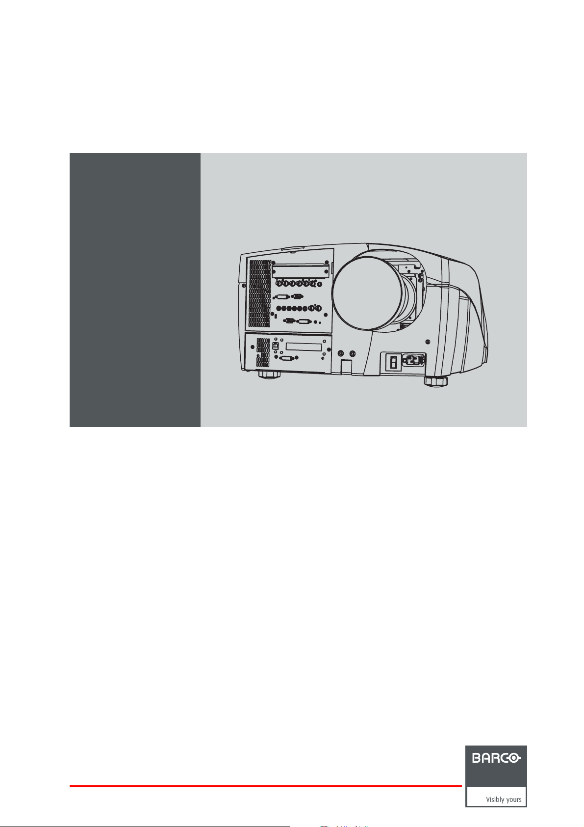
This manual describes the Barco Galaxy NH-12 projector.
It contains 4 main chapters :
1. Installation : The mechanical setup of the projector.
2. Setup : Adjusting the projection parameters in order to get the best image reproduction.
3. Getting started : Start the projector for daily use.
4. Advanced : Advanced operation and setup using the remote control and the projector’s OSD.
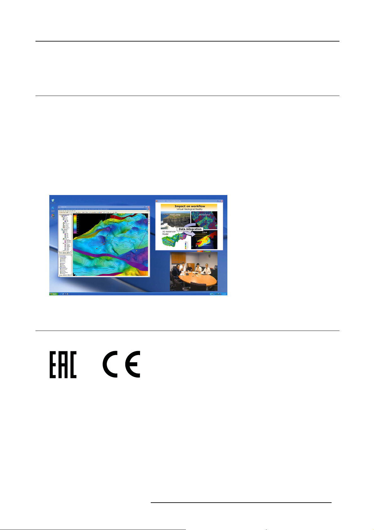
About the Galaxy NH-12
The Barco Galaxy NH-12 is the world’s first active stereoscopic projector with Windows desktop integration that can project 2D
mono and 3D stereo images simultaneously in full native 1080p HD. It is a network-centric projector, which greatly increases its
ease-of-use in image critical and virtual reality applications with large amount of data.
Image 1-1
1.2 Technical Regulations
Certificates
Image 1-2
EAC mark
Image 1-3
CE mark
R59770122 BARCO GALAXY NH-12 20/01/2015 5
Page 10

1. Introduction
6 R59770122 BARCO GALAXY NH-12 20/01/2015
Page 11
2. PACKAGING
N
2.1 Unpacking
CEE7/7
European power plug to connect the power cord to the wall outlet.
NEMA L6-20P
American power plug to connect the power cord to the wall outlet.
Content
• 1 projector (weight ± 70 kg or ± 175 lbs)
• 1 remote control unit RCU + 2 batteries.
• 2 power cables with outlet plug type CEE7 and NEMA L6-20P
•1UserGuide
• 1 Safety manual
• 1 CD-ROM containing the Desktop Integration Software (option)
2. Packaging
Form
The projector is packed in a cardboard box. To provide protection during transportation, the projector is surrounded with foam. The
package is secured with banding and fastening clips.
Lens packaging
The Lens is supplied as an individual item and is packed in a cardboard box.
Save the original shipping cardboard and packing material, they will be necessary if you ever have to transport
the lens.
CAUTION: Never transport the projector with the lens mounted on it !
Always remove the lens before transporting the projector.
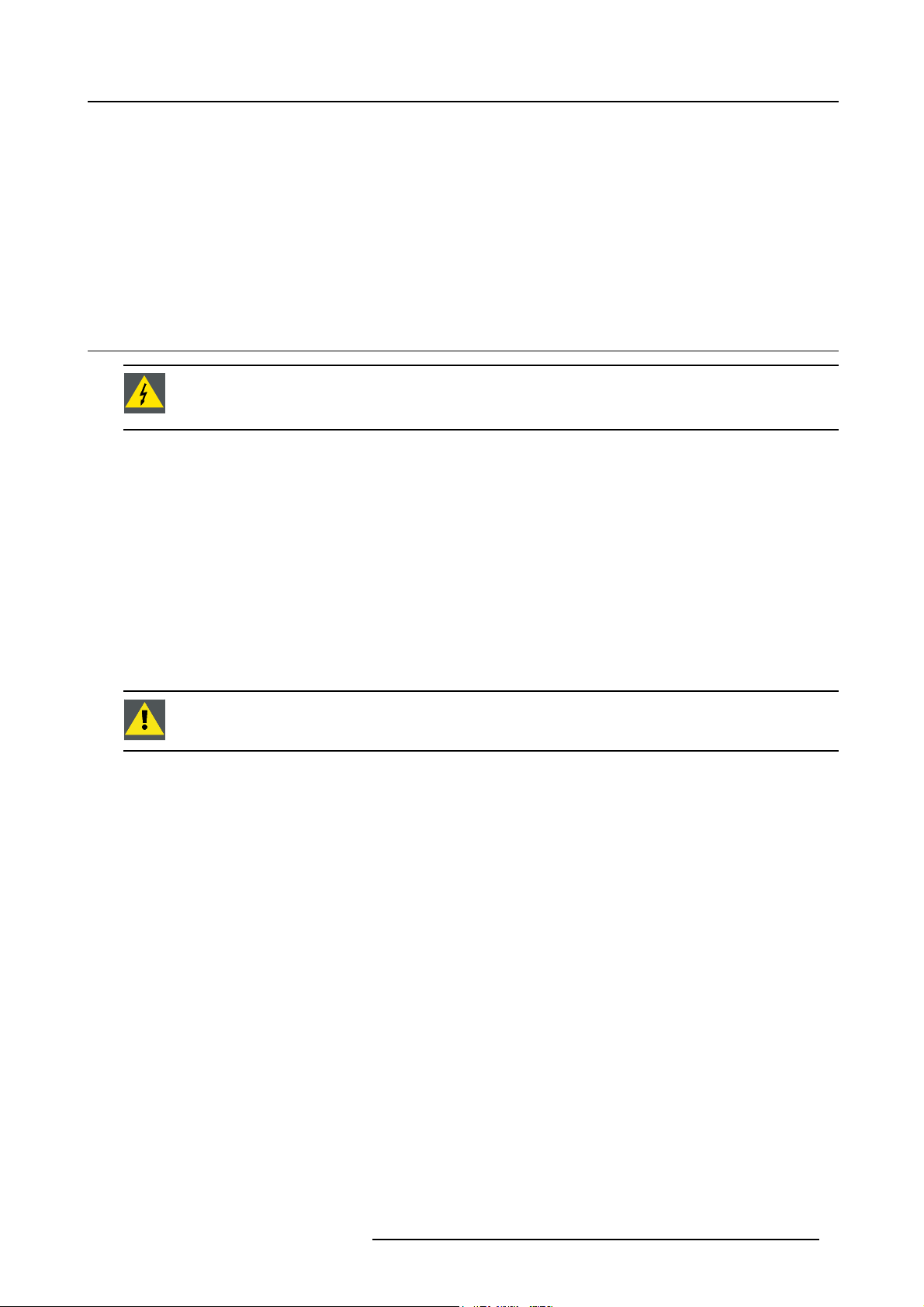
How to unpack the projector ?
1. Release the cord straps.
PULL
TO OPE
Image 2-1
2. Remove the assembly from the pallet
3. Remove the cardboard cover
4. Remove the large cardboard
5. Remove the foam parts
6. Loosen and remove the 3 screws spacers fixing the projector to the wooden board
7. Remove the projector from the board
R59770122 BARCO GALAXY NH-12 20/01/2015
7
Page 12

2. Packaging
Save the original shipping carton and packing material, they will be necessary if you ever have to ship your
projector. For maximum protection, repack your projector as it was originally packed at the factory.
8 R59770122 BARCO GALAXY NH-12 20/01/2015
Page 13
3. Installation guidelines
3. INSTALLATION GUIDELINES
Overview
• General Installation Guidelines
•Airflow guidelines
• Projector position
• Free space
3.1 General Installation Guidelines
WARNING: Before installing the projector, read first the safety instructions in the safety manual (R5976125)
delivered with the projector.
Insure that the projector is installed in an easy to evacuate room in case of a lamp explosion.
Ambient Temperature Conditions.
Careful consideration of things such as image size, ambient light level, projector placement and type of screen to use are critical to
the optimum use of the projection system.
Max. ambient temperature : 35°C or 95°F
Min. ambient temperature : 10°C or 50 °F
The projector will not operate if ambient air temperature is higher than 40°C or 104°F).
Storage temperature: -35°C to +65°C (-31°F to 149°F)
Humidity Conditions
Storage: 0 to 98 % RH Non-condensing
Operation: 0 to 95 % RH Non-condensing
CAUTION: Harmful Environmental Contamination Precaution
Environment
Do not install the projection system in a site near heat sources such as radiators or air ducts, or in a place subject to direct sunlight,
excessive dust or humidity. Be aware that room heat rises to the ceiling; check that temperature near the installation site is not
excessive.
Environment condition check
A projector must always be mounted in a manner which ensures the free flow of clean air into the projectors ventilation inlets. For
installations in environments where the projector is subject to airborne contaminants such as that produced by smoke machines or
similar (these deposit a thin layer of greasy residue upon the projectors internal optics and imaging electronic surfaces, degrading
performance), then it is highly advisable and desirable to have this contamination removed prior to it reaching the projectors clean
air supply. Devices or structures to extract or shield contaminated air well away from the projector are a prerequisite, if this is not a
feasible solution then measures to relocate the projector to a clean air environment should be considered.
Only ever use the manufacturer’s recommended cleaning kit which has been specifically designed for cleaning optical parts, never
use industrial strength cleaners on the projector’s optics as these will degrade optical coatings and damage sensitive optoelectronics
components. Failure to take suitable precautions to protect the projector from the effects of persistent and prolonged air contaminants will culminate in extensive and irreversible ingrained optical damage. At this stage cleaning of the internal optical units will
be non-effective and impracticable. Damage of this nature is under no circumstances covered under the manufacturer’s warranty
and may deem the warranty null and void. In such a case the client shall be held solely responsible for all costs incurred during any
repair. It is the clients responsibility to ensure at all times that the projector is protected from the harmful effects of hostile airborne
particles in the environment of the projector. The manufacturer reserves the right to refuse repair if a projector has been subject to
wantful neglect, abandon or improper use.
Special Care for Laser Beams
Special care should be used when DLP projectors are used in the same room as performant laser equipment. Direct or indirect hitting
of a laser beam on to the lens can severely damage the Digital MicroMirror Devices™ in which case there is a loss of warranty
R59770122 BARCO GALAXY NH-12 20/01/2015
9
Page 14
3. Installation guidelines
Which screen type ?
There are two major categories of screens used for projection equipment. Those used for front projected images and those for rear
projection applications.
Screens are rated by how much light they refl ect (or transmit in the case of rear projection systems) given a determined amount
of light projected toward them. The ‘GAIN’ of a screen is the term used. Front and rear screens are both rated in terms of gain.
The gain of screens range from a white matte screen with a gain of 1 (x1) to a brushed aluminized screen with a gain of 10 (x10)
or more. The choice between higher and lower gain screens is largely a matter of personal preference and another consideration
called the Viewing angle. In considering the type of screen to choose, determine where the viewers will be located and go for the
highest gain screen possible. A high gain screen will provide a brighter picture but reduce the viewing angle. For more information
about screens, contact your local screen supplier.
What image size? How big should the image be?
The projector is designed for projecting an image size : min 1.00m (3.3ft) to max 15 m (49.21ft) (depending on the ambient light
conditions), with the native aspect ratio of the projector.
3.2 Air flow guidelines
What are the air flow guidelines ?
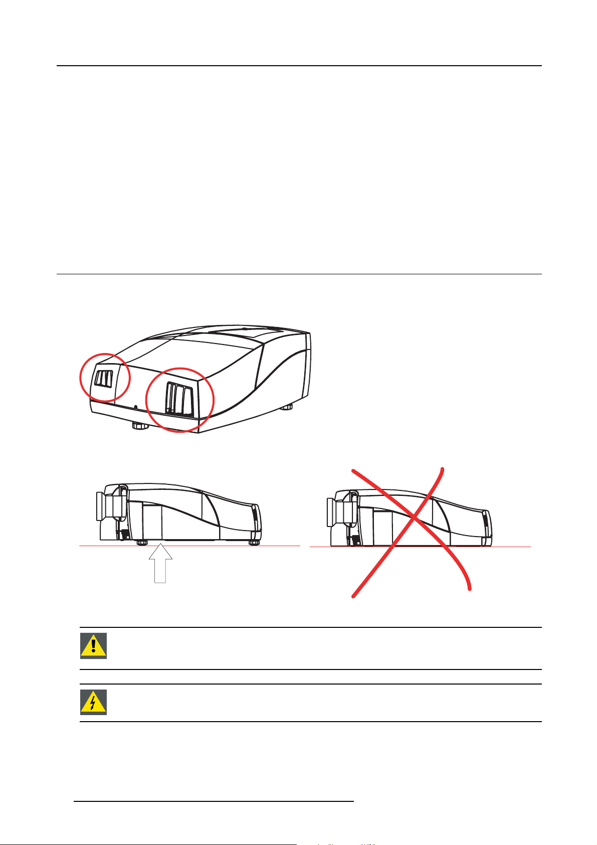
The Air Outlet on the side of the Projector can reach high temperatures due to the High Light Output Range of the lamp.
Image 3-1
Air outlets
Image 3-2
Air inlet obstruction
air intake
CAUTION: Never obstruct the cooling air inlet at the bottom of the projector.
Always insure there is enough space between the bottom of the projector and the floor, to allow air to enter
the projector.
WARNING: Do not touch this Air Outlet when the projector is switched on.
10 R59770122 BARCO GALAXY NH-12 20/01/2015
Page 15
3. Installation guidelines
3.3 Projector position
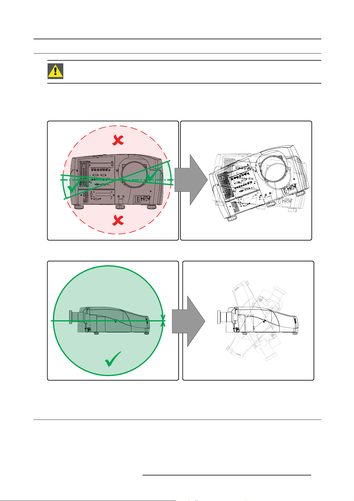
CAUTION: Not respecting the projector tilt range will cause lamp flicker or even premature lamp failure.
Projector tilt range
The tilt range of the projector is restricted by the tilt range of the lamp. The images below show the maximum tilt range in both
senses.
5°
20°
Image 3-3
Projector t ilt ran ge
Image 3-4
Projector t ilt ran ge
3.4 Free space
360°
Service area
Make sure that sufficient free space (area free from obstacles - see the image below) should be available around the projector for
maintenance and service activities.
R59770122 BARCO GALAXY NH-12 20/01/2015
11
Page 16
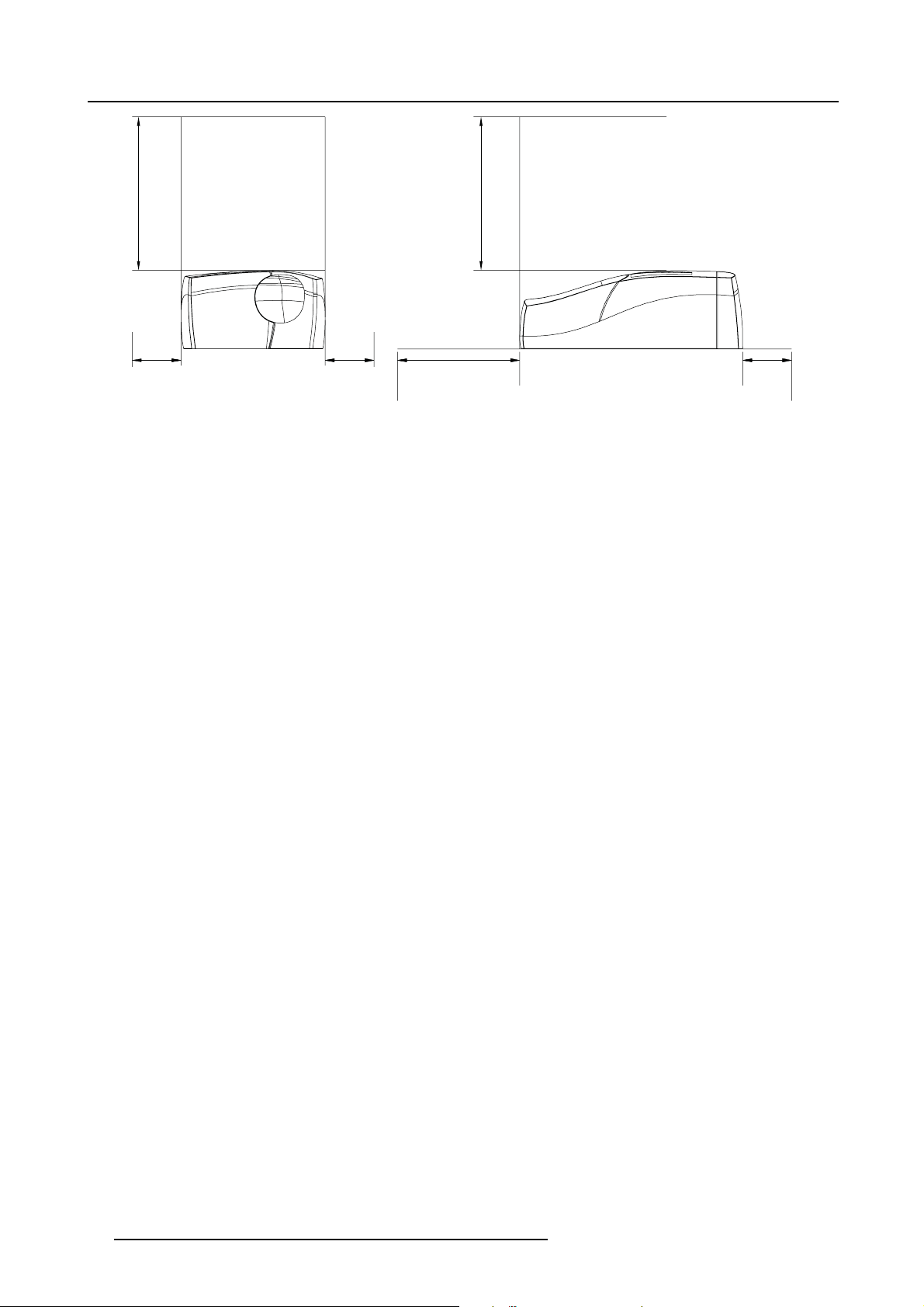
3. Installation guidelines
500 mm
Image 3-5
Dimensions: free space around the projector
500 mm
200 mm200 mm200 mm 500 mm
12 R59770122 BARCO GALAXY NH-12 20/01/2015
Page 17

4. INSTALLATION
Overview
• Battery Installation in the RCU
• Lens installation
• Projector configuration
• Positioning the projector
• Connections
• Controls overview
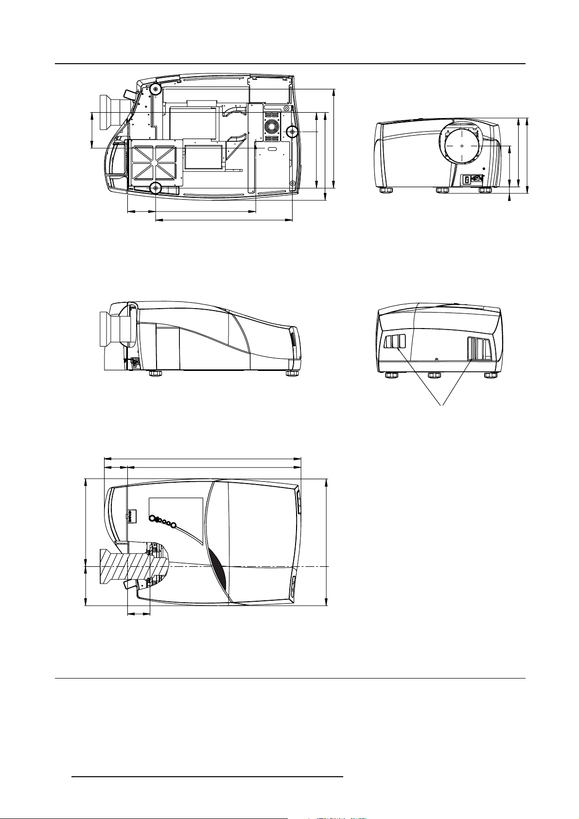
Projector dimensions
Dimensions are given in mm and inch (1inch = 25.4 mm)
weight (without lens) : 70kg (175 lbs)
4. Installation
R59770122 BARCO GALAXY NH-12 20/01/2015
13
Page 18
4. Installation
B
a
r
c
o
i
C
o
n
N
H
-
1
2
166
130
465
635
90
261
408
460
190
30
320
350
108
805
408
589
182
104
913
Image 4-1
Dimensions
4.1 Battery Installation in the RCU
How are the batteries delivered ?
The batteries (not yet installed to save the battery life time) are delivered inside the plastic bag with the power cord.
Air Outlets
How to install
1. Remove the battery cover on the backside of the remote control by pushing the indicated handle a little towards the bottom of
the RCU.
14
R59770122 BARCO GALAXY NH-12 20/01/2015
Page 19
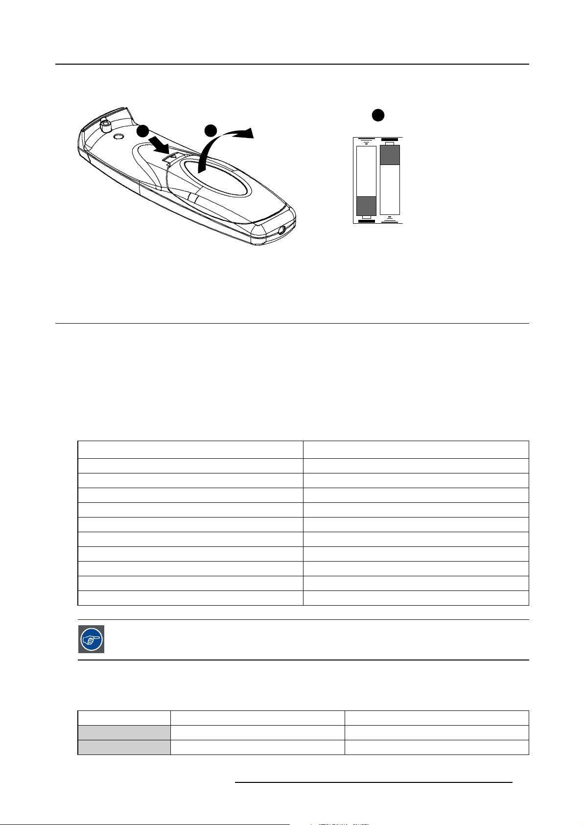
2. Lift up the top side of the cover at the same time.
3. Insert the 2 new 1,5 V batteries as indicated in the RCU.
1
Image 4-2
Battery installation
4. Put the battery cover back on its place.
2
4.2 Lens installation
Overview
4. Installation
3
RCU Top
+
+
• Lens range
• Lens formulas
• Shift capabilities
• Lens installation
4.2.1 Lens range
Overview table
Lens Partnumber
TLD+ (0.73:1)
TLD+ (1.2:1)
TLD+ (1.5–2.0:1)
TLD+ (2.0–2.8:1)
TLD+ (4.5–7.5:1)
TLD HB (0.8:1)
TLD HB (1.6–2.0:1)
TLD HB (2.0–2.8:1)
TLD HB (2.8–5.0:1)
TLD HB (5.0–8.0:1)
See the Maintenance appendix for more information about lens cleaning.
R9842041
R9840775
R9842061
R9842081
R9842121
R9842040
R9842060
R9842080
R9842100
R9842120
4.2.2 Lens formulas
Formulas
Metric Formulas (meter) Inch formulas (inch)
TLD+ (0.73:1) PD = (0.71 x SW) + 0.09 PD = (0.71 x SW) + 3.55
TLD+ (1.2:1) PD = (1.14 x SW) + 0.18 PD = (1.14 x SW) + 7.26
R59770122 BARCO GALAXY NH-12 20/01/2015 15
Page 20
4. Installation
Metric Formulas (meter) Inch formulas (inch)
TLD+ (1.5–2.0:1) PD
TLD+ (2.0–2.8:1) PD
TLD+ 4.5–7.5:1) PD
= (1.42 x SW) + 0.08
min
=(1.88xSW)+0.12
PD
max
= (1.88 x SW) + 0.07
min
=(2.57xSW)+0.07
PD
max
= (4.08 x SW) + 0.07
min
=(6.85xSW)+0.29
PD
max
TLD HB (0.8:1) PD = (0.71 x SW) + 0.04 PD = (0.71 x SW) + 1.6
TLD HB (1.6-2.0:1) PD
TLD HB (2.0-2.8:1) PD
TLD HB (2.8-2.8:1) PD
TLD HB (5.0-8.0:1) PD
= (1.36 x SW) - 0.10
min
= (1.70 x SW) - 0.14
PD
max
= (1.70 x SW) - 0.18
min
= (2.42 x SW) - 0.25
PD
max
= (2.38 x SW) - 0.17
min
PD
= (4.35 x SW) - 0.39
max
= (4.17 x SW) - 0.02
min
= (6.95 x SW) - 0.30
PD
max
The distances are measured starting from the back side of the flange of the projector lens.
PD
= (1.42 x SW) + 3.20
min
= (1.88 x SW) + 4.90
PD
max
PD
= (1.88 x SW) + 2.90
min
= (2.57 x SW) + 2.90
PD
max
PD
= (4.08 x SW) + 2.89
min
= (6.85 x SW) + 11.49
PD
max
PD
=(1.36xSW)-3.9
min
= (1.70 x SW) - 5.5
PD
max
PD
=(1.70xSW)-7.1
min
= (2.42 x SW) - 9.8
PD
max
=(2.38xSW)-6.7
PD
min
PD
= (4.35 x SW) - 15.4
max
PD
=(4.17xSW)-0.8
min
= (6.95 x SW) - 11.8
PD
max
Image 4-3
4.2.3 Shift capabilities
Description
The maximum vertical and horizontal shift range depends on the lens. Shifting outside this range will not guarantee a full image i.e.
some corners of the image will be clipped and will not be visible (will appear dark on the screen).
The table below gives an overview of the shift capabilities in function of the lens :
Lens range
TLD+ (0.73:1) up/down : 35% left/right : 12%
16 R59770122 BARCO GALAXY NH-12 20/01/2015
Vertical shift Horizontal shift
Page 21
4. Installation
B
a
r
c
o
i
C
o
n
N
H
-
1
2
B
a
r
c
o
i
C
o
n
N
H
-
1
2
Lens range
TLD+ (1.2:1)
TLD+ (1.5-2.0:1)
TLD+ (2.0-2.8:1)
TLD+ (2.8-4.5:1)
TLD (4.5-7.5:1)
Ta bl e 4 - 3
Maximum shift range in function of lens
Horizontal Shift in Nominal Position Horizontal Shift : +100%
Projector
Image 4-4
Example of a horizontal shift of 100%
Vertical Shift in Nominal Position
Vertical shift Horizontal shift
up/down : 137% left/right : 57%
Projector
Screen
Screen
Vertical Shift : +100% Vertical Shift : -25%
Projector Projector
Screen
Image 4-5
Example of a vertical shift of +100% and -25%
4.2.4 Lens installation
Necessary tools
Hexagonal key 4 mm (hexagonal) - delivered with the projector
Necessary parts
• Lens
• Lens interface plate (pre-mounted on the lens hol
der)
• 4x M5x12 screws (delivered with the projector and with the lens)
How to install the lens ?
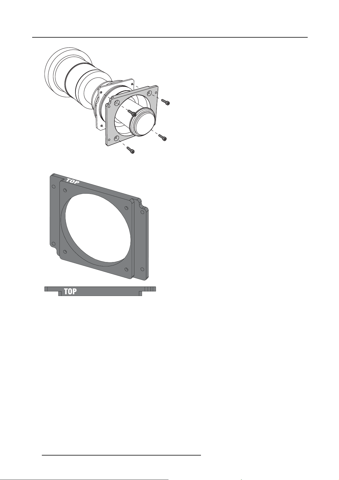
1. Remove the lens interface plate from the lens holder if it is still mounted to it
2. Fix the lens interface plate to the lens using the delivered screws (4)
Note: Install the lens and the lens interface plate with their s creening UP or TOP oriented in the same direction
Caution: Mind the orientation of the lens interface plate in relation to the lens.
Projector
Screen
Screen
R59770122 BARCO GALAXY NH-12 20/01/2015
17
Page 22
4. Installation
UP
Image 4-6
Assembling the lens, screening UP to the top side
Image 4-7
Lens interface plate, screening UP to the top side
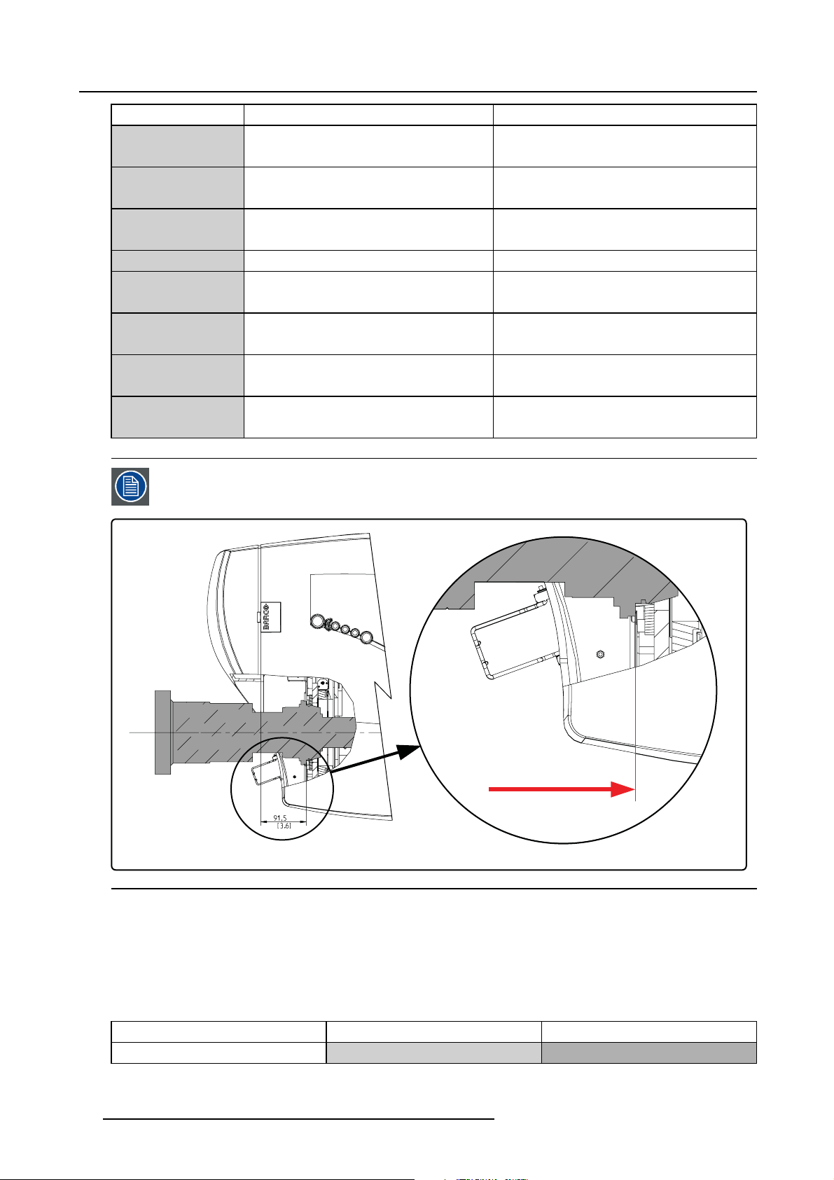
3. Mount the assembly (lens + interface plate) on the lens holder
Insert and tighten the 4 screws with one hand while supporting the lens with the other hand
Caution: Mind the orientation of the lens assem bly: the screenings UP and TOP must be oriented upwards (table c onfigur a-
tion!).
18
R59770122 BARCO GALAXY NH-12 20/01/2015
Page 23
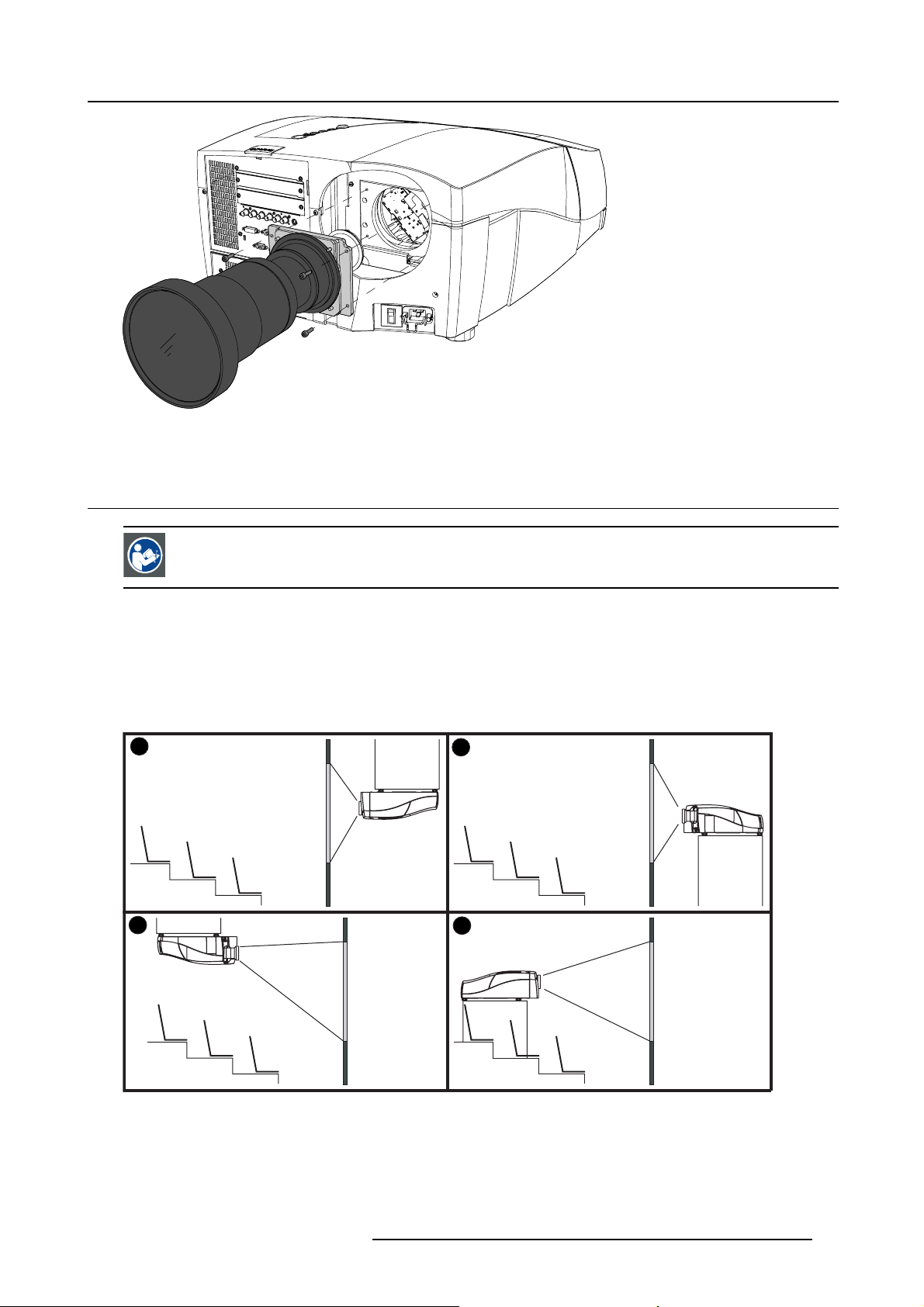
Image 4-8
Lens assembly mounting
4.3 Projector configuration
4. Installation
CAUTION: Projectors in ceiling configuration must have their second pump being connected mechanically
and electrically! If no second pump is present in the projector, the corresponding kit must be installed first.
Contact a Barco trained and certified technician.
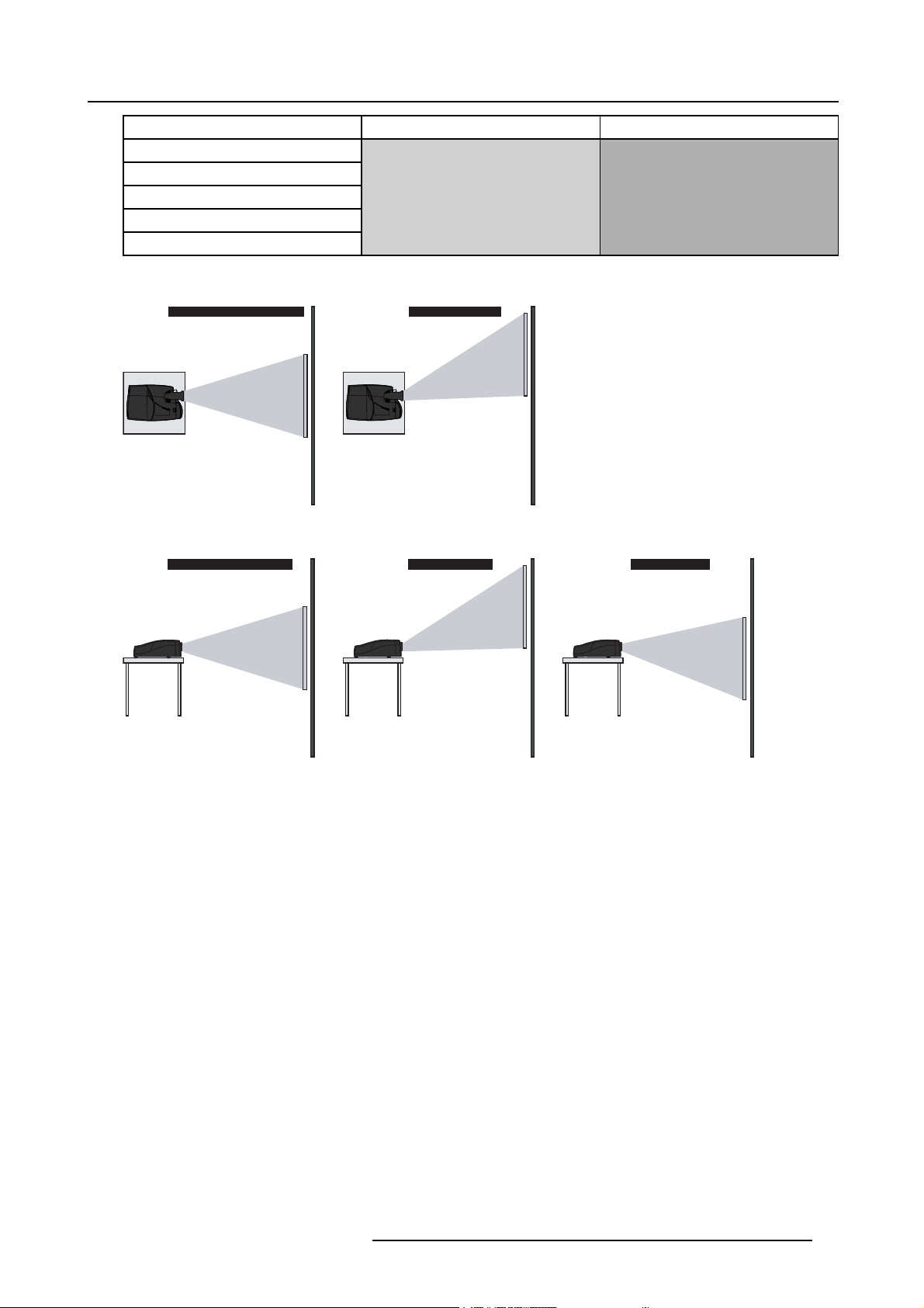
The different configurations
Depending on the installation the projector can be mounted in different ways, the 4 different configurations are:
1. Rear/Ceiling
2. Rear/Table
3. Front/Ceiling
4. Front/Table
1
3
2
4
Image 4-9
Projector configurations
R59770122 BARCO GALAXY NH-12 20/01/2015 19
Page 24
4. Installation
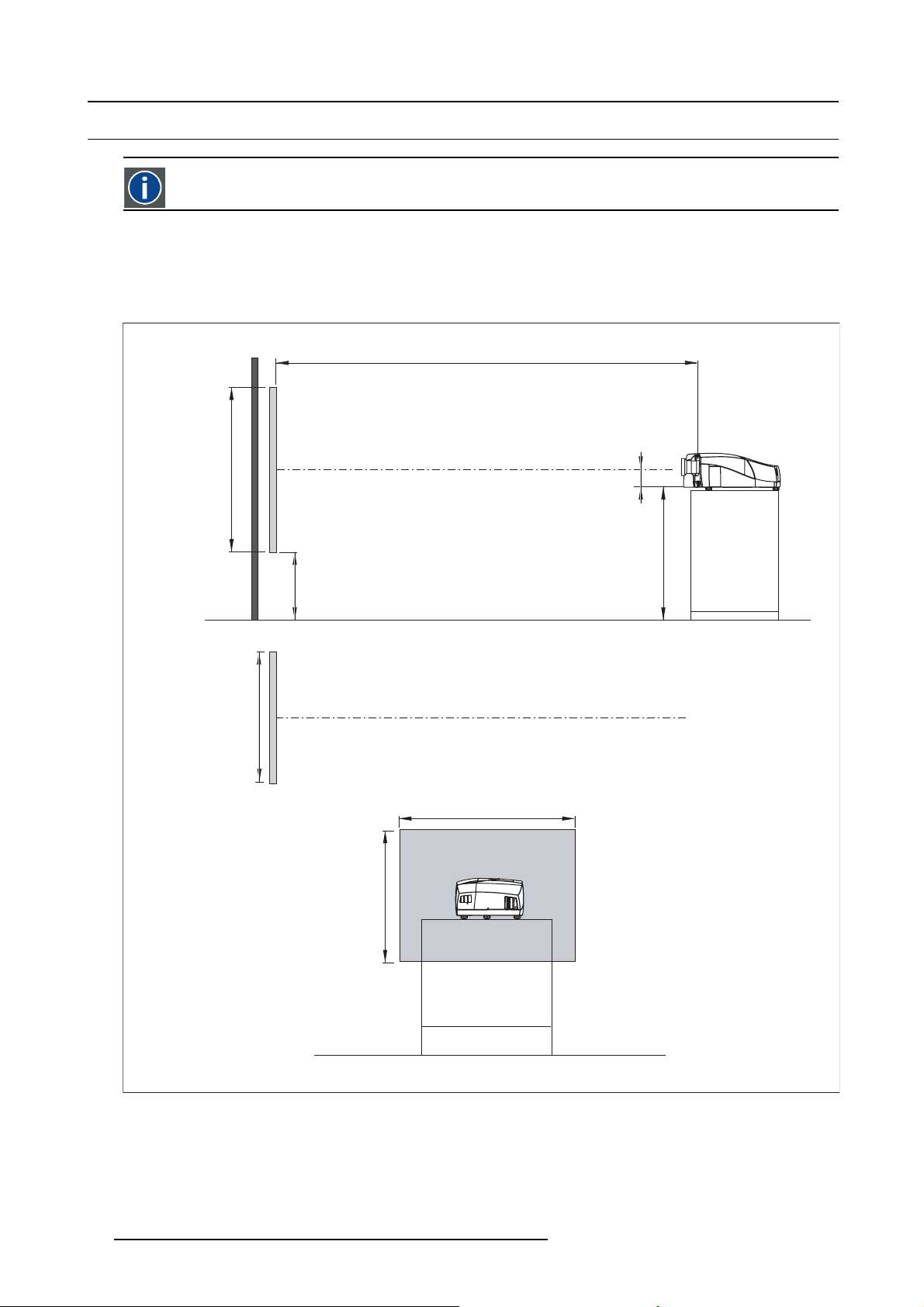
4.4 Positioning the projector
On-Axis projection
Projection where the projector is positioned so as to have the centre of the lens coinciding with the centre of the screen.
Positioning the projector
The position of the projector with reference to the screen may also be different depending on the installation. Basically the projector
can be positioned in an On-Axis or Off-Axis configuration. Several parameters can be calculated determinin
installation.
PD
a
SH
x
A
g the position in any
ref.: Front plate
P
b
c
SW
S
CD=SH/2+B-A
B
F
S
SW
SH
F
Image 4-10
ON-Axis projector installation
aSideview
b Top view
cBackview
x Optical axis projection lens
pProjector
s Screen
FFloor
20 R59770122 BARCO GALAXY NH-12 20/01/2015
Page 25
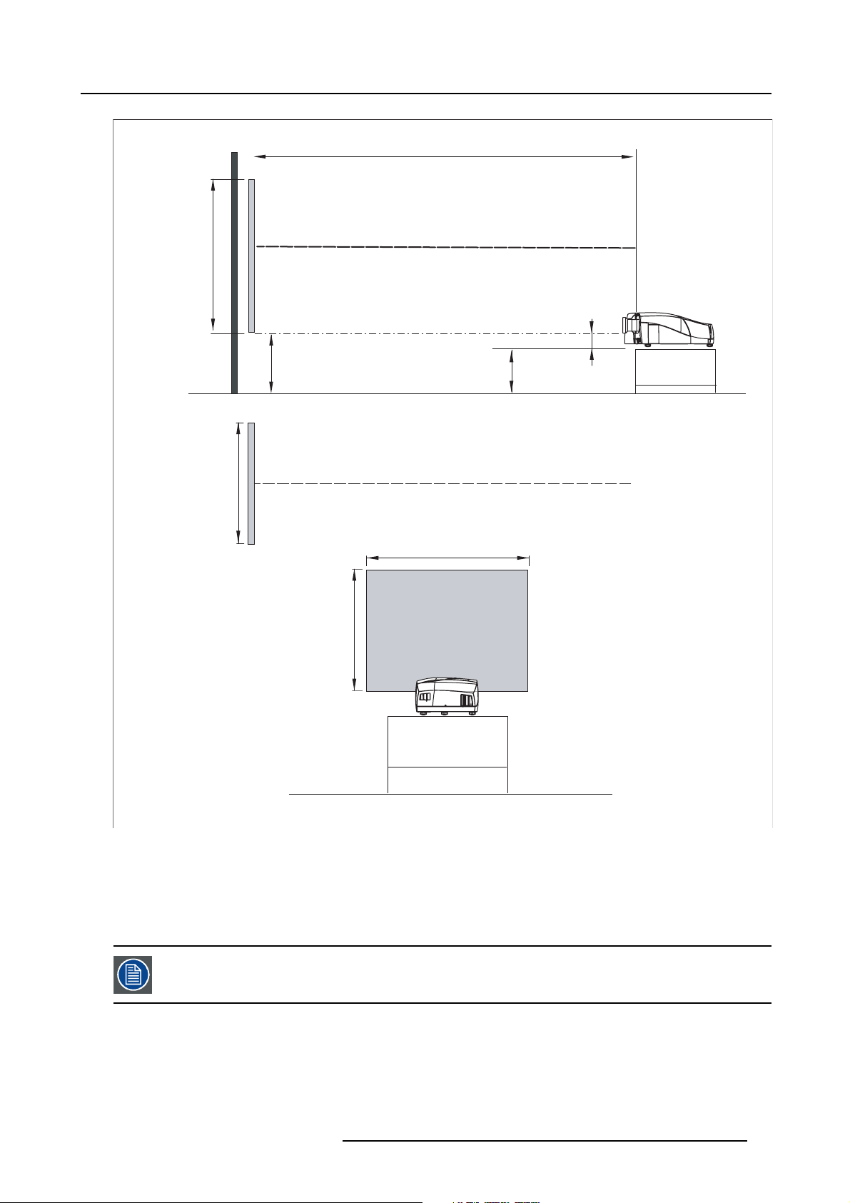
4. Installation
PD
x
a
SH
ref : front plate
P
S
A
B
CD=B-A
F
b
SW
c
Image 4-11
OFF-Axis projector installation
aSideview
b Top view
cBackview
x Optical axis projection lens
pProjector
s Screen
FFloor
S
SW
SH
F
A 100% Off-Axis position means that the position of the centre of the lens is shifted by half the screen height.
R59770122 BARCO GALAXY NH-12 20/01/2015 21
Page 26
4. Installation
4.5 Connections
Overview
• Power connection
• The front panel
• Connecting an RGB signal
• Connecting a component video signal
• Connecting a DVI signal
• Connecting a Composite video signal
• Connecting an S-Video signal
• Connecting a Computer
• Connecting a source to the desktop input
• DVI output
• Stereo connections
•ActiveInfitec
• Communication
• Multichannel Installations
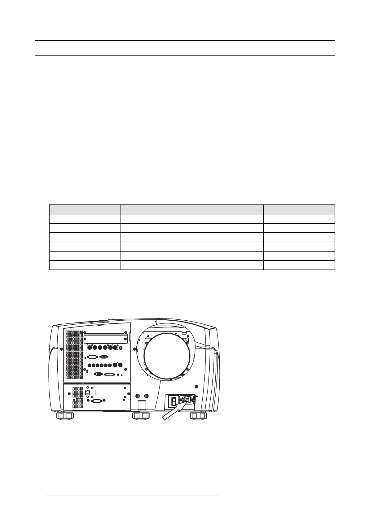
4.5.1 Power connection
Electrical ratings
Projector type Voltage (AC) Current / Power Frequency
NH-12 230V single phase 12 Amps 50-60 Hz
Galaxy NH-12 230V single phase 12 Amps 50-60 Hz
iD LH-12 230V single phase 12 Amps 50-60 Hz
NW-12 220–240V single phase 12 Amps 50-60 Hz
Galaxy NW-12 220–240V single phase 12 Amps 50-60 Hz
Galaxy NW-7 220–240V single phase 12 Amps 50-60 Hz
TM
Power connection
1. Use the supplied power cord to connect the projector to the power outlet.
2. Plug the female power connector into the male connector at the front of the projector, secure the connection with the locking
spring.
Image 4-12
Power connection
22 R59770122 BARCO GALAXY NH-12 20/01/2015
Page 27
4. Installation
DESKTOP INPUT
R / PR
G / Y
B / PB
Hs / Cs
Vs
VIDEO
S-VIDEO
DVI
IN1
IN2
L1
STEREO INPUT
STEREO OUTPUT
L3
IN1
IN2
IN1
IN2
COMPUTER
RS 232 C
DVI
R.C.
OPEN
Image 4-13
Power plug spring system
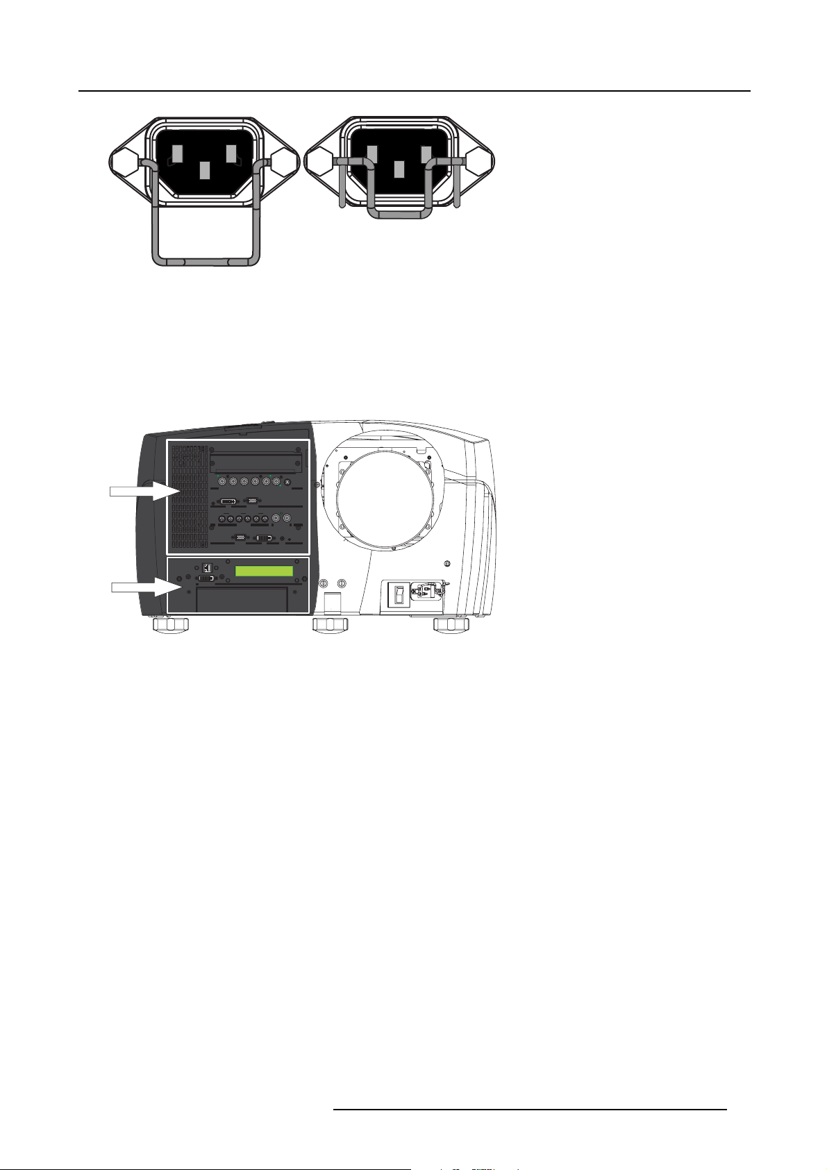
4.5.2 The front panel
View
The front panel of the projector can be divided in 2 major parts :
1. Signal Input/Output section
2. System input/output section
G / Y
Hs / CsVsVIDEO S-VIDEO
R / PR
B / PB
G / Y
Hs / Cs
VIDEO
B / PB
COMPUTER
COMPUTER
IN2
L2 L3
L2L2L3
IN1
Vs
IN2
STEREO OUTPUT
DVI R.C.
DVI
S-VIDEO
R.C.
DESKTOP INPUT
DESKTOP INPUT
R / PR
DVI
DVI
IN1 IN2
IN1 IN2 IN1 IN2
IN1
IN2
IN1
L1
L1
STEREO INPUT STEREO OUTPUT
STEREO INPUT
RS 232 C
RS 232 C
1
2
LOCKED
Image 4-14
Front panel connections
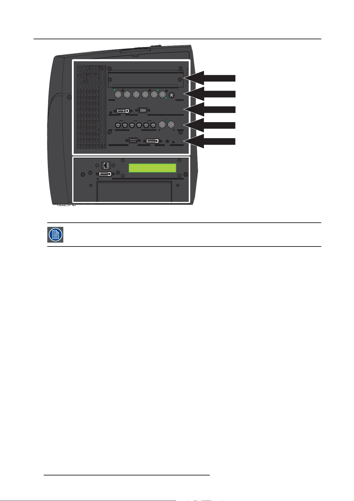
The signal input/output section
The input/output section has a modular architecture i.e. it is composed of several (5) slots which can be equipped with different input
modules :
The different available inputs that can be installed :
• RGBHV, YUV & Video analog input
• twin dual DVI input
• Stereo inputs
• SDI/HDSDI
• DVI (HDCP) / D15
The different available outputs :
• DVI output & RS232 IN
The projector is by default equipped as follows:
• Layer 1: empty (can be fitted with any input board)
• Layer 2: RGB, YUV & Video input board (fixed)
• Layer 3: twin dual DVI input board (fixed)
• Layer 4: Stereo input board (fixed)
• Layer 5: DVI output and RS232 board (fixed)
R59770122 BARCO GALAXY NH-12 20/01/2015
23
Page 28
4. Installation
DESKTOP INPUT
R / PR
G / Y
B / PB
Hs / Cs
Vs
VIDEO
S-VIDEO
DVI
IN1
IN2
L1
STEREO INPUT
STEREO OUTPUT
L2
L3
IN1
IN2
IN1
IN2
COMPUTER
RS 232 C
DVI
R.C.
LAYER1
DESKTOP INPUT
DESKTOP INPUT
Image 4-15
Input/output layers
Layer 2,3,4,5 are fixed i.e. they may only be fitted with the boards mentioned above.
The system section
The bottom system section holds :
G / Y
R / PR
R / PR
B / PB
G / Y
B / PB
DVI
COMPUTER
DVI
IN1 IN2
IN1
L1
L1
COMPUTER
IN1 IN2 IN1 IN2
IN2
IN1
IN2
L2 L3
L2
STEREO INPUT STEREO OUTPUT
STEREO INPUT
RS 232 C
RS 232 C
Hs / Cs
Hs / Cs
IN1
Vs
Vs
IN2
L3
DVI R.C.
DVI
VIDEO S-VIDEO
VIDEO
S-VIDEO
STEREO OUTPUT
R.C.
LAYER2
LAYER3
LAYER4
LAYER5
• Ethernet RJ45 connection
• DVI desktop input
•LCDdisplay
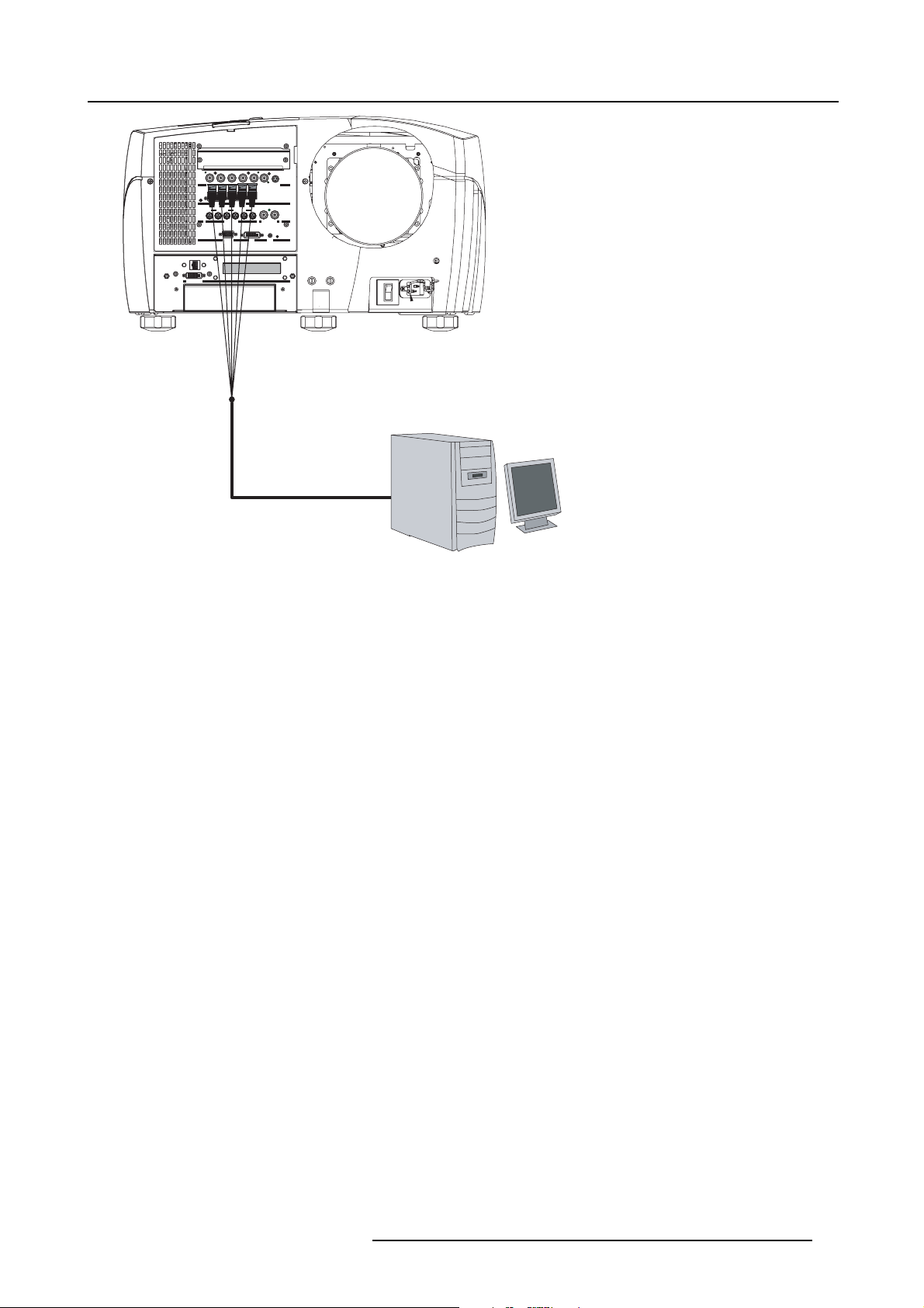
4.5.3 Connecting an RGB signal
How to connect an RGB signal ?
1. Connect the BNC connectors to the projector’s RGB input
24
R59770122 BARCO GALAXY NH-12 20/01/2015
Page 29
DESKTOP INPUT
DESKTOP INPUT
R / PR
G / Y
B / PB
Hs / Cs
Vs
VIDEO
S-VIDEO
DVI
IN1
IN2
L1
STEREO INPUT
STEREO OUTPUT
L3
IN1
IN2
IN1
IN2
COMPUTER
RS 232 C
DVI
R.C.
4. Installation
G / Y
Hs / Cs
VIDEO
B / PB
COMPUTER
IN2
L2L2L3
S-VIDEO
Vs
IN1
IN2
STEREO OUTPUT
DVI
R.C.
R / PR
DVI
IN1
IN2
IN1
L1
STEREO INPUT
RS 232 C
Image 4-16
Connecting an RGB signal
4.5.4 Connecting a component video signal
Introduction
A component video signal can also be mentioned in the following way:
•YUV
•PRYPB
• (R-Y) Y (B-Y)
How to connect a component video signal ?
1. Connect the BNC connectors to the projector’s
PR Y PB input
R59770122 BARCO GALAXY NH-12 20/01/2015
25
Page 30
4. Installation
DESKTOP INPUT
R / PR
G / Y
B / PB
Hs / Cs
Vs
VIDEO
S-VIDEO
DVI
IN1
IN2
L1
STEREO INPUT
STEREO OUTPUT
L3
IN1
IN2
IN1
IN2
COMPUTER
RS 232 C
DVI
R.C.
DESKTOP INPUT
R / PR
G / Y
B / PB
Hs / Cs
Vs
VIDEO
S-VIDEO
DVI
IN1
IN2
L1
STEREO INPUT
STEREO OUTPUT
L3
IN1
IN2
IN1
IN2
COMPUTER
RS 232 C
DVI
R.C.
DESKTOP INPUT
G / Y
Hs / Cs
VIDEO
B / PB
COMPUTER
IN2
L2L2L3
S-VIDEO
Vs
IN1
IN2
STEREO OUTPUT
DVI
R.C.
R / PR
DVI
IN1
IN2
IN1
L1
STEREO INPUT
RS 232 C
Image 4-17
Connecting a YUV signal
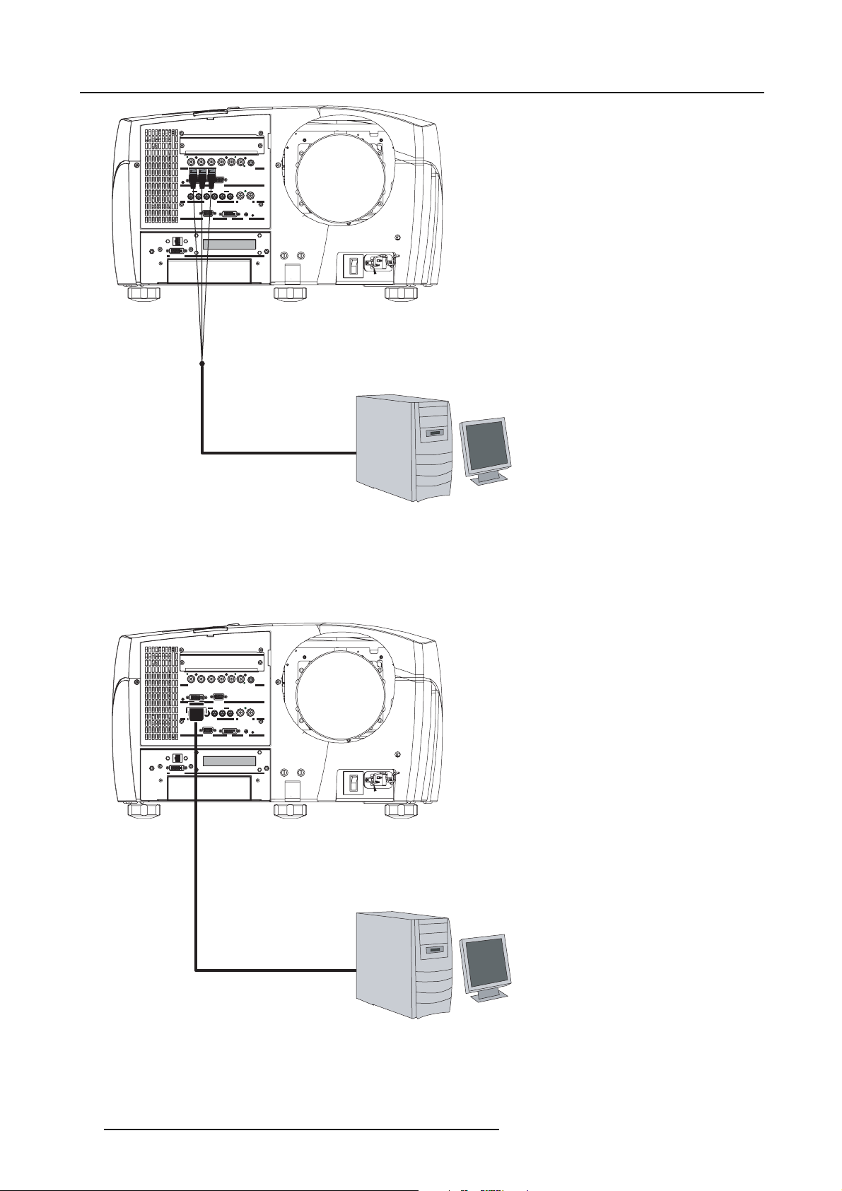
4.5.5 Connecting a DVI signal
How to connect a DVI signal ?
1. Connect the DVI cable to the projector’s DVI input
G / Y
Hs / Cs
VIDEO
B / PB
COMPUTER
IN2
L2L2L3
S-VIDEO
Vs
IN1
IN2
STEREO OUTPUT
DVI
R.C.
R / PR
DVI
IN1
IN2
IN1
L1
STEREO INPUT
RS 232 C
DESKTOP INPUT
Image 4-18
Connecting a DVI signal
26 R59770122 BARCO GALAXY NH-12 20/01/2015
Page 31

4.5.6 Connecting a Composite video signal
DESKTOP INPUT
R / PR
G / Y
B / PB
Hs / Cs
Vs
VIDEO
S-VIDEO
DVI
IN1
IN2
L1
STEREO INPUT
STEREO OUTPUT
L3
IN1
IN2
IN1
IN2
COMPUTER
RS 232 C
DVI
R.C.
DESKTOP INPUT
R / PR
G / Y
B / PB
Hs / Cs
Vs
VIDEO
S-VIDEO
DVI
IN1
IN2
L1
STEREO INPUT
STEREO OUTPUT
L3
IN1
IN2
IN1
IN2
COMPUTER
RS 232 C
DVI
R.C.
How to connect a composite video signal ?
1. Connect the BNC connector to the projector’s video input
G / Y
Hs / Cs
VIDEO
B / PB
COMPUTER
IN2
L2L2L3
S-VIDEO
Vs
IN1
IN2
STEREO OUTPUT
DVI
R.C.
DESKTOP INPUT
R / PR
DVI
IN1
IN2
IN1
L1
STEREO INPUT
RS 232 C
4. Installation
POWER
Image 4-19
Connecting a composite video signal
4.5.7 Connecting an S-Video signal
How to connect an S-Video signal ?
1. Connect the mini DIN connector to the projector’s S-Video input
G / Y
Hs / Cs
VIDEO
B / PB
COMPUTER
IN2
L2L2L3
S-VIDEO
Vs
IN1
IN2
STEREO OUTPUT
DVI
R.C.
DESKTOP INPUT
R / PR
DVI
IN1
IN2
IN1
L1
STEREO INPUT
RS 232 C
VHS
RECORD
RECORD
Image 4-20
Connecting an S-Video signal
POWER
VHS
4.5.8 Connecting a Computer
How to connect a computer ?
1. Connect the D15 connector to the projector’s computer input
R59770122 BARCO GALAXY NH-12 20/01/2015 27
Page 32

4. Installation
DESKTOP INPUT
R / PR
G / Y
B / PB
Hs / Cs
Vs
VIDEO
S-VIDEO
DVI
IN1
IN2
L1
STEREO INPUT
STEREO OUTPUT
L3
IN1
IN2
IN1
IN2
COMPUTER
RS 232 C
DVI
R.C.
DESKTOP INPUT
R / PR
G / Y
B / PB
Hs / Cs
Vs
VIDEO
S-VIDEO
DVI
IN1
IN2
L1
STEREO INPUT
STEREO OUTPUT
L3
IN1
IN2
IN1
IN2
COMPUTER
RS 232 C
DVI
R.C.
DESKTOP INPUT
G / Y
Hs / Cs
VIDEO
B / PB
COMPUTER
IN2
L2L2L3
S-VIDEO
Vs
IN1
IN2
STEREO OUTPUT
DVI
R.C.
R / PR
DVI
IN1
IN2
IN1
L1
STEREO INPUT
RS 232 C
Image 4-21
Connecting a computer
4.5.9 Connecting a source to the desktop input
How to connect a desktop source to the desktop input ?
1. Connect the source to the desktop input connection (DVI connector)
G / Y
Hs / Cs
VIDEO
B / PB
COMPUTER
IN2
L2L2L3
S-VIDEO
Vs
IN1
IN2
STEREO OUTPUT
DVI
R.C.
R / PR
DVI
IN1
IN2
IN1
L1
STEREO INPUT
RS 232 C
DESKTOP INPUT
Image 4-22
Connecting a desktop input
Tip: An Ethernet connection must also be set to allow Desktop integration
28
R59770122 BARCO GALAXY NH-12 20/01/2015
Page 33

The projector can be connected to a LAN or can be connected to a desktop PC via a crossed cable (as indicated
DESKTOP INPUT
R / PR
G / Y
B / PB
Hs / Cs
Vs
VIDEO
S-VIDEO
DVI
IN1
IN2
L1
STEREO INPUT
STEREO OUTPUT
L3
IN1
IN2
IN1
IN2
COMPUTER
RS 232 C
DVI
R.C.
above).
The desktop can be enabled/disabled, "Desktop", page 125
Using the desktop input makes only sense when using the Barco Desktop integration software. The Desktop
integration software is covered in the Desktop integration User Guide.
4.5.10 DVI output
DVI output
R / PR
IN1
L1
4. Installation
G / Y
Hs / Cs
VIDEO
S-VIDEO
B / PB
Vs
DVI
COMPUTER
IN2
IN1
IN2
IN1
IN2
L2L2L3
STEREO INPUT
STEREO OUTPUT
DVI
R.C.
RS 232 C
DESKTOP INPUT
Image 4-23
DVI output
The DVI output is a single link DVI output signal, having the following specifications:
• resolution: is the same as the native resolution of the projector;
• vertical refresh rate: 60 Hz;
• signal type: digital signal (DVI).
It reflects the projected image, excluding Geometry corrections, Soft edge and Black level correction, Dynacolor settings and OSD.
CAUTION: If the projector runs in synchronous mode, the DVI output is synchronous with the input signal.
In this mode, most monitors will not display the signal in a correct way!
CAUTION: If the selected input signal is a stereo signal, a black image is displayed at the DVI output.
4.5.11 Stereo connections
What can be done ?
The stereo sources sync signals have to be connected to the 4th layer of the front panel. The stereo input layer holds 6 mini DIN
connectors and 2 BNC connectors.
The 6 mini DIN connectors are the stereo sync input connections for respectively from the left to the right, the 1
The order is from left to right eg. for the DVI input board, the left DIN connector (L3/IN1) is for the left connector on the DVI input
board and the right DIN connector (L3/IN2) is for the right connector on the DVI input board.
st,2nd
and 3rdlayer.
R59770122 BARCO GALAXY NH-12 20/01/2015
29
Page 34

4. Installation
R / PR
G / Y
B / PB
Hs / Cs
Vs
VIDEO
S-VIDEO
DVI
IN1
IN2
L1
STEREO INPUT
STEREO OUTPUT
L3
IN1
IN2
IN1
IN2
COMPUTER
RS 232 C
DVI
R.C.
DESKTOP INPUT
R / PR
G / Y
B / PB
Hs / Cs
Vs
VIDEO
S-VIDEO
DVI
IN1
IN2
L1
STEREO INPUT
STEREO OUTPUT
L3
IN1
IN2
IN1
IN2
COMPUTER
RS 232 C
DVI
R.C.
r
G / Y
R / PR
R / PR
IN1 IN2
IN1
L1
Image 4-24
Stereo input connections
The BNC connectors are the stereo output sync signals. These signals will drive the emitters in case of active stereo projection
using active stereo glasses. The fact that the projector is providing two BNC is to allow the linking (stereo synchronization) of several
projectors in a multichannel projection system (see Multichannel installation).
The 2 BNC’s are identical i.e. it does not matter to which BNC the emitter is connected.
Hs / CsVsVIDEO S-VIDEO
B / PB
G / Y
Hs / Cs
B / PB
DVI
COMPUTER
DVI
COMPUTER
IN1 IN2 IN1 IN2
IN2
IN1
IN2
IN1
L2 L3
L1
L2L2L3
STEREO INPUT STEREO OUTPUT
STEREO INPUT
RS 232 C
RS 232 C
VIDEO
Vs
IN2
STEREO OUTPUT
DVI R.C.
DVI
S-VIDEO
R.C.
How to connect the stereo input and output signals ?
1. Connect the mini-din male connector(s) to the projector’s female mini DIN connector(s)
G / Y
Hs / Cs
VIDEO
B / PB
COMPUTER
IN2
L2L2L3
S-VIDEO
Vs
IN1
IN2
STEREO OUTPUT
DVI
R.C.
Image Generator
Image Generator
R / PR
DVI
IN1
IN2
IN1
L1
STEREO INPUT
RS 232 C
DESKTOP INPUT
IR Emitter
IR Emitte
Active Glasses
Image 4-25
Image Generator
2. Connect the BNC connector to the stereo IR emitter
Stereo settings
Different stereo settings have to be done :
30
R59770122 BARCO GALAXY NH-12 20/01/2015
Page 35

4. Installation
DESKTOP INPUT
R / PR
G / Y
B / PB
Hs / Cs
Vs
VIDEO
IN1
IN2
L1
STEREO INPUT
L2L3L3
IN1
IN2
IN1
RS 232 C
DVI
R.C.
VIDEO
•stereoinput settings in the Image menu : to match the Image generator to the projector. "Input stereo sync", page 75
•stereooutput & system settings in the Display setup menu : to match the projector to the emitters ,..."Stereo System Setup",
page 146
•stereodisplay settings in the Display setup menu : to decide how to display the video content. "Stereo display settings", page
126
Stereo input settings
G / Y
Hs / CsVsVIDEO
IN2
L2 L3
L2
S-VIDEO
Hs / Cs
VIDEO
S-VIDEO
Vs
IN1
STEREO OUTPUT
DVI R.C.
DVI
R.C.
Stereo Display settings
5
Image Generator
R / PR
B / PB
G / Y
R / PR
B / PB
IN1 IN2
IN1 IN2 IN1
IN2
IN1
IN1
L1
L1
STEREO INPUT STEREO OUTPUT
STEREO INPUT
RS 232 C
RS 232 C
Stereo Output & System settings
DESKTOP INPUT
DESKTOP INPUT
IR Emitter
IR Emitter
Active Glasses
Image 4-26
Stereo settings
See the Display setup menu (for the stereo output and system settings) and the Image menu (for the stereo
input settings)
4.5.12 Active Infitec
TM
TheActiveInfitecTMfeature is optional: a software key is needed to activate it.
How to connect when using active InfitecTMs
1. The input connection is done in the same way as described above but the stereo output signal is not required in this case since
Infitec
TM
stereo glasses are required instead (these glasses are passive i.e. not switched).
tereo ?
4.5.13 Communication
Overview
• Network connections
• Network settings
• RS232 communication
4.5.13.1 Network connections
What can be done ?
The projector can be connected to a network allowing it to be accessed from any connected network device. The Ethernet connection
can be used to upload/download projector software and/or to set up communication (TCP-packets) with the projector. This network
can be a local area network or a small dedicated network
R59770122 BARCO GALAXY NH-12 20/01/2015
31
Page 36

4. Installation
DESKTOP INPUT
R / PR
G / Y
B / PB
Hs / Cs
Vs
VIDEO
S-VIDEO
DVI
IN1
IN2
L1
STEREO INPUT
STEREO OUTPUT
L3
IN1
IN2
IN1
IN2
COMPUTER
RS 232 C
DVI
R.C.
Following operations are made possible :
• file transfer for firmware upgrade
• easy adjustment of projector
• storage of multiple projector configurations and set ups.
• wide range of control possibilities.
• linking the projectors to allow uniform color (Linked Dynacolor) and brightness (CLO) ,...
•...
The connection to the projector can be done via a crossed cable or via a HUB on the local network (LAN).
The Ethernet connection is also used to allow the Desktop integration. The software on the delivered CDROM
must therefore be installed on the desktop PC. See the Desktop integration software User Guide.
How to connect the projector ?
1. Connect the RJ 45 male plug to the projector’s RJ 45 female connector
G / Y
Hs / Cs
VIDEO
IN1
STEREO INPUT
RS 232 C
B / PB
COMPUTER
IN2
L2L2L3
S-VIDEO
Vs
IN1
IN2
STEREO OUTPUT
DVI
R.C.
R / PR
DVI
IN1
IN2
L1
Image 4-27
Crossed cable connection
DESKTOP INPUT
32 R59770122 BARCO GALAXY NH-12 20/01/2015
Page 37

DESKTOP INPUT
R / PR
G / Y
B / PB
Hs / Cs
Vs
VIDEO
S-VIDEO
DVI
IN1
IN2
L1
STEREO INPUT
STEREO OUTPUT
L3
IN1
IN2
IN1
IN2
COMPUTER
RS 232 C
DVI
R.C.
HUB
DESKTOP INPUT
4. Installation
G / Y
Hs / Cs
VIDEO
B / PB
COMPUTER
IN2
L2L2L3
S-VIDEO
Vs
IN1
IN2
STEREO OUTPUT
DVI
R.C.
R / PR
DVI
IN1
IN2
IN1
L1
STEREO INPUT
RS 232 C
Image 4-28
Connection via a hub
See Network settings to set the communication port.
The linking of projectors is treated in the section “Setup of the linked projectors in a multichannel system”
4.5.13.2 Network settings
CAUTION: Make sure that a DHCP server is available in the network and works fine.
In normal conditions, the network detection takes few seconds. This means that the total time needed to go
from power ON to Standby mode is only a few seconds. This value can vary depending on the speed of the
network connection.
But when the DHCP setting of the projector is set to Yes and the network does not allow the projector to obtain
an IP address from the DHCP server, the startup time will be delayed by upto five minutes. After this time, a
time-out occurs if the network detection fails, and the projector starts up without any network connection.
To LAN
What can be done?
These settings are used to set the Ethernet Communication parameters.
R59770122 BARCO GALAXY NH-12 20/01/2015
33
Page 38

4. Installation
Following parameters are available :
MAC Address MAC Address of the projector (This is a non-adjustable value programmed into the Ethernet
IP Address (Current) IP Address of the projector (This is a non-adjustable value).
Subnet Mask Subnet Mask (This is a non-adjustable value)
Gateway Gateway (This is a non-adjustable value)
DHCP
IP Address
Subnet Mask Subnet Mask : this field can be edited when Fixed IP is selected
Gateway Gateway : this field can be edited when Fixed IP is selected
Hostname
board).
DHCP setting:
• Yes: The projector will dynamically obtain its IP address from the DHCP server.
• No: The IP address needs to be entered manually. Note that when selecting Fixed IP
the IP settings fields are enabled
Fixed IP Address of the projector : this field can be edited when Fixed IP is selected
Hostname : this field can be edited when DHCP is selected
How to set up the network settings ?
1. Press the MENU key to activate the Menu bar.
2. Push the cursor key ← or → to highlight Installation in the menu bar.
3. Push the ↓ keytopulldowntheInstallation menu.
4. Push the cursor key ↑ or ↓ to highlight Network settings and press ENTER to select.
34
Image 4-29
A dialog box will be displayed.
R59770122 BARCO GALAXY NH-12 20/01/2015
Page 39

4. Installation
Image 4-30
5. Push the cursor key ↑ or ↓ to highlight the desired parameter.
6. Use the cursor key ← or → , the numeric keys on the RCU, or the local keypad, to edit and change the values.
7. Press Apply settings to apply the changes
A dialog box is shown. The different executed operations are shown with a checkbox. The last operation Restarting network
takes a few seconds more.
Image 4-31
4.5.13.3 RS232 communication
What is possible with the RS232 connection ?
1. Remote control :
2. Data communications: sending data to the projector or copying the data from the projector to a memory device (hard disc,
floppy, etc.).
How to connect the RS232 ports?
1. Connect the D9 connector from the RS232 cable to the RS Input on the projector.
R59770122 BARCO GALAXY NH-12 20/01/2015
35
Page 40

4. Installation
DESKTOP INPUT
R / PR
G / Y
B / PB
Hs / Cs
Vs
VIDEO
S-VIDEO
DVI
IN1
IN2
L1
STEREO INPUT
STEREO OUTPUT
L3
IN1
IN2
IN1
IN2
COMPUTER
RS 232 C
DVI
R.C.
Image 4-32
RS232 connection
DESKTOP INPUT
G / Y
Hs / Cs
VIDEO
B / PB
COMPUTER
IN2
L2L2L3
S-VIDEO
Vs
IN1
IN2
STEREO OUTPUT
DVI
R.C.
R / PR
DVI
IN1
IN2
IN1
L1
STEREO INPUT
RS 232 C
4.5.14 Multichannel Installations
Overview
•LinkedCLO
• Linked Dynacolor
•Linkedstereo
4.5.14.1 Linked CLO
Linking CLO in a multichannel system
The linking of the projectors to allow CLO and Dynacolor information interchange is done via the Ethernet connection.
To set the projector as Master see “Setup of the linked projectors in a multichannel system”.
36
R59770122 BARCO GALAXY NH-12 20/01/2015
Page 41

DESKTOP INPUT
G / Y
R / PR
B / PB
DVI
IN1 IN2
IN1 IN2 IN1 IN2
L1
L2 L3
STEREO INPUT STEREO OUTPUT
RS 232 C
G / Y
R / PR
B / PB
DVI
IN1 IN2
IN1 IN2 IN1 IN2
L1
L2 L3
STEREO INPUT STEREO OUTPUT
RS 232 C
4. Installation
Hs / CsVsVIDEO S-VIDEO
COMPUTER
DVI R.C.
Switch
Hs / CsVsVIDEO S-VIDEO
COMPUTER
DVI R.C.
DESKTOP INPUT
G / Y
Hs / CsVsVIDEO S-VIDEO
R / PR
B / PB
DVI
COMPUTER
IN1 IN2
IN1 IN2 IN1 IN2
L1
L2 L3
STEREO INPUT STEREO OUTPUT
DVI R.C.
RS 232 C
DESKTOP INPUT
Image 4-33
4.5.14.2 Linked Dynacolor
Linking Dynacolor in a multichannel system
The linking of the projectors to allow Dynacolor and CLO information interchange is done via the Ethernet connection.
To set the projector as Master see “Setup of the linked projectors in a multichannel system”.
4.5.14.3 Linked stereo
Linking stereo in a multichannel system
The genlocking for stereo is done using a coax link.
The projectors are connected in a daisy chain. Only the output side may drive IR-emitters.
R59770122 BARCO GALAXY NH-12 20/01/2015
37
Page 42

4. Installation
Image Generator
G / Y
Hs / CsVsVIDEO S-VIDEO
R / PR
B / PB
DVI
COMPUTER
IN1 IN2
IN1 IN2 IN1 IN2
L1
L2 L3
STEREO INPUT STEREO OUTPUT
DVI R.C.
RS 232 C
DESKTOP INPUT
G / Y
Hs / CsVsVIDEO S-VIDEO
R / PR
B / PB
DVI
COMPUTER
IN1 IN2
IN1 IN2 IN1 IN2
L1
L2 L3
STEREO INPUT STEREO OUTPUT
DVI R.C.
RS 232 C
DESKTOP INPUT
Image 4-34
Connections : linked stereo
The stereo out sync signal available on the BNC output can be disabled, see “Stereo Sync out” in the installation menu.
R / PR
IN1 IN2
DESKTOP INPUT
IR Emitter
G / Y
B / PB
DVI
COMPUTER
IN1 IN2 IN1 IN2
L1
L2 L3
STEREO INPUT STEREO OUTPUT
RS 232 C
Hs / CsVsVIDEO S-VIDEO
DVI R.C.
IR Emitter
CadWall
Active Glasses
38 R59770122 BARCO GALAXY NH-12 20/01/2015
Page 43

4.6 Controls overview
F1
F2
F3
MENU
BACK
ENTER
PAUSE
AUTO IMAGE
PC
RGB
VIDEO
Fire Wire
DVI
IQ-PC
SDI
S-VIDEO
PHASE
PIP
TINT
COLOR
BRIGHTN
CONTR
FOCUS
LENS
ZOOM
LENS
ZOOM
DIGI
SHIFT
LENS
VOL
9
0
7
8
5
6
3 4
1
2
RCU
4. Installation
1
2
3
MENU
4
5
6
7
8
9
10
Image 4-35
Remote Control Unit
SDI
DVI
VIDEO
RGB
F1
PAUSE
AUTO IMAGE
IQ-PC
Fire Wire
S-VIDEO
LENS
ZOOM
LENS
FOCUS
F2
F3
BACK
ENTER
PIP
*
DIGI
ZOOM
PHASE
TINT
COLOR
BRIGHTN
PC
CONTR
LENS
SHIFT
VOL
19
18
17
16
15
14
13
12
11
16
Image 4-36
Local keypad
S
N
LE
CE
R
U
SO
6
18
17
The following table gives an overview of the different functionalities of the keys that can be found on the RCU:
1 Function keys Not used
2 MENU Menu key, to enter or exit the Tool bar menu
3 Address key
(Recessed key), to enter the address of the projector (between 0 and 9). Press the recessed
address key with a pencil, followed by pressing one digit button between 0 and 9
4 LOGO Cycle through Focus and Convergence internal patterns
5
PAUSE To stop projection for a short time, press ’PAUSE’. The image disappears but full power is
retained for immediate restarting.
6
STANDBY Standby button, to start projector when the power switch is switched on and to switch off the
projector without switching off the power switch
Attention: Switching to Standby. When the projector is running and you want to go to
standby, press the standby key for 2 seconds.
7
MUTE Not used
8 Auto image Not used
9 Digit buttons Direct input selection
10 Lens control Use these button to obtain the desired ZOOM, SHIFT, FOCUS
11 VOL Not used
12 Picture Controls Use these buttons to obtain the desired picture analog level
13 DIGI ZOOM Not used
14 FREEZ Not used
15 PIP Not used
16 ENTER To confirm an adjustment or selection in the menu
17 Cursor keys To make menu selections, to perform bare scale adjustments or to zoom/focus when the direct
18
R59770122 BARCO GALAXY NH-12 20/01/2015 39
BACK To leave the selected menu or item (go upwards to previous menu)
19
RCU operation
indication led
access is active
Lights up when a button on the remote control is pressed. (This is a visual indicator to check
the operation of the remote control)
Page 44

4. Installation
The LCD display
The LCD display on the bottom of the front panel allows to inform the user on the status of the projector and other information like
warnings etc.
Galaxy NH-12 standby
DESKTOP INPUT
Image 4-37
LCD Display
See the Appendix for a listing of the existing error messages.
40 R59770122 BARCO GALAXY NH-12 20/01/2015
Page 45

5. SETUP
DESKTOP INPUT
R / PR
G / Y
B / PB
Hs / Cs
Vs
VIDEO
S-VIDEO
DVI
IN1
IN2
L1
STEREO INPUT
STEREO OUTPUT
L3
IN1
IN2
IN1
IN2
COMPUTER
RS 232 C
DVI
R.C.
Overview
• Powering up the projector
• Starting up the projector
• Setting up the Remote Control Unit address
• Setting up the projector address (only if necessary)
• Setting up the orientation
• Adjusting the lens
• Setup the baud rate for serial communication
• Preferences
• Setup of the Linked projectors in a Multichannel system
5.1 Powering up the projector
How to power up the projector ?
1. Switch the power switch to “1”
5. Setup
G / Y
Hs / Cs
VIDEO
B / PB
COMPUTER
IN2
L2L2L3
S-VIDEO
Vs
IN1
IN2
STEREO OUTPUT
DVI
R.C.
1
0
Image 5-1
Power switch
DESKTOP INPUT
R / PR
DVI
IN1
IN2
IN1
L1
STEREO INPUT
RS 232 C
2. The software will be initialized. This may take up to 30 seconds. During this phase the LCD display is lit (1). The initialization is
followed by the keypad lighting up briefly (5 seconds) and the projector Standby status (2) .
1
Galaxy NH-12 standby
2
Image 5-2
Switch ON sequence
R59770122 BARCO GALAXY NH-12 20/01/2015 41
Page 46

5. Setup
In normal conditions, the network detection takes about 25 seconds. This means that the total time needed to
go from power ON to Standby mode can take up to 85 seconds. This value can vary depending on the speed
of the network connection.
If the network cable is plugged in, but no real network is connected to it, this start-up time can take up to 120
seconds: 60 seconds where the backlight of the LCD display is ON but no message is displayed, increased
by 60 seconds during which the LCD display shows the text BOOT.
Galaxy NH-12 Boot
Image 5-3
Standby status
The standby status is shown on the LCD display. An information field will rotate between the following information strings :
• Projector name
• Hostname : this is the name defined in the network settings menu, see Network settings
• IP address
• Baudrate
• RCU private address
• RCU common address
Galaxy NH-12 standby
Galaxy NH-12
Common 0
Private 1
57600
Image 5-4
Standby status
5.2 Startinguptheprojector
How to start up the projector ?
1. Press the Standby button on the RCU or on the local keypad
Hostname
150.158.193.179
42
R59770122 BARCO GALAXY NH-12 20/01/2015
Page 47

Image 5-5
B
a
r
c
o
i
C
o
n
N
H
-
1
2
MENU BACK
PAUSE
9
PIP
LOGO
DIGI
ZOOM
0
PHASE
ENTER
5. Setup
LENS
E
C
R
U
O
S
Image 5-6
2. The projection lamp is started up. This may take up to 15 seconds. During this phase the LCD display and the keypad are lit (1).
The progression is shown with the asterisk characters adding up (2). This is followed by the projector Power on mode (3).
Galaxy NH-12 standby
1
Galaxy NH-12 ***
Galaxy NH-12 Power on
2
3
Image 5-7
Startup sequence
R59770122 BARCO GALAXY NH-12 20/01/2015 43
Page 48

5. Setup
Once the projector is operational, the information strings are rotating in the same way as in the standby mode
(see Standby Status)
5.3 Setting up the Remote Control Unit address
RCU
Remote Control Unit
What has to be done?
To allow the communication between the RCU and the projector the RCU has to be programmed with the same address as the
projector.
This address must be in the range 0-9.
To know the address of the projector, one can visualize it in projection mode (on screen) as well as in stan
the LED’s on top cover of the projector).
At this stage, the image projected may happen to be upside down or mirrored, this can be set in the Installation
menu under Projector orientation (see further setting up the projector’s orientation).
dby mode (shown with
Displaying the Projector Address in projection mode
1. Press the Address key (recessed key on the RCU) with a pencil.
MEN
U
PA
USE
9
0
BACK
EN T ER
PI P
L
OGO
DIGI
Z
OO
M
SE
PH A
Image 5-8
The projector’s address will be displayed on the screen in a Textbox
Programming the RCU
1. Push the address key If the address is not entered within 5 seconds, the RCU returns to its default address (zero address) and
controls then all projectors in the room.
2. Enter the same address with the digit buttons within 5 seconds after pushing the address key.
The projector can now be controlled with the RCU.
For example : if the projector address is 3, then press "3" on the RCU to set the RCU’s address to match the
projector’s address.
Common address/Projector address : Beside the projector address, the projector disposes also of a Common
address which can be set to “0” or “1” (by default “0”).
In other words, an RCU set to address “0” will always control a projector regardless of its projector address
(since it uses the common address).
44 R59770122 BARCO GALAXY NH-12 20/01/2015
Page 49

5.4 Setting up the projector address (only if necessary)
What can be done ?
The projector is shipped with projector address set to ”0”
In some cases the projector address must be changed, for example if an unique RCU is used to control 2 or more projectors (independently).
In the OSD menu Projector Address, the following addresses can be programmed :
• Projector address: address defined by the user, may be from 0 to 255
0-9 is used for RCU communication, 0–255 being used for RS232 serial communication.
• Common address : address may be 0 or 1
How to change the projector’s address ?
1. Press MENU to activate the Tool bar
2. Press → to select the Installation
3. Press ↓ to Pull down the Installation menu
4. Use ↑ or ↓ to select Projector address
5. Setup
Image 5-9
5. Press ENTER
A dialog box appears on the screen
Image 5-10
6. Enter the new projector address with the digit keys on the RCU, the local keypad or the cursor keys.
How to change the common address ?
1. Proceed in the same way as for the projector address
R59770122 BARCO GALAXY NH-12 20/01/2015
45
Page 50

5. Setup
5.5 Setting up the orientation
What must be done ?
Depending on the mechanical orientation of the projector, the projector’s internal settings have to be adapted.
The projector is shipped (default) with a table/front orientation.
How to set the orientation ?
1. Press MENU to activate the Tool bar
2. Press → to select the Installation item
3. Press ↓ to Pull down the Installation menu
4. Use ↑ or ↓ to select Orientation
5. Press → to pull down the menu
6. Use ↓ or ↑ to select the desired orientation
Image 5-11
7. Press ENTER
The projection is adapted and a bullet shows the active confi guration.
5.6 Adjusting the lens
What must be done ?
Depending on the projection distance and the lens used, the image may not be at the desired size, position and/or may be out of
focus.
The projector will always allow you to shift your image Vertically as well as horizontally to position it on the screen. In addition,
motorized lenses will also allow you to Zoom and focus the image.
All these lens parameters can be adjusted using the RCU, the local keypad or in the Installation menu of the projector’s OSD.
• Zoom (only for motorized lenses)
• Focus (only for motorized lenses)
• horizontal/vertical Shift
The lens can also be adjusted via the dedicated keys on the remote.
46 R59770122 BARCO GALAXY NH-12 20/01/2015
Page 51

How to Zoom/focus or shift via the RCU (or keypad)
1. Press LENS ZOOM or
LENS FOCUS or LENS SHIFT on the RCU
4
3
BR
IGHTN
2
1
C
O
NTR
L
EN
S
L
EN
S
ZOOM
SH
I
FT
L
EN
S
F
OCUS
VO
L
Image 5-12
2. Use the arrow keys to adjust
MENU BACK
ENTER
PAUSE
9
Image 5-13
PIP
LOGO
DIGI
ZOOM
0
PHASE
5. Setup
How to Zoom/focus or shift in the OSD ?
1. Press MENU to activate the Tool bar
2. Press → to select the Installation
3. Press ↓ to Pull down the Installation menu
4. Use ↑ or ↓ to select Lens adjustments...
Image 5-14
5. Press ENTER
R59770122 BARCO GALAXY NH-12 20/01/2015
47
Page 52

5. Setup
A text box appears on the screen, follow the instructions.
Image 5-15 Image 5-16
The use of a sheet of paper held in front of the screen can be useful to determine the focus plane (position
for best focus)
5.7 Setup the baud rate for serial communication
What can be done ?
The RS232 IN port of the projector allows you to communicate with any other equipment disposing of an RS232 port (generally a
PC) using the RS232 protocol. The baud rate must be set to the same value on both the projector and the other equipment.
How to change the baud rate?
1. Press MENU to activate the Tool bar
2. Press → to select the Installation item
3. Press ↓ to Pull down the Installation menu
4. Use ↑ or ↓ to select RS232 baud rate
Image 5-17
5. Press → to pull down the menu
6. Use ↓ or ↑ to select the desired baud rate
7. Press ENTER
48
R59770122 BARCO GALAXY NH-12 20/01/2015
Page 53

Always select the highest rate unless otherwise specified.
5.8 Preferences
Overview
• Language setting
• Automatic startup
• Change password
5.8.1 Language setting
How to change the Language ?
1. Press MENU to activate the Tool bar
2. Press → to select the Installation item
3. Press ↓ to Pull down the Installation menu
4. Use ↑ or ↓ to select Language
5. Press → to pull down the menu
6. Use ↓ or ↑ to select the desired language
5. Setup
Image 5-18
7. Press ENTER
The language is adapted and a bullet shows the active selection.
5.8.2 Automatic startup
What can be done ?
The automatic startup allows to bypass the standby state i.e. start up without going in standby state after switching on the projector.
This means that the automatic startup allows immediate restart of the projector after a power failure (breakdown), i.e. without passing
through the standby state, by recovering the previous settings (previous source,...).
This function can be disabled if undesired or inadequate for safety reasons.
R59770122 BARCO GALAXY NH-12 20/01/2015
49
Page 54

5. Setup
CAUTION: If the Automatic startup function is enabled one must be aware of the fact that it involves safety
precautions
Make sure that the projector (or the operators!) will not be affected by altered environmental conditions when
restarting at power resume.
Unless it is required, it is advised to leave this setting OFF.
How to enable/disable the Automatic startup?
1. Press MENU to activate the Tool bar
2. Press → to select the Installation item
3. Press ↓ to Pull down the Installation menu
4. Use ↑ or ↓ to select Automatic startup
5. Press → to pull down the menu
6. Use ↓ or ↑ to enable/disable the automatic startup
Image 5-19
7. Press ENTER
5.8.3 Change password
What can be done ?
The password used to access the advanced (More...) items can be reprogrammed.
How to change the password ?
1. Press MENU to activate the Tool bar
2. Press → to select the Installation item
3. Press ↓ to Pull down the Installation menu
4. Use ↑ or ↓ to select Change password..
50
.
R59770122 BARCO GALAXY NH-12 20/01/2015
Page 55

Image 5-20
5. Press ENTER
5. Setup
Image 5-21
5.9 Setup of the Linked projectors in a Multichannel system
What can be done ?
The user interface of the projector allows to link up to 10 (slave) projectors to a single Master projector. The linking itself is done
through an Ethernet connection (see Communications, "Network connections", page 31). The ’software’ linking itself is done in the
Linked projectors menu of the
A single dialog box allows to declare (in the Master projector ! ) the 10 slave projectors by their IP address or host name and to set
the following parameters to be controlled by the Master i.e. it allows to add the projector to the different control loops by a simple
check :
• CLO: adding the projector to this control loop will allow the brightness (light output) of the projector to be controlled by the master
• Dynacolor : adding the projector to this control loop will allow the displayed primary and secondary colors of the projector to be
controlled by the Master
• Stereo : adding the projector to this control loop will allow the stereo output settings (Dark time, invert stereo, Phase) and the
stereo mode to be controlled by the Master
This information has to be declared in the Master projector since this projector must know all the projectors it has to talk to.
The linked projector menu in the Slave projectors will remain greyed out.
Installation menu.
R59770122 BARCO GALAXY NH-12 20/01/2015
51
Page 56

5. Setup
In the Master projector, Stereo Mode may not be set to Auto.EitherAlways active or Infitec must be selected.
The BNC cords between the projectors(coaxial link for stereo sync genlock) must be connected prior to checking the Stereo boxes in the Linked projectors dialog box of the Master projector.
How to start up the linked projector menu ?
1. Press MENU to activate the Tool bar
2. Press → to select the Installation item
3. Press ↓ to Pull down the Installation menu
4. Use ↑ or ↓ to select Linked projectors...
Image 5-22
5. Press ENTER
52
R59770122 BARCO GALAXY NH-12 20/01/2015
Page 57

A dialog box is displayed
5. Setup
Image 5-23
How to set a projector to Master ?
1. In the linked projector menu of the projector to be set as Master, Select the Master check box and press ENTER
R59770122 BARCO GALAXY NH-12 20/01/2015
53
Page 58

5. Setup
Image 5-24
How to set a projector as Slave ?
1. In the linked projector menu of the master projector, Select the Hostx check box and press ENTER
The ip address edit box is enabled
2. Fill in the IP address or Host name of the projector to be declared as slave i.e. to be controlled by the Master
For example IP address 150.158.193.110
3. Select and press ENTER for the desire
It is advised to declare the projector by a Host name (unique name in the network).
The Dynacolor options are used to perform the Dynacolor linking, see Dynacolor adjustment in the Display
Setup menu.
To clear an IP address or Host
d parameters to be controlled by the master i.e. CLO and/or Dynacolor and/or Stereo
name from the text box use the C button
54 R59770122 BARCO GALAXY NH-12 20/01/2015
Page 59

6. GETTING STARTED
AUT
O IMAGE
PC
RGB
VIDEO
Fire W
ire
DVI
IQ-PC
SDI
S-VIDEO
PHASE
TINT
COLOR
BRIGHTN
CONTR
ZOOM
DIGI
9
0
7
8
5
6
3 4
1
2
AUT
O IMAGE
PC
RGB
VIDEO
Fire W
ire
DVI
IQ-PC
SDI
S-VIDEO
PHASE
TINT
COLOR
BRIGHTN
CONTR
ZOOM
DIGI
9
0
7
8
5
6
3 4
1
2
Overview
• Starting up the projector
• Selecting a source
• Adjusting the image
6.1 Startinguptheprojector
How to start up the projector ?
1. Press the Standby button on the RCU or on the local keypad. See Setup for the detailed projector startup sequence.
6.2 Selecting a source
How to select a source ?
1. Press the digit, corresponding to the desired source, on the remote control.
6. Getting started
AUT
O IMAGE
SDI
DVI
VIDEO
RGB
IQ-PC
Fire W
S-VIDEO
DIGI
ZOOM
PHASE
TINT
ire
COLOR
BRIGHTN
PC
CONTR
Image 6-1
6.3 Adjusting the image
How to adjust the image ?
1. Use the Image setting buttons on the RCU
AUT
O IMAGE
SDI
DVI
VIDEO
RGB
IQ-PC
Fire W
S-VIDEO
DIGI
ZOOM
PHASE
TINT
ire
COLOR
BRIGHTN
PC
CONTR
Image 6-2
R59770122 BARCO GALAXY NH-12 20/01/2015 55
Page 60

6. Getting started
56 R59770122 BARCO GALAXY NH-12 20/01/2015
Page 61

7. ADVANCED
Overview
• Using the menu
• Using the Dialog boxes
• Source selection
• Image
• Image files
• Geometry
• Lamps
• General
• Display setup
• Installation
• Service
7.1 Using the menu
Menu Layout
A grey line (menu separator) indicates the transition between standard and advanced me
Three suspension points indicate that the menu item hides a dialog box or a text box.
7. Advanced
nu parameters.
Image 7-1
The menus inserted in this manual are of the advanced type: a
standard user on the screen will hence not correspond with the menus in the manual i.e. the advanced items
will not be visible, they will be replaced with "More..."
Greyed out menus or menu items are not available
ll the items are visible. The menus seen by a
Menu password
The advanced menu items are only visible after entering a password. The default password is ’0000’ .
This password can be changed in the Installation menu.
How to pull down a menu ?
1. Use ↓ to pull down a menu
Howtopulldownasubmenu?
1. Use → to pull down a submenu
R59770122 BARCO GALAXY NH-12 20/01/2015
57
Page 62

7. Advanced
How to exit the submenu ?
1. Press BACK to exit a submenu
Press MENU to exit the menu
When the menu has been exited for more than 1 minute, the advanced user password has to be re entered.
7.2 Using the Dialog boxes
How to use the dialog boxes ?
Some parameters are modified by means of a dialog box, where selections can be made and/or values can be entered.
The values can be entered in several ways:
Entering numeric values using the numeric keys on the remote control
1. Press ENTER to activate the input field.
Image 7-2
2. Key in the desired value.
Entering numeric values using the arrow keys on the remote control
1. Press ENTER to activate the input field.
2. Press ← or → to select the digit to be changed.
Image 7-3
3. Press ↓ or ↑ to increase or decrease the value.
Entering numeric values using the arrow keys on the local keypad
1. Press ENTER to activate the input field.
2. Press ← or → to select the digit to be changed.
3. Press ↓ or ↑ to increase or decrease the value.
To con firm the changes always press ENTER.
Use ↓ or ↑ to browse between the different fields.
58 R59770122 BARCO GALAXY NH-12 20/01/2015
Page 63

7. Advanced
In some cases an alphanumeric value (file name, ...) has to be entered. Use ↑ or ↓ to scroll through the character values once the input field is activated.
Following characters can be browsed in this particular order:
Decimal scroll list: 0123456789
Signed decimal scroll list: 0123456789-
ASCII scrolllist:ABCDEFGHIJKLMNOPQRSTUVWXYZ0123456789+-*/&@#.;.abcdefghijklmnopqrstuvwxyz
7.3 Source selection
7.3.1 Source selection
Selecting a source
The Source selection menu allows to select one of the different inputs. Another method to select an input source is via the remote
control using the numeric keys or by using the local keypad.
Selecting a source from the menu bar (OSD) will always display that source in a full screen mode.
The source names in the menu bar are adapted automatically depending on the type
:
of boards installed in the projector. For example
•L1RGB-YUV
•L2DVI
•...
In this case, an RGB-YUV board is installed in the first layer (L1), a DVI board is ins
When selecting a source with a different aspect ratio than the projector’s resolution aspect ratio ), the source
can be shown in its native resolution or can be re-scaled to the projector’s resolution, the latter case brings
of course some loss of quality.
The resolution of the projector is 1920x1080 with an aspect ratio of 16:9
talled in the second layer (L2) ,...
7.3.2 Composite video
When
Select composite video when you are in presence of a PAL or NTSC
A composite video signal is often available on a yellow cinch connector of a Camera, VCR or DVD player.
video signal.
How to select the composite video input ?
1. Press MENU to activate the Tool bar
2. Press ↓ to Pull down the Source Selection menu
The menu will contain one item Lx Video, x being the layer on which the composite video is connected (for example L2 Video if
the signal is connected to layer 2)
3. Use ↑ or ↓ to select Lx Video
Image 7-4
R59770122 BARCO GALAXY NH-12 20/01/2015 59
Page 64

7. Advanced
4. Press ENTER to confi rm your choice
A bullet indicates the selected composite video source which now appears on the screen.
Adjustments on a Composite video signal
The projectors allows different adjustments on a composite video signal. Depending on the type of signal (NTSC /PAL) the terminology may differ :
• Contrast
• Brightness
• Color : adjusts the level of color saturation in a PAL signal
• Tint : adjusts the level of color saturation in an NTSC signal
• AGC: Automatic Gain Control
7.3.3 S-Video
When
Select the S-Video input when in presence of a video signal also called S-VHS signal.
An S-Video signal is available on the Mini-Din connector of a camera, VCR or DVD player.
Adjustments on a S-Video signal
The projectors allows different adjustment on a video signal. Depending on the type of signal (NTSC /PAL) the terms differ :
• Color : adjusts the level of color saturation in a PAL signal
• Tint : adjusts the level of color saturation in an NTSC signal
How to select the S-Video input ?
1. Press MENU to activate the Tool bar
2. Press ↓ to Pull down the Source Selection menu
The menu will contain one item Lx S-Video, x being the layer on which the composite video is connected (for example L3 S-Video
if the signal is connected to layer 3)
3. Use ↑ or ↓ to select Lx S-Video
Image 7-5
4. Press ENTER to confi rm your choice
A bullet indicates the selected composite video source which now appears on the screen.
7.3.4 RGB-YUV
When
Select RGB-YUV when in presence of a data signal of th
signal of the type (R-Y)/Y/(B-Y).
These signals are often available on a VGA D15 connector of a PC or another image generator.
e type RGB+ sync connected to the RGB input (5 BNC’s) or a component
An RGB data signal can have its sync signal added in different ways, refer to the Installation section for more
information on the RGB+sync signals accepted by the RGB input.
How to select the RGB input ?
1. Press MENU to activate the Tool bar
2. Press ↓ to Pull down the Source Selection menu
60 R59770122 BARCO GALAXY NH-12 20/01/2015
Page 65

7. Advanced
The menu will contain one menu Lx RGB-YUV, x being the layer on which the RGB signal is connected (for example L1 RGB-YUV
if the signal is connected to layer 1).
3. Use ↑ or ↓ to select Lx RGB-YUV
4. Use → to open the menu
5. Use ↑ or ↓ to select RGB or YUV
Image 7-6
6. Press ENTER to confi rm your choice
A bullet indicates the selected source which now appears on the screen.
Adjustments on an RGB signal
The projector allows different adjustments on an RGB signal :
• Contrast
• Brightness
•Phase
• Input balance
• AutoImage : or manual edit of the image file settings
7.3.5 PC
When
Select PC when you are in presence of a data signal of the RGB + sync form connected to the D15 input connector of the projector.
An RGB data signal can have its sync signal added in different ways, refer to the Installation section for more
information on the RGB+sync signals accepted by the PC input.
How to select the PC input ?
1. Press MENU to activate the Tool bar
2. Press ↓ to Pull down the Source Selection menu
The menu will contain one item Lx PC, x being the layer on which the PC signal is connected (for example L4 PC if the signal is
connected to layer 4)
3. Use ↑ or ↓ to select Lx PC
Image 7-7
4. Press ENTER to confi rm your choice
A bullet indicates the selected composite video source which now appears on the screen.
R59770122 BARCO GALAXY NH-12 20/01/2015
61
Page 66

7. Advanced
7.3.6 DVI
When
Select DVI when in presence of digital data signal connected to the DVI input of the projector. These signals are often available on
a PC or other image generator.
How to select the DVI input ?
1. Press MENU to activate the Tool bar
2. Press ↓ to Pull down the Source Selection menu
The menu will contain one item Lx DVI, x being the layer on which the RGB signal is connected (for example L4 DVI if the signal
is connected to layer 4)
3. Use ↑ or ↓ to select Lx DVI
Image 7-8
4. Press ENTER to confi rm your choice
A bullet indicates the selected composite video source which now appear
s on the screen.
Adjustments on a DVI signal
The digital nature of this signal eliminates the need of a large number of adjustments
7.4 Image
Overview
• Image settings
• Gain control on Video
• Aspect ratio
• Color temperature
• Input balance (RGB signals only)
• Input stereo sync
7.4.1 Image settings
7.4.1.1 Setting the Contrast
Contrast adjustments
Adjust the contrast to “brighten” the white parts of the image.
It is recommended to adjust the brightness before adjusting the contrast.
How to change the Contrast
1. Press MENU to activate the Tool bar
2. Press → to select the Image item
3. Press ↓ to Pull down the Image menu
4. Use ↑ or ↓ to select settings
5. Press → to pull down the menu
62
R59770122 BARCO GALAXY NH-12 20/01/2015
Page 67

6. Use ↑ or ↓ to select Co ntrast
7. Press ENTER
On the screen appears now a slider box
Image 7-9
8. Use ←or → , the numeric keys on the remote, or the keypad to change the contrast
7.4.1.2 Setting the Brightness
Brightness adjustment
Adjusting the brightness will affect the dark areas of the image. Increase the brightness to “lighten” up the parts that are too dark.
How to change the Brightness
1. Press MENU to activate the Tool bar
2. Press → to select the Image item
3. Press ↓ to Pull down the Image menu
4. Use ↑ or ↓ to select settings
5. Press → to pull down the menu
6. Use ↑ or ↓ to select Brightness
7. Press ENTER
On the screen appears now a slider box
7. Advanced
Image 7-10
8. Use ←or → , the numeric keys on the remote, or the keypad to change the brightness
7.4.1.3 Color (Video signals only)
Color adjustment
Adjust the Color to obtain more or less saturated colors.
How to change the Color
1. Press MENU to activate the Tool bar
2. Press → to select the Image item
3. Press ↓ to Pull down the Image menu
4. Use ↑ or ↓ to select settings
5. Press → to pull down the menu
6. Use ↑ or ↓ to select Color
7. Press ENTER
R59770122 BARCO GALAXY NH-12 20/01/2015
63
Page 68

7. Advanced
On the screen appears now a slider box
Image 7-11
8. Use ←or → , the numeric keys on the remote, or the keypad to change the color
7.4.1.4 Tint (NTSC video signals only)
Tint adjustment
Tint adjustment is only applicable for NTSC video signals. The tint adjustment allows the reddish and greenish tones to be corrected.
How to change the Tint
1. Press MENU to activate the Tool bar
2. Press → to select the Image item
3. Press ↓ to Pull down the Image menu
4. Use ↑ or ↓ to select settings
5. Press → to pull down the menu
6. Use ↑ or ↓ to select Tint
7. Press ENTER
On the screen appears now a slider box
Image 7-12
8. Use ←or → , the numeric keys on the remote, or the keypad to chan
ge the Tint
7.4.1.5 Sharpness (Video signals only)
How to adjust the Sharpness
1. Press MENU to activate the Tool bar
2. Press → to select the Image item
3. Press ↓ to Pull down the Image menu
4. Use ↑ or ↓ to select settings
5. Press → to pull down the menu
6. Use ↑ or ↓ to select Sharpness
7. Press ENTER
On the screen appears now a slider box
Image 7-13
8. Use ←or → , the numeric keys on the remote, or the keypad to change the Sharpness
64
R59770122 BARCO GALAXY NH-12 20/01/2015
Page 69

7. Advanced
7.4.1.6 Gamma
Gamma adjustment
The gamma parameter determines the way your encoded (luminance) signal is transformed into brightness at the output of the projector. A correct gamma setting will allow the use of a maximum of gradations (brightness levels) in the projected image. Changing
the gamma mainly changes the midtones of the image.
How to adjust the Gamma
1. Press MENU to activate the Tool bar
2. Press → to select the Image item
3. Press ↓ to Pull down the Image menu
4. Use ↑ or ↓ to select settings
5. Press → to pull down the menu
6. Use ↑ or ↓ to select Gamma
7. Press ENTER
On the screen appears now a slider box
Image 7-14
8. Use ←or → , the numeric keys on the remote, or the keypad to change the Gamma
7.4.1.7 Phase (RGB signals only)
Phase adjustment
A bad phase adjustment will result in bad transitions and sometimes noise. (for example text will not be clear).
How to adjust the Phase
1. Press MENU to activate the Tool bar
2. Press → to select the Image item
3. Press ↓ to Pull down the Image menu
4. Use ↑ or ↓ to select settings
5. Press → to pull down the menu
6. Use ↑ or ↓ to select Phas e
7. Press ENTER
On the screen appears now a slider box
Image 7-15
8. Use ←or → , the numeric keys on the remote, or the keypad to change the Phase
7.4.1.8 Noise Reduction (only for video signals)
How to remove noise in the image
1. Press MENU to activate the Tool bar
2. Press → to select the Image item
3. Press ↓ to Pull down the Image menu
R59770122 BARCO GALAXY NH-12 20/01/2015
65
Page 70

7. Advanced
4. Use ↑ or ↓ to select settings
5. Press → to pull down the menu
6. Use ↑ or ↓ to select Noise Reduction
7. Press ENTER
On the screen appears now a slider box
Image 7-16
8. Use ←or → , the numeric keys on the remote, or the keypad to change the Noise Reduction
7.4.2 Gain control on Video
7.4.2.1 Automatic Gain on Video
Automatic Gain on Video is only for Video signals
Enabling/disabling the Automatic Gain on Video
1. Press MENU to activate the Tool bar
2. Press → to select the Image item
3. Press ↓ to Pull down the Image menu
4. Use ↑ or ↓ to select S ettings
5. Press → to pull down the menu
6. Use ↑ or ↓ to select Gain Control on Video
7. Press → to pull down the menu
8. Use ↓ or ↑ to select Auto
9. Press → to pull down the menu
10.Use ↓ or ↑ to enable (ON) or disable (OFF) the Automatic Gain on Video
11. P res s ENTER
A white bullet shows the active setting
Image 7-17
66 R59770122 BARCO GALAXY NH-12 20/01/2015
Page 71

7. Advanced
The AGC can be disturbing in case of Macrovision encoded signals, therefore the AGC can be disabled (OFF)
at any time
7.4.2.2 Manual gain control on Video
What can be done ?
Beside the Automatic gain control there is the possibility to manually set the gain of the incoming video signal. When the Automatic
gain control is enabled (ON), the manual setting does not affect the gain, Automatic gain control must therefore be disabled. The
manual gain control must be done on an external pattern with white areas (grey scale bar pattern)
How to set the Manual Gain Control ?
1. Press MENU to activate the Tool bar
2. Press → to select the Image item
3. Press ↓ to Pull down the Image menu
4. Use ↑ or ↓ to select S ettings
5. Press → to pull down the menu
6. Use ↑ or ↓ to select Gain Control on Video
7. Press → to pull down the menu
8. Use ↓ or ↑ to select Manual
Image 7-18
9. Press ENTER
A scroll bar is displayed
Image 7-19
10.Use ← or →, the numeric keys on the remote, or the keypad to change the gain so as to obtain homogeneous white parts in the
image.
7.4.3 Aspect ratio
Aspect ratios
The standard aspect ratio used in broadcast television is the 4:3 ratio.
However, most of the (non-HDTV) DVD sources nowadays use the wide screen 16:9 or even the Cinemascope
ratio.
Some DVD sources may even use the anamorphic 16:9 or anamorphic 2.35:1 to take advantage of the higher vertical resolution
offered by the 4:3 ratio. The term “anamorphic” means that the original wide screen image is squeezed in order to fit the 4:3 aspect
ratio.
R59770122 BARCO GALAXY NH-12 20/01/2015
TM
2.35:1 aspect
67
Page 72

7. Advanced
16:9
16:9
2.35:1
4:3
Image 7-20
Common non- anamorphic aspect ratios in (non-HDTV) DVD sources
16:9
2.35:1
2.35:1
Image 7-21
Anamorphic aspect ratios in (non-HDTV) DVD sources
In native HDTV DVD players the image is a real 16:9 format i.e. it does not contain any horizontal black bars (when set in 16:9).
Image 7-22
Aspect ratios in native HDTV DVD sources
What can be done ?
The aspect ratio setting forces the projector to project an image using a defined aspect ratio :
•Auto
•4:3
• 16:9
• 16:10
•5:4
•Custom
The settings do not refer to the aspect ratio of the source !
68 R59770122 BARCO GALAXY NH-12 20/01/2015
Page 73

7. Advanced
Source
4:3
16:9
native 16:9
Image 7-23
We can conclude that the thumb rule for DVD projection is to
anamorphic sources).
When in presence of a native HDTV source it is recommended to set the projector to 16:9 or Auto.
The Auto function calculates an aspect ratio based on the information stored in the image files whereas Custom allows to set a
personnel ratio.
Projector setting
4:3
4:3
4:3 16:9
always leave the projector in 4:3 format (except when dealing with
16:9
16:9
Selecting Auto in case of a Video source may shrink the ima
The aspect ratio setting only affects the active source window, the desktop being locked on the native aspect
ratio.
How to change the Aspect ratio ?
1. Press MENU to activate the Tool bar
2. Press → to select Image
3. Press ↓ to Pull down the Image menu
ge horizontally
Image 7-24
4. Use ↑ or ↓ to select Aspect ratio
5. Use → open the Aspect ratio menu
6. Use ↑ or ↓ to select the desired ratio
7. Press ENTER to confi rm
R59770122 BARCO GALAXY NH-12 20/01/2015
69
Page 74

7. Advanced
The aspect ratio settings are greyed out in case the Show native resolution or the Full screen representation
setting is enabled.
How to set a custom Aspect ratio ?
1. Press MENU to activate the Tool bar
2. Press → to select Image
3. Press ↓ to Pull down the Image menu
Image 7-25
4. Use ↑ or ↓ to select Aspect ratio
5. Use → open the Aspect ratio menu
6. Use ↑ or ↓ to select Custom
7. Press ENTER to confi rm
A dialog box is displayed
Image 7-26
8. Enter the values for width and height of the image
The image aspect ratio is updated.
7.4.4 Color temperature
What can be done ?
The color temperature can be selected for the white point of the source. This is done according to the type of source:
•Projectorwhite
• computer : 9300 K
• Video : 6500 K
• Film : 5400 K
• Broadcast : 3200 K
Thesecalibratedpresetscanbeselectedandw
Changing the Dynacolor settings will not affect the (white) color temperature of the source. Except if the color
temperature is set to “projector white”.
70 R59770122 BARCO GALAXY NH-12 20/01/2015
ill provide optimum color tracking.
Page 75

In the Desktop integration mode the color temperature can be set for each window separately.
How to select a preset color temperature ?
1. Press MENU to activate the Tool bar
2. Press → to select the Image item
3. Press ↓ to Pull down the Image menu
4. Use ↑ or ↓ to select Color temperature
5. Press → to pull down the menu
6. Use ↓ or ↑ to select the desired preset color temperature
7. Press ENTER
The color temperature of the image is adapted and a bullet shows the active setting.
7. Advanced
Image 7-27
7.4.5 Input balance (RGB signals only)
Introduction: Unbalanced color signals
When transporting signals, there always is a risk of deterioration of the information contained in the signals.
The alterations of the three color signals will happen independently i.e. the colors will end to be unbalanced.
B
0.7V
Image 7-28
R
Image 7-29
G
R
Δ
B
G
Δ
Black level
ΔΒ
Black level
The objective of input balancing
The objective in input balancing is to “set” the same black level and the same white level for the three colors of a particular input
source.
Black level setting : brightness
White level setting : contrast
R59770122 BARCO GALAXY NH-12 20/01/2015 71
Page 76

7. Advanced
The same absolute black and white level for the three colors allows the same reference for brightness and contrast control of the
picture!
These two references also set the range in which the ADC will work for that particular source (this also explains why each input
balance setting is linked to a particular source and thus saved in the image file).
How can it be done ?
To balance the three color signals of a particular source there are conditions; in fact we must know the black and the white level of
the source i.e. :
1. the considered source must be able to generate a white signal, ideally a 100% white (background) full scr
2. the considered source must be able to generate a black signal, ideally a 100 % black (background) full screen pattern
een pattern
A
Image 7-30
White balance : In the projector, we will set the contrast for each color until we get a 100% light output picture when projecting a
100% white image (image A)
Black balance : In the projector, we will set the brightness for each color until we get a 0% light output picture when projecting a
100% black image (image B).
The black balance can be done automatically with Automatic Black level.
The changeover from min to max is indicated by the apparition of bright spots, also called “digital noise”
An alternative to a full screen white/black pattern is a black-and-white checkerboard pattern where the white
blocks will be used for white balance and the black blocks for black balance.
B
Image 7-31
How to set Automatic Black level ?
1. Press MENU to activate the Tool bar
2. Press → to select the Image item
3. Press ↓ to Pull down the Image menu
4. Use ↑ or ↓ to select Input balance
5. Press → to pull down the menu
6. Use ↓ or ↑ to select Automatic Black level...
72
R59770122 BARCO GALAXY NH-12 20/01/2015
Page 77

7. Press ↓ to pull down the menu
8. Use ↑ or ↓ to enable (ON)ortodisable(OFF) Autom at ic Black level
Image 7-32
9. Press ENTER to confi rm
A white bullet shows the active setting
Performing Black input balance
1. Select a black pattern (or gray scale as alternative)
2. Press MENU to activate the Tool bar
3. Press → to select the Image item
4. Press ↓ to Pull down the Image menu
5. Use ↑ or ↓ to select Input balance
6. Press → to pull down the menu
7. Use ↓ or ↑ to select Black level...
7. Advanced
Image 7-33
8. Press ENTER
A dialog box is displayed
9. Adjust the red black level on a minimal value
Image 7-34
10.Adjust the blue black level to a minimal value
Note: this minimal value is not necessary , provided that the 2 other colors are not influencing too much the color to be adjusted,
in fact the aim is to minimize the effect of the two other colors since there is a risk of reaching too soon the transition
(bright spots) due to the contribution of these two other colors signals.
11.Adjust the Green black level until bright spots appear on the black part of the image
12.Adjust the Blue black level until bright spots appear on the black part of the image
13.Adjust the Red black level until bright spots appear on the black part of the image
The projected image should now be noisy neutral grey.
R59770122 BARCO GALAXY NH-12 20/01/2015
73
Page 78

7. Advanced
If one uses a checkerboard pattern, the bright spots should appear in the black blocks.
Black Level... is greyed out if Automatic Black level is enabled (ON).
Performing White input balance
1. Select a white pattern (or gray scale as alternative)
2. Press MENU to activate the Tool bar
3. Press → to select the Image item
4. Press ↓ to Pull down the Image menu
5. Use ↑ or ↓ to select Input balance
6. Press → to pull down the menu
7. Use ↓ or ↑ to select White level...
Image 7-35
8. Press ENTER
A dialog box is displayed
9. Adjust the red white level (gain) on a minimal value
Image 7-36
10.Adjust the blue white level (gain) to a minimal value
Note: this minimal value is not necessary , provi
in fact the aim is to minimize the effect of the two other colors since there is a risk of reaching too soon the transition
(bright spots) due to the contribution of these two other colors signals.
11.Adjust the Green white level (gain) until bright spots appear on the white part of the image
12.Adjust the Blue white level (gain) until bright spots appear on the white part of the image
13.Adjust the Red white level (gain) until bright spots appear on the white part of the image
The projected image should now be noisy neutral grey.
ded that the 2 other colors are not influencing too much the color to be adjusted,
If one uses a checkerboard pattern, the bright spots should appear in the white blocks.
74 R59770122 BARCO GALAXY NH-12 20/01/2015
Page 79

7. Advanced
The input balance settings are stored in the image file, each source has its own input balance.
7.4.6 Input stereo sync
What can be done?
This menu allows different settings on the incoming stereo sync signal to allow the perfect match with the Image Generator or PC.
With Swapped Fields we can swap the left and right fields of the stereo image at the input stage i.e. the left fi
in the projector as left field or as right field and the right fieldprocessedasleftfield or right field.
eld will be processed
Field 1 (Left)
Field 2 (Right)
Field 1 (Left)
Normal
Left
Stereo Sync
Right
Swapped fields
Left
Stereo Sync
Right
t
Image 7-37
Stereo Swapped fields
It is also possible to select only field 1 or only field 2 This will, of course, remove the stereoscopic effect in the projected image.
The swap field function acts at the input while the Invert Stereo (see Display setup) acts on the stereo emitter
output.
Howtoswapthefields ?
1. Press MENU to activate the Tool bar
2. Press → to select the Image item
3. Press ↓ to Pull down the Image menu
4. Use ↑ or ↓ to select Input stereo s ync
5. Press → to pull down the menu
6. Use ↓ or ↑ to select Swapped Fields
R59770122 BARCO GALAXY NH-12 20/01/2015
75
Page 80

7. Advanced
Image 7-38
7. Press ENTER
A white bullet shows the active setting
How to select a field ?
1. Press MENU to activate the Tool bar
2. Press → to select the Image item
3. Press ↓ to Pull down the Image menu
4. Use ↑ or ↓ to select Input stereo s ync
5. Press → to pull down the menu
6. Use ↓ or ↑ to select Only field 1 or Only fi eld 2
Image 7-39
7. Press ENTER
A white bullet shows the active setting
7.5 Image files
Overview
• Introduction to Image files
• Load file
•Forcedfile load
• Auto Image
•Editfile
• Save as (create a custom file)
• Rename file
• Copy
• Delete
76
R59770122 BARCO GALAXY NH-12 20/01/2015
Page 81

7. Advanced
7.5.1 Introduction to Image files
Image files
An image file contains the main characteristics of a source (number of active lines,...). The projector’s memory contains a list of files
corresponding to the most common sources : standard files.
When a new source corresponds to one of these files, a custom file is created. The custom file is automatically saved if a setting is
altered (contrast, ...). The Save as... function allows to create and save a custom file.
The active filecanalwaysbeeditedinordertofit exactly the source specifications.
AutoImage creates automatically the best suited image file (custom file) for a new source. AutoImage is used
when :
- a new source is detected: AutoImage creates a new custom file which can always be edited if necessary.
- the AutoImage is launched via the button on the RCU, the projector’s OSD or from the desktop’s OSD
File notation
The notation of the image file happens as follows :
/Standard/SXGA+@60.xml
file extension = xml
Vertical freq
Resolution
Type of file : standard or custom
Image 7-40
7.5.2 Load file
When to load a file ?
In some cases the user wants a particular file to be used for the display of a particular source. In this case the user should load the
desired file from the image fi les menu. The load file option will allow the user to choose between several files corresponding more
or less to the active source specifications.
In normal operation the file selection (load) will be done automatically by Auto Image.
Howtoloadafile ?
1. Press MENU to activate the Tool bar
2. Press → to select the Image files item
3. Press ↓ to Pull down the Image files menu
4. Use ↑ or ↓ to select Load
Image 7-41
R59770122 BARCO GALAXY NH-12 20/01/2015 77
Page 82

7. Advanced
5. Press ENTER
A dialog box is displayed
Image 7-42
6. Use ↑ or ↓ to select the desired file
Tip: For more information (specifications) on the image files see the Appendix section
7. Press ENTER
The file is loaded and the image is adapted.
What to do if the image is not perfect ?
If the displayed image is not correct after Auto Image or after selecting the best fitting file, go to the Edit menu, select the active file
and change the settings.
7.5.3 Forced file load
Forced file load
In some cases the user wants only one particular file to be loaded for a particular input (source) i.e. to prevent the (automatic) load
of an inadequate fi le.
One can link a file to every input of each layer.
If a file is already selected (forced) to that particular input it will be indicated in the menu.
How to force a file to be loaded ?
1. Press MENU to activate the Tool bar
2. Press → to select the Image files item
3. Press ↓ to Pull down the Image files menu
4. Use ↑ or ↓ to select Forced fi le load
5. Press → to open the menu
6. Use ↑ or ↓ to select the desired layer (for example Layer 1)
7. Press → to open the menu
8. Use ↑ or ↓ to select the desired input
78
R59770122 BARCO GALAXY NH-12 20/01/2015
Page 83

Image 7-43
Note: Inputs that are not hardware compatible with this layer are greyed out.
Note: if a file is already forced for that input it will be shown on the right.
9. Press ENTER
The Load dialog box is displayed
10.Use ↑ or ↓ to select the desired file (for example /Standard/SXGA+@60.xml)
11. P res s ENTER
The file is selected and will be loaded in the future.
7. Advanced
To delete the forced file, go to the desired input and press ENTER.
7.5.4 Auto Image
What can be done ?
Auto Image creates the best suited image file for the connected source.
It calculates/measures several source parameters :
• Total pixels per line
•Startpixel
•Phase
• Contrast/Brightness levels
Auto Image only works for data images.
The measure of the total number of pixels per line can be done through 2 methods
• Limited scan: a windowing system is used to allow fast tracking.
The operation takes about 20 seconds (depending on file)
• Full scan: tracking is done over the full range.
The operation takes about 1.5 minutes (depending on file)
HowtolaunchAutoImage?
1. Press MENU to activate the Tool bar
R59770122 BARCO GALAXY NH-12 20/01/2015
79
Page 84

7. Advanced
2. Press → to select the Image files item
3. Press ↓ to Pull down the Image files menu
4. Use ↑ or ↓ to select Auto Image
5. Press → to open the menu
6. Use ↑ or ↓ to select the desired file scan method
Image 7-44
7. Press ENTER
AutoImage acts on the active window. The image in the window may move and change in aspect during the
AutoImage process.
Auto Image can also be launched via the RCU with the dedicated Auto Image key.
7.5.5 Edit file
What can be done with the Edit file menu ?
The Edit file menu makes it possible to change the settings of the file according to the real settings of the connected source. Consult
the source specifications before entering the data.
only the active file can be edited
How to edit a file ?
1. Press MENU to activate the Tool bar
2. Press → to select the Image files item
3. Press ↓ to Pull down the Image files menu
4. Use ↑ or ↓ to select Edit
80
R59770122 BARCO GALAXY NH-12 20/01/2015
Page 85

Image 7-45
5. Press ENTER
A dialog box containing the active file is displayed
7. Advanced
Image 7-46
6. Use ←or →, the numeric keys on the remote, or the keypad to edit and change the values, confirm with ENTER
Note: greyed out fields can not be updated (total pixels)
Which items can be adjusted ?
The following items can be adjusted :
• Total horizontal pixels
• Active horizontal pixels
• Horizontal start in pixels
• Horizontal period in ns
• Active vertical lines
• Vertical start in lines
Advanced settings for Video sources
The advanced button enables the adva
nced settings for a video source.
R59770122 BARCO GALAXY NH-12 20/01/2015
81
Page 86

7. Advanced
Image 7-47
video signal
Image 7-48
HI AGC Hold interval
frame blanking
egalisation
HI
video signal
The Comb filter is by default enabled.
The AGC hold interval is the time interval in which the AGC is inhibited (AGC hold = no update in video amplitude measurement),
the advanced parameter allows to choose a short or long hold interval.
A long AGC hold interval eliminates Macrovision®disturbances since the AGC is hold during a long interval, thus reducing the
probability to encounter a Macrovision
®
pulse.
The sync locking setting is recommended for poor video signals (ex: poor TV signals).
Sharpness adjustment can be chosen to be coarse or fine.
It is recommended to use the default values.
Advanced settings for Analog Data sources (e.g. RGB HS/VS)
The advanced button enables the advanced settings for a data source.
Image 7-49
• Color space : allows to select between 5 different color spaces
-RGB
-ITU_BT_709
- SMPTE_240M
-ITU_BT_601
-EBU
• Clamp position : allows to set the clamp pulse position in the clamping circuit
• Clamp width : allows to set the width of clamp pulse in the clamping circuit
It is recommended to use the default values.
Advanced settings for Digital Data sources (DVI and HDSDI)
The advanced button enables the advanced settings for a DVI source.
Image 7-50
82 R59770122 BARCO GALAXY NH-12 20/01/2015
Page 87

7. Advanced
UsePictureBox can be disabled (0) or enabled (1). By default, it is disabled which means that only few timings can be changed. In
case of a DVI source this is not a problem.
In very specific situations however (e.g. iBlend), more changes to the timings may be needed, such as the setting of the Start pixels,
Active pixels, Start lines, Active lines. In that case, hit Enter and change the slider to position 1, thus enabling more settings in the
Edit fi le menu.
Image 7-51
In the current software versions (1.22 for (Galaxy)NH-12, 1.23 for (Galaxy) NW-12, 1.02 for SIM 5W), changing
the UsePictureBox settings also inverts the interlacing!
7.5.6 Save as (create a custom file)
Creating a custom file
When the loaded file is a standard file there is a possibility of saving it as a custom file (= creating a custom file) , this is done with
the save as function. The saved file will always be a custom file (saved in the custom directory)
For sources that are often used, a custom fi le should be created. This custom file will then be loaded automatically and will prevent the Auto Image from being launched.
How to save a file ?
1. Press MENU to activate the Tool bar
2. Press → to select the Image files item
3. Press ↓ to Pull down the Image files menu
4. Use ↑ or ↓ to select Save as...
Image 7-52
5. Press ENTER
A dialog box is displayed
Use ←or →, ↓ or ↑ the numeric keys on the remote, or the keypad to edit and change the file name, confirm with ENTER.
Image 7-53
R59770122 BARCO GALAXY NH-12 20/01/2015 83
Page 88

7. Advanced
7.5.7 Rename file
How to rename a file ?
1. Press MENU to activate the Tool bar
2. Press → to select the Image files item
3. Press ↓ to Pull down the Image files menu
4. Use ↑ or ↓ to select Re name
Image 7-54
5. Press ENTER
A dialog box is displayed
Use ←or →, ↓ or ↑ the numeric keys on the remote, or the keypad to edit and change the values, confirm with ENTER.
Image 7-55
7.5.8 Copy
Copy a file
The copy function allows to copy a file (standard or custom) to a custom file (to the custom directory).
How to copy a file ?
1. Press MENU to activate the Tool bar
2. Press → to select the Image files item
3. Press ↓ to Pull down the Image files menu
4. Use ↑ or ↓ to select co p y
84
R59770122 BARCO GALAXY NH-12 20/01/2015
Page 89

Image 7-56
5. Press ENTER
A dialog box is displayed
7. Advanced
Image 7-57
6. Use ↑ or ↓ to select the fi le to be copied
7. Press ENTER
The file name is copied in the edit field
8. Use the keys on the remote to change the name of the destination file
7.5.9 Delete
How to delete a file ?
1. Press MENU to activate the Tool bar
2. Press → to select the Image files item
3. Press ↓ to Pull down the Image files menu
4. Use ↑ or ↓ to select delete
Image 7-58
5. Press ENTER
R59770122 BARCO GALAXY NH-12 20/01/2015
85
Page 90

7. Advanced
A dialog box is displayed
Image 7-59
6. Use ↑ or ↓ to select the desired file
7. Press ENTER
The selected file is deleted and is removed from the list
7.6 Geometry
Overview
• Introduction
• Geometry files
• Accessing the Geometry menu
• Geometry distortions
• Load
•Edit
• Rename a Geometry File
• Copy a Geometry File
• Delete a Geometry File
7.6.1 Introduction
What can be done ?
With the geometry corrections, this projector can be used in a wide variety of curved and flat-screen applications, ranging from flat
or straightforward cylindrical displays to the wildest shapes that can be imagined: by pre-distorting the image inside the projector, a
correct geometry can be achieved on curved screens, without requiring additional computational power on the IG’s side.
7.6.2 Geometry files
Description
A geometry file contains the geometry corrections. The proje
demonstrate the warping capabilities of the projector. These fi les are called standard files.
The active filecanalwaysbeeditedinordertofit exactly the screen shape. Editing a standard file will automatically create a custom
file.
The file notation in the Geometry files menu describes a file path.
For example : /Standard/Dist_file1.xml
ctor’s memory contains a list of files created for demo purposes e.g. to
/Standard/Dist_file1.xml
file extension = xml
file name
Type of file : standard or custom
Image 7-60
Geometry file notation
86 R59770122 BARCO GALAXY NH-12 20/01/2015
Page 91

Standard file directory, also the type of fi le : Custom or Standard
Dist_file1 file name
xml
file extension
Available Geometry operations
• Load : loads an existing standard or custom geometry file
• Edit : allows to edit a custom geometry file
• Rename : allows to rename the geometry file
• Copy : allows to copy the geometry file
• Delete : allows to delete the geometry file
7.6.3 Accessing the Geometry menu
How to access the Geometry menu ?
1. Press MENU to activate the Tool bar
2. Press → to select Geometry
3. Press ↓ to Pull down the Geometry menu
7. Advanced
Image 7-61
7.6.4 Geometry distortions
What can be done ?
The geometry adjustment consists of the entire image divid
0
1
2
3
4
5
6
7
8
9
10
11
12
13
14
15
16
17
18
19
20
21
22
23
24
25
26
27
28
29
30
31
32
Image 7-62
The screen is divided in 33x33 regions
ed in 33x33 regions that can be shifted to the desired location.
3130010987651432 25 29242311 12 13 14 15 16 17 18 19 20 21 22 26 2827 32
R59770122 BARCO GALAXY NH-12 20/01/2015 87
Page 92

7. Advanced
Modes and Levels
The geometry adjustment is divided in 6 groups or modes :
•2x2
•3x3
•5x5
•9x9
• 17x17
• 33x33
These modes represent 21 levels, each level represents a group of points (or zones). Each level will interact with other levels,
adjusting a point on a certain level will affect points in the levels underneath.
The level of the adjustment gives a measure of this impact. A level 1 adjustment happens on the 4 corners of the image and will
thus affect the whole image whereas a level 21 will only affect the adjusted point (called local points).
This interaction is also visible in the edit menu (see Geometry Edit wizard)
0
1
16 16 16 16 16 1616 16
11 11 11 11 11
16
7
1
2
3
4
5
6
7
8
9
10
11
12
13
14
15
16
17
18
19
20
21
22
23
24
25
26
27
28
29
30
31
32
Image 7-63
Geometry levels
20
16
21
11
20
16
21
19
7
16
21
20
11
21
16
18
4
16
21
20
11
21
16
19
7
21
16
11
20
16
21
17
2
16
21
20
11
16
21
19
7
21
16
11
20
21
16
4
18
21
16
11
20
21
16
19
7
21
16
11
20
16
21
16 16 16
1
19
21
15
14
20
19
20
21
10
19
14
19
20
21
14
20
15
19
21
20
9
18
13
19
20
21
14
20
15
21
19
20
19
10
14
20
19
21
20
14
15
21
20
19
8888
17
12
19
21
20
20
14
15
19
21
20
10
14
19
19
21
20
14
15
20
19
21
20
9
13
18
19
21
20
14
20
15
19
21
20
10
14
19
21
19
20
14
15
20
21
19
20
11
777
16
16 16 16 16 16
44
21
20
21
20
15
20
21
21
20
19
19
14
21
21
20
20
20
15
21
21
20
18
18
13
21
20
21
20
20
15
21
21
20
19
19
14
21
20
21
20
20
15
21
21
20
17
17
12
21
21
20
20
20
15
21
21
20
19
14
19
21
21
20
20
15
20
21
21
20
18
13
18
21
21
20
20
20
15
21
21
20
19
14
19
21
21
20
20
15
20
21
21
20
11 11
20
21
18
13
18
99
18
13
18
6
18
13
18
99
18
13
18
5
18
13
18
9
18
13
18
6
18
13
18
99
18
13
18
21
15
20
20
21
21
20
19
19
14
21
21
20
20
20
15
21
21
20
18
18
13
20
21
21
20
20
15
21
21
20
19
19
14
20
21
21
20
20
15
21
21
20
17
17
12
21
21
20
20
20
15
21
21
20
14
19
19
21
21
20
15
20
20
21
21
20
13
18
18
21
21
20
20
20
15
21
21
20
14
19
19
21
21
20
15
20
20
21
21
20
11
16
7
21
19
20
14
21
19
19
10
19
21
20
14
21
19
18
9
19
21
20
14
21
19
19
10
21
19
20
14
21
19
17
21
19
20
14
19
21
10
19
19
21
14
20
19
21
99 9
18
19
21
14
20
19
21
10
19
21
19
14
20
21
19
2
21
20
20
15
21
20
19
14
21
20
20
15
21
20
18
13
21
20
20
15
21
20
19
14
21
20
20
15
21
20
17
12
21
20
20
15
21
20
19
14
21
20
20
15
21
20
18
13
21
20
20
15
21
20
19
14
21
20
20
15
21
20
16 16 16 16 16161616 16 161616
20
21
21
17
15
20
20
12
17
8
17
12
17
5
17
12
17
8
17
12
17
3
17
12
17
8
17
12
17
5
17
12
17
8
17
12
17
2
21
21
20
19
19
14
21
21
20
20
20
15
21
21
20
18
18
13
20
21
21
20
20
15
21
21
20
19
19
14
20
21
21
20
20
15
21
21
20
17
17
12
21
21
20
20
20
15
21
21
20
14
19
19
21
21
20
15
20
20
21
21
20
13
18
18
21
21
20
20
20
15
21
21
20
14
19
19
21
21
20
15
20
20
21
21
20
11 11 11 11
11
7
19
20
21
14
15
20
19
21
20
10
19
14
19
21
20
14
20
15
19
21
20
9
18
13
19
20
21
14
20
15
21
19
20
19
10
14
19
20
21
14
20
15
21
19
20
17
12
19
21
20
20
14
15
19
21
20
10
14
19
19
21
20
14
15
20
19
21
20
13
18
19
21
20
14
20
15
19
21
20
10
14
19
19
21
20
14
15
20
19
21
20
16
21
20
21
19
21
20
21
18
21
20
21
19
21
20
21
17
21
20
21
19
21
20
21
18
21
20
21
19
21
20
21
21
18
20
13
21
18
19
21
18
20
13
21
18
18
6
21
18
20
13
21
18
19
21
18
20
13
21
18
5
17
21
18
20
13
18
21
9
19
21
18
20
13
21
18
18
6
21
18
20
13
18
21
19
21
18
20
13
21
18
44
11 11
7
20
19
21
15
14
20
19
21
20
10
19
14
19
21
20
14
20
15
19
21
20
9
18
13
19
20
21
14
20
15
21
19
20
19
10
14
20
19
21
20
14
15
21
20
19
17
12
19
21
20
20
14
15
19
21
20
10
14
19
19
21
20
14
15
20
19
21
20
13
18
19
21
20
14
20
15
19
21
20
10
14
19
21
19
20
14
15
20
21
19
20
7
3130010987651432 25 29242311 12 13 14 15 16 17 18 19 20 21 22 26 2827 32
1
20
21
20
21
19
21
20
21
18
21
20
21
19
21
20
21
17
21
20
21
19
21
20
21
18
21
20
21
19
21
20
21
16
21
11
15
20
16
21
20
19
7
14
16
21
20
20
11
15
21
16
20
4
18
13
16
20
21
20
15
11
21
16
20
19
14
7
16
20
21
20
11
15
21
16
20
2
17
12
21
20
16
20
15
11
21
16
20
7
14
19
21
16
20
15
20
11
21
16
20
4
13
18
21
16
20
11
20
15
16
21
20
14
7
19
21
16
20
11
15
20
21
16
20
1
Level Hierarchy
The fact that the adjustment affects other points means that a certain hierarchy must be respected when adjusting the geometry.
The hierarchy or levels are indicated in the following image
88
R59770122 BARCO GALAXY NH-12 20/01/2015
Page 93

7. Advanced
7
2x2
3x3
5x5
9x9
17x1
Level 1
Level 2
Level 3
Level 4
Level 5
Level 6
Level 7
Level 8
Level 9
Level 10
Level 11
Level 12
Level 13
Level 14
Level 15
Level 16
Level 17
Level 18
33x33
Level 19
Level 20
Level 21
Image 7-64
Geometry level hierarchy
On top of this hierarchy, the 2x2 points. Adjusting points on level 1 will affect level 2 till 21.
At the bottom of the structure we find the 33x33 points adjustment, adjusting grid points on level 21 will not affect any other points,
these are called local points.
7.6.5 Load
How to load a geometry file ?
1. Press MENU to activate the Tool bar
2. Press → to select Geometry
3. Press ↓ to Pull down the Geometry menu
4. Press ↓ to select Load
R59770122 BARCO GALAXY NH-12 20/01/2015
89
Page 94

7. Advanced
5. Press ENTER
A dialog box is displayed
Image 7-65
6. Use the cursor key ↑ and ↓ to select the desired geometry file
7. Press ENTER
Tip: When starting a new geometry setup it is advised to selec t the “No_Distortion” file.
The file is loaded and the geometry settings are adapted.
7.6.6 Edit
The images below show adjustments performed on a hatch pattern generated internally by the projector (see
internal patterns).
Overview
• Accessing the Geometry Edit menu
• Geometry Edit wizard
• Geometry Edit Modes
• Editing a geometry file
•Axislink
• Shift Adjustment
• Transport Delay
• Sharpness
• Geometry Reset
7.6.6.1 Accessing the Geometry Edit menu
How to access the Geometry Edit menu ?
1. Press MENU to activate the Tool bar
2. Press → to select Geometry
3. Press ↓ to Pull down the Geometry menu
4. Press ↓or ↑ to select Edit
5. Press → to open the Edit menu
90
R59770122 BARCO GALAXY NH-12 20/01/2015
Page 95

7. Advanced
Image 7-66
7.6.6.2 Geometry Edit wizard
The geometry wizard
When entering the Edit mode, the Edit dialog box is displayed. When selecting a point in a certain adjustment, a yellow box shows
the selection and a blue dotted box is placed around the selected grid point, indicating the interaction zone.
Image 7-67
R59770122 BARCO GALAXY NH-12 20/01/2015 91
Page 96

7. Advanced
Image 7-68
Note that the dialog box is transparent so as to allow the preview of the adjustment over the whole screen
during the adjustment (the image to be adjusted is not hidden by the dialog box)
Description of the Edit dialog box
An intuitive user interface is used to perform all the geometry corrections. This gives the user real-time access to the distortion
characteristics. Each individual point can be selected and shifted to the desired location in real time.
Depending on the geometry mode, the dialog box may slightly differ, the dialog box below is for a 2x2 mode adjustment.
Image 7-69
Field
/adjustment
Level 2x2 gives the selected geometry adjustment. In this case, a
92 R59770122 BARCO GALAXY NH-12 20/01/2015
Description Notes
2x2 adjustment
Page 97

7. Advanced
Field
/adjustment
Colom column corresponding to the selected point in a 2x2 adjustment column will be between 0
Row row corresponding to the selected point in a 2x2 adjustment row will be between 0 and
PixelX this slider box adjusts the new position of the point along
PixelY
edit box PixelX
edit box PixelY this edit box allows to edit the position of the point along
Axislink see ’Axislink’
Modes
Ta bl e 7 - 2
dialog box legend
Description Notes
and 32 (steps of 32)
32 (steps of 32)
High values can introduce some clipping
the x axis
this slider box adjusts the new position of the point along
the y axis
this edit box allows to edit the position of the point along
the x axis
the y axis
see ’Geometry Edit Modes’
When applying a distortion to the image this may take a certain time. During this operation, a text box is
shown.
effects
High values can introduce some clipping
effects
Busy
Image 7-70
Busy message
7.6.6.3 Geometry Edit Modes
The geometry Edit Modes
• Select mode : allows to select the desired area on the screen using the arrows. From 0 to 32 along the x and y axis.
• Adjust mode : allows to perform the correction (in real time) using the arrows. The adjustment is done in small steps of 0.1
pixels.
• Edit mode : allows to select the desired control (edit box, ...) in the dialog box.
• Change mode : allows to change the values in the controls (edit box, radio buttons, ...) of the dialog box.
R59770122 BARCO GALAXY NH-12 20/01/2015
93
Page 98

7. Advanced
Image 7-71
Image 7-72
Image 7-73
94 R59770122 BARCO GALAXY NH-12 20/01/2015
Page 99

7. Advanced
How to select an Edit Mode ?
1. When the Edit dialog box is displayed, the Select mode is selected by default.
2. To go to the next mode (go to the right) press ENTER.
3. To return to a previous mode (go to the left) use BACK
7.6.6.4 Editing a geometry file
Introduction
The following procedures are written for a 2x2 mode adjustment. This adjustment involves the adjustment of the 4 corner points of
the image. This is a level 1 adjustment and will affect the whole image.
0
1
1
16
2
11
3
16
4
7
5
16
6
11
7
16
8
4
9
16
10
11
11
16
12
7
13
16
14
11
15
16
16
2
17
16
18
11
19
16
20
7
21
16
22
11
23
16
24
4
25
16
26
11
27
16
28
7
29
16
11
30
31
16
32
1
Image 7-74
2x2 Adjustment points
16
16 16 16 16 16 1616 16
11 11 11 11 11
7
20
21
21
20
21
19
21
20
21
18
21
20
21
19
21
20
21
17
21
20
21
19
21
20
21
18
21
20
21
19
21
20
21
16 16 16
19
15
20
14
21
19
20
19
10
14
19
21
20
20
14
15
21
19
20
18
13
20
15
14
15
20
12
20
15
14
15
20
13
15
14
20
15
9
19
21
20
14
21
19
20
19
10
20
21
19
20
14
21
19
17
8888
21
19
20
14
19
21
20
10
19
19
21
20
14
20
19
21
9
18
19
21
20
14
20
19
21
20
10
19
21
19
14
20
21
20
19
11
777
16
16 16 16 16 16
44
20
21
20
21
19
21
20
21
18
21
20
21
19
21
20
21
17
21
20
21
19
21
20
21
18
21
20
21
19
21
20
21
18
20
21
13
15
20
18
21
20
19
99
14
21
18
20
20
15
13
18
21
20
6
18
13
18
20
21
13
20
15
18
21
20
19
99
14
18
20
21
20
15
13
18
21
20
17
12
20
15
14
15
20
13
15
14
20
15
5
21
18
20
13
18
21
20
19
9
18
21
20
13
20
18
21
18
6
21
18
20
20
13
18
21
20
99
19
21
18
13
20
18
21
20
11 11
21
21
15
20
20
21
21
20
19
19
14
21
21
20
20
20
15
21
21
20
18
18
13
20
21
21
20
20
15
21
21
20
19
19
14
20
21
21
20
20
15
21
21
20
17
17
12
21
21
20
20
20
15
21
21
20
14
19
19
21
21
20
15
20
20
21
21
20
13
18
18
21
21
20
20
20
15
21
21
20
14
19
19
21
21
20
15
20
20
21
21
20
11
16
16
7
19
21
14
20
19
21
10
19
19
21
14
20
19
21
9
18
19
21
14
20
21
19
19
10
19
21
14
20
21
19
17
19
21
20
14
19
21
10
19
19
21
14
20
19
21
99 9
18
19
21
14
20
19
21
10
19
21
19
14
20
21
19
2
21
20
20
15
21
20
19
14
21
20
20
15
21
20
18
13
21
20
20
15
21
20
19
14
21
20
20
15
21
20
17
12
21
20
20
15
21
20
19
14
21
20
20
15
21
20
18
13
21
20
20
15
21
20
19
14
21
20
20
15
21
20
16 16 16 16 16161616 16 161616
20
21
21
17
15
20
20
12
17
8
17
12
17
5
17
12
17
8
17
12
17
3
17
12
17
8
17
12
17
5
17
12
17
8
17
12
17
2
21
21
20
19
19
14
21
21
20
20
20
15
21
21
20
18
18
13
20
21
21
20
20
15
21
21
20
19
19
14
20
21
21
20
20
15
21
21
20
17
17
12
21
21
20
20
20
15
21
21
20
14
19
19
21
21
20
15
20
20
21
21
20
13
18
18
21
21
20
20
20
15
21
21
20
14
19
19
21
21
20
15
20
20
21
21
20
11 11 11 11
11
7
19
20
21
14
19
10
19
14
19
9
19
14
19
10
19
14
19
19
14
19
10
19
14
19
19
14
19
10
19
14
19
21
15
20
20
21
21
20
19
19
14
21
21
20
20
20
15
21
21
20
18
18
13
20
21
21
20
20
15
21
21
20
19
19
14
20
21
21
20
20
15
21
21
20
17
17
12
21
21
20
20
20
15
21
21
20
14
19
19
21
21
20
15
20
20
21
21
20
13
18
18
21
21
20
20
20
15
21
21
20
14
19
19
21
21
20
15
20
20
21
21
20
21
18
20
13
21
18
19
21
18
20
13
21
18
18
6
21
18
20
13
21
18
19
21
18
20
13
21
18
5
17
21
18
20
13
18
21
9
19
21
18
20
13
21
18
18
6
21
18
20
13
18
21
19
21
18
20
13
21
18
44
11 11
7
20
19
21
21
15
14
20
20
19
21
21
20
10
19
19
14
19
21
21
20
14
20
20
15
19
21
21
20
9
18
18
13
19
20
15
20
14
20
15
20
12
20
15
20
14
20
15
20
13
20
15
20
14
20
15
20
21
21
20
14
20
21
21
19
19
19
10
21
19
21
14
20
20
21
21
19
17
17
19
21
21
20
20
14
19
21
21
10
19
19
19
21
21
14
20
20
19
21
21
18
18
19
21
21
14
20
20
19
21
21
10
19
19
21
21
19
14
20
20
21
21
19
7
1
20
16
21
11
15
20
16
21
20
7
19
14
16
21
20
11
20
15
21
16
20
4
18
13
16
20
21
20
15
11
21
16
20
19
14
7
16
20
21
11
20
15
16
21
20
2
17
12
21
20
16
20
15
11
21
16
20
7
14
19
21
16
20
15
11
20
21
16
20
4
13
18
21
16
20
11
20
15
16
21
20
14
19
7
21
16
20
11
15
20
21
16
20
1
The adjustment procedure is similar for all the modes. The only thing to keep in mind is the order in which the points will be adjusted
i.e. always start with the lowest level points and end with the highest level zones (see Geometry distortions/level hierarchy).
A 3x3 mode adjustment gives the following new points to be adjusted ( the 4 points of the 2x2 mode being already adjusted : they
are therefore left out of the grid). Note that in this mode, 2 levels are involved, the level 2 and the level 3.
3130010987651432 25 29242311 12 13 14 15 16 17 18 19 20 21 22 26 2827 32
R59770122 BARCO GALAXY NH-12 20/01/2015
95
Page 100

7. Advanced
0
16 16 16 16 16 1616 16
11 11 11 11 11
16
7
1
2
3
4
5
6
7
8
9
10
11
12
13
14
15
16
17
18
19
20
21
22
23
24
25
26
27
28
29
30
31
32
Image 7-75
20
16
11
16
7
16
11
16
4
16
11
16
7
16
11
16
2 2
16
11
16
7
16
11
16
4
16
11
16
7
16
11
16
21
21
20
21
19
21
20
21
18
21
20
21
19
21
20
21
17
21
20
21
19
21
20
21
18
21
20
21
19
21
20
21
16 16 16
19
15
20
14
20
21
19
14
19
10
19
20
21
15
20
14
19
21
20
13
20
15
14
15
20
12
20
15
14
15
20
13
15
14
20
15
9
18
19
21
14
20
21
19
20
19
10
20
19
21
14
20
21
19
8888
17
19
21
20
14
19
20
21
10
19
19
21
20
14
20
19
21
9
18
19
21
20
14
20
19
20
21
10
19
21
19
14
20
20
21
19
11
777
A 5x5 mode adjustment gives the following new points to be
16
16 16 16 16 16
44
20
21
20
21
19
21
20
21
18
21
20
21
19
21
20
21
17
21
20
21
19
21
20
21
18
21
20
21
19
21
20
21
18
20
21
13
15
20
18
21
20
99
19
14
21
18
20
20
13
15
18
21
20
6
18
13
18
20
21
13
20
15
18
21
20
99
19
14
18
20
21
20
13
15
18
21
20
17
12
20
15
14
15
20
13
15
14
20
15
5
21
18
20
13
18
21
20
9
19
18
21
20
13
20
18
21
18
6
21
18
20
20
13
18
21
20
99
19
21
18
13
20
18
21
20
11 11
21
21
15
20
20
21
21
20
19
19
14
21
21
20
20
20
15
21
21
20
18
18
13
20
21
21
20
20
15
21
21
20
19
19
14
20
21
21
20
20
15
21
21
20
17
17
12
21
21
20
20
20
15
21
21
20
14
19
19
21
21
20
15
20
20
21
21
20
13
18
18
21
21
20
20
20
15
21
21
20
14
19
19
21
21
20
15
20
20
21
21
20
11
16
7
19
21
14
20
19
21
10
19
19
21
14
20
19
21
9
18
19
21
14
20
21
19
19
10
19
21
14
20
21
19
17
19
21
20
14
19
21
10
19
19
21
14
20
19
21
99 9
18
19
21
14
20
19
21
10
19
21
19
14
20
21
19
2
21
20
20
15
21
20
19
14
21
20
20
15
21
20
18
13
21
20
20
15
21
20
19
14
21
20
20
15
21
20
17
12
21
20
20
15
21
20
19
14
21
20
20
15
21
20
18
13
21
20
20
15
21
20
19
14
21
20
20
15
21
20
16 16 16 16 16161616 16 161616
20
21
21
17
15
20
20
12
17
8
17
12
17
5
17
12
17
8
17
12
17
3
17
12
17
8
17
12
17
5
17
12
17
8
17
12
17
2
21
21
20
19
19
14
21
21
20
20
20
15
21
21
20
18
18
13
20
21
21
20
20
15
21
21
20
19
19
14
20
21
21
20
20
15
21
21
20
17
17
12
21
21
20
20
20
15
21
21
20
14
19
19
21
21
20
15
20
20
21
21
20
13
18
18
21
21
20
20
20
15
21
21
20
14
19
19
21
21
20
15
20
20
21
21
20
11 11 11 11
adjusted. Note that in this mode 3 levels are involved, level 4, 5 and
11
7
19
14
19
10
19
14
19
9
19
14
19
10
19
14
19
19
14
19
10
19
14
19
19
14
19
10
19
14
19
16
20
21
21
15
20
20
21
21
20
19
19
14
21
21
20
20
20
15
21
21
20
18
18
13
20
21
21
20
20
15
21
21
20
19
19
14
20
21
21
20
20
15
21
21
20
17
17
12
21
21
20
20
20
15
21
21
20
14
19
19
21
21
20
15
20
20
21
21
20
13
18
18
21
21
20
20
20
15
21
21
20
14
19
19
21
21
20
15
20
20
21
21
20
21
18
20
13
21
18
19
21
18
20
13
21
18
18
6
21
18
20
13
21
18
19
21
18
20
13
21
18
5
17
21
18
20
13
18
21
9
19
21
18
20
13
21
18
18
6
21
18
20
13
18
21
19
21
18
20
13
21
18
44
11 11
7
20
19
21
21
15
14
20
20
19
21
21
20
10
19
19
14
19
21
21
20
14
20
20
15
19
21
21
20
9
18
18
13
19
20
15
20
14
20
15
20
12
20
15
20
14
20
15
20
13
20
15
20
14
20
15
20
21
21
20
14
20
21
21
19
19
19
10
21
19
21
14
20
20
21
21
19
17
17
19
21
21
20
20
14
19
21
21
10
19
19
19
21
21
14
20
20
19
21
21
18
18
19
21
21
14
20
20
19
21
21
10
19
19
21
21
19
14
20
20
21
21
19
7
level 6 (previous adjusted points are left out).
15
20
14
15
13
20
15
14
15
20
12
20
15
14
15
20
13
15
14
20
15
20
20
20
20
20
20
20
20
20
20
3130010987651432 25 29242311 12 13 14 15 16 17 18 19 20 21 22 26 2827 32
16
21
20
16
21
19
16
21
20
21
16
18
16
21
20
11
21
16
19
16
21
20
16
21
17
21
16
20
11
21
16
19
21
16
11
20
21
16
18
21
16
11
20
16
21
19
21
16
11
20
21
16
11
7
11
4
7
11
7
4
7
0
1
16
2
11
3
16
4
7
5
16
6
11
7
16
8
4
9
16
10
11
11
16
12
7
13
16
14
11
15
16
16
17
16
18
11
19
16
20
7
21
16
22
11
23
16
24
4
25
16
26
11
27
16
28
7
29
16
11
30
31
16
32
Image 7-76
16
11 11 11 11 11
16 16 16 16 16 1616 16
21
20
21
19
21
20
21
18
21
20
21
19
21
20
21
17
21
20
21
19
21
20
21
18
21
20
21
19
21
20
21
16 16 16
7
20
21
19
15
20
14
20
21
19
14
19
10
19
20
21
15
20
14
19
21
20
13
20
15
14
15
20
12
20
15
14
15
20
13
15
14
20
15
9
18
19
21
14
20
21
19
20
19
10
20
19
21
14
20
21
19
8888
17
19
21
20
14
19
20
21
10
19
19
21
20
14
20
19
21
9
18
19
21
20
14
20
19
21
20
10
19
21
19
14
20
21
20
19
11
777
16
16 16 16 16 16
4
20
21
20
21
19
21
20
21
18
21
20
21
19
21
20
21
17
21
20
21
19
21
20
21
18
21
20
21
19
21
20
21
18
20
21
13
15
20
18
21
20
19
99
14
21
18
20
20
13
15
18
21
20
6
18
13
18
20
21
13
20
15
18
21
20
19
99
14
18
20
21
20
13
15
18
21
20
17
12
20
15
14
15
20
13
15
14
20
15
5
21
18
20
13
18
21
20
9
19
18
21
20
13
20
18
21
6
18
21
18
20
20
13
18
21
20
99
19
21
18
13
20
18
21
20
11 11
44
21
21
15
20
20
21
21
20
19
19
14
21
21
20
20
20
15
21
21
20
18
18
13
20
21
21
20
20
15
21
21
20
19
19
14
20
21
21
20
20
15
21
21
20
17
17
12
21
21
20
20
20
15
21
21
20
14
19
19
21
21
20
15
20
20
21
21
20
13
18
18
21
21
20
20
20
15
21
21
20
14
19
19
21
21
20
15
20
20
21
21
20
11
16
7
19
14
19
10
19
14
19
9
19
14
19
10
19
14
19
19
14
19
10
19
14
19
99 9
19
14
19
10
19
14
19
21
21
20
20
20
15
21
21
20
19
19
14
21
21
20
20
20
15
21
21
20
18
18
13
21
21
20
20
20
15
21
21
20
19
19
14
21
21
20
20
20
15
21
21
20
17
17
12
21
21
20
20
20
15
21
21
20
19
19
14
21
21
20
20
20
15
21
21
20
18
18
13
21
21
20
20
20
15
21
21
20
19
19
14
21
21
20
20
20
15
21
21
20
16 16 16 16 16161616 16 161616
20
21
21
17
15
20
20
12
17
8
17
12
17
5
17
12
17
8
17
12
17
17
12
17
8
17
12
17
5
17
12
17
8
17
12
17
21
21
20
19
19
14
21
21
20
20
20
15
21
21
20
18
18
13
20
21
21
20
20
15
21
21
20
19
19
14
20
21
21
20
20
15
21
21
20
17
17
12
21
21
20
20
20
15
21
21
20
14
19
19
21
21
20
15
20
20
21
21
20
13
18
18
21
21
20
20
20
15
21
21
20
14
19
19
21
21
20
15
20
20
21
21
20
11 11 11 11
11
7
19
20
21
14
15
20
19
21
20
10
19
14
19
21
20
14
20
15
19
21
20
9
18
13
19
20
21
14
20
15
21
19
20
19
10
14
19
20
21
14
20
15
21
19
20
17
12
19
21
20
20
14
15
19
21
20
10
14
19
19
21
20
14
15
20
19
21
20
13
18
19
21
20
14
20
15
19
21
20
10
14
19
19
21
20
14
15
20
19
21
20
...
16
3130010987651432 25 29242311 12 13 14 15 16 17 18 19 20 21 22 26 2827 32
4
11 11
7
20
21
21
21
18
15
20
20
20
13
21
18
19
21
18
20
13
21
18
18
6
21
18
20
13
21
18
19
21
18
20
13
21
18
5
17
21
18
20
13
18
21
9
19
21
18
20
13
21
18
18
6
21
18
20
13
18
21
19
21
18
20
13
21
18
21
21
20
19
19
14
21
21
20
20
20
15
21
21
20
18
18
13
20
21
21
20
20
15
21
21
20
19
19
14
20
21
21
20
20
15
21
21
20
17
17
12
21
21
20
20
20
15
21
21
20
14
19
19
21
21
20
15
20
20
21
21
20
13
18
18
21
21
20
20
20
15
21
21
20
14
19
19
21
21
20
15
20
20
21
21
20
20
21
19
20
14
21
19
19
10
19
21
20
14
21
19
18
9
19
21
20
14
21
19
19
10
21
19
20
14
21
19
17
21
19
20
14
19
21
10
19
19
21
14
20
19
21
18
19
21
14
20
19
21
10
19
21
19
14
20
21
19
7
16
21
11
15
20
16
21
20
7
19
14
16
21
20
11
20
15
21
16
20
4
18
13
16
20
21
20
15
11
21
16
20
19
14
7
16
20
21
11
20
15
16
21
20
17
12
21
20
16
20
15
11
21
16
20
7
14
19
21
16
20
15
11
20
16
21
20
13
4
18
21
16
20
11
20
15
16
21
20
14
19
7
21
16
20
11
15
20
21
16
20
How to start up the geometry edit ?
1. Start up the Geometry Edit menu
2. Press ↓ to select 2x2...
3. Press ENTER
96
R59770122 BARCO GALAXY NH-12 20/01/2015
 Loading...